EP3556667B1 - Umreifungsvorrichtung - Google Patents
Umreifungsvorrichtung Download PDFInfo
- Publication number
- EP3556667B1 EP3556667B1 EP18168243.6A EP18168243A EP3556667B1 EP 3556667 B1 EP3556667 B1 EP 3556667B1 EP 18168243 A EP18168243 A EP 18168243A EP 3556667 B1 EP3556667 B1 EP 3556667B1
- Authority
- EP
- European Patent Office
- Prior art keywords
- roller
- drive
- tensioning
- counter
- link
- Prior art date
- Legal status (The legal status is an assumption and is not a legal conclusion. Google has not performed a legal analysis and makes no representation as to the accuracy of the status listed.)
- Active
Links
Images

Classifications
-
- B—PERFORMING OPERATIONS; TRANSPORTING
- B65—CONVEYING; PACKING; STORING; HANDLING THIN OR FILAMENTARY MATERIAL
- B65B—MACHINES, APPARATUS OR DEVICES FOR, OR METHODS OF, PACKAGING ARTICLES OR MATERIALS; UNPACKING
- B65B13/00—Bundling articles
- B65B13/18—Details of, or auxiliary devices used in, bundling machines or bundling tools
- B65B13/185—Details of tools
- B65B13/187—Motor means
-
- B—PERFORMING OPERATIONS; TRANSPORTING
- B65—CONVEYING; PACKING; STORING; HANDLING THIN OR FILAMENTARY MATERIAL
- B65B—MACHINES, APPARATUS OR DEVICES FOR, OR METHODS OF, PACKAGING ARTICLES OR MATERIALS; UNPACKING
- B65B13/00—Bundling articles
- B65B13/02—Applying and securing binding material around articles or groups of articles, e.g. using strings, wires, strips, bands or tapes
- B65B13/025—Hand-held tools
- B65B13/027—Hand-held tools for applying straps having preformed connecting means, e.g. cable ties
-
- B—PERFORMING OPERATIONS; TRANSPORTING
- B65—CONVEYING; PACKING; STORING; HANDLING THIN OR FILAMENTARY MATERIAL
- B65B—MACHINES, APPARATUS OR DEVICES FOR, OR METHODS OF, PACKAGING ARTICLES OR MATERIALS; UNPACKING
- B65B13/00—Bundling articles
- B65B13/18—Details of, or auxiliary devices used in, bundling machines or bundling tools
- B65B13/22—Means for controlling tension of binding means
-
- B—PERFORMING OPERATIONS; TRANSPORTING
- B65—CONVEYING; PACKING; STORING; HANDLING THIN OR FILAMENTARY MATERIAL
- B65B—MACHINES, APPARATUS OR DEVICES FOR, OR METHODS OF, PACKAGING ARTICLES OR MATERIALS; UNPACKING
- B65B27/00—Bundling particular articles presenting special problems using string, wire, or narrow tape or band; Baling fibrous material, e.g. peat, not otherwise provided for
- B65B27/08—Bundling paper sheets, envelopes, bags, newspapers, or other thin flat articles
Definitions
- the invention relates to a strapping device with at least one drive motor, furthermore with at least one drive roller for a strapping band supplied from a band supply, as well as with at least one tensioning roller for tensioning the strapping band guided around the material to be strapped, and with a locking unit for connecting the band ends of the around the strapping around the good, with a pivoting coulisse being provided which applies at least one counter roller to the drive roller for belt drive or to the tension roller for belt tensioning, and the drive motor drives both the drive roller and the tension roller.
- the strapping tape is first passed around the relevant item to be strapped. This is done with the help of the drive roller. The strapping is then tensioned using the tensioning roller. In this tensioned state, a loop of the strapping tape is separated from the tape supply. In addition, the two ends of the strap are pressed against each other and connected to one another in the closure unit. If the strapping band is made of plastic, for example, the band ends are connected by welding, for example by friction welding.
- the drive roller and also the tension roller are each equipped with a counter roller, so there are a pair of interacting drive rollers as well as a pair of interacting tensioning rollers that clamp the strapping between them.
- the tensioning roller in conjunction with the associated counter roller, ensures that the strapping tape is tensioned after it has been guided around the material to be strapped. This is described in detail in the prior art according to DE 10 2008 004 118 B4 described.
- the well-known teaching according to the DE 10 2008 004 118 B4 uses overall only a single drive motor, on whose motor shaft one of the drive rollers is arranged, that is to say the drive roller itself or the counter roller interacting with the drive roller or the so-called drive counter roller.
- a movement transmission means is provided which transmits the movement of the motor shaft of the drive motor to a reduction gear.
- the reduction gear drives at least one of the tensioning rollers, that is to say the tensioning roller or also the associated counter-roller or tensioning-counter-roller.
- the invention expressly does not exclude, for example, two drive motors in this context.
- a drive motor can be used to drive the tensioning roller or the tensioning rollers and a further drive motor can be used to drive the drive roller or the drive rollers.
- WO 2015/117255 A1 describes a strapping device which, with a drive, serves to drive a tape feed device, a tape retraction device and finally a tensioning device.
- the strapping head of the strapping device should be designed to be particularly compact.
- an eccentric is arranged which carries a counter-roller which can be set against the tensioning roller on the one hand and the drive roller on the other hand.
- GB 2 041 869 A deals with a strapping device in which the interaction of two drive rollers is described. One of the drive rollers can be adjusted and removed again with the help of a lifting arrangement.
- the invention is based on the technical problem of further developing such a strapping device in such a way that, taking into account a compact structure, there is the possibility of being able to switch quickly and functionally reliably between a drive of the strapping band and a tensioning process without any problems.
- a generic strapping device within the scope of the invention is characterized in that the link carries at least two counter-rollers, namely a drive counter-roller and a tensioning-counter-roller, that furthermore the drive motor, via a gear, the tensioning roller and, with the interposition of a shaft bearing sleeve, the The drive roller is acted upon, and that the link is rotatably mounted on a flange, the drive motor, the gear and the shaft bearing sleeve each being connected to the flange parallel to one another and predominantly perpendicularly upright.
- the procedure is generally such that either the belt drive or the belt tensioning is carried out.
- the belt drive and the belt tensioning can also at least partially overlap in time.
- the belt drive takes place first. First when the tape drive is complete, the tape tensioning is switched over, as it were.
- the pivotable gate is therefore initially used.
- the pivotable link is usually rotatably mounted on or on a front side of the flange.
- the at least one drive motor is located on the rear side of the flange.
- two drive motors can also be implemented at this point, namely one drive motor for the drive roller and another drive motor for the tensioning roller. According to the invention, however, a single drive motor is used here, which drives both the drive roller and the tension roller in each case.
- At least two counter rollers are provided which are carried by the backdrop.
- the counter rollers in question are each rotatably connected to the backdrop. That is, the backdrop carries the at least two counter-rollers, which are a drive counter-roller and a tensioning-counter roller.
- the drive counter roller When it rests on the drive roller, the drive counter roller ensures that the strapping band clamped between the drive roller and the drive counter roller is transported.
- the tensioning counter-roller in connection with the tensioning roller ensures that the strapping clamped in between is tensioned or can be tensioned.
- Both counter-rollers that is to say the drive counter-roller and the tensioning-counter-roller, are each non-driven and only rotatably mounted on the link. Either the drive roller or the tensioning roller alone is responsible for the associated drive.
- the change between the belt drive and the belt tensioning takes place in an unconstrained manner in that either the drive counter-roller is applied to the drive roller or, alternatively, the tensioning counter-roller is applied to the tensioning roller. Since the counter roller that is no longer required is lifted when changing from belt drive to belt tensioning, both the drive roller and the tensioning roller can advantageously continue to be operated and set in rotation with the aid of the one drive motor. This means that when the belt is being driven, the strap is clamped between the drive roller and the drive counter roller and transported. Since in this case the tensioning counter-roller is lifted from the tensioning roller and spaced apart, the belt can slide over the tensioning roller, which is still rotating, without any problems in this case.
- the belt tensioning corresponds to the fact that the tensioning counter-roller is set against the tensioning roller with the aid of the link and the belt can be clamped and tensioned. Since the drive counter roller is lifted and removed from the drive roller, the drive roller can continue to rotate unchanged and the strapping can be guided over the drive roller more or less without resistance.
- the backdrop is generally L-shaped.
- the backdrop usually has a rotatable bearing at the end of its long L-leg, which is usually observed with respect to the flange already mentioned above.
- generally pivoting movements of the L-shaped link are sufficient, which correspond to a pivoting angle of less than 20 degrees and preferably even of 10 degrees and less. Such swivel angles can be implemented quickly and mechanically in a simple manner.
- the design is made in such a way that the link is not only rotatably mounted at the end of its long L-leg, but also one of the two counter-rollers is mounted on the long L-leg, while the other counter-roller is mounted on the short L-leg .
- an arrangement has proven to be particularly favorable in which the drive counter-roller is connected approximately in the middle to the long L-leg of the L-shaped link.
- the tensioning counter-roller is usually located at the end of the short L-leg.
- the gate is generally moved against the force of at least one spring.
- the spring ensures that the link in its neutral position assumes, for example, a position in which both counter rollers are spaced apart from the drive roller on the one hand and from the tensioning roller on the other.
- an eccentric is generally provided for pivoting the gate.
- the eccentric is advantageously designed as a cam or has such a cam.
- the cam can work on a cam follower lever, for example, via a cam follower.
- the cam roller lever in turn ensures that the L-shaped link is pivoted against the force of the spring assigned to it.
- a “single” drive motor which drives both the drive roller and the tension roller.
- the drive motor acts on the tensioning roller via the transmission.
- the gear is advantageously a reduction gear, because for tensioning the strapping band after it has been guided around the material to be strapped it is usually high Torques are required and the drive motor is generally designed as a high-speed electric motor.
- the drive motor acts on the drive roller with the interposition of the shaft bearing sleeve.
- the drive motor is coupled to the gearbox on the one hand and to the shaft bearing sleeve on the other hand generally via a movement transmission means.
- the movement transmission means can be a belt and, in particular, a toothed belt.
- pulleys or toothed belt pulleys ensure the corresponding transmission on the one hand on the output shaft of the drive motor and on the other hand on an input shaft of the transmission and an input shaft of the shaft bearing sleeve.
- the shaft bearing sleeve, the gear unit and the drive motor can be fitted in a predominantly matching alignment practically parallel to one another on the rear side of the flange.
- a particularly compact design is made available and the weight distribution compared to the flange can be optimized.
- a strapping device is made available that is compact and works reliably. This is particularly true in the event that straps made of plastic are to be processed.
- the strapping device described can also be used in connection with, for example, steel straps.
- straps that are not made or made of neither steel nor plastic, for example those based on natural raw materials such as natural polymers, are of course also conceivable.
- Mixed forms can also be used as the strapping material become. Due to the compact and compact design, the strapping device described can in principle be used both for so-called handheld devices and for stationary strapping machines. This is where the main advantages can be seen.
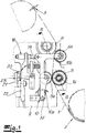
- a strapping device is shown in the figures. With the aid of the strapping device, strapping tape 1 can be guided around objects to be strapped or goods to be strapped, as is known in principle and explained in detail in the prior art already referred to in the introduction.
- the strapping 1 is for this purpose only in the Fig. 1 to be recognized tape supply 2 supplied.
- the strapping device shown only in part, also includes a closure unit 3, which is only indicated here and which is designed as a friction welding unit in the exemplary embodiment and not by way of limitation.
- the closure unit 3 ensures that the ends of the strapping band 1 to be connected to one another are coupled around the goods to be strapped after tensioning, in the present case by friction welding.
- the locking unit 3 can also open Another way to ensure the desired connection of the strap ends of the strap 1.
- the drive motor 4 is a (single) electric motor which, like a step-down or reduction gear 7 to be seen there, and a shaft bearing sleeve 8 are mounted on the rear of a flange 9.
- a gate 10 is also mounted, which will be considered in more detail below.
- the drive motor 4 the gear 7 and the shaft bearing sleeve 8 are each connected to the flange 9 parallel to one another and predominantly perpendicularly upright. This enables an optimal weight distribution to be achieved.
- the attachment of the drive motor 4 "next to" the gear 7 as well as the shaft bearing sleeve 8 ensures that the aforementioned elements 4, 7, 8 require relatively little installation space perpendicular to the flange 9.
- the motor 4 is equipped with a pulley or belt pulley 11 on its output shaft.
- a comparable belt pulley 12 is located on an input shaft of the transmission 7.
- Another belt pulley 13 can also be seen, which is arranged on the input side on a shaft 14 which is mounted within the shaft bearing sleeve 8 and carries the drive roller 5 at the other end.
- the gear 7 is additionally equipped with an integrated brake 15, which, however, is only an option and ensures or can ensure that the gear 7 and with it the tensioning roller 6 attached to its output shaft are stopped after the end of a tensioning process of the strapping band 1.
- the individual belt pulleys 11, 12, 13 are driven by the drive motor 4 via a common movement transmission means 16.
- the movement transmission means 16 is a flexible movement transmission means 16, in the present case a toothed belt.
- the individual belt pulleys 11, 12, 13 in the exemplary embodiment are also designed as toothed belt pulleys and are not restrictive.
- the drive motor 4 ensures that the gear 7 sets the tensioning roller 6 in rotation just as continuously as the drive roller 5 via the shaft bearing sleeve 8 connected in between.
- the previously mentioned pivotable link 10 is provided according to the invention.
- the gate 10 is pivotably connected to the front side of the flange 9.
- the link 10 carries at least two counter rollers 5a, 6a.
- the counter roller 6a belongs to the tensioning roller 6 and is therefore designed as a tensioning counter roller 6a.
- the further counter roller 5a is a drive counter roller 5a which belongs to the drive roller 5, as will be explained in more detail below.
- the gate 10 is overall L-shaped.
- a long L-leg 10a and a short L-leg 10b are implemented.
- the drive counter roller 5a is rotatably connected to the long L-leg 10a and is located approximately in the middle of the long L-leg 10a in question.
- the tensioning counter-roller 6a is rotatably connected to the short L-leg 10b.
- the tensioning counter-roller 6a is located at the end of the short L-leg 10b in question.
- the link 10 can be pivoted slightly to and fro about its pivot point or a pivot bearing 17 formed at this point on the front side of the flange 9, as indicated by a double arrow in FIG Fig. 1 indicates.
- the pivoting angles of the L-shaped gate 10 which are generally located below 20 degrees, and are usually only 10 degrees and less.
- the gate 10 is moved overall against the force of a spring 18, 19.
- a spring 18 belonging to the band tensioning and a further spring 19 are implemented, which primarily have an effect when the strapping band 1 is driven.
- the eccentric 20, 21, 22 is composed in detail of a cam 20 and a cam roller 21, which in turn is rotatably mounted on a cam roller lever 22.
- the cam roller lever 22 has an axis of rotation 23, with the aid of which it is rotatably mounted with respect to the flange 9.
- the strapping 1 is clamped between the tensioning roller 6 and the tensioning counter-roller 6a.
- the link 10 is acted upon in the opposite direction with the aid of the eccentric 20, 21, 22, namely executes a counterclockwise movement in relation to its pivot bearing 17.
- the drive counter roller 5a moves away from the drive roller 5
- Tensioning counter-roller 6a for resting on the tensioning roller 6.
- the strapping band 1 clamped between the two rollers 6, 6a can then be tensioned.
- the tensioned ends of the strap 1 can be connected with the aid of the closure unit 3, as was already described in the introduction.
Landscapes
- Engineering & Computer Science (AREA)
- Mechanical Engineering (AREA)
- Basic Packing Technique (AREA)
Description
- Die Erfindung betrifft eine Umreifungsvorrichtung, mit zumindest einem Antriebsmotor, ferner mit wenigstens einer Antriebsrolle für ein von einem Bandvorrat zugeführtes Umreifungsband, sowie mit zumindest einer Spannrolle zum Spannen des um das zu umreifende Gut herumgeführten Umreifungsbandes, und mit einer Verschlusseinheit zur Verbindung der Bandenden des um das Gut herumgeführten Umreifungsbandes, wobei eine schwenkbare Kulisse vorgesehen ist, welche wenigstens eine Gegenrolle an die Antriebsrolle zum Bandantrieb oder an die Spannrolle zum Bandspannen anlegt, und wobei der Antriebsmotor sowohl für den Antrieb der Antriebsrolle als auch der Spannrolle sorgt.
- Mithilfe von Umreifungsvorrichtungen wird allgemein zu umreifendes Gut wie Zeitungsstapel, Papierrollen, Pakete etc. zusammengefasst. Zu diesem Zweck wird das Umreifungsband um das betreffende und zu umreifende Gut zunächst herumgeführt. Das geschieht mithilfe der Antriebsrolle. Anschließend wird das Umreifungsband mithilfe der Spannrolle gespannt. In diesem gespannten Zustand wird eine Bandschlaufe des Umreifungsbandes von dem Bandvorrat getrennt. Außerdem werden die beiden Bandenden des Umreifungsbandes gegeneinander gepresst und miteinander in der Verschlusseinheit verbunden. Sofern es sich bei dem Umreifungsband beispielsweise um solches aus Kunststoff handelt, erfolgt die Verbindung der Bandenden durch Verschweißen, beispielsweise durch Reibschweißen.
- Im Regelfall ist die Antriebsrolle und auch die Spannrolle jeweils mit einer Gegenrolle ausgerüstet, es sind also ein Paar miteinander zusammenwirkende Antriebsrollen ebenso wie ein Paar miteinander zusammenwirkende Spannrollen realisiert, die zwischen sich jeweils das Umreifungsband einklemmen. Auf diese Weise wird mithilfe der Antriebsrolle und der Gegenrolle das Umreifungsband transportiert. Die Spannrolle sorgt in Verbindung mit der zugehörigen Gegenrolle für das Spannen des Umreifungsbandes, nachdem dieses um das zu umreifende Gut herumgeführt worden ist. Das wird im Detail im Stand der Technik nach der
DE 10 2008 004 118 B4 beschrieben. - Die bekannte Lehre nach der
DE 10 2008 004 118 B4 greift insgesamt auf lediglich einen einzigen Antriebsmotor zurück, auf dessen Motorwelle eine der Antriebsrollen angeordnet ist, das heißt die Antriebsrolle selbst oder die mit der Antriebsrolle wechselwirkende Gegenrolle bzw. die sogenannte Antriebs-Gegenrolle. Zusätzlich ist ein Bewegungsübertragungsmittel vorgesehen, welches die Bewegung der Motorwelle des Antriebsmotors zu einem Reduktionsgetriebe überträgt. Das Reduktionsgetriebe treibt mindestens eine der Spannrollen an, das heißt die Spannrolle oder auch die zugehörige Gegenrolle bzw. Spann-Gegenrolle. Das hat sich grundsätzlich bewährt, weil lediglich ein einziger Antriebsmotor für den Antrieb und auch das Spannen sorgt, wohingegen im in der Praxis realisierten Stand der Technik oftmals mit zwei Antriebsmotoren gearbeitet wird. Die Erfindung schließt jedoch beispielsweise zwei Antriebsmotoren in diesem Zusammenhang ausdrücklich nicht aus. Beispielsweise kann ein Antriebsmotor für den Antrieb der Spannrolle bzw. der Spannrollen und ein weiterer Antriebsmotor für den Antrieb der Antriebsrolle bzw. der Antriebsrollen sorgen. - Beim gattungsbildenden Stand der Technik nach der
WO 2015/117255 A1 wird eine Umreifungsvorrichtung beschrieben, die mit einem Antrieb zum Antrieb einer Bandvorschubeinrichtung, einer Bandrückzugseinrichtung und schließlich einer Spanneinrichtung dient. Auf diese Weise soll der Umreifungskopf der Umreifungsvorrichtung besonders kompakt ausgebildet werden können. Außerdem ist ein Exzenter angeordnet, der eine Gegenrolle trägt, welche einerseits an die Spannrolle und andererseits an die Antriebsrolle angestellt werden kann. - Der weitere Stand der Technik nach der
GB 2 041 869 A - Schließlich ist durch die
US 5,377,477 A eine Umreifungsvorrichtung bekannt geworden, die mit einer Kulisse arbeitet, welche zwei Gegenrollen trägt und schwenkbar ausgelegt ist. - Der Erfindung liegt das technische Problem zugrunde, eine derartige Umreifungsvorrichtung so weiterzuentwickeln, dass unter Berücksichtigung eines kompakten Aufbaus die Möglichkeit besteht, problemlos zwischen einem Antrieb des Umreifungsbandes und einem Spannvorgang schnell und funktionssicher umschalten zu können.
- Zur Lösung dieser technischen Problemstellung ist eine gattungsgemäße Umreifungsvorrichtung im Rahmen der Erfindung dadurch gekennzeichnet, dass die Kulisse zumindest zwei Gegenrollen trägt, nämlich eine Antriebs-Gegenrolle und eine Spann-Gegenrolle, dass ferner der Antriebsmotor über ein Getriebe die Spannrolle sowie unter Zwischenschaltung einer Wellenlagerhülse die Antriebsrolle beaufschlagt, und dass die Kulisse an einem Flansch drehbar gelagert ist, wobei der Antriebsmotor, das Getriebe und die Wellenlagerhülse jeweils parallel zueinander und überwiegend senkrecht aufstehend an den Flansch angeschlossen sind.
- Erfindungsgemäß wird in der Regel so vorgegangen, dass entweder der Bandantrieb oder das Bandspannen vorgenommen wird. Grundsätzlich können sich der Bandantrieb und das Bandspannen aber auch zeitlich zumindest teilweise überlappen. Meistens erfolgt jedoch zunächst der Bandantrieb. Erst wenn der Bandantrieb abgeschlossen ist, wird auf das Bandspannen gleichsam umgeschaltet.
- Im Rahmen der Erfindung wird also zunächst einmal auf die schwenkbare Kulisse zurückgegriffen. Die schwenkbare Kulisse ist in der Regel auf oder an einer Frontseite des Flansches drehbar gelagert. Demgegenüber findet sich an der Rückseite des Flansches der mindestens eine Antriebsmotor. Grundsätzlich können an dieser Stelle auch zwei Antriebsmotoren realisiert sein, nämlich ein Antriebsmotor für die Antriebsrolle und ein weiterer Antriebsmotor für die Spannrolle. Erfindungsgemäß wird hier jedoch mit einem einzigen Antriebsmotor gearbeitet, welcher sowohl die Antriebsrolle als auch die Spannrolle jeweils antreibt.
- Erfindungsgemäß sind zumindest zwei Gegenrollen vorgesehen, welche von der Kulisse getragen werden. Dazu sind die betreffenden Gegenrollen jeweils drehbar an die Kulisse angeschlossen. Das heißt, die Kulisse trägt die zumindest zwei Gegenrollen, bei denen es sich um eine Antriebs-Gegenrolle und eine Spann-Gegenrolle handelt.
- Die Antriebs-Gegenrolle sorgt bei ihrer Anlage an die Antriebsrolle dafür, dass das zwischen der Antriebsrolle und der Antriebs-Gegenrolle eingeklemmte Umreifungsband transportiert wird. Demgegenüber stellt die Spann-Gegenrolle in Verbindung mit der Spannrolle sicher, dass das dazwischen eingeklemmte Umreifungsband gespannt wird bzw. gespannt werden kann. Beide Gegenrollen, das heißt die Antriebs-Gegenrolle und die Spann-Gegenrolle sind jeweils unangetrieben und lediglich drehbar an der Kulisse gelagert. Für den zugehörigen Antrieb sorgt folglich entweder die Antriebsrolle oder die Spannrolle allein.
- Der Wechsel zwischen dem Bandantrieb und dem Bandspannen erfolgt dabei zwanglos dadurch, dass entweder die Antriebs-Gegenrolle an die Antriebsrolle angelegt wird oder alternativ hierzu die Spann-Gegenrolle an die Spannrolle. Da beim Wechsel vom Bandantrieb zum Bandspannen die jeweils nicht mehr benötigte Gegenrolle abgehoben wird, können sowohl die Antriebsrolle als auch die Spannrolle durchgängig mithilfe des einen Antriebsmotors vorteilhaft weiter betrieben und in Rotation versetzt werden. Das heißt, beim Bandantrieb wird das Umreifungsband zwischen der Antriebsrolle und der Antriebs-Gegenrolle eingeklemmt und transportiert. Da in diesem Fall die Spann-Gegenrolle von der Spannrolle abgehoben und beabstandet ist, kann das Band über die nach wie vor rotierende Spannrolle in diesem Fall problemlos gleiten.
- Umgekehrt korrespondiert das Bandspannen dazu, dass die Spann-Gegenrolle an die Spannrolle mithilfe der Kulisse angestellt wird und das Band eingeklemmt und gespannt werden kann. Da hierbei die Antriebs-Gegenrolle von der Antriebsrolle abgehoben und entfernt ist, kann die Antriebsrolle unverändert weiter rotieren und das Umreifungsband mehr oder minder widerstandsfrei über die Antriebsrolle geführt werden.
- Der Wechsel vom Bandantrieb zum Bandspannen und zurück gelingt dabei besonders einfach und funktionssicher, weil hierfür lediglich eine geringfügige Schwenkbewegung der Kulisse erforderlich ist. Tatsächlich ist die Kulisse im Allgemeinen L-förmig ausgebildet. Außerdem verfügt die Kulisse im Regelfall endseitig ihres langen L-Schenkels über eine drehbare Lagerung, die meistens gegenüber dem zuvor bereits angesprochenen Flansch beobachtet wird. Für den Wechsel vom Bandantrieb zum Bandspannen und zurück sind dabei im Allgemeinen Schwenkbewegungen der L-förmigen Kulisse ausreichend, die zu einem Schwenkwinkel unterhalb von 20 Grad und vorzugsweise sogar von 10 Grad und weniger korrespondieren. Derartige Schwenkwinkel lassen sich schnell und mechanisch einfach umsetzen.
- Tatsächlich ist die Auslegung im Detail so getroffen, dass die Kulisse nicht nur endseitig ihres langen L-Schenkels drehbar gelagert ist, sondern darüber hinaus eine der beiden Gegenrollen am langen L-Schenkel gelagert ist, während die andere Gegenrolle am kurzen L-Schenkel gelagert ist. Dabei hat sich eine Anordnung dergestalt als besonders günstig erwiesen, bei welcher die Antriebs-Gegenrolle in etwa mittig an den langen L-Schenkel der L-förmigen Kulisse angeschlossen ist. Demgegenüber findet sich die Spann-Gegenrolle im Regelfall endseitig am kurzen L-Schenkel.
- Die Kulisse wird im Allgemeinen gegen die Kraft zumindest einer Feder bewegt. Die Feder sorgt dafür, dass die Kulisse in ihrer Neutralstellung beispielsweise eine Position einnimmt, in welcher beide Gegenrollen einerseits von der Antriebsrolle und andererseits von der Spannrolle beabstandet sind. Um nun die Kulisse gegen die Kraft der zumindest einen Fehler zu bewegen und die Gegenrolle an die zugehörige angetriebene Rolle anzustellen, ist zum Verschwenken der Kulisse im Allgemeinen ein Exzenter vorgesehen. Der Exzenter ist vorteilhaft als Nocken ausgebildet bzw. weist einen solchen auf. Der Nocken kann beispielsweise über eine Kurvenrolle auf einen Kurvenrollenhebel arbeiten. Der Kurvenrollenhebel sorgt seinerseits dafür, dass die L-förmige Kulisse gegen die Kraft der ihr zugeordneten Feder verschwenkt wird.
- Wie bereits erläutert, wird erfindungsgemäß mit einem "einzigen" Antriebsmotor gearbeitet, der sowohl für den Antrieb der Antriebsrolle als auch der Spannrolle sorgt. Zu diesem Zweck beaufschlagt der Antriebsmotor erfindungsgemäß über das Getriebe die Spannrolle. Bei dem Getriebe handelt es sich vorteilhaft um ein Untersetzungsgetriebe, weil zum Spannen des Umreifungsbandes nach seinem Herumführen um das zu umreifende Gut in der Regel hohe Drehmomente benötigt werden und der Antriebsmotor im Allgemeinen als schnell laufender Elektromotor ausgebildet ist.
- Demgegenüber ist für die Beaufschlagung der Antriebsrolle im Allgemeinen keine Übersetzung des Antriebsmotors erforderlich. In diesem Fall beaufschlagt der Antriebsmotor erfindungsgemäß unter Zwischenschaltung der Wellenlagerhülse die Antriebsrolle. Die Kopplung des Antriebsmotors mit einerseits dem Getriebe und andererseits der Wellenlagerhülse erfolgt Im Allgemeinen über ein Bewegungsübertragungsmittel. Bei dem Bewegungsübertragungsmittel kann es sich um einen Riemen und insbesondere Zahnriemen handeln. Für die entsprechende Übertragung sorgen in diesem Fall Riemenscheiben bzw. Zahnriemenscheiben einerseits auf der Abtriebswelle des Antriebsmotors und andererseits auf einer Eingangswelle des Getriebes sowie einer Eingangswelle der Wellenlagerhülse.
- Auf diese Weise lassen sich die Wellenlagerhülse, das Getriebe und der Antriebsmotor in überwiegend übereinstimmender Ausrichtung praktisch parallel zueinander an der Rückseite des Flansches anbringen. Dadurch wird eine besonders kompakte Bauform zur Verfügung gestellt und lässt sich die Gewichtsverteilung gegenüber dem Flansch optimieren.
- Im Ergebnis wird eine Umreifungsvorrichtung zur Verfügung gestellt, die kompakt aufgebaut ist und funktionssicher arbeitet. Das gilt insbesondere in dem Fall, dass aus Kunststoff bestehende Umreifungsbänder verarbeitet werden sollen. Selbstverständlich kann die beschriebene Umreifungsvorrichtung auch in Verbindung mit beispielsweise Stahlbändern zum Einsatz kommen. Grundsätzlich sind natürlich auch Umreifungsbänder denkbar, die weder aus Stahl noch aus Kunststoff hergestellt sind oder bestehen, beispielsweise solche auf Basis natürlicher Rohstoffe wie beispielsweise natürlicher Polymere. Ebenso kann als Umreifungsbandmaterial auf Mischformen zurückgegriffen werden. Durch die kompakte und gedrungene Bauform lässt sich die beschriebene Umreifungsvorrichtung grundsätzlich sowohl für sogenannte Handgeräte als auch für stationäre Umreifungsmaschinen nutzen. Hierin sind die wesentlichen Vorteile zu sehen.
- Im Folgenden wird die Erfindung anhand einer lediglich ein Ausführungsbeispiel darstellenden Zeichnung näher erläutert;
- Es zeigen:
- Fig. 1
- die erfindungsgemäße Umreifungsvorrichtung schematisch in einer Frontansicht und
- Fig. 2
- einen Schnitt durch den Gegenstand nach der
Fig. 1 schematisch entlang einer Linie A-A. - In den Figuren ist eine Umreifungsvorrichtung dargestellt. Mithilfe der Umreifungsvorrichtung kann Umreifungsband 1 um zu umreifende Gegenstände bzw. zu umreifendes Gut herumgeführt werden, wie dies grundsätzlich bekannt und in dem einleitend bereits in Bezug genommenen Stand der Technik im Detail erläutert wird. Das Umreifungsband 1 wird zu diesem Zweck von einem lediglich in der
Fig. 1 zu erkennenden Bandvorrat 2 zugeführt. Zu der in derFig. 1 lediglich ausschnittsweise dargestellten Umreifungsvorrichtung gehört noch eine hier lediglich angedeutete Verschlusseinheit 3, die im Ausführungsbeispiel und nicht einschränkend als Reibschweißeinheit ausgebildet ist. Die Verschlusseinheit 3 sorgt dafür, dass miteinander zu verbindende Bandenden des Umreifungsbandes 1 nach dem Spannen um das zu umreifende Gut gekoppelt werden, vorliegend durch Reibschweißen. Selbstverständlich kann die Verschlusseinheit 3 auch auf anderem Wege für die gewünschte Verbindung der Bandenden des Umreifungsbandes 1 sorgen. - Entscheidend für die vorliegende Erfindung sind nun ein in der
Fig. 2 zu erkennender Antriebsmotor 4, mit dessen Hilfe im Ausführungsbeispiel und nicht einschränkend sowohl eine Antriebsrolle 5 als auch eine Spannrolle 6 angetrieben werden. Ausweislich derFig. 2 handelt es sich bei dem Antriebsmotor 4 um einen (einzigen) Elektromotor, welcher ebenso wie ein dort zu erkennendes Untersetzungs- bzw. Reduktionsgetriebe 7 und eine Wellenlagerhülse 8 insgesamt an der Rückseite eines Flansches 9 gelagert sind. An dem Flansch 9 ist an seiner Vorderseite darüber hinaus noch eine Kulisse 10 gelagert, die nachfolgend noch näher betrachtet wird. - Anhand der Schnittdarstellung in der
Fig. 2 erkennt man, dass der Antriebsmotor 4, das Getriebe 7 und die Wellenlagerhülse 8 jeweils parallel zueinander und überwiegend senkrecht aufstehend an den Flansch 9 angeschlossen sind. Dadurch lässt sich eine optimale Gewichtsverteilung erreichen. Außerdem sorgt die Anbringung des Antriebsmotors 4 "neben" dem Getriebe 7 ebenso wie der Wellenlagerhülse 8 dafür, dass die vorgenannten Elemente 4, 7, 8 senkrecht vom Flansch 9 entfernt relativ wenig Bauraum benötigen. Der Motor 4 ist auf seiner Abtriebswelle mit einer Scheibe bzw. Riemenscheibe 11 ausgerüstet. Eine vergleichbare Riemenscheibe 12 findet sich auf einer Eingangswelle des Getriebes 7. Ebenso erkennt man eine weitere Riemenscheibe 13, welche eingangsseitig auf einer Welle 14 angeordnet ist, die innerhalb der Wellenlagerhülse 8 gelagert ist und am anderen Ende die Antriebsrolle 5 trägt. Das Getriebe 7 ist zusätzlich noch mit einer integrierten Bremse 15 ausgerüstet, die jedoch lediglich eine Option darstellt und dafür sorgt oder sorgen kann, dass nach Beendigung eines Spannvorganges des Umreifungsbandes 1 das Getriebe 7 und mit ihm die auf seiner Ausgangswelle befestigte Spannrolle 6 angehalten wird. - Die einzelnen Riemenscheiben 11, 12, 13 werden im Ausführungsbeispiel über ein gemeinsames Bewegungsübertragungsmittel 16 von dem Antriebsmotor 4 angetrieben. Bei dem Bewegungsübertragungsmittel 16 handelt es sich um ein flexibles Bewegungsübertragungsmittel 16, vorliegend einen Zahnriemen. Dementsprechend sind auch die einzelnen Riemenscheiben 11, 12, 13 im Ausführungsbeispiel und nicht einschränkend als Zahnriemenscheiben ausgebildet. Der Antriebsmotor 4 sorgt insgesamt dafür, dass das Getriebe 7 die Spannrolle 6 ebenso durchgängig in Rotationen versetzt wie die Antriebsrolle 5 über die zwischengeschaltete Wellenlagerhülse 8.
- Um nun zwischen einem einleitend bereits beschriebenen Bandantrieb des Umreifungsbandes 1 und einem Bandspannen unterscheiden zu können, ist erfindungsgemäß die zuvor bereits angesprochene schwenkbare Kulisse 10 vorgesehen. Die Kulisse 10 ist schwenkbar an die Frontseite des Flansches 9 angeschlossen. Zu diesem Zweck trägt die Kulisse 10 zumindest zwei Gegenrollen 5a, 6a. Die Gegenrolle 6a gehört zur Spannrolle 6 und ist demzufolge als Spann-Gegenrolle 6a ausgebildet. Bei der weiteren Gegenrolle 5a handelt es sich demgegenüber um eine Antriebs-Gegenrolle 5a, die zu der Antriebsrolle 5 gehört, wie nachfolgend noch näher erläutert wird.
- Anhand der in der
Fig. 1 dargestellten Frontansicht erkennt man, dass die Kulisse 10 insgesamt L-förmig ausgebildet ist. Tatsächlich ist ein langer L-Schenkel 10a und ein kurzer L-Schenkel 10b realisiert. Die Antriebs-Gegenrolle 5a ist nach dem Ausführungsbeispiel an den langen L-Schenkel 10a drehbar angeschlossen, befindet sich in etwa mittig des fraglichen langen L-Schenkels 10a. Demgegenüber ist die Spann-Gegenrolle 6a an den kurzen L-Schenkel 10b drehbar angeschlossen. Tatsächlich befindet sich die Spann-Gegenrolle 6a endseitig des fraglichen und kurzen L-Schenkels 10b. - Die Kulisse 10 kann um ihren Drehpunkt bzw. ein an dieser Stelle an der Frontseite des Flansches 9 ausgebildetes Drehlager 17 geringfügig hin- und hergeschwenkt werden, wie dies ein Doppelpfeil in der
Fig. 1 andeutet. Hierzu korrespondieren Schwenkwinkel der L-förmigen Kulisse 10, die im Regelfall unterhalb von 20 Grad angesiedelt sind, meistens sogar nur 10 Grad und weniger betragen. Die Kulisse 10 wird dabei insgesamt gegen die Kraft einer Feder 18, 19 bewegt. Tatsächlich sind im Rahmen des Ausführungsbeispiels eine zum Bandspannen gehörige Feder 18 und eine weitere Feder 19 realisiert, die beim Antrieb des Umreifungsbandes 1 primär Wirkung entfaltet. - Zum Verschwenken der L-förmigen Kulisse 10 ist insgesamt ein Exzenter 20, 21, 22 vorgesehen. Der Exzenter 20, 21, 22 setzt sich im Detail aus einem Nocken 20 und einer Kurvenrolle 21 zusammen, die ihrerseits drehbar auf einem Kurvenrollenhebel 22 gelagert ist. Der Kurvenrollenhebel 22 verfügt über eine Drehachse 23, mit deren Hilfe er drehbar gegenüber dem Flansch 9 gelagert ist.
- Drehbewegungen des Nockens 20 um eine in der
Fig. 1 angedeutete und in der Zeichenebene bzw. parallel hierzu verlaufende Achse führen nun dazu, dass über die Kurvenrolle 21 der Kurvenrollenhebel 22 im Vergleich zu seinem Drehlager 23 eine in derFig. 1 ebenfalls angedeutete Schwenkbewegung vollführt. Als Folge hiervon wird auch die L-förmige Kulisse 10 verschwenkt, weil der Kurvenrollenhebel 22 an das der Spann-Gegenrolle 6a gegenüberliegende Ende des kurzen L-Schenkels 10b der L-förmigen Kulisse 10 angeschlossen ist und auf diese Weise die Kulisse 10 bei seiner Schwenkbewegung "mitnimmt". - Wird beispielsweise ein Bandantrieb des Umreifungsbandes 1 gefordert, so korrespondiert dies dazu, dass die L-förmige Kulisse 10 um ihr Drehlager 17 im Uhrzeigersinn verschwenkt wird. Dadurch kommt die Antriebs-Gegenrolle 5a zur Anlage an der Antriebsrolle 5 und das Umreifungsband 1 wird zwischen den beiden Rollen 5, 5a festgeklemmt. Als Folge hiervon wird das Umreifungsband 1 ausgehend vom Bandvorrat 2 abgewickelt und kann beispielsweise mithilfe eines Bandführungskanals um das zu umreifende Gut herumgeführt werden. Sobald das Umreifungsband 1 um das Gut herumgeführt worden ist, wird das Umreifungsband 1 gegenüber dem Bandvorrat 2 bzw. die Bandschlaufe mithilfe einer nicht dargestellten Trenneinheit abgetrennt. Die beiden Enden des Umreifungsbandes 1 werden festgehalten. Jetzt wird das Umreifungsband 1 gespannt.
- Dazu wird das Umreifungsband 1 zwischen der Spannrolle 6 und der Spann-Gegenrolle 6a eingeklemmt. Um dies zu erreichen, wird die Kulisse 10 in Gegenrichtung mithilfe des Exzenters 20, 21, 22 beaufschlagt, vollführt nämlich eine Gegenuhrzeigersinnbewegung in Bezug auf ihr Drehlager 17. Als Folge hiervon entfernt sich die Antriebs-Gegenrolle 5a von der Antriebsrolle 5, kommt vielmehr die Spann-Gegenrolle 6a zur Anlage an der Spannrolle 6. Das zwischen den beiden Rollen 6, 6a eingeklemmte Umreifungsband 1 kann nachfolgend gespannt werden. Außerdem lassen sich die gespannten Enden des Umreifungsbandes 1 mithilfe der Verschlusseinheit 3 verbinden, wie dies einleitend bereits beschrieben wurde.
Claims (10)
- Umreifungsvorrichtung, mit zumindest einem Antriebsmotor (4), ferner mit wenigstens einer Antriebsrolle (5) für ein von einem Bandvorrat (2) zugeführtes Umreifungsband (1), sowie mit zumindest einer Spannrolle (6) zum Spannen des um zu umreifendes Gut herumgeführten Umreifungsbandes (1), und mit einer Verschlusseinheit (3) zur Verbindung der Bandenden des um das Gut herumgeführten Umreifungsbandes (1), wobei
eine schwenkbare Kulisse (10) vorgesehen ist, welche wenigstens eine Gegenrolle (5a, 6a) an die Antriebsrolle (5) zum Bandantrieb oder an die Spannrolle (6) zum Bandspannen anlegt, und wobei
der Antriebsmotor (4) sowohl für den Antrieb der Antriebsrolle (5) als auch der Spannrolle (6) sorgt,
dadurch gekennzeichnet, dass- die Kulisse (10) zumindest zwei Gegenrollen (5a, 6a) trägt, nämlich eine Antriebs-Gegenrolle (5a) und eine Spann-Gegenrolle (6a), dass ferner- der Antriebsmotor (4) über ein Getriebe (7) die Spannrolle (6) sowie unter Zwischenschaltung einer Wellenlagerhülse (8) die Antriebsrolle (5) beaufschlagt, und dass- die Kulisse (10) an einem Flansch (9) drehbar gelagert ist, wobei- der Antriebsmotor (4), das Getriebe (7) und die Wellenlagerhülse (8) jeweils parallel zueinander und überwiegend senkrecht aufstehend an dem Flansch (9) angeschlossen sind. - Umreifungsvorrichtung nach Anspruch 1, dadurch gekennzeichnet, dass der Flansch (9) auf seiner Frontseite die Kulisse (10) und auf seiner Rückseite den Antriebsmotor (4) sowie das Getriebe (7) und die Wellenlagerhülse (8) aufnimmt.
- Umreifunungsvorrichtung nach Anspruch 1 oder 2, dadurch gekennzeichnet, dass die Kulisse (10) L-förmig ausgebildet ist.
- Umreifungsvorrichtung nach Anspruch 3, dadurch gekennzeichnet, dass die Kulisse (10) endseitig ihres langen L-Schenkels (10a) drehbar gelagert ist.
- Umreifungsvorrichtung nach Anspruch 3 oder 4, dadurch gekennzeichnet, dass die eine Gegenrolle (5a) am langen L-Schenkel (10a) und die andere Gegenrolle (6a) am kurzen L-Schenkel (10b) gelagert ist,
- Umreifungsvorrichtung nach Anspruch 5, dadurch gekennzeichnet, dass die Antriebs-Gegenrolle (5a) in etwa mittig an den langen L-Schenkel (10a) angeschlossen ist.
- Umreifungsvorrichtung nach einem der Ansprüche 4 bis 6, dadurch gekennzeichnet, dass die Spann-Gegenrolle (6a) an den kurzen L-Schenkel (10b) angeschlossen ist.
- Umreifungsvorrichtung nach einem der Ansprüche 1 bis 7, dadurch gekennzeichnet, dass die Kulisse (10) gegen die Kraft zumindest einer Feder (18, 19) bewegt wird.
- Umreifungsvorrichtung nach einem der Ansprüche 1 bis 8, dadurch gekennzeichnet, dass zum Verschwenken der Kulisse (10) ein Exzenter (20, 21, 22) vorgesehen ist.
- Umreifungsvorrichtung nach Anspruch 9, dadurch gekennzeichnet, dass der Exzenter (20, 21, 22) einen Nocken (20) aufweist, welcher beispielsweise über eine Kurvenrolle (21) und einen Kurvenrollenhebel (22) auf die Kulisse (10) arbeitet.
Priority Applications (4)
| Application Number | Priority Date | Filing Date | Title |
|---|---|---|---|
| EP18168243.6A EP3556667B1 (de) | 2018-04-19 | 2018-04-19 | Umreifungsvorrichtung |
| ES18168243T ES2870996T3 (es) | 2018-04-19 | 2018-04-19 | Dispositivo de zunchado |
| US16/387,616 US11027866B2 (en) | 2018-04-19 | 2019-04-18 | Strapping apparatus |
| CN201910315309.2A CN110386285B (zh) | 2018-04-19 | 2019-04-19 | 捆扎装置 |
Applications Claiming Priority (1)
| Application Number | Priority Date | Filing Date | Title |
|---|---|---|---|
| EP18168243.6A EP3556667B1 (de) | 2018-04-19 | 2018-04-19 | Umreifungsvorrichtung |
Publications (3)
| Publication Number | Publication Date |
|---|---|
| EP3556667A1 EP3556667A1 (de) | 2019-10-23 |
| EP3556667A8 EP3556667A8 (de) | 2020-01-08 |
| EP3556667B1 true EP3556667B1 (de) | 2021-04-14 |
Family
ID=62027874
Family Applications (1)
| Application Number | Title | Priority Date | Filing Date |
|---|---|---|---|
| EP18168243.6A Active EP3556667B1 (de) | 2018-04-19 | 2018-04-19 | Umreifungsvorrichtung |
Country Status (4)
| Country | Link |
|---|---|
| US (1) | US11027866B2 (de) |
| EP (1) | EP3556667B1 (de) |
| CN (1) | CN110386285B (de) |
| ES (1) | ES2870996T3 (de) |
Families Citing this family (2)
| Publication number | Priority date | Publication date | Assignee | Title |
|---|---|---|---|---|
| CN113978791B (zh) * | 2021-11-05 | 2023-01-10 | 北京航星机器制造有限公司 | 一种扎带机 |
| EP4613657A1 (de) * | 2024-03-04 | 2025-09-10 | TITAN Umreifungstechnik GmbH & Co.KG | Umreifungsvorrichtung mit spannkraftmessung |
Family Cites Families (14)
| Publication number | Priority date | Publication date | Assignee | Title |
|---|---|---|---|---|
| GB885371A (en) * | 1959-04-18 | 1961-12-28 | Ver Metaalverpakking Mij Nv | Machine for securing a metal strap around a container, box, package or the like |
| US3232217A (en) * | 1964-05-04 | 1966-02-01 | Stanley Works | Strapping machine |
| US3536430A (en) * | 1967-11-21 | 1970-10-27 | Ikegai Iron Works Ltd | Automatic strapping machine |
| US4218969A (en) * | 1979-02-01 | 1980-08-26 | Nichiro Kogyo Company, Limited | Band feeding and tightening apparatus for strapping machine |
| GB2041869B (en) | 1979-02-23 | 1982-12-08 | Nichiro Kogyo Kk | Band feeding and tightening method and device for strapping machinqe |
| DE4014307C2 (de) * | 1990-05-04 | 1996-11-07 | Rmo Systempack Gmbh | Packmaschine |
| US5112004A (en) * | 1990-11-07 | 1992-05-12 | Illinois Tool Works Inc. | Strap dispensing and accumulating apparatus and combination of same with strapping machine |
| US5377477A (en) * | 1993-12-09 | 1995-01-03 | Signode Corporation | Method and apparatus for a power strapping machine |
| US5459977A (en) * | 1993-12-09 | 1995-10-24 | Illinois Tool Works Inc. | Method and apparatus for an improved power strapping machine |
| US6155032A (en) * | 1999-09-09 | 2000-12-05 | Lai; Chien-Fa | Automatic wrapper |
| DE102008004118B4 (de) | 2008-01-11 | 2011-04-14 | Maschinenfabrik Gerd Mosca Ag | Umreifungsmaschine mit einem Bandführungskanal und einer Zufuhreinheit |
| PL3105127T3 (pl) * | 2014-02-10 | 2019-11-29 | Orgapack Gmbh | Urządzenie do spinania taśmą |
| DE102014105126A1 (de) * | 2014-04-10 | 2015-10-15 | Krones Aktiengesellschaft | Bandantriebseinrichtung einer Umreifungsmaschine |
| CN107842764A (zh) * | 2017-11-17 | 2018-03-27 | 盱眙县生产力促进中心 | 一种物理学科用方便除尘的led灯 |
-
2018
- 2018-04-19 ES ES18168243T patent/ES2870996T3/es active Active
- 2018-04-19 EP EP18168243.6A patent/EP3556667B1/de active Active
-
2019
- 2019-04-18 US US16/387,616 patent/US11027866B2/en active Active
- 2019-04-19 CN CN201910315309.2A patent/CN110386285B/zh not_active Expired - Fee Related
Also Published As
| Publication number | Publication date |
|---|---|
| EP3556667A1 (de) | 2019-10-23 |
| ES2870996T3 (es) | 2021-10-28 |
| US20190322398A1 (en) | 2019-10-24 |
| EP3556667A8 (de) | 2020-01-08 |
| CN110386285A (zh) | 2019-10-29 |
| US11027866B2 (en) | 2021-06-08 |
| CN110386285B (zh) | 2022-07-26 |
Similar Documents
| Publication | Publication Date | Title |
|---|---|---|
| EP0711724B1 (de) | Trenneinrichtung zum Abtrennen perforierter Schlauchabschnitte | |
| EP3105126B1 (de) | Spanneinrichtung für eine umreifungsvorrichtung | |
| CH712984A2 (de) | Umreifungsvorrichtung zur Umreifung von Packgut mit einem Umreifungsband. | |
| EP1074500B1 (de) | Exemplarführender Zylinder eines Falzapparates | |
| EP3556667B1 (de) | Umreifungsvorrichtung | |
| DE4344622A1 (de) | Räderfalzapparat für eine Rotationsdruckmaschine | |
| CH629724A5 (de) | Falzmaschine mit einem schwertfalzwerk. | |
| DE1436785A1 (de) | Maschine zum fortlaufenden Herstellen von Flachbeuteln | |
| EP3336019B1 (de) | Justiereinrichtung | |
| EP0232553B1 (de) | Einrichtung zum Aufwickeln eines kontinuierlich anfallenden Schuppenstromes von biegsamen Flächengebilden zu einem Wickel | |
| DE102020107945B4 (de) | Umreifungsvorrichtung mit Einrichtung zum Drehen eines Packstückes | |
| CH660578A5 (de) | Verfahren und einrichtung zur durchlaufhandhabung von blattfoermigen gegenstaenden. | |
| EP0847922B1 (de) | Vorrichtung zum Umreifen von Packstücken | |
| CH709244A2 (de) | Spanneinrichtung einer Umreifungsvorrichtung zur Umreifung von Packgut mit einem Umreifungsband. | |
| CH709245A2 (de) | Umreifungseinrichtung einer Umreifungsvorrichtung zur Umreifung von Packgut mit einem Umreifungsband. | |
| CH709246A2 (de) | Umreifungseinrichtung einer Umreifungsvorrichtung zur Umreifung von Packgut mit einem Umreifungsband. | |
| EP2930116B1 (de) | Bandantriebseinrichtung einer umreifungsmaschine | |
| DE3335645C2 (de) | ||
| EP3328629B1 (de) | Vorrichtung und verfahren zum fixieren eines offenen bodens eines schlauchstücks | |
| CH686774A5 (de) | Bandklemmeinrichtung. | |
| EP0695687A2 (de) | Vorrichtung zum Umreifen von Packgut | |
| DE1436785C (de) | Maschine zum fortlaufenden Herstellen von Flachbeuteln | |
| EP0415272A1 (de) | Anordnung an einem Umreifungsgerät zum Spannen einer um einen zu umreifenden Gegenstand gelegten Schlaufe | |
| DE1660975B1 (de) | Naehwegkopiervorrichtung | |
| DE19936842A1 (de) | Exemplarführender Zylinder eines Falzapparates |
Legal Events
| Date | Code | Title | Description |
|---|---|---|---|
| PUAI | Public reference made under article 153(3) epc to a published international application that has entered the european phase |
Free format text: ORIGINAL CODE: 0009012 |
|
| STAA | Information on the status of an ep patent application or granted ep patent |
Free format text: STATUS: THE APPLICATION HAS BEEN PUBLISHED |
|
| AK | Designated contracting states |
Kind code of ref document: A1 Designated state(s): AL AT BE BG CH CY CZ DE DK EE ES FI FR GB GR HR HU IE IS IT LI LT LU LV MC MK MT NL NO PL PT RO RS SE SI SK SM TR |
|
| AX | Request for extension of the european patent |
Extension state: BA ME |
|
| RIN1 | Information on inventor provided before grant (corrected) |
Inventor name: ANDREAS, BJOERN Inventor name: NEUMANN, FRANK |
|
| STAA | Information on the status of an ep patent application or granted ep patent |
Free format text: STATUS: REQUEST FOR EXAMINATION WAS MADE |
|
| 17P | Request for examination filed |
Effective date: 20200304 |
|
| RBV | Designated contracting states (corrected) |
Designated state(s): AL AT BE BG CH CY CZ DE DK EE ES FI FR GB GR HR HU IE IS IT LI LT LU LV MC MK MT NL NO PL PT RO RS SE SI SK SM TR |
|
| GRAP | Despatch of communication of intention to grant a patent |
Free format text: ORIGINAL CODE: EPIDOSNIGR1 |
|
| STAA | Information on the status of an ep patent application or granted ep patent |
Free format text: STATUS: GRANT OF PATENT IS INTENDED |
|
| GRAS | Grant fee paid |
Free format text: ORIGINAL CODE: EPIDOSNIGR3 |
|
| INTG | Intention to grant announced |
Effective date: 20210119 |
|
| GRAA | (expected) grant |
Free format text: ORIGINAL CODE: 0009210 |
|
| STAA | Information on the status of an ep patent application or granted ep patent |
Free format text: STATUS: THE PATENT HAS BEEN GRANTED |
|
| AK | Designated contracting states |
Kind code of ref document: B1 Designated state(s): AL AT BE BG CH CY CZ DE DK EE ES FI FR GB GR HR HU IE IS IT LI LT LU LV MC MK MT NL NO PL PT RO RS SE SI SK SM TR |
|
| REG | Reference to a national code |
Ref country code: GB Ref legal event code: FG4D Free format text: NOT ENGLISH |
|
| REG | Reference to a national code |
Ref country code: CH Ref legal event code: EP |
|
| REG | Reference to a national code |
Ref country code: DE Ref legal event code: R096 Ref document number: 502018004754 Country of ref document: DE |
|
| REG | Reference to a national code |
Ref country code: IE Ref legal event code: FG4D Free format text: LANGUAGE OF EP DOCUMENT: GERMAN |
|
| REG | Reference to a national code |
Ref country code: AT Ref legal event code: REF Ref document number: 1382171 Country of ref document: AT Kind code of ref document: T Effective date: 20210515 |
|
| REG | Reference to a national code |
Ref country code: LT Ref legal event code: MG9D |
|
| REG | Reference to a national code |
Ref country code: NL Ref legal event code: MP Effective date: 20210414 |
|
| REG | Reference to a national code |
Ref country code: ES Ref legal event code: FG2A Ref document number: 2870996 Country of ref document: ES Kind code of ref document: T3 Effective date: 20211028 |
|
| PG25 | Lapsed in a contracting state [announced via postgrant information from national office to epo] |
Ref country code: NL Free format text: LAPSE BECAUSE OF FAILURE TO SUBMIT A TRANSLATION OF THE DESCRIPTION OR TO PAY THE FEE WITHIN THE PRESCRIBED TIME-LIMIT Effective date: 20210414 Ref country code: BG Free format text: LAPSE BECAUSE OF FAILURE TO SUBMIT A TRANSLATION OF THE DESCRIPTION OR TO PAY THE FEE WITHIN THE PRESCRIBED TIME-LIMIT Effective date: 20210714 Ref country code: HR Free format text: LAPSE BECAUSE OF FAILURE TO SUBMIT A TRANSLATION OF THE DESCRIPTION OR TO PAY THE FEE WITHIN THE PRESCRIBED TIME-LIMIT Effective date: 20210414 Ref country code: LT Free format text: LAPSE BECAUSE OF FAILURE TO SUBMIT A TRANSLATION OF THE DESCRIPTION OR TO PAY THE FEE WITHIN THE PRESCRIBED TIME-LIMIT Effective date: 20210414 Ref country code: FI Free format text: LAPSE BECAUSE OF FAILURE TO SUBMIT A TRANSLATION OF THE DESCRIPTION OR TO PAY THE FEE WITHIN THE PRESCRIBED TIME-LIMIT Effective date: 20210414 |
|
| PG25 | Lapsed in a contracting state [announced via postgrant information from national office to epo] |
Ref country code: GR Free format text: LAPSE BECAUSE OF FAILURE TO SUBMIT A TRANSLATION OF THE DESCRIPTION OR TO PAY THE FEE WITHIN THE PRESCRIBED TIME-LIMIT Effective date: 20210715 Ref country code: IS Free format text: LAPSE BECAUSE OF FAILURE TO SUBMIT A TRANSLATION OF THE DESCRIPTION OR TO PAY THE FEE WITHIN THE PRESCRIBED TIME-LIMIT Effective date: 20210814 Ref country code: LV Free format text: LAPSE BECAUSE OF FAILURE TO SUBMIT A TRANSLATION OF THE DESCRIPTION OR TO PAY THE FEE WITHIN THE PRESCRIBED TIME-LIMIT Effective date: 20210414 Ref country code: PT Free format text: LAPSE BECAUSE OF FAILURE TO SUBMIT A TRANSLATION OF THE DESCRIPTION OR TO PAY THE FEE WITHIN THE PRESCRIBED TIME-LIMIT Effective date: 20210816 Ref country code: NO Free format text: LAPSE BECAUSE OF FAILURE TO SUBMIT A TRANSLATION OF THE DESCRIPTION OR TO PAY THE FEE WITHIN THE PRESCRIBED TIME-LIMIT Effective date: 20210714 Ref country code: PL Free format text: LAPSE BECAUSE OF FAILURE TO SUBMIT A TRANSLATION OF THE DESCRIPTION OR TO PAY THE FEE WITHIN THE PRESCRIBED TIME-LIMIT Effective date: 20210414 Ref country code: RS Free format text: LAPSE BECAUSE OF FAILURE TO SUBMIT A TRANSLATION OF THE DESCRIPTION OR TO PAY THE FEE WITHIN THE PRESCRIBED TIME-LIMIT Effective date: 20210414 Ref country code: SE Free format text: LAPSE BECAUSE OF FAILURE TO SUBMIT A TRANSLATION OF THE DESCRIPTION OR TO PAY THE FEE WITHIN THE PRESCRIBED TIME-LIMIT Effective date: 20210414 |
|
| PG25 | Lapsed in a contracting state [announced via postgrant information from national office to epo] |
Ref country code: LU Free format text: LAPSE BECAUSE OF NON-PAYMENT OF DUE FEES Effective date: 20210419 |
|
| REG | Reference to a national code |
Ref country code: DE Ref legal event code: R097 Ref document number: 502018004754 Country of ref document: DE |
|
| REG | Reference to a national code |
Ref country code: BE Ref legal event code: MM Effective date: 20210430 |
|
| PG25 | Lapsed in a contracting state [announced via postgrant information from national office to epo] |
Ref country code: SM Free format text: LAPSE BECAUSE OF FAILURE TO SUBMIT A TRANSLATION OF THE DESCRIPTION OR TO PAY THE FEE WITHIN THE PRESCRIBED TIME-LIMIT Effective date: 20210414 Ref country code: SK Free format text: LAPSE BECAUSE OF FAILURE TO SUBMIT A TRANSLATION OF THE DESCRIPTION OR TO PAY THE FEE WITHIN THE PRESCRIBED TIME-LIMIT Effective date: 20210414 Ref country code: EE Free format text: LAPSE BECAUSE OF FAILURE TO SUBMIT A TRANSLATION OF THE DESCRIPTION OR TO PAY THE FEE WITHIN THE PRESCRIBED TIME-LIMIT Effective date: 20210414 Ref country code: RO Free format text: LAPSE BECAUSE OF FAILURE TO SUBMIT A TRANSLATION OF THE DESCRIPTION OR TO PAY THE FEE WITHIN THE PRESCRIBED TIME-LIMIT Effective date: 20210414 Ref country code: CH Free format text: LAPSE BECAUSE OF NON-PAYMENT OF DUE FEES Effective date: 20210430 Ref country code: CZ Free format text: LAPSE BECAUSE OF FAILURE TO SUBMIT A TRANSLATION OF THE DESCRIPTION OR TO PAY THE FEE WITHIN THE PRESCRIBED TIME-LIMIT Effective date: 20210414 Ref country code: DK Free format text: LAPSE BECAUSE OF FAILURE TO SUBMIT A TRANSLATION OF THE DESCRIPTION OR TO PAY THE FEE WITHIN THE PRESCRIBED TIME-LIMIT Effective date: 20210414 Ref country code: LI Free format text: LAPSE BECAUSE OF NON-PAYMENT OF DUE FEES Effective date: 20210430 Ref country code: MC Free format text: LAPSE BECAUSE OF FAILURE TO SUBMIT A TRANSLATION OF THE DESCRIPTION OR TO PAY THE FEE WITHIN THE PRESCRIBED TIME-LIMIT Effective date: 20210414 |
|
| PLBE | No opposition filed within time limit |
Free format text: ORIGINAL CODE: 0009261 |
|
| STAA | Information on the status of an ep patent application or granted ep patent |
Free format text: STATUS: NO OPPOSITION FILED WITHIN TIME LIMIT |
|
| 26N | No opposition filed |
Effective date: 20220117 |
|
| PG25 | Lapsed in a contracting state [announced via postgrant information from national office to epo] |
Ref country code: IE Free format text: LAPSE BECAUSE OF NON-PAYMENT OF DUE FEES Effective date: 20210419 |
|
| PG25 | Lapsed in a contracting state [announced via postgrant information from national office to epo] |
Ref country code: IS Free format text: LAPSE BECAUSE OF FAILURE TO SUBMIT A TRANSLATION OF THE DESCRIPTION OR TO PAY THE FEE WITHIN THE PRESCRIBED TIME-LIMIT Effective date: 20210814 Ref country code: FR Free format text: LAPSE BECAUSE OF NON-PAYMENT OF DUE FEES Effective date: 20210614 Ref country code: AL Free format text: LAPSE BECAUSE OF FAILURE TO SUBMIT A TRANSLATION OF THE DESCRIPTION OR TO PAY THE FEE WITHIN THE PRESCRIBED TIME-LIMIT Effective date: 20210414 |
|
| PG25 | Lapsed in a contracting state [announced via postgrant information from national office to epo] |
Ref country code: BE Free format text: LAPSE BECAUSE OF NON-PAYMENT OF DUE FEES Effective date: 20210430 |
|
| GBPC | Gb: european patent ceased through non-payment of renewal fee |
Effective date: 20220419 |
|
| PG25 | Lapsed in a contracting state [announced via postgrant information from national office to epo] |
Ref country code: GB Free format text: LAPSE BECAUSE OF NON-PAYMENT OF DUE FEES Effective date: 20220419 |
|
| PG25 | Lapsed in a contracting state [announced via postgrant information from national office to epo] |
Ref country code: CY Free format text: LAPSE BECAUSE OF FAILURE TO SUBMIT A TRANSLATION OF THE DESCRIPTION OR TO PAY THE FEE WITHIN THE PRESCRIBED TIME-LIMIT Effective date: 20210414 |
|
| PG25 | Lapsed in a contracting state [announced via postgrant information from national office to epo] |
Ref country code: HU Free format text: LAPSE BECAUSE OF FAILURE TO SUBMIT A TRANSLATION OF THE DESCRIPTION OR TO PAY THE FEE WITHIN THE PRESCRIBED TIME-LIMIT; INVALID AB INITIO Effective date: 20180419 |
|
| PG25 | Lapsed in a contracting state [announced via postgrant information from national office to epo] |
Ref country code: MK Free format text: LAPSE BECAUSE OF FAILURE TO SUBMIT A TRANSLATION OF THE DESCRIPTION OR TO PAY THE FEE WITHIN THE PRESCRIBED TIME-LIMIT Effective date: 20210414 |
|
| PG25 | Lapsed in a contracting state [announced via postgrant information from national office to epo] |
Ref country code: TR Free format text: LAPSE BECAUSE OF FAILURE TO SUBMIT A TRANSLATION OF THE DESCRIPTION OR TO PAY THE FEE WITHIN THE PRESCRIBED TIME-LIMIT Effective date: 20210414 |
|
| PG25 | Lapsed in a contracting state [announced via postgrant information from national office to epo] |
Ref country code: MT Free format text: LAPSE BECAUSE OF FAILURE TO SUBMIT A TRANSLATION OF THE DESCRIPTION OR TO PAY THE FEE WITHIN THE PRESCRIBED TIME-LIMIT Effective date: 20210414 |
|
| PGFP | Annual fee paid to national office [announced via postgrant information from national office to epo] |
Ref country code: DE Payment date: 20250414 Year of fee payment: 8 |
|
| PGFP | Annual fee paid to national office [announced via postgrant information from national office to epo] |
Ref country code: ES Payment date: 20250530 Year of fee payment: 8 |
|
| PGFP | Annual fee paid to national office [announced via postgrant information from national office to epo] |
Ref country code: IT Payment date: 20250424 Year of fee payment: 8 |
|
| PGFP | Annual fee paid to national office [announced via postgrant information from national office to epo] |
Ref country code: AT Payment date: 20250423 Year of fee payment: 8 |