EP3556667B1 - Dispositif de cerclage - Google Patents
Dispositif de cerclage Download PDFInfo
- Publication number
- EP3556667B1 EP3556667B1 EP18168243.6A EP18168243A EP3556667B1 EP 3556667 B1 EP3556667 B1 EP 3556667B1 EP 18168243 A EP18168243 A EP 18168243A EP 3556667 B1 EP3556667 B1 EP 3556667B1
- Authority
- EP
- European Patent Office
- Prior art keywords
- roller
- drive
- tensioning
- counter
- link
- Prior art date
- Legal status (The legal status is an assumption and is not a legal conclusion. Google has not performed a legal analysis and makes no representation as to the accuracy of the status listed.)
- Active
Links
- 230000005540 biological transmission Effects 0.000 description 10
- 239000000463 material Substances 0.000 description 4
- 230000009467 reduction Effects 0.000 description 4
- 238000003466 welding Methods 0.000 description 4
- 230000008859 change Effects 0.000 description 3
- 238000000034 method Methods 0.000 description 3
- 229910000831 Steel Inorganic materials 0.000 description 2
- 230000008569 process Effects 0.000 description 2
- 239000010959 steel Substances 0.000 description 2
- 230000000694 effects Effects 0.000 description 1
- 230000002349 favourable effect Effects 0.000 description 1
- 238000009434 installation Methods 0.000 description 1
- 230000003993 interaction Effects 0.000 description 1
- 229920005615 natural polymer Polymers 0.000 description 1
- 230000007935 neutral effect Effects 0.000 description 1
- 239000002994 raw material Substances 0.000 description 1
- 230000000284 resting effect Effects 0.000 description 1
Images

Classifications
-
- B—PERFORMING OPERATIONS; TRANSPORTING
- B65—CONVEYING; PACKING; STORING; HANDLING THIN OR FILAMENTARY MATERIAL
- B65B—MACHINES, APPARATUS OR DEVICES FOR, OR METHODS OF, PACKAGING ARTICLES OR MATERIALS; UNPACKING
- B65B13/00—Bundling articles
- B65B13/18—Details of, or auxiliary devices used in, bundling machines or bundling tools
- B65B13/185—Details of tools
- B65B13/187—Motor means
-
- B—PERFORMING OPERATIONS; TRANSPORTING
- B65—CONVEYING; PACKING; STORING; HANDLING THIN OR FILAMENTARY MATERIAL
- B65B—MACHINES, APPARATUS OR DEVICES FOR, OR METHODS OF, PACKAGING ARTICLES OR MATERIALS; UNPACKING
- B65B13/00—Bundling articles
- B65B13/02—Applying and securing binding material around articles or groups of articles, e.g. using strings, wires, strips, bands or tapes
- B65B13/025—Hand-held tools
- B65B13/027—Hand-held tools for applying straps having preformed connecting means, e.g. cable ties
-
- B—PERFORMING OPERATIONS; TRANSPORTING
- B65—CONVEYING; PACKING; STORING; HANDLING THIN OR FILAMENTARY MATERIAL
- B65B—MACHINES, APPARATUS OR DEVICES FOR, OR METHODS OF, PACKAGING ARTICLES OR MATERIALS; UNPACKING
- B65B13/00—Bundling articles
- B65B13/18—Details of, or auxiliary devices used in, bundling machines or bundling tools
- B65B13/22—Means for controlling tension of binding means
-
- B—PERFORMING OPERATIONS; TRANSPORTING
- B65—CONVEYING; PACKING; STORING; HANDLING THIN OR FILAMENTARY MATERIAL
- B65B—MACHINES, APPARATUS OR DEVICES FOR, OR METHODS OF, PACKAGING ARTICLES OR MATERIALS; UNPACKING
- B65B27/00—Bundling particular articles presenting special problems using string, wire, or narrow tape or band; Baling fibrous material, e.g. peat, not otherwise provided for
- B65B27/08—Bundling paper sheets, envelopes, bags, newspapers, or other thin flat articles
Definitions
- the invention relates to a strapping device with at least one drive motor, furthermore with at least one drive roller for a strapping band supplied from a band supply, as well as with at least one tensioning roller for tensioning the strapping band guided around the material to be strapped, and with a locking unit for connecting the band ends of the around the strapping around the good, with a pivoting coulisse being provided which applies at least one counter roller to the drive roller for belt drive or to the tension roller for belt tensioning, and the drive motor drives both the drive roller and the tension roller.
- the strapping tape is first passed around the relevant item to be strapped. This is done with the help of the drive roller. The strapping is then tensioned using the tensioning roller. In this tensioned state, a loop of the strapping tape is separated from the tape supply. In addition, the two ends of the strap are pressed against each other and connected to one another in the closure unit. If the strapping band is made of plastic, for example, the band ends are connected by welding, for example by friction welding.
- the drive roller and also the tension roller are each equipped with a counter roller, so there are a pair of interacting drive rollers as well as a pair of interacting tensioning rollers that clamp the strapping between them.
- the tensioning roller in conjunction with the associated counter roller, ensures that the strapping tape is tensioned after it has been guided around the material to be strapped. This is described in detail in the prior art according to DE 10 2008 004 118 B4 described.
- the well-known teaching according to the DE 10 2008 004 118 B4 uses overall only a single drive motor, on whose motor shaft one of the drive rollers is arranged, that is to say the drive roller itself or the counter roller interacting with the drive roller or the so-called drive counter roller.
- a movement transmission means is provided which transmits the movement of the motor shaft of the drive motor to a reduction gear.
- the reduction gear drives at least one of the tensioning rollers, that is to say the tensioning roller or also the associated counter-roller or tensioning-counter-roller.
- the invention expressly does not exclude, for example, two drive motors in this context.
- a drive motor can be used to drive the tensioning roller or the tensioning rollers and a further drive motor can be used to drive the drive roller or the drive rollers.
- WO 2015/117255 A1 describes a strapping device which, with a drive, serves to drive a tape feed device, a tape retraction device and finally a tensioning device.
- the strapping head of the strapping device should be designed to be particularly compact.
- an eccentric is arranged which carries a counter-roller which can be set against the tensioning roller on the one hand and the drive roller on the other hand.
- GB 2 041 869 A deals with a strapping device in which the interaction of two drive rollers is described. One of the drive rollers can be adjusted and removed again with the help of a lifting arrangement.
- the invention is based on the technical problem of further developing such a strapping device in such a way that, taking into account a compact structure, there is the possibility of being able to switch quickly and functionally reliably between a drive of the strapping band and a tensioning process without any problems.
- a generic strapping device within the scope of the invention is characterized in that the link carries at least two counter-rollers, namely a drive counter-roller and a tensioning-counter-roller, that furthermore the drive motor, via a gear, the tensioning roller and, with the interposition of a shaft bearing sleeve, the The drive roller is acted upon, and that the link is rotatably mounted on a flange, the drive motor, the gear and the shaft bearing sleeve each being connected to the flange parallel to one another and predominantly perpendicularly upright.
- the procedure is generally such that either the belt drive or the belt tensioning is carried out.
- the belt drive and the belt tensioning can also at least partially overlap in time.
- the belt drive takes place first. First when the tape drive is complete, the tape tensioning is switched over, as it were.
- the pivotable gate is therefore initially used.
- the pivotable link is usually rotatably mounted on or on a front side of the flange.
- the at least one drive motor is located on the rear side of the flange.
- two drive motors can also be implemented at this point, namely one drive motor for the drive roller and another drive motor for the tensioning roller. According to the invention, however, a single drive motor is used here, which drives both the drive roller and the tension roller in each case.
- At least two counter rollers are provided which are carried by the backdrop.
- the counter rollers in question are each rotatably connected to the backdrop. That is, the backdrop carries the at least two counter-rollers, which are a drive counter-roller and a tensioning-counter roller.
- the drive counter roller When it rests on the drive roller, the drive counter roller ensures that the strapping band clamped between the drive roller and the drive counter roller is transported.
- the tensioning counter-roller in connection with the tensioning roller ensures that the strapping clamped in between is tensioned or can be tensioned.
- Both counter-rollers that is to say the drive counter-roller and the tensioning-counter-roller, are each non-driven and only rotatably mounted on the link. Either the drive roller or the tensioning roller alone is responsible for the associated drive.
- the change between the belt drive and the belt tensioning takes place in an unconstrained manner in that either the drive counter-roller is applied to the drive roller or, alternatively, the tensioning counter-roller is applied to the tensioning roller. Since the counter roller that is no longer required is lifted when changing from belt drive to belt tensioning, both the drive roller and the tensioning roller can advantageously continue to be operated and set in rotation with the aid of the one drive motor. This means that when the belt is being driven, the strap is clamped between the drive roller and the drive counter roller and transported. Since in this case the tensioning counter-roller is lifted from the tensioning roller and spaced apart, the belt can slide over the tensioning roller, which is still rotating, without any problems in this case.
- the belt tensioning corresponds to the fact that the tensioning counter-roller is set against the tensioning roller with the aid of the link and the belt can be clamped and tensioned. Since the drive counter roller is lifted and removed from the drive roller, the drive roller can continue to rotate unchanged and the strapping can be guided over the drive roller more or less without resistance.
- the backdrop is generally L-shaped.
- the backdrop usually has a rotatable bearing at the end of its long L-leg, which is usually observed with respect to the flange already mentioned above.
- generally pivoting movements of the L-shaped link are sufficient, which correspond to a pivoting angle of less than 20 degrees and preferably even of 10 degrees and less. Such swivel angles can be implemented quickly and mechanically in a simple manner.
- the design is made in such a way that the link is not only rotatably mounted at the end of its long L-leg, but also one of the two counter-rollers is mounted on the long L-leg, while the other counter-roller is mounted on the short L-leg .
- an arrangement has proven to be particularly favorable in which the drive counter-roller is connected approximately in the middle to the long L-leg of the L-shaped link.
- the tensioning counter-roller is usually located at the end of the short L-leg.
- the gate is generally moved against the force of at least one spring.
- the spring ensures that the link in its neutral position assumes, for example, a position in which both counter rollers are spaced apart from the drive roller on the one hand and from the tensioning roller on the other.
- an eccentric is generally provided for pivoting the gate.
- the eccentric is advantageously designed as a cam or has such a cam.
- the cam can work on a cam follower lever, for example, via a cam follower.
- the cam roller lever in turn ensures that the L-shaped link is pivoted against the force of the spring assigned to it.
- a “single” drive motor which drives both the drive roller and the tension roller.
- the drive motor acts on the tensioning roller via the transmission.
- the gear is advantageously a reduction gear, because for tensioning the strapping band after it has been guided around the material to be strapped it is usually high Torques are required and the drive motor is generally designed as a high-speed electric motor.
- the drive motor acts on the drive roller with the interposition of the shaft bearing sleeve.
- the drive motor is coupled to the gearbox on the one hand and to the shaft bearing sleeve on the other hand generally via a movement transmission means.
- the movement transmission means can be a belt and, in particular, a toothed belt.
- pulleys or toothed belt pulleys ensure the corresponding transmission on the one hand on the output shaft of the drive motor and on the other hand on an input shaft of the transmission and an input shaft of the shaft bearing sleeve.
- the shaft bearing sleeve, the gear unit and the drive motor can be fitted in a predominantly matching alignment practically parallel to one another on the rear side of the flange.
- a particularly compact design is made available and the weight distribution compared to the flange can be optimized.
- a strapping device is made available that is compact and works reliably. This is particularly true in the event that straps made of plastic are to be processed.
- the strapping device described can also be used in connection with, for example, steel straps.
- straps that are not made or made of neither steel nor plastic, for example those based on natural raw materials such as natural polymers, are of course also conceivable.
- Mixed forms can also be used as the strapping material become. Due to the compact and compact design, the strapping device described can in principle be used both for so-called handheld devices and for stationary strapping machines. This is where the main advantages can be seen.
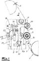
- a strapping device is shown in the figures. With the aid of the strapping device, strapping tape 1 can be guided around objects to be strapped or goods to be strapped, as is known in principle and explained in detail in the prior art already referred to in the introduction.
- the strapping 1 is for this purpose only in the Fig. 1 to be recognized tape supply 2 supplied.
- the strapping device shown only in part, also includes a closure unit 3, which is only indicated here and which is designed as a friction welding unit in the exemplary embodiment and not by way of limitation.
- the closure unit 3 ensures that the ends of the strapping band 1 to be connected to one another are coupled around the goods to be strapped after tensioning, in the present case by friction welding.
- the locking unit 3 can also open Another way to ensure the desired connection of the strap ends of the strap 1.
- the drive motor 4 is a (single) electric motor which, like a step-down or reduction gear 7 to be seen there, and a shaft bearing sleeve 8 are mounted on the rear of a flange 9.
- a gate 10 is also mounted, which will be considered in more detail below.
- the drive motor 4 the gear 7 and the shaft bearing sleeve 8 are each connected to the flange 9 parallel to one another and predominantly perpendicularly upright. This enables an optimal weight distribution to be achieved.
- the attachment of the drive motor 4 "next to" the gear 7 as well as the shaft bearing sleeve 8 ensures that the aforementioned elements 4, 7, 8 require relatively little installation space perpendicular to the flange 9.
- the motor 4 is equipped with a pulley or belt pulley 11 on its output shaft.
- a comparable belt pulley 12 is located on an input shaft of the transmission 7.
- Another belt pulley 13 can also be seen, which is arranged on the input side on a shaft 14 which is mounted within the shaft bearing sleeve 8 and carries the drive roller 5 at the other end.
- the gear 7 is additionally equipped with an integrated brake 15, which, however, is only an option and ensures or can ensure that the gear 7 and with it the tensioning roller 6 attached to its output shaft are stopped after the end of a tensioning process of the strapping band 1.
- the individual belt pulleys 11, 12, 13 are driven by the drive motor 4 via a common movement transmission means 16.
- the movement transmission means 16 is a flexible movement transmission means 16, in the present case a toothed belt.
- the individual belt pulleys 11, 12, 13 in the exemplary embodiment are also designed as toothed belt pulleys and are not restrictive.
- the drive motor 4 ensures that the gear 7 sets the tensioning roller 6 in rotation just as continuously as the drive roller 5 via the shaft bearing sleeve 8 connected in between.
- the previously mentioned pivotable link 10 is provided according to the invention.
- the gate 10 is pivotably connected to the front side of the flange 9.
- the link 10 carries at least two counter rollers 5a, 6a.
- the counter roller 6a belongs to the tensioning roller 6 and is therefore designed as a tensioning counter roller 6a.
- the further counter roller 5a is a drive counter roller 5a which belongs to the drive roller 5, as will be explained in more detail below.
- the gate 10 is overall L-shaped.
- a long L-leg 10a and a short L-leg 10b are implemented.
- the drive counter roller 5a is rotatably connected to the long L-leg 10a and is located approximately in the middle of the long L-leg 10a in question.
- the tensioning counter-roller 6a is rotatably connected to the short L-leg 10b.
- the tensioning counter-roller 6a is located at the end of the short L-leg 10b in question.
- the link 10 can be pivoted slightly to and fro about its pivot point or a pivot bearing 17 formed at this point on the front side of the flange 9, as indicated by a double arrow in FIG Fig. 1 indicates.
- the pivoting angles of the L-shaped gate 10 which are generally located below 20 degrees, and are usually only 10 degrees and less.
- the gate 10 is moved overall against the force of a spring 18, 19.
- a spring 18 belonging to the band tensioning and a further spring 19 are implemented, which primarily have an effect when the strapping band 1 is driven.
- the eccentric 20, 21, 22 is composed in detail of a cam 20 and a cam roller 21, which in turn is rotatably mounted on a cam roller lever 22.
- the cam roller lever 22 has an axis of rotation 23, with the aid of which it is rotatably mounted with respect to the flange 9.
- the strapping 1 is clamped between the tensioning roller 6 and the tensioning counter-roller 6a.
- the link 10 is acted upon in the opposite direction with the aid of the eccentric 20, 21, 22, namely executes a counterclockwise movement in relation to its pivot bearing 17.
- the drive counter roller 5a moves away from the drive roller 5
- Tensioning counter-roller 6a for resting on the tensioning roller 6.
- the strapping band 1 clamped between the two rollers 6, 6a can then be tensioned.
- the tensioned ends of the strap 1 can be connected with the aid of the closure unit 3, as was already described in the introduction.
Landscapes
- Engineering & Computer Science (AREA)
- Mechanical Engineering (AREA)
- Basic Packing Technique (AREA)
Claims (10)
- Dispositif de cerclage avec au moins un moteur d'entraînement (4), avec en plus au moins un rouleau entraîneur (5) pour une bande de cerclage (1) acheminée depuis une réserve de bande (2), ainsi qu'avec au moins un rouleau tendeur (6) pour tendre la bande de cerclage (1) passée autour du matériau à cercler et avec une unité de fermeture (3) pour relier les extrémités de bande de la bande de cerclage (1) passée autour du matériau, sachant qu'
une coulisse pivotable (10) est prévue, laquelle applique au moins un contre-rouleau (5a, 6a) au rouleau entraîneur (5) pour l'entraînement de la bande ou au rouleau tendeur (6) pour la tension de la bande, et sachant que
le moteur d'entraînement (4) veille tant à l'entraînement du rouleau entraîneur (5) que du rouleau tendeur (6),
caractérisé en ce que- la coulisse (10) supporte au moins deux contre-rouleaux (5a, 6a), notamment un contre-rouleau entraîneur (5a) et un contre-rouleau tendeur (6a), en ce qu'en plus- le moteur d'entraînement (4) sollicite le rouleau tendeur (6) par le biais d'une transmission (7) ainsi que le rouleau entraîneur (5) par l'intermédiaire d'un manchon de palier d'arbre (8), et en ce que- la coulisse (10) est logée pouvant tourner sur une bride (9), sachant que- le moteur d'entraînement (4), la transmission (7) et le manchon de palier d'arbre (8) sont raccordés respectivement parallèlement l'un à l'autre et essentiellement dressés perpendiculairement sur la bride (9). - Dispositif de cerclage selon la revendication 1, caractérisé en ce que la bride (9) loge sur sa face avant la coulisse (10) et sur sa face arrière le moteur d'entraînement (4) ainsi que la transmission (7) et le manchon de palier d'arbre (8).
- Dispositif de cerclage selon la revendication 1 ou 2, caractérisé en ce que la coulisse (10) est constituée en forme de L.
- Dispositif de cerclage selon la revendication 3, caractérisé en ce que la coulisse (10) est logée pouvant tourner à l'extrémité de sa branche en L longue (10a).
- Dispositif de cerclage selon la revendication 3 ou 4, caractérisé en ce qu'un contre-rouleau (5a) est logé sur la branche en L longue (10a) et l'autre contre-rouleau (6a) sur la branche en L courte (10b).
- Dispositif de cerclage selon la revendication 5, caractérisé en ce que le contre-rouleau entraîneur (5a) est raccordé à peu près au centre à la branche en L longue (10a).
- Dispositif de cerclage selon l'une quelconque des revendications 4 à 6, caractérisé en ce que le contre-rouleau tendeur (6a) est raccordé à peu près au centre à la branche en L courte (10b).
- Dispositif de cerclage selon l'une quelconque des revendications 1 à 7, caractérisé en ce que la coulisse (10) est déplacée contre la force d'au moins un ressort (18, 19).
- Dispositif de cerclage selon l'une quelconque des revendications 1 à 8, caractérisé en ce qu'un excentrique (20, 21, 22) est prévu pour faire pivoter la coulisse (10).
- Dispositif de cerclage selon la revendication 9, caractérisé en ce que l'excentrique (20, 21, 22) comporte une came (20), laquelle fonctionne par exemple par le biais d'un galet de came (21) et d'un levier de galet de came (22) sur la coulisse (10).
Priority Applications (4)
| Application Number | Priority Date | Filing Date | Title |
|---|---|---|---|
| ES18168243T ES2870996T3 (es) | 2018-04-19 | 2018-04-19 | Dispositivo de zunchado |
| EP18168243.6A EP3556667B1 (fr) | 2018-04-19 | 2018-04-19 | Dispositif de cerclage |
| US16/387,616 US11027866B2 (en) | 2018-04-19 | 2019-04-18 | Strapping apparatus |
| CN201910315309.2A CN110386285B (zh) | 2018-04-19 | 2019-04-19 | 捆扎装置 |
Applications Claiming Priority (1)
| Application Number | Priority Date | Filing Date | Title |
|---|---|---|---|
| EP18168243.6A EP3556667B1 (fr) | 2018-04-19 | 2018-04-19 | Dispositif de cerclage |
Publications (3)
| Publication Number | Publication Date |
|---|---|
| EP3556667A1 EP3556667A1 (fr) | 2019-10-23 |
| EP3556667A8 EP3556667A8 (fr) | 2020-01-08 |
| EP3556667B1 true EP3556667B1 (fr) | 2021-04-14 |
Family
ID=62027874
Family Applications (1)
| Application Number | Title | Priority Date | Filing Date |
|---|---|---|---|
| EP18168243.6A Active EP3556667B1 (fr) | 2018-04-19 | 2018-04-19 | Dispositif de cerclage |
Country Status (4)
| Country | Link |
|---|---|
| US (1) | US11027866B2 (fr) |
| EP (1) | EP3556667B1 (fr) |
| CN (1) | CN110386285B (fr) |
| ES (1) | ES2870996T3 (fr) |
Families Citing this family (1)
| Publication number | Priority date | Publication date | Assignee | Title |
|---|---|---|---|---|
| CN113978791B (zh) * | 2021-11-05 | 2023-01-10 | 北京航星机器制造有限公司 | 一种扎带机 |
Family Cites Families (14)
| Publication number | Priority date | Publication date | Assignee | Title |
|---|---|---|---|---|
| GB885371A (en) * | 1959-04-18 | 1961-12-28 | Ver Metaalverpakking Mij Nv | Machine for securing a metal strap around a container, box, package or the like |
| US3232217A (en) * | 1964-05-04 | 1966-02-01 | Stanley Works | Strapping machine |
| US3536430A (en) * | 1967-11-21 | 1970-10-27 | Ikegai Iron Works Ltd | Automatic strapping machine |
| US4218969A (en) * | 1979-02-01 | 1980-08-26 | Nichiro Kogyo Company, Limited | Band feeding and tightening apparatus for strapping machine |
| GB2041869B (en) | 1979-02-23 | 1982-12-08 | Nichiro Kogyo Kk | Band feeding and tightening method and device for strapping machinqe |
| DE4014307C2 (de) * | 1990-05-04 | 1996-11-07 | Rmo Systempack Gmbh | Packmaschine |
| US5112004A (en) * | 1990-11-07 | 1992-05-12 | Illinois Tool Works Inc. | Strap dispensing and accumulating apparatus and combination of same with strapping machine |
| US5459977A (en) * | 1993-12-09 | 1995-10-24 | Illinois Tool Works Inc. | Method and apparatus for an improved power strapping machine |
| US5377477A (en) * | 1993-12-09 | 1995-01-03 | Signode Corporation | Method and apparatus for a power strapping machine |
| US6155032A (en) * | 1999-09-09 | 2000-12-05 | Lai; Chien-Fa | Automatic wrapper |
| DE102008004118B4 (de) | 2008-01-11 | 2011-04-14 | Maschinenfabrik Gerd Mosca Ag | Umreifungsmaschine mit einem Bandführungskanal und einer Zufuhreinheit |
| PL3105129T3 (pl) * | 2014-02-10 | 2019-07-31 | Orgapack Gmbh | Urządzenie opasujące |
| DE102014105126A1 (de) * | 2014-04-10 | 2015-10-15 | Krones Aktiengesellschaft | Bandantriebseinrichtung einer Umreifungsmaschine |
| CN107842764A (zh) * | 2017-11-17 | 2018-03-27 | 盱眙县生产力促进中心 | 一种物理学科用方便除尘的led灯 |
-
2018
- 2018-04-19 ES ES18168243T patent/ES2870996T3/es active Active
- 2018-04-19 EP EP18168243.6A patent/EP3556667B1/fr active Active
-
2019
- 2019-04-18 US US16/387,616 patent/US11027866B2/en active Active
- 2019-04-19 CN CN201910315309.2A patent/CN110386285B/zh active Active
Also Published As
| Publication number | Publication date |
|---|---|
| US20190322398A1 (en) | 2019-10-24 |
| CN110386285A (zh) | 2019-10-29 |
| EP3556667A1 (fr) | 2019-10-23 |
| CN110386285B (zh) | 2022-07-26 |
| US11027866B2 (en) | 2021-06-08 |
| EP3556667A8 (fr) | 2020-01-08 |
| ES2870996T3 (es) | 2021-10-28 |
Similar Documents
| Publication | Publication Date | Title |
|---|---|---|
| EP0711724B1 (fr) | Dispositif pour séparer des sections tubulaires perforées | |
| CH712984A2 (de) | Umreifungsvorrichtung zur Umreifung von Packgut mit einem Umreifungsband. | |
| EP3105126B1 (fr) | Dispositif de tension pour dispositif de cerclage | |
| EP1074500B1 (fr) | Cylindre de transport de produits d'imprimerie d'un appareil de pliage | |
| DE4344622A1 (de) | Räderfalzapparat für eine Rotationsdruckmaschine | |
| EP3556667B1 (fr) | Dispositif de cerclage | |
| CH629724A5 (de) | Falzmaschine mit einem schwertfalzwerk. | |
| DE1436785A1 (de) | Maschine zum fortlaufenden Herstellen von Flachbeuteln | |
| EP0232553B1 (fr) | Dispositif pour enrouler des objets plats arrivant en formation continue imbriqué | |
| DE2519420A1 (de) | Falzvorrichtung | |
| CH660578A5 (de) | Verfahren und einrichtung zur durchlaufhandhabung von blattfoermigen gegenstaenden. | |
| EP2930116B1 (fr) | Dispositif d'entraînement de bande d'une enrubanneuse | |
| EP0847922B1 (fr) | Dispositif de cerclage de paquets | |
| EP0699786A2 (fr) | Dispositif de formation de la foule | |
| EP3328629B1 (fr) | Dispositif et procédé de fixation d'une partie inférieure ouverte d'une pièce tubulaire | |
| DE3335645C2 (fr) | ||
| DE1436785C (de) | Maschine zum fortlaufenden Herstellen von Flachbeuteln | |
| EP3336019A2 (fr) | Dispositif de transport d'objets et en particulier d'emballages, de caisses à bouteilles et analogues | |
| EP0415272A1 (fr) | Arrangement à un dispositif de cerclage pour tensionner une boucle mise autour d'un objet à cercler | |
| CH709244A2 (de) | Spanneinrichtung einer Umreifungsvorrichtung zur Umreifung von Packgut mit einem Umreifungsband. | |
| CH709245A2 (de) | Umreifungseinrichtung einer Umreifungsvorrichtung zur Umreifung von Packgut mit einem Umreifungsband. | |
| CH686774A5 (de) | Bandklemmeinrichtung. | |
| DE19936842A1 (de) | Exemplarführender Zylinder eines Falzapparates | |
| CH709246A2 (de) | Umreifungseinrichtung einer Umreifungsvorrichtung zur Umreifung von Packgut mit einem Umreifungsband. | |
| DE1271035B (de) | Beschickungsvorrichtung zum Abstreifen von zerkleinertem Gut von einem Boden auf einFoerderband |
Legal Events
| Date | Code | Title | Description |
|---|---|---|---|
| PUAI | Public reference made under article 153(3) epc to a published international application that has entered the european phase |
Free format text: ORIGINAL CODE: 0009012 |
|
| STAA | Information on the status of an ep patent application or granted ep patent |
Free format text: STATUS: THE APPLICATION HAS BEEN PUBLISHED |
|
| AK | Designated contracting states |
Kind code of ref document: A1 Designated state(s): AL AT BE BG CH CY CZ DE DK EE ES FI FR GB GR HR HU IE IS IT LI LT LU LV MC MK MT NL NO PL PT RO RS SE SI SK SM TR |
|
| AX | Request for extension of the european patent |
Extension state: BA ME |
|
| RIN1 | Information on inventor provided before grant (corrected) |
Inventor name: ANDREAS, BJOERN Inventor name: NEUMANN, FRANK |
|
| STAA | Information on the status of an ep patent application or granted ep patent |
Free format text: STATUS: REQUEST FOR EXAMINATION WAS MADE |
|
| 17P | Request for examination filed |
Effective date: 20200304 |
|
| RBV | Designated contracting states (corrected) |
Designated state(s): AL AT BE BG CH CY CZ DE DK EE ES FI FR GB GR HR HU IE IS IT LI LT LU LV MC MK MT NL NO PL PT RO RS SE SI SK SM TR |
|
| GRAP | Despatch of communication of intention to grant a patent |
Free format text: ORIGINAL CODE: EPIDOSNIGR1 |
|
| STAA | Information on the status of an ep patent application or granted ep patent |
Free format text: STATUS: GRANT OF PATENT IS INTENDED |
|
| GRAS | Grant fee paid |
Free format text: ORIGINAL CODE: EPIDOSNIGR3 |
|
| INTG | Intention to grant announced |
Effective date: 20210119 |
|
| GRAA | (expected) grant |
Free format text: ORIGINAL CODE: 0009210 |
|
| STAA | Information on the status of an ep patent application or granted ep patent |
Free format text: STATUS: THE PATENT HAS BEEN GRANTED |
|
| AK | Designated contracting states |
Kind code of ref document: B1 Designated state(s): AL AT BE BG CH CY CZ DE DK EE ES FI FR GB GR HR HU IE IS IT LI LT LU LV MC MK MT NL NO PL PT RO RS SE SI SK SM TR |
|
| REG | Reference to a national code |
Ref country code: GB Ref legal event code: FG4D Free format text: NOT ENGLISH |
|
| REG | Reference to a national code |
Ref country code: CH Ref legal event code: EP |
|
| REG | Reference to a national code |
Ref country code: DE Ref legal event code: R096 Ref document number: 502018004754 Country of ref document: DE |
|
| REG | Reference to a national code |
Ref country code: IE Ref legal event code: FG4D Free format text: LANGUAGE OF EP DOCUMENT: GERMAN |
|
| REG | Reference to a national code |
Ref country code: AT Ref legal event code: REF Ref document number: 1382171 Country of ref document: AT Kind code of ref document: T Effective date: 20210515 |
|
| REG | Reference to a national code |
Ref country code: LT Ref legal event code: MG9D |
|
| REG | Reference to a national code |
Ref country code: NL Ref legal event code: MP Effective date: 20210414 |
|
| REG | Reference to a national code |
Ref country code: ES Ref legal event code: FG2A Ref document number: 2870996 Country of ref document: ES Kind code of ref document: T3 Effective date: 20211028 |
|
| PG25 | Lapsed in a contracting state [announced via postgrant information from national office to epo] |
Ref country code: NL Free format text: LAPSE BECAUSE OF FAILURE TO SUBMIT A TRANSLATION OF THE DESCRIPTION OR TO PAY THE FEE WITHIN THE PRESCRIBED TIME-LIMIT Effective date: 20210414 Ref country code: BG Free format text: LAPSE BECAUSE OF FAILURE TO SUBMIT A TRANSLATION OF THE DESCRIPTION OR TO PAY THE FEE WITHIN THE PRESCRIBED TIME-LIMIT Effective date: 20210714 Ref country code: HR Free format text: LAPSE BECAUSE OF FAILURE TO SUBMIT A TRANSLATION OF THE DESCRIPTION OR TO PAY THE FEE WITHIN THE PRESCRIBED TIME-LIMIT Effective date: 20210414 Ref country code: LT Free format text: LAPSE BECAUSE OF FAILURE TO SUBMIT A TRANSLATION OF THE DESCRIPTION OR TO PAY THE FEE WITHIN THE PRESCRIBED TIME-LIMIT Effective date: 20210414 Ref country code: FI Free format text: LAPSE BECAUSE OF FAILURE TO SUBMIT A TRANSLATION OF THE DESCRIPTION OR TO PAY THE FEE WITHIN THE PRESCRIBED TIME-LIMIT Effective date: 20210414 |
|
| PG25 | Lapsed in a contracting state [announced via postgrant information from national office to epo] |
Ref country code: GR Free format text: LAPSE BECAUSE OF FAILURE TO SUBMIT A TRANSLATION OF THE DESCRIPTION OR TO PAY THE FEE WITHIN THE PRESCRIBED TIME-LIMIT Effective date: 20210715 Ref country code: IS Free format text: LAPSE BECAUSE OF FAILURE TO SUBMIT A TRANSLATION OF THE DESCRIPTION OR TO PAY THE FEE WITHIN THE PRESCRIBED TIME-LIMIT Effective date: 20210814 Ref country code: LV Free format text: LAPSE BECAUSE OF FAILURE TO SUBMIT A TRANSLATION OF THE DESCRIPTION OR TO PAY THE FEE WITHIN THE PRESCRIBED TIME-LIMIT Effective date: 20210414 Ref country code: PT Free format text: LAPSE BECAUSE OF FAILURE TO SUBMIT A TRANSLATION OF THE DESCRIPTION OR TO PAY THE FEE WITHIN THE PRESCRIBED TIME-LIMIT Effective date: 20210816 Ref country code: NO Free format text: LAPSE BECAUSE OF FAILURE TO SUBMIT A TRANSLATION OF THE DESCRIPTION OR TO PAY THE FEE WITHIN THE PRESCRIBED TIME-LIMIT Effective date: 20210714 Ref country code: PL Free format text: LAPSE BECAUSE OF FAILURE TO SUBMIT A TRANSLATION OF THE DESCRIPTION OR TO PAY THE FEE WITHIN THE PRESCRIBED TIME-LIMIT Effective date: 20210414 Ref country code: RS Free format text: LAPSE BECAUSE OF FAILURE TO SUBMIT A TRANSLATION OF THE DESCRIPTION OR TO PAY THE FEE WITHIN THE PRESCRIBED TIME-LIMIT Effective date: 20210414 Ref country code: SE Free format text: LAPSE BECAUSE OF FAILURE TO SUBMIT A TRANSLATION OF THE DESCRIPTION OR TO PAY THE FEE WITHIN THE PRESCRIBED TIME-LIMIT Effective date: 20210414 |
|
| PG25 | Lapsed in a contracting state [announced via postgrant information from national office to epo] |
Ref country code: LU Free format text: LAPSE BECAUSE OF NON-PAYMENT OF DUE FEES Effective date: 20210419 |
|
| REG | Reference to a national code |
Ref country code: DE Ref legal event code: R097 Ref document number: 502018004754 Country of ref document: DE |
|
| REG | Reference to a national code |
Ref country code: BE Ref legal event code: MM Effective date: 20210430 |
|
| PG25 | Lapsed in a contracting state [announced via postgrant information from national office to epo] |
Ref country code: SM Free format text: LAPSE BECAUSE OF FAILURE TO SUBMIT A TRANSLATION OF THE DESCRIPTION OR TO PAY THE FEE WITHIN THE PRESCRIBED TIME-LIMIT Effective date: 20210414 Ref country code: SK Free format text: LAPSE BECAUSE OF FAILURE TO SUBMIT A TRANSLATION OF THE DESCRIPTION OR TO PAY THE FEE WITHIN THE PRESCRIBED TIME-LIMIT Effective date: 20210414 Ref country code: EE Free format text: LAPSE BECAUSE OF FAILURE TO SUBMIT A TRANSLATION OF THE DESCRIPTION OR TO PAY THE FEE WITHIN THE PRESCRIBED TIME-LIMIT Effective date: 20210414 Ref country code: RO Free format text: LAPSE BECAUSE OF FAILURE TO SUBMIT A TRANSLATION OF THE DESCRIPTION OR TO PAY THE FEE WITHIN THE PRESCRIBED TIME-LIMIT Effective date: 20210414 Ref country code: CH Free format text: LAPSE BECAUSE OF NON-PAYMENT OF DUE FEES Effective date: 20210430 Ref country code: CZ Free format text: LAPSE BECAUSE OF FAILURE TO SUBMIT A TRANSLATION OF THE DESCRIPTION OR TO PAY THE FEE WITHIN THE PRESCRIBED TIME-LIMIT Effective date: 20210414 Ref country code: DK Free format text: LAPSE BECAUSE OF FAILURE TO SUBMIT A TRANSLATION OF THE DESCRIPTION OR TO PAY THE FEE WITHIN THE PRESCRIBED TIME-LIMIT Effective date: 20210414 Ref country code: LI Free format text: LAPSE BECAUSE OF NON-PAYMENT OF DUE FEES Effective date: 20210430 Ref country code: MC Free format text: LAPSE BECAUSE OF FAILURE TO SUBMIT A TRANSLATION OF THE DESCRIPTION OR TO PAY THE FEE WITHIN THE PRESCRIBED TIME-LIMIT Effective date: 20210414 |
|
| PLBE | No opposition filed within time limit |
Free format text: ORIGINAL CODE: 0009261 |
|
| STAA | Information on the status of an ep patent application or granted ep patent |
Free format text: STATUS: NO OPPOSITION FILED WITHIN TIME LIMIT |
|
| 26N | No opposition filed |
Effective date: 20220117 |
|
| PG25 | Lapsed in a contracting state [announced via postgrant information from national office to epo] |
Ref country code: IE Free format text: LAPSE BECAUSE OF NON-PAYMENT OF DUE FEES Effective date: 20210419 |
|
| PG25 | Lapsed in a contracting state [announced via postgrant information from national office to epo] |
Ref country code: IS Free format text: LAPSE BECAUSE OF FAILURE TO SUBMIT A TRANSLATION OF THE DESCRIPTION OR TO PAY THE FEE WITHIN THE PRESCRIBED TIME-LIMIT Effective date: 20210814 Ref country code: FR Free format text: LAPSE BECAUSE OF NON-PAYMENT OF DUE FEES Effective date: 20210614 Ref country code: AL Free format text: LAPSE BECAUSE OF FAILURE TO SUBMIT A TRANSLATION OF THE DESCRIPTION OR TO PAY THE FEE WITHIN THE PRESCRIBED TIME-LIMIT Effective date: 20210414 |
|
| PG25 | Lapsed in a contracting state [announced via postgrant information from national office to epo] |
Ref country code: BE Free format text: LAPSE BECAUSE OF NON-PAYMENT OF DUE FEES Effective date: 20210430 |
|
| GBPC | Gb: european patent ceased through non-payment of renewal fee |
Effective date: 20220419 |
|
| PG25 | Lapsed in a contracting state [announced via postgrant information from national office to epo] |
Ref country code: GB Free format text: LAPSE BECAUSE OF NON-PAYMENT OF DUE FEES Effective date: 20220419 |
|
| PG25 | Lapsed in a contracting state [announced via postgrant information from national office to epo] |
Ref country code: CY Free format text: LAPSE BECAUSE OF FAILURE TO SUBMIT A TRANSLATION OF THE DESCRIPTION OR TO PAY THE FEE WITHIN THE PRESCRIBED TIME-LIMIT Effective date: 20210414 |
|
| PG25 | Lapsed in a contracting state [announced via postgrant information from national office to epo] |
Ref country code: HU Free format text: LAPSE BECAUSE OF FAILURE TO SUBMIT A TRANSLATION OF THE DESCRIPTION OR TO PAY THE FEE WITHIN THE PRESCRIBED TIME-LIMIT; INVALID AB INITIO Effective date: 20180419 |
|
| PGFP | Annual fee paid to national office [announced via postgrant information from national office to epo] |
Ref country code: IT Payment date: 20230426 Year of fee payment: 6 Ref country code: ES Payment date: 20230627 Year of fee payment: 6 Ref country code: DE Payment date: 20230329 Year of fee payment: 6 |
|
| PGFP | Annual fee paid to national office [announced via postgrant information from national office to epo] |
Ref country code: AT Payment date: 20230420 Year of fee payment: 6 |
|
| PG25 | Lapsed in a contracting state [announced via postgrant information from national office to epo] |
Ref country code: MK Free format text: LAPSE BECAUSE OF FAILURE TO SUBMIT A TRANSLATION OF THE DESCRIPTION OR TO PAY THE FEE WITHIN THE PRESCRIBED TIME-LIMIT Effective date: 20210414 |