US8522678B2 - Strapping machine having a movable working assembly - Google Patents
Strapping machine having a movable working assembly Download PDFInfo
- Publication number
- US8522678B2 US8522678B2 US13/034,676 US201113034676A US8522678B2 US 8522678 B2 US8522678 B2 US 8522678B2 US 201113034676 A US201113034676 A US 201113034676A US 8522678 B2 US8522678 B2 US 8522678B2
- Authority
- US
- United States
- Prior art keywords
- move
- working
- movable
- rod
- chute
- Prior art date
- Legal status (The legal status is an assumption and is not a legal conclusion. Google has not performed a legal analysis and makes no representation as to the accuracy of the status listed.)
- Active, expires
Links
Images


Classifications
-
- B—PERFORMING OPERATIONS; TRANSPORTING
- B65—CONVEYING; PACKING; STORING; HANDLING THIN OR FILAMENTARY MATERIAL
- B65B—MACHINES, APPARATUS OR DEVICES FOR, OR METHODS OF, PACKAGING ARTICLES OR MATERIALS; UNPACKING
- B65B59/00—Arrangements to enable machines to handle articles of different sizes, to produce packages of different sizes, to vary the contents of packages, to handle different types of packaging material, or to give access for cleaning or maintenance purposes
- B65B59/04—Machines constructed with readily-detachable units or assemblies, e.g. to facilitate maintenance
-
- B—PERFORMING OPERATIONS; TRANSPORTING
- B65—CONVEYING; PACKING; STORING; HANDLING THIN OR FILAMENTARY MATERIAL
- B65B—MACHINES, APPARATUS OR DEVICES FOR, OR METHODS OF, PACKAGING ARTICLES OR MATERIALS; UNPACKING
- B65B13/00—Bundling articles
- B65B13/02—Applying and securing binding material around articles or groups of articles, e.g. using strings, wires, strips, bands or tapes
- B65B13/04—Applying and securing binding material around articles or groups of articles, e.g. using strings, wires, strips, bands or tapes with means for guiding the binding material around the articles prior to severing from supply
- B65B13/06—Stationary ducts or channels
-
- B—PERFORMING OPERATIONS; TRANSPORTING
- B65—CONVEYING; PACKING; STORING; HANDLING THIN OR FILAMENTARY MATERIAL
- B65B—MACHINES, APPARATUS OR DEVICES FOR, OR METHODS OF, PACKAGING ARTICLES OR MATERIALS; UNPACKING
- B65B13/00—Bundling articles
- B65B13/18—Details of, or auxiliary devices used in, bundling machines or bundling tools
- B65B13/185—Details of tools
Definitions
- the present invention relates a strapping machine having a movable working assembly. Particularly, it relates to a strapping machine having a movable working assembly for easy maintenance. In which, it is quick and easy to repair any internal device or part inside the strapping machine. The repairer does not need to stoop or squat down for repairing it. In addition, it saves strength and time to move out the working device or related part.
- the traditional strapping machine includes a base 91 , a chute frame 92 , a sealing/cutting mechanism 93 , and a strap supply 94 .
- a maintenance door 95 disposed on the base 91 for a user (or a repairer) to replace a new strap, to inspect the machine, or to repair some parts.
- the function of this sealing/cutting mechanism 93 is to provide a strap (from the strap supply 94 to the chute frame 92 ) surrounding an object (not shown) and then to proceed the retreating, cutting, and heat sealing actions.
- the sealing/cutting mechanism 93 is very complicated. It includes many internal parts, such as guiding rollers, electric motors, guiding rails, electric heater, controlling circuits, etc (these parts are omitted or simplified in the related figures). Once any internal part has a breakdown during operation, the user has to open the maintenance door 95 and then to squat down with stretching one's hand inside the machine for inspection. Therefore, the traditional one has the following drawbacks and problems:
- the repairer has to stoop or squat down for repairing it. Because the user (or the repairer) has to stoop or squat down to reach the sealing/cutting mechanism 93 inside the base 91 (or other parts), its working efficiency is very low and it tends to cause the user's back pain or long-term poor posture related pain.
- the objects of the present invention are to provide a strapping machine having a movable working assembly.
- it is quick and easy to repair any internal device or part inside the strapping machine.
- the repairer does not need to stoop or squat down for repairing it.
- this invention can solve the problems of the traditional one listed as follows. It is difficult to repair the internal devices or parts inside the traditional strapping machine.
- the repairer has to stoop or squat down for repairing it. Plus, it cannot take the sealing/cutting mechanism out.
- a strapping machine having a movable working assembly comprising:
- a machine body including a controller, a working deck, a storing space, a door, and a horizontal securing portion, the working deck having a working opening, the storing space being beneath the working deck, the door being able to be opened so as to allow the storing space communicating with an external space; the horizontal securing portion being positioned in the storing space;
- a chute having an upper chute portion and a lower chute portion, the upper chute portion being secured on the machine body;
- a movable working assembly including:
- a horizontal movable portion having a horizontal moving portion and a vertical moving base; the horizontal moving portion connecting with the horizontal securing portion and having at least a move-in position and a move-out position;
- a vertical movable portion having a vertical moving portion and a working device supporting portion; the vertical movable portion which connects with the vertical moving base being movable on the horizontal movable portion vertically and being movable between a move-up position and a move-down position; when the vertical movable portion moving to the move-down position, the lower chute portion being separated from the upper chute portion and the lower chute portion of the chute being not blocked by the working deck; when the vertical movable portion moving to the move-up position, the upper chute portion and the lower chute portion being combined as a loop for guiding a strap to surround a working object;
- an operation linkage mechanism having a first rod, a central shaft portion, a second rod, and a central pivoting seat; the second rod connecting to the vertical movable portion, the central pivoting portion being pivoted with the central shaft portion; the first rod, the central shaft portion and the second rod being connected as an integral body; when the first rod being moved, the second rod being moved accordingly, so as to control the vertical movable portion moving between the move-up position and the move-down position;
- the first rod is able to be rotated down so that the vertical movable portion moves from the move-up position to the move-down position, and then the horizontal movable portion is able to be moved from the move-in position to the move-out portion so as to make the working device is moved out from the storing space for easy maintenance.
- FIG. 1 is a perspective view of the present invention.
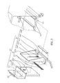
- FIG. 2 is an exploded view of a portion of the present invention.
- FIG. 3A is a view showing that the movable working assembly is inside.
- FIG. 3B is a view showing that the first rod is rotated down.
- FIG. 3C is a view showing that the movable working assembly can be moved out.
- FIG. 4A illustrates the lower chute portion which is kept at the move-up position.
- FIG. 4B illustrates the lower chute portion moved to the move-down position.
- FIG. 5 is a view showing a traditional strapping machine.
- FIG. 6 is a perspective view of the traditional strapping machine.
- the present invention relates to a strapping machine having a movable working assembly. It mainly comprises a machine body 10 , a chute 20 , a movable working assembly 30 .
- said machine body 10 includes a controller 11 , a working deck 12 , a storing space 13 , a door 14 , and a horizontal securing portion 15 .
- This working deck 12 has a working opening 121 .
- the storing space 13 is beneath the working deck 12 .
- the door 14 is able to be opened so as to allow the storing space 13 communicating with an external space.
- the horizontal securing portion 15 is positioned in the storing space 13 .
- the chute 20 it has an upper chute portion 21 and a lower chute portion 22 .
- the upper chute portion 21 is secured on the machine body 10 .
- the movable working assembly 30 includes a horizontal movable portion 31 , a vertical movable portion 32 , a working device 33 , and an operation linkage mechanism 34 .
- the horizontal movable portion 31 has a horizontal moving portion 311 and a vertical moving base 312 .
- the horizontal moving portion 311 connects with the horizontal securing portion 15 so that the horizontal movable portion 31 can be moved on the machine body 10 horizontally.
- the horizontal moving portion 311 has at least a move-in position P 1 and a move-out position P 2 (as illustrated in FIG. 3 C).
- a vertical movable portion 32 has a vertical moving portion 321 and a working device supporting portion 322 .
- the vertical movable portion 32 which connects with the vertical moving base 312 is movable on the horizontal movable portion 31 vertically. Plus, the vertical movable portion 32 is movable between a move-up position P 3 and a move-down position P 4 (referring to FIGS. 3A and 3B ).
- the vertical movable portion 32 moves to the move-down position P 4 , the lower chute portion 22 of the chute 20 is separated from the upper chute portion 21 , and the lower chute portion 22 of the chute 20 is not blocked by the working deck 12 .
- the upper chute portion 21 and the lower chute portion 22 are combined together as a loop for guiding a strap to surround a working object.
- the working device 33 is fixed on the working device supporting portion 322 for guiding the strap into the chute 20 and for proceeding a strap retracting action, a strap cutting action, a strap sealing action, and the like.
- the lower chute portion 22 of the chute 20 is mounted on a predetermined position of the working device 33 .
- An operation linkage mechanism 34 has a first rod 341 , a central shaft portion 342 , a second rod 343 , and a central pivoting seat 344 .
- the second rod 343 connects to the vertical movable portion 32 .
- the central pivoting portion 342 is pivoted with the central shaft portion 342 .
- the first rod 341 , the central shaft portion 342 and the second rod 343 are connected as an integral body.
- the operation linkage mechanism 34 can further include a locking portion 34 .
- the locking portion 34 can lock the first rod 341 at the move-up position P 3 .
- the first rod 341 is able to be rotated down so that the vertical movable portion 32 moves from the move-up position P 3 to the move-down position P 4 (as shown in FIGS. 3B , 4 A and 4 B). Then, this horizontal movable portion 31 is able to be moved from the move-in position P 1 to the move-out portion P 2 (as illustrated in FIG. 3C ) so as to make the working device 33 is moved out from the storing space 13 for easy maintenance.
- the present invention has a moveable working assembly which can be moved vertically and horizontally.
- the user can open the door 14 and then rotate the vertical movable portion 32 of the movable working assembly 30 down. After which, the horizontal movable portion 31 can be moved out horizontally. Therefore, it is very easy to repair, inspection, or replacement. Thus, it is quick and easy to repair any internal device or part inside the strapping machine.
- the repairer does not need to stoop or squat down for repairing it. Because the movable working assembly 30 can be lowered down and then be moved out horizontally, the height of the movable working assembly 30 will be roughly around one-third to on half of a repairer who has an average height. Thus, the repairer does not need to stoop or squat down for repairing it.
- the length of the first rod 341 of the operation linkage mechanism 34 is longer, it will save more strength during operation.
- the entire vertical movable portion 32 and the working device 33 can be move up easily. Its operation is quick and not painful.
Landscapes
- Engineering & Computer Science (AREA)
- Mechanical Engineering (AREA)
- Basic Packing Technique (AREA)
Abstract
Description
Claims (1)
Priority Applications (1)
| Application Number | Priority Date | Filing Date | Title |
|---|---|---|---|
| US13/034,676 US8522678B2 (en) | 2011-02-24 | 2011-02-24 | Strapping machine having a movable working assembly |
Applications Claiming Priority (1)
| Application Number | Priority Date | Filing Date | Title |
|---|---|---|---|
| US13/034,676 US8522678B2 (en) | 2011-02-24 | 2011-02-24 | Strapping machine having a movable working assembly |
Publications (2)
| Publication Number | Publication Date |
|---|---|
| US20120216688A1 US20120216688A1 (en) | 2012-08-30 |
| US8522678B2 true US8522678B2 (en) | 2013-09-03 |
Family
ID=46718113
Family Applications (1)
| Application Number | Title | Priority Date | Filing Date |
|---|---|---|---|
| US13/034,676 Active 2031-09-21 US8522678B2 (en) | 2011-02-24 | 2011-02-24 | Strapping machine having a movable working assembly |
Country Status (1)
| Country | Link |
|---|---|
| US (1) | US8522678B2 (en) |
Cited By (1)
| Publication number | Priority date | Publication date | Assignee | Title |
|---|---|---|---|---|
| USD874897S1 (en) | 2017-03-28 | 2020-02-11 | Signode Industrial Group Llc | Strapping device |
Families Citing this family (7)
| Publication number | Priority date | Publication date | Assignee | Title |
|---|---|---|---|---|
| CH705743A2 (en) | 2011-11-14 | 2013-05-15 | Illinois Tool Works | Strapper. |
| US10279945B2 (en) | 2012-10-22 | 2019-05-07 | Encore Packaging Llc | Stretch film roping |
| CN103144799B (en) * | 2013-03-19 | 2015-03-18 | 苏州雪诺机械制造有限公司 | Adhesive-tape type carton sealing machine |
| WO2015117255A1 (en) | 2014-02-10 | 2015-08-13 | Orgapack Gmbh | Strapping apparatus |
| US10843827B2 (en) | 2016-11-06 | 2020-11-24 | Encore Packaging Llc | Stretch film processing to replace strapping |
| USD833493S1 (en) * | 2017-07-14 | 2018-11-13 | Encore Packaging Llc | Stretch strapping device |
| US11673710B2 (en) | 2021-01-14 | 2023-06-13 | Encore Packaging Llc | Securing apparatus for packaging and shipping |
Citations (7)
| Publication number | Priority date | Publication date | Assignee | Title |
|---|---|---|---|---|
| US4412484A (en) * | 1982-08-16 | 1983-11-01 | General Motors Corporation | Strapping machine |
| US4951562A (en) * | 1989-03-16 | 1990-08-28 | Signode Corporation | Strapping machine for compressible loads |
| US6904841B2 (en) * | 2003-06-17 | 2005-06-14 | Illinois Tool Works, Inc. | Strapping machine with adjustable height work surface |
| US6951170B2 (en) * | 2003-06-17 | 2005-10-04 | Illinois Tool Works, Inc. | Strapping machine with improved chute release system |
| US6990895B2 (en) * | 2003-09-10 | 2006-01-31 | Illinois Tool Works, Inc. | Side seal strapping machine |
| US7421944B1 (en) * | 2008-03-27 | 2008-09-09 | Illinois Tool Works Inc. | Strap joint rotator with pivoting linkage and pinch wheel |
| US7428865B1 (en) * | 2007-09-24 | 2008-09-30 | Illinois Tool Works Inc. | Press-type strapping machine |
-
2011
- 2011-02-24 US US13/034,676 patent/US8522678B2/en active Active
Patent Citations (7)
| Publication number | Priority date | Publication date | Assignee | Title |
|---|---|---|---|---|
| US4412484A (en) * | 1982-08-16 | 1983-11-01 | General Motors Corporation | Strapping machine |
| US4951562A (en) * | 1989-03-16 | 1990-08-28 | Signode Corporation | Strapping machine for compressible loads |
| US6904841B2 (en) * | 2003-06-17 | 2005-06-14 | Illinois Tool Works, Inc. | Strapping machine with adjustable height work surface |
| US6951170B2 (en) * | 2003-06-17 | 2005-10-04 | Illinois Tool Works, Inc. | Strapping machine with improved chute release system |
| US6990895B2 (en) * | 2003-09-10 | 2006-01-31 | Illinois Tool Works, Inc. | Side seal strapping machine |
| US7428865B1 (en) * | 2007-09-24 | 2008-09-30 | Illinois Tool Works Inc. | Press-type strapping machine |
| US7421944B1 (en) * | 2008-03-27 | 2008-09-09 | Illinois Tool Works Inc. | Strap joint rotator with pivoting linkage and pinch wheel |
Cited By (5)
| Publication number | Priority date | Publication date | Assignee | Title |
|---|---|---|---|---|
| USD889229S1 (en) | 2017-01-30 | 2020-07-07 | Signode Industrial Group Llc | Strapping device |
| USD904151S1 (en) | 2017-01-30 | 2020-12-08 | Signode Industrial Group Llc | Strapping device |
| USD917997S1 (en) | 2017-01-30 | 2021-05-04 | Signode Industrial Group Llc | Strapping device |
| USD928577S1 (en) | 2017-01-30 | 2021-08-24 | Signode Industrial Group Llc | Strapping device |
| USD874897S1 (en) | 2017-03-28 | 2020-02-11 | Signode Industrial Group Llc | Strapping device |
Also Published As
| Publication number | Publication date |
|---|---|
| US20120216688A1 (en) | 2012-08-30 |
Similar Documents
| Publication | Publication Date | Title |
|---|---|---|
| US8522678B2 (en) | Strapping machine having a movable working assembly | |
| US9561826B2 (en) | Device for opening and closing the engine hood of a construction machine | |
| US20180030766A1 (en) | Door hinge assembly | |
| CN209151972U (en) | A kind of loach breeding loach oviposition device | |
| CN205321774U (en) | Multi -functional TV bench that fish bowl was viewed and admired in area | |
| CN105422489B (en) | A kind of folded fan | |
| CN206864903U (en) | A kind of ring main unit | |
| CN206107086U (en) | A telescopic expansion bed for car as a house | |
| CN206757284U (en) | A kind of office's projection arrangement | |
| CN205877376U (en) | Controllable valve manipulator of remote intelligent | |
| CN206952410U (en) | A kind of ultracapacitor seal welding equipment | |
| CN106723801A (en) | A kind of draw-bar box | |
| CN104382390B (en) | A kind of multifunctional intellectual hangs cabinet | |
| CN108433382B (en) | A kind of construction drawing aeration type protection storing unit | |
| CN215127226U (en) | Embedded electric pressure cooker cover opening and closing device | |
| CN208715098U (en) | A kind of sharing structure of automobile article shading curtain and board putting things | |
| CN110159125A (en) | A kind of chamber door locking unlatching integrated mechanism | |
| CN208305573U (en) | A kind of clamp locking mechanism | |
| CN206989315U (en) | A kind of Multi-storey villa hot water circuit remote control | |
| CN209280555U (en) | A kind of Atomic Absorption Spectrometer portable unit | |
| CN207728166U (en) | The door lock assembly of tea twisting machine blanking door | |
| CN209464444U (en) | A kind of Medical Robot with liquid nitrogen therapy and supplemental oxygen function | |
| CN207268670U (en) | Dish-washing machine switch gate test device | |
| CN207908187U (en) | A kind of random sampling apparatus of corn | |
| CN209523588U (en) | A kind of second open system of moxa-moxibustion cabin hatchcover |
Legal Events
| Date | Code | Title | Description |
|---|---|---|---|
| AS | Assignment |
Owner name: TRANSPAK EQUIPMENT CORPORATION, TAIWAN Free format text: ASSIGNMENT OF ASSIGNORS INTEREST;ASSIGNORS:LIU, CHIN-CHANG;SU, CHI-JAN;REEL/FRAME:025864/0549 Effective date: 20110103 Owner name: TEKPAK CORPORATION, TAIWAN Free format text: ASSIGNMENT OF ASSIGNORS INTEREST;ASSIGNORS:LIU, CHIN-CHANG;SU, CHI-JAN;REEL/FRAME:025864/0549 Effective date: 20110103 |
|
| STCF | Information on status: patent grant |
Free format text: PATENTED CASE |
|
| FPAY | Fee payment |
Year of fee payment: 4 |
|
| MAFP | Maintenance fee payment |
Free format text: PAYMENT OF MAINTENANCE FEE, 8TH YR, SMALL ENTITY (ORIGINAL EVENT CODE: M2552); ENTITY STATUS OF PATENT OWNER: SMALL ENTITY Year of fee payment: 8 |
|
| AS | Assignment |
Owner name: TEKPAK CORPORATION, TAIWAN Free format text: ASSIGNMENT OF ASSIGNORS INTEREST;ASSIGNORS:TEKPAK CORPORATION;TRANSPAK EQUIPMENT CORPORATION;REEL/FRAME:068201/0723 Effective date: 20240801 |
|
| AS | Assignment |
Owner name: TRANSPAK EQUIPMENT CORPORATION, TAIWAN Free format text: CHANGE OF NAME;ASSIGNOR:TEKPAK CORPORATION;REEL/FRAME:069350/0687 Effective date: 20240809 |
|
| MAFP | Maintenance fee payment |
Free format text: PAYMENT OF MAINTENANCE FEE, 12TH YR, SMALL ENTITY (ORIGINAL EVENT CODE: M2553); ENTITY STATUS OF PATENT OWNER: SMALL ENTITY Year of fee payment: 12 |