EP3105128B1 - Umreifungseinrichtung mit einer bandvorschubeinrichtung - Google Patents
Umreifungseinrichtung mit einer bandvorschubeinrichtung Download PDFInfo
- Publication number
- EP3105128B1 EP3105128B1 EP15711037.0A EP15711037A EP3105128B1 EP 3105128 B1 EP3105128 B1 EP 3105128B1 EP 15711037 A EP15711037 A EP 15711037A EP 3105128 B1 EP3105128 B1 EP 3105128B1
- Authority
- EP
- European Patent Office
- Prior art keywords
- strapping
- wheel
- band
- wheels
- movement
- Prior art date
- Legal status (The legal status is an assumption and is not a legal conclusion. Google has not performed a legal analysis and makes no representation as to the accuracy of the status listed.)
- Active
Links
- 230000033001 locomotion Effects 0.000 claims description 120
- 230000015572 biosynthetic process Effects 0.000 claims description 16
- 238000001514 detection method Methods 0.000 claims description 6
- 229920003023 plastic Polymers 0.000 claims description 4
- 239000004033 plastic Substances 0.000 claims description 4
- 230000008878 coupling Effects 0.000 claims description 3
- 238000010168 coupling process Methods 0.000 claims description 3
- 238000005859 coupling reaction Methods 0.000 claims description 3
- 230000001419 dependent effect Effects 0.000 claims 1
- 238000000034 method Methods 0.000 description 45
- 230000008569 process Effects 0.000 description 45
- 238000009423 ventilation Methods 0.000 description 28
- 238000005755 formation reaction Methods 0.000 description 14
- 230000005540 biological transmission Effects 0.000 description 9
- 230000002441 reversible effect Effects 0.000 description 8
- 230000006835 compression Effects 0.000 description 7
- 238000007906 compression Methods 0.000 description 7
- 238000003825 pressing Methods 0.000 description 7
- 230000000694 effects Effects 0.000 description 6
- 125000006850 spacer group Chemical group 0.000 description 5
- 238000013022 venting Methods 0.000 description 5
- 238000005452 bending Methods 0.000 description 4
- 230000007246 mechanism Effects 0.000 description 4
- 238000012546 transfer Methods 0.000 description 3
- 230000008901 benefit Effects 0.000 description 2
- 238000006243 chemical reaction Methods 0.000 description 2
- 230000007257 malfunction Effects 0.000 description 2
- 239000007769 metal material Substances 0.000 description 2
- 230000002093 peripheral effect Effects 0.000 description 2
- 230000004044 response Effects 0.000 description 2
- 238000003860 storage Methods 0.000 description 2
- 230000000712 assembly Effects 0.000 description 1
- 238000000429 assembly Methods 0.000 description 1
- 230000004888 barrier function Effects 0.000 description 1
- 230000008859 change Effects 0.000 description 1
- 230000005465 channeling Effects 0.000 description 1
- 239000003795 chemical substances by application Substances 0.000 description 1
- 238000005520 cutting process Methods 0.000 description 1
- 230000007423 decrease Effects 0.000 description 1
- 238000013461 design Methods 0.000 description 1
- 238000011161 development Methods 0.000 description 1
- 238000006073 displacement reaction Methods 0.000 description 1
- 239000013013 elastic material Substances 0.000 description 1
- 230000002349 favourable effect Effects 0.000 description 1
- 238000009434 installation Methods 0.000 description 1
- 239000000463 material Substances 0.000 description 1
- 230000013011 mating Effects 0.000 description 1
- 239000002184 metal Substances 0.000 description 1
- 230000009467 reduction Effects 0.000 description 1
- 230000000284 resting effect Effects 0.000 description 1
- 238000007788 roughening Methods 0.000 description 1
- 238000007789 sealing Methods 0.000 description 1
- 230000002123 temporal effect Effects 0.000 description 1
- 238000003466 welding Methods 0.000 description 1
Images


Classifications
-
- B—PERFORMING OPERATIONS; TRANSPORTING
- B65—CONVEYING; PACKING; STORING; HANDLING THIN OR FILAMENTARY MATERIAL
- B65B—MACHINES, APPARATUS OR DEVICES FOR, OR METHODS OF, PACKAGING ARTICLES OR MATERIALS; UNPACKING
- B65B13/00—Bundling articles
- B65B13/18—Details of, or auxiliary devices used in, bundling machines or bundling tools
- B65B13/22—Means for controlling tension of binding means
-
- B—PERFORMING OPERATIONS; TRANSPORTING
- B65—CONVEYING; PACKING; STORING; HANDLING THIN OR FILAMENTARY MATERIAL
- B65B—MACHINES, APPARATUS OR DEVICES FOR, OR METHODS OF, PACKAGING ARTICLES OR MATERIALS; UNPACKING
- B65B13/00—Bundling articles
- B65B13/02—Applying and securing binding material around articles or groups of articles, e.g. using strings, wires, strips, bands or tapes
- B65B13/04—Applying and securing binding material around articles or groups of articles, e.g. using strings, wires, strips, bands or tapes with means for guiding the binding material around the articles prior to severing from supply
- B65B13/06—Stationary ducts or channels
-
- G—PHYSICS
- G06—COMPUTING; CALCULATING OR COUNTING
- G06F—ELECTRIC DIGITAL DATA PROCESSING
- G06F40/00—Handling natural language data
- G06F40/10—Text processing
- G06F40/166—Editing, e.g. inserting or deleting
- G06F40/186—Templates
-
- G—PHYSICS
- G06—COMPUTING; CALCULATING OR COUNTING
- G06V—IMAGE OR VIDEO RECOGNITION OR UNDERSTANDING
- G06V30/00—Character recognition; Recognising digital ink; Document-oriented image-based pattern recognition
- G06V30/10—Character recognition
- G06V30/14—Image acquisition
- G06V30/142—Image acquisition using hand-held instruments; Constructional details of the instruments
- G06V30/1423—Image acquisition using hand-held instruments; Constructional details of the instruments the instrument generating sequences of position coordinates corresponding to handwriting
-
- G—PHYSICS
- G09—EDUCATION; CRYPTOGRAPHY; DISPLAY; ADVERTISING; SEALS
- G09G—ARRANGEMENTS OR CIRCUITS FOR CONTROL OF INDICATING DEVICES USING STATIC MEANS TO PRESENT VARIABLE INFORMATION
- G09G5/00—Control arrangements or circuits for visual indicators common to cathode-ray tube indicators and other visual indicators
- G09G5/12—Synchronisation between the display unit and other units, e.g. other display units, video-disc players
-
- G—PHYSICS
- G09—EDUCATION; CRYPTOGRAPHY; DISPLAY; ADVERTISING; SEALS
- G09G—ARRANGEMENTS OR CIRCUITS FOR CONTROL OF INDICATING DEVICES USING STATIC MEANS TO PRESENT VARIABLE INFORMATION
- G09G2354/00—Aspects of interface with display user
-
- H—ELECTRICITY
- H04—ELECTRIC COMMUNICATION TECHNIQUE
- H04W—WIRELESS COMMUNICATION NETWORKS
- H04W88/00—Devices specially adapted for wireless communication networks, e.g. terminals, base stations or access point devices
- H04W88/02—Terminal devices
- H04W88/06—Terminal devices adapted for operation in multiple networks or having at least two operational modes, e.g. multi-mode terminals
Definitions
- the invention relates to a strapping device of a strapping device for strapping packaged goods with a strapping band, in particular with a plastic strapping band, which is provided with a feed, retraction and tensioning device, which has several wheels for transmitting a feed, retraction and tensioning movement to the strapping are provided, wherein at least one of these wheels is operatively connected or operatively connectable to a drive device in order to set the at least one wheel of the wheels for the advancing, retracting and clamping movement in a rotational movement about an axis of rotation.
- Such strapping devices can be designed as a stationary system which is used to provide larger packaged goods or several individual packaged goods assembled into a packaged goods unit with one or more straps.
- Strapping devices of the generic type usually have a self-contained band channel in which the band is guided during its feed movement to form a band loop around the packaged goods.
- a so-called strapping head can be arranged within the band channel, with which band movement, band tensioning and sealing processes are carried out on the strapping band.
- the strap straps are usually formed from a strap that is drawn off a supply roll and placed around the packaged goods as a ring-shaped strapping.
- the strapping tape is shot with its free end first into the channel of the strapping device, which surrounds the packaged goods at a distance in the manner of a portal or in a ring shape.
- the tape end is clamped and the tape is then pulled back again.
- the loop of the strapping tape tightens and the tape comes out of the channel into contact with the packaged goods.
- the tape is then pulled tight and a tape tension is applied to the tape, the tape ring or tape loop is provided with a closure and separated from the supply roll.
- Both metallic and plastic straps are used as strapping.
- the strapping devices are usually attached to the ones used with them Adapted to the types of strapping, in particular with regard to the connecting device, with which two strapping layers of the strapping lying one above the other are permanently connected to one another.
- the strapping device usually has a tape feed device for advancing the strapping tape while a tape loop is being formed, a tape retraction device for retracting the strapping tape after the tape loop has been formed in order to apply the strapping tape to the packaged goods, and a tensioning device with which the on Strapping tape lying against the packaged goods, a tape tension can be increased or increased, so the tape is applied tightly to the packaged goods.
- These three functional components are usually provided with several rollers, by means of which band movements can be applied to the strapping band during the formation of the strapping in accordance with the functions to be performed.
- pairs of rollers are used, the rollers of which rest against the band on different sides of the band and clamp the band between them. In this way, the motor-driven rotational movement of rollers can be applied to the strapping in a functionally reliable manner as a tape feed, tape retraction or tensioning movement.
- the strap movements are highly dynamic and provided with high strap speeds.
- the tape is stopped abruptly. This is usually done in that the beginning of the tape hits a stop in the tape channel. Reaching the end of the tape channel is usually detected and the drive for the tape feed is stopped. Then the tape retraction is carried out.
- a feed and tensioning device of a band strapping device which has three rollers with which the feed, retraction and tensioning functions are carried out. Both the motor-driven tensioning wheel and a non-driven revolving wheel are arranged on a common swiveling rocker.
- the driven feed wheel and a follower wheel clamp the belt between them, while the tensioning wheel is arranged at a distance from the follower wheel. Due to an increasing belt tension during the retraction process, the tensioning wheel is successively swiveled in the direction of the rotating wheel and comes into contact with it.
- a tape applying device is known.
- a touch roller is attached to the free end of a support arm that can rotate.
- a switching mechanism rotates the support arm and thus changes the inclination of the Support arm.
- the touch roller is moved between two positions. In the first position, the touch roller is pushed onto a forward drive roller. In the second position, the touch roller is pushed onto a reverse drive roller. The touch roller and the reverse drive roller are spaced apart.
- the touch roller can be moved to a third position where it remains spaced from both the forward drive roller and the reverse drive roller. In the second position, the touch roller can be pushed onto the reverse drive roller with a small force or a large force.
- the reverse drive roller retracts a tape.
- the reverse drive roller tensions the tape.
- the invention is therefore based on the object of improving the functional reliability with regard to possible corrugation in the strapping band in a strapping device of the generic type for strapping packaged goods with a strapping band.
- a strapping device of the type mentioned at the outset in which an actuatable means with which at least one wheel of a pair of wheels of the feed device can be switched into a state in which the strapping tape, without transmission of a corresponding motor drive movement to the strapping tape, in a is displaceable between the pair of wheels in the opposite direction to the tape feed movement.
- the actuatable means of at least one of the wheels of the pair of wheels can be used to reduce the pressure of the wheel against the strapping so that the strapping can be displaced between the pair of wheels in a direction opposite to the band feed movement.
- the clamping condition between the pair of wheels which is provided for transmitting a motorized drive movement via one of the two wheels to the strapping band, is reduced at least to the extent that slip or an enlarged gap can occur between the band and the pair of wheels. If an enlarged gap is produced between the circumferential surfaces of the wheels when the clamping effect is canceled, this gap should preferably be larger than the belt thickness.
- the clamping effect can already be reduced, for example, by reducing a compressive force with which the two wheels are pressed against one another, for example by means of a variably adjustable magnitude of this compressive force. Such a reduction in the clamping effect can already be sufficient for a strapping band to move on its own between the pair of wheels.
- a way to move the strap between the wheels of the pair of wheels can also be achieved by canceling an operative connection between a driven wheel and its drive so that both wheels of the wheel pair can be rotated freely and without a holding torque of the drive device.
- Such a cancellation of an operative connection can be carried out, for example, by means of a switchable clutch in the drive train of the driven wheel. With this switchable coupling, the operative connection can preferably also be reestablished in order to subsequently apply a drive movement from the driven roller to the strapping band, in particular a band retraction movement.
- Free rotation of the pair of wheels, or at least slippage or preferably a sufficiently large gap between the wheels, enables the strapping band to reduce excess band length of the band loop immediately after or during the formation of the band loop again through the pair of wheels, whereby a wave formation is possible should be avoided.
- Any excess tape length beginning in the strapping channel leads to compression in the strap loop and thus to compressive and / or bending stresses in the strapping tape.
- Conventional strapping tapes have a bending stiffness which gives such tapes the tendency to suffer compressive and bending stresses as a result to reduce that they move into a possibility of level and linear alignment. This is used by the invention in an advantageous manner in that by creating a possibility of movement of the belt between the pair of wheels, due to the belt self-relaxation, excess belt length can move out of the belt channel again, in particular between the wheels by itself.
- a wheel in a favorable embodiment of the invention, is part of both the tensioning device and the band advancing device as well as the band retraction device. Furthermore, it is particularly expedient that the roller executes a driven pivoting movement in order to carry out transfer movements from one of its contact positions into the other contact position.
- the actuatable means can comprise a ventilation device, by means of which two wheels arranged as a pair of wheels - in particular wheels of the tape feed and / or the tape retraction device - between which the strapping tape can be clamped to transfer movement and of which one wheel rotates by motor its axis of rotation is drivable, can be arranged at a distance from one another, which in particular enables a free, ie non-motor-driven, movement of the strap between the two wheels.
- a preferred embodiment of the invention can thus comprise a ventilation device with which an enlarged distance can be generated between a roller provided as a counter roller and a motor-driven roller provided for applying a belt movement compared to the application of belt movements.
- the two wheels can be arranged at a distance which is greater than the thickness of the respective strapping band arranged between the pair of wheels.
- means can be provided for setting one of the two wheels back at a distance between the two wheels so that the two wheels rest against different sides of the strap.
- the actuatable means acting on the pair of wheels preferably a venting device or a clutch, can thus be provided with advantage, above all, at least essentially after the strap loop has been created by the strapping device and at least essentially before the strap is retracted to apply the strap loop To avoid wave formation or to dissolve an already forming wave formation in the strapping.
- the starting point for the use of the ventilation device is preferably an arrangement of the rollers or wheels of the pair of wheels in a position in which they rest against one another and in this case hold the band between them with pressure against the band.
- the two rollers or wheels thus clamp the belt between them, as a result of which a rotational movement of one of the two wheels leads to a displacement movement of the belt.
- the second wheel which usually rotates passively due to the belt movement, has the function of a non-motor-driven counter-roller with which the belt is pressed against the driven wheel and the belt is thus clamped between the two wheels. A movement of the belt is therefore only possible when the driven wheel is rotating.
- the counter roller is usually force-loaded by a corresponding element, for example by a spring element, or a pneumatic cylinder or another suitable element exerting a force.
- a corresponding element for example by a spring element, or a pneumatic cylinder or another suitable element exerting a force.
- the gap between the two wheels is therefore approximately the thickness of the strap to be processed.
- Such a pair of wheels can preferably be provided for generating the tape feed movement.
- the same or a different pair of wheels can also be used to generate the Tape retraction movement can be used, in which the previously generated tape loop is brought into contact with the packaged goods. If two different pairs of wheels are provided for the tape feed and the tape retraction process, a ventilation device can be provided for each of these pairs of wheels.
- the ventilation device can be provided with at least one ventilation element which acts directly or indirectly on at least one of the two wheels in such a way that the distance between the two wheels increases.
- the distance between the circumference of the two wheels, which is temporarily set by actuating the ventilation device, should be significantly greater than the belt thickness.
- This distance and thus the gap resulting between the two wheels can preferably have an amount from a range from approx. 1.5 to 10 times the strip thickness, preferably from a range from 2 to 8 times the strip thickness and is particularly preferably selected from a range from 3 times to 7 times the tape thickness.
- the belt With a gap between the two interacting wheels of a size from the ranges mentioned above, the belt can be made possible to relax in the direction of the belt supply and thus through between the pair of wheels.
- the excess tape portion in the tape channel leads to the avoidance of wave formations or other tape compression, which in turn can lead to a compressive and bending stress in the tape of the tape loop used to reduce the tape length in the tape channel.
- the venting process by means of the venting device - or a switching process of the actuatable means for a possibility of movement of the belt created in some other way between the pair of wheels and opposite to the belt feed direction - can preferably start at least approximately at a point in time at which the belt feed process is stopped. However, it can also start at a point in time at which the tape feed is still being carried out or after it has already ended.
- the start of the venting process or the possibility of return movement for the tape takes place preferably at a predetermined or at a changeable, pre-determinable point in time in relation to a specific position of the free tape beginning pushed through the tape channel.
- the strap strapping device can preferably have detection means with which the beginning of the strap can be reached during its movement is detected by the tape channel.
- the detection means can generate a signal that is fed to the control of the strapping device.
- the controller can stop the tape feed device, in particular stop the drive motor which transmits the tape feed to the tape.
- the controller can also switch on the actuatable means, in particular the ventilation device, whereby the intended distance and gap is generated between the circumferential surfaces of the wheels of the pair of wheels that contain the drive wheel for the tape feed.
- the lifting process can thus be set at an optimal point in time at which, on the one hand, the functional reliability of the strapping process is improved and, on the other hand, the time for a strapping process is not extended, or at most only slightly, due to the lifting process.
- the actuatable means in particular the ventilation device, can preferably be provided with a means for resetting the two wheels of the respective pair of wheels in a position in which the two wheels rest against different sides of the strapping and the strapping is thus as slip-free as possible when the driven wheel is driven can accommodate and drive between them.
- the means for resetting can, for example, be the pressure element, by means of which the two wheels of the pair of wheels are brought into contact with one another with a pressure force. With such an embodiment, an additional component for the function of resetting the mating wheel into its contact pressure position can be avoided.
- this pressure element can be a compression spring acting on the counter roller.
- the lifting process - or the possibility of movement of the belt created in some other way - between the two rollers or wheels can thus be canceled again before the motorized drive movement is carried out and the two rollers rest against each other - or against the belt to be brought.
- the possibility of the belt moving back due to the switching process - in particular the lifting process - thus preferably takes place at a time between the belt advancing process and the belt retracting process.
- a temporal overlap between the The tape feed and / or the tape retraction process on the one hand and the lifting process on the other hand are possible, but not absolutely necessary.
- the non-motor-driven counter roller can be arranged on a rotatable eccentric.
- the ventilation device can act here on the eccentric in order to generate a gap between the two rollers by rotating the eccentric and the eccentricity, which gap is larger than the belt thickness.
- the eccentric can be rotated back in the opposite direction after the venting process has been completed, so that the two rollers again clamp the tape between them and the two rollers can now be used to retract the tape.
- This preferred embodiment of the invention has the advantage, among other things, that by means of an eccentric with comparatively little space required, rapid movement of the counter roller to generate a distance to the driven roller and again a feed to the driven roller is possible.
- the distance between the two rollers for the lifting process can of course also take place in another way, for example by a pivoting movement or a linear movement of at least one of the two rollers.
- the lifting movement is carried out by a linearly movable driven element, such as a reciprocating piston.
- a linearly movable driven element such as a reciprocating piston.
- Such lifting elements are available in many ways and with different drive principles. With such lifting elements, the necessary drive movement for the ventilation device can therefore be generated in a particularly functionally reliable manner. In addition, with such drive elements it is possible with comparatively little effort to retrofit already existing strapping devices with a ventilation device.
- a total of at most three rollers are provided on the strapping head, which are associated with these functions come into contact with the strapping band, and the maximum three rollers can be brought into contact with the strapping band in different combinations with one another in pairs on both sides of the strapping band.
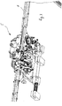
- a strapping device 1 is shown, which is provided with a control 2, a storage device 3 for storing and providing a strapping band, as well as with a strapping head 5.
- the strapping head 5 is used, among other things, to generate a feed as well as to Creation of a retraction movement of the strapping band. It is also provided with a tensioning device for applying tape tension to a tape loop, as well as a locking device for creating a lock on the strapping band.
- the strapping device has a tape guide 6 with which the tape can be placed around a packaged item 7 mechanically and automatically on a predetermined path.
- a welding and clamping unit 16 is integrated into the strapping head 5. Except for the strapping head 5, these are components of strapping devices that are known per se.
- the arranged together with the tape guide 6 on a frame 8 and in Fig. 2 Strapping head 5 shown separately has a tape drive device 15.
- Belt drive devices are basically previously known, which is why the differences to previously known belt drive devices will essentially be discussed below.
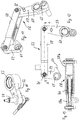
- the belt drive device according to this exemplary embodiment can, in particular, have one or more pairs of rollers 11, 12; 13 and possibly be provided with further individual pulleys. The latter, however, do not take part in the generation of the tape movement and are only provided for determining the direction of the tape run.
- the rollers 11, 12, 13 in the exemplary embodiment which generate the tape movements, at least one of the rollers 11, 12, 13 should be motor-driven to generate a tape feed or tape return movement.
- a roller 11, 12, 13 of the roller pairs formed from these rollers should preferably be driven, between which the strapping is carried out and a feed, retraction or tensioning movement and, if necessary, a chipping movement is transmitted to the tape.
- the strapping head 5 has two components, a control component 16 and a strap handling component 17.
- the control component 16 has other functions in addition to executing control functions for the components of the strapping device, for example the creation of closures between the two strap layers of a strapping as well as cutting of the strapping tape from the tape supply.
- the control component 16 is mounted on a partial carrier 18 of the strapping head, the partial carrier 18 is in turn releasably attached to a common main carrier 19 of the strapping head 5.
- the partial carrier 18 of the control component 16 can be pivoted about an axis 23.
- the elements of the strap handling component 17 are attached directly to the main beam 19 of the strapping head without their own sub-beams.
- the control component 16 is essentially provided for the execution of control and coordination functions of the functions carried out with the strapping head.
- the strap handling component 17 and the components attached to it are intended to act directly on the strapping strap.
- a tape feed device 20, a tape retraction device 21 and a tensioning device 22 are integrated into the tape handling component 17 of the strapping head 5.
- rollers 11, 12; 13 provided. Of the total of only three rollers 11, 12, 13, two rollers 11, 12 are motor-driven rollers.
- the two rollers 11, 12 are driven by the same (only one) motor 14, in the exemplary embodiment an electric motor.
- a drive train can be guided from the common motor 14 to one of the two rollers 11, 12, for example.
- the roller 11 is provided both as a drive wheel for the tape feed (tape feed wheel) and as a drive wheel for the tape retraction (tape retraction wheel).
- the roller 11 can be driven in both directions of rotation by the same drive motor 14.
- the counterclockwise direction of rotation is the tape feed direction and the clockwise direction of rotation is the tape retraction direction.
- the motor drive movement is transmitted to both wheels or rollers 11, 12 from the common motor 14 by means of a transmission device.
- the transmission device 14a comprises a toothed belt transmission which transmits the drive movement from the motor shaft to a further shaft running parallel to the motor shaft. On this further shaft, two gears are arranged, each of which belongs to a further of two sub-transmissions of the transmission device.
- the Motor drive movement is transmitted to the roller or the wheel 11 and from the other partial transmission to the tensioning wheel 12.
- both the tensioning wheel 12 and the wheel 11 rotate in different directions of rotation in the exemplary embodiment.
- the roller 11 is arranged above the roller 12.
- the roller 12 is part of the tensioning device 22 and has the function of the tensioning wheel. It has a significantly larger diameter than the roller 11.
- the tensioning wheel 12 can also be driven in both directions of rotation due to the rigid connection with the motor 14 and the drive movements carried out by the motor in both directions of rotation. However, only the drive movement in the tensioning direction is used by the tensioning wheel, ie based on the illustration of FIG Fig. 6 the direction of rotation clockwise.
- a relaxation of the strap section located in the strapping head and no longer belonging to the strap loop can take place.
- the drive movements for both the tensioning movement and the relaxation movement come from the same drive motor as for the roller 11.
- a switchable coupling can be used in the drive train not shown in detail provided, with which the drive movement can be directed either to the roller 11 or the roller 12.
- the tensioning wheel can in turn be driven in both directions of rotation, it can also be provided that the tensioning wheel can also only be driven in the direction of rotation intended for the tensioning process.
- roller 13 is adjacent to both the roller 11 and the tensioning wheel 12.
- the roller 13 is not rotationally driven and is articulated so as to be pivotable by means of a pivoting device.
- the swivel device is operatively connected to a drive, by means of which the roller can execute (motor-driven) swivel movements.
- the Counter-roller acting roller 13 can either be brought into abutment against roller 11 or in abutment against tensioning wheel 12, the strapping band being located between one of the rollers 11, 12 and the roller 13 in the respective end position of the pivotable roller 13.
- the counter-roll 13 Depending on which of the rollers 11, 12 the counter-roll 13 rests against, the counter-roll 13 then presses the belt against the corresponding roll 11, 12, so that the corresponding roll 11, 12 rotates with as little slippage as possible as a feed, retraction or tensioning movement and, if necessary, can be transferred to the strapping band as a relaxation movement.
- the counter roller 13 is thus, together with the roller 11, both a component of the tape feed device and a component of the tape retraction device. Together with the tensioning wheel 12, the counter roller 13 is also part of the tensioning device 22.
- This preferred embodiment according to the invention makes it possible to avoid the fourth roller, which was previously common in previously known solutions. In these previously known solutions, one of two counter-rollers is permanently assigned to the drive roller and the tensioning wheel. In contrast, the preferred 3-roller solution according to the invention can enable a significantly more compact design.
- the rollers 11, 12, 13 are also part of a band guide channel 28 in the strapping head 5, through which the course as well as the advance and retraction path of the band is predetermined.
- the tape guide channel 28 is in turn part of the tape guide 6.
- the strapping head 5 has a first interface 29, at which the strapping head 5 connects to the supply roll side of the tape guide.
- the one end of the tape guide channel 28 formed here is designed as a quick-change interface.
- This has a channel piece 31 which can be clamped to the strapping head by means of a pivotable clamping lever 30 and through which the tape is fed into the strapping head.
- the channel piece 31 ends immediately in front of the circumferential surface 11a of the roller 11, so that the strapping tape can be fed at least approximately tangentially to the circumferential surface 11a of the roller 11. If the roller 13 is in its end position pivoted relative to the roller 11, the tape is passed through between the rollers 11, 13, the roller 13 pressing the tape against the roller 11.
- the tape When viewed in the direction of tape advance 32, the tape proceeds to the tensioning wheel 12 as it continues.
- a circular arc-shaped channel section 28a extending over approximately 180 ° on the circumference of the tensioning wheel 12 is formed by suitable channeling means.
- the channel section 28a With regard to the strip thickness, the channel section 28a is made significantly wider than the strip thickness.
- the inner delimitation of the channel section is formed by the section of the circumferential surface 12a of the tensioning wheel 12 which is located in the region of the channel section.
- the outer boundary of the channel section 28a in the radial view has guide plates as well as an outer channel segment which can be pivoted together with the counter roller 13 and with which the outer channel section can be kept closed although the pivotable counter roller 13 is located in the area of the outer channel section. Without the pivotable channel segment 33 or another similarly acting element, at least one of the two pivot end positions of the counter roller 13 would possibly result in an open position in the channel section, which could possibly have a negative effect on reliable tape guidance.
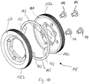
- the tensioning wheel is shown in three representations. This has a ring 37 which is provided with a recess 38 which is provided for connecting the tensioning wheel 12 to a shaft of the drive, in particular to a shaft of a transmission of the drive.
- Fig. 2 the tensioning wheel 12 mounted on the shaft is shown.
- the circular tensioning wheel is provided with a circumferential surface 12a of at least substantially constant width.
- the tensioning wheel 12 is provided on its circumferential surface 12a with knurling or toothing 39, by means of which the engagement conditions of the tensioning wheel 12 on the strapping band are improved.
- any other geometrically determined or indefinite roughening of the circumferential surface 12a of the tensioning wheel could be provided, with which a possible slip between the tensioning wheel and the strapping can be prevented at least as far as possible during the tensioning process.
- a groove 40 with a comparatively small width is introduced, which is formed significantly deeper than it is wide.
- the groove 40 are located in Embodiment two rubber-elastic O-rings 43, 44 one above the other, which are arranged radially one behind the other in the groove 40.
- one of the O-rings 43 is arranged with a smaller and the other O-rings 44 with a, in comparison, larger distance to the axis of rotation of the tensioning wheel 12.
- the width of the O-rings 43, 44 is provided in such a way that they correspond approximately to the width of the groove 40.
- the two O-rings 43, 44 are located completely within the groove 40.
- Both O-rings 43, 44 are made of rubber-elastic material.
- a ring 45 provided as a spacer element sits on the outer of the two O-rings 43, 44 and is made of a metallic material in the exemplary embodiment.
- the ring 45 is elastically deformable in this embodiment.
- the ring could be designed to be essentially rigid or dimensionally stable.
- the ring 45 could also be formed from one or more materials other than a metallic material, for example from an elastic plastic.
- this metal ring 45 is provided with a smaller width B than height H in relation to its cross section.
- the height of the O-ring is matched in relation to the groove depth and the height of the O-rings in such a way that the ring protrudes from the groove 40 with a height H 1.
- the ring 45 is thus in its in Fig. 9 shown unloaded state over the circumferential surface 12a of the clamping ring 12, in particular over its entire circumference or over the entire circumference of the clamping ring 12.
- the strapping tape is pushed from the strapping head 5 with its free tape end first through the tape guide 6, preferably at high speed.
- the counter roller 13 is in contact with one side of the belt.
- the tape is pressed with its other side against the motor-driven roller 11 by the counter roller.
- the rotary drive movement of the roller 11 in the feed direction is hereby transmitted to the strapping, which causes its feed movement in the feed direction.
- the tape comes into contact with the tensioning wheel 12 behind the run-out area of the tape from the gap between the roller 11 and the counter roller 13, but without exerting any appreciable pressure on the tensioning wheel 12.
- the end of the tape reaches the closure head again.
- the end of the tape activates a limit switch, whereby the feed movement is stopped and the end of the tape is clamped.
- the camshaft control of the control component 16 now sets the roller 11 in motion in the opposite direction of rotation to the feed direction.
- the strapping band which is still clamped between the roller 11 and the counter roller 13, is thereby moved in the opposite direction, that is to say in the band retraction direction 48.
- the circumferential length of the tape loop, the tape end of which is still clamped, is thereby continuously shortened. As a result, the tape is torn from the tape guide 6 and, as a result, applied around the respective packaged goods.
- Fig. 6 the tensioning wheel 12 is shown during the tape retraction process.
- the strap comes into contact with the tensioning wheel 12 during the tape retraction process.
- the strapping band rests on the tensioning wheel 12 for the most part over the entire arcuate channel section 28a, similar to the one that is also the case with the subsequent tensioning process.
- the tape is withdrawn here, but due to its ability to yield to this movement by moving out of the tape guide as intended, only a comparatively low tape tension is applied to the tape of the tape loop during this phase.
- the band does not lie on the circumferential surface of the tensioning wheel 12 but on the ring 45 located in the circumferential surface 12a.
- This contact with the spacer element which is embodied here as a ring 45 in the exemplary embodiment, means that the band cannot be damaged by the knurling or toothing 39 of the peripheral surface 12a during the band retraction.
- the control switches from tape retraction to generating a tape tension, whereby the tape lying against the packaged goods is to be pulled tight.
- the counter roller 13 is first pivoted from its contact position against the roller 11 into a contact position against the tensioning wheel 12.
- the tensioning wheel 12 offset in the same direction of rotation as before the roller 11, rotates at a lower speed but using a greater torque and pulls further on the strapping band.
- the belt is no longer in contact with the roller 11, which is still driven and rotating faster in the exemplary embodiment, in such a way that the roller 11 could transfer its movement to the belt.
- the tape Since the strapping tape is already in contact with the packaged goods at this stage, the tape is pulled back by the tensioning wheel 12 at most with a short length compared to the tape retraction phase. During this tensioning phase, a greater tension is primarily applied to the tape.
- the pressure of the counter roller 13 in the direction of the tensioning wheel and the belt located in between pushes the ring 45 in the direction of the groove base and thus also in the essentially radial direction in the direction of the axis of rotation of the tensioning wheel 12.
- the band rests against the ring 45 and also presses it at least in the area of the counter roller 13 in the direction of the groove base.
- the ring 45 is thus already at a smaller distance from the axis of rotation of the tensioning wheel at the beginning of the tensioning process than in its unloaded state, for example during the tape advance or retraction phase.
- the greater torque transmitted from the tensioning wheel 12 to the belt in the further course of the tensioning process compared to the belt retraction phase of the roller 11 results in a greater reaction force of the belt.
- This greater reaction force now means that the band presses the ring 45 into the groove not only in the contact area with the counter roller 13, but also over its contact length (wrap angle, seen in the circumferential direction) with the ring 45, whereby the band now along its wrap angle on the Tensioning wheel 12 rests against its peripheral surface.
- the ring 45 can protrude from the circumferential surface to a greater extent than in comparison to the unloaded state in which it protrudes a height H 1.
- each individual point of the ring is alternately pressed into the groove 40 and emerges from it again until, due to the rotation of the tensioning wheel, the Reached point at which the band wraps around a section of the circumferential surface and thereby presses the ring along this section into the groove.
- the counter roller 13 can advantageously be pressed against the roller 11 (feed roller or retraction roller) on the one hand and against the tensioning wheel 12 on the other hand with different pressure forces (when the strapping device is in use, each with a strapping band in between).
- higher pressing forces against the tensioning wheel can be advantageous for high functional reliability and the possibility of applying high band tensions to the strapping band.
- the counter roller 13 is arranged on an eccentric 50, which in turn is arranged on a shaft 51 of a carrier 52.
- the carrier has a receptacle 53 which is provided for arrangement on the bearing point 54 of the roller 11 ( Fig. 5 , 6th ).
- the receptacle 53 is freely rotatable about its axis of rotation on the bearing point 54 of the roller 11 and can thus execute pivoting movements about its axis of rotation.
- the parallelogram 56 has a long vertical lever 57, a horizontal lever 58 and a short vertical lever 59.
- the parallelogram is pivotably articulated on the long vertical lever 57 and on the short vertical lever 59.
- the levers 57 and 59 have pivot bearing points 60, 61 for this purpose.
- a rotary movement can be transmitted to the long vertical lever 57 via a bell curve 62, which movement leads to the pivoting movement of the lever 57 about its pivot bearing point 60.
- the pivoting movement of the lever 57 takes place in a clockwise direction.
- the lever 58 thereby pulls the latter towards the lever 57 at the articulation point of the short vertical lever, as a result of which the vertical lever 59 in the illustration of FIG Figures 11, 12 also pivots clockwise about its pivot bearing point 62.
- An inclined surface 64 formed on the short vertical lever 59 thereby presses on a bearing 51 arranged on the shaft 51.
- the inclined surface thereby moves in a clockwise direction (as shown in FIG Fig. 12 ) and tends to be horizontal.
- the carrier 52 executes a pivoting movement, as a result of which the counter roller 13 is pivoted from its end position against the roller 11 in the direction of the tensioning wheel 12.
- the parallelogram can be reset by a further spring 73 arranged on the pin 72 of the lever 5.
- a tensioning wheel 112 according to the invention is shown.
- the tensioning wheel 112 can be longitudinally divided with respect to its width, preferably approximately in the middle, the two parts 112b, 112c of the tensioning wheel 112 being releasably connectable to one another by means of suitable fastening elements, for example screws 114.
- a circumferential groove 140 is formed in the outer ring 137 of the tensioning wheel 112, which is open towards the circumferential surface 112a of the tensioning wheel 112 and tapers or decreases in the direction towards this.
- One or more restoring elements can be arranged in the groove 140.
- elastic ring sections 143 for example a plurality of rubber-elastic O-ring sections 143, are arranged as the restoring element. These ring sections are preferably evenly distributed in the groove 140 at a distance from one another, as is the case in the exemplary embodiment with a total of four ring sections 143.
- the restoring elements 143 are located below one or more spacer elements. In the exemplary embodiment, only a spacer element 145 designed as a closed ring is provided.
- An outer diameter of the ring 145 arranged in the groove is dimensioned in such a way that when the ring 145 is in the unloaded state, its outer circumferential surface protrudes beyond the circumferential surface 112a of the clamping ring 112. With its inner circumferential surface, the ring 145 is located in the groove.
- the restoring elements are attached to the inner circumferential surface of the circular and essentially dimensionally stable ring 145. In other embodiments, a different number of spacer elements and a different number of restoring elements can also be provided.
- the ring 145 which in the exemplary embodiment is essentially non-deformable and thus dimensionally stable due to the expected forces acting on it, is thus arranged slightly eccentrically in relation to the axis of rotation of the tensioning wheel during this process. As a result, the ring 145 protrudes further out of the groove 140 with its section not covered by the wrap angle of the strap than when the tensioning wheel is in the unloaded state of the strapping strap.
- the elastic Restoring forces from one or more of the ring cuts 143 allow the ring 145 to protrude again over its entire circumference from the groove.
- This preferred arrangement allows the ring 145 to be pressed into the groove 140 in sections during the tensioning process, during which the strapping band exerts a sufficiently high pressure force on the ring 145 located in the wrapping area of the strapping band.
- the compressive force on the section of the ring 145 currently arranged in the wrapping area of the band is not sufficiently great to push this ring section completely into the groove 140.
- the band hereby rests against the portion of the ring 145 and not against the surface of the tensioning wheel 112.
- the ring 145 holds the strap at a distance from the circumferential surface of the tensioning wheel 112.
- a further exemplary embodiment for a belt drive device 115 is shown.
- This also has only three rollers 111, 112, 113, which are responsible for applying the tape feed, tape retraction and tape tension movement to the tape through contact with the tape, the two rollers 111 and 112 by means of a motor, in particular by means of only one common motor can be driven.
- the relative arrangement of the axes of rotation of the three rollers 111, 112, 113 to one another corresponds at least approximately to the arrangement of these axes of rotation in the exemplary embodiment of FIG Fig. 5 and 6th .
- the counter roller 113 is in turn designed to be pivotable, so that it is provided in a pivot position for pressing the strapping against the roller 111 and in another pivot position for pressing the strapping against the tensioning roller 112.
- the pivoting mechanism of the counter roller 113 provided for this purpose and its drive can in principle be the same as in the exemplary embodiment of FIG Figs. 1 to 13 be trained.
- the counter roller 113 is as in the embodiment of FIG Fig. 5 and 6th rotatably mounted on an eccentric 150, so that the counter-roller 113 executes a non-circular arc-shaped movement during a pivoting movement from one of the rollers 111, 112 to the respective other roller 111, 112. As in the Fig.
- FIG. 18 and 19th is shown, on the eccentric 150 of the counter roller 113 is a Lifting device 180 supported, the lifting device 180 being supported with a carrier 181 on the frame of the strapping device 101.
- the bearing point 182 of the ventilation device on the eccentric 150 is itself arranged pivotably on the eccentric and is designed as a C-shaped or fork-shaped element 183 in order to thereby form a receptacle for one end of a piston 184.
- This piston 184 is arranged displaceably in the carrier 181 of the ventilation device 180.
- the support point is shown in Fig. 18 and 19th directly above the roller 111.
- the support 181 of the ventilation device is also pivotably mounted here.
- the ventilation device 180 is provided with a ventilation element which is provided to execute a controlled movement with which the counter roller 113 is acted upon in order to lift the counter roller 113 in its pivoted position on the roller 111 or to lift it slightly.
- the counter-roller 113 should be able to be positioned in its pivoted position on the roller 111 again after a ventilation, for example likewise by means of the ventilation device.
- the ventilation element is designed as a lifting magnet 186 which is arranged and mounted on the ventilation device 180. The lifting magnet 186 can execute a linear lifting movement with its piston 184 along the longitudinal axis 184a of its piston 184. As in Fig.
- one end of the piston 184 is arranged in the recess of the C-shaped or fork-shaped element 183, which is open towards the carrier 181.
- the end of the piston 184 and the recess of the C-shaped element can be designed in such a way that, during the ventilation movement, the end of the piston 184 in the C-shaped element can move relative to the latter.
- the elongated longitudinal axis 184a of the piston 184 runs at least approximately through the articulation point of the C-shaped element 183.
- a stroke movement of the piston 184 in the direction of the counter roller 113 thus leads to a rotary movement of the eccentric about its axis of rotation.
- the rotational movement of the eccentric 150 in turn results in the axis of rotation of the counter roller 113 being displaced in parallel and a gap or a gap between the roller 111 and the counter roller 113 increased gap results.
- the width of the gap here should have a size that is greater than the thickness of the respective strapping band being processed.
- the product GKb-32.06 from Isliker Magnete AG, CH-8450 Andelfingen, for example, can be used as a lifting magnet.
- a mechanical spring element can be arranged on the piston 184, in particular at least one compression spring 188.
- This compression spring 188 is compressed during the movement of the counter roller 113 by the tension roller 112 to rest against the roller 111 and thus tensioned in a resilient manner.
- the electrically operated magnetic reciprocating piston is switched off in this phase and therefore has no effect.
- the compression spring 188 is at least partially relaxed and the spring force supports the force exerted by the lifting magnet, with which the piston 184 is moved by the roller 111 to release the counter roller 113.
- the lifting magnet or another restoring element alone provides a force that is sufficiently high for the ventilation process.
- the tape is moved through the tape guide channel 28 in the feed direction by means of the roller 111 and the counter roller 113 resting against it and clamping the tape between the two rollers.
- the tape hits a stop or the reaching of the end of the tape guide channel can be detected in another way, for example by a light barrier.
- This generates a signal by which the control of the strapping device stops the motorized drive movement of the roller 111 and - at least essentially at the same time - triggers the stroke movement of the piston 184 of the lifting magnet.
- the stop of the drive movement of the roller 111 and the start of the ventilation process are offset in time, i.e. the stop of the drive movement occurs before or after the start of the ventilation process.
- the piston 184 extends in the direction of the C-shaped element 183 and hereby acts with its end on the C-shaped or fork-shaped element. Due to its arrangement on the eccentric 150, the eccentric is rotated during the stroke movement of the piston. In the exemplary embodiment and in the illustration of Fig. 18 the rotary movement of the eccentric takes place by an angle of rotation less than 90 ° in the counterclockwise direction. The rotary movement takes place against the spring force of the pressure spring 190, which is compressed in the process and is also articulated on the eccentric 150. As a result of the rotary movement, the counter roller 113 is lifted from the roller 111, ie raised and the distance between the two rollers 111, 113 is increased so that a gap is created between the rollers which is greater than the belt thickness.
- the strapping tape shot through the tape channel of the tape guide 6 at high speed has the tendency to form waves between the rollers 111, 112, 113 and the end of the strapping channel due to the sudden and abrupt tape stop in generic strapping devices.
- such waves can lead to malfunctions.
- the tape Due to the preferred embodiment according to the invention, in which the counter roller 113 is lifted, the tape can move back as far as necessary and freely against the feed direction in the direction of the tape supply, especially immediately after the feed has stopped, so that the tape supply for the length of the tape channel may move can move back excess and the wave formation causing tape portion in the tape guide channel.
- the control of the strapping device can then switch off the lifting magnet again.
- the solenoid loses its effect, which means that the pressure spring 190 can move the eccentric 150 back against the direction of rotation and thus bring the counter-roller 113 back into contact position against the belt, in which the belt is clamped between the roller 111 and the counter-roller 113.
- the subsequent tape retraction and tensioning process can be carried out in the same way as in the embodiments of the invention according to FIGS Figs. 1 to 13 respectively.
Landscapes
- Engineering & Computer Science (AREA)
- Mechanical Engineering (AREA)
- Theoretical Computer Science (AREA)
- Physics & Mathematics (AREA)
- General Physics & Mathematics (AREA)
- Multimedia (AREA)
- Computer Hardware Design (AREA)
- General Engineering & Computer Science (AREA)
- General Health & Medical Sciences (AREA)
- Computational Linguistics (AREA)
- Audiology, Speech & Language Pathology (AREA)
- Artificial Intelligence (AREA)
- Health & Medical Sciences (AREA)
- Computer Vision & Pattern Recognition (AREA)
- Basic Packing Technique (AREA)
- User Interface Of Digital Computer (AREA)
Description
- Die Erfindung betrifft eine Umreifungseinrichtung einer Umreifungsvorrichtung zur Umreifung von Packgut mit einem Umreifungsband, insbesondere mit einem Kunststoffumreifungsband, die mit einer Vorschub-, Rückzugs- und Spanneinrichtung versehen ist, die mit mehreren Rädern zur Übertragung einer Vorschub-, Rückzugs- und Spannbewegung auf das Umreifungsband versehen sind, wobei zumindest eines dieser Räder mit einer Antriebseinrichtung wirkverbunden oder wirkverbindbar ist, um das zumindest ein Rad der Räder für die Vorschub-, Rückzugs- und Spannbewegung in eine Rotationsbewegung um eine Rotationsachse zu versetzen.
- Derartige Umreifungsvorrichtungen, wie sie auch durch die Erfindung betroffen sind, können als stationäre Anlage ausgebildet sein, die dazu benutzt wird, größere Packgüter oder zu einer Packguteinheit zusammengestellte mehrere einzelne Packgüter mit einem oder mehreren Bandumreifungen zu versehen. Gattungsgemässe Umreifungsvorrichtungen weisen üblicherweise einen in sich geschlossenen Bandkanal auf, in dem das Band bei seiner Vorschubbewegung zur Bildung einer Bandschlaufe um das Packgut geführt ist. Innerhalb des Bandkanals kann ein sogenannter Umreifungskopf angeordnet sein, mit dem Bandbewegungs-, Bandspann- und Verschlussbildungsvorgänge am Umreifungsband ausgeführt werden. Die Bandumreifungen werden üblicherweise aus einem Band gebildet, das von einer Vorratsrolle abgezogen und als ringförmige Umreifung um das Packgut gelegt wird. Hierzu wird das Umreifungsband mit seinem freien Ende voraus in den Kanal der Umreifungsvorrichtung geschossen, der das Packgut mit Abstand portalartig oder ringförmig umgibt. Üblicherweise wird sobald das Bandende eine bestimmte Stelle im Kanal erreicht hat, das Bandende geklemmt und das Band dann wieder zurückgezogen. Als Folge davon zieht sich die Schlaufe des Umreifungsbands zu und das Band gelangt aus dem Kanal in Anlage gegen das Packgut. Anschliessend wird das Band stramm gezogen und hierbei auf das Band eine Bandspannung aufgebracht, der Bandring bzw. die Bandschlaufe mit einem Verschluss versehen und von der Vorratsrolle abgetrennt. Als Umreifungsband werden sowohl metallische Bänder als auch Kunststoffbänder eingesetzt. Die Umreifungsvorrichtungen sind üblicherweise an die mit ihnen zu verwendeten Umreifungsbandtypen angepasst, insbesondere in Bezug auf die Verbindungseinrichtung, mit der zwei abschnittsweise übereinanderliegende Bandlagen der Umreifungsbänder unlösbar miteinander verbunden werden.
- Bei vorbekannten Lösungen weist die Umreifungsvorrichtung in der Regel eine Bandvorschubeinrichtung zum Vorschub des Umreifungsbands während einer Bildung einer Bandschlaufe, eine Bandrückzugseinrichtung zum Rückzug des Umreifungsbands nach Bildung der Bandschlaufe, um das Umreifungsband an das Packgut anzulegen, sowie eine Spanneinrichtung auf, mit der bei dem am Packgut anliegenden Umreifungsband eine Bandspannung steigerbar bzw. erhöhbar ist, das Band also stramm ans Packgut angelegt wird. Diese drei Funktionskomponenten sind üblicherweise mit mehreren Rollen versehen, mittels denen während der Umreifungsbildung entsprechend den auszuführenden Funktionen Bandbewegungen auf das Umreifungsband aufbringbar sind. Üblicherweise werden zur Bewegungsaufbringung Rollenpaare eingesetzt, deren Rollen auf unterschiedlichen Seiten des Bands gegen das Band anliegen und das Band zwischen sich einklemmen. Auf diese Weise kann die motorisch erzeugte Rotationsbewegung von Rollen funktionssicher als Bandvorschub-, Bandrückzug- oder als Spannbewegung auf das Umreifungsband aufgebracht werden.
- Damit solche Umreifungsvorrichtungen innerhalb einer bestimmten Zeit eine hohe Anzahl an Umreifungsvorgängen ausführen können, sind die Bandbewegungen hochdynamisch und mit hohen Bandgeschwindigkeiten versehen. Dies gilt insbesondere für den Bandvorschub während der Bildung der Bandschlaufe, bei der das Band durch den in sich geschlossenen Bandkanal der Umreifungsvorrichtung geschossen wird. Gegen Ende der Bandschlaufenbildung wird das Band abrupt gestoppt. Dies geschieht üblicherweise dadurch, dass der Bandanfang gegen einen Stopp im Bandkanal auftrifft. Das Erreichen des Endes des Bandkanals wird üblicherweise detektiert und der Antrieb für den Bandvorschub gestoppt. Danach wird der Bandrückzug ausgeführt. Aufgrund der hohen Bewegungsenergie im Band während des Bandvorschubs, der Bandträgheit- und -steifigkeit, sowie dem abrupten Bandstopp, neigen Umreifungsbänder oftmals gegen Ende der Bandschlaufenbildung und vor der Ausführung des Bandrückzugs zu einer Wellenbildung in der Schlaufe des Umreifungsbands. Diese Wellenbildung im Band kann sich in den Bandabschnitt im Umreifungskopf hineinbewegen oder sich dort bilden, wobei ein Abweichen des Bands von seinem vorgesehen Verlauf, wie es durch eine Wellenbildung der Fall ist, zu Funktionsstörungen des Umreifungskopfs führen.
- Aus der
EP 0 095 643 A2 ist eine Vorschub- und Spanneinrichtung einer Bandumreifungsvorrichtung bekannt, die drei Rollen aufweist, mit denen die Vorschub-, Rückzugs- und Spannfunktion ausgeführt werden. Sowohl das motorisch angetriebene Spannrad als auch ein nicht angetriebenes mitlaufendes Rad sind auf einer gemeinsamen schwenkbaren Wippe angeordnet. Bei derEP 0 095 643 A2 ist vorgesehen, dass beim Vorschubvorgang und beim Rückzugsvorgang, das angetriebene Vorschubrad und ein mitlaufendes Rad das Band zwischen sich einklemmen, während das Spannrad mit Abstand zum mitlaufenden Rad angeordnet ist. Aufgrund einer steigenden Bandspannung während des Rückziehvorgangs wird das Spannrad sukzessive in Richtung auf das mitlaufende Rad geschwenkt und kommt in Anlage gegen dieses. Zu Beginn des Spannvorgangs ist somit ein Kontakt sowohl des mitlaufenden Rads mit dem schwenkbaren Spannrad als auch des mitlaufenden und ebenfalls schwenkbaren Rads mit dem Vorschieb- und Zurückziehrad gegeben. Durch den gleichzeitigen Kontakt sämtlicher drei Rollen, von denen zwei auch gleichzeitig angetrieben sind, mit dem Band, entsteht ein undefinierter Zustand. Es ist zu befürchten, dass dies die Funktionssicherheit der Vorschub- und Spanneinrichtung beeinträchtigen kann. Durch die beim Spannvorgang weiter steigende Bandspannung wird ebenfalls sukzessive und ebenfalls bandspannungsabhängig die gemeinsame Wippe des Spannrads und des mitlaufenden Rads verschwenkt, wodurch erst dann das mitlaufende Rad nicht mehr in Kontakt mit dem Vorschieb- und Zurückziehrad steht. Aus derEP 0 095 643 A2 gehen keine Maßnahmen zur Vermeidung oder zur funktionssicheren Auflösung einer sich gegen Ende des Bandvorschubvorgangs ergebenden Wellenbildung im Umreifungsband hervor. - Aus der
EP 1 177 978 A1 ist eine bandaufbringende Vorrichtung bekannt. Eine Berührungsrolle ist an dem freien Ende eines Tragarms angebracht, der sich drehen kann. Ein Umschaltmechanismus dreht den Tragarm und ändert so die Neigung des Tragarms. Die Berührungsrolle wird dabei zwischen zwei Positionen bewegt. In der ersten Position wird die Berührungsrolle auf eine Vorwärtsantriebsrolle gedrückt. In der zweiten Position wird die Berührungsrolle auf eine Rückwärtsantriebsrolle gedrückt. Die Berührungsrolle und die Rückwärtsantriebsrolle sind voneinander beabstandet. Die Berührungsrolle kann in eine dritte Position bewegt werden, wo sie sowohl von der Vorwärtsantriebsrolle als auch von der Rückwärtsantriebsrolle beabstandet bleibt. In der zweiten Position kann die Berührungsrolle mit einer kleinen Kraft oder einer großen Kraft auf die Rückwärtsantriebsrolle aufgeschoben werden. Wenn die Berührungsrolle mit geringer Kraft auf die Rückwärtsantriebsrolle gedrückt wird, zieht die Rückwärtsantriebsrolle ein Band zurück. Wenn die Berührungsrolle mit der großen Kraft auf die Rückwärtsantriebsrolle gedrückt wird, spannt die Rückwärtsantriebsrolle das Band an. - Der Erfindung liegt deshalb die Aufgabe zugrunde, bei einer gattungsgemässen Umreifungsvorrichtung zur Umreifung von Packgut mit einem Umreifungsband die Funktionssicherheit hinsichtlich einer möglichen Wellenbildung im Umreifungsband zu verbessern.
- Diese Aufgabe wird durch eine Umreifungseinrichtung der eingangs genannten Art gelöst, bei der ein betätigbares Mittel, mit dem zumindest ein Rad eines Räderpaars der Vorschubeinrichtung in einen Zustand schaltbar ist, in dem das Umreifungsband, ohne Übertragung einer entsprechenden motorischen Antriebsbewegung auf das Umreifungsband, in einer zur Bandvorschubbewegung entgegen gesetzten Richtung zwischen dem Räderpaar verschiebbar ist. Mit der Erfindung wird somit vorgesehen, den Zustand des Räderpaars von einem das Band zwischen sich klemmenden Zustand, der insbesondere den Bandvorschub ermöglicht, in einen Zustand zu verändern, in dem das Band sich unabhängig von einer angetriebenen Bewegung von einem Rad des Räderpaars, zwischen dem Räderpaar hindurchbewegen kann.
- Vorzugsweise kann vorgesehen sein, dass mit dem betätigbaren Mittel von zumindest einem der Räder des Räderpaars ein Andruck des Rads gegen das Umreifungsband reduzierbar ist, damit das Umreifungsband in einer zur Bandvorschubbewegung entgegen gesetzten Richtung zwischen dem Räderpaar verschiebbar ist. Erfindungsgemäss wird der zur Übertragung einer motorischen Antriebsbewegung über eines der beiden Räder auf das Umreifungsband vorgesehene Klemmzustand zwischen dem Räderpaar zumindest insoweit reduziert, das zwischen dem Band und dem Räderpaar sich Schlupf oder ein vergrösserter Spalt einstellen kann. Sofern bei einer Aufhebung der Klemmwirkung ein vergrösserter Spalt zwischen den Umfangsflächen der Räder erzeugt wird, sollte dieser Spalt vorzugsweise grösser als die Banddicke sein. Die Klemmwirkung kann beispielsweise bereits dadurch reduziert werden, dass eine Druckkraft, mit der die beiden Räder gegeneinander gedrückt werden, reduziert wird, beispielsweise durch eine veränderbar einstellbare Grösse dieser Druckkraft. Eine solche Reduzierung der Klemmwirkung kann bereits ausreichend sein, damit sich ein Umreifungsband von sich aus zwischen dem Räderpaar bewegen kann.
- Eine Möglichkeit zur Bewegung des Umreifungsbands zwischen den Rädern des Räderpaars kann aber alternativ auch dadurch erreicht werden, dass eine Wirkverbindung zwischen einem angetriebenen Rad und seinem Antrieb aufgehoben wird, so dass beide Räder des Räderpaars frei und ohne Haltemoment der Antriebseinrichtung drehbar sind. Eine solche Aufhebung einer Wirkverbindung kann beispielsweise mittels einer schaltbaren Kupplung im Antriebsstrang des angetriebenen Rads vorgenommen werden. Mit dieser schaltbaren Kupplung kann vorzugsweise auch die Wirkverbindung wieder hergestellt werden, um nachfolgend wieder eine Antriebsbewegung von der angetriebenen Rolle auf das Umreifungsband aufzubringen, insbesondere eine Bandrückzugsbewegung.
- Durch eine freie Drehbarkeit des Räderpaars, oder zumindest Schlupf oder vorzugsweise einem ausreichend großen Spalt zwischen den Rädern, wird es dem Umreifungsband ermöglicht, überschüssige Bandlänge der Bandschlaufe unmittelbar nach oder bereits während der Entstehung der Bandschlaufe wieder zwischen dem Räderpaar hindurch abzubauen, wodurch eine Wellenbildung möglichst vermieden werden soll. Eine beginnende überschüssige Bandlänge im Umreifungskanal führt zu Stauchungen in der Bandschlaufe und damit zu Druck- und/oder Biegespannungen im Umreifungsband. Übliche Umreifungsbänder weisen eine Biegesteifigkeit auf, die solchen Bändern die Tendenz verleihen, Druck- und Biegespannungen dadurch abzubauen, dass sie sich in eine Möglichkeit ebene und geradlinig verlaufende Ausrichtung begeben. Dies wird durch die Erfindung in vorteilhafter Weise dadurch genutzt, dass durch die Schaffung einer Bewegungsmöglichkeit des Bandes zwischen dem Räderpaar hindurch, aufgrund der Bandselbstentspannung überschüssige Bandlänge sich insbesondere von alleine zwischen den Rädern wieder aus dem Bandkanal herausbewegen kann.
- In einer günstigen Ausführungsform der Erfindung ist ein Rad, dessen Umfangsfläche zum Kontakt mit dem Umreifungsband vorgesehen ist, sowohl Bestandteil der Spann-, als auch der Bandvorschub- als auch der Bandrückzugseinrichtung. Ferner ist es besonders zweckmässig, dass die Rolle zur Ausführung von Überführungsbewegungen von einer ihrer Anlagepositionen in die jeweils andere Anlageposition eine angetriebene Schwenkbewegung ausführt.
- In einer bevorzugten Ausführungsform der Erfindung kann das betätigbare Mittel eine Lüfteinrichtung umfassen, mittels welcher zwei als Räderpaar angeordnete Räder - insbesondere Räder der Bandvorschub- und/oder der Bandrückzugseinrichtung - zwischen denen das Umreifungsband zu einer Bewegungsübertragung klemmbar ist und von denen ein Rad motorisch rotativ um seine Drehachse antreibbar ist, in einem Abstand zueinander anordenbar sind, der insbesondere eine freie, d.h. nicht motorisch angetriebene, Bewegung des Umreifungsbands zwischen den beiden Rädern hindurch ermöglicht. Eine bevorzugte Ausführungsform der Erfindung kann somit eine Lüfteinrichtung umfassen, mit welcher zwischen einer als Gegenrolle vorgesehenen Rolle and einer zur Aufbringung einer Bandbewegung vorgesehenen motorisch angetriebenen Rolle ein im Vergleich zur Aufbringung von Bandbewegungen vergrösserter Abstand erzeugbar ist. Vorzugsweise können mittels der Lüfteinrichtung die beiden Räder in einem Abstand anordenbar sein, der größer ist als die Dicke des jeweils zwischen dem Räderpaar angeordneten Umreifungsbands.
- In einer weiteren bevorzugten Ausfahrungsform der Erfindung können Mittel zur Zurückstellung von einem der beiden Räder zu einem Abstand der beiden Räder zueinander vorgesehen sein, durch den beide Räder gegen unterschiedliche Seiten des Umreifungsbands anliegen.
- Mit der Erfindung ist es somit möglich und vorgesehen, den Abstand zwischen einem insbesondere zum Bandvorschub vorgesehenen Rollen- oder Räderpaar von einem zunächst geringeren Abstand zu vergrössern, um hierdurch einen Durchlass zwischen den Rädern zu schaffen, damit sich das Umreifungsband zwischen den beiden Räder entgegen der Bandvorschubrichtung bei der Bandschlaufenbildung, hindurch- und zurückbewegen kann. Hierdurch ist es ferner möglich, dass sich, in Bezug auf die Länge des Bandkanals der Umreifungsvorrichtung, überschüssige Bandlänge, die zu einer Wellenbildung führen kann, von alleine und entgegen der Bandvorschubrichtung, in Richtung auf den Bandvorrat zurückbewegen kann. Das auf das Räderpaar einwirkende betätigbare Mittel, vorzugsweise eine Lüfteinrichtung oder eine Kupplung, kann somit mit Vorteil vor allem dazu vorgesehen sein, zumindest im Wesentlichen nach der Erzeugung einer Bandschlaufe durch die Umreifungseinrichtung und zumindest im Wesentlichen vor der Ausführung des Bandrückzugs zum Anlegen der Bandschlaufe eine Wellenbildung zu vermeiden oder eine bereits sich bildende Wellenbildung im Umreifungsband wieder aufzulösen.
- Ausgangspunkt für den Einsatz der Lüfteinrichtung ist vorzugsweise eine Anordnung der Rollen bzw. Räder des Räderpaars in einer Position, in der diese gegeneinander anliegen und hierbei das Band zwischen sich mit Druck gegen das Band aufnehmen. Die beiden Rollen oder Räder klemmen somit das Band zwischen sich ein, wodurch eine Rotationsbewegung von einer der beiden Räder zu einer Veschiebebewegung des Bands führt. Das in der Regel aufgrund der Bandbewegung passiv mitdrehende zweite Rad hat hierbei die Funktion einer nicht motorisch angetriebenen Gegenrolle, mit der das Band gegen das angetriebene Rad angedrückt und somit das Band zwischen den beiden Rädern eingeklemmt wird. Eine Bewegung des Bands ist deshalb nur dann möglich, wenn das angetriebene Rad eine Rotationsbewegung ausführt. Zur Erzeugung der Andruckkraft der Gegenrolle gegen das angetriebene Rad, ist die Gegenrolle üblicherweise durch ein entsprechendes Element kraftbelastet, beispielsweise durch ein Federelement, oder einen Pneumatikzylinder oder ein anderes geeignetes, eine Kraft ausübendes Element. In diesem Zustand beträgt der Spalt zwischen den beiden Rädern somit in etwa der Banddicke des jeweils zu verarbeitenden Umreifungsbands. Ein solches Räderpaar kann vorzugsweise zur Erzeugung der Bandvorschubbewegung vorgesehen sein. Das gleiche oder ein anderes Räderpaar kann auch zur Erzeugung der Bandrückzugsbewegung genutzt werden, bei der die zuvor erzeugte Bandschlaufe an das Packgut in Anlage gebracht wird. Werden für den Bandvorschub- und den Bandrückzugsvorgang zwei unterschiedliche Räderpaare vorgesehen, so kann für jedes dieser Räderpaare eine Lüfteinrichtung vorhanden sein.
- Die Lüfteinrichtung kann mit zumindest einem Lüftelement versehen sein, das auf zumindest eines der beiden Räder unmittelbar oder indirekt derart einwirkt, dass sich der Abstand zwischen den beiden Rädern vergrössert. Der sich temporär durch Betätigung der Lüfteinrichtung einstellende Abstand des Umfangs der beiden Räder sollte deutlich grösser sein als die Banddicke. Vorzugsweise kann dieser Abstand und damit der sich zwischen den beiden Rädern ergebende Spalt einen Betrag aufweisen der aus einem Bereich vom ca. 1,5-fachen bis 10-fachen der Banddicke, vorzugsweise aus einem Bereich vom 2-fachen bis 8-fachen der Banddicke und besonders bevorzugt aus einem Bereich vom 3-fachen bis 7-fachen der Banddicke gewählt ist. Mit einem Spalt zwischen den beiden zusammenwirkenden Rädern in einer Grösse aus den vorstehend genannten Bereichen, kann dem Band ermöglicht werden, sich in Richtung des Bandvorrats und damit zwischen dem Räderpaar hindurch zu entspannen. Der überschüssige Bandanteil im Bandkanal führt zu den zu vermeidenden Wellenbildungen oder anderen Bandstauchungen, die wiederum zu einer zur Reduzierung der Bandlänge im Bandkanal genutzten Druck- und Biegespannung im Band der Bandschlaufe führen kann.
- Der Lüftvorgang mittels der Lüfteinrichtung - oder ein Schaltvorgang des betätigbaren Mittels für eine auf sonstige Weise geschaffene Bewegungsmöglichkeit des Bands zwischen dem Räderpaar und entgegengesetzt zur Bandvorschubsrichtung - kann vorzugsweise zumindest in etwa zu einem Zeitpunkt einsetzen, zu dem der Bandvorschubvorgang gestoppt wird. Er kann jedoch auch zu einem Zeitpunkt einsetzen, zu dem der Bandvorschub noch ausgeführt wird oder nachdem er bereits beendet ist. Der Beginn des Lüftvorgangs oder der Rückbewegungsmöglichkeit für das Band erfolgt vorzugsweise zu einem vorbestimmten bzw. zu einem veränderbaren vorbestimmbaren Zeitpunkt in Bezug auf eine bestimmte Position des durch den Bandkanals geschobenen freien Bandanfangs. Die Bandumreifungsvorrichtung kann vorzugsweise Detektionsmittel aufweisen, mit denen das Erreichen einer bestimmten Position des Bandanfangs bei seiner Bewegung durch den Bandkanal detektiert wird. Auf Basis dieser Detektion kann das Detektionsmittel ein Signal generieren, das der Steuerung der Umreifungseinrichtung zugeführt wird. Die Steuerung kann als Reaktion auf dieses Signal die Bandvorschubeinrichtung stoppen, insbesondere den Antriebsmotor stoppen, der den Bandvorschub auf das Band überträgt. Ebenfalls als Reaktion auf das Signal des Detektionsmittels kann die Steuerung auch das betätigbare Mittel, insbesondere die Lüfteinrichtung einschalten, wodurch der vorgesehene Abstand und Spalt zwischen den Umfangsflächen der Räder des Räderpaars erzeugt wird, welches das Antriebsrad für den Bandvorschub beinhaltet. Der Lüftvorgang kann hierdurch auf einen optimalen Zeitpunkt gelegt werden, zu dem einerseits die Funktionssicherheit des Umreifungsvorgangs verbessert und andererseits die Zeit für einen Umreifungsvorgang aufgrund des Lüftvorgangs möglichst nicht oder höchstens nur gering verlängert wird.
- Das betätigbare Mittel, insbesondere die Lüfteinrichtung, kann vorzugsweise mit einem Mittel zur Rückstellung der beiden Räder des jeweiligen Räderpaars in eine Position versehen sein, in welcher die beiden Räder gegen unterschiedliche Seiten des Umreifungsbands anliegen und das Umreifungsband somit bei einer Antriebsbewegung des angetriebenen Rads möglichst schlupffrei zwischen sich aufnehmen und antreiben kann. Das Mittel zur Rückstellung kann beispielsweise das Andruckelement sein, mittels dem die beiden Räder des Räderpaars mit einer Andruckkraft gegeneinander in Anlage gebracht werden. Mit einer solchen Ausführungsform kann ein zusätzliches Bauelement für die Funktion der Rückstellung des Gegenrads in seine Andruckposition, vermieden werden. In einer weiteren geeigneten Ausführungsform kann dieses Andruckelement ein auf die Gegenrolle wirkende Druckfeder sein. Mit Vorteil kann der Lüftvorgang - oder die auf andere Weise geschaffene Bewegungsmöglichkeit des Bands - zwischen den beiden Rollen bzw. Rädern vor der Ausführung des mit motorischer Antriebsbewegung bewirkten Bandrückzugsvorgang somit wieder aufgehoben und die beiden Rollen wieder gegeneinander - bzw. gegen das Band - in Anlage gebracht werden. Die Rückbewegungsmöglichkeit des Bands aufgrund des Schaltvorgangs - insbesondere der Lüftvorgang - erfolgt somit vorzugsweise zeitlich zwischen dem Bandvorschub- und dem Bandrückzugsvorgang. Eine zeitliche Überschneidung zwischen dem Bandvorschub- und/oder dem Bandrückzugsvorgang einerseits sowie dem Lüftvorgang andererseits ist hierbei möglich, aber nicht zwingend erforderlich.
- In einer weiteren günstigen Ausgestaltung der Erfindung, kann die nicht motorisch angetriebene Gegenrolle auf einem drehbaren Exzenter angeordnet sein. Die Lüfteinrichtung kann hier auf den Exzenter einwirken, um durch Drehung des Exzenters und der Exzentrizität einen Spalt zwischen den beiden Rollen zu erzeugen, der grösser ist als die Banddicke. In einer vorteilhaften Weiterbildung der Erfindung, kann nach Abschluss des Lüftvorgangs der Exzenter wieder in dann entgegen gesetzte Richtung zurückgedreht werden, wodurch die beiden Rollen wieder das Band zwischen sich einklemmen und mit den beiden Rollen nun ein Bandrückzugsvorgang erfolgen kann. Diese bevorzugte Ausführungsform der Erfindung hat unter anderem den Vorteil, dass mittels eines Exzenters mit vergleichsweise geringem erforderlichem Bauraum, eine schnelle Bewegung der Gegenrolle zur Erzeugung eines Abstands zur angetriebenen Rolle sowie wieder eine Zustellung zur angetriebenen Rolle möglich ist. In anderen Ausführungsformen der Erfindung kann der Abstand zwischen den beiden Rollen für den Lüftvorgang selbstverständlich auch auf andere Weise erfolgen, beispielsweise durch eine Schwenkbewegung oder eine lineare Bewegung von zumindest einer der beiden Rollen.
- In einer weiteren zweckmässigen Ausgestaltung der Erfindung kann vorgesehen sein, dass die Lüftbewegung durch ein linear bewegbares angetriebenes Element, wie beispielweise ein Hubkolben, erfolgt. Derartige Hubelemente, sind in vielfacher Weise und mit unterschiedlichen Antriebsprinzipien verfügbar. Mit solchen Hubelementen lässt sich deshalb die erforderliche Antriebsbewegung für die Lüfteinrichtung besonders funktionssicher erzeugen. Zudem ist es mit solchen Antriebselementen auch mit vergleichsweise geringem Aufwand möglich, bereits bestehende Umreifungsvorrichtungen mit einer Lüfteinrichtung nachzurüsten.
- Schliesslich kann in einer weiteren bevorzugten Ausführungsform der Erfindung zum Kontakt mit dem Umreifungsband bei der Ausführung und Aufbringung der Vorschub-, Rückzugs- und Spannbewegung auf das Band insgesamt höchstens drei Rollen am Umreifungskopf vorgesehen sind, die im Zusammenhang mit diesen Funktionen mit dem Umreifungsband in Kontakt kommen, und die höchstens drei Rollen hierbei in unterschiedlichen Kombinationen miteinander jeweils paarweise auf beiden Seiten des Umreifungsbands in Anlage gegen das Umreifungsband bringbar sind.
- Weitere bevorzugte Ausgestaltungen der Erfindung ergeben sich aus den Ansprüchen, der Beschreibung und der Zeichnung. Der Offenbarungsgehalt der Patentansprüche wird hiermit durch Bezugnahme in die Beschreibung mit aufgenommen. Die Erfindung wird anhand von in den Figuren rein schematisch dargestellten Ausführungsbeispielen nachfolgend näher erläutert, es zeigen:
- Fig. 1
- eine stark schematisierte Darstellung einer erfindungsgemässen Umreifungsvorrichtung, die mit einem erfindungsgemässen Umreifungskopf versehen ist;
- Fig. 2
- eine perspektivische Darstellung eines erfindungsgemässen Umreifungskopfs;
- Fig. 3
- eine perspektivische Darstellung von oben des in eine Bandführung einer Umreifungsvorrichtung integrierten Umreifungskopfs aus
Fig. 2 ; - Fig. 4
- eine Seitenansicht auf den Umreifungskopf aus
Fig. 2 , bei dem sich eine Komponente in einer ausgeschwenkten Serviceposition befindet; - Fig. 5
- eine perspektivische Teildarstellung des Umreifungskopfs aus
Fig. 2 , mit einer Darstellung der Bandantriebseinrichtung; - Fig. 6
- eine Vorderansicht auf die Bandantriebseinrichtung aus
Fig. 5 ; - Fig. 7
- eine perspektivische Darstellung eines erfindungsgemässen Spannrads mit einer Teildarstellung der Rändelung der Umfangsfläche des Spannrads;
- Fig. 8
- eine Vorderansicht auf das Spannrad aus
Fig. 7 ; - Fig. 9
- eine Querschnittsdarstellung des Spannrads entlang einer Durchmesserlinie;
- Fig. 10
- eine Komponente eines Hebelgetriebes für eine Gegenrolle der Bandantriebseinrichtung;
- Fig. 11
- eine weitere Komponente des Hebelgetriebes der Gegenrolle in einer perspektivischen Darstellung;
- Fig. 12
- die Komponente aus
Fig. 11 in einer Vorderansicht; - Fig. 13
- eine Schnittdarstellung der Komponente aus
Fig. 11 und 12 ; - Fig. 14
- eine explosionsartige Darstellung eines weiteren bevorzugten Ausführungsbeispiels eines Spannrads;
- Fig. 15
- eine perspektivische Darstellung des Spannrads aus
Fig. 14 ; - Fg. 16
- eine Vorderansicht des Spannrads aus
Fig. 14 und15 ; - Fig. 17
- eine Schnittdarstellung des Spannrads aus
Fig. 14-16 ; - Fig. 18
- ein weiteres Ausführungsbeispiel für eine erfindungsgemässe Bandantriebseinrichtung mit einer Lüfteinrichtung in einer Teildarstellung eines Umreifungskopfs;
- Fig. 19
- die Bandantriebseinrichtung aus
Fig. 18 in einer Darstellung, in der eine Gegenrolle von der mit ihr zusammenwirkenden angetriebenen Rolle gefüftet ist. - In
Fig. 1 ist eine Umreifungsvorrichtung 1 gezeigt, die mit einer Steuerung 2, einer Vorratseinrichtung 3 zur Bevorratung und zum Verfügungsstellen eines Umreifungsbandes, sowie mit einem Umreifungskopf 5 versehen ist. Der Umreifungskopf 5 dient unter anderem zur Erzeugung einer Vorschub- sowie zur Erzeugung einer Rückzugsbewegung des Umreifungsbandes. Er ist ausserdem mit einer Spanneinrichtung, zur Aufbringung einer Bandspannung auf eine Bandschlaufe, sowie eine Verschlusseinrichtung zur Erzeugung eines Verschlusses am Umreifungsband, versehen. Zudem weist die Umreifungsvorrichtung eine Bandführung 6 auf, mit der das Band maschinell und automatisch auf einem vorgegebenen Weg um ein Packgut 7 gelegt werden kann. In den Umreifungskopf 5 ist zudem eine Schweiss- und Klemmeinheit 16 integriert. Bis auf den Umreifungskopf 5 handelt es sich hierbei um an sich bekannte Komponenten von Umreifungsvorrichtungen. - Der zusammen mit der Bandführung 6 auf einem Gestell 8 angeordnete und in
Fig. 2 separat dargestellte Umreifungskopf 5 weist eine Bandantriebseinrichtung 15 auf. Bandantriebseinrichtungen sind grundsätzlich vorbekannt, weshalb nachfolgend im wesentlichen auf die Unterschiede zu vorbekannten Bandantriebseinrichtungen eingegangen wird. Die Bandantriebseinrichtung gemäss dieses Ausführungsbeispiels kann insbesondere mit einem oder mit mehreren Rollenpaaren 11, 12; 13 sowie eventuell mit weiteren einzelnen Umlenkrollen versehen sein. Letztere nehmen jedoch an der Erzeugung der Bandbewegung nicht teil und sind nur für die Bestimmung der Bandverlaufsrichtung vorgesehen. Von den im Ausführungsbeispiel drei Rollen 11, 12, 13, welche die Bandbewegungen erzeugen, sollte zumindest eine der Rollen 11, 12, 13 zur Erzeugung einer Bandvorschub- bzw. Bandrückschubbewegung motorisch angetrieben sein. Es sollte dabei vorzugsweise jeweils eine Rolle 11, 12, 13 der aus diesen Rollen gebildeten Rollenpaaren angetrieben sein, zwischen denen das Umreifungsband durchgeführt und dabei eine Vorschub-, Rückzugs- oder Spannbewegung sowie gegebenenfalls eine Entspananbewegung auf das Band übertragen wird. - Der Umreifungskopf 5 weist zwei Komponenten auf, eine Steuerungskomponente 16 und eine Bandhandhabungskomponente 17. Im Ausführungsbeispiel hat die Steuerungskomponente 16 ausser der Ausführung von Steuerungsfunktionen für die Komponenten der Umreifungseinrichtung noch weitere Funktionen, beispielsweise die Erzeugung von Verschlüssen zwischen den zwei Bandlagen einer Umreifung sowie das Abtrennen des Umreifungsbands vom Bandvorrat. Die Steuerungskomponente 16 ist dabei auf einem Teilträger 18 des Umreifungskopfs montiert, wobei der Teilträger 18 wiederum an einem gemeinsamen Hauptträger 19 des Umreifungskopfs 5 lösbar befestigt ist. Wie insbesondere aus
Fig. 4 hervorgeht, ist der Teilträger 18 der Steuerungskomponente 16 um eine Achse 23 schwenkbar. Die Elemente der Bandhandhabungskomponente 17 sind ohne eigenen Teilträger direkt am Hauptträger 19 des Umreifungskopfs befestigt. Im Ausführungsbeispiel ist die Steuerungskomponente 16 im wesentlichen zur Ausführung von Steuerungs- und Koordinierungsfunktionen der mit dem Umreifungskopf ausgeführten Funktionen vorgesehen. Die Bandhandhabungskomponente 17 und die an ihr angebrachten Komponenten sind hingegen zur unmittelbaren Einwirkung auf das Umreifungsband vorgesehen. - In die Bandhandhabungskomponente 17 des Umreifungskopfs 5 ist eine Bandvorschubeinrichtung 20, eine Bandrückzugseinrichtung 21 sowie eine Spanneinrichtung 22 integriert. Gemäss des hier gezeigten Ausführungsbeispiels sind für die Bandvorschub-, Bandrückzugs- und die Spanneinrichtung 20, 21, 22 gemeinsame Rollen 11, 12; 13 vorgesehen. Von den insgesamt nur drei Rollen 11, 12, 13 sind zwei Rollen 11, 12 motorisch angetriebene Rollen. Die beiden Rollen 11, 12 werden mit dem gleichen (nur einen) Motor 14, im Ausführungsbeispiel einem Elektromotor, angetrieben. Hierzu kann beispielsweise von dem gemeinsamen Motor 14 jeweils ein Antriebsstrang zu einer der beiden Rollen 11, 12 geführt sein. Die Rolle 11 ist hierbei sowohl als Antriebsrad für den Bandvorschub (Bandvorschubsrad) als auch als Antriebsrad für den Bandrückzug (Bandrückzugsrad) vorgesehen. Um im dargestellten Ausführungsbeispiel diese beiden Funktionen mit nur einem Rad ausführen zu können, ist die Rolle 11 mit dem gleichen Antriebsmotor 14 in beide Drehrichtungen antreibbar. In der Darstellung von
Fig. 6 ist dabei die Drehrichtung entgegen des Uhrzeigersinns die Bandvorschubrichtung und die Drehrichtung im Uhrzeigersinn die Bandrückzugrichtung. Wie inFig. 2 gezeigt ist, wird vom gemeinsamen Motor 14 mittels einer Getriebeeinrichtung die motorische Antriebsbewegung auf beide Räder bzw. Rollen 11, 12 übertragen. Im vorliegenden Ausführungsbeispiel umfasst die Getriebeeinrichtung 14a ein Zahnriemengetriebe, das die Antriebsbewegung von der Motorwelle auf eine zur Motorwelle parallel verlaufende weitere Welle überträgt. Auf dieser weiteren Welle sind zwei Zahnräder angeordnet, die je zu einem weiteren von zwei Teilgetrieben der Getriebeeinrichtung gehören. Von einem dieser beiden Teilgetrieben der Getriebeeinrichtung wird die motorische Antriebsbewegung auf die Rolle bzw. das Rad 11 und vom anderen Teilgetriebe auf das Spannrad 12 übertragen. Je nach Drehrichtung der Motorwelle drehen somit im Ausführungsbeispiel sowohl das Spannrad 12 als auch das Rad 11 in unterschiedliche Drehrichtungen. - In der in
Fig. 5 ,6 wiedergegebenen Einbaulage des Umreifungskopfs ist die Rolle 11 oberhalb der Rolle 12 angeordnet. Die Rolle 12 ist Bestandteil der Spanneinrichtung 22 und hat die Funktion des Spannrads. Sie weist einen deutlich größeren Durchmesser als die Rolle 11 auf. Das Spannrad 12 ist aufgrund der starren Verbindung mit dem Motor 14 und der vom Motor ausgeführten Antriebsbewegungen in beiden Drehrichtungen, ebenfalls in beide Drehrichtungen antreibbar. Für die Aufbringung der vorgesehenen Bandspannung auf das Umreifungsband, insbesondere auf die Bandschlaufe, wird vom Spannrad jedoch nur die Antriebsbewegung in Spannrichtung genutzt, d.h. bezogen auf die Darstellung vonFig. 6 die Drehrichtung im Uhrzeigerrichtung. In bevorzugten Ausführungsformen kann durch eine dem Spannvorgang nachfolgende und zur Drehrichtung beim Spannvorgang entgegengesetzte Rotationsbewegung des Spannrads eine Entspannung des sich im Umreifungskopf befindlichen und nicht mehr zur Bandschlaufe gehörenden Bandabschnitts stattfinden. Die Antriebsbewegungen sowohl für die Spannbewegung als auch für die Entspannbewegung stammen vom gleichen Antriebsmotor wie für die Rolle 11. Als Alternative zum hier dargestellten Ausführungsbeispiel der Erfindung kann in anderen Ausführungsformen im nicht näher dargestellten Antriebsstrang vom Motor zu den beiden Rollen 11, 12 eine schaltbare Kupplung vorgesehen, mit der die Antriebsbewegung entweder auf die Rolle 11 oder die Rolle 12 geleitet werden kann. Neben Ausführungsformen in denen das Spannrad wiederum in beide Drehrichtungen antreibbar ist, kann auch vorgesehen sein, dass das Spannrad auch nur in die die für den Spannvorgang vorgesehene Drehrichtung antreibbar ist. - Wie der Darstellung von
Fig. 6 zu entnehmen ist, ist die Rolle 13 sowohl zur Rolle 11 als auch zum Spannrad 12 benachbart. Die Rolle 13 ist rotativ nicht angetrieben und mittels einer Schwenkeinrichtung schwenkbar angelenkt. Die Schwenkeinrichtung ist mit einem Antrieb wirkverbunden, durch welche die Rolle (motorisch) angetriebene Schwenkbewegungen ausführen kann. Durch die Schwenkbewegung kann die als Gegenrolle fungierende Rolle 13 entweder in Anlage gegen die Rolle 11 oder in Anlage gegen das Spannrad 12 gebracht werden, wobei sich in der jeweiligen Endlage der schwenkbaren Rolle 13 jeweils das Umreifungsband zwischen einer der Rollen 11, 12 und der Rolle 13 befindet. Je nachdem, gegen welche der Rollen 11, 12 die Gegenrolle 13 anliegt, drückt die Gegenrolle 13 das Band dann an die entsprechende Rolle 11, 12, so dass die entsprechende Rolle 11, 12 ihre Rotationsbewegung möglichst schlupffrei als Vorschub-, Rückzug- oder Spannbewegung sowie gegebenenfalls als Entspannbewegung auf das Umreifungsband übertragen kann. Die Gegenrolle 13 ist somit zusammen mit der Rolle 11 sowohl Bestandteil der Bandvorschub- als auch Bestandteil der Bandrückzugseinrichtung. Zusammen mit dem Spannrad 12 ist die Gegenrolle 13 auch Bestandteil der Spanneinrichtung 22. Durch diese bevorzugte erfindungsgemässe Ausgestaltung kann die bisher bei vorbekannten Lösungen übliche vierte Rolle vermieden werden. Bei diesen vorbekannten Lösungen sind der Antriebsrolle und dem Spannrad jeweils eine von zwei Gegenrollen fest zugeordnet. Die bevorzugte erfindungsgemässe 3-Rollen Lösung kann demgegenüber eine deutlich kompaktere Ausgestaltung ermöglichen. - Die Rollen 11, 12, 13 sind im Umreifungskopf 5 zudem Bestandteil eines Bandführungskanals 28, durch den der Verlauf sowie der Vor- und Rückzugsweg des Bands vorbestimmt wird. Der Bandführungskanal 28 ist wiederum Teil der Bandführung 6. Wie in
Fig.6 zu erkennen ist, weist der Umreifungskopf 5 eine erste Schnittstelle 29 auf, an der sich der Umreifungskopf 5 an die Vorratsrollenseite der Bandführung anschliesst. Das hier ausgebildete eine Ende des Bandführungskanals 28 ist als Schnellwechselschnittstelle ausgebildet. Diese weist ein mittels eines schwenkbaren Klemmhebels 30 an den Umreifungskopf klemmbares Kanalstück 31 auf, durch den das Band in den Umreifungskopf zugeführt wird. Das Kanalstück 31 endet unmittelbar vor der Umfangsfläche 11a der Rolle 11, so dass das Umreifungsband zumindest näherungsweise tangential zur Umfangsfläche 11a der Rolle 11 zugeführt werden kann. Befindet sich die die Rolle 13 in ihrer zur Rolle 11 geschwenkten Endposition, so wird das Band zwischen den Rollen 11, 13 hindurchgeführt, wobei die Rolle 13 das Band gegen die Rolle 11 drückt. - In Bandvorschubrichtung 32 gesehen, gelangt das Band im seinem weiteren Verlauf zum Spannrad 12. Hier ist von der Gegenrolle 13 ausgehend, durch geeignete Kanalbildungsmittel ein sich über ungefähr 180° am Umfang des Spannrads 12 erstreckender kreisbogenförmigen Kanalabschnitt 28a gebildet. In Bezug auf die Banddicke ist der Kanalabschnitt 28a deutlich breiter ausgebildet als die Banddicke. Die innere Begrenzung des Kanalabschnitts wird durch den sich jeweils im Bereich des Kanalabschnitts befindenden Abschnitt der Umfangsfläche 12a des Spannrads 12 gebildet. Die in radialer Sicht äussere Begrenzung des Kanalabschnitts 28a weist Führungsbleche sowie ein zusammen mit der Gegenrolle 13 schwenkbares äusseres Kanalsegment auf, mit dem sich der äussere Kanalabschnitt geschlossen halten lässt, obwohl sich die schwenkbare Gegenrolle 13 im Bereich des äusseren Kanalabschnitts befindet. Ohne das schwenkbare Kanalsegment 33 oder eines gleichwirkenden anderen Elements würde sich zumindest in einer der beiden Schwenkendpositionen der Gegenrolle 13 eventuell eine offene Stelle des Kanalabschnitts ergeben, die sich in Bezug auf eine sichere Bandführung möglicherweise negativ auswirken könnte.
- In den
Fig. 7, 8, 9 ist das Spannrad in drei Darstellungen gezeigt. Dieses weist einen Ring 37 auf, der mit einer Ausnehmung 38 versehen ist, die zur Verbindung des Spannrads 12 mit einer Welle des Antriebs, insbesondere mit einer Welle eines Getriebes des Antriebs vorgesehen ist. InFig. 2 ist das auf die Welle montierte Spannrad 12 gezeigt. Wie ebenfalls ausFig. 6 hervorgeht, ist das kreisförmige Spannrad mit einer Umfangsfläche 12a mit zumindest im wesentlichen konstanter Breite versehen. Das Spannrad 12 ist an seiner Umfangsfläche 12a mit einer Rändelung oder Verzahnung 39 versehen, durch welche die Eingriffsverhältnisse des Spannrads 12 am Umreifungsband verbessert werden. Anstelle einer Rändelung oder Verzahnung 39 könnte auch jede andere geometrisch bestimmte oder unbestimmte Aufrauhung der Umfangsfläche 12a des Spannrads vorgesehen sein, mit der ein beim Spannvorgang möglicher Schlupf zwischen dem Spannrad und dem Umreifungsband zumindest weitestgehend verhindert werden kann. - Vorzugsweise zumindest in etwa mittig - in Bezug auf die Breite des Spannrads 12 - ist mit Abstand zu den seitlichen Rändern des Spannrads über den gesamten Umfang der Umfangsfläche 12a eine Nut 40 mit einer vergleichsweise geringen Breite eingebracht, die deutlich tiefer als breit ausgebildet ist. In der Nut 40 befinden sich im Ausführungsbeispiel zwei gummielastische O-Ringe 43, 44 übereinander, die in der Nut 40 radial hintereinander angeordnet sind. Hierbei ist einer der O-Ringe 43 mit einer geringeren und der andere O-Ringe 44 mit einem im Vergleich dazu grösseren Abstand zur Drehachse des Spannrads 12 angeordnet. Die Breite der O-Ringe 43, 44 ist dabei derart vorgesehen, dass sie in etwa der Breite der Nut 40 entsprechen. Die beiden O-Ringe 43, 44 befinden sich vollständig innerhalb der Nut 40. Beide O-Ringe 43, 44 sind aus gummielastischem Material gebildet.
- Auf dem äusseren der beiden O-Ringe 43, 44 sitzt ein als Abstandselement vorgesehener Ring 45 auf, der im Ausführungsbeispiel aus einem metallischen Werkstoff gestaltet ist. Der Ring 45 ist in diesem Ausführungsbeispiel elastisch verformbar. Ebenso könnte der Ring im wesentlichen in sich starr oder formstabil ausgebildet sein. Um diese elastischen Eigenschaften des Rings zu erzielen, könnte der Ring 45 auch aus einem oder mehreren anderen Werkstoffen als einem metallischen Werkstoff gebildet sein, beispielsweise aus einem elastischen Kunststoff. Im Ausführungsbeispiel ist dieser Metallring 45 in Bezug auf seinen Querschnitt mit einer geringeren Breite B als Höhe H versehen. Die Höhe des O-Rings ist in Bezug auf die Nuttiefe und die Höhe der O-Ringe derart abgestimmt, dass der Ring mit einer Höhe H 1 aus der Nut 40 herausragt. Der Ring 45 steht damit in seinem in
Fig. 9 gezeigten unbelasteten Zustand über die Umfangsfläche 12a des Spannrings 12 über, insbesondere über seinen gesamten Umfang bzw. über den gesamten Umfang des Spannrings 12. - Das Umreifungsband wird zu Beginn des Umreifungsvorgangs mit vorzugsweise hoher Geschwindigkeit vom Umreifungskopf 5 aus mit seinem freien Bandende voraus durch die Bandführung 6 geschoben. Hierzu befindet sich die Gegenrolle 13 in Anlage gegen die eine Seite des Bands. Das Band wird durch die Gegenrolle mit seiner anderen Seite gegen die motorisch angetriebene Rolle 11 gedrückt. Die rotatorische Antriebsbewegung der Rolle 11 in Vorschubrichtung wird hierdurch auf das Umreifungsband übertragen, was dessen Vorschubbewegung in Vorschubrichtung bewirkt. Das Band kommt hinter dem Auslaufbereich des Bands aus dem Spalt zwischen Rolle 11 und Gegenrolle 13 in Kontakt mit dem Spannrad 12, ohne aber auf das Spannrad 12 einen nennenswerten Druck auszuüben.
- Nachdem das Band vollständig durch die Bandführung 6 durchgeschoben ist, erreicht das Bandende wieder den Verschlusskopf. Hier betätigt das Bandende einen Endschalter, wodurch die Vorschubbewegung gestoppt und das Bandende geklemmt wird. Diese sowie weitere Ein- und Ausschaltvorgänge von Komponenten des Verschlusskopfs werden durch die Steuerungskomponente 16 vorgenommen, die hierzu mit einer dem Grunde nach bekannten motorisch angetriebenen Nockenwellensteuerung versehen ist.
- Nun setzt die Nockenwellensteuerung der Steuerungskomponente 16 die Rolle 11 in zur Vorschubrichtung umgekehrter Drehrichtung in Bewegung. Das weiterhin zwischen der Rolle 11 und der Gegenrolle 13 eingeklemmte Umreifungsband wird hierdurch in umgekehrter, also in Bandrückzugsrichtung 48, bewegt. Die Umfangslänge der Bandschlaufe, deren Bandende weiterhin eingeklemmt ist, wird hierdurch kontinuierlich verkürzt. Das Band wird hierdurch aus der Bandführung 6 gerissen und als Resultat davon um das jeweilige Packgut angelegt.
- In
Fig. 6 ist das Spannrad 12 während des Bandrückzugsvorgangs dargestellt. Wie dieser Darstellung zu entnehmen ist, gelangt während des Bandrückzugsvorgangs das Band in Anlage gegen das Spannrad 12. Das Umreifungsband liegt im wesenltichen über dem gesamten kreisbogenförmigen Kanalabschnitt 28a am Spannrad 12 an, ähnlich wie das auch beim erst nachfolgenden Spannvorgang der Fall ist. Das Band wird zwar hier zurückgezogen, aber aufgrund seiner Möglichkeit dieser Bewegung dadurch nachzugeben, dass es sich, wie vorgesehen, aus der Bandführung herausbewegt, wird während dieser Phase trotzdem nur eine vergleichweise geringe Bandspannung auf das Band der Bandschlaufe aufgebracht. Als Folge dieses Kontakts mit dem Spannrad 12 und des gegenüber der Umfangsfläche überstehenden Rings 45, liegt das Band nicht an der Umfangsfläche des Spannrads 12 sondern am sich in der Umfangsfläche 12a befindenden Ring 45 an. Dieser Kontakt mit dem im Ausführungsbeispiel hier als Ring 45 ausgebildeten Abstandselement führt dazu, dass das Band während des Bandrückzugs nicht durch die Rändelung oder Verzahnung 39 der Umfangsfläche 12a beschädigt werden kann. - Nachdem das Band durch den Bandrückzug an das Packgut angelegt ist, wird von der Steuerung von Bandrückzug auf Erzeugung einer Bandspannung umgeschaltet, wodurch das am Packgut anliegende Band stramm gezogen werden soll. Hierzu wird zunächst die Gegenrolle 13 von ihrer Anlageposition gegen die Rolle 11 in eine Anlageposition gegen das Spannrad 12 geschwenkt. Das in die gleiche Rotationsrichtung versetzte Spannrad 12 wie zuvor die Rolle 11, dreht mit geringerer Drehzahl aber dafür unter Einsatz eines grösseren Drehmoments und zieht weiter am Umreifungungsband. An die im Ausführungsbeispiel weiterhin angetriebene und sich schneller drehende Rolle 11 liegt aufgrund des fehlenden Drucks der Gegenrolle 13 das Band nun hingegen nicht mehr in einer Weise an, durch die die Rolle 11 ihre Bewegung auf das Band übertragen könnte. Da das Umreifungsband in diesem Stadium bereits gegen das Packgut anliegt, wird das Band durch das Spannrad 12 höchstens noch mit einer im Vergleich zur Bandrückzugsphase geringen Länge zurückgezogen. Während dieser Spannphase wird auf das Band vor allem eine grössere Bandspannung aufgebracht.
- Bereits zu Beginn der Spannphase wird durch den Druck der Gegenrolle 13 in Richtung auf das Spannrad und das dazwischen befindliche Band, der Ring 45 in Richtung zum Nutgrund und damit auch in im wesentlichen radialer Richtung gesehen in Richtung auf die Drehachse des Spannrads 12 gedrückt. Hierdurch liegt bereits zu Beginn der Spannphase das Band gegen den Ring 45 an und drückt diesen ebenfalls zumindest im Bereich der Gegenrolle 13 in Richtung auf den Nutgrund. Der Ring 45 hat damit im Bereich der Gegenrolle 13 bereits zu Beginn des Spannvorgangs einen geringeren Abstand zur Drehachse des Spannrads als in seinem unbelasteten Zustand, beispielsweise während der Bandvorschub- oder der Bandrückzugsphase.
- Das im weiteren Verlauf des Spannvorgangs vom Spannrad 12 auf das Band übertragene grössere Drehmoment im Vergleich zur Bandrückzugsphase der Rolle 11 hat eine größere Reaktionskraft des Bands zur Folge. Diese grössere Reaktionskraft führt nun dazu, dass das Band den Ring 45 nicht nur im Kontaktbereich mit der Gegenrolle 13, sondern über seine Kontaktlänge (Umschlingungswinkel, in Umfangsrichtung gesehen) mit dem Ring 45 in die Nut hineindrückt, wodurch das Band nun entlang seines Umschlingungswinkels am Spannrad 12 gegen dessen Umfangsfläche anliegt. Das Band drückt entlang seines Umschlingungswinkels am Spannrad den Ring gegen die Federkräfte der O-Ringe in die Nut hinein. In Abhängigkeit der Eigenschaften des Rings 45, verformt sich dieser hierdurch gegbenenfalls elastisch und kann entlang jenes Umfangsabschnitts, an dem das Umreifungsband nicht gegen das Spannrad anliegt, wieder teilweise (in Bezug auf seine Höhe) aus der Nut austreten. Ausserhalb des Umschlingungswinkels des Bands mit dem Spannrad, kann der Ring 45 hierbei in größerem Masse aus der Umfangsfläche hervorstehen, als im Vergleich zum unbelasteten Zustand, in dem er eine Höhe H1 übersteht. Da der Ring rotationsfest in der Nut angeordnet ist, wird in Abhängigkeit der jeweiligen Rotationsposition des Spannrads 12, jede einzelne Stelle des Rings in alternierender Weise abwechselnd in die Nut 40 hineingedrückt und tritt wieder aus ihr heraus, bis sie aufgrund der Rotation des Spannrads wieder die Stelle erreicht, an der das Band einen Abschnitt der Umfangsfläche umschlingt und dadurch den Ring entlang dieses Abschnitts in die Nut hineindrückt. Somit kann trotz des vorhandenen Schutzes des Umreifungsbands vor einem Kontakt mit der Umfangsfläche des Spannrads während der Bandrückzugsphase trotzdem ein funktionssicherer Kontakt des Bands mit dem gleichen Spannrad während der Bandspannungsphase erreicht werden.
- Die Gegenrolle 13 kann mit Vorteil mit unterschiedlichen Andruckkräften einerseits gegen die Rolle 11 (Vorschubrolle bzw. Rückzugsrolle) und andererseits gegen das Spannrad 12 gedrückt werden (im Einsatz der Umreifungseinrichtung jeweils mit dazwischenliegendem Umreifungsband). Im Vergleich zu den möglichen Andruckkräften gegen de Rolle 11 höhere Andruckkräfte gegen das Spannrad, können für eine hohe Funktionssicherheit und der Möglichkeit zur Aufbringung von hohen Bandspannungen auf das Umreifungsband von Vorteil sein. Nachfolgend wird deshalb erläutert, wie in einer bevorzugten Ausführungsform der Erfindung trotz der Schwenkbewegung der Gegenrolle 13 zwischen zwei Endpositionen in den Endposition unterschiedliche Andruckkräfte realisiert werden können.
- Die Gegenrolle 13 ist hierzu auf einem Exzenter 50 angeordnet, der wiederum auf einer Welle 51 eines Trägers 52 angeordnet ist. Der Träger weist mit Abstand zur Welle 52 eine Aufnahme 53 auf, die zur Anordnung auf der Lagerstelle 54 der Rolle 11 vorgesehen ist (
Fig. 5 ,6 ). Die Aufnahme 53 ist hierbei um ihre Drehachse frei auf der Lagerstelle 54 der Rolle 11 drehbar und kann somit Schwenkbewegungen um ihre Drehachse ausführen. - Im Bereich der Gegenrolle 13 und der Rolle 11 ist ein mehrere schwenkbar aneinander angelenkte Hebel 57, 58, 59 aufweisendes Parallelogramm vorgesehen. Das Parallelogramm 56 weist einen langen vertikalen Hebel 57, einen horizontalen Hebel 58 sowie einen kurzen vertikalen Hebel 59 auf. Das Parallelogramm ist am langen vertikalen Hebel 57 sowie am kurzen vertikalen Hebel 59 schwenkbar angelenkt. Die Hebel 57 sowie 59 weisen hierzu Schwenklagerstellen 60, 61 auf. Über eine Glockenkurve 62 kann auf den langen vertikalen Hebel 57 eine Rotationsbewegung übertragen werden, die zur Schwenkbewegung des Hebels 57 um seine Schwenkagerstelle 60 führt. In der Darstellung von
Fig. 12 erfolgt die Schwenkbewegung des Hebels 57 im Uhrzeigersinn. - Der Hebel 58 zieht hierdurch an der Anlenkstelle des kurzen vertikalen Hebels letzteren auch in Richtung auf den Hebel 57 zu, wodurch sich der vertikale Hebel 59 in der Darstellung von
Fig. 11, 12 ebenfalls im Uhrzeigersinn um seine Schwenklagerstelle 62 schwenkt. Eine am kurzen vertikalen Hebel 59 ausgebildete schräge Fläche 64 drückt hierdurch auf ein auf der Welle 51 angeordnetes Lager 51. Die schräge Fläche führt hierdurch eine Bewegung im Uhrzeigersinn (gemäß Darstellung vonFig. 12 ) aus und hat die Tendenz eine horizontale Ausrichtung einzunehmen. Hierdurch führt der Träger 52 eine Schwenkbewegung aus, wodurch die Gegenrolle 13 von ihrer Endposition gegen die Rolle 11 in Richtung auf das Spannrad 12 geschwenkt wird. - Bei Erreichen des Spannrads liegt die Gegenrolle gegen das Spannrad an und kann keine weitere Schwenkbewegung ausführen. Der Hebel 57 schwenkt jedoch weiter, wodurch die Lagerstelle 65 des Exzenters 50 im Gegenuhrzeigersinn in Richtung auf einen L-förmigen Träger 66 bewegt wird. Nachdem die Lagerstelle 65 gegen den L-förmigen Träger 65 drückt, stoppt die Bewegung der Lagerstelle 65 und diese befindet sich zumindest näherungsweise mit einer oberen Lagerstelle 66, der Rotationsachse 67 der Gegenrolle 13 sowie der Rotationsachse 68 des Spannrads 12 in einer Linie. Ein bisher die Andruckkraft der Gegenrolle 13 erzeugendes Federelement ist hierdurch nicht mehr wirksam.
- Eine weitere Bewegung des Hebels 57 bei seiner Schwenkbewegung führt nun dazu, dass auch der Hebel 59 keine Bewegung mehr ausführen kann und deshalb zwei Teile 58a und 58b des horizontalen Hebels 58 auseinander gezogen werden. Ein sich zwischen den beiden Teilen 58a, 58b des Hebels angeordnetes Federelement 70 wird hierdurch komprimiert, wodurch dessen Federkraft steigt. Dies führt zu einem Drehmoment des Hebels 59 um die Schwenklagerstelle 61 mit dem Hebelarm des Abstands der Schwenklagerstelle 61 von der Anlenkstelle 71 des Hebels 58 am Hebel 59. In der Folge drückt die schräge Fläche 64 in Form eines Drehmoments um die Schwenklagerstelle 61 auf das Lager, was nun zu einer Andrückkraft der Rolle 13 gegen das Spannrad führt. Durch ein entsprechend dimensioniertes und ausgelegtes Federelement 70 sowie entsprechender Hebelverhältnisse können hierdurch hohe Andrückkräfte der Rolle 13 gegen das Spannrad erreicht werden.
- Eine Rückstellung des Parallelogramms kann durch eine am Zapfen 72 des Hebels 5 angeordnete weitere Feder 73 erfolgen.
- Nachfolgend werden alternative Ausführungsformen von vorstehend erörterten Bauteilen und Baugruppen beschrieben. Es wird hierbei im Wesentlichen lediglich auf Unterschiede zu den entsprechenden Bauteilen aus den
Fig. 1 bis 13 eingegangen. Soweit bei diesen Ausführungsformen identische oder ähnliche Ausgestaltungen wie bei dem Ausführungsbeispiel derFig. 1 bis 13 gegeben, wird darauf nachfolgend nicht näher eingegangen, der Offenbarungsgehalt der Ausführungsbeispiele derFig. 1 bis 13 wird jedoch durch Bezugnahme auch für die Ausführungsbeispiele derFig. 14 bis - 19 aufgenommen. - In
Fig. 14 ,15, 16 und 17 ist eine weitere bevorzugte Ausführungsform eines erfindungsgemässen Spannrads 112 dargestellt. Das Spannrad 112 kann in Bezug auf seine Breite, vorzugsweise etwa in der Mitte längsgeteilt sein, wobei die beiden Teile 112b, 112c des Spannrads 112 mittels geeigneten Befestigungselementen, beispielsweise Schrauben 114, lösbar miteinander verbindbar sind. Im Bereich dieser Teilungsebene, die nicht eben verlaufen muss, ist im äusseren Ring 137 des Spannrads 112 eine umlaufende Nut 140 ausgebildet, die zur Umfangsfläche 112a des Spannrads 112 hin offen ist und sich in Richtung zu dieser verjüngt bzw. verkleinert ist. - In der Nut 140 können ein oder mehrere Rückstellelemente angeordnet sein. Im Ausführungsbeispiel sind als Rückstellelement elastische Ringabschnitte 143, beispielsweise mehrere gummielastische O-Ringabschnitte 143, angeordnet. Vorzugsweise sind diese Ringabschnitte mit Abstand zueinander gleichmässig in der Nut 140 verteilt, wie dies im Ausführungsbeispiel mit insgesamt vier Ringabschnitten 143 der Fall ist. Die Rückstellelemente 143 befinden sich unterhalb von einem oder mehreren Abstandselementen. Im Ausführungsbeispiel ist lediglich ein als in sich geschlossener Ring ausgebildetes Abstandselement 145 vorgesehen. Ein Aussendurchmesser des in der Nut angeordneten Rings 145 ist dabei so bemessen, dass im unbelasteten Zustand des Rings 145 dieser mit seiner äusseren Umfangsfläche über die Umfangsfläche 112a des Spannrings 112 übersteht. Mit seiner inneren Umfangsfläche befindet sich der Ring 145 in der Nut. Die Rückstellelemente sind an der inneren Umfangsfläche des kreisförmigen und im wesentlichen formstabilen Rings 145 angebracht. In anderen Ausführungsformen kann auch eine andere Anzahl an Abstandselementen sowie eine andere Anzahl von Rückstellelementen vorgesehen sein.
- Durch Anlage eines Umreifungsbands gegen den Ring 145 und durch Ausübung einer bestimmten Mindestdruckkraft auf den Ring entlang eines bestimmten Winkelbereichs entlang eine Abschnitts des Umfangs des Spannrads durch das Umreifungsband, kann in etwa der entlang dieses Winkelbereichs über die Nut hinausragende Abschnitt des Rings 145 in die Nut 140 hineingedrückt werden, so dass in diesem ortsfesten Winkelbereich des Spannrads 112, das Umreifungsband in Anlage gegen die Umfangsfläche 112a des Spannrads 112 gelangt und von der Umfangsfläche 112a bei der Bewegung des Spannrads 112 mitgenommen werden kann. Der im Ausführungsbeispiel durch die erwarteten auf ihn einwirkenden Kräfte im wesentlichen nicht verformbare und somit formstabile Ring 145 wird bei diesem Vorgang somit in Bezug auf die Drehachse des Spannrads leicht exzentrisch angeordnet. Der Ring 145 ragt hierdurch mit seinem vom Umschlingungswinkel des Bands nicht erfassten Abschnitt weiter aus der Nut 140 heraus, als im vom Umreifungsband unbelasteten Zustand des Spannrads. Durch Entlastung des Rings 145 vom Umreifungsband oder bei nicht ausreichend grosser Druckkraft auf den Ring 145 durch das Umreifungsband, können nach Abschluss des Spannvorgangs die elastischen Rückstellkräfte von einem oder mehreren der Ringaschnitte 143 den Ring 145 wieder über seinen gesamten Umfang aus der Nut herausragen lassen.
- Durch diese bevorzugte Anordnung kann während des Spannvorgangs, während dem das Umreifungsband eine ausreichend hohe Druckkraft auf den sich im Umschlingungsbereich des Umreifungsbands befindenden Ring 145 ausübt, der Ring 145 abschnittsweise in die Nut 140 hineingedrückt werden. Während des Rückzugsvorgangs, während dem nur eine vergleichsweise geringe Zugspannung im Umreifungsband vorhanden ist, ist die Druckkraft auf den im Umschlingungsbereich des Bands momentan angeordneten Abschnitt des Rings 145 nicht ausreichend gross, um diesen Ringabschnitt vollständig in die Nut 140 hineinzudrücken. Das Band liegt hierdurch gegen den Abschnitt des Rings 145 und nicht gegen die Oberfläche des Spannrads 112 an. Der Ring 145 hält das Umreifungsband mit Abstand zur Umfangsfläche des Spannrads 112.
- In den
Fig. 18 ,19 ist ein weiteres Ausführungsbeispiel für eine Bandantriebseinrichtung 115 dargestellt. Auch diese weist lediglich drei Rollen 111, 112, 113 auf, die für die Aufbringung der Bandvorschub-, Bandrückzugs- sowie die Bandspannungsbewegung auf das Band durch Kontakt mit dem Band verantwortlich sind, wobei die beiden Rollen 111 und 112 mittels eines Motors, insbesondere mittels nur eines gemeinsamen Motors, antreibbar sind. Die relative Anordnung der Drehachsen der drei Rollen 111, 112, 113 zueinander, entspricht zumindest in etwa der Anordnung dieser Drehachsen im Ausführungsbeispiel vonFig. 5 und6 . - Die Gegenrolle 113 ist wiederum schwenkbar ausgebildet, so dass sie in einer Schwenkposition zum Andruck des Umreifungsbands gegen die Rolle 111 und in einer anderen Schwenkposition zum Andruck des Umreifungsbands gegen die Spannrolle 112 vorgesehen ist. Der hierfür vorgesehene Schwenkmechanismus der Gegenrolle 113 und dessen Antrieb kann in prinzipiell gleicher Weise wie bei dem Ausführungsbeispiel der
Fig. 1 bis 13 ausgebildet sein. Die Gegenrolle 113 ist wie im Ausführungsbeispiel vonFig. 5 und6 auf einem Exzenter 150 drehbar gelagert, so dass die Gegenrolle 113 bei einer Schwenkbewegung von einer der Rollen 111, 112 zur jeweils anderen Rolle 111, 112 eine nicht kreisbogenförmige Bewegung ausführt. Wie in denFig. 18 und19 gezeigt ist, ist am Exzenter 150 der Gegenrolle 113 eine Lüfteinrichtung 180 gelagert, wobei die Lüfteinrichtung 180 sich mit einem Träger 181 am Gestell der Umreifungsvorrichtung 101 abstützt. Die Lagerstelle 182 der Lüftungseinrichtung am Exzenter 150 ist selbst schwenkbar am Exzenter angeordnet und ist als C- oder gabelförmiges Element 183 ausgebildet, um hierdurch eine Aufnahme für ein Ende eines Kolbens 184 auszubilden. Dieser Kolben 184 ist im Träger 181 der Lüftungseinrichtung 180 verschiebbar angeordnet. Die Abstützstelle befindet sich in der Darstellung vonFig. 18 und19 unmittelbar oberhalb der Rolle 111. Der Träger 181 der Lüftungseinrichtung ist hierbei ebenfalls schwenkbar gelagert. - Im gezeigten Ausführungsbeispiel ist die Lüfteinrichtung 180 mit einem Lüftelement versehen, das dazu vorgesehen ist, eine gesteuerte Bewegung auszuführen, mit der auf die Gegenrolle 113 eingewirkt wird, um die Gegenrolle 113 in ihrer Schwenkposition an der Rolle 111 zu lüften bzw. geringfügig abzuheben. Vorzugsweise soll die Gegenrolle 113 in ihrer Schwenkposition bei der Rolle 111 auch nach einer Lüftung wieder an die Rolle 111 angestellt werden können, beispielsweise ebenfalls mittels der Lüfteinrichtung. Im Ausführungsbeispiel ist das Lüftelement als Hubmagnet 186 ausgebildet, der an der Lüftungseinrichtung 180 angeordnet und gelagert ist. Der Hubmagnet 186 kann mit seinem Kolben 184 eine lineare Hubbewegung entlang der Längsachse 184a seines Kolbens 184 ausführen. Wie in
Fig. 18 ,19 gezeigt ist, ist ein Ende des Kolbens 184 in der zum Träger 181 hin offenen Ausnehmung des C- oder gabelförmigen Elements 183 angeordnet. Das Ende des Kolbens 184 sowie die Ausnehmung des C-förmigen Elements können dabei derart gestaltet sein, dass sich bei der Lüftungsbewegung das Ende des Kolbens 184 im C-förmigen Element relativ zu diesem bewegen kann. - Die verlängerte Längsachse 184a des Kolbens 184 verläuft hierbei zumindest in etwa durch die Anlenkstelle des C-förmigen Elements 183. Eine Hubbewegung des Kolbens 184 in Richtung auf die Gegenrolle 113 führt somit zu einer Drehbewegung des Exzenters um dessen Drehachse. In der Darstellung von
Fig. 18 erfolgt die Drehbewegung im Gegenuhrzeigerinn, wie dies durch Vergleich der beidenFig. 18 und19 festgestellt werden kann. Die Rotationsbewegung des Exzenters 150 wiederum führt dazu, dass die Drehachse der Gegenrolle 113 parallelverschoben wird und sich zwischen der Rolle 111 und der Gegenrolle 113 ein Spalt bzw. ein vergrößerter Spalt ergibt. Die Breite des Spalts sollte hierbei eine Grösse aufweisen, die größer ist als die Dicke des jeweils verarbeiteten Umreifungsbands. Als Hubmagnet kann beispielsweise das Produkt GKb-32.06 des Unternehmens Isliker Magnete AG, CH-8450 Andelfingen, zum Einsatz kommen. - Auf dem Kolben 184 kann ein mechanisches Federelement angeordnet sein, insbesondere zumindest eine Druckfeder 188. Diese Druckfeder 188 wird bei der Bewegung der Gegenrolle 113 von der Spannrolle 112 zur Anlage gegen die Rolle 111 gestaucht und damit federelastisch gespannt. Der elektrisch betätigbare magnetische Hubkolben ist in dieser Phase ausgeschaltet und hat hierdurch keine Wirkung. Bei der Hubbewegung wird die Druckfeder 188 zumindest teilweise entspannt und die Federkraft wirkt unterstützend zu der vom Hubmagnet ausgeübten Kraft, mit welcher der Kolben 184 für die Lüftung der Gegenrolle 113 von der Rolle 111 bewegt wird. In anderen Ausführungsbeispielen, in denen der Hubmagnet oder ein anderes Rückstellelement alleine eine für den Lüftungsvorgang ausreichend hohe Kraft bereitstellt.
- Bei der Erzeugung der Umreifung wird - wie bereits beschrieben - mittels der Rolle 111 und der gegen sie anliegende und das Band zwischen den beiden Rollen einklemmende Gegenrolle 113, das Band durch den Bandführungskanal 28 in Zuführrichtung bewegt. Bei Erreichen des Bereichs des Endes des Bandführungskanals, wie er beispielsweise in
Fig. 1 in stark schematisierter Weise dargestellt ist, durch das Umreifungsband, trifft das Band auf einen Anschlag oder das Erreichen des Endes des Bandführungskanals kann auf andere Weise detektiert werden, beispielsweise durch eine Lichtschranke. Hierdurch wird ein Signal erzeugt, durch das die Steuerung der Umreifungsvorrichtung die motorische Antriebsbewegung der Rolle 111 stoppt und - zumindest im wesentlichen zeitgleich - die Hubbewegung des Kolbens 184 des Hubmagneten auslöst. In anderen Ausführungsformen der Erfindung ist es auch denkbar, dass der Stopp der Antriebsbewegung der Rolle 111 und der Beginn des Lüftungsvorgangs zeitlich zueinander versetzt sind, der Stopp der Antriebsbewegung also vor oder nach dem Beginn des Lüftvorgangs erfolgt. - Als Folge des Starts des Lüftvorgangs fährt der Kolben 184 in Richtung auf das C-förmige Element 183 aus und wirkt hierbei mit seinem Ende auf das C- oder gabelförmige Element ein. Aufgrund seiner Anordnung am Exzenter 150 wird der Exzenter bei der Hubbewegung des Kolbens gedreht. Im Ausführungsbeispiel und in der Darstellung von
Fig. 18 erfolgt die Drehbewegung des Exzenters um einen Drehwinkel kleiner 90° in Gegenuhrzeigerrichtung. Die Drehbewegung erfolgt gegen die Federkraft der Andruckfeder 190, die hierbei gestaucht wird und ebenfalls am Exzenter 150 angelenkt ist. Als Folge der Drehbewegung wird die Gegenrolle 113 von der Rolle 111 gelüftet, d.h. angehoben und der Abstand zwischen den beiden Rollen 111, 113 vergrössert, so dass ein Spalt zwischen den Rollen entsteht, der grösser ist als die Banddicke. - Das mit hoher Geschwindigkeit durch den Bandkanal der Bandführung 6 geschossene Umreifungsband hat bei gattungsgemässen Umreifungsvorrichtungen durch den plötzlichen und abrupten Bandstopp die Tendenz zwischen den Rollen 111, 112, 113 und dem Ende des Umreifungskanals Wellen zu bilden. Insbesondere im Bereich der Rollen 111, 112, 113 können solche Wellen zu Funktionsstörungen führen. Durch die bevorzugte erfindungsgemässe Ausführungsform, bei der die Gegenrolle 113 gelüftet wird, kann das Band insbesondere unmittelbar nach dem Stopp des Vorschubs sich soweit als erforderlich und frei wieder entgegen der Vorschubrichtung in Richtung auf den Bandvorrat bewegen, damit sich der für die Länge des Bandkanals möglicherweise überschüssige und die Wellenbildung bewirkende Bandanteil im Bandführungskanal zurückbewegen kann. Die Steuerung der Umreifungsvorrichtung kann dann anschliessend den Hubmagneten wieder abschalten. Der Hubmagnet verliert hierdurch seine Wirkung, wodurch die Andruckfeder 190 den Exzenter 150 entgegen der Drehrichtung zuvor wieder zurückbewegen kann und damit die Gegenrolle 113 wieder in Anlageposition gegen das Band bringt, in der das Band zwischen der Rolle 111 und der Gegenrolle 113 eingeklemmt ist. Der anschliessende Bandrückzugs- sowie Spannvorgang kann in gleicher Weise wie bei den Ausführungformen der Erfindung gemäss den
Fig. 1 bis 13 erfolgen. -
1 Umreifungsvorrichtung 37 Ring 2 Steuerung 38 Ausnehmung 3 Vorratseinrichtung 39 Rändelung/Verzahnung 5 Umreifungskopf 40 Nut 6 Bandführung 43 O-Ring 8 Gestell 44 O-Ring 11 Rolle 45 Ring 11a Umfangsfläche 48 Bandrückzugsrichtung 12 Spannrad 50 Exzenter 12a Umfangsfläche Spannrad 51 Welle 13 Gegenrolle 52 Träger 14 Motor 53 Aufnahme 14a Getriebeeinrichtung 54 Lagerstelle 15 Bandantriebseinrichtung 56 Parallelogramm 16 Steuerungskomponente 57 langer vertikaler Hebel 17 Bandhandhabungskomponente 58 horizontaler Hebel 18 Teilträger 59 kurzer vertikaler Hebel 19 Hauptträger 60 Schwenklagerstelle 20 Bandvorschubeinrichtung 61 Schwenklagerstelle 21 Bandrückzugseinrichtung 64 schräge Fläche 22 Spanneinrichtung 65 Lagerstelle 23 Achse 66 Träger 27 Schwenkeinrichtung 67 Rotationsachse 28 Bandführungskanals 68 Rrotationsachse 28a Kanalabschnitt 70 Federelement 28b äussere Begrenzung 71 Anlenkstelle 29 Schnittstelle 72 Zapfen 30 Klemmhebel 31 Kanalstück 101 Umreifungsvorrichtung 32 Bandvorschubrichtung 111 Rolle 33 äusseres Kanalsegment 112 Spannrad 112a Umfangsfläche 184 Kolben 112b Teil 184a Achse 112c Teil 186 Hubmagnet 113 Gegenrolle 188 Druckfeder 114 Schraube 190 Andruckfeder 115 Bandantriebseinrichtung B Breite 137 Ring H Höhe 140 Nut H1 Höhe 143 Ringabschnitt 145 Ring 150 Exzenter 180 Lüftungseinrichtung 181 Träger 182 Lagerstelle 183 C-förmiges Element
Claims (14)
- Umreifungskopf (5) oder Umreifungseinrichtung einer Umreifungsvorrichtung (1) zur Umreifung von Packgut mit einem Umreifungsband, insbesondere mit einem Kunststoffumreifungsband, der mit einer Vorschub- und Spanneinrichtung (20, 22) versehen ist, die mit mehreren Rädern (11, 12, 13; 111, 112, 113) zur Übertragung einer Vorschub-, Rückzugs- und Spannbewegung auf das Umreifungsband versehen sind, wobei zumindest eines dieser Räder mit einer Antriebseinrichtung wirkverbunden oder wirkverbindbar ist, um das zumindest eine der Räder für die Vorschub-, Rückzugs- und Spannbewegung in eine Rotationsbewegung um eine Rotationsachse zu versetzen,
wobei ein betätigbares Mittel, mit dem zumindest ein Rad (13, 113) eines Räderpaars der Vorschubeinrichtung (20) in einen Zustand schaltbar ist, in dem das Umreifungsband, ohne Übertragung einer motorischen Antriebsbewegung auf das Umreifungsband, in einer zur Bandvorschubbewegung entgegen gesetzten Richtung zwischen dem Räderpaar verschiebbar ist;
dadurch gekennzeichnet, dass zumindest eines der Räder (11) mit dem gleichen Antriebsmotor (14) in beide Drehrichtungen antreibbar ist. - Umreifungskopf nach Anspruch 1,
dadurch gekennzeichnet, dass das Mittel eine Lüfteinrichtung (180) umfasst, mittels der die zwei als Räderpaar angeordnete Räder, zwischen denen das Umreifungsband zur Bewegungsübertragung klemmbar ist und von denen ein Rad motorisch antreibbar ist, temporär in einem Abstand zueinander anordenbar sind, der eine Bewegung, insbesondere eine freie Bewegung, des Umreifungsbands zwischen den beiden Rädern in einer zur Bandvorschubbewegung (32) entgegen gesetzten Richtung ermöglicht. - Umreifungskopf nach einem der vorhergehenden Ansprüche, dadurch gekennzeichnet, dass das Räderpaar zur Aufbringung der Bandvorschubbewegung auf das Umreifungsband und zur Aufbringung der Bandrückzugsbewegung auf das Umreifungsband vorgesehen ist.
- Umreifungskopf nach einem der vorhergehenden Ansprüche, gekennzeichnet durch Mittel, mit denen die Lufteinrichtung (180) in Abhängigkeit von einer Position des Bandanfangs des Umreifungsbands bei der Bildung einer Bandschlaufe betätigbar ist.
- Umreifungskopf nach einem der vorhergehenden Ansprüche, gekennzeichnet durch ein Detektionsmittel, mit dem das Erreichen einer bestimmten Position des Bandanfangs bei der Bandschlaufenbildung detektiert wird und aufgrund dieser Detektierung von einer Steuerung des Umreifungskopfs (5) die Lüfteinrichtung (180) betätigbar ist.
- Umreifungskopf nach Anspruch 5, gekennzeichnet durch einen aufgrund einer Betätigung der Lüfteinrichtung (180) erzielbaren Abstand zwischen den Umfangsflächen der beiden Räder (11, 13; 12, 13; 111, 113; 112, 113), aus einem Bereich vom 1,5-fachen bis 10-fachen der Banddicke, vorzugsweise aus einem Bereich vom 2-fachen bis 8-fachen der Banddicke und besonders bevorzugt aus einem Bereich vom 3-fachen bis 7-fachen der Banddicke.
- Umreifungskopf nach einem der vorhergehenden Ansprüche, dadurch gekennzeichnet, dass das eine Rad (11, 12, 13; 111, 112, 113) des Räderpaars auf einem Exzenter (50, 150) angeordnet und mit dem betätigbaren Mittel eine Drehbewegung des Exzenters (50, 150) in einer ersten Drehrichtung ausführbar ist, wodurch sich ein Abstand der beiden Räder (11, 13; 12, 13; 111, 113; 112, 113) des Räderpaars vergrössert.
- Umreifungskopf nach Anspruch 7, dadurch gekennzeichnet, dass der Exzenter (50, 150) nach der Drehbewegung in die erste Drehrichtung nachfolgend in einer zweiten Drehrichtung drehbar angeordnet ist, um den Abstand der Räder (11, 13; 12, 13; 111, 113; 112, 113) des Räderpaars wieder zu verringern.
- Umreifungskopf nach einem der vorhergehenden Ansprüche, dadurch gekennzeichnet, dass das Mittel ein Kupplungsmittel zur Trennung einer Wirkverbindung von einem der Räder (11, 12, 13; 111, 112, 113) des Räderpaars von seinem Antriebs umfasst, durch welche das Rad (11, 12, 13; 111, 112, 113) frei um seine Rotationsachse drehbar ist.
- Umreifungskopf nach einem der vorhergehenden Ansprüche, dadurch gekennzeichnet, dass zum Kontakt mit dem Umreifungsband bei der Ausführung der Vorschub-, Rückzugs- und Spannbewegung insgesamt höchstens drei Räder (11, 12, 13; 111, 112, 113) am Umreifungskopf (5) vorgesehen sind, die im Zusammenhang mit diesen Funktionen mit dem Umreifungsband in Kontakt kommen, die höchstens drei Räder (11, 12, 13; 111, 112, 113) in unterschiedlichen Kombinationen miteinander jeweils paarweise auf beiden Seiten des Umreifungsbands in Anlage gegen das Umreifungsband bringbar sind.
- Umreifungskopf nach Anspruch 10, dadurch gekennzeichnet, dass zumindest eines der drei Räder (11, 12, 13; 111, 112, 113), vorzugsweise nur eines der drei Räder (11, 12, 13; 111, 112, 113), abwechselnd in Richtung auf jeweils eines der beiden anderen Räder bewegbar ist, um in einer Bewegungsendposition zusammen mit dem jeweils einen anderen Rad gegen das Band anzuliegen, wobei das bewegbare Rad zur Ausführung von Schwenkbewegungen, insbesondere von angetriebenen Schwenkbewegungen, vorgesehen ist, frei um seine Drehachse drehbar angeordnet ist und zur Ausführungen seiner Bewegung in Richtung auf eine der beiden Rädern mit einem Antrieb wirkverbunden ist.
- Umreifungskopf nach einem der vorhergehenden Ansprüche, dadurch gekennzeichnet, dass ein erstes Rad als Spannrad (12, 112) der Spanneinrichtung und ein zweites Rad (11, 111) als gemeinsames Rad der Bandvorschub- und Bandrückzugseinrichtung (20, 21) ausgebildet ist, das erste und das zweite Rad (11, 111; 12, 112) mit einem gemeinsamen oder mit mehreren Antrieben zur Erzeugung von angetriebenen Rotationsbewegungen des ersten und des zweiten Rads wirkverbunden oder wirkverbindbar sind und das bezüglich ihrer Position bewegbare dritte Rad (13, 113) zwischen Anlagepositionen am ersten und am zweiten Rad angetriebenen bewegbar angeordnet ist.
- Umreifungskopf nach einem der vorhergehenden Ansprüche, dadurch gekennzeichnet, dass das zumindest eine Rad (13, 113) eine mit einer Schwenkbewegung kombinierte exzentrische Bewegung ausführt.
- Umreifungsvorrichtung mit einem Umreifungskopf nach einem der vorhergehenden Ansprüche, dadurch gekennzeichnet, dass für den Bandvorschub, den Bandrückzug sowie für die Aufbringung der Bandspannung auf die Bandschlaufe drei Räder (11, 12, 13; 111, 112, 113), insbesondere nur drei Räder (11, 12, 13; 111, 112, 113), vorgesehen sind, wobei ein erstes Rad (11, 111) in zwei unterschiedliche Drehrichtungen motorisch antreibbar ist und als Bandvorschub- sowie als Bandrückzugsrolle vorgesehen ist, ein zweites Rad, das als Spannrad (12, 113) vorgesehen ist, in zumindest eine Drehrichtung, vorzugsweise in beide Drehrichtungen, motorisch antreibbar ist, und das dritte Rad (13, 113), die vorzugsweise motorisch nicht rotatorisch um seine Drehachse angetrieben ist, als Gegenrad (13, 113) vorgesehen ist und abwechselnd gegen das erste Rad (11, 111) oder gegen das zweite Rad (12, 20 112) bewegbar ist, wobei mittels der Lüfteinrichtung (180) die Position des Gegenrads (13, 113) zur Erzeugung eines Spalts zwischen den Umfangsflächen des ersten Rads (11) und des Gegenrads (13, 113) zur freien Bewegung des Umreifungsbands zwischen dem ersten Rad (11, 111) und dem Gegenrad (13, 113) zur Bildung eines Spalts veränderbar und nachfolgend wieder an das erste Rad (11, 111) rückstellbar ist, insbesondere bevor das Gegenrad (13, 113) an das Spannrad (12, 112) zugestellt wird.
Priority Applications (1)
| Application Number | Priority Date | Filing Date | Title |
|---|---|---|---|
| PL15711037T PL3105128T3 (pl) | 2014-02-10 | 2015-02-10 | Urządzenie do taśmowania z urządzeniem do przesuwu taśmy w przód |
Applications Claiming Priority (4)
| Application Number | Priority Date | Filing Date | Title |
|---|---|---|---|
| CH00182/14A CH709245A2 (de) | 2014-02-10 | 2014-02-10 | Umreifungseinrichtung einer Umreifungsvorrichtung zur Umreifung von Packgut mit einem Umreifungsband. |
| CH00181/14A CH709244A2 (de) | 2014-02-10 | 2014-02-10 | Spanneinrichtung einer Umreifungsvorrichtung zur Umreifung von Packgut mit einem Umreifungsband. |
| CH00183/14A CH709246A2 (de) | 2014-02-10 | 2014-02-10 | Umreifungseinrichtung einer Umreifungsvorrichtung zur Umreifung von Packgut mit einem Umreifungsband. |
| PCT/CH2015/000016 WO2015117257A1 (de) | 2014-02-10 | 2015-02-10 | Umreifungseinrichtung mit einer bandvorschubeinrichtung |
Publications (2)
| Publication Number | Publication Date |
|---|---|
| EP3105128A1 EP3105128A1 (de) | 2016-12-21 |
| EP3105128B1 true EP3105128B1 (de) | 2021-04-28 |
Family
ID=52697174
Family Applications (4)
| Application Number | Title | Priority Date | Filing Date |
|---|---|---|---|
| EP15711035.4A Active EP3105127B1 (de) | 2014-02-10 | 2015-02-10 | Umreifungseinrichtung |
| EP15711036.2A Active EP3105129B1 (de) | 2014-02-10 | 2015-02-10 | Umreifungseinrichtung |
| EP15711034.7A Active EP3105126B1 (de) | 2014-02-10 | 2015-02-10 | Spanneinrichtung für eine umreifungsvorrichtung |
| EP15711037.0A Active EP3105128B1 (de) | 2014-02-10 | 2015-02-10 | Umreifungseinrichtung mit einer bandvorschubeinrichtung |
Family Applications Before (3)
| Application Number | Title | Priority Date | Filing Date |
|---|---|---|---|
| EP15711035.4A Active EP3105127B1 (de) | 2014-02-10 | 2015-02-10 | Umreifungseinrichtung |
| EP15711036.2A Active EP3105129B1 (de) | 2014-02-10 | 2015-02-10 | Umreifungseinrichtung |
| EP15711034.7A Active EP3105126B1 (de) | 2014-02-10 | 2015-02-10 | Spanneinrichtung für eine umreifungsvorrichtung |
Country Status (7)
| Country | Link |
|---|---|
| US (4) | US10689140B2 (de) |
| EP (4) | EP3105127B1 (de) |
| CH (4) | CH709219A2 (de) |
| ES (1) | ES2883950T3 (de) |
| PL (4) | PL3105127T3 (de) |
| TR (1) | TR201905484T4 (de) |
| WO (4) | WO2015117255A1 (de) |
Families Citing this family (5)
| Publication number | Priority date | Publication date | Assignee | Title |
|---|---|---|---|---|
| CH709219A2 (de) | 2014-02-10 | 2015-08-14 | Orgapack Gmbh | Umreifungseinrichtung einer Umreifungsvorrichtung zur Umreifung von Packgut mit einem Umreifungsband. |
| US10569914B2 (en) * | 2016-06-01 | 2020-02-25 | Signode Industrial Group Llc | Shock absorbing feed wheel assembly |
| IT201700005654A1 (it) * | 2017-01-19 | 2018-07-19 | Messersi Packaging Srl | Macchina reggiatrice con gruppo perfezionato di movimentazione della reggia |
| ES2870996T3 (es) * | 2018-04-19 | 2021-10-28 | Titan Umreifungstechnik Gmbh & Co Kg | Dispositivo de zunchado |
| EP3960642B1 (de) * | 2020-08-28 | 2024-04-17 | Signode Finland Oy | System zur automatischen bandzufuhrung zum zuführen von bänder in einer umreifungsmaschine |
Citations (12)
| Publication number | Priority date | Publication date | Assignee | Title |
|---|---|---|---|---|
| JPS5723611B2 (de) | 1976-12-22 | 1982-05-19 | ||
| EP0061620A2 (de) | 1981-03-24 | 1982-10-06 | OFFICINA MECCANICA SESTESE S.p.A. | Vorrichtung zum Zuführen und Spannen eines Verpackungsbandes in einer Bindmaschine |
| EP0095643A2 (de) | 1982-05-29 | 1983-12-07 | Hoesch Aktiengesellschaft | Vorschub- und Spannvorrichtung für ein um ein Packstück zu spannendes Umreifungsband |
| EP0337782A1 (de) | 1988-04-15 | 1989-10-18 | Signode Kabushiki Kaisha | Bandumreifungsmaschine |
| EP0337781A1 (de) | 1988-04-15 | 1989-10-18 | Signode Kabushiki Kaisha | Bandumreifungsmaschine |
| EP0603868A1 (de) | 1992-12-23 | 1994-06-29 | OFFICINA MECCANICA SESTESE S.p.A. | Vorrichtung zum Steuern der Streifenzufuhr in einer Umreifungsmaschine |
| US5379576A (en) | 1992-06-10 | 1995-01-10 | Strapack Corporation | Band feeding and tightening apparatus for packing machine |
| US6041698A (en) | 1999-03-17 | 2000-03-28 | Tekpak Corporation | Guide band packaging machine |
| WO2001038175A1 (en) | 1999-11-25 | 2001-05-31 | Macpro S.A.S. Di Alberto Galli & C. | Tensioning device for trapping machines |
| DE10026200A1 (de) | 2000-05-26 | 2001-11-29 | Cyklop Gmbh | Vorrichtung zum Spannen von Umreifungsbändern |
| EP1177978A1 (de) | 2000-07-31 | 2002-02-06 | Strapack Corporation | Bandumreifungsgerät und Verfahren für Verpackungssystem |
| EP1357033A2 (de) | 2002-04-23 | 2003-10-29 | TITAN Umreifungstechnik GmbH & Co.KG | Vorrichtung zum Umreifen von Warenstücken mit Band |
Family Cites Families (177)
| Publication number | Priority date | Publication date | Assignee | Title |
|---|---|---|---|---|
| US2194108A (en) | 1935-11-30 | 1940-03-19 | Acme Steel Co | Box strapping machine |
| US2707429A (en) | 1948-09-09 | 1955-05-03 | Signode Steel Strapping Co | Automatic strapping machine |
| US3120171A (en) | 1958-01-28 | 1964-02-04 | Acme Steel Co | Automatic strapping machine |
| US3232217A (en) | 1964-05-04 | 1966-02-01 | Stanley Works | Strapping machine |
| US3367374A (en) | 1965-04-08 | 1968-02-06 | Signode Corp | Gripper plug |
| CH455629A (fr) | 1966-02-02 | 1968-07-15 | Signode Corp | Appareil pour former une ligature autour d'un objet |
| GB1161827A (en) * | 1966-11-29 | 1969-08-20 | Naigai Seikosho Kk | Band Feeding and Tightening Device of Automatic Strapping Machines. |
| US3526187A (en) * | 1968-10-02 | 1970-09-01 | Signode Corp | Toggle controlled strapping apparatus and method |
| US3566778A (en) * | 1969-01-27 | 1971-03-02 | Signode Corp | Strap feeding and tensioning system |
| US3654033A (en) | 1970-04-01 | 1972-04-04 | Signode Corp | Strap tensioning and sealing tool |
| JPS5423999Y2 (de) | 1975-12-27 | 1979-08-15 | ||
| US4015643A (en) | 1976-01-21 | 1977-04-05 | Signode Corporation | Tensioning tool with self-energizing gripper plug |
| US4011807A (en) | 1976-01-21 | 1977-03-15 | Signode Corporation | Strap feeding and tensioning machine |
| US4050372A (en) | 1976-01-21 | 1977-09-27 | Signode Corporation | Automatic strapping machine |
| US4120239A (en) * | 1977-03-10 | 1978-10-17 | Ovalstrapping, Inc. | Strapping machine |
| JPS5953143B2 (ja) | 1977-06-07 | 1984-12-24 | 旭化成株式会社 | 連続鋳造用鋳型 |
| JPS5839790B2 (ja) | 1977-06-21 | 1983-09-01 | 川崎重工業株式会社 | セメントクリンカの焼成装置 |
| DE2858372C2 (de) | 1978-04-26 | 1991-10-24 | Ovalstrapping, Inc., Hoquiam, Wash., Us | |
| GB2041869B (en) | 1979-02-23 | 1982-12-08 | Nichiro Kogyo Kk | Band feeding and tightening method and device for strapping machinqe |
| US4240865A (en) | 1979-06-25 | 1980-12-23 | Interlake, Inc. | Apparatus and method for applying plastic strap |
| US4313779A (en) | 1979-07-30 | 1982-02-02 | Signode Corporation | All electric friction fusion strapping tool |
| ZA804443B (en) | 1979-07-30 | 1981-07-29 | Signode Corp | All electric friction fusion strapping tool |
| US4535730A (en) | 1980-12-08 | 1985-08-20 | Allen Dillis V | Rocker engine |
| DE3118710A1 (de) | 1981-05-12 | 1982-12-09 | Cyklop International Emil Hoffmann KG, 5000 Köln | Vorrichtung zum spannen, verschliessen und abschneiden von kunststoffbaendern fuer packstueckumreifungen |
| KR880002177B1 (ko) | 1982-11-15 | 1988-10-17 | 마쓰소노 히사미 | 산성유(乳) 음료의 제조법 |
| US4502911A (en) | 1983-07-27 | 1985-03-05 | Cyklop International Emil Hoffman, Kg | Strapping machine |
| US4572064A (en) | 1984-05-23 | 1986-02-25 | Burton R Edward | Brush bundling system |
| CH665604A5 (de) | 1985-01-23 | 1988-05-31 | Strapex Ag | Spann- und verschliessgeraet fuer kunststoffband. |
| CH668402A5 (de) | 1985-03-15 | 1988-12-30 | Konrad Feinmechanik Ag A | Verfahren und maschine zur umreifung eines packgutes mit einem umreifungsband. |
| US4724659A (en) | 1985-12-24 | 1988-02-16 | Nichiro Kogyo Company Ltd. | Band type strapping machine |
| US4776905A (en) | 1986-06-06 | 1988-10-11 | Signode Corporation | Method and apparatus for producing a welded joint in thermoplastic strap |
| US4707390A (en) | 1986-06-06 | 1987-11-17 | Signode Corporation | Thermoplastic strap weld with encapsulated cavities |
| US4912912A (en) | 1987-05-30 | 1990-04-03 | Strapack Corporation | Control apparatus in strapping machine |
| GB8812292D0 (en) | 1988-05-24 | 1988-06-29 | Black & Decker Inc | Improvements in/relating to power tools |
| RU1772784C (ru) | 1989-11-04 | 1992-10-30 | Опытное Конструкторско-Технологическое Бюро С Опытным Производством Института Металлофизики Ан Усср | Устройство дл автоматического управлени приводом |
| JP2740804B2 (ja) | 1990-02-09 | 1998-04-15 | ストラパック株式会社 | 梱包機における空梱包バンドの除去方法 |
| US5628348A (en) | 1990-04-02 | 1997-05-13 | Edge Technology Corporation | Tensioning apparatus |
| DE4014307C2 (de) | 1990-05-04 | 1996-11-07 | Rmo Systempack Gmbh | Packmaschine |
| DE4014305C2 (de) | 1990-05-04 | 1996-07-18 | Rmo Systempack Gmbh | Vorrichtung zum Verbinden von sich überlappenden Abschnitten eines thermoplastischen Bandes |
| US5133532A (en) | 1990-10-11 | 1992-07-28 | Illinois Tool Works Inc. | Method and apparatus for controlling tension in a strap loop |
| US5146847A (en) | 1991-04-01 | 1992-09-15 | General Motors Corporation | Variable speed feed control and tensioning of a bander |
| US5165532A (en) | 1991-05-29 | 1992-11-24 | Westinghouse Electric Corp. | Circuit breaker with interlock for welding contacts |
| US5159218A (en) | 1991-07-09 | 1992-10-27 | Allied-Signal Inc. | Motor with integral controller |
| JPH0747284Y2 (ja) | 1991-10-01 | 1995-11-01 | 昌弘機工株式会社 | 自動梱包機 |
| JP3044132B2 (ja) | 1992-07-20 | 2000-05-22 | ストラパック株式会社 | 梱包機におけるバンド接着方法及びその装置 |
| GB9320181D0 (en) | 1993-09-30 | 1993-11-17 | Black & Decker Inc | Improvements in and relating to power tools |
| DE9316072U1 (de) | 1993-10-21 | 1994-01-05 | Cyklop Gmbh | Vorrichtung zum Spannen und Verschließen von Umreifungsbändern |
| US5377477A (en) * | 1993-12-09 | 1995-01-03 | Signode Corporation | Method and apparatus for a power strapping machine |
| JPH07187119A (ja) | 1993-12-28 | 1995-07-25 | Kioritz Corp | 梱包機 |
| US5516022A (en) | 1994-02-28 | 1996-05-14 | Illinois Tool Works, Inc. | Method and apparatus for a two speed strap take up |
| JPH07300108A (ja) | 1994-05-09 | 1995-11-14 | Kioritz Corp | 梱包機 |
| CN1066649C (zh) | 1994-06-24 | 2001-06-06 | 泰隆工业有限公司 | 带有传动机构的金属丝捆扎工具 |
| TW291470B (de) | 1995-02-14 | 1996-11-21 | Nichiro Kogyo Kk | |
| JPH08258808A (ja) | 1995-03-24 | 1996-10-08 | Kioritz Corp | 梱包機 |
| CA2176636A1 (en) | 1995-05-26 | 1996-11-27 | Nikolaus Stamm | Tensioning and sealing apparatus for strapping an object with a band |
| DE59605745D1 (de) | 1995-05-26 | 2000-09-21 | Orgapack Gmbh Dietikon | Spann- und Verschliessvorrichtung zum Umreifen eines Gegenstandes mit einem Kunststoffband |
| JP3044132U (ja) | 1995-09-09 | 1997-12-16 | 憲三郎 竹内 | とうふで造ったかりんとう |
| US5778643A (en) | 1996-03-14 | 1998-07-14 | Officina Meccanica Sestese S.P.A. | Device to control the feeding of the strap in a strapping machine |
| JP3286524B2 (ja) | 1996-04-15 | 2002-05-27 | 三洋電機株式会社 | バッテリパック |
| US5798596A (en) | 1996-07-03 | 1998-08-25 | Pacific Scientific Company | Permanent magnet motor with enhanced inductance |
| JP3227693B2 (ja) | 1996-08-02 | 2001-11-12 | マックス株式会社 | 鉄筋結束機におけるワイヤのねじ切れ防止方法 |
| CN2266566Y (zh) | 1996-09-14 | 1997-11-05 | 泛源股份有限公司 | 手提式捆绑机 |
| US5809873A (en) | 1996-11-18 | 1998-09-22 | Ovalstrapping, Inc. | Strapping machine having primary and secondary tensioning units and a control system therefor |
| RU2161773C2 (ru) | 1996-12-14 | 2001-01-10 | Владимир Федотович Русинов | Устройство для определения угла |
| DE19751861A1 (de) | 1997-06-26 | 1999-01-07 | Dieter Bohlig | Elektrische Antriebseinrichtung zur Steuerung von Bewegungsvorgängen |
| US5853524A (en) | 1997-06-26 | 1998-12-29 | Illinois Tool Works Inc. | Pneumatic circuit for strapping tool having adjustable tension control |
| DE19730449A1 (de) | 1997-07-16 | 1999-01-21 | Mosca G Maschf | Spannvorrichtung für Umreifungsmaschinen |
| US5954899A (en) | 1998-04-03 | 1999-09-21 | Illinois Tool Works Inc. | Strap welding tool with base plate for reducing strap column strength and method therefor |
| US6003578A (en) | 1998-05-04 | 1999-12-21 | Chang; Jeff Chieh Huang | Portable electrical wrapping apparatus |
| EP0999133B1 (de) | 1998-10-29 | 2003-04-16 | Orgapack GmbH | Umreifungsgerät |
| EP0997377B1 (de) | 1998-10-29 | 2003-09-17 | Orgapack GmbH | Umreifungsgerät |
| EP0999132B1 (de) | 1998-10-29 | 2003-10-15 | Orgapack GmbH | Umreifungsgerät |
| JP3242081B2 (ja) | 1998-12-11 | 2001-12-25 | 鋼鈑工業株式会社 | ストラップ引締溶着工具 |
| US6109325A (en) | 1999-01-12 | 2000-08-29 | Chang; Jeff Chieh Huang | Portable electrical binding apparatus |
| US6073664A (en) | 1999-02-13 | 2000-06-13 | Illinois Tool Works Inc. | Strap tensioning tool |
| DE19909620A1 (de) | 1999-03-05 | 2000-09-07 | Cyklop Gmbh | Vorrichtung zum Spannen und Verschließen von Umreifungsbändern |
| US6079457A (en) | 1999-04-09 | 2000-06-27 | Illinois Tool Works Inc. | Sealless strapping tool and method therefor |
| US6711883B2 (en) | 1999-05-05 | 2004-03-30 | Smb Schwede Maschinenbau Gmbh | Strapping machine for strapping a stack of products |
| DE19937828C1 (de) | 1999-08-11 | 2000-10-05 | Smb Schwede Maschinenbau Gmbh | Schweißkopf für eine Bandumreifungsmaschine |
| US6415712B1 (en) | 1999-12-02 | 2002-07-09 | Enterprises International, Inc. | Track mechansim for guiding flexible straps around bundles of objects |
| US6584891B1 (en) | 2000-03-15 | 2003-07-01 | Enterprises International, Inc. | Apparatus and methods for wire-tying bundles of objects |
| US6463848B1 (en) * | 2000-05-08 | 2002-10-15 | Illinois Tool Works Inc. | Strapper with improved winding and cutting assembly |
| DE10026198A1 (de) | 2000-05-26 | 2001-11-29 | Cyklop Gmbh | Vorrichtung zum Spannen und Verschließen von Kunststoff-Umreifungsbändern |
| US6533013B1 (en) | 2000-06-02 | 2003-03-18 | Illinois Tool Works Inc. | Electric strapping tool and method therefor |
| EP1296873B1 (de) | 2000-06-06 | 2005-03-30 | JBJ Mechatronic ApS | Verfahren und vorrichtung zum zwirnen und spannen eines drahtes |
| US6367732B1 (en) | 2000-06-19 | 2002-04-09 | Illinois Tool Works Inc. | Strapping machine with twisted belt drive |
| JP2002080010A (ja) | 2000-06-28 | 2002-03-19 | Strapack Corp | 梱包機 |
| US6405766B1 (en) | 2000-11-29 | 2002-06-18 | Eaton Corporation | Noise dampened float type fuel vapor vent valve |
| DE10065356C1 (de) | 2000-12-27 | 2002-09-12 | Gkn Automotive Gmbh | Elektromechanische Drehmomentregelung - Beschleunigung des Rücklaufs |
| US20020134811A1 (en) | 2001-01-29 | 2002-09-26 | Senco Products, Inc. | Multi-mode power tool utilizing attachment |
| JP3699048B2 (ja) | 2001-02-01 | 2005-09-28 | ハン イル エ ワ カンパニーリミテッド | 物品装着用クリップ |
| EP1243509B1 (de) | 2001-03-22 | 2004-01-14 | Maschinenfabrik Gerd Mosca AG | Umreifungsmaschine mit teilbarem Bandführungsrahmen |
| NZ519012A (en) | 2001-05-21 | 2003-10-31 | Orgapack Gmbh | Manually actuated strapping unit for wrapping a steel strap around a packaged item |
| US6629398B2 (en) | 2001-07-12 | 2003-10-07 | Illinois Tool Works, Inc. | Strapping machine with improved refeed |
| US6543341B2 (en) | 2001-07-12 | 2003-04-08 | Illinois Tool Works, Inc. | Strapping machine with strapping head sensor |
| CN2486463Y (zh) | 2001-07-27 | 2002-04-17 | 华展包装机械(昆山)有限公司 | 一种捆包机的控制电路 |
| US6463721B1 (en) | 2001-07-27 | 2002-10-15 | Su Chi-Jan | Strapping machine with a strap tightening unit |
| US6633798B2 (en) | 2001-07-31 | 2003-10-14 | L & P Property Management Company | Control system for baling machine |
| JP2003170906A (ja) | 2001-09-28 | 2003-06-17 | Strapack Corp | 梱包方法および梱包機 |
| WO2003033307A1 (es) | 2001-10-15 | 2003-04-24 | Grupo Antolin-Ingenieria, S.A. | Sistema de fijación de accesorios para el interior de vehículos |
| US6877420B2 (en) | 2003-05-28 | 2005-04-12 | Illinois Tool Works, Inc. | Strapping machine with retained program timers for safety interlocks and method |
| JP2003231291A (ja) | 2002-02-07 | 2003-08-19 | Fujitsu Component Ltd | サーマルプリンタ |
| JP2003246304A (ja) | 2002-02-26 | 2003-09-02 | Nichiro Kogyo Co Ltd | 梱包用バンドの操作シール装置 |
| JP4345260B2 (ja) | 2002-05-20 | 2009-10-14 | パナソニック株式会社 | 付加機能付電動工具 |
| JP2003348899A (ja) | 2002-05-27 | 2003-12-05 | Matsushita Electric Ind Co Ltd | モ−タの制御方法及び制御装置 |
| US6907717B2 (en) | 2002-06-14 | 2005-06-21 | Illinois Tool Works, Inc. | Dual motor strapper |
| EP1527352A1 (de) | 2002-07-26 | 2005-05-04 | Robert Bosch GmbH | Gmr-sensorelement und dessen verwendung |
| EP1413519B1 (de) | 2002-10-25 | 2007-03-14 | Orgapack GmbH | Antriebseinrichtung für ein Umreifungsgerät |
| US7121194B2 (en) | 2002-11-27 | 2006-10-17 | Illinois Tool Works, Inc. | Strapping machine having improved winder assembly |
| GB2396596B (en) | 2002-12-23 | 2005-12-07 | Tekpak Corp | Deadlocked strap releasing device for a strapping machine |
| US6732638B1 (en) | 2003-01-15 | 2004-05-11 | Illinois Tool Works, Inc. | Time-out indicator for pneumatic strapper |
| US7082872B2 (en) * | 2003-01-21 | 2006-08-01 | Eam-Mosca Corporation | Strap tensioning apparatus |
| JP2004241150A (ja) | 2003-02-03 | 2004-08-26 | Yuasa Corp | 電池 |
| US6911799B2 (en) | 2003-04-25 | 2005-06-28 | Illinois Tool Works, Inc. | Strapping machine weld motor control system |
| US6789469B1 (en) | 2003-04-29 | 2004-09-14 | Illinois Tool Works, Inc. | Bundling assembly for strapping machine |
| US6837156B2 (en) | 2003-06-04 | 2005-01-04 | Ben Clements & Sons, Inc. | Twist tie feed device |
| US6955119B2 (en) | 2003-06-17 | 2005-10-18 | Illinois Tool Works, Inc. | Strapping machine with pivotal work surfaces having integral conveyors |
| US6820402B1 (en) | 2003-06-20 | 2004-11-23 | Illinois Tool Works, Inc. | Strapping machine with pivoting dispenser loading |
| US6857252B2 (en) | 2003-06-20 | 2005-02-22 | Illinois Tool Works, Inc. | Strapping machine with strap path access guide |
| DE10345135A1 (de) | 2003-09-29 | 2005-04-21 | Bosch Gmbh Robert | Akkuschrauber |
| DE20321137U1 (de) | 2003-09-29 | 2006-01-12 | Robert Bosch Gmbh | Akkuschrauber |
| JP2004108593A (ja) | 2003-12-18 | 2004-04-08 | Osaka Kakuta Kogyo Kk | トグルクランプ |
| FR2864762B1 (fr) | 2004-01-06 | 2007-06-01 | Seb Sa | Appareil electromenager de preparation d'aliments prevu pour etre mis en veille et pour etre reactive |
| ES2290843T3 (es) | 2004-02-13 | 2008-02-16 | Thomas & Betts International, Inc. | Contador de ciclos para herramienta de instalacion de sujeta-cables. |
| JP2006000993A (ja) | 2004-06-21 | 2006-01-05 | Maeda Metal Industries Ltd | 反力受け付き締付機 |
| TWM266243U (en) | 2004-07-20 | 2005-06-01 | Tekpak Corp | Baling machine capable of automatically adjusting the tension of band |
| US6994019B1 (en) | 2004-10-25 | 2006-02-07 | Tepak Corporation | Expand-and-constrict style band guiding device for a strapping machine |
| TWI322783B (en) | 2004-11-04 | 2010-04-01 | Orgapack Gmbh | A friction welding equipment for a packaging machine |
| US20060108180A1 (en) | 2004-11-24 | 2006-05-25 | Lincoln Industrial Corporation | Grease gun |
| US7073431B1 (en) | 2005-05-18 | 2006-07-11 | Yu-Fu Chen | Structure portable strapping machine |
| DE102005049130A1 (de) | 2005-10-14 | 2007-04-19 | Robert Bosch Gmbh | Handwerkzeugmaschine |
| US7270054B2 (en) | 2006-01-18 | 2007-09-18 | Illinois Tool Works, Inc. | Integrated package pacer for strapping machine |
| DE102006007990A1 (de) | 2006-02-21 | 2007-08-30 | Robert Bosch Gmbh | Handwerkzeugmaschine |
| KR200419048Y1 (ko) | 2006-03-17 | 2006-06-16 | 엘에스산전 주식회사 | 배선용 차단기 |
| JP4961808B2 (ja) | 2006-04-05 | 2012-06-27 | マックス株式会社 | 鉄筋結束機 |
| US7240612B1 (en) | 2006-05-03 | 2007-07-10 | Illinois Tool Works Inc. | Strapping machine |
| JP2008055563A (ja) | 2006-08-31 | 2008-03-13 | Matsushita Electric Works Ltd | 電動工具 |
| US7454877B2 (en) | 2006-09-26 | 2008-11-25 | Illinois Tool Works Inc. | Tension control system and method for tensioning a strapping material around a load in a strapping machine |
| US7263928B1 (en) | 2006-10-30 | 2007-09-04 | Illinois Tool Works, Inc. | Automatic chute opening system for strapping machine |
| US7270055B1 (en) | 2006-11-10 | 2007-09-18 | Illnois Tool Works, Inc. | Centrifugal boost wheel for strapping machine |
| US7497068B2 (en) | 2007-07-10 | 2009-03-03 | Illinois Tool Works Inc. | Two-piece strapping tool |
| US7377213B1 (en) | 2007-09-07 | 2008-05-27 | Illinois Tool Works Inc. | Strapping machine with improved tension, seal and feed arrangement |
| CN101164416B (zh) | 2007-10-15 | 2010-06-02 | 嘉兴市威尔美尼机械制造有限公司 | 高速线扎机 |
| US8356641B2 (en) | 2007-11-02 | 2013-01-22 | Band-It-Idex, Inc. | Stationary band clamping apparatus |
| RU2355821C1 (ru) | 2008-04-11 | 2009-05-20 | Закрытое акционерное общество Фирма "Автоконинвест" | Состав для защиты металлов от коррозии и солеотложений |
| CN105173166B (zh) | 2008-04-23 | 2019-01-04 | 信诺国际Ip控股有限责任公司 | 移动式捆扎设备 |
| JP2011518088A (ja) | 2008-04-23 | 2011-06-23 | オルガパック ゲゼルシャフト ミット ベシュレンクテル ハフツング | テンショナを有するバンド掛け装置 |
| RU2462403C2 (ru) | 2008-04-23 | 2012-09-27 | Оргапак Гмбх | Обвязочное устройство с передаточным механизмом |
| US9254932B2 (en) | 2008-04-23 | 2016-02-09 | Signode Industrial Group Llc | Strapping device with an electrical drive |
| KR101653715B1 (ko) | 2008-04-23 | 2016-09-02 | 시그노드 인터내셔널 아이피 홀딩스 엘엘씨 | 에너지 저장 수단을 갖는 스트래핑 디바이스 |
| US7861649B2 (en) | 2008-12-19 | 2011-01-04 | Illinois Tool Works Inc. | Self-adjusting stripper pin for strapping machine strap chute |
| CN101486329B (zh) | 2009-02-13 | 2012-02-22 | 浙江双友物流器械股份有限公司 | 捆绑器 |
| CN101585244A (zh) | 2009-03-25 | 2009-11-25 | 张瑞东 | 一种双电机电动打包机 |
| EP2243708B1 (de) | 2009-04-24 | 2011-10-26 | Sund Birsta AB | Umreifungseinheit und Verfahren |
| DE102009047443B4 (de) | 2009-12-03 | 2024-04-11 | Robert Bosch Gmbh | Handwerkzeugmaschine |
| DE102009055313B4 (de) | 2009-12-23 | 2011-09-22 | Smb Schwede Maschinenbau Gmbh | Bandantriebseinrichtung für eine Umreifungsmaschine |
| EP2558767B1 (de) | 2010-04-16 | 2020-11-25 | U.E. Systems Inc. | Über ultraschall steuerbares fettausgabewerkzeug |
| US9296501B2 (en) | 2010-07-22 | 2016-03-29 | Signode Industrial Group Llc | Modular strap feeder with motor for indexing and gripping |
| US8967217B2 (en) | 2011-02-22 | 2015-03-03 | Signode Industrial Group Llc | Hand-held strapper |
| US8522678B2 (en) | 2011-02-24 | 2013-09-03 | Tekpak Corporation | Strapping machine having a movable working assembly |
| DE102011075629B4 (de) | 2011-05-11 | 2016-09-15 | Smb Schwede Maschinenbau Gmbh | Verfahren zur Ansteuerung der Bandantriebseinrichtung einer Umreifungsmaschine sowie entsprechende Umreifungsmaschine |
| CN202100012U (zh) | 2011-05-30 | 2012-01-04 | 袁炽坤 | 多功能钢筋绑扎机 |
| GB2481725B (en) | 2011-07-13 | 2012-10-03 | Chien-Fa Lai | Reverse tension mechanism for a strapping machine |
| GB2481724B (en) | 2011-07-13 | 2012-10-03 | Chien-Fa Lai | Feeding and reversing mechanism for a strapping machine |
| DE202011050797U1 (de) | 2011-07-22 | 2011-11-11 | Pantech International Inc. | Kipphebelanordnung einer Umreifungsmaschine |
| US8683919B2 (en) | 2011-09-15 | 2014-04-01 | Illinois Tool Works Inc. | Modular strap feed head with forming wheels |
| US8689684B2 (en) | 2011-10-19 | 2014-04-08 | Illinois Tool Works Inc. | Automatic strap loading assembly for strapping machine |
| CH705744A2 (de) * | 2011-11-14 | 2013-05-15 | Illinois Tool Works | Umreifungsvorrichtung. |
| CH705745A2 (de) | 2011-11-14 | 2013-05-15 | Illinois Tool Works | Umreifungsvorrichtung. |
| CH705743A2 (de) | 2011-11-14 | 2013-05-15 | Illinois Tool Works | Umreifungsvorrichtung. |
| US9745090B2 (en) | 2012-04-24 | 2017-08-29 | Signode Industrial Group Llc | Modular strapping machine for steel strap |
| US8701555B2 (en) | 2012-04-25 | 2014-04-22 | Illinois Tool Works Inc. | Tension head for modular steel strapping machine |
| US8720326B2 (en) | 2012-04-25 | 2014-05-13 | Illinois Tool Works Inc. | Sealing head for modular steel strapping machine |
| WO2014167377A1 (de) | 2012-09-24 | 2014-10-16 | Signode International Ip Holdings Llc | Umreifungsvorrichtung mit einer schwenkbaren wippe |
| CH708294A2 (de) | 2013-05-05 | 2014-12-15 | Orgapack Gmbh | Umreifungsvorrichtung. |
| US20190046819A2 (en) | 2014-01-23 | 2019-02-14 | Signode Industrial Group Llc | Strapping device having a strip feed device |
| CH709219A2 (de) | 2014-02-10 | 2015-08-14 | Orgapack Gmbh | Umreifungseinrichtung einer Umreifungsvorrichtung zur Umreifung von Packgut mit einem Umreifungsband. |
-
2015
- 2015-02-10 CH CH00169/15A patent/CH709219A2/de not_active Application Discontinuation
- 2015-02-10 TR TR2019/05484T patent/TR201905484T4/tr unknown
- 2015-02-10 PL PL15711035T patent/PL3105127T3/pl unknown
- 2015-02-10 WO PCT/CH2015/000014 patent/WO2015117255A1/de active Application Filing
- 2015-02-10 EP EP15711035.4A patent/EP3105127B1/de active Active
- 2015-02-10 WO PCT/CH2015/000015 patent/WO2015117256A1/de active Application Filing
- 2015-02-10 PL PL15711036T patent/PL3105129T3/pl unknown
- 2015-02-10 US US15/117,403 patent/US10689140B2/en active Active
- 2015-02-10 US US15/117,416 patent/US10220971B2/en active Active
- 2015-02-10 WO PCT/CH2015/000013 patent/WO2015117254A1/de active Application Filing
- 2015-02-10 EP EP15711036.2A patent/EP3105129B1/de active Active
- 2015-02-10 ES ES15711037T patent/ES2883950T3/es active Active
- 2015-02-10 CH CH00170/15A patent/CH709220A2/de not_active Application Discontinuation
- 2015-02-10 EP EP15711034.7A patent/EP3105126B1/de active Active
- 2015-02-10 CH CH00168/15A patent/CH709218A2/de not_active Application Discontinuation
- 2015-02-10 PL PL15711037T patent/PL3105128T3/pl unknown
- 2015-02-10 WO PCT/CH2015/000016 patent/WO2015117257A1/de active Application Filing
- 2015-02-10 EP EP15711037.0A patent/EP3105128B1/de active Active
- 2015-02-10 PL PL15711034T patent/PL3105126T3/pl unknown
- 2015-02-10 US US15/117,410 patent/US10513358B2/en active Active
- 2015-02-10 CH CH00171/15A patent/CH709221A2/de unknown
-
2020
- 2020-05-14 US US15/931,698 patent/US11312519B2/en active Active
Patent Citations (12)
| Publication number | Priority date | Publication date | Assignee | Title |
|---|---|---|---|---|
| JPS5723611B2 (de) | 1976-12-22 | 1982-05-19 | ||
| EP0061620A2 (de) | 1981-03-24 | 1982-10-06 | OFFICINA MECCANICA SESTESE S.p.A. | Vorrichtung zum Zuführen und Spannen eines Verpackungsbandes in einer Bindmaschine |
| EP0095643A2 (de) | 1982-05-29 | 1983-12-07 | Hoesch Aktiengesellschaft | Vorschub- und Spannvorrichtung für ein um ein Packstück zu spannendes Umreifungsband |
| EP0337782A1 (de) | 1988-04-15 | 1989-10-18 | Signode Kabushiki Kaisha | Bandumreifungsmaschine |
| EP0337781A1 (de) | 1988-04-15 | 1989-10-18 | Signode Kabushiki Kaisha | Bandumreifungsmaschine |
| US5379576A (en) | 1992-06-10 | 1995-01-10 | Strapack Corporation | Band feeding and tightening apparatus for packing machine |
| EP0603868A1 (de) | 1992-12-23 | 1994-06-29 | OFFICINA MECCANICA SESTESE S.p.A. | Vorrichtung zum Steuern der Streifenzufuhr in einer Umreifungsmaschine |
| US6041698A (en) | 1999-03-17 | 2000-03-28 | Tekpak Corporation | Guide band packaging machine |
| WO2001038175A1 (en) | 1999-11-25 | 2001-05-31 | Macpro S.A.S. Di Alberto Galli & C. | Tensioning device for trapping machines |
| DE10026200A1 (de) | 2000-05-26 | 2001-11-29 | Cyklop Gmbh | Vorrichtung zum Spannen von Umreifungsbändern |
| EP1177978A1 (de) | 2000-07-31 | 2002-02-06 | Strapack Corporation | Bandumreifungsgerät und Verfahren für Verpackungssystem |
| EP1357033A2 (de) | 2002-04-23 | 2003-10-29 | TITAN Umreifungstechnik GmbH & Co.KG | Vorrichtung zum Umreifen von Warenstücken mit Band |
Non-Patent Citations (4)
| Title |
|---|
| ANIONYMOUS: "FROMM Bedienungsanleitung FROMM PM180002", FROMM BEDIENUNGSANLEITUNG FROMM PM180002, 20 November 2012 (2012-11-20), pages 1 - 35, XP055890176 |
| ANONYMOUS: "Bedienungsanleitung FROMM PM150022", FROMM BEDIENUNGSANLEITUNG FROMM PM150022, 1 August 2008 (2008-08-01), pages 1 - 36, XP055890169 |
| ANONYMOUS: "Betriebs- und Wartungsanleitung Titan VK 10 0030-2", KRUPP TITAN UMREIFSTECHNIK, 2 March 1998 (1998-03-02), pages 1 - 96, XP055896047 |
| ANONYMOUS: "TR200 Testa di Reggiatura", OMS, 30 May 2009 (2009-05-30), pages 1 - 66, XP055896036 |
Also Published As
| Publication number | Publication date |
|---|---|
| US10220971B2 (en) | 2019-03-05 |
| CH709221A2 (de) | 2015-08-14 |
| EP3105126B1 (de) | 2018-07-11 |
| CH709219A2 (de) | 2015-08-14 |
| PL3105126T3 (pl) | 2018-11-30 |
| US11312519B2 (en) | 2022-04-26 |
| EP3105129B1 (de) | 2019-01-16 |
| EP3105129A1 (de) | 2016-12-21 |
| WO2015117257A1 (de) | 2015-08-13 |
| CH709220A2 (de) | 2015-08-14 |
| US20170015451A1 (en) | 2017-01-19 |
| EP3105128A1 (de) | 2016-12-21 |
| PL3105129T3 (pl) | 2019-07-31 |
| TR201905484T4 (tr) | 2019-05-21 |
| WO2015117254A1 (de) | 2015-08-13 |
| US20170015450A1 (en) | 2017-01-19 |
| WO2015117256A1 (de) | 2015-08-13 |
| ES2883950T3 (es) | 2021-12-09 |
| US20190050663A2 (en) | 2019-02-14 |
| US20160350613A1 (en) | 2016-12-01 |
| US10513358B2 (en) | 2019-12-24 |
| US10689140B2 (en) | 2020-06-23 |
| WO2015117255A1 (de) | 2015-08-13 |
| CH709218A2 (de) | 2015-08-14 |
| US20200270007A1 (en) | 2020-08-27 |
| EP3105127B1 (de) | 2019-06-05 |
| PL3105127T3 (pl) | 2019-11-29 |
| EP3105127A1 (de) | 2016-12-21 |
| EP3105126A1 (de) | 2016-12-21 |
| PL3105128T3 (pl) | 2021-11-22 |
Similar Documents
| Publication | Publication Date | Title |
|---|---|---|
| EP3105128B1 (de) | Umreifungseinrichtung mit einer bandvorschubeinrichtung | |
| DE2441090C2 (de) | Vorrichtung zum automatischen Aufwickeln eines Kabels in mehreren Lagen auf eine Scheibentrommel | |
| DE112006003959B4 (de) | Verfahren und Vorrichtung zum Herstellen eines Reifenwulstes | |
| DE2545345C2 (de) | ||
| DE2709201C2 (de) | ||
| DE1561728B2 (de) | Bogenfoerdervorrichtung | |
| EP1676655B1 (de) | Vorschubvorrichtung mit nachgiebiger Klemmbacke | |
| DE1586072B1 (de) | Vorrichtung zum Umschnueren von Buendeln oder Ballen mittels eines Bandes | |
| DE60100832T2 (de) | Bandumreifungsgerät und Verfahren für Verpackungssystem | |
| EP0894718A1 (de) | Bandschiebeeinrichtung einer Umreifungsmaschine | |
| CH696035A5 (de) | Vorrichtung zum registergenauen Ausrichten von Produkten aus Bogenmaterial in einer Vorrichtung zur Handhabung von Produkten aus Bogenmaterial. | |
| EP0759491B1 (de) | Vorrichtung zum Einziehen eines Dichtungstreifens in eine Aufnahme an einem Werkstück, insbesondere in die Nut eines Fenster- oder Türrahmens | |
| DE3812626C2 (de) | ||
| EP2202160A1 (de) | Verfahren und Vorrichtung zum Befestigen von Stirndeckeln an der Stirnseite einer Materialbahnrolle | |
| EP3556667B1 (de) | Umreifungsvorrichtung | |
| EP1842606B1 (de) | Vorrichtung zum schleifenförmigen Biegen eines fortlaufenden Drahtes | |
| DE102007032911B4 (de) | Verfahren zum Betrieb eines Längsfalzapparates | |
| CH660578A5 (de) | Verfahren und einrichtung zur durchlaufhandhabung von blattfoermigen gegenstaenden. | |
| DE102019135610A1 (de) | Vorrichtung und Verfahren zum Verarbeiten eines Polstermaterialstrangs und Polstermaterialwicklung | |
| EP0847922B1 (de) | Vorrichtung zum Umreifen von Packstücken | |
| CH709246A2 (de) | Umreifungseinrichtung einer Umreifungsvorrichtung zur Umreifung von Packgut mit einem Umreifungsband. | |
| CH709244A2 (de) | Spanneinrichtung einer Umreifungsvorrichtung zur Umreifung von Packgut mit einem Umreifungsband. | |
| CH709245A2 (de) | Umreifungseinrichtung einer Umreifungsvorrichtung zur Umreifung von Packgut mit einem Umreifungsband. | |
| DE102011108812A1 (de) | Vorschubeinheit für einen Harvester | |
| EP0415272A1 (de) | Anordnung an einem Umreifungsgerät zum Spannen einer um einen zu umreifenden Gegenstand gelegten Schlaufe |
Legal Events
| Date | Code | Title | Description |
|---|---|---|---|
| PUAI | Public reference made under article 153(3) epc to a published international application that has entered the european phase |
Free format text: ORIGINAL CODE: 0009012 |
|
| STAA | Information on the status of an ep patent application or granted ep patent |
Free format text: STATUS: REQUEST FOR EXAMINATION WAS MADE |
|
| 17P | Request for examination filed |
Effective date: 20160911 |
|
| AK | Designated contracting states |
Kind code of ref document: A1 Designated state(s): AL AT BE BG CH CY CZ DE DK EE ES FI FR GB GR HR HU IE IS IT LI LT LU LV MC MK MT NL NO PL PT RO RS SE SI SK SM TR |
|
| AX | Request for extension of the european patent |
Extension state: BA ME |
|
| DAX | Request for extension of the european patent (deleted) | ||
| STAA | Information on the status of an ep patent application or granted ep patent |
Free format text: STATUS: EXAMINATION IS IN PROGRESS |
|
| 17Q | First examination report despatched |
Effective date: 20171020 |
|
| GRAP | Despatch of communication of intention to grant a patent |
Free format text: ORIGINAL CODE: EPIDOSNIGR1 |
|
| STAA | Information on the status of an ep patent application or granted ep patent |
Free format text: STATUS: GRANT OF PATENT IS INTENDED |
|
| INTG | Intention to grant announced |
Effective date: 20200225 |
|
| GRAJ | Information related to disapproval of communication of intention to grant by the applicant or resumption of examination proceedings by the epo deleted |
Free format text: ORIGINAL CODE: EPIDOSDIGR1 |
|
| STAA | Information on the status of an ep patent application or granted ep patent |
Free format text: STATUS: EXAMINATION IS IN PROGRESS |
|
| GRAP | Despatch of communication of intention to grant a patent |
Free format text: ORIGINAL CODE: EPIDOSNIGR1 |
|
| STAA | Information on the status of an ep patent application or granted ep patent |
Free format text: STATUS: GRANT OF PATENT IS INTENDED |
|
| INTC | Intention to grant announced (deleted) | ||
| INTG | Intention to grant announced |
Effective date: 20200728 |
|
| RAP1 | Party data changed (applicant data changed or rights of an application transferred) |
Owner name: SIGNODE INTERNATIONAL IP HOLDINGS LLC |
|
| GRAS | Grant fee paid |
Free format text: ORIGINAL CODE: EPIDOSNIGR3 |
|
| GRAA | (expected) grant |
Free format text: ORIGINAL CODE: 0009210 |
|
| STAA | Information on the status of an ep patent application or granted ep patent |
Free format text: STATUS: THE PATENT HAS BEEN GRANTED |
|
| AK | Designated contracting states |
Kind code of ref document: B1 Designated state(s): AL AT BE BG CH CY CZ DE DK EE ES FI FR GB GR HR HU IE IS IT LI LT LU LV MC MK MT NL NO PL PT RO RS SE SI SK SM TR |
|
| REG | Reference to a national code |
Ref country code: GB Ref legal event code: FG4D Free format text: NOT ENGLISH |
|
| REG | Reference to a national code |
Ref country code: CH Ref legal event code: EP |
|
| REG | Reference to a national code |
Ref country code: AT Ref legal event code: REF Ref document number: 1386823 Country of ref document: AT Kind code of ref document: T Effective date: 20210515 |
|
| REG | Reference to a national code |
Ref country code: DE Ref legal event code: R096 Ref document number: 502015014626 Country of ref document: DE |
|
| REG | Reference to a national code |
Ref country code: IE Ref legal event code: FG4D Free format text: LANGUAGE OF EP DOCUMENT: GERMAN |
|
| REG | Reference to a national code |
Ref country code: FI Ref legal event code: FGE |
|
| REG | Reference to a national code |
Ref country code: NL Ref legal event code: FP |
|
| REG | Reference to a national code |
Ref country code: LT Ref legal event code: MG9D |
|
| PG25 | Lapsed in a contracting state [announced via postgrant information from national office to epo] |
Ref country code: LT Free format text: LAPSE BECAUSE OF FAILURE TO SUBMIT A TRANSLATION OF THE DESCRIPTION OR TO PAY THE FEE WITHIN THE PRESCRIBED TIME-LIMIT Effective date: 20210428 Ref country code: HR Free format text: LAPSE BECAUSE OF FAILURE TO SUBMIT A TRANSLATION OF THE DESCRIPTION OR TO PAY THE FEE WITHIN THE PRESCRIBED TIME-LIMIT Effective date: 20210428 Ref country code: BG Free format text: LAPSE BECAUSE OF FAILURE TO SUBMIT A TRANSLATION OF THE DESCRIPTION OR TO PAY THE FEE WITHIN THE PRESCRIBED TIME-LIMIT Effective date: 20210728 |
|
| PG25 | Lapsed in a contracting state [announced via postgrant information from national office to epo] |
Ref country code: RS Free format text: LAPSE BECAUSE OF FAILURE TO SUBMIT A TRANSLATION OF THE DESCRIPTION OR TO PAY THE FEE WITHIN THE PRESCRIBED TIME-LIMIT Effective date: 20210428 Ref country code: SE Free format text: LAPSE BECAUSE OF FAILURE TO SUBMIT A TRANSLATION OF THE DESCRIPTION OR TO PAY THE FEE WITHIN THE PRESCRIBED TIME-LIMIT Effective date: 20210428 Ref country code: PT Free format text: LAPSE BECAUSE OF FAILURE TO SUBMIT A TRANSLATION OF THE DESCRIPTION OR TO PAY THE FEE WITHIN THE PRESCRIBED TIME-LIMIT Effective date: 20210830 Ref country code: NO Free format text: LAPSE BECAUSE OF FAILURE TO SUBMIT A TRANSLATION OF THE DESCRIPTION OR TO PAY THE FEE WITHIN THE PRESCRIBED TIME-LIMIT Effective date: 20210728 Ref country code: IS Free format text: LAPSE BECAUSE OF FAILURE TO SUBMIT A TRANSLATION OF THE DESCRIPTION OR TO PAY THE FEE WITHIN THE PRESCRIBED TIME-LIMIT Effective date: 20210828 Ref country code: GR Free format text: LAPSE BECAUSE OF FAILURE TO SUBMIT A TRANSLATION OF THE DESCRIPTION OR TO PAY THE FEE WITHIN THE PRESCRIBED TIME-LIMIT Effective date: 20210729 Ref country code: LV Free format text: LAPSE BECAUSE OF FAILURE TO SUBMIT A TRANSLATION OF THE DESCRIPTION OR TO PAY THE FEE WITHIN THE PRESCRIBED TIME-LIMIT Effective date: 20210428 |
|
| REG | Reference to a national code |
Ref country code: ES Ref legal event code: FG2A Ref document number: 2883950 Country of ref document: ES Kind code of ref document: T3 Effective date: 20211209 |
|
| REG | Reference to a national code |
Ref country code: DE Ref legal event code: R026 Ref document number: 502015014626 Country of ref document: DE |
|
| PG25 | Lapsed in a contracting state [announced via postgrant information from national office to epo] |
Ref country code: SK Free format text: LAPSE BECAUSE OF FAILURE TO SUBMIT A TRANSLATION OF THE DESCRIPTION OR TO PAY THE FEE WITHIN THE PRESCRIBED TIME-LIMIT Effective date: 20210428 Ref country code: SM Free format text: LAPSE BECAUSE OF FAILURE TO SUBMIT A TRANSLATION OF THE DESCRIPTION OR TO PAY THE FEE WITHIN THE PRESCRIBED TIME-LIMIT Effective date: 20210428 Ref country code: CZ Free format text: LAPSE BECAUSE OF FAILURE TO SUBMIT A TRANSLATION OF THE DESCRIPTION OR TO PAY THE FEE WITHIN THE PRESCRIBED TIME-LIMIT Effective date: 20210428 Ref country code: EE Free format text: LAPSE BECAUSE OF FAILURE TO SUBMIT A TRANSLATION OF THE DESCRIPTION OR TO PAY THE FEE WITHIN THE PRESCRIBED TIME-LIMIT Effective date: 20210428 Ref country code: DK Free format text: LAPSE BECAUSE OF FAILURE TO SUBMIT A TRANSLATION OF THE DESCRIPTION OR TO PAY THE FEE WITHIN THE PRESCRIBED TIME-LIMIT Effective date: 20210428 Ref country code: RO Free format text: LAPSE BECAUSE OF FAILURE TO SUBMIT A TRANSLATION OF THE DESCRIPTION OR TO PAY THE FEE WITHIN THE PRESCRIBED TIME-LIMIT Effective date: 20210428 |
|
| PLBI | Opposition filed |
Free format text: ORIGINAL CODE: 0009260 |
|
| PLAX | Notice of opposition and request to file observation + time limit sent |
Free format text: ORIGINAL CODE: EPIDOSNOBS2 |
|
| REG | Reference to a national code |
Ref country code: FI Ref legal event code: MDE Opponent name: FROMM HOLDING AG |
|
| 26 | Opposition filed |
Opponent name: FROMM HOLDING AG Effective date: 20220128 |
|
| PG25 | Lapsed in a contracting state [announced via postgrant information from national office to epo] |
Ref country code: IS Free format text: LAPSE BECAUSE OF FAILURE TO SUBMIT A TRANSLATION OF THE DESCRIPTION OR TO PAY THE FEE WITHIN THE PRESCRIBED TIME-LIMIT Effective date: 20210828 Ref country code: AL Free format text: LAPSE BECAUSE OF FAILURE TO SUBMIT A TRANSLATION OF THE DESCRIPTION OR TO PAY THE FEE WITHIN THE PRESCRIBED TIME-LIMIT Effective date: 20210428 |
|
| PLBB | Reply of patent proprietor to notice(s) of opposition received |
Free format text: ORIGINAL CODE: EPIDOSNOBS3 |
|
| PG25 | Lapsed in a contracting state [announced via postgrant information from national office to epo] |
Ref country code: MC Free format text: LAPSE BECAUSE OF FAILURE TO SUBMIT A TRANSLATION OF THE DESCRIPTION OR TO PAY THE FEE WITHIN THE PRESCRIBED TIME-LIMIT Effective date: 20210428 |
|
| REG | Reference to a national code |
Ref country code: CH Ref legal event code: PL |
|
| REG | Reference to a national code |
Ref country code: BE Ref legal event code: MM Effective date: 20220228 |
|
| PG25 | Lapsed in a contracting state [announced via postgrant information from national office to epo] |
Ref country code: LU Free format text: LAPSE BECAUSE OF NON-PAYMENT OF DUE FEES Effective date: 20220210 |
|
| PG25 | Lapsed in a contracting state [announced via postgrant information from national office to epo] |
Ref country code: LI Free format text: LAPSE BECAUSE OF NON-PAYMENT OF DUE FEES Effective date: 20220228 Ref country code: IE Free format text: LAPSE BECAUSE OF NON-PAYMENT OF DUE FEES Effective date: 20220210 Ref country code: CH Free format text: LAPSE BECAUSE OF NON-PAYMENT OF DUE FEES Effective date: 20220228 |
|
| PG25 | Lapsed in a contracting state [announced via postgrant information from national office to epo] |
Ref country code: BE Free format text: LAPSE BECAUSE OF NON-PAYMENT OF DUE FEES Effective date: 20220228 |
|
| PGFP | Annual fee paid to national office [announced via postgrant information from national office to epo] |
Ref country code: NL Payment date: 20230226 Year of fee payment: 9 |
|
| REG | Reference to a national code |
Ref country code: AT Ref legal event code: MM01 Ref document number: 1386823 Country of ref document: AT Kind code of ref document: T Effective date: 20220210 |
|
| PG25 | Lapsed in a contracting state [announced via postgrant information from national office to epo] |
Ref country code: AT Free format text: LAPSE BECAUSE OF NON-PAYMENT OF DUE FEES Effective date: 20220210 |
|
| PGFP | Annual fee paid to national office [announced via postgrant information from national office to epo] |
Ref country code: FR Payment date: 20230223 Year of fee payment: 9 Ref country code: FI Payment date: 20230223 Year of fee payment: 9 Ref country code: ES Payment date: 20230301 Year of fee payment: 9 |
|
| PGFP | Annual fee paid to national office [announced via postgrant information from national office to epo] |
Ref country code: TR Payment date: 20230207 Year of fee payment: 9 Ref country code: PL Payment date: 20230119 Year of fee payment: 9 Ref country code: IT Payment date: 20230221 Year of fee payment: 9 Ref country code: GB Payment date: 20230227 Year of fee payment: 9 Ref country code: DE Payment date: 20230223 Year of fee payment: 9 |
|
| PG25 | Lapsed in a contracting state [announced via postgrant information from national office to epo] |
Ref country code: HU Free format text: LAPSE BECAUSE OF FAILURE TO SUBMIT A TRANSLATION OF THE DESCRIPTION OR TO PAY THE FEE WITHIN THE PRESCRIBED TIME-LIMIT; INVALID AB INITIO Effective date: 20150210 |
|
| PGFP | Annual fee paid to national office [announced via postgrant information from national office to epo] |
Ref country code: NL Payment date: 20240226 Year of fee payment: 10 Ref country code: ES Payment date: 20240301 Year of fee payment: 10 |