EP3105128B1 - Système de cerclage comprenant un dispositif d'avancement de bande - Google Patents
Système de cerclage comprenant un dispositif d'avancement de bande Download PDFInfo
- Publication number
- EP3105128B1 EP3105128B1 EP15711037.0A EP15711037A EP3105128B1 EP 3105128 B1 EP3105128 B1 EP 3105128B1 EP 15711037 A EP15711037 A EP 15711037A EP 3105128 B1 EP3105128 B1 EP 3105128B1
- Authority
- EP
- European Patent Office
- Prior art keywords
- strapping
- wheel
- band
- wheels
- movement
- Prior art date
- Legal status (The legal status is an assumption and is not a legal conclusion. Google has not performed a legal analysis and makes no representation as to the accuracy of the status listed.)
- Active
Links
- 230000033001 locomotion Effects 0.000 claims description 120
- 230000015572 biosynthetic process Effects 0.000 claims description 16
- 238000001514 detection method Methods 0.000 claims description 6
- 229920003023 plastic Polymers 0.000 claims description 4
- 239000004033 plastic Substances 0.000 claims description 4
- 230000008878 coupling Effects 0.000 claims description 3
- 238000010168 coupling process Methods 0.000 claims description 3
- 238000005859 coupling reaction Methods 0.000 claims description 3
- 230000001419 dependent effect Effects 0.000 claims 1
- 238000000034 method Methods 0.000 description 45
- 230000008569 process Effects 0.000 description 45
- 238000009423 ventilation Methods 0.000 description 28
- 238000005755 formation reaction Methods 0.000 description 14
- 230000005540 biological transmission Effects 0.000 description 9
- 230000002441 reversible effect Effects 0.000 description 8
- 230000006835 compression Effects 0.000 description 7
- 238000007906 compression Methods 0.000 description 7
- 238000003825 pressing Methods 0.000 description 7
- 230000000694 effects Effects 0.000 description 6
- 125000006850 spacer group Chemical group 0.000 description 5
- 238000013022 venting Methods 0.000 description 5
- 238000005452 bending Methods 0.000 description 4
- 230000007246 mechanism Effects 0.000 description 4
- 238000012546 transfer Methods 0.000 description 3
- 230000008901 benefit Effects 0.000 description 2
- 238000006243 chemical reaction Methods 0.000 description 2
- 230000007257 malfunction Effects 0.000 description 2
- 239000007769 metal material Substances 0.000 description 2
- 230000002093 peripheral effect Effects 0.000 description 2
- 230000004044 response Effects 0.000 description 2
- 238000003860 storage Methods 0.000 description 2
- 230000000712 assembly Effects 0.000 description 1
- 238000000429 assembly Methods 0.000 description 1
- 230000004888 barrier function Effects 0.000 description 1
- 230000008859 change Effects 0.000 description 1
- 230000005465 channeling Effects 0.000 description 1
- 239000003795 chemical substances by application Substances 0.000 description 1
- 238000005520 cutting process Methods 0.000 description 1
- 230000007423 decrease Effects 0.000 description 1
- 238000013461 design Methods 0.000 description 1
- 238000011161 development Methods 0.000 description 1
- 238000006073 displacement reaction Methods 0.000 description 1
- 239000013013 elastic material Substances 0.000 description 1
- 230000002349 favourable effect Effects 0.000 description 1
- 238000009434 installation Methods 0.000 description 1
- 239000000463 material Substances 0.000 description 1
- 230000013011 mating Effects 0.000 description 1
- 239000002184 metal Substances 0.000 description 1
- 230000009467 reduction Effects 0.000 description 1
- 230000000284 resting effect Effects 0.000 description 1
- 238000007788 roughening Methods 0.000 description 1
- 238000007789 sealing Methods 0.000 description 1
- 230000002123 temporal effect Effects 0.000 description 1
- 238000003466 welding Methods 0.000 description 1
Images


Classifications
-
- B—PERFORMING OPERATIONS; TRANSPORTING
- B65—CONVEYING; PACKING; STORING; HANDLING THIN OR FILAMENTARY MATERIAL
- B65B—MACHINES, APPARATUS OR DEVICES FOR, OR METHODS OF, PACKAGING ARTICLES OR MATERIALS; UNPACKING
- B65B13/00—Bundling articles
- B65B13/18—Details of, or auxiliary devices used in, bundling machines or bundling tools
- B65B13/22—Means for controlling tension of binding means
-
- B—PERFORMING OPERATIONS; TRANSPORTING
- B65—CONVEYING; PACKING; STORING; HANDLING THIN OR FILAMENTARY MATERIAL
- B65B—MACHINES, APPARATUS OR DEVICES FOR, OR METHODS OF, PACKAGING ARTICLES OR MATERIALS; UNPACKING
- B65B13/00—Bundling articles
- B65B13/02—Applying and securing binding material around articles or groups of articles, e.g. using strings, wires, strips, bands or tapes
- B65B13/04—Applying and securing binding material around articles or groups of articles, e.g. using strings, wires, strips, bands or tapes with means for guiding the binding material around the articles prior to severing from supply
- B65B13/06—Stationary ducts or channels
-
- G—PHYSICS
- G06—COMPUTING; CALCULATING OR COUNTING
- G06F—ELECTRIC DIGITAL DATA PROCESSING
- G06F40/00—Handling natural language data
- G06F40/10—Text processing
- G06F40/166—Editing, e.g. inserting or deleting
- G06F40/186—Templates
-
- G—PHYSICS
- G06—COMPUTING; CALCULATING OR COUNTING
- G06V—IMAGE OR VIDEO RECOGNITION OR UNDERSTANDING
- G06V30/00—Character recognition; Recognising digital ink; Document-oriented image-based pattern recognition
- G06V30/10—Character recognition
- G06V30/14—Image acquisition
- G06V30/142—Image acquisition using hand-held instruments; Constructional details of the instruments
- G06V30/1423—Image acquisition using hand-held instruments; Constructional details of the instruments the instrument generating sequences of position coordinates corresponding to handwriting
-
- G—PHYSICS
- G09—EDUCATION; CRYPTOGRAPHY; DISPLAY; ADVERTISING; SEALS
- G09G—ARRANGEMENTS OR CIRCUITS FOR CONTROL OF INDICATING DEVICES USING STATIC MEANS TO PRESENT VARIABLE INFORMATION
- G09G5/00—Control arrangements or circuits for visual indicators common to cathode-ray tube indicators and other visual indicators
- G09G5/12—Synchronisation between the display unit and other units, e.g. other display units, video-disc players
-
- G—PHYSICS
- G09—EDUCATION; CRYPTOGRAPHY; DISPLAY; ADVERTISING; SEALS
- G09G—ARRANGEMENTS OR CIRCUITS FOR CONTROL OF INDICATING DEVICES USING STATIC MEANS TO PRESENT VARIABLE INFORMATION
- G09G2354/00—Aspects of interface with display user
-
- H—ELECTRICITY
- H04—ELECTRIC COMMUNICATION TECHNIQUE
- H04W—WIRELESS COMMUNICATION NETWORKS
- H04W88/00—Devices specially adapted for wireless communication networks, e.g. terminals, base stations or access point devices
- H04W88/02—Terminal devices
- H04W88/06—Terminal devices adapted for operation in multiple networks or having at least two operational modes, e.g. multi-mode terminals
Definitions
- the invention relates to a strapping device of a strapping device for strapping packaged goods with a strapping band, in particular with a plastic strapping band, which is provided with a feed, retraction and tensioning device, which has several wheels for transmitting a feed, retraction and tensioning movement to the strapping are provided, wherein at least one of these wheels is operatively connected or operatively connectable to a drive device in order to set the at least one wheel of the wheels for the advancing, retracting and clamping movement in a rotational movement about an axis of rotation.
- Such strapping devices can be designed as a stationary system which is used to provide larger packaged goods or several individual packaged goods assembled into a packaged goods unit with one or more straps.
- Strapping devices of the generic type usually have a self-contained band channel in which the band is guided during its feed movement to form a band loop around the packaged goods.
- a so-called strapping head can be arranged within the band channel, with which band movement, band tensioning and sealing processes are carried out on the strapping band.
- the strap straps are usually formed from a strap that is drawn off a supply roll and placed around the packaged goods as a ring-shaped strapping.
- the strapping tape is shot with its free end first into the channel of the strapping device, which surrounds the packaged goods at a distance in the manner of a portal or in a ring shape.
- the tape end is clamped and the tape is then pulled back again.
- the loop of the strapping tape tightens and the tape comes out of the channel into contact with the packaged goods.
- the tape is then pulled tight and a tape tension is applied to the tape, the tape ring or tape loop is provided with a closure and separated from the supply roll.
- Both metallic and plastic straps are used as strapping.
- the strapping devices are usually attached to the ones used with them Adapted to the types of strapping, in particular with regard to the connecting device, with which two strapping layers of the strapping lying one above the other are permanently connected to one another.
- the strapping device usually has a tape feed device for advancing the strapping tape while a tape loop is being formed, a tape retraction device for retracting the strapping tape after the tape loop has been formed in order to apply the strapping tape to the packaged goods, and a tensioning device with which the on Strapping tape lying against the packaged goods, a tape tension can be increased or increased, so the tape is applied tightly to the packaged goods.
- These three functional components are usually provided with several rollers, by means of which band movements can be applied to the strapping band during the formation of the strapping in accordance with the functions to be performed.
- pairs of rollers are used, the rollers of which rest against the band on different sides of the band and clamp the band between them. In this way, the motor-driven rotational movement of rollers can be applied to the strapping in a functionally reliable manner as a tape feed, tape retraction or tensioning movement.
- the strap movements are highly dynamic and provided with high strap speeds.
- the tape is stopped abruptly. This is usually done in that the beginning of the tape hits a stop in the tape channel. Reaching the end of the tape channel is usually detected and the drive for the tape feed is stopped. Then the tape retraction is carried out.
- a feed and tensioning device of a band strapping device which has three rollers with which the feed, retraction and tensioning functions are carried out. Both the motor-driven tensioning wheel and a non-driven revolving wheel are arranged on a common swiveling rocker.
- the driven feed wheel and a follower wheel clamp the belt between them, while the tensioning wheel is arranged at a distance from the follower wheel. Due to an increasing belt tension during the retraction process, the tensioning wheel is successively swiveled in the direction of the rotating wheel and comes into contact with it.
- a tape applying device is known.
- a touch roller is attached to the free end of a support arm that can rotate.
- a switching mechanism rotates the support arm and thus changes the inclination of the Support arm.
- the touch roller is moved between two positions. In the first position, the touch roller is pushed onto a forward drive roller. In the second position, the touch roller is pushed onto a reverse drive roller. The touch roller and the reverse drive roller are spaced apart.
- the touch roller can be moved to a third position where it remains spaced from both the forward drive roller and the reverse drive roller. In the second position, the touch roller can be pushed onto the reverse drive roller with a small force or a large force.
- the reverse drive roller retracts a tape.
- the reverse drive roller tensions the tape.
- the invention is therefore based on the object of improving the functional reliability with regard to possible corrugation in the strapping band in a strapping device of the generic type for strapping packaged goods with a strapping band.
- a strapping device of the type mentioned at the outset in which an actuatable means with which at least one wheel of a pair of wheels of the feed device can be switched into a state in which the strapping tape, without transmission of a corresponding motor drive movement to the strapping tape, in a is displaceable between the pair of wheels in the opposite direction to the tape feed movement.
- the actuatable means of at least one of the wheels of the pair of wheels can be used to reduce the pressure of the wheel against the strapping so that the strapping can be displaced between the pair of wheels in a direction opposite to the band feed movement.
- the clamping condition between the pair of wheels which is provided for transmitting a motorized drive movement via one of the two wheels to the strapping band, is reduced at least to the extent that slip or an enlarged gap can occur between the band and the pair of wheels. If an enlarged gap is produced between the circumferential surfaces of the wheels when the clamping effect is canceled, this gap should preferably be larger than the belt thickness.
- the clamping effect can already be reduced, for example, by reducing a compressive force with which the two wheels are pressed against one another, for example by means of a variably adjustable magnitude of this compressive force. Such a reduction in the clamping effect can already be sufficient for a strapping band to move on its own between the pair of wheels.
- a way to move the strap between the wheels of the pair of wheels can also be achieved by canceling an operative connection between a driven wheel and its drive so that both wheels of the wheel pair can be rotated freely and without a holding torque of the drive device.
- Such a cancellation of an operative connection can be carried out, for example, by means of a switchable clutch in the drive train of the driven wheel. With this switchable coupling, the operative connection can preferably also be reestablished in order to subsequently apply a drive movement from the driven roller to the strapping band, in particular a band retraction movement.
- Free rotation of the pair of wheels, or at least slippage or preferably a sufficiently large gap between the wheels, enables the strapping band to reduce excess band length of the band loop immediately after or during the formation of the band loop again through the pair of wheels, whereby a wave formation is possible should be avoided.
- Any excess tape length beginning in the strapping channel leads to compression in the strap loop and thus to compressive and / or bending stresses in the strapping tape.
- Conventional strapping tapes have a bending stiffness which gives such tapes the tendency to suffer compressive and bending stresses as a result to reduce that they move into a possibility of level and linear alignment. This is used by the invention in an advantageous manner in that by creating a possibility of movement of the belt between the pair of wheels, due to the belt self-relaxation, excess belt length can move out of the belt channel again, in particular between the wheels by itself.
- a wheel in a favorable embodiment of the invention, is part of both the tensioning device and the band advancing device as well as the band retraction device. Furthermore, it is particularly expedient that the roller executes a driven pivoting movement in order to carry out transfer movements from one of its contact positions into the other contact position.
- the actuatable means can comprise a ventilation device, by means of which two wheels arranged as a pair of wheels - in particular wheels of the tape feed and / or the tape retraction device - between which the strapping tape can be clamped to transfer movement and of which one wheel rotates by motor its axis of rotation is drivable, can be arranged at a distance from one another, which in particular enables a free, ie non-motor-driven, movement of the strap between the two wheels.
- a preferred embodiment of the invention can thus comprise a ventilation device with which an enlarged distance can be generated between a roller provided as a counter roller and a motor-driven roller provided for applying a belt movement compared to the application of belt movements.
- the two wheels can be arranged at a distance which is greater than the thickness of the respective strapping band arranged between the pair of wheels.
- means can be provided for setting one of the two wheels back at a distance between the two wheels so that the two wheels rest against different sides of the strap.
- the actuatable means acting on the pair of wheels preferably a venting device or a clutch, can thus be provided with advantage, above all, at least essentially after the strap loop has been created by the strapping device and at least essentially before the strap is retracted to apply the strap loop To avoid wave formation or to dissolve an already forming wave formation in the strapping.
- the starting point for the use of the ventilation device is preferably an arrangement of the rollers or wheels of the pair of wheels in a position in which they rest against one another and in this case hold the band between them with pressure against the band.
- the two rollers or wheels thus clamp the belt between them, as a result of which a rotational movement of one of the two wheels leads to a displacement movement of the belt.
- the second wheel which usually rotates passively due to the belt movement, has the function of a non-motor-driven counter-roller with which the belt is pressed against the driven wheel and the belt is thus clamped between the two wheels. A movement of the belt is therefore only possible when the driven wheel is rotating.
- the counter roller is usually force-loaded by a corresponding element, for example by a spring element, or a pneumatic cylinder or another suitable element exerting a force.
- a corresponding element for example by a spring element, or a pneumatic cylinder or another suitable element exerting a force.
- the gap between the two wheels is therefore approximately the thickness of the strap to be processed.
- Such a pair of wheels can preferably be provided for generating the tape feed movement.
- the same or a different pair of wheels can also be used to generate the Tape retraction movement can be used, in which the previously generated tape loop is brought into contact with the packaged goods. If two different pairs of wheels are provided for the tape feed and the tape retraction process, a ventilation device can be provided for each of these pairs of wheels.
- the ventilation device can be provided with at least one ventilation element which acts directly or indirectly on at least one of the two wheels in such a way that the distance between the two wheels increases.
- the distance between the circumference of the two wheels, which is temporarily set by actuating the ventilation device, should be significantly greater than the belt thickness.
- This distance and thus the gap resulting between the two wheels can preferably have an amount from a range from approx. 1.5 to 10 times the strip thickness, preferably from a range from 2 to 8 times the strip thickness and is particularly preferably selected from a range from 3 times to 7 times the tape thickness.
- the belt With a gap between the two interacting wheels of a size from the ranges mentioned above, the belt can be made possible to relax in the direction of the belt supply and thus through between the pair of wheels.
- the excess tape portion in the tape channel leads to the avoidance of wave formations or other tape compression, which in turn can lead to a compressive and bending stress in the tape of the tape loop used to reduce the tape length in the tape channel.
- the venting process by means of the venting device - or a switching process of the actuatable means for a possibility of movement of the belt created in some other way between the pair of wheels and opposite to the belt feed direction - can preferably start at least approximately at a point in time at which the belt feed process is stopped. However, it can also start at a point in time at which the tape feed is still being carried out or after it has already ended.
- the start of the venting process or the possibility of return movement for the tape takes place preferably at a predetermined or at a changeable, pre-determinable point in time in relation to a specific position of the free tape beginning pushed through the tape channel.
- the strap strapping device can preferably have detection means with which the beginning of the strap can be reached during its movement is detected by the tape channel.
- the detection means can generate a signal that is fed to the control of the strapping device.
- the controller can stop the tape feed device, in particular stop the drive motor which transmits the tape feed to the tape.
- the controller can also switch on the actuatable means, in particular the ventilation device, whereby the intended distance and gap is generated between the circumferential surfaces of the wheels of the pair of wheels that contain the drive wheel for the tape feed.
- the lifting process can thus be set at an optimal point in time at which, on the one hand, the functional reliability of the strapping process is improved and, on the other hand, the time for a strapping process is not extended, or at most only slightly, due to the lifting process.
- the actuatable means in particular the ventilation device, can preferably be provided with a means for resetting the two wheels of the respective pair of wheels in a position in which the two wheels rest against different sides of the strapping and the strapping is thus as slip-free as possible when the driven wheel is driven can accommodate and drive between them.
- the means for resetting can, for example, be the pressure element, by means of which the two wheels of the pair of wheels are brought into contact with one another with a pressure force. With such an embodiment, an additional component for the function of resetting the mating wheel into its contact pressure position can be avoided.
- this pressure element can be a compression spring acting on the counter roller.
- the lifting process - or the possibility of movement of the belt created in some other way - between the two rollers or wheels can thus be canceled again before the motorized drive movement is carried out and the two rollers rest against each other - or against the belt to be brought.
- the possibility of the belt moving back due to the switching process - in particular the lifting process - thus preferably takes place at a time between the belt advancing process and the belt retracting process.
- a temporal overlap between the The tape feed and / or the tape retraction process on the one hand and the lifting process on the other hand are possible, but not absolutely necessary.
- the non-motor-driven counter roller can be arranged on a rotatable eccentric.
- the ventilation device can act here on the eccentric in order to generate a gap between the two rollers by rotating the eccentric and the eccentricity, which gap is larger than the belt thickness.
- the eccentric can be rotated back in the opposite direction after the venting process has been completed, so that the two rollers again clamp the tape between them and the two rollers can now be used to retract the tape.
- This preferred embodiment of the invention has the advantage, among other things, that by means of an eccentric with comparatively little space required, rapid movement of the counter roller to generate a distance to the driven roller and again a feed to the driven roller is possible.
- the distance between the two rollers for the lifting process can of course also take place in another way, for example by a pivoting movement or a linear movement of at least one of the two rollers.
- the lifting movement is carried out by a linearly movable driven element, such as a reciprocating piston.
- a linearly movable driven element such as a reciprocating piston.
- Such lifting elements are available in many ways and with different drive principles. With such lifting elements, the necessary drive movement for the ventilation device can therefore be generated in a particularly functionally reliable manner. In addition, with such drive elements it is possible with comparatively little effort to retrofit already existing strapping devices with a ventilation device.
- a total of at most three rollers are provided on the strapping head, which are associated with these functions come into contact with the strapping band, and the maximum three rollers can be brought into contact with the strapping band in different combinations with one another in pairs on both sides of the strapping band.
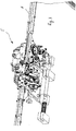
- a strapping device 1 is shown, which is provided with a control 2, a storage device 3 for storing and providing a strapping band, as well as with a strapping head 5.
- the strapping head 5 is used, among other things, to generate a feed as well as to Creation of a retraction movement of the strapping band. It is also provided with a tensioning device for applying tape tension to a tape loop, as well as a locking device for creating a lock on the strapping band.
- the strapping device has a tape guide 6 with which the tape can be placed around a packaged item 7 mechanically and automatically on a predetermined path.
- a welding and clamping unit 16 is integrated into the strapping head 5. Except for the strapping head 5, these are components of strapping devices that are known per se.
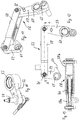
- the arranged together with the tape guide 6 on a frame 8 and in Fig. 2 Strapping head 5 shown separately has a tape drive device 15.
- Belt drive devices are basically previously known, which is why the differences to previously known belt drive devices will essentially be discussed below.
- the belt drive device according to this exemplary embodiment can, in particular, have one or more pairs of rollers 11, 12; 13 and possibly be provided with further individual pulleys. The latter, however, do not take part in the generation of the tape movement and are only provided for determining the direction of the tape run.
- the rollers 11, 12, 13 in the exemplary embodiment which generate the tape movements, at least one of the rollers 11, 12, 13 should be motor-driven to generate a tape feed or tape return movement.
- a roller 11, 12, 13 of the roller pairs formed from these rollers should preferably be driven, between which the strapping is carried out and a feed, retraction or tensioning movement and, if necessary, a chipping movement is transmitted to the tape.
- the strapping head 5 has two components, a control component 16 and a strap handling component 17.
- the control component 16 has other functions in addition to executing control functions for the components of the strapping device, for example the creation of closures between the two strap layers of a strapping as well as cutting of the strapping tape from the tape supply.
- the control component 16 is mounted on a partial carrier 18 of the strapping head, the partial carrier 18 is in turn releasably attached to a common main carrier 19 of the strapping head 5.
- the partial carrier 18 of the control component 16 can be pivoted about an axis 23.
- the elements of the strap handling component 17 are attached directly to the main beam 19 of the strapping head without their own sub-beams.
- the control component 16 is essentially provided for the execution of control and coordination functions of the functions carried out with the strapping head.
- the strap handling component 17 and the components attached to it are intended to act directly on the strapping strap.
- a tape feed device 20, a tape retraction device 21 and a tensioning device 22 are integrated into the tape handling component 17 of the strapping head 5.
- rollers 11, 12; 13 provided. Of the total of only three rollers 11, 12, 13, two rollers 11, 12 are motor-driven rollers.
- the two rollers 11, 12 are driven by the same (only one) motor 14, in the exemplary embodiment an electric motor.
- a drive train can be guided from the common motor 14 to one of the two rollers 11, 12, for example.
- the roller 11 is provided both as a drive wheel for the tape feed (tape feed wheel) and as a drive wheel for the tape retraction (tape retraction wheel).
- the roller 11 can be driven in both directions of rotation by the same drive motor 14.
- the counterclockwise direction of rotation is the tape feed direction and the clockwise direction of rotation is the tape retraction direction.
- the motor drive movement is transmitted to both wheels or rollers 11, 12 from the common motor 14 by means of a transmission device.
- the transmission device 14a comprises a toothed belt transmission which transmits the drive movement from the motor shaft to a further shaft running parallel to the motor shaft. On this further shaft, two gears are arranged, each of which belongs to a further of two sub-transmissions of the transmission device.
- the Motor drive movement is transmitted to the roller or the wheel 11 and from the other partial transmission to the tensioning wheel 12.
- both the tensioning wheel 12 and the wheel 11 rotate in different directions of rotation in the exemplary embodiment.
- the roller 11 is arranged above the roller 12.
- the roller 12 is part of the tensioning device 22 and has the function of the tensioning wheel. It has a significantly larger diameter than the roller 11.
- the tensioning wheel 12 can also be driven in both directions of rotation due to the rigid connection with the motor 14 and the drive movements carried out by the motor in both directions of rotation. However, only the drive movement in the tensioning direction is used by the tensioning wheel, ie based on the illustration of FIG Fig. 6 the direction of rotation clockwise.
- a relaxation of the strap section located in the strapping head and no longer belonging to the strap loop can take place.
- the drive movements for both the tensioning movement and the relaxation movement come from the same drive motor as for the roller 11.
- a switchable coupling can be used in the drive train not shown in detail provided, with which the drive movement can be directed either to the roller 11 or the roller 12.
- the tensioning wheel can in turn be driven in both directions of rotation, it can also be provided that the tensioning wheel can also only be driven in the direction of rotation intended for the tensioning process.
- roller 13 is adjacent to both the roller 11 and the tensioning wheel 12.
- the roller 13 is not rotationally driven and is articulated so as to be pivotable by means of a pivoting device.
- the swivel device is operatively connected to a drive, by means of which the roller can execute (motor-driven) swivel movements.
- the Counter-roller acting roller 13 can either be brought into abutment against roller 11 or in abutment against tensioning wheel 12, the strapping band being located between one of the rollers 11, 12 and the roller 13 in the respective end position of the pivotable roller 13.
- the counter-roll 13 Depending on which of the rollers 11, 12 the counter-roll 13 rests against, the counter-roll 13 then presses the belt against the corresponding roll 11, 12, so that the corresponding roll 11, 12 rotates with as little slippage as possible as a feed, retraction or tensioning movement and, if necessary, can be transferred to the strapping band as a relaxation movement.
- the counter roller 13 is thus, together with the roller 11, both a component of the tape feed device and a component of the tape retraction device. Together with the tensioning wheel 12, the counter roller 13 is also part of the tensioning device 22.
- This preferred embodiment according to the invention makes it possible to avoid the fourth roller, which was previously common in previously known solutions. In these previously known solutions, one of two counter-rollers is permanently assigned to the drive roller and the tensioning wheel. In contrast, the preferred 3-roller solution according to the invention can enable a significantly more compact design.
- the rollers 11, 12, 13 are also part of a band guide channel 28 in the strapping head 5, through which the course as well as the advance and retraction path of the band is predetermined.
- the tape guide channel 28 is in turn part of the tape guide 6.
- the strapping head 5 has a first interface 29, at which the strapping head 5 connects to the supply roll side of the tape guide.
- the one end of the tape guide channel 28 formed here is designed as a quick-change interface.
- This has a channel piece 31 which can be clamped to the strapping head by means of a pivotable clamping lever 30 and through which the tape is fed into the strapping head.
- the channel piece 31 ends immediately in front of the circumferential surface 11a of the roller 11, so that the strapping tape can be fed at least approximately tangentially to the circumferential surface 11a of the roller 11. If the roller 13 is in its end position pivoted relative to the roller 11, the tape is passed through between the rollers 11, 13, the roller 13 pressing the tape against the roller 11.
- the tape When viewed in the direction of tape advance 32, the tape proceeds to the tensioning wheel 12 as it continues.
- a circular arc-shaped channel section 28a extending over approximately 180 ° on the circumference of the tensioning wheel 12 is formed by suitable channeling means.
- the channel section 28a With regard to the strip thickness, the channel section 28a is made significantly wider than the strip thickness.
- the inner delimitation of the channel section is formed by the section of the circumferential surface 12a of the tensioning wheel 12 which is located in the region of the channel section.
- the outer boundary of the channel section 28a in the radial view has guide plates as well as an outer channel segment which can be pivoted together with the counter roller 13 and with which the outer channel section can be kept closed although the pivotable counter roller 13 is located in the area of the outer channel section. Without the pivotable channel segment 33 or another similarly acting element, at least one of the two pivot end positions of the counter roller 13 would possibly result in an open position in the channel section, which could possibly have a negative effect on reliable tape guidance.
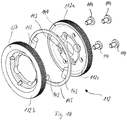
- the tensioning wheel is shown in three representations. This has a ring 37 which is provided with a recess 38 which is provided for connecting the tensioning wheel 12 to a shaft of the drive, in particular to a shaft of a transmission of the drive.
- Fig. 2 the tensioning wheel 12 mounted on the shaft is shown.
- the circular tensioning wheel is provided with a circumferential surface 12a of at least substantially constant width.
- the tensioning wheel 12 is provided on its circumferential surface 12a with knurling or toothing 39, by means of which the engagement conditions of the tensioning wheel 12 on the strapping band are improved.
- any other geometrically determined or indefinite roughening of the circumferential surface 12a of the tensioning wheel could be provided, with which a possible slip between the tensioning wheel and the strapping can be prevented at least as far as possible during the tensioning process.
- a groove 40 with a comparatively small width is introduced, which is formed significantly deeper than it is wide.
- the groove 40 are located in Embodiment two rubber-elastic O-rings 43, 44 one above the other, which are arranged radially one behind the other in the groove 40.
- one of the O-rings 43 is arranged with a smaller and the other O-rings 44 with a, in comparison, larger distance to the axis of rotation of the tensioning wheel 12.
- the width of the O-rings 43, 44 is provided in such a way that they correspond approximately to the width of the groove 40.
- the two O-rings 43, 44 are located completely within the groove 40.
- Both O-rings 43, 44 are made of rubber-elastic material.
- a ring 45 provided as a spacer element sits on the outer of the two O-rings 43, 44 and is made of a metallic material in the exemplary embodiment.
- the ring 45 is elastically deformable in this embodiment.
- the ring could be designed to be essentially rigid or dimensionally stable.
- the ring 45 could also be formed from one or more materials other than a metallic material, for example from an elastic plastic.
- this metal ring 45 is provided with a smaller width B than height H in relation to its cross section.
- the height of the O-ring is matched in relation to the groove depth and the height of the O-rings in such a way that the ring protrudes from the groove 40 with a height H 1.
- the ring 45 is thus in its in Fig. 9 shown unloaded state over the circumferential surface 12a of the clamping ring 12, in particular over its entire circumference or over the entire circumference of the clamping ring 12.
- the strapping tape is pushed from the strapping head 5 with its free tape end first through the tape guide 6, preferably at high speed.
- the counter roller 13 is in contact with one side of the belt.
- the tape is pressed with its other side against the motor-driven roller 11 by the counter roller.
- the rotary drive movement of the roller 11 in the feed direction is hereby transmitted to the strapping, which causes its feed movement in the feed direction.
- the tape comes into contact with the tensioning wheel 12 behind the run-out area of the tape from the gap between the roller 11 and the counter roller 13, but without exerting any appreciable pressure on the tensioning wheel 12.
- the end of the tape reaches the closure head again.
- the end of the tape activates a limit switch, whereby the feed movement is stopped and the end of the tape is clamped.
- the camshaft control of the control component 16 now sets the roller 11 in motion in the opposite direction of rotation to the feed direction.
- the strapping band which is still clamped between the roller 11 and the counter roller 13, is thereby moved in the opposite direction, that is to say in the band retraction direction 48.
- the circumferential length of the tape loop, the tape end of which is still clamped, is thereby continuously shortened. As a result, the tape is torn from the tape guide 6 and, as a result, applied around the respective packaged goods.
- Fig. 6 the tensioning wheel 12 is shown during the tape retraction process.
- the strap comes into contact with the tensioning wheel 12 during the tape retraction process.
- the strapping band rests on the tensioning wheel 12 for the most part over the entire arcuate channel section 28a, similar to the one that is also the case with the subsequent tensioning process.
- the tape is withdrawn here, but due to its ability to yield to this movement by moving out of the tape guide as intended, only a comparatively low tape tension is applied to the tape of the tape loop during this phase.
- the band does not lie on the circumferential surface of the tensioning wheel 12 but on the ring 45 located in the circumferential surface 12a.
- This contact with the spacer element which is embodied here as a ring 45 in the exemplary embodiment, means that the band cannot be damaged by the knurling or toothing 39 of the peripheral surface 12a during the band retraction.
- the control switches from tape retraction to generating a tape tension, whereby the tape lying against the packaged goods is to be pulled tight.
- the counter roller 13 is first pivoted from its contact position against the roller 11 into a contact position against the tensioning wheel 12.
- the tensioning wheel 12 offset in the same direction of rotation as before the roller 11, rotates at a lower speed but using a greater torque and pulls further on the strapping band.
- the belt is no longer in contact with the roller 11, which is still driven and rotating faster in the exemplary embodiment, in such a way that the roller 11 could transfer its movement to the belt.
- the tape Since the strapping tape is already in contact with the packaged goods at this stage, the tape is pulled back by the tensioning wheel 12 at most with a short length compared to the tape retraction phase. During this tensioning phase, a greater tension is primarily applied to the tape.
- the pressure of the counter roller 13 in the direction of the tensioning wheel and the belt located in between pushes the ring 45 in the direction of the groove base and thus also in the essentially radial direction in the direction of the axis of rotation of the tensioning wheel 12.
- the band rests against the ring 45 and also presses it at least in the area of the counter roller 13 in the direction of the groove base.
- the ring 45 is thus already at a smaller distance from the axis of rotation of the tensioning wheel at the beginning of the tensioning process than in its unloaded state, for example during the tape advance or retraction phase.
- the greater torque transmitted from the tensioning wheel 12 to the belt in the further course of the tensioning process compared to the belt retraction phase of the roller 11 results in a greater reaction force of the belt.
- This greater reaction force now means that the band presses the ring 45 into the groove not only in the contact area with the counter roller 13, but also over its contact length (wrap angle, seen in the circumferential direction) with the ring 45, whereby the band now along its wrap angle on the Tensioning wheel 12 rests against its peripheral surface.
- the ring 45 can protrude from the circumferential surface to a greater extent than in comparison to the unloaded state in which it protrudes a height H 1.
- each individual point of the ring is alternately pressed into the groove 40 and emerges from it again until, due to the rotation of the tensioning wheel, the Reached point at which the band wraps around a section of the circumferential surface and thereby presses the ring along this section into the groove.
- the counter roller 13 can advantageously be pressed against the roller 11 (feed roller or retraction roller) on the one hand and against the tensioning wheel 12 on the other hand with different pressure forces (when the strapping device is in use, each with a strapping band in between).
- higher pressing forces against the tensioning wheel can be advantageous for high functional reliability and the possibility of applying high band tensions to the strapping band.
- the counter roller 13 is arranged on an eccentric 50, which in turn is arranged on a shaft 51 of a carrier 52.
- the carrier has a receptacle 53 which is provided for arrangement on the bearing point 54 of the roller 11 ( Fig. 5 , 6th ).
- the receptacle 53 is freely rotatable about its axis of rotation on the bearing point 54 of the roller 11 and can thus execute pivoting movements about its axis of rotation.
- the parallelogram 56 has a long vertical lever 57, a horizontal lever 58 and a short vertical lever 59.
- the parallelogram is pivotably articulated on the long vertical lever 57 and on the short vertical lever 59.
- the levers 57 and 59 have pivot bearing points 60, 61 for this purpose.
- a rotary movement can be transmitted to the long vertical lever 57 via a bell curve 62, which movement leads to the pivoting movement of the lever 57 about its pivot bearing point 60.
- the pivoting movement of the lever 57 takes place in a clockwise direction.
- the lever 58 thereby pulls the latter towards the lever 57 at the articulation point of the short vertical lever, as a result of which the vertical lever 59 in the illustration of FIG Figures 11, 12 also pivots clockwise about its pivot bearing point 62.
- An inclined surface 64 formed on the short vertical lever 59 thereby presses on a bearing 51 arranged on the shaft 51.
- the inclined surface thereby moves in a clockwise direction (as shown in FIG Fig. 12 ) and tends to be horizontal.
- the carrier 52 executes a pivoting movement, as a result of which the counter roller 13 is pivoted from its end position against the roller 11 in the direction of the tensioning wheel 12.
- the parallelogram can be reset by a further spring 73 arranged on the pin 72 of the lever 5.
- a tensioning wheel 112 according to the invention is shown.
- the tensioning wheel 112 can be longitudinally divided with respect to its width, preferably approximately in the middle, the two parts 112b, 112c of the tensioning wheel 112 being releasably connectable to one another by means of suitable fastening elements, for example screws 114.
- a circumferential groove 140 is formed in the outer ring 137 of the tensioning wheel 112, which is open towards the circumferential surface 112a of the tensioning wheel 112 and tapers or decreases in the direction towards this.
- One or more restoring elements can be arranged in the groove 140.
- elastic ring sections 143 for example a plurality of rubber-elastic O-ring sections 143, are arranged as the restoring element. These ring sections are preferably evenly distributed in the groove 140 at a distance from one another, as is the case in the exemplary embodiment with a total of four ring sections 143.
- the restoring elements 143 are located below one or more spacer elements. In the exemplary embodiment, only a spacer element 145 designed as a closed ring is provided.
- An outer diameter of the ring 145 arranged in the groove is dimensioned in such a way that when the ring 145 is in the unloaded state, its outer circumferential surface protrudes beyond the circumferential surface 112a of the clamping ring 112. With its inner circumferential surface, the ring 145 is located in the groove.
- the restoring elements are attached to the inner circumferential surface of the circular and essentially dimensionally stable ring 145. In other embodiments, a different number of spacer elements and a different number of restoring elements can also be provided.
- the ring 145 which in the exemplary embodiment is essentially non-deformable and thus dimensionally stable due to the expected forces acting on it, is thus arranged slightly eccentrically in relation to the axis of rotation of the tensioning wheel during this process. As a result, the ring 145 protrudes further out of the groove 140 with its section not covered by the wrap angle of the strap than when the tensioning wheel is in the unloaded state of the strapping strap.
- the elastic Restoring forces from one or more of the ring cuts 143 allow the ring 145 to protrude again over its entire circumference from the groove.
- This preferred arrangement allows the ring 145 to be pressed into the groove 140 in sections during the tensioning process, during which the strapping band exerts a sufficiently high pressure force on the ring 145 located in the wrapping area of the strapping band.
- the compressive force on the section of the ring 145 currently arranged in the wrapping area of the band is not sufficiently great to push this ring section completely into the groove 140.
- the band hereby rests against the portion of the ring 145 and not against the surface of the tensioning wheel 112.
- the ring 145 holds the strap at a distance from the circumferential surface of the tensioning wheel 112.
- a further exemplary embodiment for a belt drive device 115 is shown.
- This also has only three rollers 111, 112, 113, which are responsible for applying the tape feed, tape retraction and tape tension movement to the tape through contact with the tape, the two rollers 111 and 112 by means of a motor, in particular by means of only one common motor can be driven.
- the relative arrangement of the axes of rotation of the three rollers 111, 112, 113 to one another corresponds at least approximately to the arrangement of these axes of rotation in the exemplary embodiment of FIG Fig. 5 and 6th .
- the counter roller 113 is in turn designed to be pivotable, so that it is provided in a pivot position for pressing the strapping against the roller 111 and in another pivot position for pressing the strapping against the tensioning roller 112.
- the pivoting mechanism of the counter roller 113 provided for this purpose and its drive can in principle be the same as in the exemplary embodiment of FIG Figs. 1 to 13 be trained.
- the counter roller 113 is as in the embodiment of FIG Fig. 5 and 6th rotatably mounted on an eccentric 150, so that the counter-roller 113 executes a non-circular arc-shaped movement during a pivoting movement from one of the rollers 111, 112 to the respective other roller 111, 112. As in the Fig.
- FIG. 18 and 19th is shown, on the eccentric 150 of the counter roller 113 is a Lifting device 180 supported, the lifting device 180 being supported with a carrier 181 on the frame of the strapping device 101.
- the bearing point 182 of the ventilation device on the eccentric 150 is itself arranged pivotably on the eccentric and is designed as a C-shaped or fork-shaped element 183 in order to thereby form a receptacle for one end of a piston 184.
- This piston 184 is arranged displaceably in the carrier 181 of the ventilation device 180.
- the support point is shown in Fig. 18 and 19th directly above the roller 111.
- the support 181 of the ventilation device is also pivotably mounted here.
- the ventilation device 180 is provided with a ventilation element which is provided to execute a controlled movement with which the counter roller 113 is acted upon in order to lift the counter roller 113 in its pivoted position on the roller 111 or to lift it slightly.
- the counter-roller 113 should be able to be positioned in its pivoted position on the roller 111 again after a ventilation, for example likewise by means of the ventilation device.
- the ventilation element is designed as a lifting magnet 186 which is arranged and mounted on the ventilation device 180. The lifting magnet 186 can execute a linear lifting movement with its piston 184 along the longitudinal axis 184a of its piston 184. As in Fig.
- one end of the piston 184 is arranged in the recess of the C-shaped or fork-shaped element 183, which is open towards the carrier 181.
- the end of the piston 184 and the recess of the C-shaped element can be designed in such a way that, during the ventilation movement, the end of the piston 184 in the C-shaped element can move relative to the latter.
- the elongated longitudinal axis 184a of the piston 184 runs at least approximately through the articulation point of the C-shaped element 183.
- a stroke movement of the piston 184 in the direction of the counter roller 113 thus leads to a rotary movement of the eccentric about its axis of rotation.
- the rotational movement of the eccentric 150 in turn results in the axis of rotation of the counter roller 113 being displaced in parallel and a gap or a gap between the roller 111 and the counter roller 113 increased gap results.
- the width of the gap here should have a size that is greater than the thickness of the respective strapping band being processed.
- the product GKb-32.06 from Isliker Magnete AG, CH-8450 Andelfingen, for example, can be used as a lifting magnet.
- a mechanical spring element can be arranged on the piston 184, in particular at least one compression spring 188.
- This compression spring 188 is compressed during the movement of the counter roller 113 by the tension roller 112 to rest against the roller 111 and thus tensioned in a resilient manner.
- the electrically operated magnetic reciprocating piston is switched off in this phase and therefore has no effect.
- the compression spring 188 is at least partially relaxed and the spring force supports the force exerted by the lifting magnet, with which the piston 184 is moved by the roller 111 to release the counter roller 113.
- the lifting magnet or another restoring element alone provides a force that is sufficiently high for the ventilation process.
- the tape is moved through the tape guide channel 28 in the feed direction by means of the roller 111 and the counter roller 113 resting against it and clamping the tape between the two rollers.
- the tape hits a stop or the reaching of the end of the tape guide channel can be detected in another way, for example by a light barrier.
- This generates a signal by which the control of the strapping device stops the motorized drive movement of the roller 111 and - at least essentially at the same time - triggers the stroke movement of the piston 184 of the lifting magnet.
- the stop of the drive movement of the roller 111 and the start of the ventilation process are offset in time, i.e. the stop of the drive movement occurs before or after the start of the ventilation process.
- the piston 184 extends in the direction of the C-shaped element 183 and hereby acts with its end on the C-shaped or fork-shaped element. Due to its arrangement on the eccentric 150, the eccentric is rotated during the stroke movement of the piston. In the exemplary embodiment and in the illustration of Fig. 18 the rotary movement of the eccentric takes place by an angle of rotation less than 90 ° in the counterclockwise direction. The rotary movement takes place against the spring force of the pressure spring 190, which is compressed in the process and is also articulated on the eccentric 150. As a result of the rotary movement, the counter roller 113 is lifted from the roller 111, ie raised and the distance between the two rollers 111, 113 is increased so that a gap is created between the rollers which is greater than the belt thickness.
- the strapping tape shot through the tape channel of the tape guide 6 at high speed has the tendency to form waves between the rollers 111, 112, 113 and the end of the strapping channel due to the sudden and abrupt tape stop in generic strapping devices.
- such waves can lead to malfunctions.
- the tape Due to the preferred embodiment according to the invention, in which the counter roller 113 is lifted, the tape can move back as far as necessary and freely against the feed direction in the direction of the tape supply, especially immediately after the feed has stopped, so that the tape supply for the length of the tape channel may move can move back excess and the wave formation causing tape portion in the tape guide channel.
- the control of the strapping device can then switch off the lifting magnet again.
- the solenoid loses its effect, which means that the pressure spring 190 can move the eccentric 150 back against the direction of rotation and thus bring the counter-roller 113 back into contact position against the belt, in which the belt is clamped between the roller 111 and the counter-roller 113.
- the subsequent tape retraction and tensioning process can be carried out in the same way as in the embodiments of the invention according to FIGS Figs. 1 to 13 respectively.
Claims (14)
- Tête de cerclage (5), ou élément de cerclage, d'un dispositif de cerclage (1) permettant de cercler des produits emballés à l'aide d'une bande de cerclage, en particulier d'une bande de cerclage en matière plastique, qui est munie d'un élément d'avance et d'un élément de tensionnement (20, 22) qui sont équipés de plusieurs roues (11, 12, 13 ; 111, 112, 113) pour transférer un mouvement d'avance, de recul et de tensionnement sur la bande de cerclage, dans laquelle au moins l'une de ces roues est ou peut être mise en liaison fonctionnelle avec un élément d'entraînement afin de mettre ladite au moins une des roues en mouvement de rotation autour d'un axe de rotation pour le mouvement d'avance, de recul et de tensionnement,
dans laquelle un moyen pouvant être actionné est prévu qui permet de commuter au moins une roue (13, 113) d'une paire de roues de l'élément d'avance (20) sur un état dans lequel la bande de cerclage, sans qu'aucun mouvement d'entraînement motorisé ne soit transmis à la bande de cerclage, peut être déplacée entre la paire de roues dans une direction opposée au mouvement d'avance de bande ;
caractérisée en ce qu'au moins l'une des roues (11) peut être entraînée dans les deux sens de rotation par le même moteur d'entraînement (14). - Tête de cerclage selon la revendication 1, caractérisée en ce que le moyen comprend un élément pneumatique (180) au moyen duquel les deux roues disposées sous forme de paire de roues entre lesquelles la bande de cerclage peut être serrée pour la transmission de mouvement et dont une roue peut être entraînée par moteur, peuvent être disposées temporairement à une distance l'une par rapport à l'autre, qui permet un mouvement, en particulier un mouvement libre, de la bande de cerclage entre les deux roues dans une direction opposée au mouvement d'avance de bande (32).
- Tête de cerclage selon l'une quelconque des revendications précédentes, caractérisée en ce que la paire de roues est prévue pour appliquer le mouvement d'avance de bande à la bande de cerclage et pour appliquer le mouvement de recul de bande à la bande de cerclage.
- Tête de cerclage selon l'une quelconque des revendications précédentes, caractérisée par des moyens qui permettent d'actionner l'élément pneumatique (180) en fonction d'une position du début de bande de la bande de cerclage lorsqu'une boucle de bande est formée.
- Tête de cerclage selon l'une quelconque des revendications précédentes, caractérisée par un moyen de détection par lequel l'arrivée à une certaine position du début de bande est détectée lorsqu'une boucle de bande est formée, et en raison de cette détection, l'élément pneumatique (180) peut être actionné par une unité de commande de la tête de cerclage (5).
- Tête de cerclage selon la revendication 5, caractérisée par une distance entre les surfaces circonférentielles des deux roues (11, 13 ; 12, 13 ; 111, 113 ; 112, 113) qui peut être obtenue en raison d'un actionnement de l'élément pneumatique (180), dans une plage de 1,5 à 10 fois l'épaisseur de bande, de préférence dans une plage de 2 à 8 fois l'épaisseur de bande, et de manière particulièrement préférée dans une plage de 3 à 7 fois l'épaisseur de bande.
- Tête de cerclage selon l'une quelconque des revendications précédentes, caractérisée en ce que ladite une roue (11, 12, 13 ; 111, 112, 113) de la paire de roues est disposée sur un excentrique (50, 150), et le moyen pouvant être actionné permet d'effectuer un mouvement de rotation de l'excentrique (50, 150) dans un premier sens de rotation, de sorte qu'une distance des deux roues (11, 13 ; 12, 13 ; 111, 113 ; 112, 113) de la paire de roues augmente.
- Tête de cerclage selon la revendication 7, caractérisée en ce que l'excentrique (50, 150), après le mouvement de rotation dans le premier sens de rotation, est ensuite disposé de manière à pouvoir tourner dans un deuxième sens de rotation afin de réduire à nouveau la distance des roues (11, 13 ; 12, 13 ; 111, 113 ; 112, 113) de la paire de roues.
- Tête de cerclage selon l'une quelconque des revendications précédentes, caractérisée en ce que le moyen comprend un moyen d'accouplement pour séparer une liaison fonctionnelle d'une des roues (11, 12, 13 ; 111, 112, 113) de la paire de roues de son dispositif d'entraînement qui permet à la roue (11, 12, 13 ; 111, 112, 113) de tourner librement autour de son axe de rotation.
- Tête de cerclage selon l'une quelconque des revendications précédentes, caractérisée en ce que pour le contact avec la bande de cerclage lorsque le mouvement d'avance, de recul et de tensionnement est effectué, au total un maximum de trois roues (11, 12, 13 ; 111, 112, 113) est prévu sur la tête de cerclage (5), qui entrent en contact avec la bande de cerclage dans le cadre de ces fonctions, le maximum de trois roues (11, 12, 13 ; 111, 112, 113) pouvant être amené en différentes combinaisons les unes avec les autres respectivement par paires sur deux côtés de la bande de cerclage en appui sur la bande de cerclage.
- Tête de cerclage selon la revendication 10, caractérisée en ce qu'au moins l'une des trois roues (11, 12, 13 ; 111, 112, 113), de préférence une seule des trois roues (11, 12, 13 ; 111, 112, 113), peut être déplacée en alternance en direction de respectivement l'une des deux autres roues pour être en appui avec respectivement une autre roue sur la bande dans une position de fin de mouvement, dans laquelle la roue mobile est prévue pour effectuer des mouvements pivotants, en particulier des mouvements pivotants entraînés, est disposée en pouvant tourner librement autour de son axe de rotation, et est en liaison fonctionnelle avec un dispositif d'entraînement pour effectuer son mouvement en direction d'une des deux roues.
- Tête de cerclage selon l'une quelconque des revendications précédentes, caractérisée en ce qu'une première roue est réalisée comme roue de tensionnement (12, 112) de l'élément de tensionnement et une deuxième roue (11, 111) est réalisée comme roue commune de l'élément d'avance de bande et de l'élément de recul de bande (20, 21), la première et la deuxième roue (11, 111; 12, 112) sont ou peuvent être mises en liaison fonctionnelle avec un dispositif d'entraînement commun ou avec plusieurs dispositifs d'entraînement pour générer des mouvements de rotation entraînés de la première et de la deuxième roue, et la troisième roue (13, 113) mobile par rapport à leur position, est disposée de manière mobile entraînée entre des positions d'appui sur la première et la deuxième roue.
- Tête de cerclage selon l'une quelconque des revendications précédentes, caractérisée en ce que ladite au moins une roue (13, 113) effectue un mouvement excentrique combiné avec un mouvement pivotant.
- Dispositif de cerclage, comprenant une tête de cerclage selon l'une quelconque des revendications précédentes, caractérisé en ce que pour l'avance de bande, le recul de bande et pour l'application de la tension de bande sur la boucle de bande, trois roues (11, 12, 13 ; 111, 112, 113), en particulier trois roues (11, 12, 13 ; 111, 112, 113) seulement, sont prévues, dans lequel une première roue (11, 111) peut être entraînée par moteur dans deux sens de rotation différents et est prévue comme un rouleau d'avance de bande et un rouleau de recul de bande, une deuxième roue, qui est prévue comme roue de tensionnement (12, 112), peut être entraînée par moteur dans au moins un sens de rotation, de préférence dans les deux sens de rotation, et la troisième roue (13, 113), qui de préférence n'est pas entraînée par moteur en rotation autour de son axe de rotation, est prévue comme contre-roue (13, 113) et peut être déplacée en alternance contre la première roue (11, 111) ou contre la deuxième roue (12, 112), dans lequel, au moyen de l'élément pneumatique (180), la position de la contre-roue (13, 113) peut être modifiée pour générer un interstice entre les surfaces circonférentielles de la première roue (11) et de la contre-roue (13, 113) pour un mouvement libre de la bande de cerclage entre la première roue (11, 111) et la contre-roue (13, 113) pour former un interstice, et peut ensuite être ramenée à la première roue (11, 111), en particulier avant que la contre-roue (13, 113) ne soit rapprochée de la roue de tensionnement (12, 112).
Priority Applications (1)
| Application Number | Priority Date | Filing Date | Title |
|---|---|---|---|
| PL15711037T PL3105128T3 (pl) | 2014-02-10 | 2015-02-10 | Urządzenie do taśmowania z urządzeniem do przesuwu taśmy w przód |
Applications Claiming Priority (4)
| Application Number | Priority Date | Filing Date | Title |
|---|---|---|---|
| CH00181/14A CH709244A2 (de) | 2014-02-10 | 2014-02-10 | Spanneinrichtung einer Umreifungsvorrichtung zur Umreifung von Packgut mit einem Umreifungsband. |
| CH00182/14A CH709245A2 (de) | 2014-02-10 | 2014-02-10 | Umreifungseinrichtung einer Umreifungsvorrichtung zur Umreifung von Packgut mit einem Umreifungsband. |
| CH00183/14A CH709246A2 (de) | 2014-02-10 | 2014-02-10 | Umreifungseinrichtung einer Umreifungsvorrichtung zur Umreifung von Packgut mit einem Umreifungsband. |
| PCT/CH2015/000016 WO2015117257A1 (fr) | 2014-02-10 | 2015-02-10 | Système de cerclage comprenant un dispositif d'avancement de bande |
Publications (2)
| Publication Number | Publication Date |
|---|---|
| EP3105128A1 EP3105128A1 (fr) | 2016-12-21 |
| EP3105128B1 true EP3105128B1 (fr) | 2021-04-28 |
Family
ID=52697174
Family Applications (4)
| Application Number | Title | Priority Date | Filing Date |
|---|---|---|---|
| EP15711034.7A Active EP3105126B1 (fr) | 2014-02-10 | 2015-02-10 | Dispositif de tension pour dispositif de cerclage |
| EP15711037.0A Active EP3105128B1 (fr) | 2014-02-10 | 2015-02-10 | Système de cerclage comprenant un dispositif d'avancement de bande |
| EP15711035.4A Active EP3105127B1 (fr) | 2014-02-10 | 2015-02-10 | Système de cerclage |
| EP15711036.2A Active EP3105129B1 (fr) | 2014-02-10 | 2015-02-10 | Système de cerclage |
Family Applications Before (1)
| Application Number | Title | Priority Date | Filing Date |
|---|---|---|---|
| EP15711034.7A Active EP3105126B1 (fr) | 2014-02-10 | 2015-02-10 | Dispositif de tension pour dispositif de cerclage |
Family Applications After (2)
| Application Number | Title | Priority Date | Filing Date |
|---|---|---|---|
| EP15711035.4A Active EP3105127B1 (fr) | 2014-02-10 | 2015-02-10 | Système de cerclage |
| EP15711036.2A Active EP3105129B1 (fr) | 2014-02-10 | 2015-02-10 | Système de cerclage |
Country Status (7)
| Country | Link |
|---|---|
| US (4) | US10220971B2 (fr) |
| EP (4) | EP3105126B1 (fr) |
| CH (4) | CH709220A2 (fr) |
| ES (1) | ES2883950T3 (fr) |
| PL (4) | PL3105129T3 (fr) |
| TR (1) | TR201905484T4 (fr) |
| WO (4) | WO2015117256A1 (fr) |
Families Citing this family (5)
| Publication number | Priority date | Publication date | Assignee | Title |
|---|---|---|---|---|
| US10220971B2 (en) | 2014-02-10 | 2019-03-05 | Signode Industrial Group Llc | Tensioning device for a strapping device |
| US10569914B2 (en) * | 2016-06-01 | 2020-02-25 | Signode Industrial Group Llc | Shock absorbing feed wheel assembly |
| IT201700005654A1 (it) * | 2017-01-19 | 2018-07-19 | Messersi Packaging Srl | Macchina reggiatrice con gruppo perfezionato di movimentazione della reggia |
| EP3556667B1 (fr) * | 2018-04-19 | 2021-04-14 | TITAN Umreifungstechnik GmbH & Co.KG | Dispositif de cerclage |
| EP3960642B1 (fr) * | 2020-08-28 | 2024-04-17 | Signode Finland Oy | Système d'alimentation automatique de bandes de cerclage pour alimenter en bandes une machine de cerclage |
Citations (12)
| Publication number | Priority date | Publication date | Assignee | Title |
|---|---|---|---|---|
| JPS5723611B2 (fr) | 1976-12-22 | 1982-05-19 | ||
| EP0061620A2 (fr) | 1981-03-24 | 1982-10-06 | OFFICINA MECCANICA SESTESE S.p.A. | Dispositif d'alimentation et de mise sous tension d'un ruban d'emballage dans des machines de ficelage |
| EP0095643A2 (fr) | 1982-05-29 | 1983-12-07 | Hoesch Aktiengesellschaft | Dispositif d'avancement et de tensionnement pour un lien de cerclage qui doit être tendu autour d'un paquet |
| EP0337782A1 (fr) | 1988-04-15 | 1989-10-18 | Signode Kabushiki Kaisha | Dispositif à cercler à l'aide d'un ruban |
| EP0337781A1 (fr) | 1988-04-15 | 1989-10-18 | Signode Kabushiki Kaisha | Dispositif à cercler à l'aide d'un ruban |
| EP0603868A1 (fr) | 1992-12-23 | 1994-06-29 | OFFICINA MECCANICA SESTESE S.p.A. | Dispositif de commande d'alimentation de ruban dans une machine de cerclage |
| US5379576A (en) | 1992-06-10 | 1995-01-10 | Strapack Corporation | Band feeding and tightening apparatus for packing machine |
| US6041698A (en) | 1999-03-17 | 2000-03-28 | Tekpak Corporation | Guide band packaging machine |
| WO2001038175A1 (fr) | 1999-11-25 | 2001-05-31 | Macpro S.A.S. Di Alberto Galli & C. | Dispositif de tensionnement pour machines a lier |
| DE10026200A1 (de) | 2000-05-26 | 2001-11-29 | Cyklop Gmbh | Vorrichtung zum Spannen von Umreifungsbändern |
| EP1177978A1 (fr) | 2000-07-31 | 2002-02-06 | Strapack Corporation | Procédé et appareil de cerclage pour système d'emballage |
| EP1357033A2 (fr) | 2002-04-23 | 2003-10-29 | TITAN Umreifungstechnik GmbH & Co.KG | Appareil pour encercler des marchandises avec une bande |
Family Cites Families (177)
| Publication number | Priority date | Publication date | Assignee | Title |
|---|---|---|---|---|
| US2194108A (en) | 1935-11-30 | 1940-03-19 | Acme Steel Co | Box strapping machine |
| US2707429A (en) | 1948-09-09 | 1955-05-03 | Signode Steel Strapping Co | Automatic strapping machine |
| US3120171A (en) | 1958-01-28 | 1964-02-04 | Acme Steel Co | Automatic strapping machine |
| US3232217A (en) | 1964-05-04 | 1966-02-01 | Stanley Works | Strapping machine |
| US3367374A (en) | 1965-04-08 | 1968-02-06 | Signode Corp | Gripper plug |
| FR1513685A (fr) | 1966-02-02 | 1968-02-16 | Signode Corp | Appareil perfectionné pour cercler des objets au moyen de bandes de cerclage en matière thermoplastique |
| GB1161827A (en) * | 1966-11-29 | 1969-08-20 | Naigai Seikosho Kk | Band Feeding and Tightening Device of Automatic Strapping Machines. |
| US3526187A (en) | 1968-10-02 | 1970-09-01 | Signode Corp | Toggle controlled strapping apparatus and method |
| US3566778A (en) * | 1969-01-27 | 1971-03-02 | Signode Corp | Strap feeding and tensioning system |
| US3654033A (en) | 1970-04-01 | 1972-04-04 | Signode Corp | Strap tensioning and sealing tool |
| JPS5423999Y2 (fr) | 1975-12-27 | 1979-08-15 | ||
| US4011807A (en) | 1976-01-21 | 1977-03-15 | Signode Corporation | Strap feeding and tensioning machine |
| US4015643A (en) | 1976-01-21 | 1977-04-05 | Signode Corporation | Tensioning tool with self-energizing gripper plug |
| US4050372A (en) | 1976-01-21 | 1977-09-27 | Signode Corporation | Automatic strapping machine |
| US4120239A (en) * | 1977-03-10 | 1978-10-17 | Ovalstrapping, Inc. | Strapping machine |
| JPS5953143B2 (ja) | 1977-06-07 | 1984-12-24 | 旭化成株式会社 | 連続鋳造用鋳型 |
| JPS5839790B2 (ja) | 1977-06-21 | 1983-09-01 | 川崎重工業株式会社 | セメントクリンカの焼成装置 |
| DE2818325C2 (de) | 1978-04-26 | 1994-08-18 | Ovalstrapping Inc | Bindemaschine |
| GB2041869B (en) | 1979-02-23 | 1982-12-08 | Nichiro Kogyo Kk | Band feeding and tightening method and device for strapping machinqe |
| US4240865A (en) | 1979-06-25 | 1980-12-23 | Interlake, Inc. | Apparatus and method for applying plastic strap |
| ZA804443B (en) | 1979-07-30 | 1981-07-29 | Signode Corp | All electric friction fusion strapping tool |
| US4313779A (en) | 1979-07-30 | 1982-02-02 | Signode Corporation | All electric friction fusion strapping tool |
| US4535730A (en) | 1980-12-08 | 1985-08-20 | Allen Dillis V | Rocker engine |
| DE3118710A1 (de) | 1981-05-12 | 1982-12-09 | Cyklop International Emil Hoffmann KG, 5000 Köln | Vorrichtung zum spannen, verschliessen und abschneiden von kunststoffbaendern fuer packstueckumreifungen |
| KR880002177B1 (ko) | 1982-11-15 | 1988-10-17 | 마쓰소노 히사미 | 산성유(乳) 음료의 제조법 |
| US4502911A (en) | 1983-07-27 | 1985-03-05 | Cyklop International Emil Hoffman, Kg | Strapping machine |
| US4572064A (en) | 1984-05-23 | 1986-02-25 | Burton R Edward | Brush bundling system |
| CH665604A5 (de) | 1985-01-23 | 1988-05-31 | Strapex Ag | Spann- und verschliessgeraet fuer kunststoffband. |
| CH668402A5 (de) | 1985-03-15 | 1988-12-30 | Konrad Feinmechanik Ag A | Verfahren und maschine zur umreifung eines packgutes mit einem umreifungsband. |
| US4724659A (en) | 1985-12-24 | 1988-02-16 | Nichiro Kogyo Company Ltd. | Band type strapping machine |
| US4707390A (en) | 1986-06-06 | 1987-11-17 | Signode Corporation | Thermoplastic strap weld with encapsulated cavities |
| US4776905A (en) | 1986-06-06 | 1988-10-11 | Signode Corporation | Method and apparatus for producing a welded joint in thermoplastic strap |
| US4912912A (en) | 1987-05-30 | 1990-04-03 | Strapack Corporation | Control apparatus in strapping machine |
| GB8812292D0 (en) | 1988-05-24 | 1988-06-29 | Black & Decker Inc | Improvements in/relating to power tools |
| RU1772784C (ru) | 1989-11-04 | 1992-10-30 | Опытное Конструкторско-Технологическое Бюро С Опытным Производством Института Металлофизики Ан Усср | Устройство дл автоматического управлени приводом |
| JP2740804B2 (ja) | 1990-02-09 | 1998-04-15 | ストラパック株式会社 | 梱包機における空梱包バンドの除去方法 |
| US5628348A (en) | 1990-04-02 | 1997-05-13 | Edge Technology Corporation | Tensioning apparatus |
| DE4014307C2 (de) | 1990-05-04 | 1996-11-07 | Rmo Systempack Gmbh | Packmaschine |
| DE4014305C2 (de) * | 1990-05-04 | 1996-07-18 | Rmo Systempack Gmbh | Vorrichtung zum Verbinden von sich überlappenden Abschnitten eines thermoplastischen Bandes |
| US5133532A (en) | 1990-10-11 | 1992-07-28 | Illinois Tool Works Inc. | Method and apparatus for controlling tension in a strap loop |
| US5146847A (en) | 1991-04-01 | 1992-09-15 | General Motors Corporation | Variable speed feed control and tensioning of a bander |
| US5165532A (en) | 1991-05-29 | 1992-11-24 | Westinghouse Electric Corp. | Circuit breaker with interlock for welding contacts |
| US5159218A (en) | 1991-07-09 | 1992-10-27 | Allied-Signal Inc. | Motor with integral controller |
| JPH0747284Y2 (ja) | 1991-10-01 | 1995-11-01 | 昌弘機工株式会社 | 自動梱包機 |
| JP3044132B2 (ja) | 1992-07-20 | 2000-05-22 | ストラパック株式会社 | 梱包機におけるバンド接着方法及びその装置 |
| GB9320181D0 (en) | 1993-09-30 | 1993-11-17 | Black & Decker Inc | Improvements in and relating to power tools |
| DE9316072U1 (de) | 1993-10-21 | 1994-01-05 | Cyklop Gmbh | Vorrichtung zum Spannen und Verschließen von Umreifungsbändern |
| US5377477A (en) * | 1993-12-09 | 1995-01-03 | Signode Corporation | Method and apparatus for a power strapping machine |
| JPH07187119A (ja) | 1993-12-28 | 1995-07-25 | Kioritz Corp | 梱包機 |
| US5516022A (en) | 1994-02-28 | 1996-05-14 | Illinois Tool Works, Inc. | Method and apparatus for a two speed strap take up |
| JPH07300108A (ja) | 1994-05-09 | 1995-11-14 | Kioritz Corp | 梱包機 |
| CN1066649C (zh) | 1994-06-24 | 2001-06-06 | 泰隆工业有限公司 | 带有传动机构的金属丝捆扎工具 |
| TW291470B (fr) | 1995-02-14 | 1996-11-21 | Nichiro Kogyo Kk | |
| JPH08258808A (ja) | 1995-03-24 | 1996-10-08 | Kioritz Corp | 梱包機 |
| ATE195476T1 (de) | 1995-05-26 | 2000-09-15 | Orgapack Gmbh | Spann- und verschliessvorrichtung zum umreifen eines gegenstandes mit einem kunststoffband |
| CA2176636A1 (fr) | 1995-05-26 | 1996-11-27 | Nikolaus Stamm | Apapreil de mise en tension et de scellement pour l'enrubannage d'un objet |
| JP3044132U (ja) | 1995-09-09 | 1997-12-16 | 憲三郎 竹内 | とうふで造ったかりんとう |
| US5778643A (en) | 1996-03-14 | 1998-07-14 | Officina Meccanica Sestese S.P.A. | Device to control the feeding of the strap in a strapping machine |
| JP3286524B2 (ja) | 1996-04-15 | 2002-05-27 | 三洋電機株式会社 | バッテリパック |
| US5798596A (en) | 1996-07-03 | 1998-08-25 | Pacific Scientific Company | Permanent magnet motor with enhanced inductance |
| JP3227693B2 (ja) | 1996-08-02 | 2001-11-12 | マックス株式会社 | 鉄筋結束機におけるワイヤのねじ切れ防止方法 |
| CN2266566Y (zh) | 1996-09-14 | 1997-11-05 | 泛源股份有限公司 | 手提式捆绑机 |
| US5809873A (en) | 1996-11-18 | 1998-09-22 | Ovalstrapping, Inc. | Strapping machine having primary and secondary tensioning units and a control system therefor |
| RU2161773C2 (ru) | 1996-12-14 | 2001-01-10 | Владимир Федотович Русинов | Устройство для определения угла |
| US5853524A (en) | 1997-06-26 | 1998-12-29 | Illinois Tool Works Inc. | Pneumatic circuit for strapping tool having adjustable tension control |
| DE19751861A1 (de) | 1997-06-26 | 1999-01-07 | Dieter Bohlig | Elektrische Antriebseinrichtung zur Steuerung von Bewegungsvorgängen |
| DE19730449A1 (de) | 1997-07-16 | 1999-01-21 | Mosca G Maschf | Spannvorrichtung für Umreifungsmaschinen |
| US5954899A (en) | 1998-04-03 | 1999-09-21 | Illinois Tool Works Inc. | Strap welding tool with base plate for reducing strap column strength and method therefor |
| US6003578A (en) | 1998-05-04 | 1999-12-21 | Chang; Jeff Chieh Huang | Portable electrical wrapping apparatus |
| ATE237500T1 (de) | 1998-10-29 | 2003-05-15 | Orgapack Gmbh | Umreifungsgerät |
| ATE249967T1 (de) | 1998-10-29 | 2003-10-15 | Orgapack Gmbh | Umreifungsgerät |
| ATE252018T1 (de) | 1998-10-29 | 2003-11-15 | Orgapack Gmbh | Umreifungsgerät |
| JP3242081B2 (ja) | 1998-12-11 | 2001-12-25 | 鋼鈑工業株式会社 | ストラップ引締溶着工具 |
| US6109325A (en) | 1999-01-12 | 2000-08-29 | Chang; Jeff Chieh Huang | Portable electrical binding apparatus |
| US6073664A (en) | 1999-02-13 | 2000-06-13 | Illinois Tool Works Inc. | Strap tensioning tool |
| DE19909620A1 (de) | 1999-03-05 | 2000-09-07 | Cyklop Gmbh | Vorrichtung zum Spannen und Verschließen von Umreifungsbändern |
| US6079457A (en) | 1999-04-09 | 2000-06-27 | Illinois Tool Works Inc. | Sealless strapping tool and method therefor |
| US6711883B2 (en) | 1999-05-05 | 2004-03-30 | Smb Schwede Maschinenbau Gmbh | Strapping machine for strapping a stack of products |
| DE19937828C1 (de) | 1999-08-11 | 2000-10-05 | Smb Schwede Maschinenbau Gmbh | Schweißkopf für eine Bandumreifungsmaschine |
| US6415712B1 (en) | 1999-12-02 | 2002-07-09 | Enterprises International, Inc. | Track mechansim for guiding flexible straps around bundles of objects |
| US6584891B1 (en) | 2000-03-15 | 2003-07-01 | Enterprises International, Inc. | Apparatus and methods for wire-tying bundles of objects |
| US6463848B1 (en) | 2000-05-08 | 2002-10-15 | Illinois Tool Works Inc. | Strapper with improved winding and cutting assembly |
| DE10026198A1 (de) | 2000-05-26 | 2001-11-29 | Cyklop Gmbh | Vorrichtung zum Spannen und Verschließen von Kunststoff-Umreifungsbändern |
| US6533013B1 (en) | 2000-06-02 | 2003-03-18 | Illinois Tool Works Inc. | Electric strapping tool and method therefor |
| WO2001094206A1 (fr) | 2000-06-06 | 2001-12-13 | Kim Michael Jensen | Procede et appareil de torsadage et de serrage d'un fil |
| US6367732B1 (en) | 2000-06-19 | 2002-04-09 | Illinois Tool Works Inc. | Strapping machine with twisted belt drive |
| JP2002080010A (ja) * | 2000-06-28 | 2002-03-19 | Strapack Corp | 梱包機 |
| US6405766B1 (en) | 2000-11-29 | 2002-06-18 | Eaton Corporation | Noise dampened float type fuel vapor vent valve |
| DE10065356C1 (de) | 2000-12-27 | 2002-09-12 | Gkn Automotive Gmbh | Elektromechanische Drehmomentregelung - Beschleunigung des Rücklaufs |
| US20020134811A1 (en) | 2001-01-29 | 2002-09-26 | Senco Products, Inc. | Multi-mode power tool utilizing attachment |
| JP3699048B2 (ja) | 2001-02-01 | 2005-09-28 | ハン イル エ ワ カンパニーリミテッド | 物品装着用クリップ |
| DK1243509T3 (da) | 2001-03-22 | 2004-05-17 | Mosca G Maschf | Omsnöringsmaskine med opdelelig båndföringsramme |
| NZ519012A (en) | 2001-05-21 | 2003-10-31 | Orgapack Gmbh | Manually actuated strapping unit for wrapping a steel strap around a packaged item |
| US6629398B2 (en) | 2001-07-12 | 2003-10-07 | Illinois Tool Works, Inc. | Strapping machine with improved refeed |
| US6543341B2 (en) | 2001-07-12 | 2003-04-08 | Illinois Tool Works, Inc. | Strapping machine with strapping head sensor |
| CN2486463Y (zh) | 2001-07-27 | 2002-04-17 | 华展包装机械(昆山)有限公司 | 一种捆包机的控制电路 |
| US6463721B1 (en) | 2001-07-27 | 2002-10-15 | Su Chi-Jan | Strapping machine with a strap tightening unit |
| US6633798B2 (en) | 2001-07-31 | 2003-10-14 | L & P Property Management Company | Control system for baling machine |
| JP2003170906A (ja) | 2001-09-28 | 2003-06-17 | Strapack Corp | 梱包方法および梱包機 |
| DE60131785T2 (de) | 2001-10-15 | 2008-10-30 | Grupo Antolín-Ingeniería S.A. | Zubehörbefestigungssystem für fahrzeuginnenräume |
| US6877420B2 (en) | 2003-05-28 | 2005-04-12 | Illinois Tool Works, Inc. | Strapping machine with retained program timers for safety interlocks and method |
| JP2003231291A (ja) | 2002-02-07 | 2003-08-19 | Fujitsu Component Ltd | サーマルプリンタ |
| JP2003246304A (ja) | 2002-02-26 | 2003-09-02 | Nichiro Kogyo Co Ltd | 梱包用バンドの操作シール装置 |
| JP4345260B2 (ja) | 2002-05-20 | 2009-10-14 | パナソニック株式会社 | 付加機能付電動工具 |
| JP2003348899A (ja) | 2002-05-27 | 2003-12-05 | Matsushita Electric Ind Co Ltd | モ−タの制御方法及び制御装置 |
| US6907717B2 (en) | 2002-06-14 | 2005-06-21 | Illinois Tool Works, Inc. | Dual motor strapper |
| US7312609B2 (en) | 2002-07-26 | 2007-12-25 | Robert Bosch Gmbh | GMR sensor element and its use |
| ES2283737T3 (es) | 2002-10-25 | 2007-11-01 | Orgapack Gmbh | Conjunto flejador. |
| US7121194B2 (en) | 2002-11-27 | 2006-10-17 | Illinois Tool Works, Inc. | Strapping machine having improved winder assembly |
| GB2396596B (en) | 2002-12-23 | 2005-12-07 | Tekpak Corp | Deadlocked strap releasing device for a strapping machine |
| US6732638B1 (en) | 2003-01-15 | 2004-05-11 | Illinois Tool Works, Inc. | Time-out indicator for pneumatic strapper |
| US7082872B2 (en) * | 2003-01-21 | 2006-08-01 | Eam-Mosca Corporation | Strap tensioning apparatus |
| JP2004241150A (ja) | 2003-02-03 | 2004-08-26 | Yuasa Corp | 電池 |
| US6911799B2 (en) | 2003-04-25 | 2005-06-28 | Illinois Tool Works, Inc. | Strapping machine weld motor control system |
| US6789469B1 (en) | 2003-04-29 | 2004-09-14 | Illinois Tool Works, Inc. | Bundling assembly for strapping machine |
| US6837156B2 (en) | 2003-06-04 | 2005-01-04 | Ben Clements & Sons, Inc. | Twist tie feed device |
| US6955119B2 (en) | 2003-06-17 | 2005-10-18 | Illinois Tool Works, Inc. | Strapping machine with pivotal work surfaces having integral conveyors |
| US6820402B1 (en) | 2003-06-20 | 2004-11-23 | Illinois Tool Works, Inc. | Strapping machine with pivoting dispenser loading |
| US6857252B2 (en) | 2003-06-20 | 2005-02-22 | Illinois Tool Works, Inc. | Strapping machine with strap path access guide |
| DE10345135A1 (de) | 2003-09-29 | 2005-04-21 | Bosch Gmbh Robert | Akkuschrauber |
| DE20321137U1 (de) | 2003-09-29 | 2006-01-12 | Robert Bosch Gmbh | Akkuschrauber |
| JP2004108593A (ja) | 2003-12-18 | 2004-04-08 | Osaka Kakuta Kogyo Kk | トグルクランプ |
| FR2864762B1 (fr) | 2004-01-06 | 2007-06-01 | Seb Sa | Appareil electromenager de preparation d'aliments prevu pour etre mis en veille et pour etre reactive |
| ATE367965T1 (de) | 2004-02-13 | 2007-08-15 | Thomas & Betts Int | Zähler für kabelbinder-installationswerkzeug |
| JP2006000993A (ja) | 2004-06-21 | 2006-01-05 | Maeda Metal Industries Ltd | 反力受け付き締付機 |
| TWM266243U (en) | 2004-07-20 | 2005-06-01 | Tekpak Corp | Baling machine capable of automatically adjusting the tension of band |
| US6994019B1 (en) | 2004-10-25 | 2006-02-07 | Tepak Corporation | Expand-and-constrict style band guiding device for a strapping machine |
| TWI322783B (en) | 2004-11-04 | 2010-04-01 | Orgapack Gmbh | A friction welding equipment for a packaging machine |
| US20060108180A1 (en) | 2004-11-24 | 2006-05-25 | Lincoln Industrial Corporation | Grease gun |
| US7073431B1 (en) | 2005-05-18 | 2006-07-11 | Yu-Fu Chen | Structure portable strapping machine |
| DE102005049130A1 (de) | 2005-10-14 | 2007-04-19 | Robert Bosch Gmbh | Handwerkzeugmaschine |
| US7270054B2 (en) | 2006-01-18 | 2007-09-18 | Illinois Tool Works, Inc. | Integrated package pacer for strapping machine |
| DE102006007990A1 (de) | 2006-02-21 | 2007-08-30 | Robert Bosch Gmbh | Handwerkzeugmaschine |
| KR200419048Y1 (ko) | 2006-03-17 | 2006-06-16 | 엘에스산전 주식회사 | 배선용 차단기 |
| JP4961808B2 (ja) | 2006-04-05 | 2012-06-27 | マックス株式会社 | 鉄筋結束機 |
| US7240612B1 (en) | 2006-05-03 | 2007-07-10 | Illinois Tool Works Inc. | Strapping machine |
| JP2008055563A (ja) | 2006-08-31 | 2008-03-13 | Matsushita Electric Works Ltd | 電動工具 |
| US7454877B2 (en) | 2006-09-26 | 2008-11-25 | Illinois Tool Works Inc. | Tension control system and method for tensioning a strapping material around a load in a strapping machine |
| US7263928B1 (en) | 2006-10-30 | 2007-09-04 | Illinois Tool Works, Inc. | Automatic chute opening system for strapping machine |
| US7270055B1 (en) | 2006-11-10 | 2007-09-18 | Illnois Tool Works, Inc. | Centrifugal boost wheel for strapping machine |
| US7497068B2 (en) | 2007-07-10 | 2009-03-03 | Illinois Tool Works Inc. | Two-piece strapping tool |
| US7377213B1 (en) * | 2007-09-07 | 2008-05-27 | Illinois Tool Works Inc. | Strapping machine with improved tension, seal and feed arrangement |
| CN101164416B (zh) | 2007-10-15 | 2010-06-02 | 嘉兴市威尔美尼机械制造有限公司 | 高速线扎机 |
| US8356641B2 (en) | 2007-11-02 | 2013-01-22 | Band-It-Idex, Inc. | Stationary band clamping apparatus |
| RU2355821C1 (ru) | 2008-04-11 | 2009-05-20 | Закрытое акционерное общество Фирма "Автоконинвест" | Состав для защиты металлов от коррозии и солеотложений |
| CN102026874A (zh) | 2008-04-23 | 2011-04-20 | 奥格派克有限公司 | 移动式捆扎设备 |
| CN201411058Y (zh) | 2008-04-23 | 2010-02-24 | 奥格派克有限公司 | 带有拉紧装置的捆扎设备 |
| RU2471688C2 (ru) | 2008-04-23 | 2013-01-10 | Оргапак Гмбх | Обвязочное устройство с накопителем энергии |
| ES2387345T3 (es) | 2008-04-23 | 2012-09-20 | Orgapack Gmbh | Dispositivo de zunchado con un mecanismo de engranaje |
| KR101613251B1 (ko) | 2008-04-23 | 2016-04-18 | 시그노드 인터내셔널 아이피 홀딩스 엘엘씨 | 전기 드라이브를 갖는 스트래핑 디바이스 |
| US7861649B2 (en) | 2008-12-19 | 2011-01-04 | Illinois Tool Works Inc. | Self-adjusting stripper pin for strapping machine strap chute |
| CN101486329B (zh) | 2009-02-13 | 2012-02-22 | 浙江双友物流器械股份有限公司 | 捆绑器 |
| CN101585244A (zh) | 2009-03-25 | 2009-11-25 | 张瑞东 | 一种双电机电动打包机 |
| ES2376082T3 (es) | 2009-04-24 | 2012-03-08 | Sund Birsta Ab | Unidad y procedimiento de flejado. |
| DE102009047443B4 (de) | 2009-12-03 | 2024-04-11 | Robert Bosch Gmbh | Handwerkzeugmaschine |
| DE102009055313B4 (de) | 2009-12-23 | 2011-09-22 | Smb Schwede Maschinenbau Gmbh | Bandantriebseinrichtung für eine Umreifungsmaschine |
| EP2558815B1 (fr) | 2010-04-16 | 2021-01-06 | U-E Systems, Inc. | Spectre de fréquences ultrasonores embarqué et génération d'images |
| US9296501B2 (en) | 2010-07-22 | 2016-03-29 | Signode Industrial Group Llc | Modular strap feeder with motor for indexing and gripping |
| US8967217B2 (en) | 2011-02-22 | 2015-03-03 | Signode Industrial Group Llc | Hand-held strapper |
| US8522678B2 (en) | 2011-02-24 | 2013-09-03 | Tekpak Corporation | Strapping machine having a movable working assembly |
| DE102011075629B4 (de) | 2011-05-11 | 2016-09-15 | Smb Schwede Maschinenbau Gmbh | Verfahren zur Ansteuerung der Bandantriebseinrichtung einer Umreifungsmaschine sowie entsprechende Umreifungsmaschine |
| CN202100012U (zh) | 2011-05-30 | 2012-01-04 | 袁炽坤 | 多功能钢筋绑扎机 |
| GB2481724B (en) | 2011-07-13 | 2012-10-03 | Chien-Fa Lai | Feeding and reversing mechanism for a strapping machine |
| GB2481725B (en) | 2011-07-13 | 2012-10-03 | Chien-Fa Lai | Reverse tension mechanism for a strapping machine |
| DE202011050797U1 (de) | 2011-07-22 | 2011-11-11 | Pantech International Inc. | Kipphebelanordnung einer Umreifungsmaschine |
| US8683919B2 (en) | 2011-09-15 | 2014-04-01 | Illinois Tool Works Inc. | Modular strap feed head with forming wheels |
| US8689684B2 (en) | 2011-10-19 | 2014-04-08 | Illinois Tool Works Inc. | Automatic strap loading assembly for strapping machine |
| CH705745A2 (de) | 2011-11-14 | 2013-05-15 | Illinois Tool Works | Umreifungsvorrichtung. |
| CH705743A2 (de) | 2011-11-14 | 2013-05-15 | Illinois Tool Works | Umreifungsvorrichtung. |
| CH705744A2 (de) * | 2011-11-14 | 2013-05-15 | Illinois Tool Works | Umreifungsvorrichtung. |
| US9745090B2 (en) | 2012-04-24 | 2017-08-29 | Signode Industrial Group Llc | Modular strapping machine for steel strap |
| US8701555B2 (en) * | 2012-04-25 | 2014-04-22 | Illinois Tool Works Inc. | Tension head for modular steel strapping machine |
| US8720326B2 (en) | 2012-04-25 | 2014-05-13 | Illinois Tool Works Inc. | Sealing head for modular steel strapping machine |
| ES2752195T3 (es) | 2012-09-24 | 2020-04-03 | Signode Int Ip Holdings Llc | Dispositivo de flejado |
| CH708294A2 (de) | 2013-05-05 | 2014-12-15 | Orgapack Gmbh | Umreifungsvorrichtung. |
| US20190046819A2 (en) | 2014-01-23 | 2019-02-14 | Signode Industrial Group Llc | Strapping device having a strip feed device |
| US10220971B2 (en) | 2014-02-10 | 2019-03-05 | Signode Industrial Group Llc | Tensioning device for a strapping device |
-
2015
- 2015-02-10 US US15/117,416 patent/US10220971B2/en active Active
- 2015-02-10 EP EP15711034.7A patent/EP3105126B1/fr active Active
- 2015-02-10 US US15/117,410 patent/US10513358B2/en active Active
- 2015-02-10 TR TR2019/05484T patent/TR201905484T4/tr unknown
- 2015-02-10 US US15/117,403 patent/US10689140B2/en active Active
- 2015-02-10 PL PL15711036T patent/PL3105129T3/pl unknown
- 2015-02-10 EP EP15711037.0A patent/EP3105128B1/fr active Active
- 2015-02-10 CH CH00170/15A patent/CH709220A2/de not_active Application Discontinuation
- 2015-02-10 WO PCT/CH2015/000015 patent/WO2015117256A1/fr active Application Filing
- 2015-02-10 PL PL15711035T patent/PL3105127T3/pl unknown
- 2015-02-10 EP EP15711035.4A patent/EP3105127B1/fr active Active
- 2015-02-10 PL PL15711037T patent/PL3105128T3/pl unknown
- 2015-02-10 WO PCT/CH2015/000013 patent/WO2015117254A1/fr active Application Filing
- 2015-02-10 WO PCT/CH2015/000014 patent/WO2015117255A1/fr active Application Filing
- 2015-02-10 WO PCT/CH2015/000016 patent/WO2015117257A1/fr active Application Filing
- 2015-02-10 CH CH00171/15A patent/CH709221A2/de unknown
- 2015-02-10 EP EP15711036.2A patent/EP3105129B1/fr active Active
- 2015-02-10 PL PL15711034T patent/PL3105126T3/pl unknown
- 2015-02-10 CH CH00168/15A patent/CH709218A2/de not_active Application Discontinuation
- 2015-02-10 CH CH00169/15A patent/CH709219A2/de not_active Application Discontinuation
- 2015-02-10 ES ES15711037T patent/ES2883950T3/es active Active
-
2020
- 2020-05-14 US US15/931,698 patent/US11312519B2/en active Active
Patent Citations (12)
| Publication number | Priority date | Publication date | Assignee | Title |
|---|---|---|---|---|
| JPS5723611B2 (fr) | 1976-12-22 | 1982-05-19 | ||
| EP0061620A2 (fr) | 1981-03-24 | 1982-10-06 | OFFICINA MECCANICA SESTESE S.p.A. | Dispositif d'alimentation et de mise sous tension d'un ruban d'emballage dans des machines de ficelage |
| EP0095643A2 (fr) | 1982-05-29 | 1983-12-07 | Hoesch Aktiengesellschaft | Dispositif d'avancement et de tensionnement pour un lien de cerclage qui doit être tendu autour d'un paquet |
| EP0337782A1 (fr) | 1988-04-15 | 1989-10-18 | Signode Kabushiki Kaisha | Dispositif à cercler à l'aide d'un ruban |
| EP0337781A1 (fr) | 1988-04-15 | 1989-10-18 | Signode Kabushiki Kaisha | Dispositif à cercler à l'aide d'un ruban |
| US5379576A (en) | 1992-06-10 | 1995-01-10 | Strapack Corporation | Band feeding and tightening apparatus for packing machine |
| EP0603868A1 (fr) | 1992-12-23 | 1994-06-29 | OFFICINA MECCANICA SESTESE S.p.A. | Dispositif de commande d'alimentation de ruban dans une machine de cerclage |
| US6041698A (en) | 1999-03-17 | 2000-03-28 | Tekpak Corporation | Guide band packaging machine |
| WO2001038175A1 (fr) | 1999-11-25 | 2001-05-31 | Macpro S.A.S. Di Alberto Galli & C. | Dispositif de tensionnement pour machines a lier |
| DE10026200A1 (de) | 2000-05-26 | 2001-11-29 | Cyklop Gmbh | Vorrichtung zum Spannen von Umreifungsbändern |
| EP1177978A1 (fr) | 2000-07-31 | 2002-02-06 | Strapack Corporation | Procédé et appareil de cerclage pour système d'emballage |
| EP1357033A2 (fr) | 2002-04-23 | 2003-10-29 | TITAN Umreifungstechnik GmbH & Co.KG | Appareil pour encercler des marchandises avec une bande |
Non-Patent Citations (4)
| Title |
|---|
| ANIONYMOUS: "FROMM Bedienungsanleitung FROMM PM180002", FROMM BEDIENUNGSANLEITUNG FROMM PM180002, 20 November 2012 (2012-11-20), pages 1 - 35, XP055890176 |
| ANONYMOUS: "Bedienungsanleitung FROMM PM150022", FROMM BEDIENUNGSANLEITUNG FROMM PM150022, 1 August 2008 (2008-08-01), pages 1 - 36, XP055890169 |
| ANONYMOUS: "Betriebs- und Wartungsanleitung Titan VK 10 0030-2", KRUPP TITAN UMREIFSTECHNIK, 2 March 1998 (1998-03-02), pages 1 - 96, XP055896047 |
| ANONYMOUS: "TR200 Testa di Reggiatura", OMS, 30 May 2009 (2009-05-30), pages 1 - 66, XP055896036 |
Also Published As
| Publication number | Publication date |
|---|---|
| PL3105129T3 (pl) | 2019-07-31 |
| EP3105127A1 (fr) | 2016-12-21 |
| WO2015117257A1 (fr) | 2015-08-13 |
| US20160350613A1 (en) | 2016-12-01 |
| EP3105129B1 (fr) | 2019-01-16 |
| PL3105128T3 (pl) | 2021-11-22 |
| EP3105126A1 (fr) | 2016-12-21 |
| WO2015117255A1 (fr) | 2015-08-13 |
| WO2015117254A1 (fr) | 2015-08-13 |
| US20200270007A1 (en) | 2020-08-27 |
| US20170015450A1 (en) | 2017-01-19 |
| WO2015117256A1 (fr) | 2015-08-13 |
| CH709219A2 (de) | 2015-08-14 |
| US20170015451A1 (en) | 2017-01-19 |
| US20190050663A2 (en) | 2019-02-14 |
| CH709221A2 (de) | 2015-08-14 |
| US11312519B2 (en) | 2022-04-26 |
| EP3105128A1 (fr) | 2016-12-21 |
| ES2883950T3 (es) | 2021-12-09 |
| PL3105127T3 (pl) | 2019-11-29 |
| TR201905484T4 (tr) | 2019-05-21 |
| EP3105129A1 (fr) | 2016-12-21 |
| EP3105126B1 (fr) | 2018-07-11 |
| US10689140B2 (en) | 2020-06-23 |
| US10220971B2 (en) | 2019-03-05 |
| CH709218A2 (de) | 2015-08-14 |
| EP3105127B1 (fr) | 2019-06-05 |
| CH709220A2 (de) | 2015-08-14 |
| US10513358B2 (en) | 2019-12-24 |
| PL3105126T3 (pl) | 2018-11-30 |
Similar Documents
| Publication | Publication Date | Title |
|---|---|---|
| EP3105128B1 (fr) | Système de cerclage comprenant un dispositif d'avancement de bande | |
| DE2441090C2 (de) | Vorrichtung zum automatischen Aufwickeln eines Kabels in mehreren Lagen auf eine Scheibentrommel | |
| DE112006003959B4 (de) | Verfahren und Vorrichtung zum Herstellen eines Reifenwulstes | |
| DE2545345C2 (fr) | ||
| DE2709201C2 (fr) | ||
| DE1561728B2 (de) | Bogenfoerdervorrichtung | |
| EP1676655B1 (fr) | Dispositif d'avance avec mâchoire de serrage souple | |
| EP3812060B1 (fr) | Appareil pour le dressage de câbles | |
| DE1586072B1 (de) | Vorrichtung zum Umschnueren von Buendeln oder Ballen mittels eines Bandes | |
| DE60100832T2 (de) | Bandumreifungsgerät und Verfahren für Verpackungssystem | |
| EP0894718A1 (fr) | Dispositif pour introduire un lien dans une machine de cerclage | |
| DE2944684C2 (de) | Vorrichtung zum Bearbeiten der Anschlußdrähte von elektrischen Bauelementen | |
| CH696035A5 (de) | Vorrichtung zum registergenauen Ausrichten von Produkten aus Bogenmaterial in einer Vorrichtung zur Handhabung von Produkten aus Bogenmaterial. | |
| EP0759491B1 (fr) | Dispositif pour l'introduction d'un joint d'étanchéité dans un emplacement récepteur d'une pièce, en particulier dans une rainure d'un châssis de porte ou fenêtre | |
| DE3812626C2 (fr) | ||
| EP2202160A1 (fr) | Procédé et dispositif de fixation de couvercles sur un rouleau de matériau | |
| EP1842606B1 (fr) | Dispositif pour le cintrage en forme de boucles d'un fil continu | |
| DE102007032911B4 (de) | Verfahren zum Betrieb eines Längsfalzapparates | |
| CH660578A5 (de) | Verfahren und einrichtung zur durchlaufhandhabung von blattfoermigen gegenstaenden. | |
| EP3556667A1 (fr) | Dispositif de cerclage | |
| DE102019135610A1 (de) | Vorrichtung und Verfahren zum Verarbeiten eines Polstermaterialstrangs und Polstermaterialwicklung | |
| EP0847922B1 (fr) | Dispositif de cerclage de paquets | |
| CH709246A2 (de) | Umreifungseinrichtung einer Umreifungsvorrichtung zur Umreifung von Packgut mit einem Umreifungsband. | |
| CH709244A2 (de) | Spanneinrichtung einer Umreifungsvorrichtung zur Umreifung von Packgut mit einem Umreifungsband. | |
| CH709245A2 (de) | Umreifungseinrichtung einer Umreifungsvorrichtung zur Umreifung von Packgut mit einem Umreifungsband. |
Legal Events
| Date | Code | Title | Description |
|---|---|---|---|
| PUAI | Public reference made under article 153(3) epc to a published international application that has entered the european phase |
Free format text: ORIGINAL CODE: 0009012 |
|
| STAA | Information on the status of an ep patent application or granted ep patent |
Free format text: STATUS: REQUEST FOR EXAMINATION WAS MADE |
|
| 17P | Request for examination filed |
Effective date: 20160911 |
|
| AK | Designated contracting states |
Kind code of ref document: A1 Designated state(s): AL AT BE BG CH CY CZ DE DK EE ES FI FR GB GR HR HU IE IS IT LI LT LU LV MC MK MT NL NO PL PT RO RS SE SI SK SM TR |
|
| AX | Request for extension of the european patent |
Extension state: BA ME |
|
| DAX | Request for extension of the european patent (deleted) | ||
| STAA | Information on the status of an ep patent application or granted ep patent |
Free format text: STATUS: EXAMINATION IS IN PROGRESS |
|
| 17Q | First examination report despatched |
Effective date: 20171020 |
|
| GRAP | Despatch of communication of intention to grant a patent |
Free format text: ORIGINAL CODE: EPIDOSNIGR1 |
|
| STAA | Information on the status of an ep patent application or granted ep patent |
Free format text: STATUS: GRANT OF PATENT IS INTENDED |
|
| INTG | Intention to grant announced |
Effective date: 20200225 |
|
| GRAJ | Information related to disapproval of communication of intention to grant by the applicant or resumption of examination proceedings by the epo deleted |
Free format text: ORIGINAL CODE: EPIDOSDIGR1 |
|
| STAA | Information on the status of an ep patent application or granted ep patent |
Free format text: STATUS: EXAMINATION IS IN PROGRESS |
|
| GRAP | Despatch of communication of intention to grant a patent |
Free format text: ORIGINAL CODE: EPIDOSNIGR1 |
|
| STAA | Information on the status of an ep patent application or granted ep patent |
Free format text: STATUS: GRANT OF PATENT IS INTENDED |
|
| INTC | Intention to grant announced (deleted) | ||
| INTG | Intention to grant announced |
Effective date: 20200728 |
|
| RAP1 | Party data changed (applicant data changed or rights of an application transferred) |
Owner name: SIGNODE INTERNATIONAL IP HOLDINGS LLC |
|
| GRAS | Grant fee paid |
Free format text: ORIGINAL CODE: EPIDOSNIGR3 |
|
| GRAA | (expected) grant |
Free format text: ORIGINAL CODE: 0009210 |
|
| STAA | Information on the status of an ep patent application or granted ep patent |
Free format text: STATUS: THE PATENT HAS BEEN GRANTED |
|
| AK | Designated contracting states |
Kind code of ref document: B1 Designated state(s): AL AT BE BG CH CY CZ DE DK EE ES FI FR GB GR HR HU IE IS IT LI LT LU LV MC MK MT NL NO PL PT RO RS SE SI SK SM TR |
|
| REG | Reference to a national code |
Ref country code: GB Ref legal event code: FG4D Free format text: NOT ENGLISH |
|
| REG | Reference to a national code |
Ref country code: CH Ref legal event code: EP |
|
| REG | Reference to a national code |
Ref country code: AT Ref legal event code: REF Ref document number: 1386823 Country of ref document: AT Kind code of ref document: T Effective date: 20210515 |
|
| REG | Reference to a national code |
Ref country code: DE Ref legal event code: R096 Ref document number: 502015014626 Country of ref document: DE |
|
| REG | Reference to a national code |
Ref country code: IE Ref legal event code: FG4D Free format text: LANGUAGE OF EP DOCUMENT: GERMAN |
|
| REG | Reference to a national code |
Ref country code: FI Ref legal event code: FGE |
|
| REG | Reference to a national code |
Ref country code: NL Ref legal event code: FP |
|
| REG | Reference to a national code |
Ref country code: LT Ref legal event code: MG9D |
|
| PG25 | Lapsed in a contracting state [announced via postgrant information from national office to epo] |
Ref country code: LT Free format text: LAPSE BECAUSE OF FAILURE TO SUBMIT A TRANSLATION OF THE DESCRIPTION OR TO PAY THE FEE WITHIN THE PRESCRIBED TIME-LIMIT Effective date: 20210428 Ref country code: HR Free format text: LAPSE BECAUSE OF FAILURE TO SUBMIT A TRANSLATION OF THE DESCRIPTION OR TO PAY THE FEE WITHIN THE PRESCRIBED TIME-LIMIT Effective date: 20210428 Ref country code: BG Free format text: LAPSE BECAUSE OF FAILURE TO SUBMIT A TRANSLATION OF THE DESCRIPTION OR TO PAY THE FEE WITHIN THE PRESCRIBED TIME-LIMIT Effective date: 20210728 |
|
| PG25 | Lapsed in a contracting state [announced via postgrant information from national office to epo] |
Ref country code: RS Free format text: LAPSE BECAUSE OF FAILURE TO SUBMIT A TRANSLATION OF THE DESCRIPTION OR TO PAY THE FEE WITHIN THE PRESCRIBED TIME-LIMIT Effective date: 20210428 Ref country code: SE Free format text: LAPSE BECAUSE OF FAILURE TO SUBMIT A TRANSLATION OF THE DESCRIPTION OR TO PAY THE FEE WITHIN THE PRESCRIBED TIME-LIMIT Effective date: 20210428 Ref country code: PT Free format text: LAPSE BECAUSE OF FAILURE TO SUBMIT A TRANSLATION OF THE DESCRIPTION OR TO PAY THE FEE WITHIN THE PRESCRIBED TIME-LIMIT Effective date: 20210830 Ref country code: NO Free format text: LAPSE BECAUSE OF FAILURE TO SUBMIT A TRANSLATION OF THE DESCRIPTION OR TO PAY THE FEE WITHIN THE PRESCRIBED TIME-LIMIT Effective date: 20210728 Ref country code: IS Free format text: LAPSE BECAUSE OF FAILURE TO SUBMIT A TRANSLATION OF THE DESCRIPTION OR TO PAY THE FEE WITHIN THE PRESCRIBED TIME-LIMIT Effective date: 20210828 Ref country code: GR Free format text: LAPSE BECAUSE OF FAILURE TO SUBMIT A TRANSLATION OF THE DESCRIPTION OR TO PAY THE FEE WITHIN THE PRESCRIBED TIME-LIMIT Effective date: 20210729 Ref country code: LV Free format text: LAPSE BECAUSE OF FAILURE TO SUBMIT A TRANSLATION OF THE DESCRIPTION OR TO PAY THE FEE WITHIN THE PRESCRIBED TIME-LIMIT Effective date: 20210428 |
|
| REG | Reference to a national code |
Ref country code: ES Ref legal event code: FG2A Ref document number: 2883950 Country of ref document: ES Kind code of ref document: T3 Effective date: 20211209 |
|
| REG | Reference to a national code |
Ref country code: DE Ref legal event code: R026 Ref document number: 502015014626 Country of ref document: DE |
|
| PG25 | Lapsed in a contracting state [announced via postgrant information from national office to epo] |
Ref country code: SK Free format text: LAPSE BECAUSE OF FAILURE TO SUBMIT A TRANSLATION OF THE DESCRIPTION OR TO PAY THE FEE WITHIN THE PRESCRIBED TIME-LIMIT Effective date: 20210428 Ref country code: SM Free format text: LAPSE BECAUSE OF FAILURE TO SUBMIT A TRANSLATION OF THE DESCRIPTION OR TO PAY THE FEE WITHIN THE PRESCRIBED TIME-LIMIT Effective date: 20210428 Ref country code: CZ Free format text: LAPSE BECAUSE OF FAILURE TO SUBMIT A TRANSLATION OF THE DESCRIPTION OR TO PAY THE FEE WITHIN THE PRESCRIBED TIME-LIMIT Effective date: 20210428 Ref country code: EE Free format text: LAPSE BECAUSE OF FAILURE TO SUBMIT A TRANSLATION OF THE DESCRIPTION OR TO PAY THE FEE WITHIN THE PRESCRIBED TIME-LIMIT Effective date: 20210428 Ref country code: DK Free format text: LAPSE BECAUSE OF FAILURE TO SUBMIT A TRANSLATION OF THE DESCRIPTION OR TO PAY THE FEE WITHIN THE PRESCRIBED TIME-LIMIT Effective date: 20210428 Ref country code: RO Free format text: LAPSE BECAUSE OF FAILURE TO SUBMIT A TRANSLATION OF THE DESCRIPTION OR TO PAY THE FEE WITHIN THE PRESCRIBED TIME-LIMIT Effective date: 20210428 |
|
| PLBI | Opposition filed |
Free format text: ORIGINAL CODE: 0009260 |
|
| PLAX | Notice of opposition and request to file observation + time limit sent |
Free format text: ORIGINAL CODE: EPIDOSNOBS2 |
|
| REG | Reference to a national code |
Ref country code: FI Ref legal event code: MDE Opponent name: FROMM HOLDING AG |
|
| 26 | Opposition filed |
Opponent name: FROMM HOLDING AG Effective date: 20220128 |
|
| PG25 | Lapsed in a contracting state [announced via postgrant information from national office to epo] |
Ref country code: IS Free format text: LAPSE BECAUSE OF FAILURE TO SUBMIT A TRANSLATION OF THE DESCRIPTION OR TO PAY THE FEE WITHIN THE PRESCRIBED TIME-LIMIT Effective date: 20210828 Ref country code: AL Free format text: LAPSE BECAUSE OF FAILURE TO SUBMIT A TRANSLATION OF THE DESCRIPTION OR TO PAY THE FEE WITHIN THE PRESCRIBED TIME-LIMIT Effective date: 20210428 |
|
| PLBB | Reply of patent proprietor to notice(s) of opposition received |
Free format text: ORIGINAL CODE: EPIDOSNOBS3 |
|
| PG25 | Lapsed in a contracting state [announced via postgrant information from national office to epo] |
Ref country code: MC Free format text: LAPSE BECAUSE OF FAILURE TO SUBMIT A TRANSLATION OF THE DESCRIPTION OR TO PAY THE FEE WITHIN THE PRESCRIBED TIME-LIMIT Effective date: 20210428 |
|
| REG | Reference to a national code |
Ref country code: CH Ref legal event code: PL |
|
| REG | Reference to a national code |
Ref country code: BE Ref legal event code: MM Effective date: 20220228 |
|
| PG25 | Lapsed in a contracting state [announced via postgrant information from national office to epo] |
Ref country code: LU Free format text: LAPSE BECAUSE OF NON-PAYMENT OF DUE FEES Effective date: 20220210 |
|
| PG25 | Lapsed in a contracting state [announced via postgrant information from national office to epo] |
Ref country code: LI Free format text: LAPSE BECAUSE OF NON-PAYMENT OF DUE FEES Effective date: 20220228 Ref country code: IE Free format text: LAPSE BECAUSE OF NON-PAYMENT OF DUE FEES Effective date: 20220210 Ref country code: CH Free format text: LAPSE BECAUSE OF NON-PAYMENT OF DUE FEES Effective date: 20220228 |
|
| PG25 | Lapsed in a contracting state [announced via postgrant information from national office to epo] |
Ref country code: BE Free format text: LAPSE BECAUSE OF NON-PAYMENT OF DUE FEES Effective date: 20220228 |
|
| REG | Reference to a national code |
Ref country code: AT Ref legal event code: MM01 Ref document number: 1386823 Country of ref document: AT Kind code of ref document: T Effective date: 20220210 |
|
| PG25 | Lapsed in a contracting state [announced via postgrant information from national office to epo] |
Ref country code: AT Free format text: LAPSE BECAUSE OF NON-PAYMENT OF DUE FEES Effective date: 20220210 |
|
| PGFP | Annual fee paid to national office [announced via postgrant information from national office to epo] |
Ref country code: FR Payment date: 20230223 Year of fee payment: 9 Ref country code: FI Payment date: 20230223 Year of fee payment: 9 Ref country code: ES Payment date: 20230301 Year of fee payment: 9 |
|
| PGFP | Annual fee paid to national office [announced via postgrant information from national office to epo] |
Ref country code: TR Payment date: 20230207 Year of fee payment: 9 Ref country code: PL Payment date: 20230119 Year of fee payment: 9 Ref country code: IT Payment date: 20230221 Year of fee payment: 9 Ref country code: GB Payment date: 20230227 Year of fee payment: 9 Ref country code: DE Payment date: 20230223 Year of fee payment: 9 |
|
| PG25 | Lapsed in a contracting state [announced via postgrant information from national office to epo] |
Ref country code: HU Free format text: LAPSE BECAUSE OF FAILURE TO SUBMIT A TRANSLATION OF THE DESCRIPTION OR TO PAY THE FEE WITHIN THE PRESCRIBED TIME-LIMIT; INVALID AB INITIO Effective date: 20150210 |
|
| PGFP | Annual fee paid to national office [announced via postgrant information from national office to epo] |
Ref country code: NL Payment date: 20240226 Year of fee payment: 10 Ref country code: ES Payment date: 20240301 Year of fee payment: 10 |
|
| PG25 | Lapsed in a contracting state [announced via postgrant information from national office to epo] |
Ref country code: MK Free format text: LAPSE BECAUSE OF FAILURE TO SUBMIT A TRANSLATION OF THE DESCRIPTION OR TO PAY THE FEE WITHIN THE PRESCRIBED TIME-LIMIT Effective date: 20210428 Ref country code: CY Free format text: LAPSE BECAUSE OF FAILURE TO SUBMIT A TRANSLATION OF THE DESCRIPTION OR TO PAY THE FEE WITHIN THE PRESCRIBED TIME-LIMIT Effective date: 20210428 |
|
| PGFP | Annual fee paid to national office [announced via postgrant information from national office to epo] |
Ref country code: FI Payment date: 20240226 Year of fee payment: 10 Ref country code: DE Payment date: 20240228 Year of fee payment: 10 Ref country code: GB Payment date: 20240227 Year of fee payment: 10 |