EP3100823B1 - Procédé de traitement - Google Patents
Procédé de traitement Download PDFInfo
- Publication number
- EP3100823B1 EP3100823B1 EP16169935.0A EP16169935A EP3100823B1 EP 3100823 B1 EP3100823 B1 EP 3100823B1 EP 16169935 A EP16169935 A EP 16169935A EP 3100823 B1 EP3100823 B1 EP 3100823B1
- Authority
- EP
- European Patent Office
- Prior art keywords
- roller
- feed
- processing
- divided
- feed drums
- Prior art date
- Legal status (The legal status is an assumption and is not a legal conclusion. Google has not performed a legal analysis and makes no representation as to the accuracy of the status listed.)
- Not-in-force
Links
Images

Classifications
-
- B—PERFORMING OPERATIONS; TRANSPORTING
- B24—GRINDING; POLISHING
- B24B—MACHINES, DEVICES, OR PROCESSES FOR GRINDING OR POLISHING; DRESSING OR CONDITIONING OF ABRADING SURFACES; FEEDING OF GRINDING, POLISHING, OR LAPPING AGENTS
- B24B5/00—Machines or devices designed for grinding surfaces of revolution on work, including those which also grind adjacent plane surfaces; Accessories therefor
- B24B5/02—Machines or devices designed for grinding surfaces of revolution on work, including those which also grind adjacent plane surfaces; Accessories therefor involving centres or chucks for holding work
- B24B5/04—Machines or devices designed for grinding surfaces of revolution on work, including those which also grind adjacent plane surfaces; Accessories therefor involving centres or chucks for holding work for grinding cylindrical surfaces externally
-
- B—PERFORMING OPERATIONS; TRANSPORTING
- B24—GRINDING; POLISHING
- B24B—MACHINES, DEVICES, OR PROCESSES FOR GRINDING OR POLISHING; DRESSING OR CONDITIONING OF ABRADING SURFACES; FEEDING OF GRINDING, POLISHING, OR LAPPING AGENTS
- B24B19/00—Single-purpose machines or devices for particular grinding operations not covered by any other main group
- B24B19/02—Single-purpose machines or devices for particular grinding operations not covered by any other main group for grinding grooves, e.g. on shafts, in casings, in tubes, homokinetic joint elements
- B24B19/06—Single-purpose machines or devices for particular grinding operations not covered by any other main group for grinding grooves, e.g. on shafts, in casings, in tubes, homokinetic joint elements for grinding races, e.g. roller races
-
- B—PERFORMING OPERATIONS; TRANSPORTING
- B24—GRINDING; POLISHING
- B24B—MACHINES, DEVICES, OR PROCESSES FOR GRINDING OR POLISHING; DRESSING OR CONDITIONING OF ABRADING SURFACES; FEEDING OF GRINDING, POLISHING, OR LAPPING AGENTS
- B24B5/00—Machines or devices designed for grinding surfaces of revolution on work, including those which also grind adjacent plane surfaces; Accessories therefor
- B24B5/18—Machines or devices designed for grinding surfaces of revolution on work, including those which also grind adjacent plane surfaces; Accessories therefor involving centreless means for supporting, guiding, floating or rotating work
- B24B5/24—Machines or devices designed for grinding surfaces of revolution on work, including those which also grind adjacent plane surfaces; Accessories therefor involving centreless means for supporting, guiding, floating or rotating work for grinding conical surfaces
- B24B5/245—Machines or devices designed for grinding surfaces of revolution on work, including those which also grind adjacent plane surfaces; Accessories therefor involving centreless means for supporting, guiding, floating or rotating work for grinding conical surfaces for mass articles
-
- F—MECHANICAL ENGINEERING; LIGHTING; HEATING; WEAPONS; BLASTING
- F16—ENGINEERING ELEMENTS AND UNITS; GENERAL MEASURES FOR PRODUCING AND MAINTAINING EFFECTIVE FUNCTIONING OF MACHINES OR INSTALLATIONS; THERMAL INSULATION IN GENERAL
- F16C—SHAFTS; FLEXIBLE SHAFTS; ELEMENTS OR CRANKSHAFT MECHANISMS; ROTARY BODIES OTHER THAN GEARING ELEMENTS; BEARINGS
- F16C33/00—Parts of bearings; Special methods for making bearings or parts thereof
- F16C33/30—Parts of ball or roller bearings
- F16C33/34—Rollers; Needles
- F16C33/36—Rollers; Needles with bearing-surfaces other than cylindrical, e.g. tapered; with grooves in the bearing surfaces
- F16C33/366—Tapered rollers, i.e. rollers generally shaped as truncated cones
Definitions
- the present invention relates to a processing method, which is applied in crowning a cylindrical roller and a tapered roller and, also in superfinishing the crowned article of manufacture.
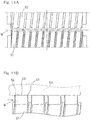
- Fig. 11A illustrates a top plan view of the conventional feed drum assembly
- Fig. 11B illustrates a front elevational view of an important portion of the feed drum assembly.
- a tapered roller which is a workpiece W to be processed
- only an outer diametric straight portion 50 can be used for a process of superfinishing by way of a through feed utilizing feed drums 51 and 52.
- the feed drums 51 and 52 are such that in order to linearly support the workpiece W, the angle of inclination between a grinding stone 53 and the workpiece W is fixed over the entire feed drum region. Accordingly, it is impossible to perform the superfinishing of a crowned portion 54 of the workpiece W with the use of the feed drums 51 and 52.
- a crowned portion of the tapered roller requires a substantial length of processing time and cannot be adapted to a mass production because the superfnishing is performed on the workpiece on a piecemeal basis. Even when the superfinishing of the crowned portion of the tapered roller with the use of a grinding stone having its outer diametric surface shaped to a crowning shape by means of a plunge cutting, the length of processing time required to complete it is indeed substantial and cannot be adapted to a mass production.
- a method of crowning the tapered roller with the use of a centerless grinding machine while an outer diametric surface of the grinding stone and that of a regulating wheel are given a rounded shape cannot be adapted to the shaping of an article to have a radius of curvature of 1,000 mm or smaller and also to the shaping of an article to have a logarithmically curved shape.
- the crowned portion is formed in the tapered roller with the use of the conventional through feed processing method, such limitations have been encountered with that only a single rounded shape and a composite of single rounded shapes.
- a method of processing a crowned portion of a roller comprises a step of disposing first and second feed drums so as to extend parallel to each other, each of the first and second feed drums having an outer periphery formed with respective spirally extending threaded guide surfaces, the first and second feed drums being driven to rotate about respective central axes to transport the roller, while the roller is held in rolling contact with the threaded guide surfaces opposed to each other, from a first location towards a second location through between the first and second feed drums, and successively processing the crowned portion of the roller passing through between the first and second feed drums, by means of a through feed processing with the use of a grinding stone, wherein the threaded guide surface of one of the first and second feed drums is formed so that an angle of inclination of an outer peripheral surface of the roller relative to a processing surface of the grinding stone is varied in dependence on a roller passing position of the feed drunk.
- a primary object of the present invention is to provide a highly versatile processing method, which can be applied in crowning rollers and superfinishing crowned articles, in which not only is the length of processing time reduced, but they can be adapted to the mass production, and which can be used in shaping articles to have a crowned portion of a small radius of curvature and to have a logarithmically curved shape.
- a processing apparatus for processing a crowned portion of a roller which is not part of the claimed subject-matter, includes first and second feed drums each having an outer periphery formed with respective spirally extending threaded guide surfaces, the first and second feed drums extending parallel to each other and being driven to rotate about respective central axes (longitudinal axes) to transport the roller, while the roller is held in rolling contact with the threaded guide surfaces opposed to each other, from a first location towards a second location through between the first and second feed drums; and a grinding stone for processing the crowned portion of the roller passing through between the first and second feed drums.
- the threaded guide surface of one of the first and second feed drums referred to above is divided into two axially juxtaposed divided threaded surface areas so that an outer peripheral surface of the roller may be supported at two anteroposterior locations of such roller.
- the two feed drums are disposed so as to extend parallel to each other and, while the roller is rotated between the feed drums by the rotation of those feed drums, such roller is transported from the upstream side towards the downstream side in the direction of transport. With the grinding stone pressed against the roller then moving between the feed drums, the crowned portion is processed.
- the threaded guide surface of one of the first and second feed drums is so divided into the two axially juxtaposed divided threaded surface areas that the outer peripheral surface of the roller can be supported at the two anteroposterior locations, the difference in radius of curvature can be given to roller contact points on those two divided threaded surface areas and, hence, the roller can be inclined at an arbitrary angle of inclination relative to the grinding stone. Also, since the threaded guide surface is divided into the two axially juxtaposed divided threaded surface areas as hereinabove described, two anteroposterior portions of the outer peripheral surface of the roller can be assuredly supported.
- the crowned portion of the plurality of the rollers can be successively processed by means of the through feed processing with the use of the feed drums and, therefore, as compared with the processing of the rollers on a piecemeal basis or the processing by means of a plunge cutting, the processing can be accomplished in a reduced length of time and the processing apparatus can be advantageously used in a mass production. For this reason, the cost of manufacture of the rollers can be reduced.
- each of the divided threaded surface areas may be of an arcuate shape protruding radially outwardly.
- the roller can be caused to smoothly rollingly contact the divided threaded surface areas each being of an arcuate shape.
- the divided threaded surface areas may be of a type in which the difference between respective radii of curvature at roller contact points of the two axially juxtaposed divided threaded surface areas is varied in dependence on a roller passing position of the feed drums.
- a roller contact point of one of the two axially juxtaposed divided threaded surface areas may be caused to protrude radially outwardly beyond a roller contact point of the other of the two axially juxtaposed divided threaded surface areas such that a surface of the roller guided in contact with those roller contact points is inclined relative to a processing surface of the grinding stone.
- the crowned portion of the roller can be processed with the outer peripheral surface of the roller inclined relative to the processing surface of the grinding stone.
- the angle of inclination of a linear line, which connects between the roller contact points of the two divided threaded surface areas, relative to the central axis of the feed drum may change continuously from an upstream side towards a downstream side with respect to the direction of transport.
- the two divided threaded surface areas are formed, it is possible to change continuously the angle of inclination of the outer peripheral surface of the roller relative to the processing surface of the grinding stone in a direction conforming to the direction of transport. Therefore, for example, it becomes possible to achieve a crowning processing of the roller to have a logarithmically curved shape and, also, a crowning processing of a kind having a minute radius of curvature.
- the threaded guide surface of the feed drum may be divided by spirally extending collared convolutions from the neighboring peripheral portions.
- the roller When in a condition with an end face of the roller held in contact with the collared convolution, the feed drums are rotated, the roller can be transported from an upstream side towards a downstream side in the direction of transport.
- the roller referred to above may be either a cylindrical roller or a tapered roller.
- the present invention provides a method of processing a crowned portion of a roller, which method includes a step of disposing first and second feed drums so as to extend parallel to each other, each of the first and second feed drums having an outer periphery formed with respective spirally extending threaded guide surfaces, the first and second feed drums being driven to rotate about respective central axes to transport the roller, while the roller is held in rolling contact with the threaded guide surfaces opposed to each other, from a first location towards a second location through between the first and second feed drums, and successively processing the crowned portion of the roller passing through between the first and second feed drums, by a grinding stone, wherein the threaded guide surface of one of the first and second feed drums is divided by collared convolutions from neighboring peripheral portions, and the divided threaded guide surface is formed so that an angle of inclination of an outer peripheral surface of the roller relative to a processing surface of the grinding stone is varied in dependence on a roller passing position of the feed drum.
- the threaded guide surface of one of the first and second feed drums is divided into two axially juxtaposed divided threaded surface areas so that an outer peripheral surface of the roller may be supported at two anteroposterior locations of such roller.
- the two feed drums can be disposed so as to extend parallel to each other and, while the roller is rotated between the feed drums by the rotation of those feed drums, such roller is transported from the upstream side towards the downstream side in the direction of transport. With the grinding stone pressed against the roller then moving between the feed drums, the crowned portion is processed.
- the crowned portion of the plurality of the rollers can be successively processed by means of the through feed processing with the use of the feed drums and, therefore, as compared with the processing of the rollers on a piecemeal basis or the processing by means of a plunge cutting, the processing can be accomplished in a reduced length of time and the processing apparatus of the present invention can be advantageously used in a mass production. For this reason, the cost of manufacture of the rollers can be reduced.
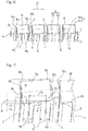
- the processing apparatus mainly includes two feed drums 1 and 2 and a grinding stone 3 best shown in Fig. 4 .
- Each of the two feed drums 1 and 2 has its outer periphery formed with a spirally threaded guide surface 4 and is adapted to be driven about a respective central axis L1 or L2.
- Those two feed drums 1 and 2 are juxtaposed relative to each other with the central axes L1 and L2 extending parallel to each other and are spaced a predetermined distance from each other.
- the processing apparatus referred to above is so designed that a roller W to be processed is passed in between the feed drums 1 and 2 while the roller is held in part in rolling contact with the spirally threaded guide surface 4 of one of the feed drums 1 and 2 and in part in rolling contact with the spirally threaded guide surface 4 of the other of the feed drums 1 and 2.
- the grinding stone 3 referred to above is used to process a crowned portion Wc in the roller W as shown in Fig. 3 .
- the roller W has an outer peripheral surface made up of a straight portion Wd of a linear shape and crowned portions Wc and Wc formed at axially spaced opposite ends of the straight portion Wd.
- Each of the crowned portions Wc best shown in Fig. 3 is of a shape expressed by a logarithmic function and is so formed into the crowned portion Wc of a kind capable of uniformizing the distribution of contact pressures in an axial direction (longitudinal direction).
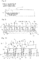
- the plate-like grinding stone 3 is employed in a plural number and those grinding stones 3 are in series with each other in a direction parallel to the respective central axes L1 and L2 of the feed drums 1 and 2 as shown in Fig. 9 with lower edge portions 3a, which are processing surfaces of the grinding stones 3, being inserted in between those feed drums 1 and 2.
- the plurality of those grinding stones 3 are supported by a support member M so that each of the grinding stones 3 can be rocked in a direction parallel to any one of the central axes L1 and L2, best shown in Fig. 4 , relative to the support member M.
- Each of those grinding stones 3 is so structured as to be capable of undergoing a rocking motion (an oscillating motion) in order to form the crowned portions Wc represented by the previously described logarithmic function.
- a gap S is provided between the neighboring grinding stones 3 and 3 so as to avoid an undesirable interference between those neighboring grinding stones 3 and 3 at the time the corresponding grinding stone 3 undergoes the rocking motion.
- Each of the grinding stones 3 rockingly displaces when the rollers W are successively transported in a condition with the crowned portions Wc of the respective roller W contacts the lower end edge portion 3a of the associated grinding stone 3.
- the crowned portion Wc having a minute radius of curvature can be realized when as the respective roller W is transported from an upstream side towards a downstream side with respect to the direction of transport performed by the feed drums 1 and 2, the grinding stone 3 is slightly rockingly displaced in a counterclockwise direction as viewed in Fig. 9 and, at the same time, the roller W is transported with the outer peripheral surface of the roller W inclined relative to the lower edge portion 3a, which is a processing surface of the grinding stone 3.
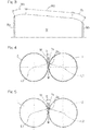
- the two feed drums 1 and 2 are a male side feed drum 1 and a female side feed drum 2.
- the male side feed drum 1 has its threaded guide surface 4 divided by a spirally extending, collared convolutions 5 from neighboring peripheral portions.
- the roller W can be transported from the upstream side towards the downstream side with respect to the direction of transport indicated by the arrow Al with the small end face Wb of the roller W oriented forwards with respect to the direction of transport Al.
- the threaded guide surface 4 referred to above is divided into two divided threaded surface areas 4a and 4b that are axially juxtaposed relative to each other so as to support the outer peripheral surface of the corresponding roller W at two anteroposterior locations.
- a circumferentially extending groove 6 is formed between the axially juxtaposed divided threaded surface areas 4a and 4b that are so divided by the adjacent collared convolutions 5.
- Circumferentially extending grooves 7 and 8 each having a width smaller than the circumferentially extending groove 6 between the divided threaded surface areas 4a and 4b are also formed between each of the divided threaded surface areas 4a and the adjacent collared convolution 5 and between each of the divided threaded surface areas 4b and the adjacent collared convolution 5, respectively.
- the female side feed drum 2 shown in Fig. 1 is not provided with any collared convolutions 5, but the threaded guide surface 4 of such female side feed drum 2 is made up of axially juxtaposed divided threaded surface areas 4a and 4b for supporting the outer peripheral surface of the respective roller W at the two anteroposterior locations.
- each of the divided threaded surface areas 4a and 4b has a predetermined range of the radius of curvature R (for example, 3 to 20 mm in the instance as shown) and has an arcuate shape that protrudes on an outer diametric side, i.e., radially outwardly.
- each of the divided threaded surface areas 4a on the downstream side with respect to the direction of transport of the roller W supports a front side portion of the outer peripheral surface of the roller W whereas each of the divided threaded surface areas 4b on the upstream side with respect to the direction of transport of the roller W supports a rear side portion of the outer peripheral surface of the roller W. Accordingly, in each of the two feed drums 1 and 2, the roller is supported at two points on the divided threaded surface areas 4a and 4b.
- the site of contact of one divided threaded surface area 4a or 4b with the roller W may be a line contact at a minimum region, it is regarded that a point contact takes place at a point intermediate between axial tip and rear ends at the site of contact of the divided threaded surface area 4a or 4b.
- each of the divided threaded surface areas 4a or 4b has an axial dimension Ha or Hb which is so prescribed as to be of the same dimension over the entire direction of transport.
- the top-to-top distance Hc which is the distance between the maximum diametric portions of the neighboring divided threaded surface areas 4a or 4b that are axially juxtaposed relative to each other and divided by the collared convolutions 5, is so prescribed as to be of a constant dimension in dependence on the length of the roller W to be processed.
- a roller contact point of the divided threaded surface area 4a on the downstream side with respect to the direction of transport is rendered to protrude radially outwardly beyond a roller contact point of the divided threaded surface area 4b on the upstream side with respect to the direction of transport, and a linear line Lw connecting between those two roller contact points is rendered to incline relative to the lower end edge portion 3a which is the processing surface of the grinding stone 3.
- the linear line Lw connecting between those two roller contact points represents such a shape as to be inclined upwardly as it goes towards the direction of transport, that is, such a shape as to flare radially outwardly in a direction conforming to the direction of transport of the roller W to be processed.
- the roller contact point of the divided threaded surface area 4b is rendered to protrude radially outwardly beyond the roller contact point of the divided threaded surface area 4a, and the linear line Lw connecting between those two roller contact points is rendered to represent such a shape as to be inclined downwardly as it goes towards the direction of transport, that is, such a shape as to converge radially inwardly in a direction conforming to the direction of transport of the roller W to be processed.
- the divided threaded surface areas 4a and 4b are such that the difference ⁇ between the respective radii of curvature at the roller contact points of the two axially juxtaposed, divided threaded surface areas 4a and 4b is varied depending on a roller passing position of the feed drum 1 or 2.
- the difference ⁇ in radius of curvature is gradually varied from a condition, in which it is set to a large value, to a small value from the upstream side of transport to the vicinity of the intermediate point of transport, but the difference ⁇ in radius of curvature is conversely varied gradually from a condition, in which it is set to a small value, to a large value from the vicinity of the intermediate point of transport to the downstream side of transport.
- the respective roller contact points of the neighboring divided threaded surface areas 4a and 4b of the feed drums 1 and 2 with respect to the direction of transport by the feed drums 1 and 2 are separately varied between the divided threaded surface area 4a on the front side and the divided threaded surface area 4b on the rear side. Accordingly, as shown in Figs. 9 and 10 , relative to the lower end edge portion 3a of the grinding stone 3, which is the processing surface of the grinding stone 3, a surface of the roller W, which is guided in contact with the axially lined two roller contact points, is inclined.
- the angle ⁇ of inclination of the linear line Lw, connecting between the two roller contact points of the two divided threaded surface areas 4a and 4b, relative to the central axis Ll of the feed drum is continuously changed in a direction from the upstream side with respect to the direction of transport of the roller W towards the downstream side thereof.
- a trajectory La ranging from the upstream side towards the downstream side with respect to the direction of transport is shown by the double dotted chain line whereas a trajectory Lb of the roller contact point of the divided threaded surface area 4b on the rear side is shown by the dotted line.
- the divided threaded surface areas 4a and 4b of the feed drums 1 and 2 are so formed that the angle ⁇ of inclination of the linear line Lw, connecting between the two roller contact points relative to the processing surface of the grinding stone 3, relative to the central axis L1 of the feed drum can be varied continuously in the sequence of large ⁇ small ⁇ large in a direction from the upstream side towards the downstream side with respect to the direction of transport of the roller W.
- the crowned portion Wc of the shape represented by the logarithmic function is a crowned portion Wc expressed by the logarithmic function and capable of uniformize an axial distribution of contact pressures.
- the two feed drums 1 and 2 are disposed in a fashion parallel to each other and the roller W between the feed drums 1 and 2 is, while being rotated about its own longitudinal axis by the rotation of the feed drums 1 and 2, transported from the upstream side towards the downstream side with respect to the direction of transport.
- the grinding stone 3 is pressed against the roller W being passed between the feed drums 1 and 2 to thereby process the crowned portions Wc.
- the threaded guide surface 4 of the feed drums 1 and 2 is divided into the axially juxtaposed two divided threaded surface areas 4a and 4b so that the outer peripheral surface of the roller W can be supported at the two anteroposterior locations of the roller W, the difference in radius of curvature can be applied to the two roller contact points of the divided threaded surface areas 4a and 4b and, therefore, the roller W can be inclined at an arbitrarily angle of inclination relative to the grinding stone 3.
- the threaded guide surface 4 is divided into the two axially juxtaposed divided threaded surface areas 4a and 4b, the outer peripheral surface of the roller W can be assuredly supported at the two anteroposterior locations.
- the processing apparatus of the present invention can be suitably applied in a mass production.
- the cost of manufacture of the rollers W can be reduced.
- each of the divided threaded surface areas 4a and 4b is of the arcuate shape protruding radially outwardly, not only can the angle ⁇ of inclination of the linear line Lw, connecting between the two roller contact points, relative to the central axis Ll of the feed drum be set to any desired angle, but also the rollers W can be caused to smoothly contact the divided threaded surface areas 4a and 4b each being of an arcuate shape.
- the divided threaded surface areas 4a and 4b are such that the difference ⁇ between the respective radii of curvature of the two axially juxtaposed divided threaded surface areas 4a and 4b is varied depending on the roller passing position of the feed drums 1 and 2.
- the difference ⁇ between the respective radii of curvature of the two axially juxtaposed divided threaded surface areas 4a and 4b being varied in the manner described above, the angle ⁇ of inclination of the linear line Lw that connects the roller contact points at the two roller contact points can be easily and assuredly changed. Accordingly, the angle of inclination of the outer peripheral surface of the roller W relative to the processing surface of the grinding stone 3 can be easily and assuredly changed.
- the roller W can be transported from the upstream side towards the downstream side in the direction of transport when the feed drums 1 and 2 are rotated while the large end face Wa of the roller W is held in contact with the adjacent collared convolution 5.
- the crowning process it is possible to apply the crowning process to the tapered roller so as to have a single radius of curvature. Also, the process to have a crowned portion free from a straight portion can also be applied to the outer peripheral surface of the tapered roller.
- the difference ⁇ between the respective radii of curvature of the two axially juxtaposed divided threaded surface areas 4a and 4b is chosen in dependence on the various crowned portions as discussed above, the required crowned portion can be easily processed in a length of time shorter than that hitherto required.
- one or some of the grinding stones 3 can be removed from the support member M, best shown in Fig. 9 , for replacement in the event that a biased frictional wear or an earlier frictional wear occur in one or some of the grinding stones 3. Accordingly, the cost for maintenance can be reduced.
- the circumferentially extending grooves 6 are formed between the two axially juxtaposed divided threaded surface areas 4a and 4b in the feed drums 1 and 2, abrasive grains used in processing of the crowned portions Wc can be smoothly discharged to the outside of the feed drums 1 and 2 after they have been temporarily stored within the circumferentially extending grooves 6. Accordingly, since the abrasive grains remaining at locations of contact of the divided threaded surface areas 4a and 4b with the rollers W is minimized, the outer peripheral surface of the roller W can be set to the desired angle ⁇ of inclination. Accordingly, it is possible to process the crowned portions Wc with high accuracy.
- the processing apparatus of the present invention may be used not only in superfinishing the crowned portion of the tapered roller, but also in crowning the tapered roller.
- the workpiece to be processed may not necessarily be limited to the tapered rollers that are used in a tapered roller bearing assembly, but may be any tapered members such as, for example, tapered pins or cylindrical rollers used in a cylindrical roller bearing assembly.
- the two axially juxtaposed divided threaded surface areas may be formed so that the roller having its small end face oriented in a direction conforming to the direction of transport is inclined downwardly with respect to the direction of transport.
- the two axially juxtaposed divided threaded surface portions may be formed so that the roller having its small end face oriented in the direction conforming to the direction of transport is inclined upwardly with respect to the direction of transport.
- the crowned portions Wc of the roller W have been processed with the use of the plurality of the grinding stones 3, the crowned portions at the small end face side and the large end face side of the outer peripheral surface of the roller may be processed by means of the through feed process with the use of only one grinding stone. It is also possible to accomplish the through feed process on the crowned portion by positioning the male side feed drum 1, shown in Fig. 1 , and a feed drum 52 shown in Fig. 11A and having no divided threaded surface area in a fashion parallel to each other.
Landscapes
- Engineering & Computer Science (AREA)
- Mechanical Engineering (AREA)
- General Engineering & Computer Science (AREA)
- Grinding Of Cylindrical And Plane Surfaces (AREA)
- Grinding And Polishing Of Tertiary Curved Surfaces And Surfaces With Complex Shapes (AREA)
- Rolling Contact Bearings (AREA)
- Grinding-Machine Dressing And Accessory Apparatuses (AREA)
Claims (1)
- Procédé de traitement d'une partie convexe (Wc) d'un rouleau (W), lequel procédé comprend une étape :- d'agencement d'un premier et d'un second tambours d'alimentation (1, 2) de manière à ce qu'ils s'étendent parallèlement l'un par rapport à l'autre, chacun du premier et du second tambours d'alimentation (1, 2) ayant une périphérie extérieure formée avec des surfaces de guidage filetées s'étendant en spirale (4), respectives, le premier et le second tambours d'alimentation (1, 2) étant entrainés en rotation sur des axes centraux respectifs (L1, L2) pour transporter le rouleau (W), alors que le rouleau (W) est maintenu en contact de roulement avec les surfaces de guidage filetées (4) opposées les unes aux autres, d'une première position vers une seconde position en passant entre le premier et le second tambours d'alimentation (1, 2), et- de traitement successif de la partie convexe (Wc) du rouleau (W) passant entre le premier et le second tambours d'alimentation (1, 2), au moyen d'un traitement en enfilade à l'aide d'une meule (3) ;dans lequel la surface de guidage filetée (4) de l'un du premier et du second tambours d'alimentation (1, 2) est séparée par des spires en forme de bague (5) de parties périphériques et caractérisé en ce que la surface de guidage filetée séparée (4) est formée de sorte qu'un angle d'inclinaison d'une surface périphérique extérieure du rouleau (W) par rapport à une surface de traitement de la meule (3) varie en fonction de la position de passage d'un rouleau du tambour d'alimentation (1, 2).
Applications Claiming Priority (2)
| Application Number | Priority Date | Filing Date | Title |
|---|---|---|---|
| JP2010208789A JP5602552B2 (ja) | 2010-09-17 | 2010-09-17 | 加工装置 |
| EP11825065.3A EP2617521B1 (fr) | 2010-09-17 | 2011-09-08 | Dispositif et procédé de façonnage |
Related Parent Applications (2)
| Application Number | Title | Priority Date | Filing Date |
|---|---|---|---|
| EP11825065.3A Division-Into EP2617521B1 (fr) | 2010-09-17 | 2011-09-08 | Dispositif et procédé de façonnage |
| EP11825065.3A Division EP2617521B1 (fr) | 2010-09-17 | 2011-09-08 | Dispositif et procédé de façonnage |
Publications (2)
| Publication Number | Publication Date |
|---|---|
| EP3100823A1 EP3100823A1 (fr) | 2016-12-07 |
| EP3100823B1 true EP3100823B1 (fr) | 2018-04-11 |
Family
ID=45831525
Family Applications (2)
| Application Number | Title | Priority Date | Filing Date |
|---|---|---|---|
| EP11825065.3A Not-in-force EP2617521B1 (fr) | 2010-09-17 | 2011-09-08 | Dispositif et procédé de façonnage |
| EP16169935.0A Not-in-force EP3100823B1 (fr) | 2010-09-17 | 2011-09-08 | Procédé de traitement |
Family Applications Before (1)
| Application Number | Title | Priority Date | Filing Date |
|---|---|---|---|
| EP11825065.3A Not-in-force EP2617521B1 (fr) | 2010-09-17 | 2011-09-08 | Dispositif et procédé de façonnage |
Country Status (5)
| Country | Link |
|---|---|
| US (2) | US9446492B2 (fr) |
| EP (2) | EP2617521B1 (fr) |
| JP (1) | JP5602552B2 (fr) |
| CN (1) | CN103108724B (fr) |
| WO (1) | WO2012036062A1 (fr) |
Cited By (2)
| Publication number | Priority date | Publication date | Assignee | Title |
|---|---|---|---|---|
| DE102019135530A1 (de) * | 2019-12-20 | 2021-06-24 | Supfina Grieshaber Gmbh & Co. Kg | Vorrichtung zur Finishbearbeitung von Wälzkörpern |
| DE102020114006A1 (de) | 2020-05-26 | 2021-12-02 | Schaeffler Technologies AG & Co. KG | Vorrichtung und Verfahren zum Honen von Tonnenrollen |
Families Citing this family (11)
| Publication number | Priority date | Publication date | Assignee | Title |
|---|---|---|---|---|
| JP5920044B2 (ja) * | 2012-06-18 | 2016-05-18 | 株式会社ジェイテクト | 円錐ころ組付け装置 |
| CN102878206B (zh) * | 2012-08-22 | 2015-04-22 | 宁夏勤昌滚动轴承制造有限公司 | 母线分段对称凸度圆锥滚子及终磨方法 |
| CN103465149B (zh) * | 2013-05-16 | 2015-09-09 | 河南科技大学 | 小端抬高贯穿式圆锥滚子凸度超精研方法 |
| CN103394978B (zh) * | 2013-07-18 | 2016-01-13 | 蒿庆国 | 一种圆锥滚子无心磨床 |
| JP6519227B2 (ja) * | 2015-02-26 | 2019-05-29 | 株式会社ジェイテクト | 加工装置 |
| JP2017094404A (ja) * | 2015-11-18 | 2017-06-01 | Ntn株式会社 | 軸受用ころの超仕上げ加工方法および超仕上げ加工装置 |
| JP6719935B2 (ja) * | 2016-03-18 | 2020-07-08 | Ntn株式会社 | 円すいころ軸受 |
| US11143235B2 (en) | 2016-03-18 | 2021-10-12 | Ntn Corporation | Tapered roller bearing |
| JP6739968B2 (ja) * | 2016-04-01 | 2020-08-12 | Ntn株式会社 | 円すいころ軸受 |
| CN105798712B (zh) * | 2016-05-24 | 2018-02-16 | 洛阳宜华滚动体有限公司 | 一种加工圆锥滚子的软磨工艺及设备 |
| CN110871395A (zh) * | 2019-12-03 | 2020-03-10 | 中南大学 | 一种圆锥滚子轴承的滚子超精加工新设备 |
Family Cites Families (25)
| Publication number | Priority date | Publication date | Assignee | Title |
|---|---|---|---|---|
| US2043972A (en) * | 1925-03-02 | 1936-06-09 | Motch Merryweather Machinery | Centerless grinding machinery |
| US1767775A (en) * | 1927-08-19 | 1930-06-24 | Jr Edwin E Slick | Grinding machine and method of grinding |
| US1886579A (en) * | 1930-08-12 | 1932-11-08 | Hoover Steel Ball Company | Grinding machine |
| US2002489A (en) * | 1931-07-03 | 1935-05-28 | Cincinnati Grinders Inc | Grinding machine |
| US2132280A (en) * | 1933-07-03 | 1938-10-04 | Bower Roller Bearing Co | Method and means for grinding tapered rolls |
| US2476683A (en) * | 1948-04-17 | 1949-07-19 | Pieri Gino | Polishing apparatus |
| CS176452B1 (fr) * | 1973-08-28 | 1977-06-30 | ||
| JPS6021170B2 (ja) | 1976-09-27 | 1985-05-25 | 株式会社東芝 | 熱硬化性樹脂組成物 |
| JPS6021170Y2 (ja) * | 1980-02-14 | 1985-06-24 | 日本精工株式会社 | 円とうころの超仕上クラウニング加工用通し送りねじロ−ル装置 |
| JPS56121562A (en) | 1980-02-28 | 1981-09-24 | Mitsubishi Electric Corp | Irradiation controller |
| JPS5930653B2 (ja) | 1981-05-13 | 1984-07-28 | 株式会社東芝 | マイクロ波加熱脱硝装置 |
| DE3225977A1 (de) * | 1982-07-10 | 1984-01-12 | Supfina Maschinenfabrik Hentzen GmbH & Co KG, 5630 Remscheid | Verfahren und vorrichtung zur feinstbearbeitung konvexer oder konkaver mantelflaechen rotationssymmetrischer werkstuecke, insbesondere von waelzlagerrollen |
| JPS5930653A (ja) * | 1982-08-04 | 1984-02-18 | Koyo Seiko Co Ltd | 円筒ころの製造方法 |
| JPS6021170A (ja) | 1983-07-15 | 1985-02-02 | Nisshin Steel Co Ltd | 連続鋳造用ノズル |
| JPH07100743A (ja) * | 1993-09-30 | 1995-04-18 | Ntn Corp | 円筒部品の研削装置 |
| JPH07290347A (ja) * | 1994-04-21 | 1995-11-07 | Ngk Spark Plug Co Ltd | クラウニング形状物の製造方法と心なし研削盤 |
| DE4425561C2 (de) * | 1994-07-20 | 1997-02-06 | Supfina Maschf Hentzen | Verfahren und Vorrichtung zum spitzenlosen Kurzhubhonen von Rollen |
| DE19543941C1 (de) * | 1995-11-25 | 1996-10-31 | Skf Gmbh | Vorrichtung zum Honen von Kegelrollen |
| JP2003340692A (ja) * | 2002-05-20 | 2003-12-02 | Denso Corp | クラウニング形状を有するローラの製造装置 |
| JP2004322307A (ja) | 2003-04-09 | 2004-11-18 | Nsk Ltd | 超仕上げ加工装置、超仕上げ加工方法、転動体及び転がり軸受 |
| JP4986558B2 (ja) * | 2006-09-20 | 2012-07-25 | Ntn株式会社 | ねじ状クラウニングドラム形状測定方法 |
| JP5142875B2 (ja) * | 2008-07-30 | 2013-02-13 | Ntn株式会社 | センタレス研削用調整車ドラム |
| CN101367179B (zh) * | 2008-10-16 | 2011-05-11 | 濮阳贝英数控机械设备有限公司 | 圆锥滚子无心磨床及其工作方法 |
| CN101433984B (zh) * | 2008-12-12 | 2011-01-05 | 周良财 | 无心滚珠丝杠磨床及其磨削加工工艺 |
| CN101767297B (zh) * | 2010-03-04 | 2011-07-20 | 濮阳贝英数控机械设备有限公司 | 圆锥滚子无心磨床防倒置进料装置及使用方法 |
-
2010
- 2010-09-17 JP JP2010208789A patent/JP5602552B2/ja not_active Expired - Fee Related
-
2011
- 2011-09-08 EP EP11825065.3A patent/EP2617521B1/fr not_active Not-in-force
- 2011-09-08 US US13/822,370 patent/US9446492B2/en not_active Expired - Fee Related
- 2011-09-08 EP EP16169935.0A patent/EP3100823B1/fr not_active Not-in-force
- 2011-09-08 WO PCT/JP2011/070458 patent/WO2012036062A1/fr active Application Filing
- 2011-09-08 CN CN201180044464.7A patent/CN103108724B/zh not_active Expired - Fee Related
-
2015
- 2015-11-05 US US14/933,242 patent/US9700984B2/en not_active Expired - Fee Related
Non-Patent Citations (1)
| Title |
|---|
| None * |
Cited By (3)
| Publication number | Priority date | Publication date | Assignee | Title |
|---|---|---|---|---|
| DE102019135530A1 (de) * | 2019-12-20 | 2021-06-24 | Supfina Grieshaber Gmbh & Co. Kg | Vorrichtung zur Finishbearbeitung von Wälzkörpern |
| DE102020114006A1 (de) | 2020-05-26 | 2021-12-02 | Schaeffler Technologies AG & Co. KG | Vorrichtung und Verfahren zum Honen von Tonnenrollen |
| WO2021239182A1 (fr) | 2020-05-26 | 2021-12-02 | Schaeffler Technologies AG & Co. KG | Dispositif et procédé de rodage à la pierre de rouleaux cylindriques |
Also Published As
| Publication number | Publication date |
|---|---|
| JP2012061571A (ja) | 2012-03-29 |
| US9446492B2 (en) | 2016-09-20 |
| US20160052100A1 (en) | 2016-02-25 |
| CN103108724A (zh) | 2013-05-15 |
| JP5602552B2 (ja) | 2014-10-08 |
| CN103108724B (zh) | 2015-06-03 |
| WO2012036062A1 (fr) | 2012-03-22 |
| EP2617521A4 (fr) | 2018-01-24 |
| EP2617521A1 (fr) | 2013-07-24 |
| US20130171914A1 (en) | 2013-07-04 |
| US9700984B2 (en) | 2017-07-11 |
| EP2617521B1 (fr) | 2019-07-31 |
| EP3100823A1 (fr) | 2016-12-07 |
Similar Documents
| Publication | Publication Date | Title |
|---|---|---|
| EP3100823B1 (fr) | Procédé de traitement | |
| WO2017086120A1 (fr) | Procédé et dispositif pour superfinir un rouleau de palier | |
| EP1035339B2 (fr) | Palier à rouleaux et une méthode pour sa production | |
| US20050265644A1 (en) | Split outer race, split rolling bearing using same, and manufacturing method for split outer race | |
| EP2378147B1 (fr) | Elément de machine et procédé de superfinissage associé | |
| CN101903130A (zh) | 用于切割部件的按压装置、以及用于抛光圆柱形工件部分的周面的设备和方法 | |
| JP5842550B2 (ja) | 超仕上げ加工装置、超仕上げ加工方法、及び外輪の製造方法 | |
| US20040264825A1 (en) | Superfinishing machine, superfinishing method, rolling element and rolling bearing | |
| CN105041875B (zh) | 滚子轴承用套圈、滚子轴承及动力传递装置 | |
| JP5239589B2 (ja) | 研削加工装置、及び研削加工方法 | |
| JP2009275842A (ja) | 外輪の軌道面の加工方法及び車輪用転がり軸受装置の外輪の製造方法 | |
| JP2009041757A (ja) | 金属製保持器の製造方法 | |
| JP2009233732A (ja) | 軸方向断面の表面形状が複雑なリング状製品のリングローリング方法 | |
| JP4923369B2 (ja) | センタレス研削盤 | |
| EP1666746B1 (fr) | Roulement a rouleaux d'auto-alignement et procede de traitement associe | |
| JP2015031343A (ja) | ころ軸受及びころ軸受の製造方法 | |
| WO2014010629A1 (fr) | Joint homocinétique du type tripode et son procédé de fabrication | |
| JP2010266057A (ja) | 両頭円すいころ式、転がり軸受 | |
| CN109804178A (zh) | 环的制造方法以及环的研磨装置 | |
| WO2023238364A1 (fr) | Procédé de fabrication de rouleaux pour paliers | |
| RU2207943C2 (ru) | Способ безабразивной обработки дорожек качения подшипников и устройство для его осуществления | |
| RU2264904C2 (ru) | Способ двусторонней финишной обработки торцов цилиндрических деталей | |
| JP6409474B2 (ja) | 砥石、砥石面形状の決定方法、及び、砥石の製造方法 | |
| JP2007321892A (ja) | 環状部品の製造方法 | |
| JP2001027258A (ja) | ユニバーサルジョイントのカップ |
Legal Events
| Date | Code | Title | Description |
|---|---|---|---|
| PUAI | Public reference made under article 153(3) epc to a published international application that has entered the european phase |
Free format text: ORIGINAL CODE: 0009012 |
|
| STAA | Information on the status of an ep patent application or granted ep patent |
Free format text: STATUS: THE APPLICATION HAS BEEN PUBLISHED |
|
| AC | Divisional application: reference to earlier application |
Ref document number: 2617521 Country of ref document: EP Kind code of ref document: P |
|
| AK | Designated contracting states |
Kind code of ref document: A1 Designated state(s): AL AT BE BG CH CY CZ DE DK EE ES FI FR GB GR HR HU IE IS IT LI LT LU LV MC MK MT NL NO PL PT RO RS SE SI SK SM TR |
|
| STAA | Information on the status of an ep patent application or granted ep patent |
Free format text: STATUS: REQUEST FOR EXAMINATION WAS MADE |
|
| 17P | Request for examination filed |
Effective date: 20170606 |
|
| RBV | Designated contracting states (corrected) |
Designated state(s): AL AT BE BG CH CY CZ DE DK EE ES FI FR GB GR HR HU IE IS IT LI LT LU LV MC MK MT NL NO PL PT RO RS SE SI SK SM TR |
|
| GRAP | Despatch of communication of intention to grant a patent |
Free format text: ORIGINAL CODE: EPIDOSNIGR1 |
|
| STAA | Information on the status of an ep patent application or granted ep patent |
Free format text: STATUS: GRANT OF PATENT IS INTENDED |
|
| INTG | Intention to grant announced |
Effective date: 20171020 |
|
| GRAS | Grant fee paid |
Free format text: ORIGINAL CODE: EPIDOSNIGR3 |
|
| GRAA | (expected) grant |
Free format text: ORIGINAL CODE: 0009210 |
|
| STAA | Information on the status of an ep patent application or granted ep patent |
Free format text: STATUS: THE PATENT HAS BEEN GRANTED |
|
| AC | Divisional application: reference to earlier application |
Ref document number: 2617521 Country of ref document: EP Kind code of ref document: P |
|
| AK | Designated contracting states |
Kind code of ref document: B1 Designated state(s): AL AT BE BG CH CY CZ DE DK EE ES FI FR GB GR HR HU IE IS IT LI LT LU LV MC MK MT NL NO PL PT RO RS SE SI SK SM TR |
|
| REG | Reference to a national code |
Ref country code: GB Ref legal event code: FG4D |
|
| REG | Reference to a national code |
Ref country code: CH Ref legal event code: EP |
|
| REG | Reference to a national code |
Ref country code: AT Ref legal event code: REF Ref document number: 987484 Country of ref document: AT Kind code of ref document: T Effective date: 20180415 |
|
| REG | Reference to a national code |
Ref country code: IE Ref legal event code: FG4D |
|
| REG | Reference to a national code |
Ref country code: DE Ref legal event code: R096 Ref document number: 602011047515 Country of ref document: DE |
|
| REG | Reference to a national code |
Ref country code: FR Ref legal event code: PLFP Year of fee payment: 8 |
|
| REG | Reference to a national code |
Ref country code: NL Ref legal event code: MP Effective date: 20180411 |
|
| REG | Reference to a national code |
Ref country code: LT Ref legal event code: MG4D |
|
| PG25 | Lapsed in a contracting state [announced via postgrant information from national office to epo] |
Ref country code: NL Free format text: LAPSE BECAUSE OF FAILURE TO SUBMIT A TRANSLATION OF THE DESCRIPTION OR TO PAY THE FEE WITHIN THE PRESCRIBED TIME-LIMIT Effective date: 20180411 |
|
| PG25 | Lapsed in a contracting state [announced via postgrant information from national office to epo] |
Ref country code: LT Free format text: LAPSE BECAUSE OF FAILURE TO SUBMIT A TRANSLATION OF THE DESCRIPTION OR TO PAY THE FEE WITHIN THE PRESCRIBED TIME-LIMIT Effective date: 20180411 Ref country code: PL Free format text: LAPSE BECAUSE OF FAILURE TO SUBMIT A TRANSLATION OF THE DESCRIPTION OR TO PAY THE FEE WITHIN THE PRESCRIBED TIME-LIMIT Effective date: 20180411 Ref country code: ES Free format text: LAPSE BECAUSE OF FAILURE TO SUBMIT A TRANSLATION OF THE DESCRIPTION OR TO PAY THE FEE WITHIN THE PRESCRIBED TIME-LIMIT Effective date: 20180411 Ref country code: PT Free format text: LAPSE BECAUSE OF FAILURE TO SUBMIT A TRANSLATION OF THE DESCRIPTION OR TO PAY THE FEE WITHIN THE PRESCRIBED TIME-LIMIT Effective date: 20180813 Ref country code: NO Free format text: LAPSE BECAUSE OF FAILURE TO SUBMIT A TRANSLATION OF THE DESCRIPTION OR TO PAY THE FEE WITHIN THE PRESCRIBED TIME-LIMIT Effective date: 20180711 Ref country code: FI Free format text: LAPSE BECAUSE OF FAILURE TO SUBMIT A TRANSLATION OF THE DESCRIPTION OR TO PAY THE FEE WITHIN THE PRESCRIBED TIME-LIMIT Effective date: 20180411 Ref country code: BG Free format text: LAPSE BECAUSE OF FAILURE TO SUBMIT A TRANSLATION OF THE DESCRIPTION OR TO PAY THE FEE WITHIN THE PRESCRIBED TIME-LIMIT Effective date: 20180711 Ref country code: SE Free format text: LAPSE BECAUSE OF FAILURE TO SUBMIT A TRANSLATION OF THE DESCRIPTION OR TO PAY THE FEE WITHIN THE PRESCRIBED TIME-LIMIT Effective date: 20180411 Ref country code: AL Free format text: LAPSE BECAUSE OF FAILURE TO SUBMIT A TRANSLATION OF THE DESCRIPTION OR TO PAY THE FEE WITHIN THE PRESCRIBED TIME-LIMIT Effective date: 20180411 |
|
| PG25 | Lapsed in a contracting state [announced via postgrant information from national office to epo] |
Ref country code: LV Free format text: LAPSE BECAUSE OF FAILURE TO SUBMIT A TRANSLATION OF THE DESCRIPTION OR TO PAY THE FEE WITHIN THE PRESCRIBED TIME-LIMIT Effective date: 20180411 Ref country code: RS Free format text: LAPSE BECAUSE OF FAILURE TO SUBMIT A TRANSLATION OF THE DESCRIPTION OR TO PAY THE FEE WITHIN THE PRESCRIBED TIME-LIMIT Effective date: 20180411 Ref country code: GR Free format text: LAPSE BECAUSE OF FAILURE TO SUBMIT A TRANSLATION OF THE DESCRIPTION OR TO PAY THE FEE WITHIN THE PRESCRIBED TIME-LIMIT Effective date: 20180712 Ref country code: HR Free format text: LAPSE BECAUSE OF FAILURE TO SUBMIT A TRANSLATION OF THE DESCRIPTION OR TO PAY THE FEE WITHIN THE PRESCRIBED TIME-LIMIT Effective date: 20180411 |
|
| REG | Reference to a national code |
Ref country code: AT Ref legal event code: MK05 Ref document number: 987484 Country of ref document: AT Kind code of ref document: T Effective date: 20180411 |
|
| REG | Reference to a national code |
Ref country code: DE Ref legal event code: R097 Ref document number: 602011047515 Country of ref document: DE |
|
| PG25 | Lapsed in a contracting state [announced via postgrant information from national office to epo] |
Ref country code: SK Free format text: LAPSE BECAUSE OF FAILURE TO SUBMIT A TRANSLATION OF THE DESCRIPTION OR TO PAY THE FEE WITHIN THE PRESCRIBED TIME-LIMIT Effective date: 20180411 Ref country code: RO Free format text: LAPSE BECAUSE OF FAILURE TO SUBMIT A TRANSLATION OF THE DESCRIPTION OR TO PAY THE FEE WITHIN THE PRESCRIBED TIME-LIMIT Effective date: 20180411 Ref country code: CZ Free format text: LAPSE BECAUSE OF FAILURE TO SUBMIT A TRANSLATION OF THE DESCRIPTION OR TO PAY THE FEE WITHIN THE PRESCRIBED TIME-LIMIT Effective date: 20180411 Ref country code: DK Free format text: LAPSE BECAUSE OF FAILURE TO SUBMIT A TRANSLATION OF THE DESCRIPTION OR TO PAY THE FEE WITHIN THE PRESCRIBED TIME-LIMIT Effective date: 20180411 Ref country code: AT Free format text: LAPSE BECAUSE OF FAILURE TO SUBMIT A TRANSLATION OF THE DESCRIPTION OR TO PAY THE FEE WITHIN THE PRESCRIBED TIME-LIMIT Effective date: 20180411 Ref country code: EE Free format text: LAPSE BECAUSE OF FAILURE TO SUBMIT A TRANSLATION OF THE DESCRIPTION OR TO PAY THE FEE WITHIN THE PRESCRIBED TIME-LIMIT Effective date: 20180411 |
|
| PLBE | No opposition filed within time limit |
Free format text: ORIGINAL CODE: 0009261 |
|
| STAA | Information on the status of an ep patent application or granted ep patent |
Free format text: STATUS: NO OPPOSITION FILED WITHIN TIME LIMIT |
|
| PG25 | Lapsed in a contracting state [announced via postgrant information from national office to epo] |
Ref country code: SM Free format text: LAPSE BECAUSE OF FAILURE TO SUBMIT A TRANSLATION OF THE DESCRIPTION OR TO PAY THE FEE WITHIN THE PRESCRIBED TIME-LIMIT Effective date: 20180411 Ref country code: IT Free format text: LAPSE BECAUSE OF FAILURE TO SUBMIT A TRANSLATION OF THE DESCRIPTION OR TO PAY THE FEE WITHIN THE PRESCRIBED TIME-LIMIT Effective date: 20180411 |
|
| 26N | No opposition filed |
Effective date: 20190114 |
|
| PG25 | Lapsed in a contracting state [announced via postgrant information from national office to epo] |
Ref country code: MC Free format text: LAPSE BECAUSE OF FAILURE TO SUBMIT A TRANSLATION OF THE DESCRIPTION OR TO PAY THE FEE WITHIN THE PRESCRIBED TIME-LIMIT Effective date: 20180411 |
|
| REG | Reference to a national code |
Ref country code: CH Ref legal event code: PL |
|
| PG25 | Lapsed in a contracting state [announced via postgrant information from national office to epo] |
Ref country code: SI Free format text: LAPSE BECAUSE OF FAILURE TO SUBMIT A TRANSLATION OF THE DESCRIPTION OR TO PAY THE FEE WITHIN THE PRESCRIBED TIME-LIMIT Effective date: 20180411 |
|
| REG | Reference to a national code |
Ref country code: BE Ref legal event code: MM Effective date: 20180930 |
|
| REG | Reference to a national code |
Ref country code: IE Ref legal event code: MM4A |
|
| PG25 | Lapsed in a contracting state [announced via postgrant information from national office to epo] |
Ref country code: LU Free format text: LAPSE BECAUSE OF NON-PAYMENT OF DUE FEES Effective date: 20180908 |
|
| PG25 | Lapsed in a contracting state [announced via postgrant information from national office to epo] |
Ref country code: IE Free format text: LAPSE BECAUSE OF NON-PAYMENT OF DUE FEES Effective date: 20180908 |
|
| PG25 | Lapsed in a contracting state [announced via postgrant information from national office to epo] |
Ref country code: LI Free format text: LAPSE BECAUSE OF NON-PAYMENT OF DUE FEES Effective date: 20180930 Ref country code: BE Free format text: LAPSE BECAUSE OF NON-PAYMENT OF DUE FEES Effective date: 20180930 Ref country code: CH Free format text: LAPSE BECAUSE OF NON-PAYMENT OF DUE FEES Effective date: 20180930 |
|
| PGFP | Annual fee paid to national office [announced via postgrant information from national office to epo] |
Ref country code: FR Payment date: 20190815 Year of fee payment: 9 Ref country code: DE Payment date: 20190827 Year of fee payment: 9 |
|
| PGFP | Annual fee paid to national office [announced via postgrant information from national office to epo] |
Ref country code: GB Payment date: 20190905 Year of fee payment: 9 |
|
| PG25 | Lapsed in a contracting state [announced via postgrant information from national office to epo] |
Ref country code: MT Free format text: LAPSE BECAUSE OF NON-PAYMENT OF DUE FEES Effective date: 20180908 |
|
| PG25 | Lapsed in a contracting state [announced via postgrant information from national office to epo] |
Ref country code: TR Free format text: LAPSE BECAUSE OF FAILURE TO SUBMIT A TRANSLATION OF THE DESCRIPTION OR TO PAY THE FEE WITHIN THE PRESCRIBED TIME-LIMIT Effective date: 20180411 |
|
| PG25 | Lapsed in a contracting state [announced via postgrant information from national office to epo] |
Ref country code: CY Free format text: LAPSE BECAUSE OF FAILURE TO SUBMIT A TRANSLATION OF THE DESCRIPTION OR TO PAY THE FEE WITHIN THE PRESCRIBED TIME-LIMIT Effective date: 20180411 Ref country code: HU Free format text: LAPSE BECAUSE OF FAILURE TO SUBMIT A TRANSLATION OF THE DESCRIPTION OR TO PAY THE FEE WITHIN THE PRESCRIBED TIME-LIMIT; INVALID AB INITIO Effective date: 20110908 Ref country code: MK Free format text: LAPSE BECAUSE OF NON-PAYMENT OF DUE FEES Effective date: 20180411 |
|
| PG25 | Lapsed in a contracting state [announced via postgrant information from national office to epo] |
Ref country code: IS Free format text: LAPSE BECAUSE OF FAILURE TO SUBMIT A TRANSLATION OF THE DESCRIPTION OR TO PAY THE FEE WITHIN THE PRESCRIBED TIME-LIMIT Effective date: 20180811 |
|
| REG | Reference to a national code |
Ref country code: DE Ref legal event code: R119 Ref document number: 602011047515 Country of ref document: DE |
|
| GBPC | Gb: european patent ceased through non-payment of renewal fee |
Effective date: 20200908 |
|
| PG25 | Lapsed in a contracting state [announced via postgrant information from national office to epo] |
Ref country code: FR Free format text: LAPSE BECAUSE OF NON-PAYMENT OF DUE FEES Effective date: 20200930 Ref country code: DE Free format text: LAPSE BECAUSE OF NON-PAYMENT OF DUE FEES Effective date: 20210401 |
|
| PG25 | Lapsed in a contracting state [announced via postgrant information from national office to epo] |
Ref country code: GB Free format text: LAPSE BECAUSE OF NON-PAYMENT OF DUE FEES Effective date: 20200908 |