WO2012036062A1 - Dispositif et procédé de façonnage - Google Patents
Dispositif et procédé de façonnage Download PDFInfo
- Publication number
- WO2012036062A1 WO2012036062A1 PCT/JP2011/070458 JP2011070458W WO2012036062A1 WO 2012036062 A1 WO2012036062 A1 WO 2012036062A1 JP 2011070458 W JP2011070458 W JP 2011070458W WO 2012036062 A1 WO2012036062 A1 WO 2012036062A1
- Authority
- WO
- WIPO (PCT)
- Prior art keywords
- roller
- processing
- feed
- crowning
- screw surface
- Prior art date
Links
Images


Classifications
-
- B—PERFORMING OPERATIONS; TRANSPORTING
- B24—GRINDING; POLISHING
- B24B—MACHINES, DEVICES, OR PROCESSES FOR GRINDING OR POLISHING; DRESSING OR CONDITIONING OF ABRADING SURFACES; FEEDING OF GRINDING, POLISHING, OR LAPPING AGENTS
- B24B5/00—Machines or devices designed for grinding surfaces of revolution on work, including those which also grind adjacent plane surfaces; Accessories therefor
- B24B5/02—Machines or devices designed for grinding surfaces of revolution on work, including those which also grind adjacent plane surfaces; Accessories therefor involving centres or chucks for holding work
- B24B5/04—Machines or devices designed for grinding surfaces of revolution on work, including those which also grind adjacent plane surfaces; Accessories therefor involving centres or chucks for holding work for grinding cylindrical surfaces externally
-
- B—PERFORMING OPERATIONS; TRANSPORTING
- B24—GRINDING; POLISHING
- B24B—MACHINES, DEVICES, OR PROCESSES FOR GRINDING OR POLISHING; DRESSING OR CONDITIONING OF ABRADING SURFACES; FEEDING OF GRINDING, POLISHING, OR LAPPING AGENTS
- B24B19/00—Single-purpose machines or devices for particular grinding operations not covered by any other main group
- B24B19/02—Single-purpose machines or devices for particular grinding operations not covered by any other main group for grinding grooves, e.g. on shafts, in casings, in tubes, homokinetic joint elements
- B24B19/06—Single-purpose machines or devices for particular grinding operations not covered by any other main group for grinding grooves, e.g. on shafts, in casings, in tubes, homokinetic joint elements for grinding races, e.g. roller races
-
- B—PERFORMING OPERATIONS; TRANSPORTING
- B24—GRINDING; POLISHING
- B24B—MACHINES, DEVICES, OR PROCESSES FOR GRINDING OR POLISHING; DRESSING OR CONDITIONING OF ABRADING SURFACES; FEEDING OF GRINDING, POLISHING, OR LAPPING AGENTS
- B24B5/00—Machines or devices designed for grinding surfaces of revolution on work, including those which also grind adjacent plane surfaces; Accessories therefor
- B24B5/18—Machines or devices designed for grinding surfaces of revolution on work, including those which also grind adjacent plane surfaces; Accessories therefor involving centreless means for supporting, guiding, floating or rotating work
- B24B5/24—Machines or devices designed for grinding surfaces of revolution on work, including those which also grind adjacent plane surfaces; Accessories therefor involving centreless means for supporting, guiding, floating or rotating work for grinding conical surfaces
- B24B5/245—Machines or devices designed for grinding surfaces of revolution on work, including those which also grind adjacent plane surfaces; Accessories therefor involving centreless means for supporting, guiding, floating or rotating work for grinding conical surfaces for mass articles
-
- F—MECHANICAL ENGINEERING; LIGHTING; HEATING; WEAPONS; BLASTING
- F16—ENGINEERING ELEMENTS AND UNITS; GENERAL MEASURES FOR PRODUCING AND MAINTAINING EFFECTIVE FUNCTIONING OF MACHINES OR INSTALLATIONS; THERMAL INSULATION IN GENERAL
- F16C—SHAFTS; FLEXIBLE SHAFTS; ELEMENTS OR CRANKSHAFT MECHANISMS; ROTARY BODIES OTHER THAN GEARING ELEMENTS; BEARINGS
- F16C33/00—Parts of bearings; Special methods for making bearings or parts thereof
- F16C33/30—Parts of ball or roller bearings
- F16C33/34—Rollers; Needles
- F16C33/36—Rollers; Needles with bearing-surfaces other than cylindrical, e.g. tapered; with grooves in the bearing surfaces
- F16C33/366—Tapered rollers, i.e. rollers generally shaped as truncated cones
Definitions
- the present invention relates to a processing apparatus and a processing method applied to crowning processing and crowning superfinishing processing of cylindrical rollers and tapered rollers.
- FIG. 11 (A) is a plan view of a conventional feed drum
- FIG. 11 (B) is a front view of the main part of the feed drum.
- a tapered roller which is a workpiece W can be subjected to through-feed super finishing using only the outer diameter straight portion 50 using the feed drums 51 and 52 (Patent Document 1).
- the feed drums 51 and 52 linearly support the work W, the inclination angle of the grindstone 53 and the work W is constant throughout the feed drum. Therefore, it is impossible to superfinish the crowning portion 54 of the workpiece W using the feed drums 51 and 52.
- the object of the present invention is applied to roller crowning and crowning super-finishing, which can reduce machining time, can be applied to mass production, and can cope with crowning with a small curvature, logarithmic curve shape, etc. It is to provide a versatile processing apparatus and processing method that can be used.
- the processing device is a processing device for processing a crowning portion of a roller, and has two guide drums each having a spiral guide screw surface on the outer periphery and driven to rotate about a central axis in parallel. These feed drums are made by rolling the rollers on the guide screw surfaces facing each other and passing the rollers between the two feed drums by rotation, and processing the crowning portion of the rollers passing between the feed drums. Two divided screw face portions arranged in the axial direction so that the guide screw face of either one of the two feed drums supports the outer peripheral face of the roller at two positions on the front and rear sides of the same roller. It is divided into
- two feed drums are installed in parallel, and the rollers between the feed drums are conveyed from the upstream side to the downstream side in the conveyance direction while rotating by the rotation of the feed drum.
- the crown is pressed by pressing a grindstone while passing between the feed drums.
- the guide screw surface of any one of the feed drums is divided into two divided screw surface portions arranged in the axial direction so as to support the outer peripheral surface of the roller at two positions on the front and rear sides of the roller.
- a radius difference can be given to the roller contact point of the thread surface portion, and the roller can be inclined at an arbitrary inclination angle with respect to the grindstone.
- the guide screw surface is divided into two divided screw surface portions arranged in the axial direction, the two front and rear portions of the outer peripheral surface of the roller can be reliably supported. Therefore, the crowning part of multiple rollers can be processed sequentially by through-feed machining using a feed drum, so the machining time is shortened compared to machining the crowning parts of rollers one by one or by plunge cutting.
- the present processing apparatus can be applied to mass production. Therefore, it is possible to reduce the manufacturing cost of the rollers.
- each divided screw surface portion may have an arc shape that is convex toward the outer diameter side.
- the outer peripheral surface of the roller can be reliably set to a desired inclination angle with respect to the processing surface of the grindstone, and the roller can be smoothly brought into rolling contact with the divided screw surface portion having an arc shape.
- the thread surface portion may be configured such that a radial difference between roller contact points of two divided thread surface portions arranged in the axial direction is changed depending on a roller passing position of the feed drum. In this way, by changing the radius difference between the roller contact points of the two divided screw surface portions arranged in the axial direction, the inclination angle of the outer peripheral surface of the roller with respect to the processing surface of the grindstone can be easily and reliably changed.
- the roller contact point of either one of the two divided screw surface portions aligned in the axial direction protrude in the radial direction from the roller contact point of the other divided screw surface portion the roller contact of these two points You may make it incline the surface of the roller guided in contact with a point with respect to the processing surface of the said grindstone.
- the crowning portion of the roller can be processed by inclining the outer peripheral surface of the roller with respect to the processing surface of the grindstone.
- the inclination angle of the straight line connecting the two roller contact points of the two split screw surface portions with respect to the feed drum axis is continuously changed from the upstream side toward the downstream side in the roller conveying direction. It may be.
- the inclination angle of the outer peripheral surface of the roller with respect to the processing surface of the grindstone can be continuously changed along the conveying direction. Therefore, for example, a logarithmic curve shape crowning process or a crowning process with a small curvature can be performed on the rollers.
- the guide screw surface of the feed drum may be separated from the adjacent peripheral surface portion by a spiral flange.
- the roller can be transported from the upstream side in the transport direction to the downstream side by rotating the feed drum with the end face of the roller in contact with the flange.
- the roller may be a cylindrical roller or a tapered roller.
- the processing method of the present invention is a processing method for processing a crowning portion of a roller, and has two guide drums that have a guide screw surface that follows a spiral shape on the outer periphery and are driven to rotate about a central axis in parallel.
- These feed drums are configured such that rollers are brought into contact with guide screw surfaces facing each other, the rollers are passed between both feed drums by rotation, and a crowning portion of the rollers passing between the feed drums is processed by a grindstone.
- the divided screw face portion arranged in the axial direction so that the guide screw face of any one of the two feed drums supports the outer peripheral face of the roller at two positions on the front and rear sides of the roller. It is divided into
- two feed drums are installed in parallel, and the rollers between the feed drums are conveyed from the upstream side to the downstream side in the conveyance direction while rotating by the rotation of the feed drum.
- the crown is pressed by pressing a grindstone while passing between the feed drums.
- the guide screw surface of any one of the feed drums is divided into two divided screw surface portions arranged in the axial direction so as to support the outer peripheral surface of the roller at two positions on the front and rear sides of the roller.
- the roller can be inclined at an arbitrary inclination angle with respect to the grindstone by reliably supporting the front and rear two portions of the outer peripheral surface of the roller on the surface portion.
- the crowning part of multiple rollers can be processed sequentially by through-feed machining using a feed drum, so the machining time is shortened compared to machining the crowning parts of rollers one by one or by plunge cutting. And this processing method can be applied to mass production. Therefore, the manufacturing cost of the roller can be reduced.
- FIG. (A) is a top view of the feed drum of a prior art example
- (B) is a principal part front view of the feed drum.
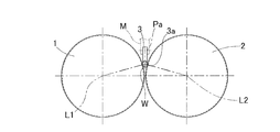
- the processing apparatus mainly includes two feed drums 1 and 2 and a grindstone 3 (FIG. 4).
- the two feed drums 1 and 2 each have a guide screw surface 4 that continues in a spiral shape on the outer periphery, and are driven to rotate about central axes L1 and L2.
- the two feed drums 1 and 2 are installed in parallel at a predetermined interval.
- the feed drums 1 and 2 are configured such that rollers W are brought into rolling contact with guide screw surfaces 4 and 4 facing each other, and the rollers W are passed between the feed drums 1 and 2 by rotation.
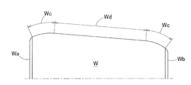
- the grindstone 3 is for processing the crowning portion Wc of the roller W shown in FIG.
- the outer peripheral surface of the roller W is composed of a straight straight portion Wd and crowning portions Wc and Wc formed at both ends in the axial direction of the straight portion Wd.
- Both crowning parts Wc shown in the figure are crowning parts Wc represented by a logarithmic function, and are formed with a crowning part Wc capable of uniforming the surface pressure distribution in the axial direction.
- the roller W is conveyed along the conveying direction while rotating, so that the roller W The crowning portions Wc and Wc are processed on the outer peripheral surface.
- a so-called stick grindstone formed in a plate shape is used as the grindstone 3 in this example.
- a plurality of plate-like grindstones 3 are arranged in parallel in the axial direction of the feed drums 1 and 2 (FIG. 9), and a lower end edge 3 a that is a processing surface of these plate-like grindstones 3 is arranged.
- Each is arranged so as to be inserted between both feed drums 1 and 2.
- each grindstone 3 is configured to be swingable with respect to the support member M in parallel to the central axes L1 and L2 (FIG. 4).
- Each grindstone 3 is configured to be swingable to form the crowning portion Wc represented by the logarithmic function described above. Further, when the grindstone 3 swings, a gap S is provided between the grindstones 3 and 3 so as not to interfere with the adjacent grindstone 3.
- the grindstone 3 is oscillated and displaced when the roller W is conveyed.
- the grindstone 3 is rotated counterclockwise in FIG. 9 with respect to the crowning portion Wc of the roller W.
- the crowning portion Wc having a minute curvature can be realized by causing the outer peripheral surface of the roller W to be inclined and conveyed with respect to the lower end edge portion 3a that is the processing surface of the grindstone 3.
- the two feed drums 1 and 2 are composed of a male feed drum 1 and a female feed drum 2.
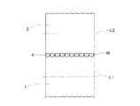
- the guide screw surface 4 of the male feed drum 1 is partitioned from the adjacent peripheral surface portion by the spiral flange 5.
- the feed drums 1 and 2 are rotated in a state where the large end surface Wa of the roller W is in contact with the flange portion 5, whereby the small end surface Wb of the roller W is moved forward (that is, in the conveying direction).
- the roller W can be conveyed toward the downstream side from the upstream side in the conveyance direction indicated by the arrow A1.
- the guide screw surface 4 is divided into two divided screw surface portions 4a and 4b arranged in the axial direction so as to support the outer peripheral surface of the roller W at two positions before and after the roller W.
- a circumferential groove 6 is formed between the axially divided screw surface portions 4a and 4b defined by the flange portion 5. Between the flange portion 5 and the divided screw surface portions 4a and 4b, circumferential grooves 7 and 8 narrower than the circumferential groove 6 between the divided screw surface portions 4a and 4b are formed, respectively.
- the female-side feed drum 2 (FIG. 1) is not provided with the flange portion 5, and has two split screw surface portions 4a arranged in the axial direction that support the outer peripheral surface of the roller W at two positions before and after the roller W. It consists of a guide screw surface 4 including 4b.
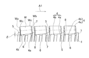
- each of the divided screw surface portions 4a and 4b has a curvature radius R within a predetermined range (in this example, 3 mm or more and 20 mm or less), and an outer diameter. It consists of a circular arc that is convex to the side.
- R a curvature radius
- the divided screw surface portion 4a on the downstream side in the conveyance direction supports the front side portion of the outer peripheral surface of the roller W, and the divided screw surface portion 4b on the upstream side in the conveyance direction A rear portion of the outer peripheral surface of W is supported.
- the rollers are supported at two points of the split screw surface portions 4a and 4b.
- the contact portion of one split screw surface portion 4a, 4b with the roller W is a so-called line contact in a minute region, but is an intermediate point between the axial front end and the axial rear end of the contact portion of the split screw surface portions 4a, 4b. In this case, it is considered to be a point contact.
- the axial dimensions Ha and Hb of the divided screw surface portions 4a and 4b are defined to be the same throughout the entire conveyance direction. Moreover, it is prescribed
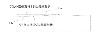
- the roller contact point of the split screw surface portion 4a on the downstream side in the transport direction is the upstream side in the transport direction. It projects from the roller contact point of the divided screw surface portion 4b in the radial direction, and a straight line Lw connecting these two roller contact points is inclined with respect to the lower end edge portion 3a which is the processing surface of the grindstone 3. Accordingly, the straight line Lw that connects the two roller contact points becomes an upward slope from the upstream side of the feed drums 1 and 2 in the conveyance direction to the vicinity of the middle in the conveyance direction.
- the roller contact point of the split screw surface portion 4b is that of the split screw surface portion 4a. It protrudes in the radial direction from the roller contact point, and a straight line Lw connecting these two roller contact points is provided so as to be inclined downward toward the transport direction.
- the split screw surface portions 4a and 4b change the radial difference ⁇ between the roller contact points of the two split screw surface portions 4a and 4b arranged in the axial direction according to the roller passing positions of the feed drums 1 and 2. Specifically, when superfinishing the crowning portion Wc of the tapered roller with this processing device, the radial difference ⁇ is gradually changed from a large setting from the upstream position in the conveying direction of the feed drums 1 and 2 to the middle. On the contrary, from the vicinity of the middle of the feed drums 1 and 2 in the transport direction to the downstream position in the transport direction, conversely, the radius difference ⁇ is gradually changed from a small setting.
- the roller contact points with respect to the conveying direction of the two divided screw surface portions 4a and 4b of the feed drums 1 and 2 are divided into a front divided screw surface portion 4a, a rear divided screw surface portion 4b, and Are changed separately.
- the surface of the roller W guided by contacting the two roller contact points arranged in the axial direction is inclined with respect to the lower edge 3 a that is the processing surface of the grindstone 3. I am letting.
- the inclination angle ⁇ of the straight line Lw connecting the two roller contact points of the two divided screw surface portions 4a and 4b with respect to the feed drum axis L1 is continuously increased from the upstream side in the conveyance direction of the roller W toward the downstream side. It is changing.
- the inclination angle of the outer peripheral surface of the roller W with respect to the processing surface of the grindstone 3 continuously changes.
- the track La from the upstream side to the downstream side in the conveying direction is indicated by a two-dot chain line, and the track Lb about the roller contact point of the rear divided screw surface portion 4b is represented. It is represented by a dotted line.
- the inclination angle ⁇ of the straight line Lw connecting the two roller contact points with the processing surface of the grindstone 3 with respect to the feed drum shaft center L1 increases from small to large as it goes from the upstream side to the downstream side in the conveyance direction of the roller W.
- the split screw surface portions 4a and 4b of the feed drums 1 and 2 are formed so as to be continuously changed.
- the logarithmic curve-shaped crowning portion Wc is a crowning portion Wc represented by a logarithmic function, and can uniform the surface pressure distribution in the axial direction.
- the two feed drums 1 and 2 are installed in parallel, and the rollers W between the feed drums 1 and 2 are rotated by the rotation of the feed drums 1 and 2 while rotating from the upstream side in the conveying direction. It is conveyed toward the side.
- the grinding stone 3 is pressed against the rollers W passing between the feed drums 1 and 2 to process the crowning portion Wc.
- the guide screw surfaces 4 of the feed drums 1 and 2 are divided into two divided screw surface portions 4a and 4b arranged in the axial direction so as to support the outer peripheral surface of the roller W at two positions before and after the roller W.
- the roller W can be inclined with respect to the grindstone 3 at an arbitrary inclination angle.
- the guide screw surface 4 is divided into two divided screw surface portions 4a and 4b arranged in the axial direction, the two front and rear portions of the outer peripheral surface of the roller W can be reliably supported.
- the crowning portions Wc of the plurality of rollers W can be sequentially processed by through-feed processing using the feed drums 1 and 2, so that when the crowning portions Wc of the rollers W are processed one by one or processed by plunge cutting, In comparison, the processing time can be shortened and the processing apparatus can be applied to mass production. Therefore, the manufacturing cost of the roller W can be reduced.
- the shaft center of the feed drum 1 is a cross section and each of the divided screw surface portions 4a and 4b is formed in an arc shape that is convex toward the outer diameter side, the feed drum shaft center L1 of the straight line Lw connecting the two roller contact points. Can be reliably set to a desired inclination angle, and the roller W can be smoothly brought into rolling contact with the divided screw face portions 4a and 4b having an arc shape.
- the split screw face portions 4a and 4b change the radial difference ⁇ between the two split screw face portions 4a and 4b arranged in the axial direction according to the roller passing positions of the feed drums 1 and 2.
- the inclination angle ⁇ of the straight line Lw connecting the two roller contact points can be easily and reliably changed. it can. Therefore, the inclination angle of the outer peripheral surface of the roller W with respect to the processing surface of the grindstone 3 can be easily and reliably changed.
- the feed drum 1 Since the guide screw surface 4 of the feed drum 1 is partitioned from the adjacent peripheral surface portion by the spiral flange portion 5, the feed drum 1 is in a state where the large end surface Wa of the roller W is in contact with the flange portion 5. , 2 can be used to transport the rollers W from the upstream side in the transport direction to the downstream side.
- the conventional through-feed machining method could not process not only logarithm-shaped crowning but also single curvature cut crowning.
- the inclination angle ⁇ of the straight line Lw connecting the two roller contact points of the divided screw surface portions 4a and 4b with respect to the feed drum axis L1 is continuously changed along the conveying direction.
- the tapered roller can be subjected to a logarithmic curve shape crowning process or a crowning process with a small curvature (for example, a curvature radius of 1000 mm or less).
- a small curvature for example, a curvature radius of 1000 mm or less.
- the abrasive grains used for the processing of the crowning portion Wc It can be temporarily stored in the groove 6 and smoothly discharged to the outside of the feed drums 1 and 2. Therefore, the abrasive grains do not remain at the contact portions of the divided screw surface portions 4a and 4b with the roller W, so that the outer peripheral surface of the roller W can be set to a desired inclination angle ⁇ . Accordingly, the crowning portion Wc can be processed with high accuracy.
- This processing device may be used not only for super-finishing of tapered rollers but also for crowning of tapered rollers.
- the workpiece to be processed is not limited to the tapered roller of the tapered roller bearing, and may be a conical member such as a tapered pin or a cylindrical roller of a cylindrical roller bearing.
- two divided screw surface portions arranged in the axial direction are arranged so that the rollers with the small end faces in the transport direction are inclined downward in the transport direction.
- two divided screw surface portions arranged in the axial direction may be formed so that the rollers are inclined in the upward direction of the conveying direction from the vicinity of the middle in the conveying direction of the feed drum.
- the radial difference is gradually changed from a state in which the radial difference is set large from the upstream position in the conveyance direction of the feed drum to the middle, and conversely, the radial difference is varied from the middle position in the conveyance direction of the feed drum to the downstream position in the conveyance direction. Gradually change from a small setting.
- the crowning portion Wc of the roller W is processed using a plurality of grindstones 3, but the crowning portions on the small end face side and the large end face side of the outer peripheral surface of the roller are formed by one grindstone. You may process by a through feed process.
- the male side feed drum 1 in FIG. 1 and the feed drum 52 without the split screw surface portion in FIG. 11A can be installed in parallel, and the crowning portion can be through-feed processed.
Landscapes
- Engineering & Computer Science (AREA)
- Mechanical Engineering (AREA)
- General Engineering & Computer Science (AREA)
- Grinding Of Cylindrical And Plane Surfaces (AREA)
- Grinding And Polishing Of Tertiary Curved Surfaces And Surfaces With Complex Shapes (AREA)
- Rolling Contact Bearings (AREA)
- Grinding-Machine Dressing And Accessory Apparatuses (AREA)
Abstract
L'invention concerne un dispositif et un procédé de façonnage permettant une adaptation à un façonnage de bombé ou un façonnage de superfinition de bombé sur un rouleau, une réduction du temps de façonnage, et une adaptation à une production de masse, et permettant également une application dans le cadre d'un façonnage de bombé de très faible courbure ou de bombé en forme de courbe logarithmique. Le dispositif de façonnage possède sur sa périphérie externe des faces en vis de guidage (4, 4) qui se prolongent chacune de façon hélicoïdale, et deux alimentateurs rotatifs (1, 2) entraînés en rotation autour d'un axe central (L1, L2) sont disposés parallèlement. Les alimentateurs rotatifs (1, 2) mettent un rouleau (w) en contact de roulement sur les faces en vis de guidage (4, 4) qui s'opposent l'une à l'autre, et font passer par roulement ce rouleau (w) entre eux deux. D'autre part, les alimentateurs rotatifs (1, 2) sont équipés d'une meule (3) qui façonne la partie de bombé du rouleau (w) qui passe entre eux deux. La face en vis de guidage (4) des alimentateurs rotatifs (1, 2), est divisée en deux parties face de vis divisée (4a, 4b) s'alignant dans la direction axiale de manière à maintenir la face périphérique externe du rouleau (w) en deux endroits avant et arrière de ce dernier.
Priority Applications (4)
| Application Number | Priority Date | Filing Date | Title |
|---|---|---|---|
| EP11825065.3A EP2617521B1 (fr) | 2010-09-17 | 2011-09-08 | Dispositif et procédé de façonnage |
| CN201180044464.7A CN103108724B (zh) | 2010-09-17 | 2011-09-08 | 加工装置和加工方法 |
| US13/822,370 US9446492B2 (en) | 2010-09-17 | 2011-09-08 | Processing apparatus and processing method |
| US14/933,242 US9700984B2 (en) | 2010-09-17 | 2015-11-05 | Processing method |
Applications Claiming Priority (2)
| Application Number | Priority Date | Filing Date | Title |
|---|---|---|---|
| JP2010208789A JP5602552B2 (ja) | 2010-09-17 | 2010-09-17 | 加工装置 |
| JP2010-208789 | 2010-09-17 |
Related Child Applications (2)
| Application Number | Title | Priority Date | Filing Date |
|---|---|---|---|
| US13/822,370 A-371-Of-International US9446492B2 (en) | 2010-09-17 | 2011-09-08 | Processing apparatus and processing method |
| US14/933,242 Continuation US9700984B2 (en) | 2010-09-17 | 2015-11-05 | Processing method |
Publications (1)
| Publication Number | Publication Date |
|---|---|
| WO2012036062A1 true WO2012036062A1 (fr) | 2012-03-22 |
Family
ID=45831525
Family Applications (1)
| Application Number | Title | Priority Date | Filing Date |
|---|---|---|---|
| PCT/JP2011/070458 WO2012036062A1 (fr) | 2010-09-17 | 2011-09-08 | Dispositif et procédé de façonnage |
Country Status (5)
| Country | Link |
|---|---|
| US (2) | US9446492B2 (fr) |
| EP (2) | EP2617521B1 (fr) |
| JP (1) | JP5602552B2 (fr) |
| CN (1) | CN103108724B (fr) |
| WO (1) | WO2012036062A1 (fr) |
Cited By (3)
| Publication number | Priority date | Publication date | Assignee | Title |
|---|---|---|---|---|
| JP2014000626A (ja) * | 2012-06-18 | 2014-01-09 | Jtekt Corp | 円錐ころ組付け装置 |
| WO2017159467A1 (fr) * | 2016-03-18 | 2017-09-21 | Ntn株式会社 | Palier à rouleaux effilé |
| JP2017172592A (ja) * | 2016-03-18 | 2017-09-28 | Ntn株式会社 | 円すいころ軸受 |
Families Citing this family (10)
| Publication number | Priority date | Publication date | Assignee | Title |
|---|---|---|---|---|
| CN102878206B (zh) * | 2012-08-22 | 2015-04-22 | 宁夏勤昌滚动轴承制造有限公司 | 母线分段对称凸度圆锥滚子及终磨方法 |
| CN103465149B (zh) * | 2013-05-16 | 2015-09-09 | 河南科技大学 | 小端抬高贯穿式圆锥滚子凸度超精研方法 |
| CN103394978B (zh) * | 2013-07-18 | 2016-01-13 | 蒿庆国 | 一种圆锥滚子无心磨床 |
| JP6519227B2 (ja) * | 2015-02-26 | 2019-05-29 | 株式会社ジェイテクト | 加工装置 |
| JP2017094404A (ja) * | 2015-11-18 | 2017-06-01 | Ntn株式会社 | 軸受用ころの超仕上げ加工方法および超仕上げ加工装置 |
| JP6739968B2 (ja) * | 2016-04-01 | 2020-08-12 | Ntn株式会社 | 円すいころ軸受 |
| CN105798712B (zh) * | 2016-05-24 | 2018-02-16 | 洛阳宜华滚动体有限公司 | 一种加工圆锥滚子的软磨工艺及设备 |
| CN110871395A (zh) * | 2019-12-03 | 2020-03-10 | 中南大学 | 一种圆锥滚子轴承的滚子超精加工新设备 |
| DE102019135530A1 (de) * | 2019-12-20 | 2021-06-24 | Supfina Grieshaber Gmbh & Co. Kg | Vorrichtung zur Finishbearbeitung von Wälzkörpern |
| DE102020114006A1 (de) | 2020-05-26 | 2021-12-02 | Schaeffler Technologies AG & Co. KG | Vorrichtung und Verfahren zum Honen von Tonnenrollen |
Citations (6)
| Publication number | Priority date | Publication date | Assignee | Title |
|---|---|---|---|---|
| JPS56121562U (fr) * | 1980-02-14 | 1981-09-16 | ||
| JPH07100743A (ja) | 1993-09-30 | 1995-04-18 | Ntn Corp | 円筒部品の研削装置 |
| JPH07290347A (ja) | 1994-04-21 | 1995-11-07 | Ngk Spark Plug Co Ltd | クラウニング形状物の製造方法と心なし研削盤 |
| JP2003340692A (ja) * | 2002-05-20 | 2003-12-02 | Denso Corp | クラウニング形状を有するローラの製造装置 |
| JP2004322307A (ja) * | 2003-04-09 | 2004-11-18 | Nsk Ltd | 超仕上げ加工装置、超仕上げ加工方法、転動体及び転がり軸受 |
| JP2010030003A (ja) * | 2008-07-30 | 2010-02-12 | Ntn Corp | センタレス研削用調整車ドラム |
Family Cites Families (19)
| Publication number | Priority date | Publication date | Assignee | Title |
|---|---|---|---|---|
| US2043972A (en) * | 1925-03-02 | 1936-06-09 | Motch Merryweather Machinery | Centerless grinding machinery |
| US1767775A (en) * | 1927-08-19 | 1930-06-24 | Jr Edwin E Slick | Grinding machine and method of grinding |
| US1886579A (en) * | 1930-08-12 | 1932-11-08 | Hoover Steel Ball Company | Grinding machine |
| US2002489A (en) * | 1931-07-03 | 1935-05-28 | Cincinnati Grinders Inc | Grinding machine |
| US2132280A (en) * | 1933-07-03 | 1938-10-04 | Bower Roller Bearing Co | Method and means for grinding tapered rolls |
| US2476683A (en) * | 1948-04-17 | 1949-07-19 | Pieri Gino | Polishing apparatus |
| CS176452B1 (fr) * | 1973-08-28 | 1977-06-30 | ||
| JPS6021170B2 (ja) | 1976-09-27 | 1985-05-25 | 株式会社東芝 | 熱硬化性樹脂組成物 |
| JPS56121562A (en) | 1980-02-28 | 1981-09-24 | Mitsubishi Electric Corp | Irradiation controller |
| JPS5930653B2 (ja) | 1981-05-13 | 1984-07-28 | 株式会社東芝 | マイクロ波加熱脱硝装置 |
| DE3225977A1 (de) * | 1982-07-10 | 1984-01-12 | Supfina Maschinenfabrik Hentzen GmbH & Co KG, 5630 Remscheid | Verfahren und vorrichtung zur feinstbearbeitung konvexer oder konkaver mantelflaechen rotationssymmetrischer werkstuecke, insbesondere von waelzlagerrollen |
| JPS5930653A (ja) * | 1982-08-04 | 1984-02-18 | Koyo Seiko Co Ltd | 円筒ころの製造方法 |
| JPS6021170A (ja) | 1983-07-15 | 1985-02-02 | Nisshin Steel Co Ltd | 連続鋳造用ノズル |
| DE4425561C2 (de) * | 1994-07-20 | 1997-02-06 | Supfina Maschf Hentzen | Verfahren und Vorrichtung zum spitzenlosen Kurzhubhonen von Rollen |
| DE19543941C1 (de) * | 1995-11-25 | 1996-10-31 | Skf Gmbh | Vorrichtung zum Honen von Kegelrollen |
| JP4986558B2 (ja) * | 2006-09-20 | 2012-07-25 | Ntn株式会社 | ねじ状クラウニングドラム形状測定方法 |
| CN101367179B (zh) * | 2008-10-16 | 2011-05-11 | 濮阳贝英数控机械设备有限公司 | 圆锥滚子无心磨床及其工作方法 |
| CN101433984B (zh) * | 2008-12-12 | 2011-01-05 | 周良财 | 无心滚珠丝杠磨床及其磨削加工工艺 |
| CN101767297B (zh) * | 2010-03-04 | 2011-07-20 | 濮阳贝英数控机械设备有限公司 | 圆锥滚子无心磨床防倒置进料装置及使用方法 |
-
2010
- 2010-09-17 JP JP2010208789A patent/JP5602552B2/ja not_active Expired - Fee Related
-
2011
- 2011-09-08 EP EP11825065.3A patent/EP2617521B1/fr not_active Not-in-force
- 2011-09-08 US US13/822,370 patent/US9446492B2/en not_active Expired - Fee Related
- 2011-09-08 EP EP16169935.0A patent/EP3100823B1/fr not_active Not-in-force
- 2011-09-08 WO PCT/JP2011/070458 patent/WO2012036062A1/fr active Application Filing
- 2011-09-08 CN CN201180044464.7A patent/CN103108724B/zh not_active Expired - Fee Related
-
2015
- 2015-11-05 US US14/933,242 patent/US9700984B2/en not_active Expired - Fee Related
Patent Citations (6)
| Publication number | Priority date | Publication date | Assignee | Title |
|---|---|---|---|---|
| JPS56121562U (fr) * | 1980-02-14 | 1981-09-16 | ||
| JPH07100743A (ja) | 1993-09-30 | 1995-04-18 | Ntn Corp | 円筒部品の研削装置 |
| JPH07290347A (ja) | 1994-04-21 | 1995-11-07 | Ngk Spark Plug Co Ltd | クラウニング形状物の製造方法と心なし研削盤 |
| JP2003340692A (ja) * | 2002-05-20 | 2003-12-02 | Denso Corp | クラウニング形状を有するローラの製造装置 |
| JP2004322307A (ja) * | 2003-04-09 | 2004-11-18 | Nsk Ltd | 超仕上げ加工装置、超仕上げ加工方法、転動体及び転がり軸受 |
| JP2010030003A (ja) * | 2008-07-30 | 2010-02-12 | Ntn Corp | センタレス研削用調整車ドラム |
Cited By (4)
| Publication number | Priority date | Publication date | Assignee | Title |
|---|---|---|---|---|
| JP2014000626A (ja) * | 2012-06-18 | 2014-01-09 | Jtekt Corp | 円錐ころ組付け装置 |
| WO2017159467A1 (fr) * | 2016-03-18 | 2017-09-21 | Ntn株式会社 | Palier à rouleaux effilé |
| JP2017172592A (ja) * | 2016-03-18 | 2017-09-28 | Ntn株式会社 | 円すいころ軸受 |
| US11143235B2 (en) | 2016-03-18 | 2021-10-12 | Ntn Corporation | Tapered roller bearing |
Also Published As
| Publication number | Publication date |
|---|---|
| JP2012061571A (ja) | 2012-03-29 |
| US9446492B2 (en) | 2016-09-20 |
| US20160052100A1 (en) | 2016-02-25 |
| CN103108724A (zh) | 2013-05-15 |
| JP5602552B2 (ja) | 2014-10-08 |
| CN103108724B (zh) | 2015-06-03 |
| EP2617521A4 (fr) | 2018-01-24 |
| EP2617521A1 (fr) | 2013-07-24 |
| US20130171914A1 (en) | 2013-07-04 |
| US9700984B2 (en) | 2017-07-11 |
| EP2617521B1 (fr) | 2019-07-31 |
| EP3100823A1 (fr) | 2016-12-07 |
| EP3100823B1 (fr) | 2018-04-11 |
Similar Documents
| Publication | Publication Date | Title |
|---|---|---|
| JP5602552B2 (ja) | 加工装置 | |
| WO2017086120A1 (fr) | Procédé et dispositif pour superfinir un rouleau de palier | |
| JP5456356B2 (ja) | ころ端面加工用ワーク供給装置、ころ端面加工機、および転がり軸受用ころ | |
| JP2004322307A (ja) | 超仕上げ加工装置、超仕上げ加工方法、転動体及び転がり軸受 | |
| JP7179984B2 (ja) | 少なくとも1つの回転要素を形成するための装置および方法、ならびに装置の少なくとも1つの制御ホイールを処理するための方法 | |
| JP5371296B2 (ja) | ねじ状ドラムの研削方法 | |
| JP5239589B2 (ja) | 研削加工装置、及び研削加工方法 | |
| CN105593544B (zh) | 圆锥滚子的制造方法以及圆锥滚子轴承 | |
| JP4923369B2 (ja) | センタレス研削盤 | |
| US2595121A (en) | Antifriction bearing | |
| JP2010030003A (ja) | センタレス研削用調整車ドラム | |
| WO2005028890A1 (fr) | Roulement a rouleaux d'auto-alignement et procede de traitement associe | |
| JP6517105B2 (ja) | ころ軸受転走面の超仕上げ加工方法 | |
| JP2018187735A (ja) | 心なし研削盤用の回転送り装置 | |
| US1783034A (en) | Process of producing noncylindrical articles | |
| US3913275A (en) | Lapping, pressure grinding and flash roll apparatus and method | |
| US10537976B2 (en) | Former rotary dresser and dressing method | |
| RU2213652C2 (ru) | Устройство для безабразивной доводки дорожек качения колец подшипников | |
| RU2207943C2 (ru) | Способ безабразивной обработки дорожек качения подшипников и устройство для его осуществления | |
| RU2264904C2 (ru) | Способ двусторонней финишной обработки торцов цилиндрических деталей | |
| JPH11165249A (ja) | ベルト式研磨装置 | |
| JP6409474B2 (ja) | 砥石、砥石面形状の決定方法、及び、砥石の製造方法 | |
| JPH11277447A (ja) | 超仕上用砥石 | |
| JP2015102191A (ja) | ころおよびころのセンタレス研削方法 | |
| JPH05245749A (ja) | ころがり部品の加工方法 |
Legal Events
| Date | Code | Title | Description |
|---|---|---|---|
| WWE | Wipo information: entry into national phase |
Ref document number: 201180044464.7 Country of ref document: CN |
|
| 121 | Ep: the epo has been informed by wipo that ep was designated in this application |
Ref document number: 11825065 Country of ref document: EP Kind code of ref document: A1 |
|
| WWE | Wipo information: entry into national phase |
Ref document number: 13822370 Country of ref document: US Ref document number: 2011825065 Country of ref document: EP |
|
| NENP | Non-entry into the national phase |
Ref country code: DE |