WO2012036062A1 - Processing apparatus and processing method - Google Patents
Processing apparatus and processing method Download PDFInfo
- Publication number
- WO2012036062A1 WO2012036062A1 PCT/JP2011/070458 JP2011070458W WO2012036062A1 WO 2012036062 A1 WO2012036062 A1 WO 2012036062A1 JP 2011070458 W JP2011070458 W JP 2011070458W WO 2012036062 A1 WO2012036062 A1 WO 2012036062A1
- Authority
- WO
- WIPO (PCT)
- Prior art keywords
- roller
- processing
- feed
- crowning
- screw surface
- Prior art date
Links
Images


Classifications
-
- B—PERFORMING OPERATIONS; TRANSPORTING
- B24—GRINDING; POLISHING
- B24B—MACHINES, DEVICES, OR PROCESSES FOR GRINDING OR POLISHING; DRESSING OR CONDITIONING OF ABRADING SURFACES; FEEDING OF GRINDING, POLISHING, OR LAPPING AGENTS
- B24B5/00—Machines or devices designed for grinding surfaces of revolution on work, including those which also grind adjacent plane surfaces; Accessories therefor
- B24B5/02—Machines or devices designed for grinding surfaces of revolution on work, including those which also grind adjacent plane surfaces; Accessories therefor involving centres or chucks for holding work
- B24B5/04—Machines or devices designed for grinding surfaces of revolution on work, including those which also grind adjacent plane surfaces; Accessories therefor involving centres or chucks for holding work for grinding cylindrical surfaces externally
-
- B—PERFORMING OPERATIONS; TRANSPORTING
- B24—GRINDING; POLISHING
- B24B—MACHINES, DEVICES, OR PROCESSES FOR GRINDING OR POLISHING; DRESSING OR CONDITIONING OF ABRADING SURFACES; FEEDING OF GRINDING, POLISHING, OR LAPPING AGENTS
- B24B19/00—Single-purpose machines or devices for particular grinding operations not covered by any other main group
- B24B19/02—Single-purpose machines or devices for particular grinding operations not covered by any other main group for grinding grooves, e.g. on shafts, in casings, in tubes, homokinetic joint elements
- B24B19/06—Single-purpose machines or devices for particular grinding operations not covered by any other main group for grinding grooves, e.g. on shafts, in casings, in tubes, homokinetic joint elements for grinding races, e.g. roller races
-
- B—PERFORMING OPERATIONS; TRANSPORTING
- B24—GRINDING; POLISHING
- B24B—MACHINES, DEVICES, OR PROCESSES FOR GRINDING OR POLISHING; DRESSING OR CONDITIONING OF ABRADING SURFACES; FEEDING OF GRINDING, POLISHING, OR LAPPING AGENTS
- B24B5/00—Machines or devices designed for grinding surfaces of revolution on work, including those which also grind adjacent plane surfaces; Accessories therefor
- B24B5/18—Machines or devices designed for grinding surfaces of revolution on work, including those which also grind adjacent plane surfaces; Accessories therefor involving centreless means for supporting, guiding, floating or rotating work
- B24B5/24—Machines or devices designed for grinding surfaces of revolution on work, including those which also grind adjacent plane surfaces; Accessories therefor involving centreless means for supporting, guiding, floating or rotating work for grinding conical surfaces
- B24B5/245—Machines or devices designed for grinding surfaces of revolution on work, including those which also grind adjacent plane surfaces; Accessories therefor involving centreless means for supporting, guiding, floating or rotating work for grinding conical surfaces for mass articles
-
- F—MECHANICAL ENGINEERING; LIGHTING; HEATING; WEAPONS; BLASTING
- F16—ENGINEERING ELEMENTS AND UNITS; GENERAL MEASURES FOR PRODUCING AND MAINTAINING EFFECTIVE FUNCTIONING OF MACHINES OR INSTALLATIONS; THERMAL INSULATION IN GENERAL
- F16C—SHAFTS; FLEXIBLE SHAFTS; ELEMENTS OR CRANKSHAFT MECHANISMS; ROTARY BODIES OTHER THAN GEARING ELEMENTS; BEARINGS
- F16C33/00—Parts of bearings; Special methods for making bearings or parts thereof
- F16C33/30—Parts of ball or roller bearings
- F16C33/34—Rollers; Needles
- F16C33/36—Rollers; Needles with bearing-surfaces other than cylindrical, e.g. tapered; with grooves in the bearing surfaces
- F16C33/366—Tapered rollers, i.e. rollers generally shaped as truncated cones
Definitions
- the present invention relates to a processing apparatus and a processing method applied to crowning processing and crowning superfinishing processing of cylindrical rollers and tapered rollers.
- FIG. 11 (A) is a plan view of a conventional feed drum
- FIG. 11 (B) is a front view of the main part of the feed drum.
- a tapered roller which is a workpiece W can be subjected to through-feed super finishing using only the outer diameter straight portion 50 using the feed drums 51 and 52 (Patent Document 1).
- the feed drums 51 and 52 linearly support the work W, the inclination angle of the grindstone 53 and the work W is constant throughout the feed drum. Therefore, it is impossible to superfinish the crowning portion 54 of the workpiece W using the feed drums 51 and 52.
- the object of the present invention is applied to roller crowning and crowning super-finishing, which can reduce machining time, can be applied to mass production, and can cope with crowning with a small curvature, logarithmic curve shape, etc. It is to provide a versatile processing apparatus and processing method that can be used.
- the processing device is a processing device for processing a crowning portion of a roller, and has two guide drums each having a spiral guide screw surface on the outer periphery and driven to rotate about a central axis in parallel. These feed drums are made by rolling the rollers on the guide screw surfaces facing each other and passing the rollers between the two feed drums by rotation, and processing the crowning portion of the rollers passing between the feed drums. Two divided screw face portions arranged in the axial direction so that the guide screw face of either one of the two feed drums supports the outer peripheral face of the roller at two positions on the front and rear sides of the same roller. It is divided into
- two feed drums are installed in parallel, and the rollers between the feed drums are conveyed from the upstream side to the downstream side in the conveyance direction while rotating by the rotation of the feed drum.
- the crown is pressed by pressing a grindstone while passing between the feed drums.
- the guide screw surface of any one of the feed drums is divided into two divided screw surface portions arranged in the axial direction so as to support the outer peripheral surface of the roller at two positions on the front and rear sides of the roller.
- a radius difference can be given to the roller contact point of the thread surface portion, and the roller can be inclined at an arbitrary inclination angle with respect to the grindstone.
- the guide screw surface is divided into two divided screw surface portions arranged in the axial direction, the two front and rear portions of the outer peripheral surface of the roller can be reliably supported. Therefore, the crowning part of multiple rollers can be processed sequentially by through-feed machining using a feed drum, so the machining time is shortened compared to machining the crowning parts of rollers one by one or by plunge cutting.
- the present processing apparatus can be applied to mass production. Therefore, it is possible to reduce the manufacturing cost of the rollers.
- each divided screw surface portion may have an arc shape that is convex toward the outer diameter side.
- the outer peripheral surface of the roller can be reliably set to a desired inclination angle with respect to the processing surface of the grindstone, and the roller can be smoothly brought into rolling contact with the divided screw surface portion having an arc shape.
- the thread surface portion may be configured such that a radial difference between roller contact points of two divided thread surface portions arranged in the axial direction is changed depending on a roller passing position of the feed drum. In this way, by changing the radius difference between the roller contact points of the two divided screw surface portions arranged in the axial direction, the inclination angle of the outer peripheral surface of the roller with respect to the processing surface of the grindstone can be easily and reliably changed.
- the roller contact point of either one of the two divided screw surface portions aligned in the axial direction protrude in the radial direction from the roller contact point of the other divided screw surface portion the roller contact of these two points You may make it incline the surface of the roller guided in contact with a point with respect to the processing surface of the said grindstone.
- the crowning portion of the roller can be processed by inclining the outer peripheral surface of the roller with respect to the processing surface of the grindstone.
- the inclination angle of the straight line connecting the two roller contact points of the two split screw surface portions with respect to the feed drum axis is continuously changed from the upstream side toward the downstream side in the roller conveying direction. It may be.
- the inclination angle of the outer peripheral surface of the roller with respect to the processing surface of the grindstone can be continuously changed along the conveying direction. Therefore, for example, a logarithmic curve shape crowning process or a crowning process with a small curvature can be performed on the rollers.
- the guide screw surface of the feed drum may be separated from the adjacent peripheral surface portion by a spiral flange.
- the roller can be transported from the upstream side in the transport direction to the downstream side by rotating the feed drum with the end face of the roller in contact with the flange.
- the roller may be a cylindrical roller or a tapered roller.
- the processing method of the present invention is a processing method for processing a crowning portion of a roller, and has two guide drums that have a guide screw surface that follows a spiral shape on the outer periphery and are driven to rotate about a central axis in parallel.
- These feed drums are configured such that rollers are brought into contact with guide screw surfaces facing each other, the rollers are passed between both feed drums by rotation, and a crowning portion of the rollers passing between the feed drums is processed by a grindstone.
- the divided screw face portion arranged in the axial direction so that the guide screw face of any one of the two feed drums supports the outer peripheral face of the roller at two positions on the front and rear sides of the roller. It is divided into
- two feed drums are installed in parallel, and the rollers between the feed drums are conveyed from the upstream side to the downstream side in the conveyance direction while rotating by the rotation of the feed drum.
- the crown is pressed by pressing a grindstone while passing between the feed drums.
- the guide screw surface of any one of the feed drums is divided into two divided screw surface portions arranged in the axial direction so as to support the outer peripheral surface of the roller at two positions on the front and rear sides of the roller.
- the roller can be inclined at an arbitrary inclination angle with respect to the grindstone by reliably supporting the front and rear two portions of the outer peripheral surface of the roller on the surface portion.
- the crowning part of multiple rollers can be processed sequentially by through-feed machining using a feed drum, so the machining time is shortened compared to machining the crowning parts of rollers one by one or by plunge cutting. And this processing method can be applied to mass production. Therefore, the manufacturing cost of the roller can be reduced.
- FIG. (A) is a top view of the feed drum of a prior art example
- (B) is a principal part front view of the feed drum.
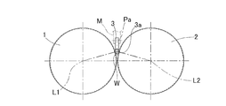
- the processing apparatus mainly includes two feed drums 1 and 2 and a grindstone 3 (FIG. 4).
- the two feed drums 1 and 2 each have a guide screw surface 4 that continues in a spiral shape on the outer periphery, and are driven to rotate about central axes L1 and L2.
- the two feed drums 1 and 2 are installed in parallel at a predetermined interval.
- the feed drums 1 and 2 are configured such that rollers W are brought into rolling contact with guide screw surfaces 4 and 4 facing each other, and the rollers W are passed between the feed drums 1 and 2 by rotation.
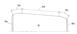
- the grindstone 3 is for processing the crowning portion Wc of the roller W shown in FIG.
- the outer peripheral surface of the roller W is composed of a straight straight portion Wd and crowning portions Wc and Wc formed at both ends in the axial direction of the straight portion Wd.
- Both crowning parts Wc shown in the figure are crowning parts Wc represented by a logarithmic function, and are formed with a crowning part Wc capable of uniforming the surface pressure distribution in the axial direction.
- the roller W is conveyed along the conveying direction while rotating, so that the roller W The crowning portions Wc and Wc are processed on the outer peripheral surface.
- a so-called stick grindstone formed in a plate shape is used as the grindstone 3 in this example.
- a plurality of plate-like grindstones 3 are arranged in parallel in the axial direction of the feed drums 1 and 2 (FIG. 9), and a lower end edge 3 a that is a processing surface of these plate-like grindstones 3 is arranged.
- Each is arranged so as to be inserted between both feed drums 1 and 2.
- each grindstone 3 is configured to be swingable with respect to the support member M in parallel to the central axes L1 and L2 (FIG. 4).
- Each grindstone 3 is configured to be swingable to form the crowning portion Wc represented by the logarithmic function described above. Further, when the grindstone 3 swings, a gap S is provided between the grindstones 3 and 3 so as not to interfere with the adjacent grindstone 3.
- the grindstone 3 is oscillated and displaced when the roller W is conveyed.
- the grindstone 3 is rotated counterclockwise in FIG. 9 with respect to the crowning portion Wc of the roller W.
- the crowning portion Wc having a minute curvature can be realized by causing the outer peripheral surface of the roller W to be inclined and conveyed with respect to the lower end edge portion 3a that is the processing surface of the grindstone 3.
- the two feed drums 1 and 2 are composed of a male feed drum 1 and a female feed drum 2.
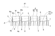
- the guide screw surface 4 of the male feed drum 1 is partitioned from the adjacent peripheral surface portion by the spiral flange 5.
- the feed drums 1 and 2 are rotated in a state where the large end surface Wa of the roller W is in contact with the flange portion 5, whereby the small end surface Wb of the roller W is moved forward (that is, in the conveying direction).
- the roller W can be conveyed toward the downstream side from the upstream side in the conveyance direction indicated by the arrow A1.
- the guide screw surface 4 is divided into two divided screw surface portions 4a and 4b arranged in the axial direction so as to support the outer peripheral surface of the roller W at two positions before and after the roller W.
- a circumferential groove 6 is formed between the axially divided screw surface portions 4a and 4b defined by the flange portion 5. Between the flange portion 5 and the divided screw surface portions 4a and 4b, circumferential grooves 7 and 8 narrower than the circumferential groove 6 between the divided screw surface portions 4a and 4b are formed, respectively.
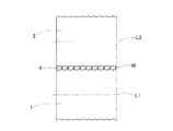
- the female-side feed drum 2 (FIG. 1) is not provided with the flange portion 5, and has two split screw surface portions 4a arranged in the axial direction that support the outer peripheral surface of the roller W at two positions before and after the roller W. It consists of a guide screw surface 4 including 4b.
- each of the divided screw surface portions 4a and 4b has a curvature radius R within a predetermined range (in this example, 3 mm or more and 20 mm or less), and an outer diameter. It consists of a circular arc that is convex to the side.
- R a curvature radius
- the divided screw surface portion 4a on the downstream side in the conveyance direction supports the front side portion of the outer peripheral surface of the roller W, and the divided screw surface portion 4b on the upstream side in the conveyance direction A rear portion of the outer peripheral surface of W is supported.
- the rollers are supported at two points of the split screw surface portions 4a and 4b.
- the contact portion of one split screw surface portion 4a, 4b with the roller W is a so-called line contact in a minute region, but is an intermediate point between the axial front end and the axial rear end of the contact portion of the split screw surface portions 4a, 4b. In this case, it is considered to be a point contact.
- the axial dimensions Ha and Hb of the divided screw surface portions 4a and 4b are defined to be the same throughout the entire conveyance direction. Moreover, it is prescribed
- the roller contact point of the split screw surface portion 4a on the downstream side in the transport direction is the upstream side in the transport direction. It projects from the roller contact point of the divided screw surface portion 4b in the radial direction, and a straight line Lw connecting these two roller contact points is inclined with respect to the lower end edge portion 3a which is the processing surface of the grindstone 3. Accordingly, the straight line Lw that connects the two roller contact points becomes an upward slope from the upstream side of the feed drums 1 and 2 in the conveyance direction to the vicinity of the middle in the conveyance direction.
- the roller contact point of the split screw surface portion 4b is that of the split screw surface portion 4a. It protrudes in the radial direction from the roller contact point, and a straight line Lw connecting these two roller contact points is provided so as to be inclined downward toward the transport direction.
- the split screw surface portions 4a and 4b change the radial difference ⁇ between the roller contact points of the two split screw surface portions 4a and 4b arranged in the axial direction according to the roller passing positions of the feed drums 1 and 2. Specifically, when superfinishing the crowning portion Wc of the tapered roller with this processing device, the radial difference ⁇ is gradually changed from a large setting from the upstream position in the conveying direction of the feed drums 1 and 2 to the middle. On the contrary, from the vicinity of the middle of the feed drums 1 and 2 in the transport direction to the downstream position in the transport direction, conversely, the radius difference ⁇ is gradually changed from a small setting.
- the roller contact points with respect to the conveying direction of the two divided screw surface portions 4a and 4b of the feed drums 1 and 2 are divided into a front divided screw surface portion 4a, a rear divided screw surface portion 4b, and Are changed separately.
- the surface of the roller W guided by contacting the two roller contact points arranged in the axial direction is inclined with respect to the lower edge 3 a that is the processing surface of the grindstone 3. I am letting.
- the inclination angle ⁇ of the straight line Lw connecting the two roller contact points of the two divided screw surface portions 4a and 4b with respect to the feed drum axis L1 is continuously increased from the upstream side in the conveyance direction of the roller W toward the downstream side. It is changing.
- the inclination angle of the outer peripheral surface of the roller W with respect to the processing surface of the grindstone 3 continuously changes.
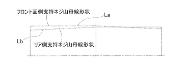
- the track La from the upstream side to the downstream side in the conveying direction is indicated by a two-dot chain line, and the track Lb about the roller contact point of the rear divided screw surface portion 4b is represented. It is represented by a dotted line.
- the inclination angle ⁇ of the straight line Lw connecting the two roller contact points with the processing surface of the grindstone 3 with respect to the feed drum shaft center L1 increases from small to large as it goes from the upstream side to the downstream side in the conveyance direction of the roller W.
- the split screw surface portions 4a and 4b of the feed drums 1 and 2 are formed so as to be continuously changed.
- the logarithmic curve-shaped crowning portion Wc is a crowning portion Wc represented by a logarithmic function, and can uniform the surface pressure distribution in the axial direction.
- the two feed drums 1 and 2 are installed in parallel, and the rollers W between the feed drums 1 and 2 are rotated by the rotation of the feed drums 1 and 2 while rotating from the upstream side in the conveying direction. It is conveyed toward the side.
- the grinding stone 3 is pressed against the rollers W passing between the feed drums 1 and 2 to process the crowning portion Wc.
- the guide screw surfaces 4 of the feed drums 1 and 2 are divided into two divided screw surface portions 4a and 4b arranged in the axial direction so as to support the outer peripheral surface of the roller W at two positions before and after the roller W.
- the roller W can be inclined with respect to the grindstone 3 at an arbitrary inclination angle.
- the guide screw surface 4 is divided into two divided screw surface portions 4a and 4b arranged in the axial direction, the two front and rear portions of the outer peripheral surface of the roller W can be reliably supported.
- the crowning portions Wc of the plurality of rollers W can be sequentially processed by through-feed processing using the feed drums 1 and 2, so that when the crowning portions Wc of the rollers W are processed one by one or processed by plunge cutting, In comparison, the processing time can be shortened and the processing apparatus can be applied to mass production. Therefore, the manufacturing cost of the roller W can be reduced.
- the shaft center of the feed drum 1 is a cross section and each of the divided screw surface portions 4a and 4b is formed in an arc shape that is convex toward the outer diameter side, the feed drum shaft center L1 of the straight line Lw connecting the two roller contact points. Can be reliably set to a desired inclination angle, and the roller W can be smoothly brought into rolling contact with the divided screw face portions 4a and 4b having an arc shape.
- the split screw face portions 4a and 4b change the radial difference ⁇ between the two split screw face portions 4a and 4b arranged in the axial direction according to the roller passing positions of the feed drums 1 and 2.
- the inclination angle ⁇ of the straight line Lw connecting the two roller contact points can be easily and reliably changed. it can. Therefore, the inclination angle of the outer peripheral surface of the roller W with respect to the processing surface of the grindstone 3 can be easily and reliably changed.
- the feed drum 1 Since the guide screw surface 4 of the feed drum 1 is partitioned from the adjacent peripheral surface portion by the spiral flange portion 5, the feed drum 1 is in a state where the large end surface Wa of the roller W is in contact with the flange portion 5. , 2 can be used to transport the rollers W from the upstream side in the transport direction to the downstream side.
- the conventional through-feed machining method could not process not only logarithm-shaped crowning but also single curvature cut crowning.
- the inclination angle ⁇ of the straight line Lw connecting the two roller contact points of the divided screw surface portions 4a and 4b with respect to the feed drum axis L1 is continuously changed along the conveying direction.
- the tapered roller can be subjected to a logarithmic curve shape crowning process or a crowning process with a small curvature (for example, a curvature radius of 1000 mm or less).
- a small curvature for example, a curvature radius of 1000 mm or less.
- the abrasive grains used for the processing of the crowning portion Wc It can be temporarily stored in the groove 6 and smoothly discharged to the outside of the feed drums 1 and 2. Therefore, the abrasive grains do not remain at the contact portions of the divided screw surface portions 4a and 4b with the roller W, so that the outer peripheral surface of the roller W can be set to a desired inclination angle ⁇ . Accordingly, the crowning portion Wc can be processed with high accuracy.
- This processing device may be used not only for super-finishing of tapered rollers but also for crowning of tapered rollers.
- the workpiece to be processed is not limited to the tapered roller of the tapered roller bearing, and may be a conical member such as a tapered pin or a cylindrical roller of a cylindrical roller bearing.
- two divided screw surface portions arranged in the axial direction are arranged so that the rollers with the small end faces in the transport direction are inclined downward in the transport direction.
- two divided screw surface portions arranged in the axial direction may be formed so that the rollers are inclined in the upward direction of the conveying direction from the vicinity of the middle in the conveying direction of the feed drum.
- the radial difference is gradually changed from a state in which the radial difference is set large from the upstream position in the conveyance direction of the feed drum to the middle, and conversely, the radial difference is varied from the middle position in the conveyance direction of the feed drum to the downstream position in the conveyance direction. Gradually change from a small setting.
- the crowning portion Wc of the roller W is processed using a plurality of grindstones 3, but the crowning portions on the small end face side and the large end face side of the outer peripheral surface of the roller are formed by one grindstone. You may process by a through feed process.
- the male side feed drum 1 in FIG. 1 and the feed drum 52 without the split screw surface portion in FIG. 11A can be installed in parallel, and the crowning portion can be through-feed processed.
Landscapes
- Engineering & Computer Science (AREA)
- Mechanical Engineering (AREA)
- General Engineering & Computer Science (AREA)
- Grinding Of Cylindrical And Plane Surfaces (AREA)
- Grinding And Polishing Of Tertiary Curved Surfaces And Surfaces With Complex Shapes (AREA)
- Rolling Contact Bearings (AREA)
- Grinding-Machine Dressing And Accessory Apparatuses (AREA)
Abstract
Provided are a processing apparatus and a processing method that are suitable for use in roller crowning or crowning super-finishing, reduce processing time, are suitable for use in mass production, and can be used for small curvature radius crowning and logarithmic curve-shaped crowning. In the processing apparatus, two feed drums (1, 2) which have continuous spiral guide screw surfaces (4, 4) on the outer peripheries thereof and are rotated about center shafts (L1, L2) are disposed parallel to each other. A roller (W) is brought into contact with and rolled on the mutually opposing guide screw surfaces (4, 4) of the feed drums (1, 2), and the roller (W) passes between both feed drums (1, 2) due to rotation. The processing apparatus is provided with a grindstone (3) for processing a crowning section of the roller (W) that passes between the feed drums (1, 2). Each of the guide screw surfaces (4) of the feed drums (1, 2) is axially divided into two division screw surface sections (4a, 4b) so as to support the outer peripheral surface of the roller (W) at one position at the front and one position at the rear of said roller (W).
Description
本出願は、2010年9月17日出願の特願2010-208789の優先権を主張するものであり、その全体を参照により本願の一部をなすものとして引用する。
This application claims the priority of Japanese Patent Application No. 2010-208789 filed on Sep. 17, 2010, which is incorporated herein by reference in its entirety.
この発明は、円筒ころおよび円すいころのクラウニング加工やクラウニング超仕上げ加工に適用される加工装置および加工方法に関する。
The present invention relates to a processing apparatus and a processing method applied to crowning processing and crowning superfinishing processing of cylindrical rollers and tapered rollers.
図11(A)は、従来例のフィードドラムの平面図であり、図11(B)は、同フィードドラムの要部正面図である。ワークWである例えば円すいころにおいては、外径ストレート部50のみフィードドラム51,52を用いたスルーフィード超仕上げ加工が可能である(特許文献1)。このときフィードドラム51,52は、ワークWを線支持するため、砥石53とワークWの傾斜角度はフィードドラム全域において一定である。したがって、フィードドラム51,52を用いてワークWのクラウニング部54を超仕上げすることは不可能である。
FIG. 11 (A) is a plan view of a conventional feed drum, and FIG. 11 (B) is a front view of the main part of the feed drum. For example, a tapered roller which is a workpiece W can be subjected to through-feed super finishing using only the outer diameter straight portion 50 using the feed drums 51 and 52 (Patent Document 1). At this time, since the feed drums 51 and 52 linearly support the work W, the inclination angle of the grindstone 53 and the work W is constant throughout the feed drum. Therefore, it is impossible to superfinish the crowning portion 54 of the workpiece W using the feed drums 51 and 52.
円すいころのクラウニング部は、1個ずつ単品で超仕上げ加工するため、加工時間が長く、大量生産に適用できない。外径面をクラウニング形状に成形した砥石で、プランジカットにより円すいころのクラウニング部を超仕上げ加工する場合も、加工時間が長く、量産に適用できない。センターレス研削盤を用い、砥石と調整車の外径面にR形状を付けて円すいころにクラウニング成形する方法(特許文献2)では、曲率半径1000mm以下のクラウニングや対数曲線形状のクラウニング加工に対応できない。従来のスルーフィード加工法で、円筒ころにクラウニング成形する場合、単一Rまたは単一Rの組合せによる複合R形状しか成形できない制約があった。
ク ラ The crowning part of tapered rollers is superfinished one by one, so the processing time is long and cannot be applied to mass production. Even when superfinishing the crowning part of a tapered roller by plunge cutting with a grindstone whose outer diameter surface is formed into a crowning shape, the processing time is long and cannot be applied to mass production. Using a centerless grinding machine, the outer diameter surfaces of the grinding wheel and adjustment wheel are rounded and crowned into tapered rollers (Patent Document 2), and can be used for crowning with a radius of curvature of 1000 mm or less and logarithmic curve crowning. Can not. When crowning molding is performed on cylindrical rollers by a conventional through-feed processing method, there is a limitation that only a single R or a composite R shape by a combination of a single R can be molded.
この発明の目的は、ころのクラウニング加工やクラウニング超仕上げ加工に適用され、加工時間の短縮を図り、量産に適用できると共に、微小な曲率のクラウニングや対数曲線形状のクラウニング加工等に対応することができる汎用性の高い加工装置および加工方法を提供することである。
The object of the present invention is applied to roller crowning and crowning super-finishing, which can reduce machining time, can be applied to mass production, and can cope with crowning with a small curvature, logarithmic curve shape, etc. It is to provide a versatile processing apparatus and processing method that can be used.
この発明の加工装置は、ころのクラウニング部を加工する加工装置であって、それぞれ螺旋状に続く案内ねじ面を外周に有し、中心軸回りに回転駆動される2本のフィードドラムを平行に設置し、これらフィードドラムは、互いに対向する案内ねじ面にころを転接させて回転により両フィードドラム間に前記ころを通過させるものであり、このフィードドラム間を通過するころのクラウニング部を加工する砥石を備え、前記2本のフィードドラムのうちいずれか一方のフィードドラムの案内ねじ面は、ころの外周面を同ころの前後2箇所で支持するように軸方向に並ぶ2つの分割ねじ面部に分割されている。
The processing device according to the present invention is a processing device for processing a crowning portion of a roller, and has two guide drums each having a spiral guide screw surface on the outer periphery and driven to rotate about a central axis in parallel. These feed drums are made by rolling the rollers on the guide screw surfaces facing each other and passing the rollers between the two feed drums by rotation, and processing the crowning portion of the rollers passing between the feed drums. Two divided screw face portions arranged in the axial direction so that the guide screw face of either one of the two feed drums supports the outer peripheral face of the roller at two positions on the front and rear sides of the same roller. It is divided into
この構成によると、2本のフィードドラムを平行に設置し、このフィードドラムの回転によりフィードドラム間のころが自転しながら搬送方向上流側から下流側に向かって搬送される。このフィードドラム間を通過するころに砥石を加圧してクラウニング部を加工する。このとき、いずれか一方のフィードドラムの案内ねじ面は、ころの外周面を同ころの前後2箇所で支持するように軸方向に並ぶ2つの分割ねじ面部に分割されているため、2つの分割ねじ面部のころ接触点に半径差を与えることができて、ころを砥石に対して任意の傾斜角度で傾斜させることができる。また、案内ねじ面が軸方向に並ぶ2つの分割ねじ面部に分割されているため、ころの外周面の前後2箇所を確実に支持することができる。したがって、複数のころのクラウニング部をフィードドラムを用いたスルーフィード加工で順次加工できるので、ころのクラウニング部を1個ずつ単品で加工したりプランジカットにより加工する場合に比べて、加工時間を短縮して加工することができ、本加工装置を大量生産に適用することができる。そのため、ころの製造コストの低減を図れる
According to this configuration, two feed drums are installed in parallel, and the rollers between the feed drums are conveyed from the upstream side to the downstream side in the conveyance direction while rotating by the rotation of the feed drum. The crown is pressed by pressing a grindstone while passing between the feed drums. At this time, the guide screw surface of any one of the feed drums is divided into two divided screw surface portions arranged in the axial direction so as to support the outer peripheral surface of the roller at two positions on the front and rear sides of the roller. A radius difference can be given to the roller contact point of the thread surface portion, and the roller can be inclined at an arbitrary inclination angle with respect to the grindstone. Further, since the guide screw surface is divided into two divided screw surface portions arranged in the axial direction, the two front and rear portions of the outer peripheral surface of the roller can be reliably supported. Therefore, the crowning part of multiple rollers can be processed sequentially by through-feed machining using a feed drum, so the machining time is shortened compared to machining the crowning parts of rollers one by one or by plunge cutting. Thus, the present processing apparatus can be applied to mass production. Therefore, it is possible to reduce the manufacturing cost of the rollers.
前記フィードドラムの軸心を通る断面で、各分割ねじ面部は、外径側に凸となる円弧形状であっても良い。この場合、砥石の加工面に対し、ころの外周面を所望の傾斜角度に確実に設定することができるうえ、ころを、円弧形状からなる分割ねじ面部に滑らかに転接させることができる。前記ねじ面部は、軸方向に並ぶ2つの分割ねじ面部のころ接触点の半径差を、前記フィードドラムのころ通過位置によって変化させたものとしても良い。このように軸方向に並ぶ2つの分割ねじ面部のころ接触点の半径差を変化させることで、砥石の加工面に対するころの外周面の傾斜角度を容易に且つ確実に変化させることができる。
In the cross section passing through the axis of the feed drum, each divided screw surface portion may have an arc shape that is convex toward the outer diameter side. In this case, the outer peripheral surface of the roller can be reliably set to a desired inclination angle with respect to the processing surface of the grindstone, and the roller can be smoothly brought into rolling contact with the divided screw surface portion having an arc shape. The thread surface portion may be configured such that a radial difference between roller contact points of two divided thread surface portions arranged in the axial direction is changed depending on a roller passing position of the feed drum. In this way, by changing the radius difference between the roller contact points of the two divided screw surface portions arranged in the axial direction, the inclination angle of the outer peripheral surface of the roller with respect to the processing surface of the grindstone can be easily and reliably changed.
軸方向に並ぶ2つの分割ねじ面部のうち、いずれか一方の分割ねじ面部のころ接触点を、他方の分割ねじ面部のころ接触点よりも半径方向に突出させることで、これら2点のころ接触点に接触して案内されるころの表面を、前記砥石の加工面に対して傾斜させるようにしても良い。この場合、ころの外周面を砥石の加工面に対し傾斜させて、前記ころのクラウニング部を加工することができる。この場合に、前記2つの分割ねじ面部の2点のころ接触点を結ぶ直線の、フィードドラム軸心に対する傾斜角度は、ころの搬送方向上流側から下流側に向かうに従って連続的に変化させたものであっても良い。このように、2つの分割ねじ面部を形成することで、砥石の加工面に対するころの外周面の傾斜角度を搬送方向に沿って連続的に変化させることができる。それ故、例えば、ころに対数曲線形状のクラウニング加工や微小な曲率のクラウニング加工を施すことが可能となる。
By making the roller contact point of either one of the two divided screw surface portions aligned in the axial direction protrude in the radial direction from the roller contact point of the other divided screw surface portion, the roller contact of these two points You may make it incline the surface of the roller guided in contact with a point with respect to the processing surface of the said grindstone. In this case, the crowning portion of the roller can be processed by inclining the outer peripheral surface of the roller with respect to the processing surface of the grindstone. In this case, the inclination angle of the straight line connecting the two roller contact points of the two split screw surface portions with respect to the feed drum axis is continuously changed from the upstream side toward the downstream side in the roller conveying direction. It may be. In this way, by forming the two split screw surface portions, the inclination angle of the outer peripheral surface of the roller with respect to the processing surface of the grindstone can be continuously changed along the conveying direction. Therefore, for example, a logarithmic curve shape crowning process or a crowning process with a small curvature can be performed on the rollers.
前記フィードドラムの案内ねじ面は、螺旋状の鍔部によって隣り合う周面部分と区画されているものであっても良い。前記鍔部にころの端面を当接させた状態で、フィードドラムを回転させることで、ころを搬送方向上流側から下流側に搬送し得る。前記ころは、円筒ころまたは円すいころであっても良い。
The guide screw surface of the feed drum may be separated from the adjacent peripheral surface portion by a spiral flange. The roller can be transported from the upstream side in the transport direction to the downstream side by rotating the feed drum with the end face of the roller in contact with the flange. The roller may be a cylindrical roller or a tapered roller.
この発明の加工方法は、ころのクラウニング部を加工する加工方法であって、それぞれ螺旋状に続く案内ねじ面を外周に有し、中心軸回りに回転駆動される2本のフィードドラムを平行に設置し、これらフィードドラムは、互いに対向する案内ねじ面にころを転接させて回転により両フィードドラム間に前記ころを通過させ、このフィードドラム間を通過するころのクラウニング部を砥石によって加工する過程を有し、前記2本のフィードドラムのうちいずれか一方のフィードドラムの案内ねじ面は、ころの外周面を同ころの前後2箇所で支持するように軸方向に並ぶ2つの分割ねじ面部に分割されている。
The processing method of the present invention is a processing method for processing a crowning portion of a roller, and has two guide drums that have a guide screw surface that follows a spiral shape on the outer periphery and are driven to rotate about a central axis in parallel. These feed drums are configured such that rollers are brought into contact with guide screw surfaces facing each other, the rollers are passed between both feed drums by rotation, and a crowning portion of the rollers passing between the feed drums is processed by a grindstone. And the divided screw face portion arranged in the axial direction so that the guide screw face of any one of the two feed drums supports the outer peripheral face of the roller at two positions on the front and rear sides of the roller. It is divided into
この構成によると、2本のフィードドラムを平行に設置し、このフィードドラムの回転によりフィードドラム間のころが自転しながら搬送方向上流側から下流側に向かって搬送される。このフィードドラム間を通過するころに砥石を加圧してクラウニング部を加工する。このとき、いずれか一方のフィードドラムの案内ねじ面は、ころの外周面を同ころの前後2箇所で支持するように軸方向に並ぶ2つの分割ねじ面部に分割されているため、2つのねじ面部にころの外周面の前後2箇所を確実に支持することで、ころを砥石に対して任意の傾斜角度で傾斜させることができる。したがって、複数のころのクラウニング部をフィードドラムを用いたスルーフィード加工で順次加工できるので、ころのクラウニング部を1個ずつ単品で加工したりプランジカットにより加工する場合に比べて、加工時間を短縮して加工することができ、本加工方法を大量生産に適用することができる。それ故、ころの製造コストの低減を図れる。
According to this configuration, two feed drums are installed in parallel, and the rollers between the feed drums are conveyed from the upstream side to the downstream side in the conveyance direction while rotating by the rotation of the feed drum. The crown is pressed by pressing a grindstone while passing between the feed drums. At this time, the guide screw surface of any one of the feed drums is divided into two divided screw surface portions arranged in the axial direction so as to support the outer peripheral surface of the roller at two positions on the front and rear sides of the roller. The roller can be inclined at an arbitrary inclination angle with respect to the grindstone by reliably supporting the front and rear two portions of the outer peripheral surface of the roller on the surface portion. Therefore, the crowning part of multiple rollers can be processed sequentially by through-feed machining using a feed drum, so the machining time is shortened compared to machining the crowning parts of rollers one by one or by plunge cutting. And this processing method can be applied to mass production. Therefore, the manufacturing cost of the roller can be reduced.
請求の範囲および/または明細書および/または図面に開示された少なくとも2つの構成のどのような組合せも、本発明に含まれる。特に、請求の範囲の各請求項の2つ以上のどのような組合せも、本発明に含まれる。
Any combination of at least two configurations disclosed in the claims and / or the specification and / or drawings is included in the present invention. In particular, any combination of two or more of each claim in the claims is included in the present invention.
この発明は、添付の図面を参考にした以下の好適な実施形態の説明から、より明瞭に理解されるであろう。しかしながら、実施形態および図面は単なる図示および説明のためのものであり、この発明の範囲を定めるために利用されるべきものではない。この発明の範囲は添付の請求の範囲によって定まる。添付図面において、複数の図面における同一の符号は、同一または相当する部分を示す。
この発明の一実施形態に係る加工装置の平面図である。
同加工装置の平面図である。
同加工装置によりころに対数クラウニング超仕上げ加工が施された例を示すころの要部拡大図である。
同加工装置の左側面図である。
同加工装置の右側面図である。
同加工装置のフィードドラムの要部の正面図である。
同フィードドラムの要部の拡大正面図である。
円すいころにおけるフィードドラムのワーク支持位置の軌道を表す図である。
ころに対数クラウニング超仕上げ加工を施す場合の、砥石ところとの関係を示す模式図である。
図9の要部拡大図である。
(A)は、従来例のフィードドラムの平面図、(B)は、同フィードドラムの要部正面図である。
The present invention will be more clearly understood from the following description of preferred embodiments with reference to the accompanying drawings. However, the embodiments and drawings are for illustration and description only and should not be used to define the scope of the present invention. The scope of the invention is defined by the appended claims. In the accompanying drawings, the same reference numerals in a plurality of drawings indicate the same or corresponding parts.
It is a top view of the processing apparatus concerning one embodiment of this invention. It is a top view of the processing apparatus. It is a principal part enlarged view of the roller which shows the example by which the logarithmic crowning superfinishing process was given to the roller with the same processing apparatus. It is a left view of the processing apparatus. It is a right view of the processing apparatus. It is a front view of the principal part of the feed drum of the processing apparatus. It is an enlarged front view of the principal part of the feed drum. It is a figure showing the track | orbit of the workpiece | work support position of the feed drum in a tapered roller. It is a schematic diagram which shows the relationship with a grindstone place when performing logarithmic crowning super-finishing processing on a roller. It is a principal part enlarged view of FIG. (A) is a top view of the feed drum of a prior art example, (B) is a principal part front view of the feed drum.
この発明の一実施形態を図1ないし図10と共に説明する。この実施形態に係る加工装置では、円すいころのクラウニング部を超仕上げ加工する例について説明する。以下の説明は、ころの加工方法についての説明をも含む。
An embodiment of the present invention will be described with reference to FIGS. In the processing apparatus according to this embodiment, an example of superfinishing the crowning portion of the tapered roller will be described. The following description also includes a description of the roller processing method.
図1、図2に示すように、加工装置は、主に、2本のフィードドラム1,2と、砥石3(図4)とを備えている。2本のフィードドラム1,2は、それぞれ螺旋状に続く案内ねじ面4を外周に有し、中心軸L1,L2回りに回転駆動されるものである。2本のフィードドラム1,2は、所定間隔を隔てて平行に設置されている。これらフィードドラム1,2は、互いに対向する案内ねじ面4,4にころWを転接させて回転により両フィードドラム1,2間に前記ころWを通過させるものである。
As shown in FIG. 1 and FIG. 2, the processing apparatus mainly includes two feed drums 1 and 2 and a grindstone 3 (FIG. 4). The two feed drums 1 and 2 each have a guide screw surface 4 that continues in a spiral shape on the outer periphery, and are driven to rotate about central axes L1 and L2. The two feed drums 1 and 2 are installed in parallel at a predetermined interval. The feed drums 1 and 2 are configured such that rollers W are brought into rolling contact with guide screw surfaces 4 and 4 facing each other, and the rollers W are passed between the feed drums 1 and 2 by rotation.
前記砥石3は、図3に示すころWのクラウニング部Wcを加工するものである。ころWの外周面は、直線形状のストレート部Wdと、このストレート部Wdの軸方向両端側部分にそれぞれ形成されるクラウニング部Wc,Wcとでなる。同図に示す両クラウニング部Wcは、対数関数で表されるクラウニング部Wcであって、軸方向の面圧分布を均一化し得るクラウニング部Wcが形成されている。後述するが、砥石3(図10)の加工面に対しころWの外周面を傾斜させて当接させた状態で、ころWを自転させながら搬送方向に沿って搬送することで、ころWの外周面にクラウニング部Wc,Wcを加工する。
The grindstone 3 is for processing the crowning portion Wc of the roller W shown in FIG. The outer peripheral surface of the roller W is composed of a straight straight portion Wd and crowning portions Wc and Wc formed at both ends in the axial direction of the straight portion Wd. Both crowning parts Wc shown in the figure are crowning parts Wc represented by a logarithmic function, and are formed with a crowning part Wc capable of uniforming the surface pressure distribution in the axial direction. As will be described later, in a state where the outer peripheral surface of the roller W is inclined and brought into contact with the processing surface of the grindstone 3 (FIG. 10), the roller W is conveyed along the conveying direction while rotating, so that the roller W The crowning portions Wc and Wc are processed on the outer peripheral surface.
図4、図9に示すように、砥石3として、この例では、板状に形成されるいわゆるスティック砥石が用いられる。図4に示すように、板状の砥石3は、フィードドラム1,2の軸方向に平行に複数並べて(図9)配置され、これら板状の砥石3の加工面である下端縁部3aがそれぞれ両フィードドラム1,2間に挿入されるように配置される。
As shown in FIGS. 4 and 9, a so-called stick grindstone formed in a plate shape is used as the grindstone 3 in this example. As shown in FIG. 4, a plurality of plate-like grindstones 3 are arranged in parallel in the axial direction of the feed drums 1 and 2 (FIG. 9), and a lower end edge 3 a that is a processing surface of these plate-like grindstones 3 is arranged. Each is arranged so as to be inserted between both feed drums 1 and 2.
図9、図10に示すように、これら複数の砥石3は支持部材Mに支持され、各砥石3は、支持部材Mに対し中心軸L1,L2(図4)に平行に揺動可能に構成されている。各砥石3は、前述の対数関数で表されるクラウニング部Wcを形成するために揺動可能に構成される。また、砥石3が揺動するとき、隣接する砥石3に干渉しないように砥石3,3間に隙間Sが設けられている。砥石3の下端縁部3aに前記ころWのクラウニングWcが当接した状態で、同ころWが搬送されることで、砥石3が揺動変位する。1個のころWに着目すると、ころWがフィードドラム1,2の搬送方向上流側から下流側まで搬送されるとき、前記ころWのクラウニング部Wcに対し、砥石3を図9の反時計回りに微小に揺動変位させると共に、砥石3の加工面である下端縁部3aに対しころWの外周面を傾斜させて搬送することで、微小な曲率のクラウニング部Wcを実現し得る。
As shown in FIGS. 9 and 10, the plurality of grindstones 3 are supported by a support member M, and each grindstone 3 is configured to be swingable with respect to the support member M in parallel to the central axes L1 and L2 (FIG. 4). Has been. Each grindstone 3 is configured to be swingable to form the crowning portion Wc represented by the logarithmic function described above. Further, when the grindstone 3 swings, a gap S is provided between the grindstones 3 and 3 so as not to interfere with the adjacent grindstone 3. When the crown W of the roller W is in contact with the lower edge 3a of the grindstone 3, the grindstone 3 is oscillated and displaced when the roller W is conveyed. Focusing on one roller W, when the roller W is conveyed from the upstream side to the downstream side in the conveying direction of the feed drums 1 and 2, the grindstone 3 is rotated counterclockwise in FIG. 9 with respect to the crowning portion Wc of the roller W. In addition, the crowning portion Wc having a minute curvature can be realized by causing the outer peripheral surface of the roller W to be inclined and conveyed with respect to the lower end edge portion 3a that is the processing surface of the grindstone 3.
図1に示すように、前記2本のフィードドラム1,2は、雄側フィードドラム1と、雌側フィードドラム2とからなる。これらのうち雄側フィードドラム1の案内ねじ面4は、螺旋状の鍔部5によって隣り合う周面部分と区画されている。図6に示すように、鍔部5にころWの大端面Waを当接させた状態で、フィードドラム1,2を回転させることで、ころWの小端面Wbを前方(つまり搬送方向)に向けて、ころWを矢印A1にて表記する搬送方向上流側から下流側に搬送し得る。前記案内ねじ面4は、ころWの外周面を同ころWの前後2箇所で支持するように軸方向に並ぶ2つの分割ねじ面部4a,4bに分割されている。鍔部5で区画された軸方向に並ぶ分割ねじ面部4a,4b間には、円周溝6が形成される。鍔部5と分割ねじ面部4a,4bとの間にも、分割ねじ面部4a,4b間の円周溝6よりも幅狭の円周溝7,8がそれぞれ形成されている。なお、雌側フィードドラム2(図1)は、鍔部5が設けられておらず、ころWの外周面を同ころWの前後2箇所で支持する軸方向に並ぶ2つの分割ねじ面部4a,4bを含む案内ねじ面4からなる。
As shown in FIG. 1, the two feed drums 1 and 2 are composed of a male feed drum 1 and a female feed drum 2. Of these, the guide screw surface 4 of the male feed drum 1 is partitioned from the adjacent peripheral surface portion by the spiral flange 5. As shown in FIG. 6, the feed drums 1 and 2 are rotated in a state where the large end surface Wa of the roller W is in contact with the flange portion 5, whereby the small end surface Wb of the roller W is moved forward (that is, in the conveying direction). The roller W can be conveyed toward the downstream side from the upstream side in the conveyance direction indicated by the arrow A1. The guide screw surface 4 is divided into two divided screw surface portions 4a and 4b arranged in the axial direction so as to support the outer peripheral surface of the roller W at two positions before and after the roller W. A circumferential groove 6 is formed between the axially divided screw surface portions 4a and 4b defined by the flange portion 5. Between the flange portion 5 and the divided screw surface portions 4a and 4b, circumferential grooves 7 and 8 narrower than the circumferential groove 6 between the divided screw surface portions 4a and 4b are formed, respectively. The female-side feed drum 2 (FIG. 1) is not provided with the flange portion 5, and has two split screw surface portions 4a arranged in the axial direction that support the outer peripheral surface of the roller W at two positions before and after the roller W. It consists of a guide screw surface 4 including 4b.
図7に示すように、フィードドラム1の軸心を通る断面で、各分割ねじ面部4a,4bは、定められた範囲(この例では3mm以上20mm以下)の曲率半径Rを有し、外径側に凸となる円弧形状からなる。軸方向に並ぶ2つの分割ねじ面部4a,4bのうち、搬送方向下流側の分割ねじ面部4aは、ころWの外周面の前側箇所を支持し、搬送方向上流側の分割ねじ面部4bは、ころWの外周面の後側箇所を支持する。よって、1本のフィードドラム1,2において、分割ねじ面部4a,4bの2点でころを支持する。1つの分割ねじ面部4a,4bのころWとの接触部は、微小領域ではいわゆる線接触となるが、前記分割ねじ面部4a,4bの接触部における軸方向先端と軸方向後端との中間点において、点接触するものとみなす。
As shown in FIG. 7, in the cross section passing through the axis of the feed drum 1, each of the divided screw surface portions 4a and 4b has a curvature radius R within a predetermined range (in this example, 3 mm or more and 20 mm or less), and an outer diameter. It consists of a circular arc that is convex to the side. Of the two divided screw surface portions 4a and 4b arranged in the axial direction, the divided screw surface portion 4a on the downstream side in the conveyance direction supports the front side portion of the outer peripheral surface of the roller W, and the divided screw surface portion 4b on the upstream side in the conveyance direction A rear portion of the outer peripheral surface of W is supported. Therefore, in one feed drum 1 and 2, the rollers are supported at two points of the split screw surface portions 4a and 4b. The contact portion of one split screw surface portion 4a, 4b with the roller W is a so-called line contact in a minute region, but is an intermediate point between the axial front end and the axial rear end of the contact portion of the split screw surface portions 4a, 4b. In this case, it is considered to be a point contact.
フィードドラム1,2において、分割ねじ面部4a,4bの各軸方向寸法Ha,Hbは、搬送方向全域にわたり同一寸法に規定されている。また、鍔部5で区画された軸方向に並ぶ分割ねじ面部4a,4bの最大径部分である頂部間Hcが、ころ長さに応じて一定寸法となるように規定されている。
In the feed drums 1 and 2, the axial dimensions Ha and Hb of the divided screw surface portions 4a and 4b are defined to be the same throughout the entire conveyance direction. Moreover, it is prescribed | regulated that the top part Hc which is the largest diameter part of the division | segmentation screw surface parts 4a and 4b arranged in the axial direction divided by the collar part 5 becomes a fixed dimension according to roller length.
フィードドラム1,2の搬送方向上流側から中間付近では、軸方向に並ぶ2つの分割ねじ面部4a,4bのうち、搬送方向下流側の分割ねじ面部4aのころ接触点は、搬送方向上流側の分割ねじ面部4bのころ接触点よりも半径方向に突出するものとし、これら2点のころ接触点を結ぶ直線Lwを、砥石3の加工面である下端縁部3aに対して傾斜させている。したがって、2点のころ接触点を結ぶ直線Lwは、フィードドラム1,2の搬送方向上流側から中間付近まで、搬送方向に向かうに従って上り傾斜状となる。
Near the middle of the feed drums 1 and 2 from the upstream side in the transport direction, of the two split screw surface portions 4a and 4b arranged in the axial direction, the roller contact point of the split screw surface portion 4a on the downstream side in the transport direction is the upstream side in the transport direction. It projects from the roller contact point of the divided screw surface portion 4b in the radial direction, and a straight line Lw connecting these two roller contact points is inclined with respect to the lower end edge portion 3a which is the processing surface of the grindstone 3. Accordingly, the straight line Lw that connects the two roller contact points becomes an upward slope from the upstream side of the feed drums 1 and 2 in the conveyance direction to the vicinity of the middle in the conveyance direction.
フィードドラム1,2の搬送方向中間付近から搬送方向下流側では、逆に、軸方向に並ぶ2つの分割ねじ面部4a,4bのうち、分割ねじ面部4bのころ接触点は、分割ねじ面部4aのころ接触点よりも半径方向に突出するものとし、これら2点のころ接触点を結ぶ直線Lwが、搬送方向に向かうに従って下り傾斜状となるように設けている。
On the other hand, on the downstream side in the transport direction from the vicinity of the middle of the feed drums 1 and 2 in the transport direction, conversely, of the two split screw surface portions 4a and 4b arranged in the axial direction, the roller contact point of the split screw surface portion 4b is that of the split screw surface portion 4a. It protrudes in the radial direction from the roller contact point, and a straight line Lw connecting these two roller contact points is provided so as to be inclined downward toward the transport direction.
分割ねじ面部4a,4bは、軸方向に並ぶ2つの分割ねじ面部4a,4bのころ接触点の半径差δを、フィードドラム1,2のころ通過位置によって変化させている。具体的に、この加工装置により、円すいころのクラウニング部Wcを超仕上げ加工する場合、フィードドラム1,2の搬送方向上流位置から中間付近にかけて、半径差δを大きく設定した状態から次第に小さく変化させ、フィードドラム1,2の搬送方向中間付近から搬送方向下流位置にかけて、逆に、半径差δを小さく設定した状態から次第に大きく変化させている。
The split screw surface portions 4a and 4b change the radial difference δ between the roller contact points of the two split screw surface portions 4a and 4b arranged in the axial direction according to the roller passing positions of the feed drums 1 and 2. Specifically, when superfinishing the crowning portion Wc of the tapered roller with this processing device, the radial difference δ is gradually changed from a large setting from the upstream position in the conveying direction of the feed drums 1 and 2 to the middle. On the contrary, from the vicinity of the middle of the feed drums 1 and 2 in the transport direction to the downstream position in the transport direction, conversely, the radius difference δ is gradually changed from a small setting.
この例では、図7に示すように、フィードドラム1,2の2つの分割ねじ面部4a,4bの搬送方向に対するころ接触点を、前側の分割ねじ面部4aと、後側の分割ねじ面部4bとで別個に変化させている。これにより、図9,図10に示すように、砥石3の加工面である下端縁部3aに対し、軸方向に並ぶ2点のころ接触点に接触して案内されるころWの表面を傾斜させている。そして、2つの分割ねじ面部4a,4bの2点のころ接触点を結ぶ直線Lwの、フィードドラム軸心L1に対する傾斜角度αは、ころWの搬送方向上流側から下流側に向かうに従って連続的に変化させている。このように軸方向に並ぶ2つの分割ねじ面部4a,4bを形成することで、砥石3の加工面に対するころWの外周面の傾斜角度が連続的に変化する。
In this example, as shown in FIG. 7, the roller contact points with respect to the conveying direction of the two divided screw surface portions 4a and 4b of the feed drums 1 and 2 are divided into a front divided screw surface portion 4a, a rear divided screw surface portion 4b, and Are changed separately. As a result, as shown in FIGS. 9 and 10, the surface of the roller W guided by contacting the two roller contact points arranged in the axial direction is inclined with respect to the lower edge 3 a that is the processing surface of the grindstone 3. I am letting. The inclination angle α of the straight line Lw connecting the two roller contact points of the two divided screw surface portions 4a and 4b with respect to the feed drum axis L1 is continuously increased from the upstream side in the conveyance direction of the roller W toward the downstream side. It is changing. By forming the two divided screw surface portions 4a and 4b arranged in the axial direction in this way, the inclination angle of the outer peripheral surface of the roller W with respect to the processing surface of the grindstone 3 continuously changes.
図8では、前側の分割ねじ面部4aのころ接触点について、搬送方向上流側から下流側までの軌道Laを二点鎖線で表し、後側の分割ねじ面部4bのころ接触点についての軌道Lbを点線で表している。換言すると、砥石3の加工面に対する2点のころ接触点を結ぶ直線Lwの、フィードドラム軸心L1に対する傾斜角度αを、ころWの搬送方向上流側から下流側に向かうに従って大→小→大と連続的に変化させるように、フィードドラム1,2の分割ねじ面部4a,4bを形成している。
In FIG. 8, with respect to the roller contact point of the front divided screw surface portion 4a, the track La from the upstream side to the downstream side in the conveying direction is indicated by a two-dot chain line, and the track Lb about the roller contact point of the rear divided screw surface portion 4b is represented. It is represented by a dotted line. In other words, the inclination angle α of the straight line Lw connecting the two roller contact points with the processing surface of the grindstone 3 with respect to the feed drum shaft center L1 increases from small to large as it goes from the upstream side to the downstream side in the conveyance direction of the roller W. The split screw surface portions 4a and 4b of the feed drums 1 and 2 are formed so as to be continuously changed.
よって、図9に示すように、フィードドラム1の搬送方向上流位置から中間位置にわたって円すいころWを通過させるときに、この円すいころWの外周面のうち小端面Wb側のクラウニング部Wcを砥石3の下端縁部3aで超仕上げ加工する。その後、フィードドラム1の搬送方向中間位置から下流位置にわたって円すいころWを通過させるときに、この円すいころWの外周面のうち大端面Wa側のクラウニング部Wcを砥石3の下端縁部3aで超仕上げ加工するようになっている。これにより、図3に示すように、円すいころWに対数曲線形状のクラウニング部Wcを加工することが可能となる。この対数曲線形状のクラウニング部Wcは、対数関数で表されるクラウニング部Wcであって、軸方向の面圧分布を均一化し得るものである。円すいころWに、このような軸方向の面圧分布を均一化し得る対数クラウニングを加工することで、いわゆるエッジロードを回避することができる。
Therefore, as shown in FIG. 9, when passing the tapered roller W from the upstream position in the conveying direction of the feed drum 1 to the intermediate position, the crowning portion Wc on the small end face Wb side of the outer peripheral surface of the tapered roller W is used as the grindstone 3. Is superfinished at the lower edge 3a. Thereafter, when the tapered roller W is passed from the intermediate position in the conveying direction of the feed drum 1 to the downstream position, the crowning portion Wc on the large end surface Wa side of the outer peripheral surface of the tapered roller W is moved beyond the lower end edge portion 3a of the grindstone 3. It is designed to finish. As a result, as shown in FIG. 3, it is possible to process a logarithmic curved crowning portion Wc in the tapered roller W. The logarithmic curve-shaped crowning portion Wc is a crowning portion Wc represented by a logarithmic function, and can uniform the surface pressure distribution in the axial direction. By processing logarithmic crowning capable of making the axial surface pressure distribution uniform in the tapered roller W, so-called edge loading can be avoided.
以上説明した加工装置によると、2本のフィードドラム1,2を平行に設置し、このフィードドラム1,2の回転によりフィードドラム1,2間のころWが自転しながら搬送方向上流側から下流側に向かって搬送される。このフィードドラム1,2間を通過するころWに砥石3を加圧してクラウニング部Wcを加工する。このとき、フィードドラム1,2の案内ねじ面4は、ころWの外周面を同ころWの前後2箇所で支持するように軸方向に並ぶ2つの分割ねじ面部4a,4bに分割されているため、2つの分割ねじ面部4a,4bのころ接触点に半径差を与えることができて、ころWを砥石3に対して任意の傾斜角度で傾斜させることができる。また、案内ねじ面4が軸方向に並ぶ2つの分割ねじ面部4a,4bに分割されているため、ころWの外周面の前後2箇所を確実に支持することができる。したがって、複数のころWのクラウニング部Wcをフィードドラム1,2を用いたスルーフィード加工で順次加工できるので、ころWのクラウニング部Wcを1個ずつ単品で加工したりプランジカットによる加工する場合に比べて、加工時間を短縮して加工することができ、本加工装置を大量生産に適用することができる。それ故、ころWの製造コストの低減を図れる。
According to the processing apparatus described above, the two feed drums 1 and 2 are installed in parallel, and the rollers W between the feed drums 1 and 2 are rotated by the rotation of the feed drums 1 and 2 while rotating from the upstream side in the conveying direction. It is conveyed toward the side. The grinding stone 3 is pressed against the rollers W passing between the feed drums 1 and 2 to process the crowning portion Wc. At this time, the guide screw surfaces 4 of the feed drums 1 and 2 are divided into two divided screw surface portions 4a and 4b arranged in the axial direction so as to support the outer peripheral surface of the roller W at two positions before and after the roller W. Therefore, a radial difference can be given to the roller contact points of the two divided screw surface portions 4a and 4b, and the roller W can be inclined with respect to the grindstone 3 at an arbitrary inclination angle. Further, since the guide screw surface 4 is divided into two divided screw surface portions 4a and 4b arranged in the axial direction, the two front and rear portions of the outer peripheral surface of the roller W can be reliably supported. Accordingly, the crowning portions Wc of the plurality of rollers W can be sequentially processed by through-feed processing using the feed drums 1 and 2, so that when the crowning portions Wc of the rollers W are processed one by one or processed by plunge cutting, In comparison, the processing time can be shortened and the processing apparatus can be applied to mass production. Therefore, the manufacturing cost of the roller W can be reduced.
フィードドラム1の軸心を断面で、各分割ねじ面部4a,4bは、外径側に凸となる円弧形状からなるものとしたため、2点のころ接触点を結ぶ直線Lwのフィードドラム軸心L1に対する傾斜角度αを、所望の傾斜角度に確実に設定することができるうえ、ころWを円弧形状からなる分割ねじ面部4a,4bに滑らかに転接させることができる。
Since the shaft center of the feed drum 1 is a cross section and each of the divided screw surface portions 4a and 4b is formed in an arc shape that is convex toward the outer diameter side, the feed drum shaft center L1 of the straight line Lw connecting the two roller contact points. Can be reliably set to a desired inclination angle, and the roller W can be smoothly brought into rolling contact with the divided screw face portions 4a and 4b having an arc shape.
分割ねじ面部4a,4bは、軸方向に並ぶ2つの分割ねじ面部4a,4bの半径差δを、フィードドラム1,2のころ通過位置によって変化させている。このように軸方向に並ぶ2つの分割ねじ面部4a,4bの半径差δを変化させることで、2点のころ接触点を結ぶ直線Lwの傾斜角度αを、容易に且つ確実に変化させることができる。よって、砥石3の加工面に対するころWの外周面の傾斜角度を容易に且つ確実に変化させることができる。
The split screw face portions 4a and 4b change the radial difference δ between the two split screw face portions 4a and 4b arranged in the axial direction according to the roller passing positions of the feed drums 1 and 2. Thus, by changing the radial difference δ between the two divided screw face portions 4a and 4b arranged in the axial direction, the inclination angle α of the straight line Lw connecting the two roller contact points can be easily and reliably changed. it can. Therefore, the inclination angle of the outer peripheral surface of the roller W with respect to the processing surface of the grindstone 3 can be easily and reliably changed.
フィードドラム1の案内ねじ面4は、螺旋状の鍔部5によって隣り合う周面部分と区画されているため、鍔部5にころWの大端面Waを当接させた状態で、フィードドラム1,2を回転させることで、ころWを搬送方向上流側から下流側に搬送し得る。
Since the guide screw surface 4 of the feed drum 1 is partitioned from the adjacent peripheral surface portion by the spiral flange portion 5, the feed drum 1 is in a state where the large end surface Wa of the roller W is in contact with the flange portion 5. , 2 can be used to transport the rollers W from the upstream side in the transport direction to the downstream side.
円すいころについては、従来のスルーフィード加工法では、対数曲線形状のクラウニングはもとより、単一曲率のカットクラウニングも加工不可能であった。この実施形態に係る加工装置によると、分割ねじ面部4a,4bの2点のころ接触点を結ぶ直線Lwの、フィードドラム軸心L1に対する傾斜角度αを、搬送方向に沿って連続的に変化させたことにより、円すいころに対数曲線形状のクラウニング加工や微小な曲率(例えば、曲率半径1000mm以下)のクラウニング加工を施すことが可能となる。勿論、この加工装置によると、円すいころに単一曲率のクラウニング加工を施すことも可能である。また円すいころの外周面に、ストレート部のないクラウニング部のみからなる加工を施すことも可能である。このような各種のクラウニング部に応じて、軸方向に並ぶ2つの分割ねじ面部4a,4bの半径差δを設定することで、必要なクラウニング部を、容易に且つ従来技術よりも加工時間を短縮して加工することができる。
For tapered rollers, the conventional through-feed machining method could not process not only logarithm-shaped crowning but also single curvature cut crowning. According to the processing apparatus according to this embodiment, the inclination angle α of the straight line Lw connecting the two roller contact points of the divided screw surface portions 4a and 4b with respect to the feed drum axis L1 is continuously changed along the conveying direction. As a result, the tapered roller can be subjected to a logarithmic curve shape crowning process or a crowning process with a small curvature (for example, a curvature radius of 1000 mm or less). Of course, according to this processing apparatus, it is also possible to perform crowning processing with a single curvature on the tapered rollers. Moreover, it is also possible to perform the process which consists only of the crowning part without a straight part in the outer peripheral surface of a tapered roller. By setting the radial difference δ between the two split screw face portions 4a and 4b arranged in the axial direction according to such various crowning portions, the required crowning portion can be easily processed and the processing time can be shortened as compared with the prior art. Can be processed.
前述の複数の砥石3を用いて、ころWのクラウニング部Wcを加工しているため、一部の砥石3に偏摩耗や早期摩耗が生じた場合、前記支持部材M(図9)から一部の砥石3のみ交換することができる。これにより、メンテナンス費用の低減を図ることができる。
Since the crowning portion Wc of the roller W is processed using the plurality of grindstones 3 described above, when partial wear or early wear occurs in some grindstones 3, a part of the support member M (FIG. 9) is used. Only the whetstone 3 can be exchanged. As a result, maintenance costs can be reduced.
フィードドラム1,2における、軸方向に並ぶ2つの分割ねじ面部4a,4b間には、円周溝6が形成されているため、クラウニング部Wcの加工に供された砥粒を、前記円周溝6に一旦溜めてフィードドラム1,2の外方にスムースに排出することができる。よって、分割ねじ面部4a,4bのころWとの接触箇所に砥粒が残留することがなくなるため、ころWの外周面を所望の傾斜角度αにすることができる。したがって、精度良くクラウニング部Wcを加工することが可能となる。
Since the circumferential groove 6 is formed between the two divided screw surface portions 4a and 4b arranged in the axial direction in the feed drums 1 and 2, the abrasive grains used for the processing of the crowning portion Wc It can be temporarily stored in the groove 6 and smoothly discharged to the outside of the feed drums 1 and 2. Therefore, the abrasive grains do not remain at the contact portions of the divided screw surface portions 4a and 4b with the roller W, so that the outer peripheral surface of the roller W can be set to a desired inclination angle α. Accordingly, the crowning portion Wc can be processed with high accuracy.
この加工装置を、円すいころのクラウニング超仕上げ加工だけでなく、円すいころのクラウニング加工に用いても良い。加工対象のワークは、円すいころ軸受の円すいころだけに限定されるものではなく、例えば、テーパピン等の円錐形状の部材であっても良いし、円筒ころ軸受の円筒ころであっても良い。
This processing device may be used not only for super-finishing of tapered rollers but also for crowning of tapered rollers. The workpiece to be processed is not limited to the tapered roller of the tapered roller bearing, and may be a conical member such as a tapered pin or a cylindrical roller of a cylindrical roller bearing.
図9とは逆に、フィードドラムの搬送方向上流側から中間付近では、小端面を搬送方向に向けたころが搬送方向下り傾斜状に傾斜するように、軸方向に並ぶ2つの分割ねじ面部を形成する。さらに、フィードドラムの搬送方向中間付近から搬送方向下流側では、ころが搬送方向上り傾斜状に傾斜するように、軸方向に並ぶ2つの分割ねじ面部を形成しても良い。この場合にも、フィードドラムの搬送方向上流位置から中間付近にかけて、半径差を大きく設定した状態から次第に小さく変化させ、フィードドラムの搬送方向中間付近から搬送方向下流位置にかけて、逆に、半径差を小さく設定した状態から次第に大きく変化させる。これにより、ころに、図9の場合と同様のクラウニング加工を施すことが可能となる。
Contrary to FIG. 9, in the vicinity of the middle from the upstream side of the feed drum in the transport direction, two divided screw surface portions arranged in the axial direction are arranged so that the rollers with the small end faces in the transport direction are inclined downward in the transport direction. Form. Further, two divided screw surface portions arranged in the axial direction may be formed so that the rollers are inclined in the upward direction of the conveying direction from the vicinity of the middle in the conveying direction of the feed drum. Also in this case, the radial difference is gradually changed from a state in which the radial difference is set large from the upstream position in the conveyance direction of the feed drum to the middle, and conversely, the radial difference is varied from the middle position in the conveyance direction of the feed drum to the downstream position in the conveyance direction. Gradually change from a small setting. Thereby, it is possible to perform the same crowning process on the rollers as in the case of FIG.
図9に示す実施形態では、複数の砥石3を用いて、ころWのクラウニング部Wcを加工しているが、1つの砥石により、ころの外周面の小端面側および大端面側のクラウニング部をスルーフィード加工で加工しても良い。図1の雄側フィードドラム1と、図11(A)の分割ねじ面部の無いフィードドラム52とを平行に設置して、クラウニング部をスルーフィード加工することも可能である。
In the embodiment shown in FIG. 9, the crowning portion Wc of the roller W is processed using a plurality of grindstones 3, but the crowning portions on the small end face side and the large end face side of the outer peripheral surface of the roller are formed by one grindstone. You may process by a through feed process. The male side feed drum 1 in FIG. 1 and the feed drum 52 without the split screw surface portion in FIG. 11A can be installed in parallel, and the crowning portion can be through-feed processed.
以上のとおり、図面を参照しながら好適な実施形態を説明したが、当業者であれば、本件明細書を見て、自明な範囲内で種々の変更および修正を容易に想定するであろう。したがって、そのような変更および修正は、請求の範囲から定まる発明の範囲内のものと解釈される。
As described above, the preferred embodiments have been described with reference to the drawings. However, those skilled in the art will readily assume various changes and modifications within the obvious scope by looking at the present specification. Accordingly, such changes and modifications are to be construed as within the scope of the invention as defined by the appended claims.
1,2…フィードドラム
3…砥石
4…案内ねじ面
4a,4b…分割ねじ面部
5…鍔部
L1,L2…中心軸
W…ころ
Wc…クラウニング部 DESCRIPTION OF SYMBOLS 1, 2 ... Feed drum 3 ... Grinding stone 4 ... Guide screw surface 4a, 4b ... Split screw surface part 5 ... Ling part L1, L2 ... Center axis W ... Roller Wc ... Crowning part
3…砥石
4…案内ねじ面
4a,4b…分割ねじ面部
5…鍔部
L1,L2…中心軸
W…ころ
Wc…クラウニング部 DESCRIPTION OF
Claims (8)
- ころのクラウニング部を加工する加工装置であって、
それぞれ螺旋状に続く案内ねじ面を外周に有し、中心軸回りに回転駆動される2本のフィードドラムを平行に設置し、これらフィードドラムは、互いに対向する案内ねじ面にころを転接させて回転により両フィードドラム間に前記ころを通過させるものであり、このフィードドラム間を通過するころのクラウニング部を加工する砥石を備え、
前記2本のフィードドラムのうちいずれか一方のフィードドラムの案内ねじ面は、ころの外周面を同ころの前後2箇所で支持するように軸方向に並ぶ2つの分割ねじ面部に分割されている加工装置。 A processing device for processing a crowning portion of a roller,
Two feed drums, each having a spiral guide screw surface on the outer periphery and driven to rotate around the central axis, are installed in parallel, and these feed drums have rollers in contact with the guide screw surfaces facing each other. The roller is passed between both feed drums by rotation, and equipped with a grindstone for processing the crowning portion of the roller passing between the feed drums,
The guide screw surface of either one of the two feed drums is divided into two divided screw surface portions arranged in the axial direction so as to support the outer peripheral surface of the roller at two locations on the front and rear sides of the roller. Processing equipment. - 請求項1において、前記フィードドラムの軸心を通る断面で、各分割ねじ面部は、外径側に凸となる円弧形状である加工装置。 2. The processing apparatus according to claim 1, wherein each of the divided screw surface portions has a circular arc shape protruding toward the outer diameter side in a cross section passing through the axis of the feed drum.
- 請求項1において、前記ねじ面部は、軸方向に並ぶ2つの分割ねじ面部のころ接触点の半径差を、前記フィードドラムのころ通過位置によって変化させた加工装置。 2. The processing apparatus according to claim 1, wherein the thread surface portion changes a radial difference between roller contact points of two split thread surface portions arranged in the axial direction according to a roller passing position of the feed drum.
- 請求項1において、軸方向に並ぶ2つの分割ねじ面部のうち、いずれか一方の分割ねじ面部のころ接触点を、他方の分割ねじ面部のころ接触点よりも半径方向に突出させることで、これら2点のころ接触点に接触して案内されるころの表面を、前記砥石の加工面に対して傾斜させるようにした加工装置。 The roller contact point of any one of the two divided screw surface portions of the two divided screw surface portions aligned in the axial direction according to claim 1, by projecting in a radial direction from the roller contact point of the other divided screw surface portion. A processing apparatus configured to incline the surface of a roller guided in contact with two roller contact points with respect to the processing surface of the grindstone.
- 請求項4において、前記2つの分割ねじ面部の2点のころ接触点を結ぶ直線の、フィードドラム軸心に対する傾斜角度が、ころの搬送方向上流側から下流側に向かうに従って連続的に変化している加工装置。 In Claim 4, the inclination angle of the straight line connecting the two roller contact points of the two split screw surface portions with respect to the feed drum axis continuously changes from the upstream side toward the downstream side in the roller conveying direction. Processing equipment.
- 請求項1において、前記フィードドラムの案内ねじ面は、螺旋状の鍔部によって隣り合う周面部分と区画されている加工装置。 2. The processing apparatus according to claim 1, wherein the guide screw surface of the feed drum is partitioned from the adjacent peripheral surface portion by a spiral flange.
- 請求項1において、前記ころは、円筒ころまたは円すいころである加工装置。 2. The processing apparatus according to claim 1, wherein the roller is a cylindrical roller or a tapered roller.
- ころのクラウニング部を加工する加工方法であって、
それぞれ螺旋状に続く案内ねじ面を外周に有し、中心軸回りに回転駆動される2本のフィードドラムを平行に設置し、これらフィードドラムは、互いに対向する案内ねじ面にころを転接させて回転により両フィードドラム間に前記ころを通過させ、このフィードドラム間を通過するころのクラウニング部を砥石によって加工する過程を有し、
前記2本のフィードドラムのうちいずれか一方のフィードドラムの案内ねじ面は、ころの外周面を同ころの前後2箇所で支持するように軸方向に並ぶ2つの分割ねじ面部に分割されている加工方法。 A processing method for processing a crowning portion of a roller,
Two feed drums, each having a spiral guide screw surface on the outer periphery and driven to rotate around the central axis, are installed in parallel, and these feed drums have rollers in contact with the guide screw surfaces facing each other. The roller passes between the two feed drums by rotation, and the process of processing the crowning portion of the roller passing between the feed drums with a grindstone,
The guide screw surface of either one of the two feed drums is divided into two divided screw surface portions arranged in the axial direction so as to support the outer peripheral surface of the roller at two locations on the front and rear sides of the roller. Processing method.
Priority Applications (4)
| Application Number | Priority Date | Filing Date | Title |
|---|---|---|---|
| EP11825065.3A EP2617521B1 (en) | 2010-09-17 | 2011-09-08 | Processing apparatus and processing method |
| US13/822,370 US9446492B2 (en) | 2010-09-17 | 2011-09-08 | Processing apparatus and processing method |
| CN201180044464.7A CN103108724B (en) | 2010-09-17 | 2011-09-08 | Processing apparatus and processing method |
| US14/933,242 US9700984B2 (en) | 2010-09-17 | 2015-11-05 | Processing method |
Applications Claiming Priority (2)
| Application Number | Priority Date | Filing Date | Title |
|---|---|---|---|
| JP2010208789A JP5602552B2 (en) | 2010-09-17 | 2010-09-17 | Processing equipment |
| JP2010-208789 | 2010-09-17 |
Related Child Applications (2)
| Application Number | Title | Priority Date | Filing Date |
|---|---|---|---|
| US13/822,370 A-371-Of-International US9446492B2 (en) | 2010-09-17 | 2011-09-08 | Processing apparatus and processing method |
| US14/933,242 Continuation US9700984B2 (en) | 2010-09-17 | 2015-11-05 | Processing method |
Publications (1)
| Publication Number | Publication Date |
|---|---|
| WO2012036062A1 true WO2012036062A1 (en) | 2012-03-22 |
Family
ID=45831525
Family Applications (1)
| Application Number | Title | Priority Date | Filing Date |
|---|---|---|---|
| PCT/JP2011/070458 WO2012036062A1 (en) | 2010-09-17 | 2011-09-08 | Processing apparatus and processing method |
Country Status (5)
| Country | Link |
|---|---|
| US (2) | US9446492B2 (en) |
| EP (2) | EP2617521B1 (en) |
| JP (1) | JP5602552B2 (en) |
| CN (1) | CN103108724B (en) |
| WO (1) | WO2012036062A1 (en) |
Cited By (4)
| Publication number | Priority date | Publication date | Assignee | Title |
|---|---|---|---|---|
| JP2014000626A (en) * | 2012-06-18 | 2014-01-09 | Jtekt Corp | Conical roller installation device |
| WO2017159467A1 (en) * | 2016-03-18 | 2017-09-21 | Ntn株式会社 | Tapered roller bearing |
| JP2017172592A (en) * | 2016-03-18 | 2017-09-28 | Ntn株式会社 | Conical roller bearing |
| CN118003183A (en) * | 2024-04-08 | 2024-05-10 | 梅花(晋江)伞业有限公司 | Metal rod piece polishing equipment |
Families Citing this family (11)
| Publication number | Priority date | Publication date | Assignee | Title |
|---|---|---|---|---|
| CN102878206B (en) * | 2012-08-22 | 2015-04-22 | 宁夏勤昌滚动轴承制造有限公司 | Bus section symmetric-convexity tapered roller and finish grinding method |
| CN103465149B (en) * | 2013-05-16 | 2015-09-09 | 河南科技大学 | Small end is raised penetration type taper roller convexity ultra-precision grinding and is ground method |
| CN103394978B (en) * | 2013-07-18 | 2016-01-13 | 蒿庆国 | A kind of conical roller centerless grinding machine |
| JP6519227B2 (en) * | 2015-02-26 | 2019-05-29 | 株式会社ジェイテクト | Processing device |
| JP2017094404A (en) * | 2015-11-18 | 2017-06-01 | Ntn株式会社 | Superfinish processing method of bearing roller and superfinish processor |
| JP6739968B2 (en) * | 2016-04-01 | 2020-08-12 | Ntn株式会社 | Tapered roller bearing |
| CN105798712B (en) * | 2016-05-24 | 2018-02-16 | 洛阳宜华滚动体有限公司 | A kind of buffing Processes and apparatus for processing taper roller |
| CN110871395A (en) * | 2019-12-03 | 2020-03-10 | 中南大学 | Novel roller superfinishing equipment for tapered roller bearing |
| DE102019135530A1 (en) * | 2019-12-20 | 2021-06-24 | Supfina Grieshaber Gmbh & Co. Kg | Device for finishing of rolling elements |
| DE102020114006A1 (en) | 2020-05-26 | 2021-12-02 | Schaeffler Technologies AG & Co. KG | Device and method for honing barrel rollers |
| CN111745477A (en) * | 2020-07-22 | 2020-10-09 | 金湖县常盛动力机械配件有限公司 | Roller excircle continuous grinding device and using method thereof |
Citations (6)
| Publication number | Priority date | Publication date | Assignee | Title |
|---|---|---|---|---|
| JPS56121562U (en) * | 1980-02-14 | 1981-09-16 | ||
| JPH07100743A (en) | 1993-09-30 | 1995-04-18 | Ntn Corp | Cylindrical part grinding device |
| JPH07290347A (en) | 1994-04-21 | 1995-11-07 | Ngk Spark Plug Co Ltd | Manufacture of crown-shaped object and centerless grinding machine |
| JP2003340692A (en) * | 2002-05-20 | 2003-12-02 | Denso Corp | Device for manufacturing roller having crowning contour |
| JP2004322307A (en) * | 2003-04-09 | 2004-11-18 | Nsk Ltd | Superfinishing device and method, rolling element, and rolling bearing |
| JP2010030003A (en) * | 2008-07-30 | 2010-02-12 | Ntn Corp | Regulating wheel drum for centerless grinding |
Family Cites Families (19)
| Publication number | Priority date | Publication date | Assignee | Title |
|---|---|---|---|---|
| US2043972A (en) * | 1925-03-02 | 1936-06-09 | Motch Merryweather Machinery | Centerless grinding machinery |
| US1767775A (en) * | 1927-08-19 | 1930-06-24 | Jr Edwin E Slick | Grinding machine and method of grinding |
| US1886579A (en) * | 1930-08-12 | 1932-11-08 | Hoover Steel Ball Company | Grinding machine |
| US2002489A (en) * | 1931-07-03 | 1935-05-28 | Cincinnati Grinders Inc | Grinding machine |
| US2132280A (en) * | 1933-07-03 | 1938-10-04 | Bower Roller Bearing Co | Method and means for grinding tapered rolls |
| US2476683A (en) * | 1948-04-17 | 1949-07-19 | Pieri Gino | Polishing apparatus |
| CS176452B1 (en) * | 1973-08-28 | 1977-06-30 | ||
| JPS6021170B2 (en) | 1976-09-27 | 1985-05-25 | 株式会社東芝 | thermosetting resin composition |
| JPS56121562A (en) | 1980-02-28 | 1981-09-24 | Mitsubishi Electric Corp | Irradiation controller |
| JPS5930653B2 (en) | 1981-05-13 | 1984-07-28 | 株式会社東芝 | Microwave heating denitrification equipment |
| DE3225977A1 (en) * | 1982-07-10 | 1984-01-12 | Supfina Maschinenfabrik Hentzen GmbH & Co KG, 5630 Remscheid | METHOD AND DEVICE FOR FINELY FINISHING CONVEX OR CONCAVE COVERING SURFACES OF ROTATION-SYMMETRICAL WORKPIECES, IN PARTICULAR OF ROLLER BEARING REELS |
| JPS5930653A (en) * | 1982-08-04 | 1984-02-18 | Koyo Seiko Co Ltd | Manufacture of cylindrical roller |
| JPS6021170A (en) | 1983-07-15 | 1985-02-02 | Nisshin Steel Co Ltd | Nozzle for continuous casting |
| DE4425561C2 (en) * | 1994-07-20 | 1997-02-06 | Supfina Maschf Hentzen | Method and device for centerless short stroke honing of rolls |
| DE19543941C1 (en) * | 1995-11-25 | 1996-10-31 | Skf Gmbh | Honing device for mfr. of roller bearings |
| JP4986558B2 (en) * | 2006-09-20 | 2012-07-25 | Ntn株式会社 | Threaded crowning drum shape measurement method |
| CN101367179B (en) | 2008-10-16 | 2011-05-11 | 濮阳贝英数控机械设备有限公司 | Novel centerless grinder for taper roller and its operation method |
| CN101433984B (en) * | 2008-12-12 | 2011-01-05 | 周良财 | Centreless ball screw grinding machine and grinding technique thereof |
| CN101767297B (en) * | 2010-03-04 | 2011-07-20 | 濮阳贝英数控机械设备有限公司 | Anti-inversion feeding device for conical roller centerless grinding machine and use method thereof |
-
2010
- 2010-09-17 JP JP2010208789A patent/JP5602552B2/en not_active Expired - Fee Related
-
2011
- 2011-09-08 EP EP11825065.3A patent/EP2617521B1/en not_active Not-in-force
- 2011-09-08 US US13/822,370 patent/US9446492B2/en not_active Expired - Fee Related
- 2011-09-08 CN CN201180044464.7A patent/CN103108724B/en not_active Expired - Fee Related
- 2011-09-08 EP EP16169935.0A patent/EP3100823B1/en not_active Not-in-force
- 2011-09-08 WO PCT/JP2011/070458 patent/WO2012036062A1/en active Application Filing
-
2015
- 2015-11-05 US US14/933,242 patent/US9700984B2/en not_active Expired - Fee Related
Patent Citations (6)
| Publication number | Priority date | Publication date | Assignee | Title |
|---|---|---|---|---|
| JPS56121562U (en) * | 1980-02-14 | 1981-09-16 | ||
| JPH07100743A (en) | 1993-09-30 | 1995-04-18 | Ntn Corp | Cylindrical part grinding device |
| JPH07290347A (en) | 1994-04-21 | 1995-11-07 | Ngk Spark Plug Co Ltd | Manufacture of crown-shaped object and centerless grinding machine |
| JP2003340692A (en) * | 2002-05-20 | 2003-12-02 | Denso Corp | Device for manufacturing roller having crowning contour |
| JP2004322307A (en) * | 2003-04-09 | 2004-11-18 | Nsk Ltd | Superfinishing device and method, rolling element, and rolling bearing |
| JP2010030003A (en) * | 2008-07-30 | 2010-02-12 | Ntn Corp | Regulating wheel drum for centerless grinding |
Cited By (5)
| Publication number | Priority date | Publication date | Assignee | Title |
|---|---|---|---|---|
| JP2014000626A (en) * | 2012-06-18 | 2014-01-09 | Jtekt Corp | Conical roller installation device |
| WO2017159467A1 (en) * | 2016-03-18 | 2017-09-21 | Ntn株式会社 | Tapered roller bearing |
| JP2017172592A (en) * | 2016-03-18 | 2017-09-28 | Ntn株式会社 | Conical roller bearing |
| US11143235B2 (en) | 2016-03-18 | 2021-10-12 | Ntn Corporation | Tapered roller bearing |
| CN118003183A (en) * | 2024-04-08 | 2024-05-10 | 梅花(晋江)伞业有限公司 | Metal rod piece polishing equipment |
Also Published As
| Publication number | Publication date |
|---|---|
| CN103108724B (en) | 2015-06-03 |
| US9446492B2 (en) | 2016-09-20 |
| US20160052100A1 (en) | 2016-02-25 |
| US20130171914A1 (en) | 2013-07-04 |
| JP5602552B2 (en) | 2014-10-08 |
| EP3100823B1 (en) | 2018-04-11 |
| EP2617521B1 (en) | 2019-07-31 |
| US9700984B2 (en) | 2017-07-11 |
| CN103108724A (en) | 2013-05-15 |
| EP2617521A1 (en) | 2013-07-24 |
| EP3100823A1 (en) | 2016-12-07 |
| EP2617521A4 (en) | 2018-01-24 |
| JP2012061571A (en) | 2012-03-29 |
Similar Documents
| Publication | Publication Date | Title |
|---|---|---|
| JP5602552B2 (en) | Processing equipment | |
| WO2017086120A1 (en) | Method for superfinishing bearing roller, and device for superfinishing bearing roller | |
| JP5456356B2 (en) | Roller end face processing work supply device, roller end face processing machine, and roller for rolling bearing | |
| JP2004322307A (en) | Superfinishing device and method, rolling element, and rolling bearing | |
| JP7179984B2 (en) | Apparatus and method for forming at least one rotating element and method for processing at least one control wheel of the apparatus | |
| JP5371296B2 (en) | Threaded drum grinding method | |
| CN105593544B (en) | The manufacturing method and taper roll bearing of taper roller | |
| JP4923369B2 (en) | Centerless grinding machine | |
| US2595121A (en) | Antifriction bearing | |
| JP2010030003A (en) | Regulating wheel drum for centerless grinding | |
| WO2005028890A1 (en) | Self-aligning roller bearing and method of processing the same | |
| JP6517105B2 (en) | Superfinishing method of roller bearing rolling surface | |
| JP2018187735A (en) | Rotary feeder for centerless grinder | |
| US1783034A (en) | Process of producing noncylindrical articles | |
| US3913275A (en) | Lapping, pressure grinding and flash roll apparatus and method | |
| US10537976B2 (en) | Former rotary dresser and dressing method | |
| RU2213652C2 (en) | Apparatus for abrasive free lapping of tracks of bearing races | |
| RU2207943C2 (en) | Method of abrasive-free treatment of raceways of bearings and device for realization of this method | |
| RU2264904C2 (en) | Method of double-sided finishing working of cylindrical part faces | |
| JPH11165249A (en) | Belt type polishing device | |
| JPH11277447A (en) | Super finishing grinding wheel | |
| JP2015102191A (en) | Roller and centerless grinding method of roller | |
| JP2016074051A (en) | Grinder, determination method of grinder surface shape, and grinder production method | |
| JPH05245749A (en) | Recessing method of rolling part | |
| UA10636U (en) | Method of simultaneous grinding of two ends of cylindrical parts |
Legal Events
| Date | Code | Title | Description |
|---|---|---|---|
| WWE | Wipo information: entry into national phase |
Ref document number: 201180044464.7 Country of ref document: CN |
|
| 121 | Ep: the epo has been informed by wipo that ep was designated in this application |
Ref document number: 11825065 Country of ref document: EP Kind code of ref document: A1 |
|
| WWE | Wipo information: entry into national phase |
Ref document number: 13822370 Country of ref document: US Ref document number: 2011825065 Country of ref document: EP |
|
| NENP | Non-entry into the national phase |
Ref country code: DE |