EP3082926B1 - Befeuchtungssystemverbindungen - Google Patents
Befeuchtungssystemverbindungen Download PDFInfo
- Publication number
- EP3082926B1 EP3082926B1 EP14872055.0A EP14872055A EP3082926B1 EP 3082926 B1 EP3082926 B1 EP 3082926B1 EP 14872055 A EP14872055 A EP 14872055A EP 3082926 B1 EP3082926 B1 EP 3082926B1
- Authority
- EP
- European Patent Office
- Prior art keywords
- circuit connector
- humidification chamber
- base unit
- connector
- outlet
- Prior art date
- Legal status (The legal status is an assumption and is not a legal conclusion. Google has not performed a legal analysis and makes no representation as to the accuracy of the status listed.)
- Active
Links
- 239000007789 gas Substances 0.000 claims description 64
- 239000012530 fluid Substances 0.000 claims description 14
- 230000000670 limiting effect Effects 0.000 claims description 4
- 230000002401 inhibitory effect Effects 0.000 claims description 2
- 230000008901 benefit Effects 0.000 description 14
- 238000000034 method Methods 0.000 description 12
- 238000003780 insertion Methods 0.000 description 11
- 230000037431 insertion Effects 0.000 description 11
- 230000003434 inspiratory effect Effects 0.000 description 10
- XLYOFNOQVPJJNP-UHFFFAOYSA-N water Substances O XLYOFNOQVPJJNP-UHFFFAOYSA-N 0.000 description 8
- 238000010438 heat treatment Methods 0.000 description 7
- 230000008878 coupling Effects 0.000 description 6
- 238000010168 coupling process Methods 0.000 description 6
- 238000005859 coupling reaction Methods 0.000 description 6
- 239000007788 liquid Substances 0.000 description 6
- 230000029058 respiratory gaseous exchange Effects 0.000 description 6
- 230000000994 depressogenic effect Effects 0.000 description 5
- 239000012190 activator Substances 0.000 description 4
- 238000009833 condensation Methods 0.000 description 4
- 230000005494 condensation Effects 0.000 description 4
- 210000003414 extremity Anatomy 0.000 description 4
- 230000002829 reductive effect Effects 0.000 description 4
- 230000000241 respiratory effect Effects 0.000 description 4
- 238000007789 sealing Methods 0.000 description 4
- 238000004891 communication Methods 0.000 description 3
- 230000006870 function Effects 0.000 description 3
- 238000002357 laparoscopic surgery Methods 0.000 description 3
- 238000012986 modification Methods 0.000 description 3
- 230000004048 modification Effects 0.000 description 3
- 239000000523 sample Substances 0.000 description 3
- 238000004140 cleaning Methods 0.000 description 2
- 230000000295 complement effect Effects 0.000 description 2
- 238000001816 cooling Methods 0.000 description 2
- 238000001035 drying Methods 0.000 description 2
- 230000000694 effects Effects 0.000 description 2
- 230000014759 maintenance of location Effects 0.000 description 2
- 239000000463 material Substances 0.000 description 2
- 238000002644 respiratory therapy Methods 0.000 description 2
- 230000000717 retained effect Effects 0.000 description 2
- 206010002091 Anaesthesia Diseases 0.000 description 1
- 241001631457 Cannula Species 0.000 description 1
- 210000000683 abdominal cavity Anatomy 0.000 description 1
- 230000009471 action Effects 0.000 description 1
- XAGFODPZIPBFFR-UHFFFAOYSA-N aluminium Chemical compound [Al] XAGFODPZIPBFFR-UHFFFAOYSA-N 0.000 description 1
- 229910052782 aluminium Inorganic materials 0.000 description 1
- 238000001949 anaesthesia Methods 0.000 description 1
- 230000037005 anaesthesia Effects 0.000 description 1
- 238000013459 approach Methods 0.000 description 1
- 230000008859 change Effects 0.000 description 1
- 238000000576 coating method Methods 0.000 description 1
- 239000004020 conductor Substances 0.000 description 1
- 230000003247 decreasing effect Effects 0.000 description 1
- 230000001419 dependent effect Effects 0.000 description 1
- 239000013013 elastic material Substances 0.000 description 1
- 239000004744 fabric Substances 0.000 description 1
- 239000000835 fiber Substances 0.000 description 1
- 210000003811 finger Anatomy 0.000 description 1
- 239000011521 glass Substances 0.000 description 1
- 238000010348 incorporation Methods 0.000 description 1
- 230000007257 malfunction Effects 0.000 description 1
- 230000013011 mating Effects 0.000 description 1
- 230000003287 optical effect Effects 0.000 description 1
- 230000002093 peripheral effect Effects 0.000 description 1
- 239000004033 plastic Substances 0.000 description 1
- 229920003023 plastic Polymers 0.000 description 1
- 238000003825 pressing Methods 0.000 description 1
- 230000008569 process Effects 0.000 description 1
- 238000011084 recovery Methods 0.000 description 1
- 230000004044 response Effects 0.000 description 1
- 230000026041 response to humidity Effects 0.000 description 1
- 230000006903 response to temperature Effects 0.000 description 1
- 238000000926 separation method Methods 0.000 description 1
- 238000001356 surgical procedure Methods 0.000 description 1
- 238000002560 therapeutic procedure Methods 0.000 description 1
- 210000003813 thumb Anatomy 0.000 description 1
- 238000009423 ventilation Methods 0.000 description 1
- 210000001835 viscera Anatomy 0.000 description 1
- 230000000007 visual effect Effects 0.000 description 1
- 239000002699 waste material Substances 0.000 description 1
Images


Classifications
-
- A—HUMAN NECESSITIES
- A61—MEDICAL OR VETERINARY SCIENCE; HYGIENE
- A61M—DEVICES FOR INTRODUCING MEDIA INTO, OR ONTO, THE BODY; DEVICES FOR TRANSDUCING BODY MEDIA OR FOR TAKING MEDIA FROM THE BODY; DEVICES FOR PRODUCING OR ENDING SLEEP OR STUPOR
- A61M16/00—Devices for influencing the respiratory system of patients by gas treatment, e.g. mouth-to-mouth respiration; Tracheal tubes
- A61M16/021—Devices for influencing the respiratory system of patients by gas treatment, e.g. mouth-to-mouth respiration; Tracheal tubes operated by electrical means
-
- A—HUMAN NECESSITIES
- A61—MEDICAL OR VETERINARY SCIENCE; HYGIENE
- A61M—DEVICES FOR INTRODUCING MEDIA INTO, OR ONTO, THE BODY; DEVICES FOR TRANSDUCING BODY MEDIA OR FOR TAKING MEDIA FROM THE BODY; DEVICES FOR PRODUCING OR ENDING SLEEP OR STUPOR
- A61M39/00—Tubes, tube connectors, tube couplings, valves, access sites or the like, specially adapted for medical use
- A61M39/10—Tube connectors; Tube couplings
- A61M39/12—Tube connectors; Tube couplings for joining a flexible tube to a rigid attachment
-
- A—HUMAN NECESSITIES
- A61—MEDICAL OR VETERINARY SCIENCE; HYGIENE
- A61M—DEVICES FOR INTRODUCING MEDIA INTO, OR ONTO, THE BODY; DEVICES FOR TRANSDUCING BODY MEDIA OR FOR TAKING MEDIA FROM THE BODY; DEVICES FOR PRODUCING OR ENDING SLEEP OR STUPOR
- A61M16/00—Devices for influencing the respiratory system of patients by gas treatment, e.g. mouth-to-mouth respiration; Tracheal tubes
- A61M16/08—Bellows; Connecting tubes ; Water traps; Patient circuits
- A61M16/0816—Joints or connectors
-
- A—HUMAN NECESSITIES
- A61—MEDICAL OR VETERINARY SCIENCE; HYGIENE
- A61M—DEVICES FOR INTRODUCING MEDIA INTO, OR ONTO, THE BODY; DEVICES FOR TRANSDUCING BODY MEDIA OR FOR TAKING MEDIA FROM THE BODY; DEVICES FOR PRODUCING OR ENDING SLEEP OR STUPOR
- A61M16/00—Devices for influencing the respiratory system of patients by gas treatment, e.g. mouth-to-mouth respiration; Tracheal tubes
- A61M16/08—Bellows; Connecting tubes ; Water traps; Patient circuits
- A61M16/0875—Connecting tubes
-
- A—HUMAN NECESSITIES
- A61—MEDICAL OR VETERINARY SCIENCE; HYGIENE
- A61M—DEVICES FOR INTRODUCING MEDIA INTO, OR ONTO, THE BODY; DEVICES FOR TRANSDUCING BODY MEDIA OR FOR TAKING MEDIA FROM THE BODY; DEVICES FOR PRODUCING OR ENDING SLEEP OR STUPOR
- A61M16/00—Devices for influencing the respiratory system of patients by gas treatment, e.g. mouth-to-mouth respiration; Tracheal tubes
- A61M16/08—Bellows; Connecting tubes ; Water traps; Patient circuits
- A61M16/0883—Circuit type
-
- A—HUMAN NECESSITIES
- A61—MEDICAL OR VETERINARY SCIENCE; HYGIENE
- A61M—DEVICES FOR INTRODUCING MEDIA INTO, OR ONTO, THE BODY; DEVICES FOR TRANSDUCING BODY MEDIA OR FOR TAKING MEDIA FROM THE BODY; DEVICES FOR PRODUCING OR ENDING SLEEP OR STUPOR
- A61M16/00—Devices for influencing the respiratory system of patients by gas treatment, e.g. mouth-to-mouth respiration; Tracheal tubes
- A61M16/10—Preparation of respiratory gases or vapours
- A61M16/1075—Preparation of respiratory gases or vapours by influencing the temperature
- A61M16/1085—Preparation of respiratory gases or vapours by influencing the temperature after being humidified or mixed with a beneficial agent
-
- A—HUMAN NECESSITIES
- A61—MEDICAL OR VETERINARY SCIENCE; HYGIENE
- A61M—DEVICES FOR INTRODUCING MEDIA INTO, OR ONTO, THE BODY; DEVICES FOR TRANSDUCING BODY MEDIA OR FOR TAKING MEDIA FROM THE BODY; DEVICES FOR PRODUCING OR ENDING SLEEP OR STUPOR
- A61M16/00—Devices for influencing the respiratory system of patients by gas treatment, e.g. mouth-to-mouth respiration; Tracheal tubes
- A61M16/10—Preparation of respiratory gases or vapours
- A61M16/1075—Preparation of respiratory gases or vapours by influencing the temperature
- A61M16/109—Preparation of respiratory gases or vapours by influencing the temperature the humidifying liquid or the beneficial agent
-
- A—HUMAN NECESSITIES
- A61—MEDICAL OR VETERINARY SCIENCE; HYGIENE
- A61M—DEVICES FOR INTRODUCING MEDIA INTO, OR ONTO, THE BODY; DEVICES FOR TRANSDUCING BODY MEDIA OR FOR TAKING MEDIA FROM THE BODY; DEVICES FOR PRODUCING OR ENDING SLEEP OR STUPOR
- A61M16/00—Devices for influencing the respiratory system of patients by gas treatment, e.g. mouth-to-mouth respiration; Tracheal tubes
- A61M16/10—Preparation of respiratory gases or vapours
- A61M16/1075—Preparation of respiratory gases or vapours by influencing the temperature
- A61M16/1095—Preparation of respiratory gases or vapours by influencing the temperature in the connecting tubes
-
- A—HUMAN NECESSITIES
- A61—MEDICAL OR VETERINARY SCIENCE; HYGIENE
- A61M—DEVICES FOR INTRODUCING MEDIA INTO, OR ONTO, THE BODY; DEVICES FOR TRANSDUCING BODY MEDIA OR FOR TAKING MEDIA FROM THE BODY; DEVICES FOR PRODUCING OR ENDING SLEEP OR STUPOR
- A61M16/00—Devices for influencing the respiratory system of patients by gas treatment, e.g. mouth-to-mouth respiration; Tracheal tubes
- A61M16/10—Preparation of respiratory gases or vapours
- A61M16/14—Preparation of respiratory gases or vapours by mixing different fluids, one of them being in a liquid phase
- A61M16/16—Devices to humidify the respiration air
-
- H—ELECTRICITY
- H01—ELECTRIC ELEMENTS
- H01R—ELECTRICALLY-CONDUCTIVE CONNECTIONS; STRUCTURAL ASSOCIATIONS OF A PLURALITY OF MUTUALLY-INSULATED ELECTRICAL CONNECTING ELEMENTS; COUPLING DEVICES; CURRENT COLLECTORS
- H01R13/00—Details of coupling devices of the kinds covered by groups H01R12/70 or H01R24/00 - H01R33/00
- H01R13/005—Electrical coupling combined with fluidic coupling
-
- A—HUMAN NECESSITIES
- A61—MEDICAL OR VETERINARY SCIENCE; HYGIENE
- A61M—DEVICES FOR INTRODUCING MEDIA INTO, OR ONTO, THE BODY; DEVICES FOR TRANSDUCING BODY MEDIA OR FOR TAKING MEDIA FROM THE BODY; DEVICES FOR PRODUCING OR ENDING SLEEP OR STUPOR
- A61M13/00—Insufflators for therapeutic or disinfectant purposes, i.e. devices for blowing a gas, powder or vapour into the body
- A61M13/003—Blowing gases other than for carrying powders, e.g. for inflating, dilating or rinsing
-
- A—HUMAN NECESSITIES
- A61—MEDICAL OR VETERINARY SCIENCE; HYGIENE
- A61M—DEVICES FOR INTRODUCING MEDIA INTO, OR ONTO, THE BODY; DEVICES FOR TRANSDUCING BODY MEDIA OR FOR TAKING MEDIA FROM THE BODY; DEVICES FOR PRODUCING OR ENDING SLEEP OR STUPOR
- A61M16/00—Devices for influencing the respiratory system of patients by gas treatment, e.g. mouth-to-mouth respiration; Tracheal tubes
- A61M16/0057—Pumps therefor
- A61M16/0066—Blowers or centrifugal pumps
- A61M16/0069—Blowers or centrifugal pumps the speed thereof being controlled by respiratory parameters, e.g. by inhalation
-
- A—HUMAN NECESSITIES
- A61—MEDICAL OR VETERINARY SCIENCE; HYGIENE
- A61M—DEVICES FOR INTRODUCING MEDIA INTO, OR ONTO, THE BODY; DEVICES FOR TRANSDUCING BODY MEDIA OR FOR TAKING MEDIA FROM THE BODY; DEVICES FOR PRODUCING OR ENDING SLEEP OR STUPOR
- A61M16/00—Devices for influencing the respiratory system of patients by gas treatment, e.g. mouth-to-mouth respiration; Tracheal tubes
- A61M16/06—Respiratory or anaesthetic masks
-
- A—HUMAN NECESSITIES
- A61—MEDICAL OR VETERINARY SCIENCE; HYGIENE
- A61M—DEVICES FOR INTRODUCING MEDIA INTO, OR ONTO, THE BODY; DEVICES FOR TRANSDUCING BODY MEDIA OR FOR TAKING MEDIA FROM THE BODY; DEVICES FOR PRODUCING OR ENDING SLEEP OR STUPOR
- A61M16/00—Devices for influencing the respiratory system of patients by gas treatment, e.g. mouth-to-mouth respiration; Tracheal tubes
- A61M16/08—Bellows; Connecting tubes ; Water traps; Patient circuits
- A61M16/0816—Joints or connectors
- A61M16/0833—T- or Y-type connectors, e.g. Y-piece
-
- A—HUMAN NECESSITIES
- A61—MEDICAL OR VETERINARY SCIENCE; HYGIENE
- A61M—DEVICES FOR INTRODUCING MEDIA INTO, OR ONTO, THE BODY; DEVICES FOR TRANSDUCING BODY MEDIA OR FOR TAKING MEDIA FROM THE BODY; DEVICES FOR PRODUCING OR ENDING SLEEP OR STUPOR
- A61M39/00—Tubes, tube connectors, tube couplings, valves, access sites or the like, specially adapted for medical use
- A61M39/10—Tube connectors; Tube couplings
- A61M2039/1022—Tube connectors; Tube couplings additionally providing electrical connection
-
- A—HUMAN NECESSITIES
- A61—MEDICAL OR VETERINARY SCIENCE; HYGIENE
- A61M—DEVICES FOR INTRODUCING MEDIA INTO, OR ONTO, THE BODY; DEVICES FOR TRANSDUCING BODY MEDIA OR FOR TAKING MEDIA FROM THE BODY; DEVICES FOR PRODUCING OR ENDING SLEEP OR STUPOR
- A61M2205/00—General characteristics of the apparatus
- A61M2205/33—Controlling, regulating or measuring
- A61M2205/3368—Temperature
-
- A—HUMAN NECESSITIES
- A61—MEDICAL OR VETERINARY SCIENCE; HYGIENE
- A61M—DEVICES FOR INTRODUCING MEDIA INTO, OR ONTO, THE BODY; DEVICES FOR TRANSDUCING BODY MEDIA OR FOR TAKING MEDIA FROM THE BODY; DEVICES FOR PRODUCING OR ENDING SLEEP OR STUPOR
- A61M2205/00—General characteristics of the apparatus
- A61M2205/36—General characteristics of the apparatus related to heating or cooling
- A61M2205/3653—General characteristics of the apparatus related to heating or cooling by Joule effect, i.e. electric resistance
-
- A—HUMAN NECESSITIES
- A61—MEDICAL OR VETERINARY SCIENCE; HYGIENE
- A61M—DEVICES FOR INTRODUCING MEDIA INTO, OR ONTO, THE BODY; DEVICES FOR TRANSDUCING BODY MEDIA OR FOR TAKING MEDIA FROM THE BODY; DEVICES FOR PRODUCING OR ENDING SLEEP OR STUPOR
- A61M2205/00—General characteristics of the apparatus
- A61M2205/50—General characteristics of the apparatus with microprocessors or computers
- A61M2205/502—User interfaces, e.g. screens or keyboards
-
- A—HUMAN NECESSITIES
- A61—MEDICAL OR VETERINARY SCIENCE; HYGIENE
- A61M—DEVICES FOR INTRODUCING MEDIA INTO, OR ONTO, THE BODY; DEVICES FOR TRANSDUCING BODY MEDIA OR FOR TAKING MEDIA FROM THE BODY; DEVICES FOR PRODUCING OR ENDING SLEEP OR STUPOR
- A61M2205/00—General characteristics of the apparatus
- A61M2205/60—General characteristics of the apparatus with identification means
- A61M2205/6045—General characteristics of the apparatus with identification means having complementary physical shapes for indexing or registration purposes
Definitions
- the present disclosure generally relates to methods or devices for providing heated and/or humidified gases to a user, particularly respiratory gases. More particularly, the present disclosure relates to apparatus and techniques that provide for or enable connections between components of a humidification system.
- the apparatus and techniques disclosed may be used for providing gases to and/or removing gases from a patient, such as in positive airway pressure (PAP), respirator, anaesthesia, ventilator, and insufflation systems.
- PAP positive airway pressure
- Humidification systems have been devised that deliver heated and/or humidified gases for various medical procedures, including respiratory treatment, laparoscopy, and the like. These systems may be configured to control temperature, humidity, and flow rates.
- Humidification systems also include medical circuits, including various components to transport heated and/or humidified gases to and from patients.
- gases inhaled by a patient are delivered from a heater-humidifier through an inspiratory tube.
- tubes may deliver humidified gas (commonly CO 2 ) into the abdominal cavity in insufflation circuits. This may help prevent dessication or drying out of the patient's internal organs, and may decrease the amount of time needed for recovery from surgery.
- Unheated tubing allows significant heat loss to ambient cooling. This cooling may result in unwanted condensation or "rainout" along the length of the tubing transporting warm, humidified air.
- Heater wires may extend along at least a portion of the tubing forming the circuit to prevent or at least reduce condensation forming therein.
- CA2890591 A1 and WO2013/045575 A1 are hereby acknowledged.
- a circuit connector for a humidification system comprising a base unit and a humidification chamber, the humidification chamber being configured to be engageable with the base unit
- the circuit connector comprising: an inlet configured to provide a fluid connection to an outlet of the humidification chamber to receive heated and/or humidified gases therefrom; an outlet configured to provide a fluid connection to a conduit for directing the heated and/or humidified gases to or from a patient or other person; and an electrical terminal configured to provide an electrical connection to a base unit electrical terminal, characterized in that: the electrical terminal comprises exposed contact pads that are sized, positioned and configured to be brought into contact with the base unit electrical terminal; and the exposed contact pads are not all uniformly spaced apart.
- a circuit connector for a humidification system comprising a base unit and a humidification chamber.
- the humidification chamber is configured to be engageable with the base unit.
- the circuit connector comprises an inlet configured to provide a fluid connection to an outlet of the humidification chamber to receive heated and/or humidified gases therefrom.
- An outlet is configured to provide a fluid connection to a conduit for directing the heated and/or humidified gases to or from a patient or other person.
- An electrical terminal is configured to provide an electrical connection to a base unit electrical terminal.
- the electrical terminal comprises exposed contact pads that are sized, positioned and configured to be brought into contact with the base unit electrical terminal
- the electrical terminal comprises six contact pads that are not all uniformly spaced apart.
- the six equally spaced contact pads comprise two contact pads for sensor wires, two contact pads for identification, and two contact pads for heater wires.
- the two contact pads for the heater wires are longer than the two contact pads for the sensor wires and the two contact pads for identification.
- the two contact pads for the heater wires are adjacent each other.
- the two contact pads for the sensor wires and the two contact pads for identification are uniformly spaced and the two contact pads for the heater wires are spaced apart from each other by the same spacing as between the two contact pads for the sensor wires but the two contact pads for the heater wires are spaced apart from the closest of the two contact pads for the sensor wires and the two contact pads for identification by a distance greater than the distance separating the two contact pads for the heater wires from each other.
- the two contact pads for the heater wires are longer than the two contact pads for the sensor wires and the two contact pads for identification.
- the contact pads are formed on a circuit board and the printed circuit board is supported by an outer support surface. In some such configurations, the outer support surface is wider at a distal end than at a proximal end.
- the circuit connector comprises an orientator configured to orientate the circuit connector relative to the outlet of the humidification chamber and/or to orientate the electrical terminal of the circuit connector relative to the electrical terminal associated with the base unit.
- the orientator may comprise a recess configured to slidably engage a projection on the outlet of the humidification chamber such that the circuit connector may only be slid onto the outlet of the humidification chamber in a predetermined orientation.
- the orientator may comprise a projection configured to slidably engage a recess in the outlet of the humidification chamber.
- orientation features helps to ensure there is alignment of the electrical terminal of the circuit connector with the electrical terminal associated with the base unit, providing increased ease of assembly. Further, the releasable and lockable connection of the circuit connector to the outlet of the humidification chamber helps to ensure the correct orientation is maintained.
- the outlet of the humidification chamber may comprise a first portion that extends substantially vertically from the humidification chamber and a second portion that extends substantially horizontally from the first portion, the second portion being downstream of the first portion, in use, wherein the inlet of the circuit connector is configured to provide a fluid connection to the second portion of the circuit connector.
- the circuit connector may comprise a cutout to accommodate the first portion, the cutout inhibiting or limiting engagement of the circuit connector to the outlet of the humidification chamber when not correctly orientated to accommodate the first portion received in the cutout.
- the cutout may be contoured to have a wider opening and a narrower termination, thereby providing tolerance as to the orientation of the circuit connector on initial engagement and correcting the orientation on continued engagement as the circuit connector is pushed towards the outlet of the humidification chamber.
- the electrical terminal of the circuit connector may comprise one or more pins configured to, in use, make contact with one or more tracks of a printed circuit board, the electrical terminal associated with the base unit comprising said printed circuit board.
- the electrical terminal of the circuit connector may comprise a printed circuit board comprising one or more tracks configured to, in use, make contact with one or more pins, the electrical terminal associated with the base unit comprising said one or more pins.
- the electrical terminal of the circuit connector may alternatively comprise an edge card configured to, in use, be received in an edge card receptacle, the electrical terminal associated with the base unit comprising said edge card receptacle.
- the electrical terminal of the circuit connector may alternatively comprise an edge card receptacle configured to, in use, receive an edge card, the electrical terminal associated with the base unit comprising said edge card.
- the electrical terminal of the circuit connector may be electrically connected to one or more heater wires and/or one or more sensor wires, the conduit comprising said one or more heater wires and/or said one or more sensor wires, or having said one or more heater wires and/or said one or more sensor wires associated therewith.
- the circuit connector may comprise a recess or projection configured to be engaged by a latch of the humidification chamber (the latch being provided on a wall of the outlet of the humidification chamber), thereby providing said releasable and lockable connection of the circuit connector to the outlet of the humidification chamber.
- the circuit connector may additionally or alternatively comprise a latch configured to engage a recess or projection of a wall of the outlet of the humidification chamber, thereby providing said releasable and lockable connection of the circuit connector to the outlet of the humidification chamber.
- the circuit connector may comprise an activator configured for disengaging the latch from the recess or projection to allow removal of the circuit connector from the outlet of the humidification chamber.
- the activator may comprise at least one manually depressible button or switch.
- At least a portion of the circuit connector may be receivable inside the outlet of the humidification chamber.
- a circuit connector for a humidification system comprising a base unit and a humidification chamber
- the circuit connector comprising: an inlet configured to provide a fluid connection to an outlet of the humidification chamber to receive heated and/or humidified gases therefrom; an outlet configured to provide a fluid connection to a conduit for directing heated and/or humidified gases to or from a patient or other person; an electrical terminal configured to provide an electrical connection to an electrical terminal associated with the base unit; and an orientator configured to orientate the circuit connector relative to the outlet of the humidification chamber.
- the electrical terminal of the circuit connector may be substantially parallel to the inlet of the circuit connector and/or to a direction of engagement used to electrically connect the electrical terminal of the circuit connector to the electrical terminal associated with the base unit, thereby enabling both the electrical and fluid connections to be effected in a single motion.
- a medical tube comprising the circuit connector of the first or second aspects.
- the circuit connector may be integral to or connected to a conduit and/or configured to form at least part of an inspiratory limb or an expiratory limb of a respiratory circuit.
- a humidification chamber for a humidification system, the humidification chamber comprising: an outer wall; an upper wall connected to the outer wall, the outer wall and the upper wall at least partially defining a volume for containing a liquid; an inlet to receive gases into the humidification chamber from a gases source; and an outlet configured to connect to a circuit connector for directing heated and/or humidified gases from the humidification chamber to a patient or other person, wherein the outlet is configured to provide a releasable and lockable connection to the circuit connector and/or comprises an orientator to control the orientation of the circuit connector relative to the outlet.
- the orientator may comprise a recess configured to slidably engage a projection on the circuit connector such that the circuit connector may only be slid onto the outlet of the humidification chamber in a predetermined orientation.
- the orientator may comprise a projection configured to slidably engage a recess in the circuit connector such that the circuit connector may only be slid onto the outlet of the humidification chamber in a predetermined orientation.
- the outlet of the humidification chamber may comprise a first portion that extends substantially vertically from the humidification chamber and a second portion that extends substantially horizontally from the first portion, the second portion being downstream of the first portion, in use.
- the humidification chamber may comprise a recess or projection configured to be engaged by a latch of the circuit connector, thereby providing said releasable and lockable connection of the circuit connector to the outlet of the humidification chamber.
- the humidification chamber may comprise a latch configured to engage a recess or projection of the circuit connector.
- the humidification chamber may comprise an activator for disengaging the latch from the recess or projection to allow removal of the circuit connector from the outlet of the humidification chamber.
- the activator may comprise at least one manually depressible button or switch.
- the outlet of the humidification chamber may be configured to receive at least a portion of the circuit connector inside the outlet of the humidification chamber.
- the humidification chamber may comprise an orientator to control orientation of the humidification chamber relative to the base unit.
- a humidification chamber for a humidification system, the humidification chamber comprising: an outer wall; an upper wall connected to the outer wall, the outer wall and the upper wall at least partially defining a volume for containing a liquid; an inlet to receive gases from a gases source; an outlet configured to connect to a circuit connector for directing heated and/or humidified gases to a patient or other person; and an orientator to control orientation of the humidification chamber relative to the base unit.
- the orientator may comprise a recess configured to slidably engage a projection on or associated with the base unit such that the humidification chamber may only be engaged with the base unit in a predetermined orientation.
- the orientator may comprise a projection configured to slidably engage a recess in or associated with the base unit such that the humidification chamber may only be engaged with the base unit in a predetermined orientation.
- the orientator may be configured to orientate, at least in part, the circuit connector relative to the outlet of the humidification chamber. Additionally or alternatively, the orientator may be configured to orientate, at least in part, an electrical terminal of the circuit connector relative to an electrical terminal associated with the base unit.
- the humidification chamber is configured to couple to the base unit, at least in part, via a coupler of or associated with the base unit. Additionally or alternatively, at least the electrical terminal of the circuit connector may be configured to connect with an electrical terminal of the coupler. Further connections may be provided between the coupler and the base unit for exchanging information therebetween and/or electrical power, such as for powering heater wires in the conduit, via the circuit connector.
- At least a downstream end of the outlet of the humidification chamber is oriented in a substantially parallel direction to a direction of engagement of the humidification chamber with the base unit. Additionally or alternatively, a direction of engagement of an electrical terminal of the circuit connector to the electrical terminal associated with the base unit and/or a coupler for the base unit is substantially parallel to at least a downstream end of the outlet of the humidification chamber, and/or a direction of engagement of the humidification chamber with the base unit.
- the humidification chamber may comprise an outlet configured to connect to the circuit connector of the first or second aspects.
- a coupler for a humidification system comprising: first connections configured to structurally and electrically connect the coupler to a base unit of the humidification system, the base unit configured to operatively engage a humidification chamber; second connections configured to electrically connect the coupler to a circuit connector that is configured to fluidly connect an outlet of the humidification chamber to a conduit to deliver heated and/or humidified gases to a patient or other person, wherein the coupler comprises one or more guide portions for orientating the humidification chamber and/or the circuit connector relative to the base unit as the humidification chamber and/or the circuit connector are brought into engagement with the coupler.
- the first and second connections may be configured to be made by urging the humidification chamber and/or the circuit connector in substantially the same direction, i.e., the directions may be parallel.
- a base unit for a humidification system in which system a humidification chamber is configured to be engageable with the base unit, a circuit connector is configured to fluidly connect to an outlet of the humidification chamber, and an electrical terminal of the circuit connector is configured to electrically connect to an electrical terminal associated with the base unit, the base unit comprising: one or more guide portions for orientating the humidification chamber and/or the circuit connector relative to the base unit as the humidification chamber and/or the circuit connector are brought into engagement with the base unit.
- a base unit for a humidification system in which system a humidification chamber is configured to be engageable with the base unit, a circuit connector is configured to fluidly connect to an outlet of the humidification chamber, and an electrical terminal of the circuit connector is configured to electrically connect to an electrical terminal associated with the base unit, wherein the base unit is configured to receive the humidification chamber in a direction substantially the same or parallel to a direction in which the electrical terminal of the base unit is configured to electrically connect to the electrical terminal of the circuit connector.
- the base unit has an insert block that is positioned between the electrical terminal of the circuit connector and the electrical terminal associated with the base unit.
- the insert block is mounted to the base unit.
- the base unit comprises a removable coupler and the insert block is mounted to the removable coupler.
- the insert block has a body and the removable coupler has a hood with the body of the insert block being sized and configured to be received within the hood of the removable coupler.
- the insert block has a downwardly facing contact surface. In some such configurations, one or more contact terminals protrude downwardly beyond the downwardly facing contact surface.
- a humidification system comprising: a circuit connector of the first or second aspects; and/or a medical tube of the third aspect; and/or a humidification chamber of the fourth or fifth aspects; and/or a coupler of the sixth aspect; and/or a base unit of the seventh or eighth aspects.
- a humidification system comprising: a base unit; a humidification chamber configured to operatively connect to the base unit, the humidification chamber comprising an outer body defining a chamber, an inlet port comprising a wall defining a passage into the chamber, and an outlet port comprising a wall defining a passage out of the chamber; and a circuit connector configured to connect the outlet port to a gases delivery conduit, wherein connection of the circuit connector to the outlet port is made in substantially the same direction as the connection of the humidification chamber to the base unit.
- the circuit connector may comprise an electrical terminal configured to electrically connect the gases delivery conduit and/or the circuit connector to an electrical terminal associated with the base unit.
- the electrical terminal of the circuit connector may connect to the electrical terminal associated with the base unit in substantially the same direction as the connection of the circuit connector to the outlet port of the humidification chamber and/or the connection of the humidification chamber to the base unit. Said direction may be substantially horizontal.
- any one or more of the base unit, the humidification chamber, the circuit connector or a coupler provided between the humidification chamber and the base unit may include an orientator to control relative orientation of at least one of the others of the base unit, the humidification chamber, the circuit connector or the coupler.
- a humidification system comprising: a base unit; a humidification chamber configured to operatively connect to the base unit, the humidification chamber comprising an outer body defining a chamber, an inlet port comprising a wall defining a passage into the chamber, and an outlet port comprising a wall defining a passage out of the chamber; and a circuit connector configured to connect the outlet port to a gases delivery conduit, the circuit connector comprising an electrical terminal configured to electrically connect to an electrical terminal associated with the base unit, wherein any one or more of the base unit, the humidification chamber, the circuit connector or a coupler provided between the humidification chamber and the base unit may include an orientator to control relative orientation of at least one of the others of the base unit, the humidification chamber, the circuit connector or the coupler.
- the humidification system may comprise a pressurized gas source, the pressurized gas source comprising an outlet, the outlet of the pressurized gas source being connected or connectable to the inlet port of the humidification chamber, the humidification chamber defining a flow passage between the pressurized gas source and outlet port.
- the circuit connector may be configured to provide a releasable and lockable connection to the outlet port of the humidification chamber.
- the humidification chamber may be releasably and lockably engageable with the base unit.
- the circuit connector is preferably not fixedly or lockably attachable to the base unit and/or the circuit connector is preferably not fixedly or lockably attachable to a coupler located between the circuit connector and the base unit.
- a method of attaching components of a humidification system comprising: slidably engaging a humidification chamber to a base unit in a first direction; and slidably engaging a circuit connector to an outlet of the humidification chamber in a second direction, wherein the first and second directions are substantially the same.
- Said slidably engaging the circuit connector to the outlet of the humidification chamber may result in or effect electrical connection of the circuit connector to the base unit and/or a control module associated with the base unit.
- a method of attaching components of a humidification system comprising: slidably engaging a circuit connector to an outlet of a humidification chamber in a first direction; and slidably engaging the humidification chamber and the circuit connector to a base unit in a second direction, wherein the first and second directions are substantially the same.
- Said slidably engaging the humidification chamber and the circuit connector to a base unit may result in or effect electrical connection of the circuit connector to the base unit and/or a control module associated with the base unit.
- the first and second directions may be substantially horizontal.
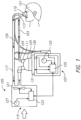
- FIG. 1 shows an example breathing circuit which includes one or more medical tubes.
- a breathing circuit may be a continuous, variable, or bi-level positive airway pressure (PAP) system or other form of respiratory therapy.
- PAP positive airway pressure
- Gases may be transported in the breathing circuit of Figure 1 as follows. Dry or relatively dry gases pass from a gases source 105 to a humidifier 107, which humidifies the dry gases.
- the gases source 105 may be, for example, a ventilator or a blower.
- the humidifier 107 connects to an end 109 of an inspiratory tube 103 via a port 111, thereby supplying humidified gases to the inspiratory tube 103, which may be configured to deliver breathing gases to a patient.
- the gases flow through the inspiratory tube 103 to a Y-piece 113, and then to a patient 101 through a patient interface 115 connected to the Y-piece 113.
- An expiratory tube 117 also connects to the patient interface 115 through the Y-piece 113 and may be configured to move exhaled gases away from the patient 101.
- the expiratory tube 117 returns exhaled gases from the patient 101 to the gases source 105.
- dry or relatively dry gases enter the gases source 105 through a vent 119.
- a fan 121 may improve gas flow into the gases source 105 by drawing air or other gases through the vent 119.
- the fan 121 may be, for instance, a variable speed fan, where an electronic controller 123 controls the fan speed.
- the function of the electronic controller 123 may be controlled by an electronic master controller 125 in response to inputs to the master controller 125 and a user-set predetermined required value (preset value) of pressure or fan speed via a dial 127.
- the humidifier 107 comprises a humidification chamber 129 containing a volume of water 130 or other suitable humidifying liquid.
- the humidification chamber 129 is removable from the humidifier 107 after use to allow the humidification chamber 129 to be more readily sterilized or disposed.
- the body of the humidification chamber 129 may be formed from a non-conductive glass or plastics material, but the humidification chamber 129 may also include conductive components.
- the humidification chamber 129 may include a highly heat-conductive base (for example, an aluminum base) contacting or associated with a heater plate 131 on the humidifier 107.
- the humidifier 107 may also include electronic controls.
- the humidifier 107 includes an electronic, analog, or digital master controller 125.
- the master controller 125 may be a microprocessor-based controller executing computer software commands stored in associated memory.
- the master controller 125 determines when (or to what level) to energize the heater plate 131 to heat the water 130 within the humidification chamber 129.
- Patient interface is a broad term and is to be given its ordinary and customary meaning to a person of ordinary skill in the art (that is, it is not to be limited to a special or customized meaning) and includes, without limitation, masks (such as tracheal mask, face masks, and nasal masks), cannulas, and nasal pillows.
- a temperature probe 135 may connect to the inspiratory tube 103 near the Y-piece 113, or directly to the Y-piece 113 or the patient interface 115. The temperature probe 135 monitors the temperature of the flow of gases near or at the patient interface 115.
- a heating filament (not shown) may be used to adjust the temperature of the patient interface 115, the Y-piece 113, and/or the inspiratory tube 103 to raise the temperature of the flow of gases above the saturation temperature, thereby reducing the opportunity for unwanted condensation.
- exhaled gases are returned from the patient interface 115 to the gases source 105 via the expiratory tube 117.
- the expiratory tube 117 may have a temperature probe and/or heating filament, as described above with respect to the inspiratory tube 103, integrated with it to reduce the opportunity for condensation. Furthermore, the expiratory tube 117 need not return exhaled gases to the gases source 105. Alternatively, exhaled gases may be passed directly to ambient surroundings or to other ancillary equipment, such as an air scrubber/filter (not shown). In certain embodiments, the expiratory tube 117 is omitted altogether.
- the system of Figure 1 may be readily adapted for other applications involving the supply of a heated and/or humidified gas flow to a user or patient, including but not limited to laparoscopy, ventilation, and the like. Such applications may use alternative gases, operating parameters (e.g., flow, pressure, temperature, or humidity) and patient interfaces.
- operating parameters e.g., flow, pressure, temperature, or humidity
- Example embodiments described herein below may be configured for incorporation in the system of Figure 1 , or a similar system, and the further description should be read in combination with the disclosure relating to Figure 1 .
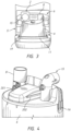
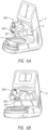
- FIGs 2A and 2B illustrate a humidification apparatus 1 according to an example embodiment.
- the apparatus includes a circuit connector 2 that pneumatically connects a medical tube or conduit 3 to an outlet 15 of a humidification chamber 4.
- the outlet 15 may terminate in a substantially horizontal portion that is angled away from a base unit 5 when the humidification chamber 4 is installed on the base unit 5.
- the conduit 3 may be an inspiratory limb of a patient circuit, i.e., configured to deliver humidified gases to a user, such as via a patient interface (not shown).
- An inlet 8 of the humidification chamber 4 is configured to be fluidly connected to a source of pressurised gas.
- the inlet 8 may be pneumatically coupled to a motorised fan in or associated with the base unit 5 that drives gases through the inlet 8.
- the circuit connector 2 further facilitates electrical connection to the base unit 5 via a coupler 6.
- the coupler 6 may be integrally formed with the base unit 5 or may be a separate, replaceable module or cartridge.
- the ability to change modules may advantageously be used to enable use of different forms of humidification chamber and/or circuit connector. Additionally or alternatively, by comprising control circuitry, the module may be changed to alter the operation of the humidification apparatus 1.
- the conduit 3 may comprise one or more resistive heating wires that provide for heating of gases flowing through the conduit and/or sensor wires that electrically or otherwise facilitate communication of signals relating to one or more parameters of the system.
- the term "electrical connection” is used to distinguish from “pneumatic connection” and should not be construed in a limiting way. For example, light signals via optical fibres may be communicated. Consequently, the circuit connector 2 may more generally communicatively and/or electrically connect the conduit 3 (and any associated peripheral equipment, such as sensors, for example) to the base unit 5, such as via the coupler 6.
- the circuit connector 2 may include at least one button or switch 10, which may be manually depressed to enable the circuit connector 2 (and hence also the conduit 3) to be disconnected from the humidification chamber 4.
- the circuit connector 2 and the outlet 15 of the humidification chamber 4 may become lockably engaged on connection therebetween with the at least one button or switch 10 being used to subsequently allow for disengaging the circuit connector 2 from the humidification chamber 4. Any suitable connection may be used.
- the base unit 5 further includes a panel 9 which may be used to mount a user display and/or controls. For example, various dials, switches, and other input means may be used to control operation of the device. Additionally or alternatively, a touch screen display may be used.
- the user display may display parameters of the system, warnings in the event of any errors or malfunctions, or prompts where user action is required, etc. Where a touch screen display is used, the same display may be used to present information to a user and receive inputs from a user, at least in part.
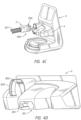
- the base unit 5 includes a heater plate 11 as shown in Figure 3 , which is controllably powered to heat the contents of the humidification chamber 4.
- the humidification chamber 4 may comprise a base plate 19 formed from a highly heat conductive material.
- the two surfaces may be biased towards each other.
- a lip 12 extends outwards from, or proximate to, the base plate 19 of the humidification chamber 4 and is received under a projecting rim 13 of the base unit 5 as the humidification chamber 4 is slid onto the base unit 5.
- the heater plate 11 may be spring mounted such that the heater plate 11 is urged upwards into the base plate 19 of the humidification chamber 4, with the lip 12 acting against the projecting rim 13.
- the base unit 5 further includes a sprung latch bar 14.
- the latch bar 14 is first depressed such that the lip 12 is able to be received under the projecting rim 13. This may be conveniently performed by positioning the base plate 19 of the humidification chamber 4 on the latch bar 14 and pressing the humidification chamber 4 downward and then toward the rear of the base unit 5.
- the latch bar 14 can raise and act as a mechanical stop to prevent unintended removal of the humidification chamber 4 from the base unit 5.
- the latch bar 14 To disengage the humidification chamber 4 from the base unit 5, the latch bar 14 must first be depressed and then the humidification chamber 4 pulled away from the base unit 5 by sliding the base plate 19 of the humidification chamber 4 across the surface of the heater plate 11 and then onto the latch bar 14.
- the humidification chamber 4 may include gripping portions 16 that make it easier for a user to grip the humidification chamber 4 as it is pulled away from the base unit 5.
- the outlet 15 of the humidification chamber 4 may be oriented so as to be substantially parallel to the direction of motion of the humidification chamber 4 as it is slid on or off of the base unit 5, at least at the end of the outlet 15 distal from the humidification chamber 4.
- the circuit connector 2 and the outlet 15 are configured to lockably engage, which prevents separation of the circuit connector 2 from the outlet 15 while the humidification chamber 4 is slid onto the base unit 5.
- the conduit 3 and the humidification chamber 4 may be preassembled for shipping, thereby eliminating one step from the setup process. Irrespective of the order of assembly, electrical or other connections between the conduit 3 and/or the circuit connector 2 to the coupler 6 and/or the base unit 5 may be made as the circuit connector 2 engages with the coupler 6.
- disassembly may be performed in different sequences. More particularly, the circuit connector 2 may firstly be removed from the outlet 15 of the humidification chamber 4, followed by removal of the humidification chamber 4 from the base unit 5. Alternatively, the humidification chamber 4 may be removed from the base unit 5 while the circuit connector 2 is still attached to the outlet 15 of the humidification chamber 4. The latter option may advantageously help reduce the likelihood of a spill of fluids during disassembly and disposal of the consumables from the base unit 5.
- various guides may be provided to control the orientation and/or position thereof relative to one another. More particularly, to enable the humidification chamber 4 to be slid into engagement with the base unit 5 and the coupler 6, various orientation features may be provided on the humidification chamber 4 and/or the coupler 6 such that, particularly when the circuit connector 2 is attached to the outlet 15, the component parts are brought readily and easily into alignment. For example, the humidification chamber 4 is able to be brought into full engagement with the base unit 5 such that the circuit connector 2 is also brought into engagement with the coupler 6.
- circuit connector 2 and/or the coupler 6 may additionally or alternatively include orientation features to help ensure that the circuit connector 2 is connected to the humidification chamber 4 with the circuit connector 2 properly oriented to allow for easy coupling of the circuit connector 2 and the humidification chamber 4 to the base unit 5 and the coupler 6.
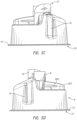
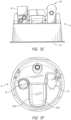
- FIGs 5A to 5F are various alternative views of an example embodiment of the humidification chamber 4.
- Figures 6A to 6C are alternative views of the coupler 6.
- the humidification chamber 4 may include a nose portion 201 and guide wings 202. These features are configured to engage with a contoured recess 301 and slots 302, respectively, in the coupler 6 (see Figures 6A to 6C ).
- a width of the nose portion 201 is defined along the X-axis
- a length of the nose portion 201 is defined along the Y-axis
- a height of the nose portion 201 is defined along the Z-axis.
- the nose portion 201 has a smaller width at a first end than at a second end of the nose portion 201, the first end of the nose portion 201 being configured to be received first in the recess 301. This provides some tolerance as to the position of the humidification chamber 4 along the X-axis (as well as rotationally about the Z-axis), in order for the nose portion 201 to be initially received in the recess 301.
- the wider second end of the nose portion 201 may serve to refine the location of the nose portion 201 (and hence also the humidification chamber 4) along the X-axis (and rotationally about the Z-axis) in that the spacing or tolerance between the nose portion 201 and the recess 301 becomes reduced, thereby reducing the extent of relative movement.
- the recess 301 is configured such that the inclined sidewalls of the nose portion 201 abut corresponding and similarly inclined sidewalls of the recess 301. Having the sidewalls of the nose portion 201 and the sidewalls of the recess 301 configured in this manner controls the position of the humidification chamber 4 not only along the X-axis but also rotationally about the Y- and/or Z-axes, since movement of the nose portion 201 along the X-axis in at least two locations along the length of the nose portion 201, and also along the height of the nose portion 201, is substantially inhibited.
- the sidewalls of the nose portion 201 do not abut the sidewalls of the recess 301.
- the configuration will still assist with initial insertion of the nose portion 201 into the recess 301 and at least significantly restrict movement of the nose portion 201 along the X-axis at the second end of the nose portion 201, although some rotational movement about the Z-axis may be possible.
- the sidewalls of the nose portion 201 are substantially parallel and the recess 301 narrows along its length along the Y-axis from its opening to a width at least as great as that of the nose portion 201.
- the nose portion 201 in combination with the recess 301 may additionally or alternatively provide tolerance along at least the Z-axis with regards to the initial placement of the humidification chamber 4. Further, according to particular embodiments, the nose portion 201 and the recess 301 may cooperate to refine the location of the humidification chamber 4 along the Z-axis and/or rotationally about the X- and/or Y-axes.
- This tolerance is provided in a similar manner to the tolerance in the X-direction.
- the height of the nose portion 201 is lower at the first end than at the second end, the height being measured from the base plate 19.
- the recess 301 is similarly contoured, thereby providing for easy initial insertion followed by the refinement of position along the Z-axis on continued insertion of the humidification chamber 4 into full engagement with the base unit 5.
- the opposing walls of the substantially downwardly facing underside of the recess 301 may not abut along the length thereof with the upwardly facing topside of the nose portion 201.
- one or the other may be orientated to be substantially parallel to the heater plate 11 with similar drawbacks to those mentioned previously. More particularly, while initial insertion may be facilitated, the degree of refinement of the position of the humidification chamber 4 along the Z-axis may be reduced and there may be less control to ensure that the base plate 19 is parallel to the heater plate 11.
- the engagement of the guide wings 202 with the slots 302 provides sufficient movement restriction to reduce the need for alignment and engagement of the base plate 19 with the heater plate 11 via the projecting rim 13.
- the base unit 5 may not include a projecting rim 13.
- the nose portion 201 may be provided in the absence of the guide wings 202.
- the use of the guide wings 202 is preferred, at least in embodiments in which the heater plate 11 is spring mounted, so as to improve control of the positioning of the humidification chamber 4 along at least the Z-axis and/or to ensure that the heater plate 11 is substantially parallel to the base plate 19.
- the guide wings 202 may be provided in the absence of the nose portion 201, but such a configuration is less preferable, since the nose portion 201 may more readily assist in the initial locating of the humidification chamber 4 and also perform the initial coarse adjustment thereof to refine the position, with the possibility of the guide wings 202 then being used to further refine the position of the humidification chamber 4 along the Z-axis and controlling the orientation about at least the X- and Y-axes.
- the guide wings 202 may for example be mounted on a substantially rigid mount that extends vertically from the humidification chamber 4, with the guide wings 202 extending laterally therefrom.
- the substantially rigid mount may be substantially planar, with a generally T-shaped cross-section. However, to increase strength and rigidity, the mount may comprise more substantial element(s) having thickness, but a thickness that does not generally bring the mount into direct contact with the coupler 6.
- the guide wings 202 do not extend right to the first end of the nose portion 201. Instead, they are spaced therefrom, thereby enabling initial engagement between the nose portion 201 and the recess 301 without engagement of the guide wings 202 with the slots 302, this only occurring on continued engagement of the humidification chamber 4 with the base unit 5 after the relative positions between the two have been refined.
- the nose portion 201 may be in the form of a contoured recess and vice versa such that a contoured recess of the humidification chamber 4 receives a nose portion or projection of the coupler 6.
- the guide wings 202 may be substituted with grooves that receive wings or other projections on the coupler 6. Other arrangements that perform the same function may also be used.
- the circuit connector 2 may include a cutout 403 configured to accommodate a substantially vertical portion of the outlet 15. Again, this helps to ensure that the circuit connector 2 is correctly oriented as it is inserted onto the end of the outlet 15 since full insertion is only possible with correct alignment. Further, this arrangement provides for a stronger coupling and allows for electrical connection as will be described below. Again, at least an initial portion of the cutout 403 may be angled or curved such that the first part of the cutout 403 that receives the vertical portion of the outlet 15 is wider than the outlet 15, providing some tolerance as to the required initial alignment. However, where the outlet 15 is generally of a circular cross-section, this may not be required as some tolerance is inherently provided due to the circular shape of the outlet 15.
- the circuit connector 2 may additionally or alternatively include an angled cutout 408 that receives a similarly angled protrusion 409 on the outlet 15. Again this serves to obtain and secure orientation of the circuit connector 2 and the outlet 15 relative to one another.
- guide means may be incorporated in the heater plate 11 and/or the base plate 19 of the humidification chamber 4.
- a ridge in the heater plate 11 may be configured to be received in a slot in the base plate 19 of the humidification chamber 4, or vice versa.
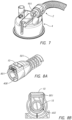
- a first embodiment of the circuit connector 2 is illustrated in Figures 2A, 2B , 6C , and 7 .
- a first end of the circuit connector 2 (see Figure 2B ) is configured to receive and pneumatically seal an end of a respiratory tube or conduit 501 (see Figure 6C ).
- the circuit connector 2 may comprise a main body 502 and an extending portion 504.
- the interior of the main body 502 defines a channel that connects the conduit 501 to the horizontal portion of the outlet 15 to provide a continuous flow passage when assembled.
- a seal e.g., an O-ring, double O-ring, or lip seals
- the coupler 6 is shown including a shroud 505 which receives and covers the extending portion 504. This may help to reduce or eliminate the likelihood of any spilled liquid coming into contact with electrical components of the circuit connector 2 and also serves to strengthen and rigidify the coupling. Further, the shroud 505 may assist in bringing the circuit connector 2 into engagement with the outlet 15 of the humidification chamber 4 and/or into engagement with the base unit 5. More particularly, the shroud 505 provides a visual indication as to where the circuit connector 2 should be positioned. Further, the shroud 505 may provide some physical control over the location of the circuit connector 2. For example, in the embodiment shown, at least the extending portion 504 of the circuit connector 2 is received against a portion of the wall of the shroud 505 opposing the heater plate 11.
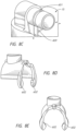
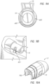
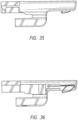
- FIGs 8A to 8C illustrate an embodiment of a lockable but releasable coupling between the circuit connector 2 and the outlet 15.
- the circuit connector 2 includes the button 10 that may be manually actuated such as by a thumb or finger to enable the circuit connector 2 to be removed from the outlet 15.
- the button 10 is formed from a resiliently elastic material and has a portion configured to be received in a recess 601 formed in the outer wall of the outlet 15. Depression of the button 10 disengages an engaging portion of the button 10 from the recess 601.
- Figures 8D and 8E illustrate an alternative embodiment where the button 10 is formed from a substantially rigid material but may be spring mounted. Depression of the button 10 acts against the spring and disengages an engaging portion 602 of the button 10 from recesses in an outer wall of the outlet 15.
- Figures 9A and 9B illustrate an alternative embodiment where the button 10, or at least the engaging portion 602 thereof, is resiliently elastic whereby at least a portion of the button 10 deforms to disengage the engaging portion 602 from recesses 601 in the outlet 15.
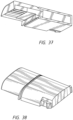
- FIGs 10A to 10H illustrate an alternative embodiment of the circuit connector 2.
- the buttons 10 are positioned on sides of the circuit connector 2, as this may be more convenient in being placed at natural contact points for a user when attempting to disconnect the circuit connector 2 from the outlet 15.
- the buttons 10 are integral with or operably coupled to an elastically deformable ring 701. Depression of the buttons 10 disengages the ring 701 from recesses formed in at least one of the upper and lower outer surfaces of the outlet 15, allowing the circuit connector 2 to be removed.
- Figures 10A to 10H also show a cavity 702 for housing electrical or other connections.
- protrusions 705 may be used in the outlet 15 as shown in cross-section in Figure 10I . This applies to this and other embodiments disclosed herein.
- the top of the ring 701 rests behind (or closer to the base unit 5 than) the protrusion 705.
- the buttons 10 are depressed to deform the ring 701 such that the top of the ring 701 rises above the level of the protrusion 705 and then the circuit connector 2 can be removed from the outlet 15.
- Figures 10J and 10K wherein the electrical terminal is in the form of an edge card 901. Further shown is a groove 902 configured to receive a seal such as an o-ring.
- Example electrical connections 801 are shown in Figures 8A and 8B .
- the electrical connections may be provided in the extending portion 504 of the circuit connector 2 such that they extend beyond the pneumatic connection and electrically and/or communicatively couple to a cooperative connector 802 on the coupler 6 as shown in Figure 6D .
- the electrical and other connections may be formed by blade contacts that are received in respective recesses in the coupler 6 that house contacts for connecting thereto.
- Other connectors such as pins may alternatively be used but blade contacts are advantageous in providing some tolerance in the exact relative positioning of the blades in the recesses. In the embodiment shown, some vertical tolerance is provided for.
- the electrical contacts comprise one or more pogo or spring pin contacts that include spring-mounted pins housed in passages that allow them to vary the extent to which they protrude from the housing, thereby providing tolerance in the relative positions of the circuit connector 2 and the coupler 6 along the axes of the pins. Further, the ability for the pins to become depressed may make insertion of the pins into the apertures that house cooperating or mating connectors easier.
- the electrical connections comprise edge card connectors or card edge connectors, wherein a first part of the connector has one or more conductive tracks provided on a printed circuit board and configured to make contact with one or more pins of a second part of the connector.
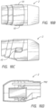
- Figure 11A is a cross-sectional view of an alternate embodiment of the circuit connector 2 engaged with the outlet 15 of the humidification chamber 4.
- the circuit connector 2 has a male connection such that at least a portion of the circuit connector 2 is received inside the outlet 15.
- An o-ring 1005 or other seal is used to seal between the male parts and the inside wall of the outlet 15.
- Figure 11B shows a view similar to that of Figure 11A but modified such that the outlet 15 is configured as the male part that mates with the inner wall of the inlet of the circuit connector 2.
- an o-ring 1005 or other seal may be used to reduce or eliminate the likelihood of leakage.
- the humidification system 2000 may have any suitable configuration.
- the humidification system 2000 may be used in conjunction with other components for supplying heated and/or humidified gases for continuous, variable, or bi-level positive airway pressure (PAP) or any other type of respiratory therapy. It also may be used in conjunction with devices for surgical applications, such as for laparoscopic surgery or the like.
- PAP bi-level positive airway pressure
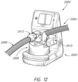
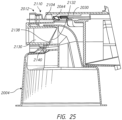
- the illustrated humidification system 2000 comprises a base 2002 that receives a humidification chamber 2004.
- a supply conduit 2006 and a delivery conduit 2008 may be connected to the humidification chamber 2004.
- the supply conduit 2006 may deliver to the humidification chamber 2004 a flow of gases to be humidified.
- the delivery conduit 2008 may deliver to a user or patient the flow of gases after they have been humidified within the chamber 2004.
- the base 2002 includes an electrical connection to one or both of the supply conduit 2006 and the delivery conduit 2008 (e.g., an inspiratory limb).
- the base 2002 comprises a cartridge or coupler 2010.
- the cartridge or coupler 2010 may be integrally formed with the base 2002 or may be a separate, replaceable module or cartridge.
- One or both of the conduits 2006, 2008 may include one or more wires.
- the wires may comprise one or more resistive heating wires that provide for heating of the conduit wall and/or gases flow.
- the wires may comprise one or more sensor wires that facilitate the communication of signals relating to one or more parameters of the system 2000.
- the term "electrical connection" is used in its broadest meaning and should include light signals via fibre optics or the like, for example but without limitation.
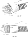
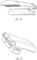
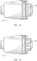
- the illustrated delivery conduit 2008 comprises a connector 2012.
- the connector 2012 facilitates the electrical connection between the conduit 2008 and the cartridge 2010.
- the connector 2012 also facilitates a pneumatic connection between the conduit 2008 and the chamber 2004.
- the connector 2012 facilitates both the electrical connection between the base 2002 (through the cartridge 2010) and the conduit 2008 as well as the pneumatic connection between the chamber 2004 and the conduit 2008.
- the connector 2012 in the illustrated configuration is constructed to connect in a horizontal direction (i.e., a direction parallel to a direction of insertion of the chamber 2004 into or onto the base 2002).
- the connector 2012 is constructed to connect electrically to the cartridge 2010 in the horizontal direction.
- the connector 2012 is constructed to connect pneumatically to the chamber 2004 in the horizontal direction.
- the connector 2012 is constructed to connect to both the cartridge 2010 and the chamber 2004 in the same horizontal direction.
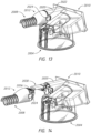
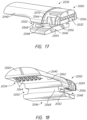
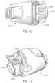
- the cartridge 2010 may include a hood portion 2020 that overlies an electrical connector (e.g., an electrical junction 2034 as shown in Figure 16 ) of the cartridge 2010.
- the hood portion 2020 may extend forward of the base 2002 in a generally horizontal direction.
- the hood portion 2020 may include a recess 2022 along a vertically extending portion.
- the recess 2022 is sized, positioned and configured to receive a portion of the connector 2012 that comprises a release button 2024.
- at least a portion of the hood 2020 extends further along an upper portion of the connector 2012 (when connected to the cartridge 2010) from the base 2002 relative to the location of the release button 2024 on the connector 2012.
- Other configurations are possible.
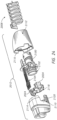
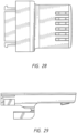
- an insert block 2030 may facilitate the electrical connection between the connector 2012 and the cartridge 2010.
- droplets of water or other moisture may be present on the connector 2012.
- the insert block 2030 helps to isolate the cartridge 2010 from the water or other moisture while facilitating the desired electrical connection between the connector 2012 and the cartridge 2010.
- the insert block 2030 may be mounted to the connector 2012 or to the cartridge 2010. In some configurations, the insert block 2030 is not mounted to either of the connector 2012 or the cartridge 2010. In the illustrated configuration, the insert block 2030 is mounted to the cartridge 2010. By mounting the insert block 2030 to the cartridge 2010, the likelihood of the insert block 2030 becoming misplaced during changing of the conduit 2008 or the like is significantly decreased. By not mounting the insert block 2030 to the connector 2012, changing of the conduit 2008 is simplified and there is less waste as compared to an insert block 2030 that might be discarded with the conduit 2008 following each use.
- the insert block 2030 has a first electrical junction 2032 and a second electrical junction 2034.
- the first electrical junction 2032 is sized, positioned and configured to engage with an electrical connector of the cartridge 2010.
- the second electrical junction 2034 is sized, positioned and configured to engage with electrical contacts 2036 (see Figure 14 ) of the connector 2012.
- the first electrical junction 2032 and the second electrical junction 2034 may be joined together in any suitable manner.
- the insert block 2030 transforms a generally horizontal connection between the first electrical junction 2032 and an electrical connector of the cartridge 2010 into a generally vertical connection between the second electrical junction 2034 and the electrical contacts 2036 of the connector 2012.
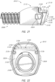
- the insert block 2030 comprises a body 2040.
- the body 2040 is sized and configured to be received within the hood 2020.
- the body 2040 is sized and configured to be retained within the hood 2020.
- the hood 2020 comprises one or more alignment features 2042.
- the alignment features 2042 of the hood 2020 comprise rails 2042.
- the rails 2042 may have any suitable configuration. In the illustrated configuration, two rails 2042 are aligned to each other on diametrically opposed sides of the hood 2020.
- the illustrated cartridge 2010 also comprises a flange 2044.
- the flange 2044 may be integrally formed with the rails 2042 or may be a separate feature from the rails 2042.
- the flange 2044 extends generally horizontally and projects forward from a rear wall of the cavity that receives the connector 2012.
- the flange 2044 is enshrouded by the hood 2020.
- the flange 2044 has a stepped configuration with a distal end having a reduced thickness relative to a proximal end, wherein the proximal end is closer to the rear wall of the cavity than the distal end.
- the body 2040 includes a mounting boss 2046.
- a recess 2048 may be defined between the mounting boss 2046 and another portion of the body 2040 that extends to the first electrical junction 2032.
- the recess 2048 may be sized and configured to receive at least a portion of the flange 2044.
- an engagementportion 2050 of the body 2040 may be spaced apart from the mounting boss 2044 by the recess 2048.
- Other configurations are possible.
- the mounting boss 2044 may include channels 2052.
- the channels 2052 may be sized, positioned and configured to receive the rails 2042.
- the channels 2052 may have a shorter length than the length of the rails 2042 such that a significant portion of the rails 2042 are exposed beyond the mounting boss 2044 when the insert block 2030 has been secured within the hood 2020.
- the engagement portion 2050 of the body 2040 may comprise one or more retention elements 2054.
- the one or more retention elements 2054 may each comprise a deflectable tab.
- At least one deflectable tab 2054 may be positioned on each opposing side of the body 2040.
- the body 2040 has a deflectable tab 2054 disposed on each lateral side of the body 2040.
- the tabs 2054 may include a catch element 2056.
- the catch element 2056 may extend laterally away from the body 2040. In some configurations, the catch element 2056 may extend generally normal from a recess that spaces at least a portion of the deflectable tab 2054 from the body 2040. In some configurations, a proximal portion of the deflectable tab 2054, including the catch element 2056, may be shaped to encourage deflection of the tab 2054 inwardly toward the body 2040 during insertion of the insert block 2030 into the hood 2020. For example, the proximal surface of the catch element 2056 may taper when viewed from the top.
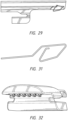
- the body 2040 includes a distal end 2060. Proximally of the distal end 2060, an upper surface of the body 2040 may be shaped to match the inner surface of the hood 2020. In the illustrated configuration, both are curved.
- the distal end 2060 of the body 2040 may be recessed within the hood 2020. As shown in Figure 15 , the distal end 2060 may be shaped and configured to complement an adjoining end of the connector 2012. For example, in the illustrated configuration, the distal end 2060 of the body 2040 may taper slightly.
- a contact surface 2062 may be positioned between the distal end 2060 and the mounting boss 2046. In the illustrated configuration, the contact surface 2062 faces downward. In some configurations, the contact surface 2062 is generally planar.
- the contact surface includes one or more openings through which contact terminals 2064 may extend.
- the contact terminals 2064 may define at least a portion of the second electrical junction 2034.
- the contact terminals 2064 may have any suitable configuration.
- the contact terminals 2064 are sprung terminals that have been configured to minimize or reduce surfaces to which water may adhere. In some configurations, the contact terminals 2064 are sprung terminals that have been configured to minimize or reduce surfaces upon which a cloth may catch during wiping or cleaning. In a relaxed state, the contact terminals 2064 advantageously protrude downward beyond the contact surface 2062. When compressed, the contact terminals 2064 may be at least partially deflected into the body 2040.
- the body 2040 may include an encircling groove 2066.
- the groove 2066 may be positioned rearward of a post 2068 that connects the mounting boss 2046 to the engagement portion 2050.
- the groove 2066 may receive a sealing component 2070.
- the sealing component 2070 may be a seal, an o-ring or the like. In some configurations, neither the groove 2066 nor the sealing component 2070 are present.
- the insert block 2030 may be inserted into the hook 2020.
- the rails 2042 are positioned within the channels 2052.
- the insert block 2030 is slid proximally until the flange 2044 is received within the recess 2048.
- the sealing component 2070 may be compressed between the engagement portion 2050 and the surrounding portions of the cartridge 2010.
- features on an inner surface of the hood 2020 may cause the tabs 2054 to deflect inwardly toward the body 2040 until the catch elements 2056 are proximal of the features on the inner surface, at which point the tabs 2054 may return to a relaxed state with the catch elements 2056 positioned proximally of the features on the inner surface.
- any suitable configuration to secure the insert block 2030 within the hood 202 may be used.
- the first electrical junction 2032 e.g., receptacles
- the second electrical junction 2034 e.g., the terminals 2064
- the terminals 2064 is easily accessed for drying, wiping, cleaning or the like.
- coatings applied to the terminals 2064, or the like water and other liquids are not likely to remain on or adhere to the terminals 2064.
- the connector 2012 may be secured to the end of the conduit 2008 in any suitable manner.
- the connector 2012 generally comprises an inner plug 2100.
- the conduit 2008 may be threaded onto the illustrated inner plug 2100 and secured thereto using overmoulding or any other suitable technique.
- a seal 2102 may be positioned on an outer surface of the inner plug 2100. The seal 2102 may be used to help form a pneumatic seal with an inner surface of a port of the chamber 2004.
- the inner plug 2100 also carries a printed circuit board 2104.
- the printed circuit board 2104 may include contact pads 2106.
- the contact pads 2106 may have any suitable configuration.
- the contact pads 2106 are sized, positioned and configured to be brought into contact with the terminals 2064 of the second electrical junction 2034 of the insert block 2030. In the illustrated configuration, there are six contact pads 2106 that are spaced equally from each other. The contact pads 2106 may be spaced so as to decrease the likelihood of shorting due to the presence of water droplets.
- example embodiments of the connector 2012 may have the contact pads 2106 sized, positioned, and spaced according to various designs.
- Figure 42 shows an example embodiment of the conduit connector 2012, showing the contact pads 2106 uniformly sized and spaced, where the contact pads 2106 are positioned in the order of heater pad, identification pad, sensor pad, sensor pad, identification pad, heater pad (which can be designated HISSIH), each suited for connection to a corresponding wire.
- Figure 43 shows an example embodiment of the conduit connector 2012, showing the contact pads 2106 uniformly spaced, and also in HISSIH order, but with longer heater pads that may help to ensure that the heater wire connections are made before, and broken after, the identification and sensor wire connections.
- Figure 44 shows an example embodiment of the conduit connector 2012, with the contact pads 2106 also having longer heater pads, but with non-uniformly spaced pads in the order SSIIHH, from top to bottom, which increases the space between the sensor pads and the heater pads.
- the first sensor pad (at the top, as illustrated in Figure 44 ) is suited for connection to a positive sensor wire and the second sensor pad is suited for connection to a negative sensor wire, which helps to maximize the space between the positive sensor pad and the heater pads.
- an embodiment of the connector 2012 has the contact pads 2106 in the order SSIIHH, from top to bottom, with longer heater pads and a gap between the heater pads and the other pads, again helping to maximize the space between the heater pads and the sensor pads.
- Figure 48 illustrates a portion of an alternate embodiment of the cartridge 2010, showing the insert block 2030 with the electrical junction or contacts 2034 under the hood portion 2020.
- the electrical contacts 2034 have spacing corresponding to the spacing of the contact pads 2106 of Figure 47 , in particular with a gap between the contacts that correspond to the heater pads and the contacts that correspond to the identification and sensor pads.
- Figures 49 and 50 provide additional views of the alternate embodiment of the insert block 2030 shown in Figure 48 .
- the inner plug 2100 may be retained within a cavity defined within a front cover 2110 and a back cover 2112.
- the front cover 2110 and the back cover 2112 may be coupled together or coupled to the inner plug 2100 to generally enclose the inner plug 2100 within the covers 2110, 2112.
- the back cover 2112 clips onto a portion of the inner plug 2100 and the front cover 2110, and the front cover 2110 also clips onto a portion of the inner plug 2100.
- a seam between the front cover 2110 and the back cover 2112 is obscured by having at least a portion of one of the front cover 2110 and the back cover 2112 overlie a corresponding portion of the other of the two covers 2110, 2112.
- the front cover 2110 includes a recess 2114 over which a lip 2116 of the back cover 2112 slips.
- the lip 2116 obscures the seam between the two covers 2110, 2112 and an abutting relationship between the two covers 2110, 2112 reduces the likelihood of water infiltrating the connector 2012.
- a locking ring 2118 may be secured between the front cover 2110 and the inner plug 2100.
- the locking ring 2118 includes the release buttons 2024.
- the release buttons 2024 protrude through openings 2120 provided in the front cover 2110 and/or the rear cover 2112.
- the locking ring 2118 is configured to latch onto a port of the chamber 2004 and the locking ring 2118 may be deflected by squeezing the release buttons 2024 toward each other, which allows for removal of the locking ring 2118 (and, therefore, the connector 2012) from the port of the chamber 2004.
- the illustrated front cover 2110 has a slightly different configuration from the configuration illustrated in Figure 24 .
- a distal end 2120 of the front cover 2110 may have a sloping face 2122.
- the sloping face 2122 may result from the top portion of the front cover 2110 extend further distally than the bottom portion of the front cover 2110.
- the sloping face 2122 is generally planar.
- the sloping face 2122 may be curvilinear. Other configurations are possible.
- the printed circuit board 2104 may be supported by the front cover 2110.
- the front cover 2110 incorporates a support region 2125 that may be generally surrounded by an outer surface 2124.
- the support region 2125 may underlie the printed circuit board 2104.
- the support region 2125 may provide support to the printed circuit board 2104 to reduce the likelihood of flexure or deflection of the printed circuit board 2104 during connection and use of the connector 2012.
- the support region may comprise one or more ribs or the like.
- the support region comprises a ledge that is formed around a rim that generally encircles the printed circuit board 2104.
- the illustrated ledge is recessed such that the printed circuit board 2104 is either recessed or flush with the surrounding portion of the front cover 2110.
- the one or more ribs may extend under a more central portion of the printed circuit board 2104 and may define supports for at least a central portion of the printed circuit board 2104. Any number of ribs may be used. In some configurations, other forms of support (bosses, plateaus or the like) may be used. In some configurations, no central supports are used.
- the front cover 2110 also comprises at least one channel 2126.
- the front cover 2110 includes two channels 2126.
- the illustrated channels 2126 are generally diametrically opposed.
- the channels 2126 align with and receive the rails 2042 of the hood 2020.
- the channels 2126 may help to align the connector 2012 during coupling with the cartridge 2010.
- the channels 2126 and the rails 2042 also help to resist vertical movement (e.g., up and down), twisting (e.g., rotation relative to the axis of the lumen) and yawing (e.g., rotation relative to an axis normal to the axis of the lumen) of the connector 2012 relative to the cartridge 2010 when the two are coupled together.
- the front cover 2110 comprises a furrow 2128.
- the furrow 2128 extends over at least an upper portion of the front cover 2110.
- the furrow 2128 has a lateral expanse that is at least as great as the width of the printed circuit board 2104 (see Figure 20 ).
- the furrow 2128 helps to divert away from the printed circuit board 2104 liquids that may be spilled onto the connector 2012.
- the furrow 2128 is thus proximal of the printed circuit board 2104 and may be recessed into the front cover 2110 such that at least a lip is defined between the furrow 2128 and the printed circuit board 2104.
- Other configurations are possible.
- the inner plug 2100 defines a lumen 2130.
- the lumen 2130 is in fluid communication with the conduit 2008.
- the lumen 2130 has a distal end 2132.
- the distal end 2132 has a non-normal configuration. In other words, the distal end 2132 is not simply squared off relative to an axis of the lumen 2130.
- the distal end 2132 is configured to complement the inner shape of a port of the humidification chamber 2004 within which it will be inserted.
- the distal end 2132 of the lumen 2130 will slope and extend as far into the port as possible to improve the ability of condensate to drain back into the humidification chamber 2004. This is most clearly shown in Figure 15 .
- the distal end 2132 of the lumen 2130 has a sloping configuration.
- the distal end 2132 of the lumen 2130 slopes at a different slope relative to the sloping face 2122 of the front cover 2110.
- the top of the lumen 2130 projects further distally relative to the bottom of the lumen 2130.
- the top of the lumen 2130 projects forward of a forwardmost portion of the sloping face 2122 of the front cover 2110.
- the top of the lumen 2130 projects further distally than any portion of the front cover 2110.
- the front cover 2110 projects distally of the bottom portion of the lumen 2130 but the top portion of the lumen 2130 projects further distally than the upper portion of the front cover 2110.
- a recess angle R may be defined.
- the recess angle R may be the angle when viewed from the side between the upper portion of the front cover 2110 and the upper portion of the lumen 2130.
- the recess angle R may be 18 degrees in some configurations. It is believed that, if the recess angle R is greater than 18 degrees and if condensate is drained from the conduit 2008 with the connector 2012 upside down (i.e., with the printed circuit board 2104 horizontal and the contact pads 2106 facing the floor), the likelihood of condensate dripping back onto the printed circuit board 2104 is greatly reduced or eliminated.
- the outer support surface 2124 may be flared, i.e., wider at the distal end 2120 than by the furrow 2128. This flaring helps to ensure that the channels 2126 are properly vertically aligned with the rails 2042 during insertion of the connector 2012 under the hood 2020.
- the chamber 2004 includes a port 2138.
- the port 2138 terminates in an opening 2140.
- the distal end 2132 of the lumen 2130 is well within the port 2138 at the time the printed circuit board 2104 approaches contact with the terminals 2064 of the insert block 2030.
- the electrical connection between the printed circuit board 2104 and the insert block 2030 will break before the pneumatic connection between the lumen 2130 and the port 2138 will break. In other words, the electrical connection breaks before the pneumatic connection.
- the pneumatic connection will be established before the electrical connection. More particularly, the lumen 2130 and the port 2138 will mate before the terminals 2064 contact the pads 2106 of the printed circuit board 2104.
Claims (15)
- Kreislaufverbinder (2012) für ein Befeuchtungssystem (2000), wobei das Befeuchtungssystem (2000) eine Basiseinheit (2002) und eine Befeuchtungskammer (2004) umfasst, die Befeuchtungskammer (2004) dazu konfiguriert ist, mit der Basiseinheit (2002) eingriffsfähig zu sein, wobei der Kreislaufverbinder (2012) Folgendes umfasst:einen Einlass, der dazu konfiguriert ist, eine Fluidverbindung mit einem Auslass der Befeuchtungskammer (2004) bereitzustellen, um erwärmte und/oder befeuchtete Gase davon aufzunehmen;einen Auslass, der dazu konfiguriert ist, eine Fluidverbindung mit einer Leitung zum Leiten der erwärmten und/oder befeuchteten Gase zu oder von einem Patienten odereiner anderen Person bereitzustellen; undeinen elektrischen Anschluss, der dazu konfiguriert ist, eine elektrische Verbindung mit einem elektrischen Anschluss der Basiseinheit bereitzustellen,dadurch gekennzeichnet, dass:der elektrische Anschluss sechs freiliegende Kontaktpads (2106) umfasst, die dazu bemessen, positioniert und konfiguriert sind, mit dem elektrischen Anschluss der Basiseinheit in Kontakt gebracht zu werden; unddie sechs freiliegenden Kontaktpads (2106) auf einer Leiterplatte (2104) gebildet sind und die Leiterplatte (2104) von einer äußeren Auflagefläche (2124) gestützt wird.
- Kreislaufverbinder (2012) nach Anspruch 1, wobei die Kontaktpads (2106) alle die gleiche Länge aufweisen.
- Kreislaufverbinder (2012) nach Anspruch 1, wobei die Kontaktpads (2106) nicht alle die gleiche Länge aufweisen.
- Kreislaufverbinder (2012) nach einem der vorangehenden Ansprüche, wobei die Kontaktpads (2106) auf einer Leiterplatte gebildet sind und die Leiterplatte von einer äußeren Auflagefläche gestützt wird, die an einem distalen Ende breiter als an einem proximalen Ende ist.
- Kreislaufverbinder (2012) nach einem der Ansprüche 1, 3 oder 4, wobei:der Kreislaufverbinder einen Ausschnitt umfasst, der dazu konfiguriert ist, einen ersten Abschnitt des Auslasses der Befeuchtungskammer (2004) unterzubringen, wobei der Ausschnitt den Eingriff des Kreislaufverbinders an dem Auslass der Befeuchtungskammer (2004) hemmt oder einschränkt, wenn er nicht richtig zum Unterbringen des ersten Abschnitts durch den Ausschnitt orientiert ist;der Einlass des Kreislaufverbinders (2012) dazu konfiguriert ist, eine Fluidverbindung mit einem zweiten Abschnitt des Auslasses der Befeuchtungskammer (2004) bereitzustellen; undsich der erste Abschnitt des Auslasses im Wesentlichen vertikal von der Befeuchtungskammer (2004) erstreckt und sich der zweite Abschnitt im Wesentlichen horizontal von dem ersten Abschnitt erstreckt, wobei der zweite Abschnitt durch den ersten Abschnitt an die Befeuchtungskammer angefügt ist.
- Kreislaufverbinder (2012) nach Anspruch 5, wobei der Ausschnitt konturiert ist, um eine breitere Öffnung und einen schmäleren Abschluss aufzuweisen, wodurch eine Toleranz für die Orientierung des Kreislaufverbinders (2012) bei anfänglichem Eingriff bereitgestellt wird und die Orientierung bei fortgesetztem Eingriff korrigiert wird, wenn der Kreislaufverbinder (2012) in Richtung des Auslasses der Befeuchtungskammer (2004) gedrückt wird.
- Kreislaufverbinder (2012) nach einem der vorangehenden Ansprüche, wobei der elektrische Anschluss des Kreislaufverbinders (2012) Folgendes umfasst:einen oder mehrere Pins, die dazu konfiguriert sind, im Gebrauch mit einer oder mehreren Leiterbahnen einer Leiterplatte des elektrischen Anschlusses der Basiseinheit in Kontakt zu kommen, odereine Leiterplatte, umfassend eine oder mehrere Leiterbahnen, die dazu konfiguriert sind, im Gebrauch mit einem oder mehreren Pins des elektrischen Anschlusses der Basiseinheit in Kontakt zu kommen.
- Kreislaufverbinder (2012) nach einem der Ansprüche 1 und 5 bis 6, wobei der elektrische Anschluss des Kreislaufverbinders (2012) Folgendes umfasst:eine Edge-Card, die dazu konfiguriert ist, im Gebrauch in einer Edge-Card-Buchse des elektrischen Anschlusses der Basiseinheit aufgenommen zu werden, odereine Edge-Card-Buchse, die dazu konfiguriert ist, im Gebrauch eine Edge-Card des elektrischen Anschlusses der Basiseinheit aufzunehmen.
- Kreislaufverbinder (2012) nach einem der vorangehenden Ansprüche, wobei der elektrische Anschluss des Kreislaufverbinders (2012) elektrisch mit einem oder mehreren Heizungsdrähten und/oder einem oder mehreren Sensordrähten verbunden ist, wobei die Leitung den einen oder die mehreren Heizungsdrähte und/oder den einen oder die mehreren Sensordrähte umfasst.
- Kreislaufverbinder (2012) nach einem der vorangehenden Ansprüche, wobei der elektrische Anschluss 6 in der Reihenfolge SSIIHH angeordnete Kontaktpads umfasst, wobei die Abstände zwischen den Pads SS, SI, II und HH gleichmäßig sind und ein vergrößerter Abstand zwischen den Pads IH bereitgestellt ist, wobei S, I und H Sensor-, Identifikations- bzw. Heizungspads repräsentieren.
- Kreislaufverbinder (2012) nach Anspruch 10, wobei die Heizungspads länger als die Sensorpads und die Identifikationspads sind.
- Kreislaufverbinder (2012) nach einem der vorangehenden Ansprüche, wobei die freiliegenden Kontaktpads (2106) dazu konfiguriert sind, im Gebrauch über dem Einlass (8) des Kreislaufverbinders (2012) positioniert zu sein, wenn sich die freiliegenden Kontaktpads (2106) mit dem elektrischen Anschluss der Basiseinheit in Kontakt befinden.
- Kreislaufverbinder (2012) nach einem der vorangehenden Ansprüche, wobei die freiliegenden Kontaktpads (2106) dazu konfiguriert sind, im Gebrauch horizontal orientiert zu sein.
- Kreislaufverbinder (2012) nach einem der Ansprüche 1 oder 3 bis 13, umfassend einen Ausschnitt in einem Abschnitt des Kreislaufverbinders (2012), wobei der Ausschnitt einen abgewinkelten Vorsprung des Auslasses der Befeuchtungskammer aufnimmt, wenn der Kreislaufverbinder an die Befeuchtungskammer gekoppelt ist.
- Kreislaufverbinder (2012) nach einem der vorangehenden Ansprüche, wobei die sechs freiliegenden Kontaktpads (2106) nicht alle gleichmäßig voneinander beabstandet sind.
Priority Applications (2)
| Application Number | Priority Date | Filing Date | Title |
|---|---|---|---|
| EP23165697.6A EP4223347A3 (de) | 2013-12-20 | 2014-12-19 | Befeuchtungssystemverbindungen |
| HRP20230840TT HRP20230840T1 (hr) | 2013-12-20 | 2014-12-19 | Spojevi sustava ovlaživanja |
Applications Claiming Priority (3)
| Application Number | Priority Date | Filing Date | Title |
|---|---|---|---|
| US201361919485P | 2013-12-20 | 2013-12-20 | |
| US201462059339P | 2014-10-03 | 2014-10-03 | |
| PCT/NZ2014/050024 WO2015093989A1 (en) | 2013-12-20 | 2014-12-19 | Humidification system connections |
Related Child Applications (2)
| Application Number | Title | Priority Date | Filing Date |
|---|---|---|---|
| EP23165697.6A Division EP4223347A3 (de) | 2013-12-20 | 2014-12-19 | Befeuchtungssystemverbindungen |
| EP23165697.6A Division-Into EP4223347A3 (de) | 2013-12-20 | 2014-12-19 | Befeuchtungssystemverbindungen |
Publications (3)
| Publication Number | Publication Date |
|---|---|
| EP3082926A1 EP3082926A1 (de) | 2016-10-26 |
| EP3082926A4 EP3082926A4 (de) | 2017-06-14 |
| EP3082926B1 true EP3082926B1 (de) | 2023-05-17 |
Family
ID=53403191
Family Applications (2)
| Application Number | Title | Priority Date | Filing Date |
|---|---|---|---|
| EP14872055.0A Active EP3082926B1 (de) | 2013-12-20 | 2014-12-19 | Befeuchtungssystemverbindungen |
| EP23165697.6A Pending EP4223347A3 (de) | 2013-12-20 | 2014-12-19 | Befeuchtungssystemverbindungen |
Family Applications After (1)
| Application Number | Title | Priority Date | Filing Date |
|---|---|---|---|
| EP23165697.6A Pending EP4223347A3 (de) | 2013-12-20 | 2014-12-19 | Befeuchtungssystemverbindungen |
Country Status (19)
| Country | Link |
|---|---|
| US (3) | US10828482B2 (de) |
| EP (2) | EP3082926B1 (de) |
| JP (4) | JP6442510B2 (de) |
| CN (7) | CN110947068B (de) |
| AU (4) | AU2014367362B2 (de) |
| BR (3) | BR122017027113B1 (de) |
| CA (3) | CA3176273A1 (de) |
| DE (1) | DE112014005831T5 (de) |
| DK (1) | DK3082926T3 (de) |
| ES (1) | ES2952715T3 (de) |
| FI (1) | FI3082926T3 (de) |
| GB (5) | GB2558085B (de) |
| HR (1) | HRP20230840T1 (de) |
| HU (1) | HUE062413T2 (de) |
| LT (1) | LT3082926T (de) |
| PL (1) | PL3082926T3 (de) |
| PT (1) | PT3082926T (de) |
| RU (2) | RU2661736C1 (de) |
| WO (1) | WO2015093989A1 (de) |
Families Citing this family (28)
| Publication number | Priority date | Publication date | Assignee | Title |
|---|---|---|---|---|
| US11696992B2 (en) | 2005-09-12 | 2023-07-11 | ResMed Pty Ltd | High flow therapy device utilizing a non-sealing respiratory interface and related methods |
| US8522782B2 (en) * | 2005-09-12 | 2013-09-03 | Mergenet Medical, Inc. | High flow therapy device utilizing a non-sealing respiratory interface and related methods |
| US11833301B2 (en) | 2005-09-12 | 2023-12-05 | ResMed Pty Ltd | High flow therapy device utilizing a non-sealing respiratory interface and related methods |
| US11717174B2 (en) | 2005-09-12 | 2023-08-08 | ResMed Pty Ltd | High flow therapy device utilizing a non-sealing respiratory interface and related methods |
| US11497407B2 (en) | 2005-09-12 | 2022-11-15 | ResMed Pty Ltd | High flow therapy device utilizing a non-sealing respiratory interface and related methods |
| US11458270B2 (en) | 2005-09-12 | 2022-10-04 | ResMed Pty Ltd | High flow therapy device utilizing a non-sealing respiratory interface and related methods |
| US11318267B2 (en) | 2006-09-12 | 2022-05-03 | ResMed Pty Ltd | High flow therapy device utilizing a non-sealing respiratory interface and related methods |
| GB2575894A (en) | 2012-04-27 | 2020-01-29 | Fisher & Paykel Healthcare Ltd | Usability features for respiratory humidification system |
| BR122017019835B1 (pt) * | 2013-09-13 | 2023-01-24 | Fisher & Paykel Healthcare Limited | Sistema de umidificação e método de montagem de um sistema de umidificação |
| LT3082926T (lt) * | 2013-12-20 | 2023-08-25 | Fisher & Paykel Healthcare Limited | Drėkinimo sistemos sujungimai |
| US10449319B2 (en) | 2014-02-07 | 2019-10-22 | Fisher & Paykel Healthcare Limited | Respiratory humidification system |
| EP3607988A1 (de) | 2014-06-03 | 2020-02-12 | Fisher & Paykel Healthcare Limited | Strömungsmischer für atemtherapiesysteme |
| US11278689B2 (en) | 2014-11-17 | 2022-03-22 | Fisher & Paykel Healthcare Limited | Humidification of respiratory gases |
| CN108348724A (zh) | 2015-06-16 | 2018-07-31 | 费雪派克医疗保健有限公司 | 用于呼吸辅助系统的适配器以及可用性特征 |
| GB2598223B (en) * | 2015-06-24 | 2022-08-10 | Fisher & Paykel Healthcare Ltd | Breathing assistance apparatus |
| EP3551978B1 (de) | 2016-12-07 | 2022-01-26 | Fisher&Paykel Healthcare Limited | Erfassungsanordnungen für medizinische vorrichtungen |
| WO2019193535A1 (en) * | 2018-04-05 | 2019-10-10 | John Anna | Dual-pressure respiratory assistance device |
| IT201800005588A1 (it) * | 2018-05-22 | 2019-11-22 | Metodo di controllo di un circuito di ventilazione termoregolato. | |
| KR102060182B1 (ko) * | 2018-05-23 | 2019-12-27 | 엘지전자 주식회사 | 스팀발생장치 |
| CN113476712A (zh) * | 2018-08-13 | 2021-10-08 | 费雪派克医疗保健有限公司 | 用于在呼吸支持系统中使用的设备 |
| CN112292170A (zh) * | 2018-10-26 | 2021-01-29 | 北京怡和嘉业医疗科技股份有限公司 | 用于输送呼吸气体的系统和方法 |
| DE102018008493A1 (de) * | 2018-10-30 | 2020-04-30 | Drägerwerk AG & Co. KGaA | Transfereinheit, Beatmungsvorrichtung, Beatmungssystem sowie Verfahren zum Wechsel einer für einen Beatmungsvorgang eines Patienten verwendeten Beatmungsvorrichtung |
| TW202027812A (zh) | 2018-11-05 | 2020-08-01 | 紐西蘭商費雪 & 佩凱爾關心健康有限公司 | 呼吸輔助設備和/或其部件 |
| CN116637264A (zh) * | 2019-04-17 | 2023-08-25 | 瑞思迈私人有限公司 | Cpap系统 |
| EP3996788A4 (de) * | 2019-07-08 | 2023-07-19 | Fisher & Paykel Healthcare Limited | Medizinische schläuche und verbinder für beatmungsschlauchsysteme |
| WO2021010027A1 (ja) * | 2019-07-12 | 2021-01-21 | 株式会社村田製作所 | Cpap装置 |
| DE102020212441A1 (de) | 2020-10-01 | 2022-04-07 | Raumedic Ag | Verfahren zur Fertigung einer Baugruppe aus einem Kunststoff-Schlauchabschnitt mit mindestens einer Schlauch-Drahteinlage und einem Anschluss-Konnektor |
| TW202300193A (zh) | 2021-05-26 | 2023-01-01 | 紐西蘭商費雪 & 佩凱爾關心健康有限公司 | 對呼吸輔助設備的部件的控制 |
Family Cites Families (631)
| Publication number | Priority date | Publication date | Assignee | Title |
|---|---|---|---|---|
| US485127A (en) | 1892-10-25 | Island | ||
| US1154259A (en) | 1913-03-17 | 1915-09-21 | Claus H Light | Hose-coupling. |
| US2073335A (en) | 1935-10-05 | 1937-03-09 | Connell Karl | Breathing tube |
| US2516864A (en) | 1948-08-24 | 1950-08-01 | Gen Electric | Method of making hose from elastomeric composition |
| US2634311A (en) | 1950-01-31 | 1953-04-07 | Ralph E Darling | Composite fluid and electrical connector |
| US2745074A (en) | 1951-01-11 | 1956-05-08 | Ralph E Darling | Electrically equipped oxygen hose |
| US2874722A (en) | 1952-10-06 | 1959-02-24 | Eva F Hamblin | Buoyant, insulated flexible tubing and method of making same |
| US2788936A (en) | 1954-12-21 | 1957-04-16 | Gen Electric | Blower connections for vacuum cleaners |
| US3117596A (en) | 1961-06-07 | 1964-01-14 | Acme Hamilton Mfg Corp | Buoyant flexible hose |
| US3163707A (en) | 1962-12-27 | 1964-12-29 | Ralph E Darling | Non-stretch flexible tube with conductors therein |
| US3283580A (en) | 1963-09-24 | 1966-11-08 | Nanmac Corp | Fast response right angle thermocouple |
| NL150210B (nl) | 1964-09-14 | 1976-07-15 | Polva Nederland Bv | Buigzame strook voor het schroefvormig wikkelen tot een buis. |
| GB1168770A (en) | 1965-12-01 | 1969-10-29 | Texas Instruments Inc | Self-Regulating Heaters. |
| US3394954A (en) | 1966-05-06 | 1968-07-30 | Sarns Inc | Tube coupling for medical appliances |
| JPS4422293Y1 (de) | 1966-06-07 | 1969-09-19 | ||
| US3485237A (en) | 1967-03-20 | 1969-12-23 | Rca Corp | Self-propelling hose |
| US3638926A (en) | 1967-09-27 | 1972-02-01 | Alfred W Melville | Humidification |
| CH489758A (de) | 1968-04-25 | 1970-04-30 | Badertscher Hans | Wasserverdampfer |
| US3582968A (en) | 1968-12-23 | 1971-06-01 | Texas Instruments Inc | Heaters and methods of making same |
| US3588859A (en) | 1969-04-21 | 1971-06-28 | Frank Petree | Level detector |
| AT312154B (de) | 1969-07-01 | 1973-12-27 | Hans Hirtz | Inhaliergerät zum Behandeln der Atmungswege mit Warmluft |
| US3582094A (en) | 1970-02-16 | 1971-06-01 | Greene Tweed & Co Inc | Sealing assembly |
| US3659604A (en) | 1970-03-30 | 1972-05-02 | Fisher & Paykel | Humidifying means |
| US3766914A (en) | 1970-07-29 | 1973-10-23 | H Jacobs | High pressure resuscitating and ventilating system incorporating humidifying means for the breathing mixture |
| US3703892A (en) | 1970-12-09 | 1972-11-28 | Edward F Meyers | Disposable, retractable thermometer jacket |
| SU379270A1 (ru) | 1971-02-01 | 1973-04-20 | Дозатор наркотических веществ | |
| US3777298A (en) | 1971-12-02 | 1973-12-04 | Empire Prod Inc | Electrical connector |
| DE2308418B2 (de) | 1972-06-21 | 1976-04-08 | Petzetakis, Aristovoulos George, Moschaton, Piräus (Griechenland) | Verfahren und vorrichtung zum herstellen eines insbesondere grosskalibrigen rohres aus thermoplastischem kunststoff |
| US4033808A (en) | 1972-06-21 | 1977-07-05 | Aristovoulos George Petzetakis | Apparatus for the production of hollow bodies, especially large-diameter ducts from thermoplastic synthetic resin |
| US4060576A (en) | 1972-09-13 | 1977-11-29 | Graham Cameron Grant | Method and apparatus for vapor saturated gas delivery |
| US4051205A (en) | 1972-09-13 | 1977-09-27 | Graham Cameron Grant | Apparatus for saturated gas delivery |
| GB1364127A (en) | 1972-12-11 | 1974-08-21 | Cape Eng Co Ltd | Humidifier |
| US3914349A (en) | 1973-04-23 | 1975-10-21 | Sunbeam Corp | Portable humidifier |
| US3954920A (en) | 1973-09-04 | 1976-05-04 | Parkland International Inc. | Gas humidification system |
| GB1490974A (en) | 1973-11-12 | 1977-11-09 | Fodor I | Air humidifiers |
| NL7414546A (nl) | 1973-11-15 | 1975-05-20 | Rhone Poulenc Sa | Soepele verwarmingsbuis en werkwijze voor het vervaardigen ervan. |
| US3903742A (en) | 1974-02-06 | 1975-09-09 | J Tec Ass Inc | Disposable respiratory parameter sensor |
| US4028444A (en) | 1974-03-25 | 1977-06-07 | Chemetron Corporation | Humidifier and automatic control system therefor |
| DE2436406C2 (de) | 1974-07-29 | 1986-04-03 | Volker O. Prof. Dr.Med. 8012 Ottobrunn Lang | Vorrichtung zum Anfeuchten und Erwärmen von Gasen, vorzugsweise von Atemgasen in Respiratoren |
| US3963856A (en) | 1974-11-25 | 1976-06-15 | Steward Plastics, Inc. | Flexible, corrugated, plastic tubing having conductive helical bead |
| US4110419A (en) | 1975-04-18 | 1978-08-29 | Respiratory Care, Inc. | High-volume disposable and semi-disposable cartridge humidifier with self-contained cartridge sterilizing means, and related method |
| US4013122A (en) | 1975-05-05 | 1977-03-22 | Richard William Long | Diver's gas heater |
| US3987133A (en) | 1975-09-05 | 1976-10-19 | Fisher Scientific Company | Humidifier |
| US3990727A (en) | 1976-01-26 | 1976-11-09 | Stephen Franics Gallagher | Quick detachable coupler |
| CH597997A5 (de) | 1976-02-24 | 1978-04-28 | Lpa Les Produits Associes | |
| DE2609034B2 (de) | 1976-03-05 | 1981-04-30 | Drägerwerk AG, 2400 Lübeck | Anschluß für Atemgerät |
| US4172709A (en) | 1976-03-23 | 1979-10-30 | Becton, Dickinson And Company | Bacteria filters with transparent housings |
| US4139762A (en) | 1977-02-22 | 1979-02-13 | Pohrer Harry H | Humidifier |
| SU768402A1 (ru) * | 1978-03-31 | 1980-10-07 | Всесоюзный Научно-Исследовательский Институт Медицинского Приборостроения | Увлажнитель |
| GB2056611B (en) | 1979-08-16 | 1984-01-25 | Dayco Corp | Vacuum cleaner hose assembly and method of making same |
| US4183248A (en) | 1978-08-08 | 1980-01-15 | Rwb Labs | Fast response electronic thermometer probe |
| US4172105A (en) | 1979-02-15 | 1979-10-23 | Respiratory Care, Inc. | Pediatric cartridge humidifier |
| FR2464819A1 (fr) | 1979-09-10 | 1981-03-20 | Pont A Mousson | Tube en matiere plastique obtenu par enroulement en helice d'un profile |
| JPS56109189U (de) | 1980-01-18 | 1981-08-24 | ||
| US4463593A (en) | 1980-11-11 | 1984-08-07 | G. D. Searle & Co. | Apparatus for monitoring the partial pressure of gases |
| US4333451A (en) | 1980-12-12 | 1982-06-08 | Paluch Bernard R | Positive pressure breathing apparatus with condensate removal |
| US4428403A (en) | 1980-12-19 | 1984-01-31 | Extracorporeal Medical Specialties, Inc. | Conduit having spirally wound monofilament material |
| DE3110903A1 (de) | 1981-03-20 | 1982-09-30 | Hospital Engineering GmbH, 7204 Wurmlingen | Vorrichtung zum anschliessen von versorgungsleitungen fuer krankenhaeuser, insbesondere operationssaele und intensivstationen |
| WO1982003548A1 (en) | 1981-04-24 | 1982-10-28 | Sullivan Colin Edward | Device for treating snoring sickness |
| US4430994A (en) | 1981-05-11 | 1984-02-14 | Clawson Burrell E | Respiratory gas heating and humidifying methods and apparatus |
| JPS5844583U (ja) | 1981-09-18 | 1983-03-25 | 金尾 史朗 | 合成樹脂製コルゲ−ト二重管 |
| US4553023A (en) | 1981-11-27 | 1985-11-12 | Nordson Corporation | Thermally insulated electrically heated hose for transmitting hot liquids |
| US4507707A (en) | 1981-12-30 | 1985-03-26 | Willis John G | Electro-pneumatic assembly device |
| US4574188A (en) | 1982-04-16 | 1986-03-04 | Raychem Corporation | Elongate electrical assemblies |
| US4473923A (en) | 1982-05-10 | 1984-10-02 | Dayco Corporation | Vacuum cleaning tool adapter with electrical control means |
| US4500480A (en) | 1982-08-23 | 1985-02-19 | Respiratory Care, Inc. | Pediatric cartridge humidifier |
| US4564748A (en) | 1982-10-29 | 1986-01-14 | Respiratory Care, Inc. | Variable temperature heating control system for inhalation therapy apparatus |
| DE3246247A1 (de) | 1982-12-14 | 1984-06-14 | Siemens AG, 1000 Berlin und 8000 München | Doppelwandiger, flexibler schlauch |
| DE3311811A1 (de) | 1983-03-31 | 1984-10-04 | Hirtz & Co, 5000 Köln | Vorrichtung zum behandeln der atmungswege mit warmluft |
| US4597917A (en) | 1983-04-19 | 1986-07-01 | Lunsford Kevin S | Portable medical gas warming system |
| US4753758A (en) | 1983-05-19 | 1988-06-28 | Intertech Resources Inc. | Respiratory humidifier |
| US4490575A (en) | 1983-05-26 | 1984-12-25 | Automation Industries, Inc. | Flexible hose with external sheathed electrical conductor |
| DE3478900D1 (en) | 1983-11-08 | 1989-08-17 | Bunnell Life Systems Inc | Humidifier, particularly for pulmonary assistance systems |
| US4545290A (en) | 1983-12-23 | 1985-10-08 | Tol-O-Matic, Inc. | Pressure cylinder |
| FR2557318A1 (fr) | 1983-12-26 | 1985-06-28 | A2F | Dispositif electronique assurant une interface universelle entre des capteurs et un appareil de saisie et de traitement des signaux en provenance de ces capteurs |
| US4529867A (en) | 1984-02-09 | 1985-07-16 | Inspiron Corporation | Humidifier and heater |
| JPS60159931U (ja) | 1984-04-02 | 1985-10-24 | シャープ株式会社 | 加湿器 |
| US4684786A (en) | 1984-08-01 | 1987-08-04 | Navistar International Corporation | Electrically heated fuel pick-up assembly for vehicle fuel tanks |
| CA1222300A (en) | 1984-08-21 | 1987-05-26 | Her Majesty The Queen, In Right Of Canada, As Represented By The Minister Of National Defence | Computer controlled constant concentration and size particulate aerosol generation system |
| US4621632A (en) | 1984-11-01 | 1986-11-11 | Bear Medical Systems, Inc. | Humidifier system |
| US4676237A (en) | 1985-01-29 | 1987-06-30 | Boutade Worldwide Investments Nv | Inhaler device |
| GB2173274B (en) | 1985-04-04 | 1989-02-01 | Boc Group Plc | Improvements in inhalation apparatus |
| GB8510805D0 (en) | 1985-04-29 | 1985-06-05 | Penlon Ltd | Vaporizing apparatus |
| AU581986B2 (en) | 1985-05-22 | 1989-03-09 | Fisher & Paykel Healthcare Limited | Improvements in or relating to methods of and/or apparatus for humidifying gases |
| GB2176313A (en) | 1985-06-07 | 1986-12-17 | Fraser Sweatman Ind Inc | Apparatus and method for controlling and monitoring mixing of two or more gases |
| US4722334A (en) | 1985-07-16 | 1988-02-02 | Transpirator Technologies, Inc. | Method and apparatus for pulmonary and cardiovascular conditioning of racehorses and competition animals |
| JPS6265401A (ja) | 1985-09-18 | 1987-03-24 | 安田 繁之 | 感熱電気抵抗組成物における定常発熱温度の調整方法 |
| DE3629916A1 (de) | 1986-01-21 | 1987-07-23 | Venta Gmbh | Vorrichtung zur reinigung und/oder be- und entfeuchtung von gasen, insbesondere luft |
| JPH025799Y2 (de) | 1986-02-07 | 1990-02-13 | ||
| DE3618614A1 (de) | 1986-06-03 | 1987-12-10 | Draegerwerk Ag | Waermetauscher fuer angefeuchtete atemluft |
| BE905330A (nl) | 1986-08-26 | 1986-12-16 | Anthony Jean M | Inrichting om lucht of medische gassen in een geconditioneerde toestand, inz. bevochtigd en/of verwarmd aan een patient toe te dienen. |
| DE3629353C1 (en) | 1986-08-28 | 1988-01-07 | Draegerwerk Ag | Ventilation device |
| JPS6365845A (ja) | 1986-09-05 | 1988-03-24 | ミノルタ株式会社 | オキシメ−タ装置 |
| JPH0751126B2 (ja) | 1986-12-05 | 1995-06-05 | 住友電気工業株式会社 | 経皮血中ガスセンサ |
| US4813280A (en) | 1987-04-01 | 1989-03-21 | The Dow Chemical Company | Thermal pulse flow meter with disposable cell |
| DE3716653A1 (de) | 1987-05-19 | 1988-12-08 | Draegerwerk Ag | Stoffaustauschsystem, insbesondere zur befeuchtung von gasen |
| DE3717418C1 (de) | 1987-05-23 | 1988-10-06 | Baston Artur Vobau | Zylindrischer Hohlkoerper aus schraubenlinienfoermig aufgewickeltem Kunststoffprofil |
| FR2617943B1 (fr) | 1987-07-06 | 1990-10-05 | Inventa Ag | Raccord rapide destine a relier une conduite flexible ou rigide |
| US4941469A (en) | 1987-11-12 | 1990-07-17 | Carmeli Adahan | Portable ventilator apparatus |
| US4861523A (en) | 1987-07-13 | 1989-08-29 | Beran Anthony V | Humidification in respiratory systems |
| US5092326A (en) | 1987-11-19 | 1992-03-03 | Winn Bryan D | Apparatus and method for a ventilator system |
| US4921642A (en) | 1987-12-03 | 1990-05-01 | Puritan-Bennett Corporation | Humidifier module for use in a gas humidification assembly |
| US4830515A (en) | 1987-12-28 | 1989-05-16 | Omega Engineering, Inc. | Mounting clip for a thermocouple assembly |
| US4911157A (en) | 1988-01-07 | 1990-03-27 | Pegasus Research Corporation | Self-regulating, heated nebulizer system |
| US4829997A (en) | 1988-02-18 | 1989-05-16 | University Of Victoria | Portable heat exchanger for inhalation rewarming |
| US4829998A (en) | 1988-02-25 | 1989-05-16 | Jackson Richard R | Delivering breathable gas |
| US4911357A (en) | 1988-04-11 | 1990-03-27 | Shibaura Electronics Company, Ltd. | Humidity controller utilizing absolute humidity |
| GB8811933D0 (en) | 1988-05-20 | 1988-06-22 | Smiths Industries Plc | Ducting |
| JPH0610552B2 (ja) * | 1988-07-08 | 1994-02-09 | アトム株式会社 | 加湿器 |
| FI82133C (sv) | 1988-08-17 | 1991-01-10 | Kwh Pipe Ab Oy | Spirallindat rör |
| NZ226784A (en) | 1988-09-29 | 1992-10-28 | Fisher & Paykel | Gas humidifier with microporous wall |
| US4911559A (en) | 1988-11-01 | 1990-03-27 | Diatek, Inc. | Disposable probe cover assembly for medical thermometer |
| US4967744A (en) | 1988-11-03 | 1990-11-06 | Airoflex Medical, Inc. | Flexible breathing circuit |
| US5164652A (en) | 1989-04-21 | 1992-11-17 | Motorola, Inc. | Method and apparatus for determining battery type and modifying operating characteristics |
| US5058588A (en) | 1989-09-19 | 1991-10-22 | Hewlett-Packard Company | Oximeter and medical sensor therefor |
| US5060506A (en) | 1989-10-23 | 1991-10-29 | Douglas David W | Method and apparatus for monitoring the content of binary gas mixtures |
| US5101820A (en) | 1989-11-02 | 1992-04-07 | Christopher Kent L | Apparatus for high continuous flow augmentation of ventilation and method therefor |
| JPH03194747A (ja) | 1989-12-22 | 1991-08-26 | Kyocera Corp | 磁界変調光磁気記録用磁気ヘッド |
| US5148801A (en) | 1990-03-23 | 1992-09-22 | University Of Victoria | Electronic heater-humidifier for hypothermia treatment |
| US5224923A (en) | 1990-03-26 | 1993-07-06 | Air-Shields, Inc. | Infant incubator |
| BR9101157A (pt) | 1990-03-26 | 1991-11-05 | Air Shields | Umedecedor de incubadeira para recem-nascidos |
| US5031612A (en) | 1990-04-24 | 1991-07-16 | Devilbiss Health Care, Inc. | System and method for delivering warm humidified air |
| DE4020522A1 (de) | 1990-06-28 | 1992-01-09 | Fresenius Ag | Medizinisches geraetesystem |
| US5230331A (en) | 1990-07-19 | 1993-07-27 | R. J. Instruments | Hot wire anemometer adapted for insertion in a calibration socket of a pulmonary gas flow monitor |
| US5117819A (en) | 1990-09-10 | 1992-06-02 | Healthdyne, Inc. | Nasal positive pressure device |
| IT1243853B (it) | 1990-10-19 | 1994-06-28 | Hospital Hi Tec S R L | Apparecchiatura per la respirazione a pressione positiva continua alveolare. |
| DE4034611A1 (de) | 1990-10-31 | 1992-05-07 | Stiebel Eltron Gmbh & Co Kg | Elektrischer durchlauferhitzer |
| US5134996A (en) | 1991-01-09 | 1992-08-04 | Smiths Industries Medical Systems, Inc. | Inspiration and expiration indicator for a suction catheter |
| DE4102223A1 (de) | 1991-01-23 | 1992-07-30 | Peter Dr Sc Techn Schaller | Patientenschlauch-heizung eines beatmungsgeraetes |
| US5720293A (en) | 1991-01-29 | 1998-02-24 | Baxter International Inc. | Diagnostic catheter with memory |
| US5197895A (en) | 1991-05-10 | 1993-03-30 | Bicore Monitoring Systems | Disposable electro-fluidic connector with data storage |
| US5529060A (en) | 1991-05-22 | 1996-06-25 | Fisher & Paykel Limited | Humidifiers with control systems to prevent condensation |
| US5630806A (en) | 1991-08-13 | 1997-05-20 | Hudson International Conductors | Spiral wrapped medical tubing |
| US5213376A (en) | 1991-09-03 | 1993-05-25 | Itt Corporation | Squeeze-to-release quick connector |
| SE503089C2 (sv) | 1991-09-20 | 1996-03-25 | Gibeck Respiration Ab | Anordning för anslutning av en patient till en respirator innefattande en fuktvärmeväxlare samt användning av en fuktvärmeväxlare i denna anordning |
| GB2260003B (en) | 1991-09-28 | 1995-06-14 | Motorola Israel Ltd | Option board identification |
| EP0535952B1 (de) | 1991-10-04 | 1997-12-29 | FISHER & PAYKEL LIMITED | Luftbefeuchter |
| DE4133235A1 (de) | 1991-10-07 | 1993-04-08 | Draegerwerk Ag | Geblaeseunterstuetztes atemschutzgeraet mit einem aufsetzbaren steuerteil |
| JP3463303B2 (ja) | 1991-12-27 | 2003-11-05 | 日産自動車株式会社 | 車両用ヒートポンプ式冷暖房装置 |
| DE4244493A1 (de) | 1992-01-18 | 1993-07-22 | Eilentropp Hew Kabel | |
| DE9200567U1 (de) | 1992-01-18 | 1992-07-02 | Hew - Kabel Heinz Eilentropp Kg, 5272 Wipperfuerth, De | |
| US5231979A (en) | 1992-02-14 | 1993-08-03 | Puritan-Bennett Corporation | Humidifier for CPAP device |
| AU3713193A (en) | 1992-04-24 | 1993-10-28 | Fisher & Paykel Limited | Humidifier apparatus and/or gases distribution chambers and/or temperature probes for the same |
| FI95219C (sv) | 1992-04-30 | 1996-01-10 | Kwh Pipe Ab Oy | Svetsningsförfarande vid framställning av spirallindat rör och svetshuvud för utförande av förfarandet |
| JP2654887B2 (ja) | 1992-05-22 | 1997-09-17 | 将秀 大塚 | 結露センサー付加温加湿器 |
| JPH0623051A (ja) | 1992-07-06 | 1994-02-01 | Toransumedo Kk | 加温加湿装置 |
| US5307243A (en) | 1992-10-30 | 1994-04-26 | Square D Company | Wire management assembly for an electrical distribution housing |
| DE4242154C2 (de) | 1992-12-14 | 1995-04-20 | United Carr Gmbh Trw | Verschlußdeckel |
| US5347211A (en) | 1993-03-11 | 1994-09-13 | Innova Electronics Corporation | Selectable output power converter |
| US5544275A (en) | 1993-03-17 | 1996-08-06 | Applied Materials, Inc. | Electrically heated fluid carrying conduit having integrated heating elements and electrical conductors |
| IT229819Y1 (it) | 1993-04-19 | 1999-02-05 | Dar Spa | Struttura di tubo spiralato per apparecchiature di ventilazione artificiale di pazienti |
| US5389004A (en) | 1993-04-23 | 1995-02-14 | Electrolux Corporation | Handle and wand system for vacuum cleaner |
| US5448447A (en) | 1993-04-26 | 1995-09-05 | Cabot Corporation | Process for making an improved tantalum powder and high capacitance low leakage electrode made therefrom |
| GB9309294D0 (en) | 1993-05-06 | 1993-06-16 | Smiths Ind Public Ltd | Heaters and heated devices |
| DE4318534C2 (de) | 1993-06-03 | 1996-07-11 | United Carr Gmbh Trw | Haltedübel |
| US5388443A (en) | 1993-06-24 | 1995-02-14 | Manaka; Junji | Atmosphere sensor and method for manufacturing the sensor |
| US5392770A (en) | 1993-06-29 | 1995-02-28 | Clawson; Burrell E. | Tubing circuit systems for humidified respiratory gas |
| US5342126A (en) | 1993-07-09 | 1994-08-30 | General Motors Corporation | Twist lock attachment for a thermal probe |
| US5346128A (en) | 1993-07-22 | 1994-09-13 | Honeywell Inc. | Humidity control system |
| TW270248B (de) | 1993-11-17 | 1996-02-11 | Whitaker Corp | |
| GB2284356B (en) | 1993-11-22 | 1997-10-29 | Fisher & Paykel | Respiratory humidifier conduit |
| US5449234A (en) | 1993-11-29 | 1995-09-12 | Caterpillar Inc. | Air temperature sensor |
| US5759149A (en) | 1993-12-17 | 1998-06-02 | Hill-Rom, Inc. | Patient thermal support device |
| DE4403950B4 (de) | 1994-02-08 | 2007-03-01 | Vorwerk & Co. Interholding Gmbh | Stecker-Adapter |
| US5600752A (en) | 1994-03-11 | 1997-02-04 | Industrial Design Laboratories, Inc. | Flexible gas hose assembly with concentric helical tube members having reinforcement spring coils |
| US5640951A (en) | 1994-03-15 | 1997-06-24 | Fisher & Paykel Limited | Humidifier conduit |
| US5454061A (en) | 1994-05-27 | 1995-09-26 | Steward Plastics, Inc. | Apparatus and method for making flexible tubing with helically wound heating conductor |
| US5848223A (en) | 1994-05-27 | 1998-12-08 | Steward Plastics, Inc. | Double-walled flexible tubing product with helical support bead and heating conductor and apparatus and method for making |
| DE9409231U1 (de) | 1994-06-07 | 1994-11-03 | Madaus Schwarzer Medtech | Beatmungsgerät für die Schlafmedizin |
| JPH0861731A (ja) | 1994-08-24 | 1996-03-08 | Matsushita Electric Ind Co Ltd | 給排気装置 |
| DE19534001B4 (de) | 1994-09-20 | 2006-05-18 | Fisher & Paykel, East Tamaki | Befeuchterkammer |
| US5516466A (en) | 1994-10-27 | 1996-05-14 | Armstrong International, Inc. | Steam humidifier system |
| SE503771C2 (sv) | 1994-12-01 | 1996-09-02 | Gibeck Respiration Ab | Anordning vid fukt-värmeväxlare |
| US5483616A (en) | 1994-12-21 | 1996-01-09 | Duracraft Corporation | Humidifier tank with improved handle |
| IT1272859B (it) | 1995-01-03 | 1997-07-01 | Dar Spa | Struttura di tubo di ventilazione perticolarmente per apparecchi medicali |
| GB9503012D0 (en) | 1995-02-16 | 1995-04-05 | Smiths Industries Plc | Humidifier systems |
| DE29504734U1 (de) | 1995-03-20 | 1996-07-18 | Perycut Chemie Ag | Verdampfervorrichtung |
| US5667306A (en) | 1995-04-27 | 1997-09-16 | Montreuil; Richard | Numerical temperature reading apparatus for spa, swimming pool and whirlpool |
| US5564415A (en) | 1995-06-07 | 1996-10-15 | Lifecare International, Inc. | Humidifier for a ventilator |
| US5988164A (en) | 1995-07-31 | 1999-11-23 | Paluch; Bernard | Breathing circuits with humidity controls |
| US6024694A (en) | 1995-09-25 | 2000-02-15 | Hill-Rom, Inc. | Humidifier for a thermal support apparatus |
| EP0873148A4 (de) | 1995-11-13 | 1999-12-29 | Fisher & Paykel | Beheiztes beatmungsrohr |
| US5660567A (en) | 1995-11-14 | 1997-08-26 | Nellcor Puritan Bennett Incorporated | Medical sensor connector with removable encoding device |
| US5630752A (en) | 1995-12-11 | 1997-05-20 | Gubash; Peter J. | Low profile air vent for slanted roof |
| JPH09234247A (ja) | 1995-12-27 | 1997-09-09 | Nikkiso Y S I Kk | 人工呼吸装置および改良された加温加湿装置 |
| DE69630395T2 (de) | 1995-12-28 | 2004-08-05 | Omron Healthcare Co., Ltd. | Infrarotthermometer |
| DE19604201A1 (de) | 1996-02-06 | 1997-08-07 | Braun Ag | Schutzkappe |
| DE19608675C2 (de) | 1996-03-06 | 1999-07-29 | Delphi Automotive Systems Gmbh | Temperaturmeßvorrichtung mit einer medienführenden Rohrleitung |
| CN2243015Y (zh) | 1996-03-15 | 1996-12-18 | 许建新 | 密封型可伸缩金属软管 |
| JPH09276408A (ja) | 1996-04-11 | 1997-10-28 | Sanyo Denshi Kogyo Kk | 呼吸用気体供給装置 |
| DE19621541C1 (de) | 1996-05-29 | 1997-04-10 | Draegerwerk Ag | Beatmungsanfeuchter |
| US6219490B1 (en) | 1996-06-13 | 2001-04-17 | Mallinckrodt Inc. | Ventilation tube, particularly for medical devices |
| IT240734Y1 (it) | 1996-06-13 | 2001-04-11 | Mallinckrodt Medical S P A | Struttura di tubo di ventilazione particolarmente per apparecchimedicali |
| JPH1028737A (ja) | 1996-07-16 | 1998-02-03 | Metoran:Kk | 加湿調整ユニット、人工呼吸器用加湿器及び加湿調整ユニットの製造方法 |
| DE19647548C2 (de) | 1996-11-16 | 1999-05-20 | Bgm Buerk Ges Fuer Vertrieb Un | Medizinische Vorrichtung zur Beheizung eines Atemgases |
| US5778872A (en) | 1996-11-18 | 1998-07-14 | Medlis, Inc. | Artificial ventilation system and methods of controlling carbon dioxide rebreathing |
| CA2222830C (en) | 1996-12-02 | 2004-03-30 | Fisher & Paykel Limited | Humidifier sleep apnea treatment apparatus |
| AUPO425496A0 (en) | 1996-12-18 | 1997-01-16 | William A Cook Australia Pty Ltd | Medical humidifier |
| US6053482A (en) | 1997-01-31 | 2000-04-25 | Holmes Products Corp. | Humidifier including a water filtration device |
| JPH10223303A (ja) | 1997-02-06 | 1998-08-21 | Yazaki Corp | 防水コネクタ用ゴム栓 |
| US5993259A (en) | 1997-02-07 | 1999-11-30 | Teradyne, Inc. | High speed, high density electrical connector |
| US5943473A (en) | 1997-05-29 | 1999-08-24 | Levine; Walter | Heated cartridge humidifier |
| US6402207B1 (en) | 1997-06-09 | 2002-06-11 | Qd Enterprises, Llc | Safety indexed medical connectors |
| EP2143459B1 (de) | 1997-06-17 | 2013-08-14 | Fisher & Paykel Healthcare Limited | Befeuchtungssystem für einen Respirator |
| CA2621113C (en) | 1997-06-17 | 2011-10-11 | Fisher & Paykel Healthcare Limited | Respiratory humidification system |
| AU746572C (en) | 1997-06-17 | 2004-07-01 | Fisher & Paykel Healthcare Limited | Respiratory humidification system |
| US20040221844A1 (en) | 1997-06-17 | 2004-11-11 | Hunt Peter John | Humidity controller |
| AUPO742297A0 (en) | 1997-06-18 | 1997-07-10 | Resmed Limited | An apparatus for supplying breathable gas |
| USD419522S (en) | 1997-06-19 | 2000-01-25 | Thomas & Betts International, Inc. | Four position two-piece battery block connector assembly |
| US6189870B1 (en) | 1997-07-01 | 2001-02-20 | Gordon Withall | Dual port medical oxygen humidifier |
| JPH1133119A (ja) | 1997-07-18 | 1999-02-09 | Frontier:Kk | 呼吸回路 |
| FR2766547B1 (fr) | 1997-07-24 | 1999-09-17 | Gessil | Conduit flexible, par exemple tuyau a usage medical ou chirurgical |
| DE19739472A1 (de) | 1997-09-09 | 1999-03-18 | Freudenberg Carl Fa | Dichtungsanordnung |
| US5938624A (en) | 1997-09-10 | 1999-08-17 | Radi Medical Systems Ab | Male connector with a continous surface for a guide wire and method therefor |
| US6306235B1 (en) | 1997-10-16 | 2001-10-23 | Nomaco, Inc. | Spiral formed products and method of manufacture |
| US6138674A (en) | 1997-10-16 | 2000-10-31 | Datex-Ohmeda, Inc. | Active temperature and humidity compensator for anesthesia monitoring systems |
| US6078729A (en) | 1997-10-21 | 2000-06-20 | National Environmental Products Ltd., Inc. | Foam, drain and fill control system for humidifier |
| US6125847A (en) | 1997-10-22 | 2000-10-03 | Lin; Chung-Yuan | Anesthetic applicator with a temperature humidity regulating capability |
| US6039696A (en) | 1997-10-31 | 2000-03-21 | Medcare Medical Group, Inc. | Method and apparatus for sensing humidity in a patient with an artificial airway |
| US6126610A (en) | 1997-11-03 | 2000-10-03 | Novametrix Medical Systems, Inc. | Pneumatic connector with encoding |
| US6594366B1 (en) | 1997-12-02 | 2003-07-15 | Siemens Information & Communication Networks, Inc. | Headset/radio auto sensing jack |
| NL1007699C2 (nl) | 1997-12-04 | 1999-06-09 | Medisize Bv | Beademingssysteem. |
| US6038457A (en) | 1997-12-05 | 2000-03-14 | Motorola, Inc. | Apparatus and method for detecting and powering an accessory |
| US6358067B1 (en) * | 1998-01-16 | 2002-03-19 | Molex Incorporated | Docking-style intermediate connector |
| DE19802340B4 (de) | 1998-01-22 | 2005-01-20 | Siemens Ag | Medizinisches Gerätesystem |
| US6167883B1 (en) | 1998-01-23 | 2001-01-02 | Respiratory Support Products, Inc. | Medical air hose internal flow heater |
| US5881393A (en) | 1998-02-02 | 1999-03-16 | Danmar Products, Inc. | Headgear for wrestlers |
| US6158431A (en) | 1998-02-13 | 2000-12-12 | Tsi Incorporated | Portable systems and methods for delivery of therapeutic material to the pulmonary system |
| US6208514B1 (en) | 1998-02-17 | 2001-03-27 | Intel Corporation | Mechanical latch for an electronic cartridge |
| DE69902491T2 (de) * | 1998-02-27 | 2003-04-10 | Lucent Technologies Inc | Steckverbinder mit geringem Übersprechen |
| DE19808590C2 (de) | 1998-02-28 | 2003-03-20 | Draeger Medical Ag | Beatmungsanfeuchter |
| JPH11248076A (ja) | 1998-03-05 | 1999-09-14 | Fujii Gokin Seisakusho Co Ltd | 液体用コンセント |
| JPH11286058A (ja) | 1998-03-31 | 1999-10-19 | Takiron Co Ltd | プラスチック製コルゲート管の製造方法 |
| US6095505A (en) | 1998-07-15 | 2000-08-01 | Pegasus Research Corporation | Patient-end humidifier |
| SE9803047D0 (sv) | 1998-09-09 | 1998-09-09 | Siemens Elema Ab | Fukt- och bakteriebarriär för medicinska komponenter |
| US6142974A (en) | 1998-09-18 | 2000-11-07 | Estill Medical Technologies, Incorporated | Portable I.V. fluid warming system |
| US6105649A (en) | 1998-09-30 | 2000-08-22 | Jerry C. Levingston | Pipe extrusion apparatus including winding a hollow profile |
| BG102934A (en) | 1998-11-18 | 2000-06-30 | СТЕФАНОВ Александър | Catheter |
| US6360741B2 (en) | 1998-11-25 | 2002-03-26 | Respironics, Inc. | Pressure support system with a low leak alarm and method of using same |
| SE519030C2 (sv) | 1998-12-01 | 2002-12-23 | Uponor Innovation Ab | Spirallindat termoplaströr samt förfarande för framställning därav |
| US6311958B1 (en) | 1998-12-01 | 2001-11-06 | Emerson Electric Co. | Humidifier with detachable fan assembly |
| AUPQ102999A0 (en) | 1999-06-18 | 1999-07-08 | Resmed Limited | A connector for a respiratory mask and a respiratory mask |
| AU756477C (en) | 1998-12-23 | 2003-09-11 | Fisher & Paykel Healthcare Limited | Fault protection system for a respiratory conduit heater element |
| US6467477B1 (en) | 1999-03-26 | 2002-10-22 | Respironics, Inc. | Breath-based control of a therapeutic treatment |
| DE19915022B4 (de) | 1999-04-01 | 2007-01-18 | Dichtungstechnik G. Bruss Gmbh & Co. Kg | Elastomerdichtung zwischen einem Kolben und einem Zylinder und/oder einem Schaft eines automatischen Kraftfahrzeuggetriebes |
| US6384755B1 (en) | 1999-04-09 | 2002-05-07 | Hewlett-Packard Company | Method and apparatus for analog to digital conversion using an impedance device as an identifier |
| US6367974B1 (en) | 1999-04-19 | 2002-04-09 | Peter Lin | Thermocouple apparatus and well for containers having a flanged access opening |
| US6398197B1 (en) | 1999-05-10 | 2002-06-04 | Fisher & Paykel Limited | Water chamber |
| US6631718B1 (en) | 1999-06-08 | 2003-10-14 | Sleepnet Corporation | Air mask with seal |
| US6435180B1 (en) | 1999-07-01 | 2002-08-20 | J&M Distributors Limited | Method and apparatus for delivering humidified air to a face mask |
| EP1210139B1 (de) | 1999-08-05 | 2006-10-11 | MAP Medizin-Technologie GmbH | Vorrichtung zur zufuhr eines atemgases und befeuchtungsvorrichtung |
| GB9919652D0 (en) | 1999-08-20 | 1999-10-20 | Smiths Industries Plc | Medico-surgical tube assemblies |
| JP2001095920A (ja) | 1999-09-29 | 2001-04-10 | Fukuda Denshi Co Ltd | 在宅医療器及び在宅医療器の警報表示方法 |
| AUPQ339099A0 (en) | 1999-10-13 | 1999-11-04 | Resmed Limited | A humidifier |
| US7933780B2 (en) | 1999-10-22 | 2011-04-26 | Telaric, Llc | Method and apparatus for controlling an infusion pump or the like |
| US6705478B1 (en) | 1999-10-28 | 2004-03-16 | Westinghouse Air Brake Technologies Corporation | Integrated electrical/air connector |
| US7225809B1 (en) | 1999-11-01 | 2007-06-05 | Ric Investments, Llc | Method and apparatus for monitoring and controlling a medical device |
| JP2001129091A (ja) * | 1999-11-09 | 2001-05-15 | Kofurotsuku Kk | 医療用酸素濃縮器 |
| US6463925B2 (en) | 1999-11-22 | 2002-10-15 | The United States Of America As Represented By The Secretary Of The Navy | Hot water heater for diver using hydrogen catalytic reactions |
| DE19958296C1 (de) | 1999-12-03 | 2001-09-20 | Map Gmbh | Beheizbarer Atemgasschlauch |
| US6256454B1 (en) | 1999-12-11 | 2001-07-03 | Datex- Ohmeda, Inc. | Humidifier for infant warming apparatus |
| US20070047733A1 (en) | 1999-12-15 | 2007-03-01 | Gordon Bremer | System and Method for Premises End Crosstalk Compensation |
| WO2001056635A1 (de) | 2000-02-01 | 2001-08-09 | Disetronic Licensing Ag | Behälter und vorrichtung zur verabreichung einer substanz |
| US7163504B1 (en) | 2000-02-16 | 2007-01-16 | Advanced Cardiovascular Systems, Inc. | Multi-lumen fluted balloon radiation centering catheter |
| DE10007506B4 (de) | 2000-02-18 | 2006-02-02 | Map Medizin-Technologie Gmbh | Atemgasschlauchanordnung zur Zufuhr eines Atemgases |
| SE0000605D0 (sv) | 2000-02-24 | 2000-02-24 | Siemens Elema Ab | Conduit for connecting a fluid transfer device to a patient |
| JP2001254876A (ja) | 2000-03-08 | 2001-09-21 | Totaku Kogyo Kk | 可撓性ホース |
| US6226451B1 (en) | 2000-03-13 | 2001-05-01 | Raymond Electric Ltd. | Humidifier |
| US7588029B2 (en) | 2000-03-21 | 2009-09-15 | Fisher & Paykel Healthcare Limited | Humidified gases delivery apparatus |
| US7120354B2 (en) | 2000-03-21 | 2006-10-10 | Fisher & Paykel Healthcare Limited | Gases delivery conduit |
| US7111624B2 (en) | 2000-03-21 | 2006-09-26 | Fisher & Paykel Healthcare Limited | Apparatus for delivering humidified gases |
| US6918389B2 (en) | 2000-03-21 | 2005-07-19 | Fisher & Paykel Healthcare Limited | Breathing assistance apparatus |
| DE10115282B4 (de) | 2000-03-29 | 2006-03-02 | Hitachi, Ltd. | Einlaßluftsteuervorrichtung und Brennkraftmaschine, in der sie montiert ist |
| BR0102116B1 (pt) | 2000-05-10 | 2010-09-21 | componente para um membro de circuito de respiração. | |
| JP4422293B2 (ja) | 2000-05-15 | 2010-02-24 | パナソニック電工株式会社 | 収納装置 |
| US6367510B1 (en) | 2000-06-02 | 2002-04-09 | Eric Carlson | Tubing product having a helical support bead with lumen and method |
| DE20010553U1 (de) | 2000-06-19 | 2000-11-23 | Hoffrichter Helmut | Luftbefeuchter für ein Beatmungsgerät |
| US7559324B2 (en) | 2000-06-21 | 2009-07-14 | Fisher & Paykel Healthcare Limited | Conduit with heated wick |
| US6349724B1 (en) | 2000-07-05 | 2002-02-26 | Compumedics Sleep Pty. Ltd. | Dual-pressure blower for positive air pressure device |
| FR2812350B1 (fr) | 2000-07-26 | 2003-01-24 | Asco Joucomatic | Perfectionnements apportes aux systemes de distribution pneumatique |
| US6564011B1 (en) | 2000-08-23 | 2003-05-13 | Fmc Technologies, Inc. | Self-regulating heat source for subsea equipment |
| CN1267167C (zh) * | 2000-09-06 | 2006-08-02 | 辅助呼吸产品公司 | 具有内部流体加热器的医用空气软管 |
| US6374864B1 (en) | 2000-09-07 | 2002-04-23 | Perry Philp | Helically-wound conduit |
| US6591061B2 (en) | 2000-10-03 | 2003-07-08 | Burton, Inc. | Humidifier |
| US6508249B2 (en) | 2000-10-05 | 2003-01-21 | Vital Signs, Inc. | Connecting apparatus for placing fluid flow paths in fluid communication |
| US6718974B1 (en) | 2000-10-06 | 2004-04-13 | Mallinckrodt, Inc. | CPAP humidifier having sliding access door |
| US6668828B1 (en) | 2000-10-16 | 2003-12-30 | Pulmonox Technologies Corporations | System and elements for managing therapeutic gas administration to a spontaneously breathing non-ventilated patient |
| CA2424647C (en) | 2000-10-16 | 2009-09-08 | Fisher & Paykel Healthcare Limited | Improvements to apparatus used for the humidification of gases in medical procedures |
| JP3614768B2 (ja) | 2000-10-20 | 2005-01-26 | タイコエレクトロニクスアンプ株式会社 | バッテリコネクタ |
| US6895803B2 (en) | 2000-10-20 | 2005-05-24 | Fisher & Paykel Healthcare Limited | Humidity sensor |
| AU2002220375A1 (en) | 2000-12-12 | 2002-06-24 | Resmed Ltd. | Headgear |
| WO2002050498A1 (de) | 2000-12-20 | 2002-06-27 | Abertax Research And Development Ltd. | Verfahren und vorrichtung zum messen von pegelständen |
| US7987847B2 (en) | 2000-12-29 | 2011-08-02 | Resmed Limited | Characterisation of mask systems |
| US7043979B2 (en) | 2001-01-31 | 2006-05-16 | Fisher & Paykel Healthcare Limited | Respiratory humidification system |
| JP4420605B2 (ja) | 2001-02-16 | 2010-02-24 | レスメド・リミテッド | 加湿器入口を介しての液の逆流を防ぐ構造を有する加湿器 |
| JP2004524088A (ja) | 2001-02-16 | 2004-08-12 | レスメッド・リミテッド | 睡眠時呼吸障害を治療する装置における空気圧信号の監視 |
| WO2002068018A2 (en) | 2001-02-23 | 2002-09-06 | Stryker Instruments | Integrated medication delivery system |
| US6685491B2 (en) | 2001-03-15 | 2004-02-03 | Frank Gergek | Combined connector for fluid and electrical connection |
| DE60214694T2 (de) | 2001-04-12 | 2007-09-13 | Lifevent Ltd. | Kontinuierliches positiv-atemwegsdruckgerät |
| US6611702B2 (en) | 2001-05-21 | 2003-08-26 | General Electric Company | Apparatus for use in neonatal magnetic resonance imaging |
| JPWO2002094359A1 (ja) | 2001-05-23 | 2004-09-02 | 株式会社メトラン | 呼吸回路における吸気温度の測定装置 |
| US6816669B2 (en) | 2001-06-08 | 2004-11-09 | Algas-Sdi International Llc | Vaporizer with capacity control valve |
| EP1579984B1 (de) | 2001-07-16 | 2008-11-05 | Massachusetts Institute of Technology | Verfahren zur Herstellung von Faserlichtwellenleitern |
| US20040244858A1 (en) | 2001-07-24 | 2004-12-09 | In-Seon Jeong | Spiral hose using polyethylene |
| GB0122097D0 (en) | 2001-09-13 | 2001-10-31 | Intersurgical Ltd | Anti-condensation sheath for breathing tube |
| DE60212158T2 (de) | 2001-09-24 | 2007-04-19 | Atsuo F. Palos Verdes Peninsula Fukunaga | Atemkreisläufe mit unkonventionellen atemleitungen und systeme und verfahren zur optimierung der verwendung von frischgasen |
| US7938114B2 (en) | 2001-10-12 | 2011-05-10 | Ric Investments Llc | Auto-titration bi-level pressure support system and method of using same |
| DE10151397C1 (de) | 2001-10-18 | 2002-10-02 | Heptec Gmbh | Verdunster, insbesondere Atemluftbefeuchter, Vorratsbehälter sowie Gehäuse dafür |
| JP2003139276A (ja) | 2001-11-06 | 2003-05-14 | Tomonao Ikeda | 自在管 |
| CA2464530A1 (en) | 2001-11-15 | 2003-05-30 | Hill-Rom Services, Inc. | Humidifier module |
| EP2319570A1 (de) | 2001-11-22 | 2011-05-11 | ResMed Limited | Atemmaske und Gasentlüftungsmembran |
| US6744634B2 (en) | 2001-11-23 | 2004-06-01 | Power Quotient International Co., Ltd. | Low height USB interface connecting device and a memory storage apparatus thereof |
| US20030107325A1 (en) | 2001-12-10 | 2003-06-12 | Birkhead James J. | Removable photocell cover |
| US6910483B2 (en) | 2001-12-10 | 2005-06-28 | Resmed Limited | Double-ended blower and volutes therefor |
| US20040239001A1 (en) | 2001-12-14 | 2004-12-02 | Edirisuriya Deshitha Airawana | Method of forming a respiratory conduit |
| US7157035B2 (en) | 2001-12-14 | 2007-01-02 | Fisher & Paykel Healthcare Limited | Method of forming a respiratory conduit |
| US7156127B2 (en) | 2001-12-17 | 2007-01-02 | Flexible Technologies, Inc. | Current carrying stretch hose |
| US6698424B2 (en) * | 2001-12-21 | 2004-03-02 | Kimberly-Clark Worldwide, Inc. | Medical connector for a respiratory assembly |
| US20030148664A1 (en) | 2002-02-06 | 2003-08-07 | Chih-Jen Cheng | Connection port structure of CF card |
| US7140367B2 (en) * | 2002-02-20 | 2006-11-28 | Fisher & Paykel Healtcare Limited | Conduit overheating detection system |
| DE20202906U1 (de) | 2002-02-25 | 2002-05-23 | Winkler Klaus | Beheizbare Leitung |
| US7448383B2 (en) | 2002-03-08 | 2008-11-11 | Kaerys, S.A. | Air assistance apparatus providing fast rise and fall of pressure within one patient's breath |
| US6827109B2 (en) | 2002-03-25 | 2004-12-07 | Salem-Republic Rubber Company | Flexible hose and method of manufacture |
| JP2003275312A (ja) | 2002-03-25 | 2003-09-30 | Ngk Spark Plug Co Ltd | 酸素濃縮器 |
| US6932119B2 (en) | 2002-03-28 | 2005-08-23 | Eric Carlson | Multi-mode tubing product and method |
| GB0208358D0 (en) | 2002-04-11 | 2002-05-22 | Armstrong Medical Ltd | Breathing system |
| AUPS192602A0 (en) | 2002-04-23 | 2002-05-30 | Resmed Limited | Nasal mask |
| US7743767B2 (en) | 2002-04-23 | 2010-06-29 | Resmed Limited | Ergonomic and adjustable respiratory mask assembly with frame |
| US8997742B2 (en) | 2002-04-23 | 2015-04-07 | Resmed Limited | Ergonomic and adjustable respiratory mask assembly with cushion |
| US20030200727A1 (en) | 2002-04-26 | 2003-10-30 | Becton, Dickinson And Company | Collection assembly |
| US6953354B2 (en) * | 2002-06-05 | 2005-10-11 | Fisher & Paykel Healthcare Limited | Connector for breathing conduits |
| US6827084B2 (en) | 2002-06-21 | 2004-12-07 | Lloyd Thomas Grubb, Jr. | Automatic gas blender |
| PE20040074A1 (es) | 2002-07-12 | 2004-02-25 | Univ Pontificia Catolica Peru | Burbuja artificial neonatal |
| US6648669B1 (en) | 2002-07-17 | 2003-11-18 | Yazaki North America | Electrical connection with sequential disconnect |
| AU2003281774B2 (en) | 2002-07-31 | 2007-02-15 | Fisher & Paykel Healthcare Limited | Isolated temperature sensor for humidification system |
| US6874771B2 (en) | 2002-08-09 | 2005-04-05 | Kaz, Inc. | Humidifier with a heating disc |
| GB2391813B (en) | 2002-08-14 | 2006-03-29 | Cozart Bioscience Ltd | An oral fluid collection, transfer and transportation device and method |
| US20040087213A1 (en) | 2002-08-16 | 2004-05-06 | Chi-Lei Kao | Plug used for connection with a usb receptacle |
| WO2004020031A1 (en) | 2002-08-30 | 2004-03-11 | Fisher & Paykel Healthcare Limited | Humidification system |
| EP2594305B1 (de) | 2002-09-06 | 2015-03-04 | ResMed Limited | Stirnpolster für Atemmaske |
| US7291240B2 (en) | 2002-09-09 | 2007-11-06 | Fisher & Paykel Healthcare Limited | Method of forming a conduit using a wound sacrificial layer |
| AU2003244171B2 (en) | 2002-09-09 | 2007-11-15 | Fisher & Paykel Healthcare Limited | Limb for Breathing Circuit |
| ATE434512T1 (de) | 2002-09-11 | 2009-07-15 | Fisher & Paykel Healthcare Ltd | Schlauch sowie vorrichtung und verfahren zu seiner herstellung |
| US20070079826A1 (en) | 2002-09-17 | 2007-04-12 | Fisher & Paykel Healthcare Limited | Apparatus for delivering humidified gases |
| DE10251134A1 (de) | 2002-10-31 | 2004-05-19 | GRÜNDLER GmbH | Beatmungsvorrichtung und Verfahren |
| CA2504359A1 (en) | 2002-11-01 | 2004-05-13 | Fisher & Paykel Healthcare Limited | System for sensing the delivery of gases to a patient |
| US7478635B2 (en) | 2002-11-12 | 2009-01-20 | Fisher & Paykel Healthcare Limited | Breathing assistance apparatus |
| US8016752B2 (en) | 2003-01-17 | 2011-09-13 | Gore Enterprise Holdings, Inc. | Puncturable catheter |
| US7827981B2 (en) | 2003-01-29 | 2010-11-09 | Vapotherm, Inc. | Method for reducing the work of breathing |
| WO2004073778A1 (en) | 2003-02-21 | 2004-09-02 | Resmed Limited | Nasal assembly |
| DE202004021758U1 (de) | 2003-02-21 | 2010-09-30 | ResMed Ltd., Bella Vista | Nasale Anordnung |
| DE10310462B4 (de) | 2003-03-11 | 2017-01-05 | Löwenstein Medical Technology S.A. | Vorrichtung zur Beatmung |
| DE10312881B3 (de) | 2003-03-22 | 2004-05-06 | Drägerwerk AG | Atemgasschlauch für ein Atemgerät |
| US20040193100A1 (en) * | 2003-03-25 | 2004-09-30 | Kimberly-Clark Worldwide, Inc. | Drain assembly with a piercing member for removing liquid from a gas directing tube |
| US7660896B1 (en) | 2003-04-15 | 2010-02-09 | Akamai Technologies, Inc. | Method of load balancing edge-enabled applications in a content delivery network (CDN) |
| SE0301226D0 (sv) | 2003-04-28 | 2003-04-28 | Siemens Elema Ab | Acoustic Determination of Moisture Content of a Gas Mixture |
| CN101987221B (zh) | 2003-05-02 | 2013-09-04 | 雷斯梅德有限公司 | 面罩系统 |
| US20040250815A1 (en) | 2003-05-27 | 2004-12-16 | Hudson | Heated wire respiratory circuit |
| WO2004105848A1 (en) | 2003-05-30 | 2004-12-09 | E.M.E. (Electro Medical Equipment) Limited | Heaters for breathing tubes |
| AU2003903139A0 (en) * | 2003-06-20 | 2003-07-03 | Resmed Limited | Breathable gas apparatus with humidifier |
| CN104353165B (zh) * | 2003-06-20 | 2017-08-22 | 瑞思迈有限公司 | 带有加湿器的可吸入气体设备 |
| US20050011524A1 (en) | 2003-07-17 | 2005-01-20 | Marguerite Thomlinson | Nasal interface apparatus |
| AU2004261207B2 (en) | 2003-07-28 | 2011-02-17 | Salter Labs, Llc | Respiratory therapy system including a nasal cannula assembly |
| CA2533759C (en) | 2003-08-01 | 2011-11-15 | Fisher & Paykel Healthcare Limited | Device for supplying a respiratory gas with integrated humidifier |
| GB0320194D0 (en) | 2003-08-28 | 2003-10-01 | Eme Electro Medical Equip | Heater for ventilator conduit |
| US7396995B2 (en) | 2003-09-19 | 2008-07-08 | Fisher & Paykel Healthcare Limited | Connector |
| US7191780B2 (en) | 2003-09-22 | 2007-03-20 | Comedica Incorporated | Continuous high-frequency oscillation breathing treatment apparatus |
| WO2005050523A2 (en) | 2003-11-13 | 2005-06-02 | Draeger Medical Systems, Inc | A processing device and display system |
| CN1886167B (zh) * | 2003-11-25 | 2012-09-26 | 雷斯梅德有限公司 | 用于治疗睡眠呼吸紊乱的cpap患者接口的通气系统 |
| US7766050B2 (en) | 2003-11-28 | 2010-08-03 | Fisher & Paykel Healthcare Limited | Conduit and method of forming |
| DE202004006484U1 (de) | 2004-04-21 | 2005-09-08 | GRÜNDLER GmbH | Integrierter Beatmungsschlauchtemperatursensor |
| US7316768B2 (en) | 2004-04-29 | 2008-01-08 | Advanced Micro Instruments, Inc. | Gas sensor and method of manufacture |
| WO2005115264A1 (fr) | 2004-05-28 | 2005-12-08 | Bien-Air Holding Sa | Tuyau et raccord polyvalent pour alimenter des instruments a usage dentaire ou chirurgical |
| DE202005021927U1 (de) | 2004-06-25 | 2011-06-09 | ResMed Ltd., New South Wales | Stirnstütze für eine Patientenschnittstelle |
| DE102004030747A1 (de) | 2004-06-25 | 2006-01-19 | Weinmann Geräte für Medizin GmbH + Co. KG | Verfahren und Vorrichtung zum Mischen von Sauerstoff und Luft |
| ATE389960T1 (de) | 2004-06-30 | 2008-04-15 | Tyco Electronics Nederland Bv | Verbinder für elektronische bauteile |
| EP1768752A1 (de) | 2004-07-12 | 2007-04-04 | Bacou-Dalloz Fall Protection, Inc. | Sicherheitsgurtzeuge |
| NZ586728A (en) | 2004-08-10 | 2012-01-12 | Resmed Ltd | Method and apparatus for humidification of breathable gas with profiled delivery to ration water use during treatment |
| ES2842077T3 (es) | 2004-08-20 | 2021-07-12 | Fisher & Paykel Healthcare Ltd | Aparato para medir las propiedades de los gases suministrados a un paciente |
| DE102005039346A1 (de) | 2004-08-20 | 2006-02-23 | Resmed Ltd., North Ryde | Verfahren und Vorrichtung zur Befeuchtung von atembarem Gas durch Kondensation und/oder Entfeuchtung |
| JP4242816B2 (ja) | 2004-08-30 | 2009-03-25 | 日本特殊陶業株式会社 | 酸素濃縮器 |
| CN1598510A (zh) | 2004-08-31 | 2005-03-23 | 胡首信 | 摄温管及制作方法和提取温度的方法 |
| FR2875138B1 (fr) | 2004-09-15 | 2008-07-11 | Mallinckrodt Dev France Sa | Procede de regulation pour un humidificateur chauffant |
| US8042540B2 (en) | 2004-10-15 | 2011-10-25 | Southmedic Incorporated | Patient oxygen delivery mask |
| EP1824542A1 (de) | 2004-10-26 | 2007-08-29 | Map-Medizintechnologie GmbH | Gerät zur verabreichung eines atemgases und seine komponenten |
| US7377820B2 (en) * | 2004-11-19 | 2008-05-27 | J.S.T. Corporation | Terminal having a protrusion for preventing incorrect insertion |
| US8267084B2 (en) | 2005-03-01 | 2012-09-18 | Resmed Limited | Recognition system for an apparatus that delivers breathable gas to a patient |
| GB0504915D0 (en) | 2005-03-08 | 2005-04-13 | Smiths Group Plc | Hoses |
| WO2006109351A1 (ja) * | 2005-04-05 | 2006-10-19 | Olympus Medical Systems Corp. | 流体供給装置用コネクタ、流体供給装置 |
| US7568483B2 (en) | 2005-05-06 | 2009-08-04 | Ric Investments, Llc | Patient interface with respiratory gas measurement component |
| DE202005008156U1 (de) | 2005-05-21 | 2006-10-05 | GRÜNDLER GmbH | Einweg-Heizschlauch mit integriertem Temperatursensor |
| DE202005008152U1 (de) | 2005-05-21 | 2006-10-05 | GRÜNDLER GmbH | Kondensatvermeidungsvorrichtung bei aktiver Gasbefeuchtung |
| US7870857B2 (en) | 2005-05-23 | 2011-01-18 | Aeon Research And Technology, Inc. | Patient interface assemblies for use in ventilator systems to deliver medication to a patient |
| US7090541B1 (en) | 2005-05-27 | 2006-08-15 | Inventec Multimedia & Telecom Corporation | Slim USB electronic device |
| US7334587B2 (en) | 2005-05-31 | 2008-02-26 | Western Oilfields Supply Co. | Fluid containment assembly for use in hydroblast cleaning |
| US8496001B2 (en) | 2005-06-08 | 2013-07-30 | Dräger Medical GmbH | Process and device for the automatic identification of breathing tubes |
| DE602005003345T2 (de) | 2005-07-06 | 2008-06-12 | Deas S.R.L. | Flexibler Schlauch mit Heizelementen und Elementen zur Übertragung von sensorisch erfassten Parametern |
| US8640696B2 (en) | 2005-07-07 | 2014-02-04 | Ric Investments Llc | System and method for determining humidity in a respiratory treatment system |
| DE102006034028A1 (de) * | 2005-08-01 | 2007-02-08 | Weinmann Geräte für Medizin GmbH + Co. KG | Vorrichtung zur Beatmung |
| JP2009504278A (ja) | 2005-08-15 | 2009-02-05 | レスメド・リミテッド | Cpap装置用加湿器槽 |
| WO2007019627A1 (en) | 2005-08-15 | 2007-02-22 | Resmed Ltd | Compliant coupling or adaptor |
| WO2007019624A1 (en) | 2005-08-15 | 2007-02-22 | Resmed Ltd | Cpap systems |
| DE202006020951U1 (de) | 2005-08-15 | 2011-02-24 | ResMed Ltd., Bella Vista | Befeuchter und/oder Flussgenerator für CPAP-Gerät |
| US11833301B2 (en) | 2005-09-12 | 2023-12-05 | ResMed Pty Ltd | High flow therapy device utilizing a non-sealing respiratory interface and related methods |
| US8333199B2 (en) | 2005-09-12 | 2012-12-18 | Mergenet Medical, Inc. | High flow therapy artificial airway interfaces and related methods |
| US11458270B2 (en) | 2005-09-12 | 2022-10-04 | ResMed Pty Ltd | High flow therapy device utilizing a non-sealing respiratory interface and related methods |
| US8522782B2 (en) | 2005-09-12 | 2013-09-03 | Mergenet Medical, Inc. | High flow therapy device utilizing a non-sealing respiratory interface and related methods |
| EP1933914A2 (de) | 2005-09-12 | 2008-06-25 | Mergenet Medical, Inc. | Nasenkanüle |
| US7677246B2 (en) * | 2005-09-23 | 2010-03-16 | Ric Investments, Llc | Modular pressure support system |
| WO2007041797A1 (en) | 2005-10-14 | 2007-04-19 | Resmed Ltd | Flow generator message system |
| GB0521349D0 (en) | 2005-10-20 | 2005-11-30 | Intersurgical Ltd | Improvements relating to ventilation tubes |
| NZ566721A (en) | 2005-10-21 | 2010-03-26 | Compumedics Ltd | Apparatus for delivery of pressurised gas |
| BRPI0520652A2 (pt) | 2005-10-29 | 2009-05-19 | Piflex P S | tubulação de fluìdo e processo para a sua fabricação |
| WO2007051230A1 (en) | 2005-10-31 | 2007-05-10 | Resmed Ltd | Sensing cuff for breathing apparatus |
| DE102005054344B3 (de) | 2005-11-15 | 2007-06-28 | Dräger Medical AG & Co. KG | Flüssigkeitsverdampfer |
| CA2622734A1 (en) | 2005-12-14 | 2007-06-14 | Mergenet Medical, Inc. | High flow therapy device utilizing a non-sealing respiratory interface and related methods |
| JP5132925B2 (ja) | 2005-12-21 | 2013-01-30 | レスメド・リミテッド | マスク及び人工呼吸器の構成部品の識別システム及びその方法 |
| US7327547B1 (en) | 2006-01-20 | 2008-02-05 | Epstein Barry M | Circuit element and use thereof |
| US7540345B2 (en) | 2006-01-26 | 2009-06-02 | Deere & Company | Tractor hood support |
| DE202006007397U1 (de) | 2006-05-08 | 2007-09-20 | GRÜNDLER GmbH | Beatmungsschlauch mit unterschiedlichen Heizzonen |
| US7726309B2 (en) | 2006-06-05 | 2010-06-01 | Ric Investments, Llc | Flexible connector |
| DE102007026565A1 (de) | 2006-06-09 | 2007-12-27 | ResMed Ltd., Bella Vista | Zubehöreinrichtungen für tragbare Atemweg-Positivdruckvorrichtung und Verfahren zu deren Verwendung |
| DE202006011754U1 (de) | 2006-07-28 | 2007-12-06 | GRÜNDLER GmbH | Vorrichtung zur Kondensatvermeidung |
| GB0615872D0 (en) | 2006-08-10 | 2006-09-27 | Intersurgical Ag | Improvements relating to humidification chambers |
| DE102006038754B3 (de) | 2006-08-17 | 2008-01-24 | Dräger Medical AG & Co. KG | Luftbefeuchter für Beatmungsgeräte und Inkubatoren |
| DE202007019350U1 (de) | 2006-09-07 | 2012-01-26 | Resmed Limited | Systeme zum Absenken des Ausatmungsdrucks in einem Maskensystem |
| US20080066751A1 (en) | 2006-09-18 | 2008-03-20 | Invacare Corporation | System and method for humidifying a breathing gas |
| US8257286B2 (en) | 2006-09-21 | 2012-09-04 | Tyco Healthcare Group Lp | Safety connector apparatus |
| DE102006045739B3 (de) | 2006-09-27 | 2007-08-30 | Dräger Medical AG & Co. KG | Vorrichtung mit einem Beatmungsgerät und einem Anfeuchter |
| US8851073B2 (en) | 2006-09-29 | 2014-10-07 | Covidien Lp | Patient interface having an integrated system for communicating data to a ventilator |
| US8210173B2 (en) * | 2006-09-29 | 2012-07-03 | Nellcor Puritan Bennett Llc | Breathing assistance system having integrated electrical conductors communicating data |
| US7607364B2 (en) | 2006-10-03 | 2009-10-27 | Alan John Duff | Method and apparatus for simplified and hygienic access to a fluid chamber |
| EP2079504B8 (de) * | 2006-11-06 | 2023-04-26 | Fisher & Paykel Healthcare Limited | Integrierte befeuchtungskammer und deckel |
| AU2007317198B2 (en) | 2006-11-08 | 2013-08-22 | ResMed Pty Ltd | Conduit for use in a respiratory apparatus |
| CN101541367B (zh) | 2006-11-08 | 2014-02-26 | 雷斯梅德有限公司 | 在呼吸装置中使用的导管 |
| US8646447B2 (en) | 2006-11-13 | 2014-02-11 | Resmed Limited | Systems, methods, and/or apparatuses for non-invasive monitoring of respiratory parameters in sleep disordered breathing |
| DE102006053857B3 (de) | 2006-11-14 | 2007-08-16 | Dräger Medical AG & Co. KG | Atemschlauch-Anschlussvorrichtung und deren Verwendung |
| KR20080043893A (ko) | 2006-11-15 | 2008-05-20 | 박재영 | 합성수지 다중벽관 제조방법 및 제조장치와 그 합성수지다중벽관 |
| DE102006056781B4 (de) | 2006-12-01 | 2011-02-17 | Rehau Ag + Co. | Stützwendel |
| US7327949B1 (en) | 2006-12-27 | 2008-02-05 | Apex Medical Corp. | Heater assembly for a respiratory treatment machine |
| US8312875B2 (en) | 2007-01-11 | 2012-11-20 | Resmed Limited | Fastenable conduit for breathable gas delivery |
| DE102007003455B4 (de) | 2007-01-18 | 2009-03-05 | Schaller, Peter, Dr.-Ing.habil. | Beheizungssystem für einen Beatmungsschlauch |
| DE102007003454B4 (de) | 2007-01-18 | 2009-05-28 | Schaller, Peter, Dr.-Ing.habil. | Beheizungssystem für einen Beatmungsschlauch |
| EP3088031B1 (de) | 2007-01-23 | 2020-03-18 | Fisher & Paykel Healthcare Limited | Befeuchter mit rfid-sensor |
| WO2008095245A1 (en) * | 2007-02-09 | 2008-08-14 | Resmed Ltd | Humidification arrangement for a respiratory apparatus |
| US8226293B2 (en) | 2007-02-22 | 2012-07-24 | Medical Solutions, Inc. | Method and apparatus for measurement and control of temperature for infused liquids |
| US8770190B2 (en) * | 2007-04-25 | 2014-07-08 | Resmed Limited | Connectors for connecting components of a breathing apparatus |
| US7794426B2 (en) | 2007-05-21 | 2010-09-14 | Asante Solutions, Inc. | Infusion pump system with contamination-resistant features |
| EP2168403B1 (de) | 2007-06-05 | 2021-02-17 | ResMed Pty Ltd | Elektrisches heizelement mit besonderer anwendung auf die entfeuchtung und fluiderwärmung |
| US8365726B2 (en) | 2007-06-07 | 2013-02-05 | Resmed Limited | Tub for humidifier |
| WO2009002004A1 (en) | 2007-06-28 | 2008-12-31 | Ewha University-Industry Collaboration Foundation | An optical module including a plurality of detectors for an optical signal |
| US8356593B2 (en) | 2007-07-18 | 2013-01-22 | Vapotherm, Inc. | Delivery tube for breathing gas heating and humidification system |
| EP3326676A1 (de) | 2007-07-30 | 2018-05-30 | Resmed Limited | Patientenschnittstelle |
| US8459259B2 (en) | 2007-07-31 | 2013-06-11 | Resmed Limited | Heating element, humidifier for respiratory apparatus including heating element, and respiratory apparatus |
| DE102007037458B4 (de) | 2007-08-08 | 2010-01-14 | Dräger Medical AG & Co. KG | Beatmungsanfeuchter |
| DE102007037955B4 (de) | 2007-08-11 | 2017-07-06 | Drägerwerk AG & Co. KGaA | Temperaturmesseinrichtung für einen Beatmungsanfeuchter |
| NZ583968A (en) | 2007-08-14 | 2012-10-26 | Plastiflex Group | Respiratory system with a humidifier and a pre-conditioning system with a dewpoint controller |
| DE102007039391B4 (de) | 2007-08-21 | 2016-06-09 | Drägerwerk AG & Co. KGaA | Beatmungsanfeuchter |
| US10034995B2 (en) | 2007-09-20 | 2018-07-31 | Resmed Limited | Retractable tube for CPAP |
| US7965930B2 (en) | 2007-09-25 | 2011-06-21 | Eric Carlson | Flexible tubing with imbedded helical conductors and method of making |
| US20110168287A1 (en) | 2007-09-25 | 2011-07-14 | Steward Plastics, Inc. | Flexible tubing with dual-level imbedded helical conductors and method of making |
| US8563863B2 (en) | 2007-09-25 | 2013-10-22 | Eric Carlson | Flexible tubing with improved signal transmission and method of making |
| WO2012128736A1 (en) | 2011-03-24 | 2012-09-27 | Eric Carlson | Flexible tubing with embedded helical conductors and method of making |
| US8563864B2 (en) | 2007-09-25 | 2013-10-22 | Eric Carlson | Flexible tubing and novel manufacturing methods for making such a tubing |
| US8905023B2 (en) | 2007-10-05 | 2014-12-09 | Vapotherm, Inc. | Hyperthermic humidification system |
| US20090107501A1 (en) | 2007-10-24 | 2009-04-30 | Ana Krieger | System and method of monitoring respiratory airflow and oxygen concentration |
| US8197123B2 (en) | 2007-10-29 | 2012-06-12 | Smiths Medical Asd, Inc. | Thermistor circuit calibration |
| US8511305B2 (en) | 2007-10-29 | 2013-08-20 | Smiths Medical Asd, Inc. | Redundant power control for respiratory system heaters |
| US8122882B2 (en) | 2007-10-29 | 2012-02-28 | Smiths Medical Asd, Inc. | Rainout reduction in a breathing circuit |
| US8059947B2 (en) | 2007-10-29 | 2011-11-15 | Smiths Medical Asd, Inc. | Environmentally protected thermistor for respiratory system |
| US7983542B2 (en) | 2007-10-29 | 2011-07-19 | Smiths Medical Asd, Inc. | PID coefficient adjustment for respiratory heater closed loop control |
| US8063343B2 (en) | 2007-10-29 | 2011-11-22 | Smiths Medical Asd, Inc. | Heated breathing circuit detection |
| US8253076B2 (en) | 2007-10-29 | 2012-08-28 | Smiths Medical Asd, Inc. | Respiratory system heater unit |
| US8079949B2 (en) | 2007-12-05 | 2011-12-20 | Draeger Medical Systems, Inc. | Method and apparatus for providing treatment in a warming device |
| US8137082B2 (en) | 2007-12-20 | 2012-03-20 | G-G Distribution And Development Co., Inc. | Air blower assembly |
| EP2075026A1 (de) | 2007-12-28 | 2009-07-01 | Deas S.R.L. | Fluidleitung und Herstellungsverfahren dafür |
| WO2009085995A1 (en) | 2007-12-28 | 2009-07-09 | Nellcor Puritan Bennett Llc | Systems and methods for controlling a heated humidifier |
| CA2713691A1 (en) * | 2008-02-05 | 2009-08-13 | Cook Ireland Ltd. | Adaptor for endoscopic orientation of an elongate medical device |
| US9308343B2 (en) | 2008-02-19 | 2016-04-12 | Circadiance, Llc | Respiratory mask with disposable cloth body |
| US9802022B2 (en) | 2008-03-06 | 2017-10-31 | Resmed Limited | Humidification of respiratory gases |
| US8640560B2 (en) | 2008-03-26 | 2014-02-04 | Emd Millipore Corporation | System and method for interfacing sensors to a sterile flow stream |
| DE102008001022A1 (de) | 2008-04-07 | 2009-10-08 | Dräger Medical AG & Co. KG | Vorrichtung zum Beatmen von Patienten |
| WO2009131853A2 (en) | 2008-04-22 | 2009-10-29 | Draeger Medical Systems, Inc. | Method and apparatus for controlling temperature in a warning therapy device |
| US8453681B2 (en) | 2009-01-15 | 2013-06-04 | Schouenburg Hose Technology GmbH | Flexible, stretchable, crush resistant hose well suited for medical applications |
| WO2009140377A2 (en) * | 2008-05-15 | 2009-11-19 | Wyeth | Portable moist heat system |
| NZ727179A (en) | 2008-06-05 | 2018-06-29 | Resmed Ltd | Treatment of respiratory conditions |
| EP2133611B1 (de) | 2008-06-10 | 2011-09-28 | Covidien AG | Schläuche mit Anschlussstücken |
| EP2313139A1 (de) | 2008-07-29 | 2011-04-27 | Fisher & Paykel Healthcare Limited | Verbindungsschnittstelle zwischen einer atmungsunterstützungseinheit und einem peripheriegerät |
| JP5433002B2 (ja) | 2008-08-06 | 2014-03-05 | アールアイシー・インベストメンツ・エルエルシー | 呼吸処置システムにおける湿度決定のためのシステムおよび方法 |
| DE102008039137B3 (de) | 2008-08-21 | 2010-02-11 | Dräger Medical AG & Co. KG | Beatmungsgerät mit einem Atemschlauchsystem |
| CN102209569B (zh) | 2008-09-10 | 2015-06-03 | 瑞思迈有限公司 | 呼吸治疗设备中改进的功率管理 |
| NZ590924A (en) | 2008-09-17 | 2013-08-30 | Resmed Ltd | Humidification of respiratory gases |
| NZ710351A (en) | 2008-09-17 | 2017-01-27 | Resmed Ltd | Humidification of respiratory gases |
| AU2009295267A1 (en) | 2008-09-17 | 2010-03-25 | Resmed Limited | Display and controls for a CPAP device |
| US9903371B2 (en) | 2008-09-17 | 2018-02-27 | Resmed Limited | Cuff for air delivery conduit |
| US8424520B2 (en) | 2008-09-23 | 2013-04-23 | Covidien Lp | Safe standby mode for ventilator |
| EP2331042A1 (de) | 2008-09-29 | 2011-06-15 | Draeger Medical Systems, Inc. | Wärmetherapievorrichtung mit modularem befeuchtungssystem |
| GB2464114B (en) | 2008-10-02 | 2012-06-13 | Cellnovo Ltd | Linear capacitive displacement sensor |
| FR2937723B1 (fr) | 2008-10-27 | 2018-12-07 | Sensile Medical Ag | Cartouche avec detection de niveau de remplissage |
| KR20100048200A (ko) * | 2008-10-30 | 2010-05-11 | 삼성전자주식회사 | 커넥터, 커넥터 어셈블리 및 이를 포함하는 표시 장치 |
| DE102009013396B3 (de) | 2009-03-16 | 2010-08-05 | Dräger Medical AG & Co. KG | Vorrichtung und Verfahren zur Steuerung der Sauerstoffdosierung eines Beatmungsgerätes |
| WO2010084183A2 (en) | 2009-01-22 | 2010-07-29 | Plastiflex Belgium | Heated sleeve for respiratory conduit |
| USD628288S1 (en) | 2009-01-22 | 2010-11-30 | Resmed Limited | Cuff for air delivery tube |
| NZ707067A (en) | 2009-02-11 | 2016-11-25 | Resmed Ltd | Acoustic detection for respiratory treatment apparatus |
| US9844636B2 (en) | 2009-02-13 | 2017-12-19 | Koninklijke Philips N.V. | Pressure support device user interface |
| DE102009009790B3 (de) | 2009-02-20 | 2010-06-17 | Schauenburg Hose Technology Gmbh | Beheizbarer Schlauch |
| EP2236167B1 (de) | 2009-03-30 | 2011-10-12 | Dräger Medical GmbH | Befeuchtungsvorrichtung für Atemgase |
| CN102497904B (zh) | 2009-05-19 | 2015-09-09 | 皇家飞利浦电子股份有限公司 | 用于促进对象改变一个或多个呼吸参数的系统和方法 |
| US8931481B2 (en) | 2009-06-04 | 2015-01-13 | Redmed Limited | Flow generator chassis assembly with suspension seal |
| DE102009024040B4 (de) | 2009-06-05 | 2020-09-10 | Drägerwerk AG & Co. KGaA | Wasserfalle mit verbesserter Schutzfunktion |
| EP2437838B1 (de) * | 2009-06-05 | 2017-01-11 | Fisher & Paykel Healthcare Limited | Erwärmungsbasis für einen befeuchter |
| US8516911B2 (en) | 2009-06-15 | 2013-08-27 | Mitsubishi Electric Corporation | Ultrasonic sensor module attaching device and attaching method |
| EP2269680B1 (de) | 2009-06-30 | 2012-09-19 | Covidien AG | System zum Anfeuchten von Atemgasen mit einem konstanten Feuchtigkeitsgrad |
| US7727028B1 (en) * | 2009-07-14 | 2010-06-01 | Hon Hai Precision Ind. Co., Ltd. | Electrical connector with contact terminals designed to improve impedance |
| AU2010206053B2 (en) | 2009-07-31 | 2014-08-07 | ResMed Pty Ltd | Wire Heated Tube with Temperature Control System, Tube Type Detection, and Active Over Temperature Protection for Humidifier for Respiratory Apparatus |
| US8545096B2 (en) | 2009-08-06 | 2013-10-01 | Ge Infrastructure Sensing, Inc. | Thermal sensor device and method of assembly |
| US20110046494A1 (en) | 2009-08-19 | 2011-02-24 | Mindray Ds Usa, Inc. | Blood Pressure Cuff and Connector Incorporating an Electronic Component |
| EP3388101A1 (de) | 2009-08-28 | 2018-10-17 | Resmed Limited | Pap-system |
| US20120167880A1 (en) | 2009-09-11 | 2012-07-05 | Koninklijke Philips Electronics N.V. | Humifidier with wireless temperature sensing |
| US8458169B2 (en) | 2009-09-25 | 2013-06-04 | Apple Inc. | Mini-form view for data records |
| US11110246B2 (en) * | 2009-10-09 | 2021-09-07 | Fisher & Paykel Healthcare Limited | Breathing assistance apparatus |
| BR112012009703A8 (pt) | 2009-10-28 | 2017-10-10 | Koninklijke Philips Electronics Nv | Sistema de suporte de pressão e método para prover um fluxo de gás a um paciente |
| BE1019107A5 (nl) | 2009-10-29 | 2012-03-06 | Plastiflex Belgium | Rekbare flexibele slang. |
| GB2474917B (en) | 2009-11-02 | 2015-12-23 | Scott Health & Safety Ltd | Improvements to powered air breathing apparatus |
| JP5795590B2 (ja) | 2009-11-03 | 2015-10-14 | コーニンクレッカ フィリップス エヌ ヴェ | 呼吸をモニタするシステム及び方法 |
| EP3821928A1 (de) | 2009-11-03 | 2021-05-19 | ResMed Pty Ltd | Cpap-systeme |
| US8394053B2 (en) | 2009-11-06 | 2013-03-12 | Crisi Medical Systems, Inc. | Medication injection site and data collection system |
| EP2496828A2 (de) | 2009-11-06 | 2012-09-12 | Raphael Hon | Wellenenergieumwandlungsvorrichtung |
| US20110108031A1 (en) | 2009-11-11 | 2011-05-12 | Carefusion 2200 Inc. | Heated conduit for respiratory humidification |
| US20110114093A1 (en) | 2009-11-16 | 2011-05-19 | Honeywell International Inc. | Automatic fitment detection and flow calibration using non-contact sensing in powered air purifying respirators |
| EP2340867B1 (de) | 2009-12-30 | 2013-05-15 | Deas S.R.L. | Befeuchtungskammer mit Sicherheitssensor zur Erkennung eines zu hohen Füllstandes von Flüssigkeiten |
| JP2011143107A (ja) | 2010-01-15 | 2011-07-28 | Terumo Corp | 酸素濃縮装置 |
| JP5634095B2 (ja) * | 2010-03-31 | 2014-12-03 | ホシデン株式会社 | コネクタ、及びコネクタ用プリント基板フットパターン |
| US8844521B2 (en) | 2010-04-09 | 2014-09-30 | Daniel A. McCarthy | Air/oxygen ventilator system and method |
| US9572951B2 (en) | 2010-04-27 | 2017-02-21 | Fisher & Paykel Healthcare Limited | Apparatus for supplying gases to a patient |
| CN201672170U (zh) | 2010-04-27 | 2010-12-15 | 吴耕田 | 一种用纤维复合材料缠绕成型的结构壁管材 |
| US8453643B2 (en) | 2010-04-27 | 2013-06-04 | Covidien Lp | Ventilation system with system status display for configuration and program information |
| WO2011137452A2 (en) | 2010-04-30 | 2011-11-03 | Parker-Hannifin Corporation | High-pressure tube fittings, seals, and end-face preparation tools |
| WO2011139194A1 (en) | 2010-05-07 | 2011-11-10 | Maquet Critical Care Ab | User interface for breathing apparatus |
| US9022946B2 (en) | 2010-05-20 | 2015-05-05 | Carefusion 207, Inc. | Contamination removal from sensors placed in an airway |
| BR112012030578B1 (pt) | 2010-06-04 | 2020-05-26 | Koninklijke Philips N.V. | Método para controlar automaticamente uma umidade de um fluxo de gás de um sistema de suporte de pressão (50) durante o uso do sistema de suporte de pressão por um usuário e sistema de suporte de pressão |
| CN102933247B (zh) | 2010-06-04 | 2016-04-20 | 皇家飞利浦电子股份有限公司 | 患者回路中温度的自动控制 |
| EP3146994B1 (de) | 2010-06-22 | 2020-11-25 | Fisher & Paykel Healthcare Limited | Beatmungsschlauch |
| US20120017904A1 (en) | 2010-07-26 | 2012-01-26 | Ratto David R | Breathing treatment system and method |
| WO2012041923A2 (en) | 2010-09-28 | 2012-04-05 | Unomedical A/S | Transcutaneous device |
| JP5997698B2 (ja) | 2010-10-18 | 2016-09-28 | フィッシャー アンド ペイケル ヘルスケア リミテッド | 鼻カニューレ、導管及び固定システム |
| DE202011107902U1 (de) | 2010-11-15 | 2012-01-11 | GRÜNDLER GmbH | Y-Stück |
| JP6118257B2 (ja) | 2010-11-15 | 2017-04-19 | レスメド ヒューミディフィケーション テクノロジーズ ゲーエムベーハー | 医療ガスを用いた治療分野における方法と装置 |
| DE202010016037U1 (de) | 2010-11-30 | 2012-03-01 | Resmed Ltd. | Tasche |
| GB201020496D0 (en) | 2010-12-03 | 2011-01-19 | Intersurgical Ag | Improvements relating to breathing systems |
| EP2651481B1 (de) | 2010-12-17 | 2016-09-07 | Koninklijke Philips N.V. | System zur verabreichung von befeuchtetem gas an einen beatmeten patienten |
| US20120152247A1 (en) | 2010-12-21 | 2012-06-21 | Labollita Steve | Radiant barrier for heated air circuits |
| AU2012211031B2 (en) | 2011-01-24 | 2015-04-23 | ResMed Pty Ltd | Humidifier |
| US8511651B2 (en) | 2011-03-29 | 2013-08-20 | Smiths Medical Asd, Inc. | Heater unit humidification chamber monitor |
| CN112569438A (zh) | 2011-04-05 | 2021-03-30 | 瑞思迈私人有限公司 | 呼吸设备 |
| US20120255758A1 (en) | 2011-04-07 | 2012-10-11 | Hyun Mi Lee | Extension Hose for Vacuum Cleaners |
| ES2432740T3 (es) | 2011-04-21 | 2013-12-05 | Plastiflex Group | Manguera de plástico flexible y método para fabricar la misma |
| CN107551376B (zh) * | 2011-05-06 | 2021-05-18 | 费雪派克医疗保健有限公司 | 医用回路构件 |
| US8915250B2 (en) | 2011-05-11 | 2014-12-23 | Carefusion 207, Inc. | Tube placement in non-invasive ventilation |
| US8881730B2 (en) | 2011-05-11 | 2014-11-11 | Carefusion 207, Inc. | Adjusting a ventilation mask |
| US8783252B2 (en) | 2011-05-11 | 2014-07-22 | Carefusion 207, Inc. | Interchangeable inserts |
| WO2012164407A1 (en) | 2011-06-03 | 2012-12-06 | Fisher & Paykel Healthcare Corporation Limited | Medical tubes and methods of manufacture |
| BR112013032782A2 (pt) * | 2011-06-28 | 2017-01-31 | Hewlett Packard Development Co Lp | porta de um sistema de computação e método |
| DE202012007229U1 (de) | 2011-07-29 | 2012-10-05 | GRÜNDLER GmbH | Vorrichtung zur Vor-Ort-Erzeugung von Befeuchterwasser für die Anwendung in Atemgasbefeuchtern |
| CN107349498B (zh) | 2011-08-10 | 2022-03-08 | 费雪派克医疗保健有限公司 | 用于患者呼吸装置的导管接头 |
| GB201114580D0 (en) | 2011-08-23 | 2011-10-05 | Armstrong Medical Ltd | Humidified gas delivery system |
| US9302066B2 (en) | 2011-09-12 | 2016-04-05 | Resmed Limited | Modularized respiratory treatment apparatus |
| US8733348B2 (en) | 2011-09-30 | 2014-05-27 | Carefusion 207, Inc. | Humidifying respiratory gases |
| US9067036B2 (en) | 2011-09-30 | 2015-06-30 | Carefusion 207, Inc. | Removing condensation from a breathing circuit |
| US9212673B2 (en) | 2011-09-30 | 2015-12-15 | Carefusion 207, Inc. | Maintaining a water level in a humidification component |
| US9289572B2 (en) | 2011-09-30 | 2016-03-22 | Carefusion 207, Inc. | Humidifying gas for respiratory therapy |
| NO2597030T3 (de) * | 2011-10-01 | 2017-12-30 | ||
| DE102011054136A1 (de) | 2011-10-01 | 2013-04-04 | Hamilton Bonaduz Ag | Atemluftbefeuchter |
| DE102011054133A1 (de) | 2011-10-01 | 2013-04-04 | Hamilton Bonaduz Ag | Füllstandsmessvorrichtung für Atemluftbefeuchter |
| CN103889493B (zh) | 2011-10-05 | 2016-08-24 | 皇家飞利浦有限公司 | 使用气体混合回路的呼吸治疗系统和方法 |
| GB2495771B (en) | 2011-10-21 | 2018-07-04 | Intersurgical Ag | System for controlling delivery of respiratory gas |
| GB2496141B (en) | 2011-11-01 | 2017-04-26 | Intersurgical Ag | Improvements relating to breathing systems |
| DE102011055439A1 (de) | 2011-11-17 | 2013-05-23 | Hamilton Bonaduz Ag | Schlauch für ein Beatmungssystem |
| US9254368B2 (en) | 2011-12-02 | 2016-02-09 | Drägerwerk AG & Co. KGaA | Oxygen regulation with at least two SPO2 monitors and automatic recognition of a signal having a higher rating |
| EP2817058B1 (de) | 2012-02-24 | 2016-06-29 | Koninklijke Philips N.V. | Niederschlagschutz für eine atemtherapie mit befeuchtung |
| DE102012101795A1 (de) * | 2012-03-02 | 2013-09-05 | Hamilton Bonaduz Ag | Beatmungsschlauch |
| GB2539122B (en) | 2012-03-15 | 2017-03-15 | Fisher & Paykel Healthcare Ltd | Respiratory gas humidification system |
| US9272113B2 (en) | 2012-03-30 | 2016-03-01 | Carefusion 207, Inc. | Transporting liquid in a respiratory component |
| US20130255677A1 (en) | 2012-03-30 | 2013-10-03 | Christopher M. Varga | Disposable respiratory circuit coupled with a disposable temperature sensor |
| EP2830694B1 (de) | 2012-03-30 | 2021-12-08 | Fisher & Paykel Healthcare Limited | Befeuchtungsgerät |
| GB2575894A (en) | 2012-04-27 | 2020-01-29 | Fisher & Paykel Healthcare Ltd | Usability features for respiratory humidification system |
| US20150083126A1 (en) | 2012-04-27 | 2015-03-26 | Draeger Medical Systems, Inc. | Breathing Circuit Humidification System |
| WO2013165263A1 (en) | 2012-05-02 | 2013-11-07 | Fisher & Paykel Healthcare Limited | Respiratory humidifier communication systems and methods |
| EP2877224B1 (de) | 2012-05-18 | 2020-09-23 | ResMed Pty Ltd | Nasenmaskensystem |
| EP2852425B1 (de) | 2012-05-23 | 2017-08-09 | Fisher & Paykel Healthcare Limited | Verfahren zur strömungsweg fehlererkennung bei einer atemhilfsvorrichtung |
| US9272114B2 (en) | 2012-06-18 | 2016-03-01 | Flexible Technologies, Inc. | Heated CPAP hose and fitting |
| JP6463676B2 (ja) | 2012-08-08 | 2019-02-06 | フィッシャー アンド ペイケル ヘルスケア リミテッド | 調整可能なエルボーを備える呼吸管アセンブリ |
| EP3266484B1 (de) | 2012-08-28 | 2018-11-21 | Löwenstein Medical Technology S.A. | Vorrichtung zur anfeuchtung von atemgas |
| US9878123B2 (en) | 2012-09-11 | 2018-01-30 | Fisher & Paykel Healthcare Limited | Surgical humidifier control |
| KR20150079667A (ko) | 2012-10-01 | 2015-07-08 | 서클라이트, 인크. | 이식형 커넥터 어셈블리 및 이식형 장치에 요소를 전달하는 방법 |
| US10589050B2 (en) | 2012-11-14 | 2020-03-17 | Fisher & Paykel Healthcare Limited | Zone heating for respiratory circuits |
| EP3708212A1 (de) | 2012-12-04 | 2020-09-16 | Fisher & Paykel Healthcare Limited | Beatmungsschlauch |
| US10653855B2 (en) | 2013-01-30 | 2020-05-19 | Fisher & Paykel Healthcare Limited | Respiratory assistance apparatus |
| NZ743034A (en) * | 2013-02-01 | 2019-12-20 | ResMed Pty Ltd | Wire heated tube with temperature control system for humidifier for respiratory apparatus |
| DE102013001888B4 (de) | 2013-02-02 | 2017-07-20 | Drägerwerk AG & Co. KGaA | Vorrichtung und Verfahren zur Bereitstellung eines Atemgasstromes |
| EP4176916A1 (de) | 2013-03-15 | 2023-05-10 | ResMed Pty Ltd | Reservoir und therapeutische druckbeatmungsvorrichtung |
| US9861778B2 (en) | 2013-03-15 | 2018-01-09 | Resmed Limited | Humidifier reservoir |
| US9561341B2 (en) | 2013-05-17 | 2017-02-07 | Katarina Short | Humidification of ventilator gases |
| US9022800B2 (en) * | 2013-05-23 | 2015-05-05 | Hon Hai Precision Industry Co., Ltd. | Electrical connector with heat-dissipation feauter thereof |
| US10549060B2 (en) * | 2013-06-25 | 2020-02-04 | ResMed Pty Ltd | Outlet connection assembly and method of making the same |
| NZ749247A (en) | 2013-06-25 | 2020-06-26 | ResMed Pty Ltd | Outlet connection assembly and method of making the same |
| BR122017019835B1 (pt) * | 2013-09-13 | 2023-01-24 | Fisher & Paykel Healthcare Limited | Sistema de umidificação e método de montagem de um sistema de umidificação |
| GB2584025B (en) | 2013-09-13 | 2021-03-10 | Fisher & Paykel Healthcare Ltd | Heater plate for a humidification system |
| CN207458600U (zh) | 2013-10-21 | 2018-06-05 | 费雪派克医疗保健有限公司 | 一种呼吸辅助设备 |
| NZ717147A (en) | 2013-10-21 | 2017-08-25 | Resmed Ltd | Methods of detecting a quantity of water in a humidifier |
| WO2015060731A1 (en) | 2013-10-24 | 2015-04-30 | Fisher & Paykel Healthcare Limited | Delivery of respiratory gases |
| US20160310691A1 (en) | 2013-12-17 | 2016-10-27 | Resmed Limited | A respiratory pressure treatment system |
| LT3082926T (lt) | 2013-12-20 | 2023-08-25 | Fisher & Paykel Healthcare Limited | Drėkinimo sistemos sujungimai |
| US10449319B2 (en) | 2014-02-07 | 2019-10-22 | Fisher & Paykel Healthcare Limited | Respiratory humidification system |
| EP3824932A1 (de) | 2014-03-17 | 2021-05-26 | Fisher & Paykel Healthcare Limited | Medizinische schläuche für atemsysteme |
| WO2015160268A1 (en) | 2014-04-16 | 2015-10-22 | Fisher & Paykel Healthcare Limited | Methods and systems for delivering gas to a patient |
| US10274909B2 (en) | 2014-04-25 | 2019-04-30 | Vivint, Inc. | Managing barrier and occupancy based home automation system |
| US10569036B2 (en) | 2014-05-27 | 2020-02-25 | Resmed Inc. | Remote diagnostics of respiratory therapy devices |
| US20170161461A1 (en) | 2014-05-27 | 2017-06-08 | Resmed Limited | Remote data management for medical devices |
| US11116924B2 (en) | 2014-05-27 | 2021-09-14 | Resmed Inc. | Remote respiratory therapy device management |
| US9838759B2 (en) | 2014-06-20 | 2017-12-05 | Google Inc. | Displaying information related to content playing on a device |
| JP6449446B2 (ja) | 2014-09-18 | 2019-01-09 | コーニンクレッカ フィリップス エヌ ヴェKoninklijke Philips N.V. | 圧支持療法中に湿度を調整するためのシステム及び方法 |
| CN107683160B (zh) | 2014-11-26 | 2021-08-17 | 瑞思迈私人有限公司 | 纺织品患者接口 |
| EP3220993B1 (de) | 2014-12-03 | 2020-07-22 | Fisher & Paykel Healthcare Limited | Atemgastherapie |
| WO2016139645A1 (en) | 2015-03-05 | 2016-09-09 | Resmed Limited | A humidifier for a respiratory therapy device |
| NZ773715A (en) | 2015-03-13 | 2023-03-31 | ResMed Pty Ltd | Respiratory therapy apparatus and method |
| US10751490B2 (en) | 2015-08-14 | 2020-08-25 | ResMed Pty Ltd | Monitoring respiratory pressure therapy |
| GB2592324B (en) | 2015-09-09 | 2021-12-01 | Fisher & Paykel Healthcare Ltd | Zone heating for respiratory circuits |
| US10821257B2 (en) | 2015-10-05 | 2020-11-03 | ResMed Pty Ltd | Respiratory system with humidifier and conformable reservoir |
| US10905843B2 (en) | 2016-01-18 | 2021-02-02 | Fisher & Paykel Healthcare Limited | Humidification of respiratory gases |
| US11311695B2 (en) | 2016-12-22 | 2022-04-26 | Fisher & Paykel Healthcare Limited | Medical tubes and methods of manufacture |
-
2014
- 2014-12-19 LT LTEPPCT/NZ2014/050024T patent/LT3082926T/lt unknown
- 2014-12-19 CA CA3176273A patent/CA3176273A1/en active Pending
- 2014-12-19 CN CN201911345439.7A patent/CN110947068B/zh active Active
- 2014-12-19 RU RU2016129481A patent/RU2661736C1/ru active
- 2014-12-19 CN CN201911346288.7A patent/CN110947070A/zh active Pending
- 2014-12-19 PL PL14872055.0T patent/PL3082926T3/pl unknown
- 2014-12-19 PT PT148720550T patent/PT3082926T/pt unknown
- 2014-12-19 HU HUE14872055A patent/HUE062413T2/hu unknown
- 2014-12-19 BR BR122017027113-0A patent/BR122017027113B1/pt active IP Right Grant
- 2014-12-19 GB GB1721717.5A patent/GB2558085B/en active Active
- 2014-12-19 CN CN201480076062.9A patent/CN106029147B/zh active Active
- 2014-12-19 GB GB1610985.2A patent/GB2538404B/en active Active
- 2014-12-19 US US15/105,531 patent/US10828482B2/en active Active
- 2014-12-19 BR BR122017027130-0A patent/BR122017027130B1/pt active IP Right Grant
- 2014-12-19 CN CN202310798129.0A patent/CN116808384A/zh active Pending
- 2014-12-19 GB GB1721715.9A patent/GB2558084B/en active Active
- 2014-12-19 AU AU2014367362A patent/AU2014367362B2/en active Active
- 2014-12-19 DK DK14872055.0T patent/DK3082926T3/da active
- 2014-12-19 RU RU2018124996A patent/RU2769422C2/ru active
- 2014-12-19 BR BR112016014317-5A patent/BR112016014317B1/pt active IP Right Grant
- 2014-12-19 CA CA3176263A patent/CA3176263A1/en active Pending
- 2014-12-19 CN CN201911346258.6A patent/CN110947069A/zh active Pending
- 2014-12-19 DE DE112014005831.9T patent/DE112014005831T5/de active Pending
- 2014-12-19 GB GB1804138.4A patent/GB2558102B/en active Active
- 2014-12-19 EP EP14872055.0A patent/EP3082926B1/de active Active
- 2014-12-19 JP JP2016541360A patent/JP6442510B2/ja active Active
- 2014-12-19 WO PCT/NZ2014/050024 patent/WO2015093989A1/en active Application Filing
- 2014-12-19 FI FIEP14872055.0T patent/FI3082926T3/fi active
- 2014-12-19 ES ES14872055T patent/ES2952715T3/es active Active
- 2014-12-19 CN CN201911345416.6A patent/CN110947067B/zh active Active
- 2014-12-19 CA CA2934235A patent/CA2934235C/en active Active
- 2014-12-19 HR HRP20230840TT patent/HRP20230840T1/hr unknown
- 2014-12-19 CN CN201911345410.9A patent/CN110947066B/zh active Active
- 2014-12-19 EP EP23165697.6A patent/EP4223347A3/de active Pending
-
2018
- 2018-03-12 GB GBGB1803915.6A patent/GB201803915D0/en not_active Ceased
- 2018-11-26 JP JP2018220422A patent/JP6778730B2/ja active Active
-
2019
- 2019-07-31 AU AU2019210575A patent/AU2019210575B2/en active Active
-
2020
- 2020-10-01 US US17/061,408 patent/US11826538B2/en active Active
- 2020-10-09 JP JP2020171372A patent/JP7404214B2/ja active Active
-
2021
- 2021-03-22 AU AU2021201787A patent/AU2021201787B2/en active Active
-
2023
- 2023-07-27 AU AU2023208162A patent/AU2023208162A1/en active Pending
- 2023-08-22 JP JP2023135041A patent/JP2023159319A/ja active Pending
- 2023-09-28 US US18/477,382 patent/US20240100316A1/en active Pending
Also Published As
Similar Documents
| Publication | Publication Date | Title |
|---|---|---|
| AU2021201787B2 (en) | Humidification system connections | |
| US11801360B2 (en) | Connections for humidification system |
Legal Events
| Date | Code | Title | Description |
|---|---|---|---|
| REG | Reference to a national code |
Ref country code: HR Ref legal event code: TUEP Ref document number: P20230840T Country of ref document: HR |
|
| PUAI | Public reference made under article 153(3) epc to a published international application that has entered the european phase |
Free format text: ORIGINAL CODE: 0009012 |
|
| 17P | Request for examination filed |
Effective date: 20160623 |
|
| AK | Designated contracting states |
Kind code of ref document: A1 Designated state(s): AL AT BE BG CH CY CZ DE DK EE ES FI FR GB GR HR HU IE IS IT LI LT LU LV MC MK MT NL NO PL PT RO RS SE SI SK SM TR |
|
| AX | Request for extension of the european patent |
Extension state: BA ME |
|
| DAX | Request for extension of the european patent (deleted) | ||
| A4 | Supplementary search report drawn up and despatched |
Effective date: 20170512 |
|
| RIC1 | Information provided on ipc code assigned before grant |
Ipc: F16L 11/16 20060101ALI20170508BHEP Ipc: A61M 16/16 20060101AFI20170508BHEP Ipc: A61M 16/06 20060101ALI20170508BHEP Ipc: B29C 53/78 20060101ALI20170508BHEP Ipc: A61M 16/08 20060101ALI20170508BHEP Ipc: A61M 39/08 20060101ALI20170508BHEP Ipc: A61M 16/10 20060101ALI20170508BHEP Ipc: A61M 13/00 20060101ALI20170508BHEP Ipc: A61M 39/10 20060101ALI20170508BHEP Ipc: A61M 39/12 20060101ALI20170508BHEP Ipc: A61M 16/00 20060101ALI20170508BHEP |
|
| STAA | Information on the status of an ep patent application or granted ep patent |
Free format text: STATUS: REQUEST FOR EXAMINATION WAS MADE |
|
| STAA | Information on the status of an ep patent application or granted ep patent |
Free format text: STATUS: EXAMINATION IS IN PROGRESS |
|
| 17Q | First examination report despatched |
Effective date: 20181016 |
|
| STAA | Information on the status of an ep patent application or granted ep patent |
Free format text: STATUS: EXAMINATION IS IN PROGRESS |
|
| STAA | Information on the status of an ep patent application or granted ep patent |
Free format text: STATUS: EXAMINATION IS IN PROGRESS |
|
| GRAP | Despatch of communication of intention to grant a patent |
Free format text: ORIGINAL CODE: EPIDOSNIGR1 |
|
| STAA | Information on the status of an ep patent application or granted ep patent |
Free format text: STATUS: GRANT OF PATENT IS INTENDED |
|
| INTG | Intention to grant announced |
Effective date: 20221208 |
|
| GRAS | Grant fee paid |
Free format text: ORIGINAL CODE: EPIDOSNIGR3 |
|
| GRAA | (expected) grant |
Free format text: ORIGINAL CODE: 0009210 |
|
| STAA | Information on the status of an ep patent application or granted ep patent |
Free format text: STATUS: THE PATENT HAS BEEN GRANTED |
|
| RAP3 | Party data changed (applicant data changed or rights of an application transferred) |
Owner name: FISHER & PAYKEL HEALTHCARE LIMITED |
|
| AK | Designated contracting states |
Kind code of ref document: B1 Designated state(s): AL AT BE BG CH CY CZ DE DK EE ES FI FR GB GR HR HU IE IS IT LI LT LU LV MC MK MT NL NO PL PT RO RS SE SI SK SM TR |
|
| REG | Reference to a national code |
Ref country code: GB Ref legal event code: FG4D |
|
| REG | Reference to a national code |
Ref country code: DE Ref legal event code: R096 Ref document number: 602014086987 Country of ref document: DE |
|
| REG | Reference to a national code |
Ref country code: CH Ref legal event code: EP |
|
| REG | Reference to a national code |
Ref country code: IE Ref legal event code: FG4D |
|
| REG | Reference to a national code |
Ref country code: AT Ref legal event code: REF Ref document number: 1568173 Country of ref document: AT Kind code of ref document: T Effective date: 20230615 |
|
| P01 | Opt-out of the competence of the unified patent court (upc) registered |
Effective date: 20230526 |
|
| REG | Reference to a national code |
Ref country code: RO Ref legal event code: EPE |
|
| REG | Reference to a national code |
Ref country code: PT Ref legal event code: SC4A Ref document number: 3082926 Country of ref document: PT Date of ref document: 20230818 Kind code of ref document: T Free format text: AVAILABILITY OF NATIONAL TRANSLATION Effective date: 20230809 |
|
| REG | Reference to a national code |
Ref country code: DK Ref legal event code: T3 Effective date: 20230814 Ref country code: NO Ref legal event code: T2 Effective date: 20230517 |
|
| REG | Reference to a national code |
Ref country code: NL Ref legal event code: FP |
|
| REG | Reference to a national code |
Ref country code: SE Ref legal event code: TRGR |
|
| REG | Reference to a national code |
Ref country code: GR Ref legal event code: EP Ref document number: 20230401275 Country of ref document: GR Effective date: 20230908 |
|
| REG | Reference to a national code |
Ref country code: HU Ref legal event code: AG4A Ref document number: E062413 Country of ref document: HU |
|
| REG | Reference to a national code |
Ref country code: ES Ref legal event code: FG2A Ref document number: 2952715 Country of ref document: ES Kind code of ref document: T3 Effective date: 20231103 |
|
| REG | Reference to a national code |
Ref country code: HR Ref legal event code: T1PR Ref document number: P20230840 Country of ref document: HR |
|
| PG25 | Lapsed in a contracting state [announced via postgrant information from national office to epo] |
Ref country code: RS Free format text: LAPSE BECAUSE OF FAILURE TO SUBMIT A TRANSLATION OF THE DESCRIPTION OR TO PAY THE FEE WITHIN THE PRESCRIBED TIME-LIMIT Effective date: 20230517 Ref country code: LV Free format text: LAPSE BECAUSE OF FAILURE TO SUBMIT A TRANSLATION OF THE DESCRIPTION OR TO PAY THE FEE WITHIN THE PRESCRIBED TIME-LIMIT Effective date: 20230517 Ref country code: IS Free format text: LAPSE BECAUSE OF FAILURE TO SUBMIT A TRANSLATION OF THE DESCRIPTION OR TO PAY THE FEE WITHIN THE PRESCRIBED TIME-LIMIT Effective date: 20230917 |
|
| REG | Reference to a national code |
Ref country code: HR Ref legal event code: ODRP Ref document number: P20230840 Country of ref document: HR Payment date: 20231130 Year of fee payment: 10 |
|
| PGFP | Annual fee paid to national office [announced via postgrant information from national office to epo] |
Ref country code: NL Payment date: 20231121 Year of fee payment: 10 Ref country code: LU Payment date: 20231121 Year of fee payment: 10 |
|
| PG25 | Lapsed in a contracting state [announced via postgrant information from national office to epo] |
Ref country code: SK Free format text: LAPSE BECAUSE OF FAILURE TO SUBMIT A TRANSLATION OF THE DESCRIPTION OR TO PAY THE FEE WITHIN THE PRESCRIBED TIME-LIMIT Effective date: 20230517 |
|
| PGFP | Annual fee paid to national office [announced via postgrant information from national office to epo] |
Ref country code: GR Payment date: 20231123 Year of fee payment: 10 Ref country code: GB Payment date: 20231121 Year of fee payment: 10 |
|
| PGFP | Annual fee paid to national office [announced via postgrant information from national office to epo] |
Ref country code: MC Payment date: 20231124 Year of fee payment: 10 |
|
| PG25 | Lapsed in a contracting state [announced via postgrant information from national office to epo] |
Ref country code: SM Free format text: LAPSE BECAUSE OF FAILURE TO SUBMIT A TRANSLATION OF THE DESCRIPTION OR TO PAY THE FEE WITHIN THE PRESCRIBED TIME-LIMIT Effective date: 20230517 Ref country code: SK Free format text: LAPSE BECAUSE OF FAILURE TO SUBMIT A TRANSLATION OF THE DESCRIPTION OR TO PAY THE FEE WITHIN THE PRESCRIBED TIME-LIMIT Effective date: 20230517 Ref country code: EE Free format text: LAPSE BECAUSE OF FAILURE TO SUBMIT A TRANSLATION OF THE DESCRIPTION OR TO PAY THE FEE WITHIN THE PRESCRIBED TIME-LIMIT Effective date: 20230517 |
|
| PGFP | Annual fee paid to national office [announced via postgrant information from national office to epo] |
Ref country code: TR Payment date: 20231124 Year of fee payment: 10 Ref country code: SE Payment date: 20231121 Year of fee payment: 10 Ref country code: RO Payment date: 20231219 Year of fee payment: 10 Ref country code: PT Payment date: 20231122 Year of fee payment: 10 Ref country code: NO Payment date: 20231123 Year of fee payment: 10 Ref country code: LT Payment date: 20231121 Year of fee payment: 10 Ref country code: IE Payment date: 20231123 Year of fee payment: 10 Ref country code: HU Payment date: 20231204 Year of fee payment: 10 Ref country code: HR Payment date: 20231130 Year of fee payment: 10 Ref country code: FR Payment date: 20231122 Year of fee payment: 10 Ref country code: FI Payment date: 20231121 Year of fee payment: 10 Ref country code: DK Payment date: 20231121 Year of fee payment: 10 Ref country code: DE Payment date: 20231121 Year of fee payment: 10 Ref country code: CZ Payment date: 20231124 Year of fee payment: 10 Ref country code: AT Payment date: 20231123 Year of fee payment: 10 |
|
| REG | Reference to a national code |
Ref country code: AT Ref legal event code: UEP Ref document number: 1568173 Country of ref document: AT Kind code of ref document: T Effective date: 20230517 |
|
| REG | Reference to a national code |
Ref country code: DE Ref legal event code: R097 Ref document number: 602014086987 Country of ref document: DE |
|
| PGFP | Annual fee paid to national office [announced via postgrant information from national office to epo] |
Ref country code: PL Payment date: 20231123 Year of fee payment: 10 Ref country code: BE Payment date: 20231121 Year of fee payment: 10 |
|
| PLBE | No opposition filed within time limit |
Free format text: ORIGINAL CODE: 0009261 |
|
| STAA | Information on the status of an ep patent application or granted ep patent |
Free format text: STATUS: NO OPPOSITION FILED WITHIN TIME LIMIT |