EP3060157B1 - Système pour chirurgie endoluminale assistée par la robotique - Google Patents
Système pour chirurgie endoluminale assistée par la robotique Download PDFInfo
- Publication number
- EP3060157B1 EP3060157B1 EP14856482.6A EP14856482A EP3060157B1 EP 3060157 B1 EP3060157 B1 EP 3060157B1 EP 14856482 A EP14856482 A EP 14856482A EP 3060157 B1 EP3060157 B1 EP 3060157B1
- Authority
- EP
- European Patent Office
- Prior art keywords
- instrument
- tool
- illustrates
- endoscopic tool
- lumen
- Prior art date
- Legal status (The legal status is an assumption and is not a legal conclusion. Google has not performed a legal analysis and makes no representation as to the accuracy of the status listed.)
- Active
Links
- 238000001356 surgical procedure Methods 0.000 title description 5
- 238000003384 imaging method Methods 0.000 claims description 12
- 238000005286 illumination Methods 0.000 claims description 6
- 238000000034 method Methods 0.000 description 94
- 210000002435 tendon Anatomy 0.000 description 72
- 230000007246 mechanism Effects 0.000 description 57
- 230000008569 process Effects 0.000 description 46
- 230000000153 supplemental effect Effects 0.000 description 37
- 238000005452 bending Methods 0.000 description 32
- 210000003484 anatomy Anatomy 0.000 description 18
- 230000033001 locomotion Effects 0.000 description 18
- 230000007935 neutral effect Effects 0.000 description 14
- 238000009954 braiding Methods 0.000 description 13
- 238000010276 construction Methods 0.000 description 13
- 238000005094 computer simulation Methods 0.000 description 12
- 238000013276 bronchoscopy Methods 0.000 description 10
- 238000004519 manufacturing process Methods 0.000 description 10
- 238000012545 processing Methods 0.000 description 10
- 238000002432 robotic surgery Methods 0.000 description 10
- 230000008901 benefit Effects 0.000 description 9
- 230000003902 lesion Effects 0.000 description 9
- 239000000463 material Substances 0.000 description 9
- 230000003287 optical effect Effects 0.000 description 9
- 238000001574 biopsy Methods 0.000 description 8
- 239000002131 composite material Substances 0.000 description 8
- 238000002591 computed tomography Methods 0.000 description 8
- 238000003780 insertion Methods 0.000 description 8
- 230000037431 insertion Effects 0.000 description 8
- 238000005259 measurement Methods 0.000 description 8
- 238000006073 displacement reaction Methods 0.000 description 6
- 238000003032 molecular docking Methods 0.000 description 6
- 230000002787 reinforcement Effects 0.000 description 6
- 238000004891 communication Methods 0.000 description 5
- 230000000875 corresponding effect Effects 0.000 description 5
- 238000010586 diagram Methods 0.000 description 5
- 239000000835 fiber Substances 0.000 description 5
- 238000002594 fluoroscopy Methods 0.000 description 5
- 238000007373 indentation Methods 0.000 description 5
- 230000004807 localization Effects 0.000 description 5
- 230000037361 pathway Effects 0.000 description 5
- 229920000642 polymer Polymers 0.000 description 5
- 210000003437 trachea Anatomy 0.000 description 5
- 238000012546 transfer Methods 0.000 description 5
- 238000013459 approach Methods 0.000 description 4
- 230000008859 change Effects 0.000 description 4
- 238000005516 engineering process Methods 0.000 description 4
- 239000012530 fluid Substances 0.000 description 4
- 230000005484 gravity Effects 0.000 description 4
- 239000011159 matrix material Substances 0.000 description 4
- 229910001220 stainless steel Inorganic materials 0.000 description 4
- 239000010935 stainless steel Substances 0.000 description 4
- 230000009466 transformation Effects 0.000 description 4
- 230000000007 visual effect Effects 0.000 description 4
- 210000000621 bronchi Anatomy 0.000 description 3
- 239000011248 coating agent Substances 0.000 description 3
- 238000000576 coating method Methods 0.000 description 3
- 230000006835 compression Effects 0.000 description 3
- 238000007906 compression Methods 0.000 description 3
- 230000008878 coupling Effects 0.000 description 3
- 238000010168 coupling process Methods 0.000 description 3
- 238000005859 coupling reaction Methods 0.000 description 3
- 230000007423 decrease Effects 0.000 description 3
- 239000012636 effector Substances 0.000 description 3
- 230000005672 electromagnetic field Effects 0.000 description 3
- 210000004072 lung Anatomy 0.000 description 3
- 238000013507 mapping Methods 0.000 description 3
- 239000000126 substance Substances 0.000 description 3
- 206010002091 Anaesthesia Diseases 0.000 description 2
- 239000004696 Poly ether ether ketone Substances 0.000 description 2
- 229910000831 Steel Inorganic materials 0.000 description 2
- 210000001015 abdomen Anatomy 0.000 description 2
- 238000002679 ablation Methods 0.000 description 2
- 239000000654 additive Substances 0.000 description 2
- 230000000996 additive effect Effects 0.000 description 2
- 230000004075 alteration Effects 0.000 description 2
- 229910052782 aluminium Inorganic materials 0.000 description 2
- XAGFODPZIPBFFR-UHFFFAOYSA-N aluminium Chemical compound [Al] XAGFODPZIPBFFR-UHFFFAOYSA-N 0.000 description 2
- 230000037005 anaesthesia Effects 0.000 description 2
- 238000004458 analytical method Methods 0.000 description 2
- 230000004888 barrier function Effects 0.000 description 2
- 238000005266 casting Methods 0.000 description 2
- 230000001276 controlling effect Effects 0.000 description 2
- 230000002596 correlated effect Effects 0.000 description 2
- 238000005520 cutting process Methods 0.000 description 2
- 238000013461 design Methods 0.000 description 2
- 238000011156 evaluation Methods 0.000 description 2
- 238000007667 floating Methods 0.000 description 2
- 238000002406 microsurgery Methods 0.000 description 2
- 239000000203 mixture Substances 0.000 description 2
- 238000012544 monitoring process Methods 0.000 description 2
- 229920002530 polyetherether ketone Polymers 0.000 description 2
- 229920001343 polytetrafluoroethylene Polymers 0.000 description 2
- 239000004810 polytetrafluoroethylene Substances 0.000 description 2
- 230000005855 radiation Effects 0.000 description 2
- 230000000284 resting effect Effects 0.000 description 2
- 230000003068 static effect Effects 0.000 description 2
- 239000010959 steel Substances 0.000 description 2
- 239000013589 supplement Substances 0.000 description 2
- 230000001225 therapeutic effect Effects 0.000 description 2
- 210000000707 wrist Anatomy 0.000 description 2
- 229920000049 Carbon (fiber) Polymers 0.000 description 1
- JOYRKODLDBILNP-UHFFFAOYSA-N Ethyl urethane Chemical compound CCOC(N)=O JOYRKODLDBILNP-UHFFFAOYSA-N 0.000 description 1
- 229920000271 Kevlar® Polymers 0.000 description 1
- 241000699670 Mus sp. Species 0.000 description 1
- 239000004677 Nylon Substances 0.000 description 1
- 229920002614 Polyether block amide Polymers 0.000 description 1
- 208000027418 Wounds and injury Diseases 0.000 description 1
- 230000001133 acceleration Effects 0.000 description 1
- 230000004913 activation Effects 0.000 description 1
- 238000004026 adhesive bonding Methods 0.000 description 1
- 230000000712 assembly Effects 0.000 description 1
- 238000000429 assembly Methods 0.000 description 1
- QVGXLLKOCUKJST-UHFFFAOYSA-N atomic oxygen Chemical compound [O] QVGXLLKOCUKJST-UHFFFAOYSA-N 0.000 description 1
- 230000003190 augmentative effect Effects 0.000 description 1
- 230000006399 behavior Effects 0.000 description 1
- 230000009286 beneficial effect Effects 0.000 description 1
- 239000000090 biomarker Substances 0.000 description 1
- 210000001124 body fluid Anatomy 0.000 description 1
- 239000004917 carbon fiber Substances 0.000 description 1
- 238000004140 cleaning Methods 0.000 description 1
- 230000000295 complement effect Effects 0.000 description 1
- 239000000994 contrast dye Substances 0.000 description 1
- 230000001186 cumulative effect Effects 0.000 description 1
- 230000006378 damage Effects 0.000 description 1
- 230000001419 dependent effect Effects 0.000 description 1
- 238000009826 distribution Methods 0.000 description 1
- 238000005553 drilling Methods 0.000 description 1
- 239000003814 drug Substances 0.000 description 1
- 230000009977 dual effect Effects 0.000 description 1
- 230000000694 effects Effects 0.000 description 1
- 238000009429 electrical wiring Methods 0.000 description 1
- 230000005611 electricity Effects 0.000 description 1
- 238000001839 endoscopy Methods 0.000 description 1
- 210000003414 extremity Anatomy 0.000 description 1
- 238000001125 extrusion Methods 0.000 description 1
- 238000000799 fluorescence microscopy Methods 0.000 description 1
- 230000006870 function Effects 0.000 description 1
- 239000007789 gas Substances 0.000 description 1
- 239000011521 glass Substances 0.000 description 1
- 210000004247 hand Anatomy 0.000 description 1
- 230000006872 improvement Effects 0.000 description 1
- 208000014674 injury Diseases 0.000 description 1
- 238000007689 inspection Methods 0.000 description 1
- 230000010354 integration Effects 0.000 description 1
- 230000002262 irrigation Effects 0.000 description 1
- 238000003973 irrigation Methods 0.000 description 1
- 239000004761 kevlar Substances 0.000 description 1
- 239000003550 marker Substances 0.000 description 1
- 229910052751 metal Inorganic materials 0.000 description 1
- 239000002184 metal Substances 0.000 description 1
- VNWKTOKETHGBQD-UHFFFAOYSA-N methane Chemical compound C VNWKTOKETHGBQD-UHFFFAOYSA-N 0.000 description 1
- 238000012986 modification Methods 0.000 description 1
- 230000004048 modification Effects 0.000 description 1
- 210000003097 mucus Anatomy 0.000 description 1
- 238000003333 near-infrared imaging Methods 0.000 description 1
- HLXZNVUGXRDIFK-UHFFFAOYSA-N nickel titanium Chemical compound [Ti].[Ti].[Ti].[Ti].[Ti].[Ti].[Ti].[Ti].[Ti].[Ti].[Ti].[Ni].[Ni].[Ni].[Ni].[Ni].[Ni].[Ni].[Ni].[Ni].[Ni].[Ni].[Ni].[Ni].[Ni] HLXZNVUGXRDIFK-UHFFFAOYSA-N 0.000 description 1
- 229910001000 nickel titanium Inorganic materials 0.000 description 1
- 229920001778 nylon Polymers 0.000 description 1
- 229910052760 oxygen Inorganic materials 0.000 description 1
- 239000001301 oxygen Substances 0.000 description 1
- 239000004814 polyurethane Substances 0.000 description 1
- 229920002635 polyurethane Polymers 0.000 description 1
- 230000036544 posture Effects 0.000 description 1
- 230000004044 response Effects 0.000 description 1
- 238000012552 review Methods 0.000 description 1
- 238000005096 rolling process Methods 0.000 description 1
- 239000000523 sample Substances 0.000 description 1
- 229910000679 solder Inorganic materials 0.000 description 1
- 210000000130 stem cell Anatomy 0.000 description 1
- 239000003351 stiffener Substances 0.000 description 1
- 230000003319 supportive effect Effects 0.000 description 1
- 229920001187 thermosetting polymer Polymers 0.000 description 1
- 238000003325 tomography Methods 0.000 description 1
- 238000013519 translation Methods 0.000 description 1
- 238000011282 treatment Methods 0.000 description 1
- WFKWXMTUELFFGS-UHFFFAOYSA-N tungsten Chemical compound [W] WFKWXMTUELFFGS-UHFFFAOYSA-N 0.000 description 1
- 229910052721 tungsten Inorganic materials 0.000 description 1
- 239000010937 tungsten Substances 0.000 description 1
- 238000002604 ultrasonography Methods 0.000 description 1
- 210000003708 urethra Anatomy 0.000 description 1
- 230000002485 urinary effect Effects 0.000 description 1
- 238000009941 weaving Methods 0.000 description 1
- 238000003466 welding Methods 0.000 description 1
Images


Classifications
-
- A—HUMAN NECESSITIES
- A61—MEDICAL OR VETERINARY SCIENCE; HYGIENE
- A61B—DIAGNOSIS; SURGERY; IDENTIFICATION
- A61B90/00—Instruments, implements or accessories specially adapted for surgery or diagnosis and not covered by any of the groups A61B1/00 - A61B50/00, e.g. for luxation treatment or for protecting wound edges
- A61B90/30—Devices for illuminating a surgical field, the devices having an interrelation with other surgical devices or with a surgical procedure
-
- A—HUMAN NECESSITIES
- A61—MEDICAL OR VETERINARY SCIENCE; HYGIENE
- A61B—DIAGNOSIS; SURGERY; IDENTIFICATION
- A61B1/00—Instruments for performing medical examinations of the interior of cavities or tubes of the body by visual or photographical inspection, e.g. endoscopes; Illuminating arrangements therefor
- A61B1/00064—Constructional details of the endoscope body
- A61B1/00071—Insertion part of the endoscope body
-
- A—HUMAN NECESSITIES
- A61—MEDICAL OR VETERINARY SCIENCE; HYGIENE
- A61B—DIAGNOSIS; SURGERY; IDENTIFICATION
- A61B1/00—Instruments for performing medical examinations of the interior of cavities or tubes of the body by visual or photographical inspection, e.g. endoscopes; Illuminating arrangements therefor
- A61B1/00147—Holding or positioning arrangements
- A61B1/00149—Holding or positioning arrangements using articulated arms
-
- A—HUMAN NECESSITIES
- A61—MEDICAL OR VETERINARY SCIENCE; HYGIENE
- A61B—DIAGNOSIS; SURGERY; IDENTIFICATION
- A61B1/00—Instruments for performing medical examinations of the interior of cavities or tubes of the body by visual or photographical inspection, e.g. endoscopes; Illuminating arrangements therefor
- A61B1/00147—Holding or positioning arrangements
- A61B1/0016—Holding or positioning arrangements using motor drive units
-
- A—HUMAN NECESSITIES
- A61—MEDICAL OR VETERINARY SCIENCE; HYGIENE
- A61B—DIAGNOSIS; SURGERY; IDENTIFICATION
- A61B1/00—Instruments for performing medical examinations of the interior of cavities or tubes of the body by visual or photographical inspection, e.g. endoscopes; Illuminating arrangements therefor
- A61B1/005—Flexible endoscopes
- A61B1/0051—Flexible endoscopes with controlled bending of insertion part
- A61B1/0057—Constructional details of force transmission elements, e.g. control wires
-
- A—HUMAN NECESSITIES
- A61—MEDICAL OR VETERINARY SCIENCE; HYGIENE
- A61B—DIAGNOSIS; SURGERY; IDENTIFICATION
- A61B1/00—Instruments for performing medical examinations of the interior of cavities or tubes of the body by visual or photographical inspection, e.g. endoscopes; Illuminating arrangements therefor
- A61B1/012—Instruments for performing medical examinations of the interior of cavities or tubes of the body by visual or photographical inspection, e.g. endoscopes; Illuminating arrangements therefor characterised by internal passages or accessories therefor
- A61B1/018—Instruments for performing medical examinations of the interior of cavities or tubes of the body by visual or photographical inspection, e.g. endoscopes; Illuminating arrangements therefor characterised by internal passages or accessories therefor for receiving instruments
-
- A—HUMAN NECESSITIES
- A61—MEDICAL OR VETERINARY SCIENCE; HYGIENE
- A61B—DIAGNOSIS; SURGERY; IDENTIFICATION
- A61B34/00—Computer-aided surgery; Manipulators or robots specially adapted for use in surgery
- A61B34/30—Surgical robots
-
- A—HUMAN NECESSITIES
- A61—MEDICAL OR VETERINARY SCIENCE; HYGIENE
- A61B—DIAGNOSIS; SURGERY; IDENTIFICATION
- A61B34/00—Computer-aided surgery; Manipulators or robots specially adapted for use in surgery
- A61B34/30—Surgical robots
- A61B34/37—Master-slave robots
-
- A—HUMAN NECESSITIES
- A61—MEDICAL OR VETERINARY SCIENCE; HYGIENE
- A61B—DIAGNOSIS; SURGERY; IDENTIFICATION
- A61B34/00—Computer-aided surgery; Manipulators or robots specially adapted for use in surgery
- A61B34/70—Manipulators specially adapted for use in surgery
- A61B34/71—Manipulators operated by drive cable mechanisms
-
- A—HUMAN NECESSITIES
- A61—MEDICAL OR VETERINARY SCIENCE; HYGIENE
- A61B—DIAGNOSIS; SURGERY; IDENTIFICATION
- A61B90/00—Instruments, implements or accessories specially adapted for surgery or diagnosis and not covered by any of the groups A61B1/00 - A61B50/00, e.g. for luxation treatment or for protecting wound edges
- A61B90/36—Image-producing devices or illumination devices not otherwise provided for
- A61B90/361—Image-producing devices, e.g. surgical cameras
-
- A—HUMAN NECESSITIES
- A61—MEDICAL OR VETERINARY SCIENCE; HYGIENE
- A61M—DEVICES FOR INTRODUCING MEDIA INTO, OR ONTO, THE BODY; DEVICES FOR TRANSDUCING BODY MEDIA OR FOR TAKING MEDIA FROM THE BODY; DEVICES FOR PRODUCING OR ENDING SLEEP OR STUPOR
- A61M25/00—Catheters; Hollow probes
- A61M25/0009—Making of catheters or other medical or surgical tubes
- A61M25/0012—Making of catheters or other medical or surgical tubes with embedded structures, e.g. coils, braids, meshes, strands or radiopaque coils
-
- G—PHYSICS
- G16—INFORMATION AND COMMUNICATION TECHNOLOGY [ICT] SPECIALLY ADAPTED FOR SPECIFIC APPLICATION FIELDS
- G16H—HEALTHCARE INFORMATICS, i.e. INFORMATION AND COMMUNICATION TECHNOLOGY [ICT] SPECIALLY ADAPTED FOR THE HANDLING OR PROCESSING OF MEDICAL OR HEALTHCARE DATA
- G16H40/00—ICT specially adapted for the management or administration of healthcare resources or facilities; ICT specially adapted for the management or operation of medical equipment or devices
- G16H40/60—ICT specially adapted for the management or administration of healthcare resources or facilities; ICT specially adapted for the management or operation of medical equipment or devices for the operation of medical equipment or devices
- G16H40/63—ICT specially adapted for the management or administration of healthcare resources or facilities; ICT specially adapted for the management or operation of medical equipment or devices for the operation of medical equipment or devices for local operation
-
- A—HUMAN NECESSITIES
- A61—MEDICAL OR VETERINARY SCIENCE; HYGIENE
- A61B—DIAGNOSIS; SURGERY; IDENTIFICATION
- A61B1/00—Instruments for performing medical examinations of the interior of cavities or tubes of the body by visual or photographical inspection, e.g. endoscopes; Illuminating arrangements therefor
- A61B1/00002—Operational features of endoscopes
- A61B1/00043—Operational features of endoscopes provided with output arrangements
- A61B1/00045—Display arrangement
-
- A—HUMAN NECESSITIES
- A61—MEDICAL OR VETERINARY SCIENCE; HYGIENE
- A61B—DIAGNOSIS; SURGERY; IDENTIFICATION
- A61B1/00—Instruments for performing medical examinations of the interior of cavities or tubes of the body by visual or photographical inspection, e.g. endoscopes; Illuminating arrangements therefor
- A61B1/04—Instruments for performing medical examinations of the interior of cavities or tubes of the body by visual or photographical inspection, e.g. endoscopes; Illuminating arrangements therefor combined with photographic or television appliances
- A61B1/05—Instruments for performing medical examinations of the interior of cavities or tubes of the body by visual or photographical inspection, e.g. endoscopes; Illuminating arrangements therefor combined with photographic or television appliances characterised by the image sensor, e.g. camera, being in the distal end portion
-
- A—HUMAN NECESSITIES
- A61—MEDICAL OR VETERINARY SCIENCE; HYGIENE
- A61B—DIAGNOSIS; SURGERY; IDENTIFICATION
- A61B17/00—Surgical instruments, devices or methods, e.g. tourniquets
- A61B2017/00477—Coupling
-
- A—HUMAN NECESSITIES
- A61—MEDICAL OR VETERINARY SCIENCE; HYGIENE
- A61B—DIAGNOSIS; SURGERY; IDENTIFICATION
- A61B17/00—Surgical instruments, devices or methods, e.g. tourniquets
- A61B2017/00526—Methods of manufacturing
-
- A—HUMAN NECESSITIES
- A61—MEDICAL OR VETERINARY SCIENCE; HYGIENE
- A61B—DIAGNOSIS; SURGERY; IDENTIFICATION
- A61B34/00—Computer-aided surgery; Manipulators or robots specially adapted for use in surgery
- A61B34/20—Surgical navigation systems; Devices for tracking or guiding surgical instruments, e.g. for frameless stereotaxis
- A61B2034/2046—Tracking techniques
- A61B2034/2048—Tracking techniques using an accelerometer or inertia sensor
-
- A—HUMAN NECESSITIES
- A61—MEDICAL OR VETERINARY SCIENCE; HYGIENE
- A61B—DIAGNOSIS; SURGERY; IDENTIFICATION
- A61B34/00—Computer-aided surgery; Manipulators or robots specially adapted for use in surgery
- A61B34/20—Surgical navigation systems; Devices for tracking or guiding surgical instruments, e.g. for frameless stereotaxis
- A61B2034/2046—Tracking techniques
- A61B2034/2051—Electromagnetic tracking systems
-
- A—HUMAN NECESSITIES
- A61—MEDICAL OR VETERINARY SCIENCE; HYGIENE
- A61B—DIAGNOSIS; SURGERY; IDENTIFICATION
- A61B34/00—Computer-aided surgery; Manipulators or robots specially adapted for use in surgery
- A61B34/30—Surgical robots
- A61B2034/301—Surgical robots for introducing or steering flexible instruments inserted into the body, e.g. catheters or endoscopes
-
- A—HUMAN NECESSITIES
- A61—MEDICAL OR VETERINARY SCIENCE; HYGIENE
- A61B—DIAGNOSIS; SURGERY; IDENTIFICATION
- A61B34/00—Computer-aided surgery; Manipulators or robots specially adapted for use in surgery
- A61B34/30—Surgical robots
- A61B2034/302—Surgical robots specifically adapted for manipulations within body cavities, e.g. within abdominal or thoracic cavities
-
- A—HUMAN NECESSITIES
- A61—MEDICAL OR VETERINARY SCIENCE; HYGIENE
- A61B—DIAGNOSIS; SURGERY; IDENTIFICATION
- A61B34/00—Computer-aided surgery; Manipulators or robots specially adapted for use in surgery
- A61B34/30—Surgical robots
- A61B2034/305—Details of wrist mechanisms at distal ends of robotic arms
- A61B2034/306—Wrists with multiple vertebrae
-
- A—HUMAN NECESSITIES
- A61—MEDICAL OR VETERINARY SCIENCE; HYGIENE
- A61B—DIAGNOSIS; SURGERY; IDENTIFICATION
- A61B34/00—Computer-aided surgery; Manipulators or robots specially adapted for use in surgery
- A61B34/70—Manipulators specially adapted for use in surgery
- A61B34/74—Manipulators with manual electric input means
- A61B2034/742—Joysticks
-
- Y—GENERAL TAGGING OF NEW TECHNOLOGICAL DEVELOPMENTS; GENERAL TAGGING OF CROSS-SECTIONAL TECHNOLOGIES SPANNING OVER SEVERAL SECTIONS OF THE IPC; TECHNICAL SUBJECTS COVERED BY FORMER USPC CROSS-REFERENCE ART COLLECTIONS [XRACs] AND DIGESTS
- Y10—TECHNICAL SUBJECTS COVERED BY FORMER USPC
- Y10T—TECHNICAL SUBJECTS COVERED BY FORMER US CLASSIFICATION
- Y10T29/00—Metal working
- Y10T29/49—Method of mechanical manufacture
- Y10T29/49815—Disassembling
Definitions
- the field of the present application pertains to medical devices. More particularly, the field of the invention pertains to systems and tools for robotic-assisted endolumenal surgery.
- Endoscopy is a widely-used, minimally invasive technique for both imaging and delivering therapeutics to anatomical locations within the human body.
- a flexible endoscope is used to deliver tools to an operative site inside the body- e.g. , through small incisions or a natural orifice in the body (nasal, anal, vaginal, urinary, throat, etc.)-where a procedure is performed.
- Endoscopes may have imaging, lighting and steering capabilities at the distal end of a flexible shaft enabling navigation of non-linear lumens or pathways.
- the endoscopes To assist with the navigation, the endoscopes often have a means to articulate a small distal bending section.
- Today's endoscopic devices are typically hand held devices with numerous levers, dials, and buttons for various functionalities, but offer limited performance in terms of articulation.
- physicians control the position and progress of the endoscope by manipulating the leavers or dials in concert with twisting the shaft of the scope. These techniques require the physician to contort their hands and arms when using the device to deliver the scope to the desired position. The resulting arm motions and positions are awkward for physicians; maintaining those positions can also be physically taxing.
- manual actuation of bending sections is often constrained by low actuation force and poor ergonomics.
- Today's endoscopes typically require support personnel to both deliver, operate and remove operative, diagnostic or therapeutic devices from the scope while the physician maintains the desired position.
- Today's endoscopes utilize pull wires that create issues with curve alignment and muscling. Some procedures require fluoroscopy or segmented CT scans to assist in navigating to the desired location, particularly for small lumen navigation.
- US 5 507 725 A describes a steering system for a catheter, including wire members that extend through a catheter wall that are used to pull a distal portion of the catheter tip.
- US 2012/136419 A1 discloses an implantable lead which may have one or more lumens disposed within a lead body.
- the lead body may include one or more lumens spirally disposed therein to reduce flex fatigue in regions of frequent flex.
- the lead body may include one or more spiral lumens and one or more straight lumens.
- US 2005/004515 discloses a steerable kink resistant access device having an elongated body and a steerable portion.
- the access sheath has an outside diameter sufficiently small so that it may be inserted into a body cavity or conduit.
- US 4 745 908 A discloses an inspection instrument for accessing a target area which has a shaft with a structural core of flexible material.
- US 2013/035537 describes a method of manipulating an elongate member in at least two degrees of freedom includes holding an elongate member between two rotary members that define respective rotational axes, the elongate member having a flexible proximal portion.
- the present disclosure provides for a system performing robotically- assisted surgical procedures that comprises a first robotic arm with a proximal end and a distal section, a first mechanism changer interface coupled to the distal section of the first robotic arm, a first instrument device manipulator coupled to the first mechanism changer interface, the first instrument device manipulator being configured to operate robotically-driven tools that are configured to perform surgical procedures at an operative site in a patient, and wherein the first instrument device manipulator comprises a drive unit.
- the drive unit comprises a motor.
- the first instrument device manipulator is configured to be releasably disengaged from the mechanism changer interface and the first robotic arm.
- the first mechanism changer interface is configured to interface with a plurality of instrument device manipulators.
- first mechanism changer interface is configured to convey electrical signals from the first robotic arm to the first instrument device manipulator.
- the present exemplary devices further comprises an endoscopic tool coupled to the first instrument device manipulator, the endoscopic tool comprising a primary elongated body.
- an electromagnetic tracker is coupled to the distal section of the primary elongated body.
- an accelerometer is coupled to the distal section of the primary elongated body.
- the primary elongated body comprises a working channel longitudinally aligned with a neutral axis of the primary elongated body, and a pull lumen aligned at an angle in a helix around the working channel.
- the angle of the helix varies along the length of the primary elongated body.
- the pull lumen contains an elongated tendon fixedly coupled to the distal section of the primary elongated body and responsive to the first instrument device manipulator.
- the endoscopic tool further comprises a secondary elongated body that is longitudinally aligned around the primary elongated body, wherein the primary elongated body comprises a proximal section and a distal section, and wherein a digital camera is coupled to the distal end.
- the exemplary system further comprises a second robotic arm coupled to a second instrument device manipulator through a second mechanism changer interface, wherein the second instrument device manipulator is coupled to the endoscopic tool, and the first instrument device manipulator and the second instrument device manipulator are configured to align to form a virtual rail to operate the endoscopic tool.
- the first instrument device manipulator operatively controls the secondary elongated body and the second instrument device manipulator operatively controls the primary elongated body.
- the first robotic arm and the second robotic arm are coupled to a movable system cart.
- the first robotic arm and the second robotic arm are coupled to an operating bed that is configured to hold the patient.
- the system cart is configured to send sensor data to a command console and receive command signals from the command console.
- the command console is separate from the system cart.
- the command console comprises a display module and a control module for controlling the endoscopic tool.
- the control module is a joystick controller.
- An endolumenal surgical robotic system provides the surgeon with the ability to sit down in an ergonomic position and control a robotic endoscopic tool to the desired anatomical location within a patient without the need for awkward arm motions and positions.
- the robotic endoscopic tool has the ability to navigate lumens within the human body with ease by providing multiple degrees of freedom at least two points along its length.
- the tool's control points provide the surgeon with significantly more instinctive control of the device as it navigates a tortuous path within the human body.
- the tip of the tool is also capable of articulation from zero to ninety degrees for all three hundred and sixty degrees of roll angles.
- the surgical robotic system may incorporate both external sensor-based and internal vision-based navigation technologies in order to assist the physician with guidance to the desired anatomical location within the patient.
- the navigational information may be conveyed in either two-dimensional display means or three-dimensional display means.
- FIG. 1 is a robotic endoscopic system.
- robotic system 100 may comprises a system cart 101 with at least one mechanical arm, such as arm 102.
- the system cart 101 may be in communication with a remotely-located command console (not shown).
- the system cart 101 may be arranged to provide access to a patient, while a physician may control the system 100 from the comfort of the command console.
- the system cart 100 may be integrated into the operating table or bed for stability and access to the patient.
- arm 102 may be fixedly coupled to a system cart 101 that contains a variety of support systems, including control electronics, power sources and optical sources in some embodiments.
- the arm 102 may be formed from a plurality of linkages 110 and joints 111 to enable access to the patient's operative region.
- the system cart 103 may contain source of power 112, pneumatic pressure 113, and control and sensor electronics 114 - including components such as central processing unit, data bus, control circuitry, and memory - and related actuators or motors that may drive arms such as arm 102.
- Power may be conveyed from the system cart 101 to the arm 102 using a variety of means known to one skilled in the art such as electrical wiring, gear heads, air chambers.
- the electronics 114 in system cart 101 may also process and transmit control signals communicated from a command console.
- the system cart 101 may also be mobile, as shown by the wheels 115.
- the system cart may capable of being wheeled to the desired location near the patient.
- System cart(s) 101 may be located in various locations in the operating room in order to accommodate space needs and facilitate appropriate placement and motion of modules and instruments with respect to a patient. This capability enables the arms to be positioned in locations where they do not interfere with the patient, doctor, anesthesiologist or any supportive surgical equipment required for the selected procedure.
- the arms with instruments will work collaboratively via user control through separate control devices, which may include a command console with haptic devices, joystick, or customized pendants.
- the proximal end of arm 102 may be fixedly mounted or coupled to the cart 101.
- Mechanical arm 102 comprises a plurality of linkages 110, connected by at least one joint per arm, such as joints 111. If mechanical arm 102 is robotic, joints 111 may comprise one or more actuators in order to affect movement in at least one degree of freedom.
- the arm 102 as a whole, preferably has more than three degrees of freedom. Through a combination of wires and circuits, each arm may also convey both power and control signals from system cart 101 to the instruments located at the end of their extremities.
- the arms may be fixedly coupled to the operating table with the patient. In some embodiments, the arms may be coupled to the base of the operating table and reach around to access patient.
- the mechanical arms may not be robotically-driven.
- the mechanical arms are comprised of linkages and set up joints that use a combination of brakes and counter-balances to hold the position of the arms in place.
- counter-balances may be constructed from gas springs or coil springs.
- Brakes, such as fail safe brakes, may be mechanical or electro-mechanical.
- the arms may be gravity-assisted passive support arms.
- each arm may be coupled to a removable Instrument Device Manipulator (IDM), such as 117, through a Mechanism Changer Interface (MCI), such as 116.
- IDM Instrument Device Manipulator
- MCI Mechanism Changer Interface
- the MCI 116 may contain connectors to pass pneumatic pressure, electrical power, electrical signals, and optical signals from the arm to the IDM 117.
- the MCI 116 may be as simple as a set screw or base plate connection.
- IDM 117 may have a variety of means for manipulating a surgical instrument including, direct drive, harmonic drive, geared drives, belts and pulleys, or magnetic drives.
- direct drive harmonic drive
- geared drives belts and pulleys
- magnetic drives One skilled in the art would appreciate that a variety of methods may be used control actuators on instrument devices.
- the MCIs such as 116
- the MCIs may be interchangeable with a variety of procedure-specific IDMs, such as 117.
- the interchangeability of the IDMs allow robotic system 100 to perform different procedures.
- Preferred embodiments may use a robotic arm with joint level torque sensing having a wrist at the distal end, such as Kuka AG's LBR5.
- a robotic arm with at least three degrees of freedom, and more preferably six or more degrees of freedom will fall within the inventive concepts described herein, and further appreciate that more than one arm may be provided with additional modules, where each arm may be commonly or separately mounted on one or more carts.
- Arm 102 in system 100 may be arranged in a variety of postures for use in a variety of procedures.
- the arm 102 of system 100 may be arranged to align its IDM to form a "virtual rail" that facilitates the insertion and manipulation of an endoscopic tool 118.
- the arms may be arranged differently.
- the use of arms in system 100 provides flexibility not found in robotic systems whose design is directly tied to specific medical procedure.
- the arms of system 100 provides potentially much greater stroke and stowage.
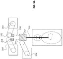
- FIG. 2A illustrates a robotic surgery system 200 .
- System 200 has first arm 202 and second arm 204 holding endoscopic tool bases 206 and 208, respectively.
- Tool base 206 has controllable endoscope sheath 210 operatively connected thereto.
- Tool base 208 has flexible endoscope leader 212 operatively connected thereto.
- Arms 202 and 204 align tool bases 206 and 208 such that proximal end 216 of sheath 210 is distal of the proximal end 222 of leader 212, and such that leader 212 remains axially aligned with sheath 210 at an approximate angle of 180 degrees between the two arms, resulting in a "virtual rail" where the rail is approximately straight, or at 180 degrees. As will be described later, the virtual rail may have angles between 90-180 degrees.
- sheath 210 is robotically inserted through, for example, a tracheal tube (not shown) in the mouth of and into patient 211, and ultimately into the patient's bronchial system, while continually maintaining the virtual rail during insertion and navigation.
- the arms may move sheath 210 and endoscope 212 axially relative to each other and in to or out of patient 211 under the control of a doctor (not shown) at a control console 203 (from FIG. 2B ).
- Navigation is achieved, for example, by advancing sheath 210 along with leader 212 into the patient 211, then leader 212 may be advanced beyond distal end 213 of the sheath, and the sheath 210 may then be brought even with the leader 212, until a desired destination is reached.
- Other modes of navigation may be used, such as and not by way of limitation using a guide wire through the working channel of the leader 212.
- the physician may be using any number of visual guidance modalities or combination thereof to aid navigation and performing the medical procedure, e.g ., fluoroscopy, video, CT, MR etc.
- Distal end 220 of leader 212 may then be navigated to an operative site and tools are deployed through a longitudinally-aligned working channel within leader 212 to perform desired procedures.
- the virtual rail may be maintained during the navigation procedure and any subsequent operative procedures. Any number of alternative procedures that may require a tool or no tool at all can be performed using the flexible endoscope sliding through the sheath, as the skilled artisan will appreciate
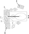
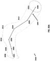
- FIG. 2B illustrates an overhead view of system 200 where anesthesia cart 201 is provided towards the head of the patient. Additionally, control console 203 with a user interface is provided to control sheath 210, endoscope leader 212, and the associated arms 202 and 204 and tool bases 206 and 208 (see FIG. 2A ).
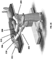
- FIG. 2C shows an angled view of system 200 in FIG. 2A .
- Tool modules 206 and 208 with associated sheath 210 and leader 212 are attached to arms 202 and 204 and arranged in a 180 degree virtual rail. The arms are shown on a single cart, which provides added compactness and mobility.
- tool bases 206 and 208 have pulley systems or other actuation systems to tension tendons in sheath 210 and leader 212 to steer their respective distal ends.
- Tool bases 206 and 208 may provide other desired utilities for the sheath and endoscope, such as pneumatic pressure, electrical, data communication (e.g., for vision), mechanical actuation (e.g., motor driven axels) and the like. These utilities may be provided to the tool bases through the arms, from a separate source or a combination of both.
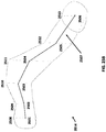
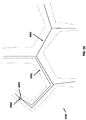
- FIGS. 2D and 2E illustrate alternative arrangements of arms 202 and 204 showing the versatility of the robotic surgical system.
- arms 202 and 204 may be extended to position the instrument (comprising sheath 210 and leader 212 ) to enter the mouth of patient 211 at 75 degrees from horizontal, while still maintaining a 180 degree virtual rail. This may be done during the procedure if required to accommodate space requirements within the room.
- the 75 degree angle was chosen for demonstrative purposes, not by way of limitation.
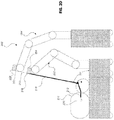
- FIG. 2E shows an alternative arrangement of arms 202 and 204 where the tool bases 206 and 208 are aligned to create a virtual rail with a 90 degree angle.
- the instrument comprising sheath 210 and leader 212 ) enters the mouth of patient 213 at 75 degrees from horizontal.
- Tool bases 206 and 208 are aligned such that the leader 212 bends 90 degrees at tool base 206 prior to entering the mouth of patient 213.
- a rigid or semi-rigid structure such as a tube, may be used to ensure smooth extension and retraction of the leader 212 within sheath 210.
- Extension and retraction of leader 212 within sheath 210 may be controlled by moving tool base 208 either closer or farther from tool base 206 along the linear path tracked by leader 212. Extension and retraction of sheath 210 may be controlled by moving tool base 206 closer or farther from patient 213 along the linear path tracked by sheath 210. To avoid unintended extension or retraction of leader 212 while extending or retracting sheath 210, tool base 208 may also be moved along a linear path parallel to sheath 210.
- Virtual rails are useful in driving both rigid instrument and flexible instruments, and especially where there are telescoping requirements.
- the use of a virtual rail is not limited to a single rail but can consist of multiple virtual rails where the arms act in concert to maintain the individual virtual rails in performance of one or more procedures.
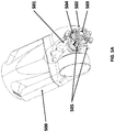
- FIG. 3A illustrates an overhead view of a system with multiple virtual rails.
- robot arms 302, 304 and 306 respectively hold tool bases 308, 310, and 312.
- Tool bases 308 and 310 may be operatively coupled to flexible tool 314 and tool 316.
- Tool 314 and tool 316 may be a telerobotically-controlled flexible endoscopic instruments.
- Tool base 312 may be operatively coupled to a dual lumen sheath 318, where each lumen receives tools 314 and 316.
- Arms 302 and 304 may each maintain a virtual rail with robotic arm 306, and movements of all three arms may be coordinated to maintain virtual rails and move tools 314, 316 and sheath 318 relative to each other and the patient.
- FIG. 3B illustrates the use of the robotic surgery system from FIG. 3A with an additional robotic arm 320 and associated tool base 322 and tool 324.
- sheath 325 may have three lumens.
- sheath 325 may comprise more than one sheath to provide access to tools 314, 316, and 324.
- the ability to increase or reduce the number of arms with associated modules and instruments permits a great number and flexibility of surgical configurations, which, in turn, permits re-purposing of expensive arms and use of multiple relatively-inexpensive modules to achieve great versatility at reduced expense.
- a plurality of arms and/or platforms may be utilized.
- Each platform / arm must be registered to the others, which can be achieved by a plurality of modalities including, vision, laser, mechanical, magnetic, or rigid attachment.
- registration may be achieved by a multi-armed device with a single base using mechanical registration.
- mechanical registration an exemplary system may register arm / platform placement, position, and orientation based on their position, orientation and placement relative to the single base.
- registration may be achieved by a system with multiple base using individual base registration and "hand-shaking" between multiple robot arms.
- registration may be achieved by touching together arms from different bases, and calculating locations, orientation and placement based on (i) the physical contact and (ii) the relative locations of those bases.
- registration targets may be used to match the position and orientations of the arms relative to each other. Through such registration, the arms and instrument driving mechanisms may be calculated in space relative to each other.
- robotic surgical system 100 may be configured in a manner to provide a plurality of surgical system configurations, such as by changing IDM 117 and tool 118 (also known as an end effector).
- the system may comprise one or more mobile robotic platforms staged at different locations in the operative room, or at a convenient nearby location. Each platform may provide some or all of power, pneumatic pressure, illumination sources, data communication cables and control electronics for a robotic arm that is coupled to the platform, and the module may draw from these utilities as well.
- System 100 may alternatively have multiple arms 102 mounted on one or more mobile carts 101, or the arms may be mounted to the floor in order to provide a plurality of surgical configurations.
- some exemplary systems are designed to readily exchange between multiple modules or end effector mechanisms.
- Various surgical procedures or steps within a procedure may require the use of different modules and the associated instrument sets, for example, exchanging between different sized sheath and endoscope combinations. Interchangeability allows the system to reconfigure for different clinical procedures or adjustments to surgical approaches.
- FIG. 4 illustrates a robotic surgery system with interchangeable IDMs and tools.
- Surgical system 400 has a mechanical arm 401 to which IDM 402 and tool 403 are attached. Attached to system cart 404, IDMs 405 and 406, and associated tools 407 and 408 may be exchanged onto robotic arm 401 or picked up by a different robotic arm (not shown) to be used alone in concert with another IDM and tool.
- Each IDM may be a dedicated electromechanical system which may be used to drive various types of instruments and tools for specified procedures.
- To drive instruments, each IDM may comprise an independent drive system, which may include a motor. They may contain sensors (e.g., RFID) or memory chips that record their calibration and application related information. A system calibration check may be required after a new mechanism is connected to the robot arm.
- an IDM may control an endoscopic sheath or flexible endoscopic leader.
- system 400 may exchange IDM 402 for IDMs 405 and 406 by itself through the use of global registration and sensors.
- IDMs 406 and 408 are stored on system cart 404 at predetermined "docking stations" which are configured with identification and proximity sensors. Sensors at these stations may make use of technologies such as RFID, optical scanners ( e.g ., bar codes), EEPROMs, and physical proximity sensors to register and identify which IDMs are "docked” at the docking station.
- the identification and proximity sensors allow the IDMs that are resting in the docking stations to be registered relative to the robotic arm(s).
- multiple arms may access the IDMs on the docking station using the combination of registration system and sensors discussed above.
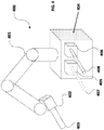
- FIG. 5 illustrates a mechanism changer interface in a robotic system.
- FIG. 5A specifically illustrates an implementation of a mechanism changer interface coupled to a robotic arm in a robotic system, in accordance with an embodiment of the present invention.
- the distal portion of robotic arm 500 comprises an articulating joint 501 coupled to a "male" mechanism changer interface 502.
- Articulating joint 501 provides an additional degree of freedom with respect to manipulating an instrument device mechanism (not shown) that is configured to couple to robotic arm 500.
- Male mechanism changer interface 502 provides a male connector interface 503 that provides a strong, physical connection to the reciprocal female receptacle connector interface on the IDM (not shown).
- the spherical indentations on the male connector interface 503 physically couple to reciprocal indentations on the female receptacle interface on the IDM.
- the spherical indentations may be extended when pneumatic pressure is conveyed along robotic arm 500 into male mechanism changer interface 502.
- the male mechanism changer interface 502 also provides connections 504 for transferring for pneumatic pressure to the IDM. Additionally, this example of the mechanism changer interface provides for alignment sensors 505 that ensure that the male mechanism changer interface 502 and its reciprocal female interface are properly aligned.
- FIG. 5B illustrates an alternative view of male mechanism changer interface 502 separated from robotic arm 500.
- male mechanism changer interface 502 provides for a flange-like male connector interface 503, pneumatic connectors 504, and alignment sensors 505. Additionally, an electrical interface 506 for connecting electrical signals to the reciprocal interface on the IDM (not shown).
- FIG. 5C illustrates a reciprocal female mechanism changer interface coupled to an instrument device manipulator for connecting with male mechanism changer interface 502 from FIGS. 5A and 5B .
- instrument device manipulator 507 is coupled to a female mechanism changer interface 508 that is configured to connect to male mechanism changer interface 502 on robotic arm 500.
- Female mechanism changer interface 508 provides for female receptacle interface 509 that is designed to couple to the flange-like male connector interface 503 of male mechanism changer interface 502.
- the female receptacle interface 509 also provides a groove to grip the spherical indentations on the male connector interface 503.
- Reciprocal female mechanism changer interface 508 also provides with pneumatic connectors 510 to accept the pneumatic pressure conveyed from connectors 504.
- FIG. 5D illustrates an alternative view of female mechanism changer interface 508 from FIG. 5C .
- reciprocal mechanism changer interface 508 contains a receptacle interface 509, pneumatic connectors 510 for interfacing with mechanism changer interface 502 on robotic arm 500.
- mechanism changer interface 508 also provides for an electrical module 511 for transmitting electrical signals - power, controls, sensors - to module 506 in mechanism changer interface 502.
- FIGS. 6 , 7 , 8A , and 8B illustrate interchangeable modules that may be operated using system 400 from FIG. 4 .
- FIG. 6 illustrates an exemplary system that uses a single port laparoscopic instrument 601 connected through an instrument interface 602 on a single robotic arm 603 that is directed at the abdomen 604 of a patient 605.
- FIG. 7 illustrates an exemplary system with two sets of robotic subsystems 701 and 704, each with a pair of arms 702, 703 and 705, 706 respectively. Connected through instrument interfaces at the distal end of arms 702, 703, 705, 706 are laparoscopic instruments 707, 708, 709, 710 respectively, all instruments working together to perform procedures in an individual patient 711.
- FIG. 8A illustrates an exemplary system with a subsystem 801 with a single robotic arm 802, where a microscope tool 804 connected to the robotic arm 802 through an instrument interface 803.
- the microscopic tool 804 may be used in conjunction with a second microscope tool 805 used by a physician 806 to aid in visualizing the operational area of a patient 807.
- FIG. 8B illustrates an exemplary system where subsystem 801 from FIG. 8A may be used in conjunction with subsystem 808 to perform microsurgery.
- Subsystem 808 provides arms 809 and 810, each with microsurgical tools 811 and 812 connected through instrument interfaces on each respective arm.
- the one or more arms may pick up and exchange tools at a table or other suitable holding mechanism within reach of the robotic arm, such as a docking station.
- the mechanism changer interface may be a simple screw to secure an associated IDM. In other exemplary systems, the mechanism changer interface may be a bolt plate with an electrical connector.
- FIG. 9A illustrates a portion of a robotic medical system that includes a manipulator.
- System 900 includes a partial view of a robotic arm 901, an articulating interface 902, an instrument device manipulator ("IDM”) 903, and an endoscopic tool 904.
- the robotic arm 901 may be only a linkage in a larger robotic arm with multiple joints and linkages.
- the articulating interface 902 couples IDM 903 to robotic arm 901.
- the articulating interface 902 may also transfer pneumatic pressure, power signals, control signals, and feedback signals to and from the arm 901 and the IDM 903.
- the IDM 903 drives and controls the endoscopic tool 904.
- the IDM 903 uses angular motion transmitted via output shafts in order to control the endoscopic tool 904.
- the IDM 903 may comprise a gear head, motor, rotary encoder, power circuits, control circuits.
- Endoscopic tool 904 may comprise a shaft 909 with a distal tip and proximal end.
- a tool base 910 for receiving the control signals and drive from IDM 903 may be coupled to the proximal end of the shaft 909. Through the signals received by the tool base 910, the shaft 909 of endoscopic tool 904 may be controlled, manipulated, and directed based on the angular motion transmitted via output shafts 905, 906, 907, and 908 (see FIG. 9B ) to the tool base 910 of the endoscopic tool 904.
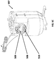
- FIG. 9B illustrates an alternative view of the robotic medical system disclosed in FIG. 9A .
- the endoscopic tool 904 has been removed from the IDM 903, to reveal the output shafts 905, 906, 907, and 908. Additionally, removal of the outer skin / shell of IDM 903 reveals the components below the IDM top cover 911.
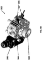
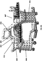
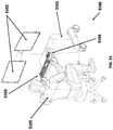
- FIG. 10 illustrates an alternative view of the independent drive mechanism from FIGS. 9A , 9B with a tension sensing apparatus.
- parallel drive units 1001, 1002, 1003, and 1004 are the structurally largest components in the IDM 903.
- a drive unit 1001 may be comprised of a rotary encoder 1006, a motor 1005, and a gear head 1007.
- Drive units 1002, 1003, and 1004 may be constructed similarly - comprising of motors, encoders, and gear heads underneath the top cover 911.
- the motor used in the drive unit is a brushless motor.
- the motor may be a direct current servo motor.
- Rotary encoder 1006 monitors and measures the angular speed of the driveshaft of motor 1005.
- rotary encoder 1006 may be a redundant rotary encoder.
- the torque generated by the motor 1005 may be transmitted to gear head 1007 through a shaft coupled to the rotor of motor 1005.
- the gear head 1007 may be attached to the motor 1005 in order to increase torque of the motor output, at the cost of the rotational speed.
- the increased torque generated by gear head 1007 may be transmitted into gear head shaft 1008.
- drive units 1002, 1003, and 1004 transmit their respective torque out through gear head shafts 906, 907, and 908.
- Each individual drive unit may be coupled to a motor mount at its distal end and a strain gauge mount towards its proximal end.
- the distal end of drive unit 1001 may be clamped to motor mount 1009 and strain gauge mount 1010.
- drive unit 1002 may be clamped to motor mount 1011, while also both being clamped to strain gauge mount 1010.
- the motor mounts are constructed from aluminum to reduce weight.
- the strain gauge mounts may be adhered to a side of the drive unit.
- the strain gauge mounts may be constructed from aluminum to reduce weight.
- Electrical strain gauges 1012 and 1013 are potted and soldered to the strain gauge mount 1010 and attached using screws to motor mounts 1009 and 1011 respectively.
- a pair of strain gauges (not shown) proximal to drive units 1003 and 1004 are potted and soldered to strain gauge mount 1014 and attached to motor mounts 1015 and 1016 respectively using screws.
- the electrical strain gauges may be held in place to their respective motor mount using side screws.
- side screws 1019 may be inserted into motor mount 1009 to hold in place strain gauge 1012.
- the gauge wiring in the electrical strain gauges may be vertically arranged in order to detect any vertical strain or flex in the drive unit which may be measured as horizontal displacement by the motor mount (1009, 1011) relative to the strain gauge mount (1010).
- strain gauge wiring may be routed to circuits on the strain gauge mounts.
- strain gauge 1012 may be routed to circuit board 1017 which may be mounted on strain gauge mount 1010.
- strain gauge 1013 may be routed to circuit board 1018 which may be also mounted on strain gauge mount 1010.
- circuit boards 1017 and 1018 may process or amplify the signals from strain gauges 1012 and 1013 respectively. The close proximity of circuit boards 1017 and 1018 to strain gauges 1012 and 1013 helps to reduce the signal to noise ratio in order to obtain more accurate readings.
- FIG. 11A illustrates a cutaway view of the independent drive mechanism from FIGS. 9A , 9B , and 10 from an alternate angle.
- the drive unit 1001 comprises of motor 1005, rotary encoder 1006, and gear head 1007.
- the drive unit 1001 may be coupled to the motor mount 1009 and passes through the top cover 911 through which the output shaft 905 may be driven at the desired angular speed and torque.
- the motor mount 1009 may be coupled to a vertically aligned strain gauge 1012 using side screws.
- the stain gauge 1012 may be potted into the strain gauge mount 1010.
- the output shaft 905 includes a labyrinth seal over a gear head shaft.
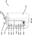
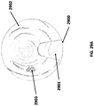
- FIG. 11B illustrates a cutaway view of the previously discussed independent drive mechanism in combination with an endoscopic tool.
- endoscopic tool 904 mounted on IDM 903 contains pulleys that are longitudinally aligned with the output shafts of the IDM 903, such as pulley 1102 which may be concentric with output shaft 905.
- Pulley 1102 may be housed inside of a precision cut chamber 1103 within tool base 910 such that the pulley 1102 may be not rigidly fixed inside chamber 1103 but rather “floats" within the space in the chamber 1103.
- the splines of the pulley 1102 are designed such that they align and lock with splines on output shaft 905.
- the splines are designed such that there may be only a single orientation for the endoscopic tool to be aligned with IDM 903. While the splines ensure pulley 1102 is concentrically aligned with output shaft 905, pulley 1102 may also incorporate use of a magnet 1104 to position and axially hold the floating pulley 1102 in alignment with output shaft 905. Locked into alignment, rotation of the output shaft 905 and pulley 1102 tensions the pull wires within endoscopic tool 904, resulting in articulation of shaft 909.
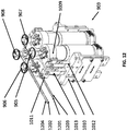
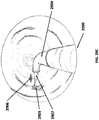
- FIG. 12 illustrates an alternative view of the previously-discussed independent drive mechanism with pull wires from an endoscopic tool.
- the endoscopic tool may use pull wires in order to articulate and control the shaft.
- these pull wires 1201, 1202, 1203, and 1204 may be tensioned or loosened by the output shafts 905, 906, 907, and 908 respectively of the IDM 903. Accordingly, the pull wires may be robotically controlled via the control circuity in IDM 903.
- the pull wires 1201, 1202, 1203, and 1204 transfer force back to the output shafts and thus to the motor mounts and drive units.
- tension in the pull wires directed away from the output shaft results in forces pulling the motor mounts 1009 and 1011.
- This force may be measured by the strain gauges, such as 1012 and 1013, since the strain gauges are both coupled to motor mounts 1009 and 1011 and potted in the strain gauge mount 1010.
- FIG. 13 illustrates a conceptual diagram that shows how horizontal forces may be measured by a strain gauge oriented perpendicular to the forces.
- a force 1301 may directed away from the output shaft 1302.
- the force 1301 results in horizontal displacement of the motor mount 1303.
- the strain gauge 1304, coupled to both the motor mount 1303 and ground 1305, may thus experience strain as the motor mount 1303 causes the strain gauge 1304 to flex (causing strain) in the direction of the force 1301.
- the amount of strain may be measured as a ratio of the horizontal displacement of the tip of strain gauge 1304 to the overall horizontal width of the strain gauge 1304. Accordingly, the strain gauge 1304 may ultimately measure the force 1301 exerted on the output shaft 1302.
- the assembly may incorporate a device to measure the orientation of instrument device manipulator 903, such as an inclinometer or accelerometer.
- a device to measure the orientation of instrument device manipulator 903 such as an inclinometer or accelerometer.
- measurements from the device may be used to calibrate readings from the strain gauges, since strain gauges may be sensitive to gravitational load effects resulting from their orientation relative to ground.
- the weight of the drive unit may create strain on the motor mount which may be transmitted to the strain gauge, even though the strain may not result from strain on the output shafts.
- the output signals from the strain gauge circuit boards may be coupled to another circuit board for processing control signals.
- power signals are routed to the drive units on another circuit board from that of processing control signals.
- the motors in drive units 1001, 1002, 1003, and 1004 ultimately drive output shafts, such as output shafts 905, 906, 907, and 908.
- the output shafts may be augmented using a sterile barrier to prevent fluid ingress into the instrument device manipulator 903.
- the barrier may make use of a labyrinth seal ( 1105 from FIG. 11A ) around the output shafts to prevent fluid ingress.
- the distal end of the gear head shafts may be covered with output shafts in order to transmit torque to a tool.
- the output shafts may be clad in a steel cap to reduce magnetic conductance.
- the output shafts may be clamped to the gear head shafts to assist transfer of torque.
- Instrument device mechanism 903 may also be covered in a shell or skin, such as outer shell / skin 1101.
- the shell provides fluid ingress protection during operation, such as during medical procedures.
- the shell may be constructed using cast urethane for electromagnetic shielding, electromagnetic compatibility, and electrostatic discharge protection.
- Each of those output shafts in individually tension may pull wires in an endoscopic tool that makes use of steerable catheter technology.
- Tensile force in the pull wires may be transmitted to the output shafts 905, 906, 907 and 908 and down to a motor mount, such as motor mounts 1009 and 1011.
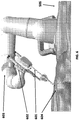
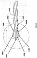
- FIG. 14 is an illustration of an endoscopic tool that may be used in conjunction with a robotic system 100 from FIG. 1 .
- Endoscopic tool 1400 may be arranged around nested longitudinally-aligned tubular bodies, referred to as a "sheath" and a "leader".
- the sheath 1401, the tubular tool with the larger outer diameter may be comprised of a proximal sheath section 1402, a distal sheath section 1403, and a central sheath lumen (not shown).
- the distal sheath portion 1403 may be articulated in the operator's desired direction.
- leader 1405 Nested within the sheath 1401 may be a leader 1405 with a smaller outer diameter.
- the leader 1405 may comprise a proximal leader section 1406 and a distal leader section 1407, and a central working channel.
- leader base 1408 controls articulation of the distal leader section 1407 based on control signals communicated to leader base 1408, often from the IDMs ( e.g., 903 from FIG. 9A ).
- Both the sheath base 1404 and leader base 1408 may have similar drive mechanisms, to which control tendons within sheath 1401 and leader 1405 are anchored. For example, manipulation of the sheath base 1404 may place tensile loads on tendons in the sheath 1401, therein causing deflection of distal sheath section 1403 in a controlled manner. Similarly, manipulation of the leader base 1408 may place tensile loads on the tendons in leader 1405 to cause deflection of distal leader section 1407. Both the sheath base 1404 and leader base 1408 may also contains couplings for the routing of pneumatic pressure, electrical power, electrical signals or optical signals from the IDMs to the sheath 1401 and leader 1404.
- Control tendons within the sheath 1401 and leader 1405 may be routed through the articulation section to an anchor positioned distal to the articulation section.
- the tendons within sheath 1401 and leader 1405 may consist of a stainless steel control tendon routed through a stainless steel coil, such as a coil pipe.
- a stainless steel coil such as a coil pipe.
- Other materials may be used for the tendons, such as Kevlar, Tungsten and Carbon Fiber. Placing loads on these tendons causes the distal sections of sheath 1401 and leader 1405 to deflect in a controllable manner.
- the inclusion of coil pipes along the length of the tendons within the sheath 1401 and leader 1405 may transfer the axial compression back to the origin of the load.
- the endoscopic tool 1400 has the ability to navigate lumens within the human body with ease by providing a plurality of degrees of freedom (each corresponding to an individual tendon) control at two points - distal sheath section 1403 and distal leader section 1407 - along its length.
- a plurality of degrees of freedom each corresponding to an individual tendon
- up to four tendons may be used in either the sheath 1401 and/or leader 1405, providing up to eight degrees of freedom combined.
- up to three tendons may be used, providing up to six degrees of freedom.
- the sheath 1401 and leader 1405 may be rolled 360 degrees, providing for even more tool flexibility.
- the combination of roll angles, multiple degrees of articulation, and multiple articulation points provides the surgeon with a significant improvement to the instinctive control of the device as it navigates a tortuous path within the human body.
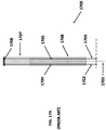
- FIGS. 15A , 15B , 15C , 16A , and 16B generally illustrate aspects of a robotically-driven endoscopic tool, such a sheath 210 and leader 212 from FIG. 2 , in accordance with an embodiment of the present invention.
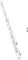
- FIG. 15A illustrates an endoscopic tool with sheath 1500 having distal end 1501 and proximal end 1502 and lumen 1503 running between the two ends. Lumen 1503 may be sized to slidingly receive a flexible endoscope (such as leader 1600 from FIG. 16 ).
- Sheath 1500 has walls 1504 with tendons 1505 and 1506 running inside the length of walls 1504 of sheath 1500.
- Tendons 1505 and 1506 may slidingly pass through conduits 1507 and 1508 in walls 1504 and terminate at distal end 1501.
- the tendons may be formed from steel. Appropriate tensioning of tendon 1505 may compress distal end 1501 towards conduit 1507, while minimizing bending of the helixed section 1510. Similarly, appropriate tensioning of tendon 1506 may compress distal end 1501 towards conduit 1508.
- lumen 1503 may not be concentric with sheath 1500.
- Tendons 1505 and 1506 and associated conduits 1507 and 1508 from sheath 1500 from FIG. 15A preferably do not run straight down the entire length of sheath 1500, but helix around sheath 1500 along helixed section 1510 and then run longitudinally straight (i .e., approximately parallel to the neutral axis) along distal section 1509. It will be appreciated that helixed section 1510 may begin from the proximal end of distal section 1509 extending proximally down sheath 1510 and may terminate at any desired length for any desired or variable pitch.
- the length and pitch of helixed section 1510 may be determined based on the desired properties of sheath 1500, taking into account desired flexibility of the shaft, and increased friction in the helixed section 1510.
- Tendons 1505 and 1506 may run approximately parallel to central axis 1511 of sheath 1500 when not in the helixed section, such as the proximal and distal sections of the endoscope 1500.
- the tendon conduits may be at ninety degrees to each other (e.g., 3-, 6-, 9- and 12-o'clock).
- the tendons may be spaced one hundred and twenty degrees from each other, e.g., three total tendons.
- the tendons may be not be equally spaced. In some embodiments, they may be to one side of the central lumen. In some embodiments, the tendon count may differ from three or four.
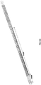
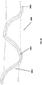
- FIG. 15B shows a three-dimensional illustration of an embodiment of sheath 1500 with only one tendon for the purpose of clarifying the distinction between non-helixed section 1509 and a variable pitch helixed section 1510. While one tendon may be used, it may be preferable to use multiple tendons.
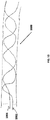
- FIG. 15C shows a three-dimensional illustration of an embodiment of sheath 1500 with four tendons extending along distal section 1509, variable pitch helixed section 1510.
- FIG. 16A illustrates an endoscopic leader 1600 with distal end 1601 and proximal end 1602, that may be sized to slidingly reside within the sheath 1500 from FIG. 15 .
- Leader 1600 may include at least one working channel 1603 passing through it.
- Proximal end 1502 of sheath 1500 and proximal end 1602 of leader 1600 are, respectively, operatively connected to tool bases 206 and 208 from FIG. 2 respectively.
- Tendons 1604 and 1605 slidingly pass through conduits 1606 and 1607 respectively in walls 1608 and terminate at distal end 1601.
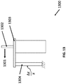
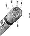
- FIG. 16B illustrates the distal end 1601 of leader 1600, an exemplary embodiment, that has imaging 1609 (e.g., CCD or CMOS camera, terminal end of imaging fiber bundle etc.), light sources 1610 (e.g., LED, optic fiber etc.) and may include at least one working channel opening 1603.
- imaging 1609 e.g., CCD or CMOS camera, terminal end of imaging fiber bundle etc.
- light sources 1610 e.g., LED, optic fiber etc.
- Other channels or operating electronics 1606 may be provided along leader 1600 to provide various known capabilities at the distal end, such as wiring to camera, insufflation, suction, electricity, fiber optics, ultrasound transducer, EM sensing, and OCT sensing.
- the distal end 1601 of leader 1600 may include a "pocket" for insertion of a tool, such as those disclosed above.
- the pocket may include an interface for control over the tool.
- a cable such as an electrical or optical cable, may be present in order communicate with the interface.
- both sheath 1500 from FIG. 15A and leader 1600 from FIG. 16A may have robotically-controlled steerable distal ends.
- the structure of sheath 1500 and leader 1600 enabling this control may be substantially the same.
- discussion for the construction of sheath 1500 will be limited to that of the sheath 1500 with the understanding that the same principles apply to the structure of the leader 1600.
- tendons 1604 and 1605 and associated conduits 1606 and 1607 from the leader 1600 from FIG. 16A do not run longitudinally straight ( i.e., approximately parallel to the neutral axis) down the length of leader 1600, but helix along different portions of leader 1600.
- the helixed sections of leader 1600 may be determined based on the desired properties of the leader, taking into account desired flexibility of the shaft, and increased friction in the helixed section.
- Tendons 1604 and 1605 run approximately parallel to central axis of leader 1600 when not in the helixed section.
- the helixed section may help isolate the bending to the distal section, while minimizing any bending that occurs along the shaft proximal to the distal section.
- the helix pitch of the conduits in sheath 1500 and leader 1600 may be varied along the length of the helixed section, which, as more fully described below will alter the stiffness/rigidity of the shaft.
- sheath 1500 and leader 1600 present significant advantages over previous flexible instruments without helixed conduits, particularly when navigating non-linear pathways in anatomical structures.
- sheath 1500 and leader 1600 may be preferable for sheath 1500 and leader 1600 to remain flexible over most of the lengths thereof, and to have a controllably steerable distal end section, while also minimal secondary bending of the instrument proximal to the distal bending section.
- tensioning the tendons in order to articulate the distal end resulted in unwanted bending and torqueing along the entire length of the flexible instrument, which may be referred to as “muscling” and “curve alignment” respectively.
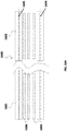
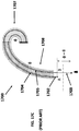
- FIGS. 17A to 17D illustrates how prior art flexible instruments exhibit undesirable "muscling" phenomenon when tendons are pulled.
- a previous endoscope 1700 may have four tendons or control wires along the length of the endoscope 1700 that run approximately parallel to the neutral axis 1701. Only tendons 1702 and 1703 are shown in cross section traveling through conduits 1704 and 1705 (also known as control lumens) in the shaft wall, each of which are fixedly connected to a control ring 1706 on the distal end of the endoscope 1700.
- Endoscope 1700 may be intentionally designed to have a bending section 1707 and shaft 1708.
- the shaft 1708 may incorporate stiffer materials, such as stiffeners.
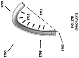
- FIG. 17B illustrates an idealized articulation of bending section 1707.
- articulation of only the distal bending section 1707 results in an amount represented by ⁇ , where the length difference at the proximal ends of tendons 1702 and 1703 would be a f( ⁇ ).
- the shaft 1708 would remain straight along the neutral axis 1701. This may be achieved by having a proximal region 1708 of a significantly higher stiffness than the distal region of 1707.
- FIG. 17C illustrates the real world result from tensioning tendon 1703.
- pulling tendon 1703 results in compressive forces along the entire length of the shaft as the tension is non-localized.
- the entire compressive load would transmit equally down the central axis and most or all bending would occur at the bending section 1707.
- the axial load is transferred off the neutral axis 1701 in the same radial orientation of the neutral axis which creates a cumulative moment along the neutral axis.
- FIG. 17D illustrates the forces that contribute to muscling in three-dimensions.
- tensioning tendon 1703 along endoscope 1700 causes the tendon 1703 to directionally exert forces 1712 towards one side of the instrument.
- the direction of forces 1712 reflect that the tension in tendon 1703 causes the tendon to seek to follow a straight line from the tip of the distal bending section 1707 to the base of the shaft 1708, i.e., the lowest energy state as represented by the dotted line 1713.
- the shaft 1708 is rigid ( i.e., not susceptible to bending under the applicable forces)
- only the distal bending section 1707 will bend.
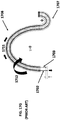
- FIGS. 17E to 17H illustrate how previous flexible instruments suffer from curve alignment phenomenon during use in non-linear pathways.
- FIG. 17E shows a previous flexible endoscope 1700 at rest within a non-linear path, represented by having a bend ⁇ along the shaft 1708 of endoscope 1700. For example, this may result from the instrument navigating past a bend in the bronchial lumens. Due to the non-linear bend, tendons 1702 and 1703 in endoscope 1700 need to lengthen or shorten at the proximal end by a length to accommodate the non-linear bend, which length is represented by F( ⁇ ).
- Extension and compressive forces exist on the lumens/conduits at the top and bottom of the bend, as depicted by arrows 1709 (extension forces) and 1710 (compressive forces) respectively. These forces exist because the distance along the top of the bend is longer than the neutral axis, and the distance along the inside of the bend is shorter than the neutral axis.
- FIG. 17F illustrates the mechanics of articulating the distal bending section 1707 of the endoscope 1700 in the same direction as bend ⁇ , where one would pull tendon 1703. This results in compressive forces along the length of the flexible instrument (as previously described), and tendon 1703 also exerts downward forces against the non-linear conduit through which it passes, which applies an additive compression in the shaft 1708 previously compressed by the anatomical tortuosity. Since these compressive leads are additive, the shaft 1708 will further bend in the same direction as the distal bending section 1707.
- the additional compressive force along the non-linear conduit may be undesirable because: (i) it may unintentionally force the flexible instrument against the anatomy; (ii) potential for injury distracts the operator because he/she has to constantly monitor what the shaft is doing, when he/she should be able to "assume” the anatomy is governing the profile of the instrument shaft; (iii) it is an inefficient way to bend the instrument, (iv) it is desired to isolate bending at the distal section to aid in predictability and controllability (i.e., ideal instrument will have bending section that bends as commanded and is not a function of the anatomical non-linear path), and (v) it forces a user to pull on a tendon 1103 an unpredictable additional length ( ⁇ + ⁇ + ⁇ ).
- FIG. 17G illustrates a scenario where one desires to articulate the distal end opposite to bend ⁇ , requiring pulling tendon 1702.
- Pulling tendon 1702 applies a compressive load 1711 along the top of the curve, which is in contrast to the extension loads for the bend in its resting state as shown in FIG. 17E .
- Tendons 1702 will attempt to return to its lowest energy state, i.e., where the compressive load 1711 rests on the inside of the bend ⁇ , and cause the shaft 1708 to rotate in the direction of the arrow 1712 so that the tendon 1702 rests on the inside of the bend ⁇ .
- FIG. 17G illustrates a scenario where one desires to articulate the distal end opposite to bend ⁇ , requiring pulling tendon 1702.
- Pulling tendon 1702 applies a compressive load 1711 along the top of the curve, which is in contrast to the extension loads for the bend in its resting state as shown in FIG. 17E .
- Tendons 1702 will attempt to return to its lowest energy state,
- FIGS. 17I and 17J illustrate how the muscling and curve alignment phenomena is substantially resolved through the provision of a helixed section in an embodiment of the present invention, such as 1510 in FIG. 15 .
- helixing the control lumens around endoscope 1700 such as in helixed section 1510 from FIG. 15 , radially distributes compressive loads 1714 from a single tendon 1715 around endoscope 1700.
- a tensioned tendon 1715 symmetrically transmits the compressive load 1714 in multiple directions around the neutral axis
- the bending moments imposed on the shaft are also symmetrically distributed around the longitudinal axis of the shaft, which counterbalance and offset opposing compressive and tensile forces.
- the distribution of the bending moments results in minimal net bending and rotational forces, creating a lowest energy state that is longitudinally parallel to the neutral axis, as represented by the dotted line 1816. This eliminates or substantially reduces the muscling and curve alignment phenomena.
- the pitch of helixing can be varied to affect friction and the stiffness of the helixed section.
- the helixed section 1510 may be shorter to allow for a larger non-helixed section 1509, resulting in a larger articulating section and possibly less friction.
- Helical control lumens create several trade-offs. Helical control lumens still do not prevent buckling from tension in the tendons. Additionally, while muscling is greatly reduced, "spiraling"-the curving of the shaft into a spiral, spring-like pattern due to tension in the tendons-is very common. Moreover, helical control lumens requires compensation for additional frictional forces as the tendon travels through the lumen for longer distances.
- FIG. 18 illustrates the structure of a flexible endoscopic tool with an axially stiff tube within a lumen.
- a section of an endoscopic tool has a single lumen 1801 with a pull wire 1802 wrapped in a helical pattern around the shaft 1800.
- an axially stiff tube 1803 "floats" around the pull wire 1802 and within the lumen 1801.
- the floating tube 1803 anchored at the beginning and end of the helical portion of the shaft 1800, the floating tube 1803 extends and compresses in response to tension in pull wire 1802 and external tortuosity, relieving the walls of lumen 1801 from the extension and compression forces.
- the tube 1803 may be anchored by control rings at the beginning and end of the lumen.
- tube 1803 may be anchored using solder, welding, gluing, bonding, or fusing methods to the beginning and end of the lumen.
- geometric engagement such as flared geometries, may be used to anchor tube 1803.
- the tube 1803 may be formed from hypodermic tubes, coil pipes, Bowden cables, torque tubes, stainless steel tubes, or nitinol tubes.
- the exemplary tool in FIG. 18 may be constructed by fixedly attaching the tubes to a distal end piece and proximal end piece and collectively twisting the tubes by rotating either or both end pieces.
- the rotation of the end piece(s) ensures that the tubes are helixed in the same pitch, manner, and orientation.
- the end pieces may be fixedly attached to the lumen to prevent further rotation and restrict changes to the pitch of the helixing.
- FIG. 19 illustrates the structure of a helical pattern within a lumen of a flexible endoscopic tool.
- lumen 1900 contains structures 1901 and 1902 that form a helical or spiraled pattern along its walls.
- the structures are formed from materials that are axially stiff and tube-like in shape.
- the structures may be formed from hypodermic tubes ("hypo tube"), coil pipes, or torque tubes.
- the structures may have different starting points along the walls of lumen 1900.
- the materials, composition, and characteristics of structures 1901 and 1902 may also be selected and configured for desired stiffness and length.
- the pitch of the helical pattern formed by structures 1901 and 1902 may also be configured for a desired stiffness and flexibility of lumen 1900.
- lumen 1900 may be the main central lumen of a flexible endoscope, such as leader 1600 from FIG. 16 .
- FIG. 20A illustrates an endoscopic tool from a robotic endolumenal system.
- Endoscopic tool 2000 may comprise of a flexible shaft section 2001 proximal to a support base (not shown) and a flexible articulating section 2002 coupled to a distal tip 2003. Similar to the leader 2005, endoscopic tool 2000 may be articulated by placing tensile loads on tendons within the shaft.
- FIG. 20B illustrates an alternative view of endoscopic tool 2000 from FIG. 20A .
- the distal tip 2003 may comprise a working channel 2004, four light emitting diodes 2005, and a digital camera 2006.
- the digital camera 2006 may be used, for example, to capture real-time video to assist with navigation within anatomical lumens.
- the distal tip 2003 may comprise an integrated camera assembly which houses a digital imaging means and illumination means.
- the working channel 2004 may be used for the passage of intraoperative instruments, such as bending flexures for precise articulation at an operative site.
- working channels may be incorporated to provide additional capabilities such as flush, aspiration, illumination or laser energy.
- the working channel may also facilitate the routing of control tendon assemblies and other lumens needed for the aforementioned additional capabilities.
- the working channel of the endoscopic tool may also be configured to deliver a variety of other therapeutic substances. Such substances may be cryogenic for ablation, radiation, or stem cells. These substances may be precisely delivered precisely to a target site using the insertion, articulation, and capability of the endoscopic tool of the present invention.
- the working channel may be as small at 1.2 millimeters in diameter.
- an electromagnetic (EM) tracker may be incorporated into the distal tip 2003 in order to assist with localization.
- EM electromagnetic
- a static EM field generator may be used to determine the location of the EM tracker, and thus distal tip 2003 in real-time.
- Images from camera 2006 may be ideal for navigating through anatomical spaces. Thus, obscuring of the camera 2006 from internal bodily fluids, such as mucus, may cause problems when navigating. Accordingly, the distal end 2003 of endoscopic tool 2000 may also include means for cleaning the camera 2006, such as means for irrigation and aspiration of the camera lens.
- the working channel may contain a balloon that may be inflated with fluid around the camera lens and aspirated once the lens was clear.
- the endoscopic tool 2000 enables the delivery and manipulation of small instruments within the endolumenal space.
- the distal tip may be miniaturized in order to perform endolumenal procedures, maintaining an outer diameter of no more than three millimeters ( i.e ., nine French).
- FIG. 21 illustrates the distal end of an endoscopic tool.
- endoscopic tool 2100 includes a distal end 2101 with an outer casing 2102.
- Casing 2102 may be constructed from a number of materials including stainless steel and polyether ether ketone (PEEK).
- the distal end 2101 may be packed with a working channel 2103 for slidingly providing tool access and control.
- the distal end 2101 may also provide for an array of light emitting diodes 2104 for illumination with use of the camera 2105.
- the camera may be part of a larger sensor assembly that includes one or more computer processors, a printed circuit board, and memory.
- the sensor assembly may also include other electronic sensors such as gyroscopes and accelerometers (usage discussed later).
- steerable catheters are traditionally manufactured by braiding wires or fibers, i.e ., braid wire, around a process mandrel with pull lumens in a braiding machine, i.e., braider, and a polymer jacket applied over the braid wires.
- braiding machine i.e., braider
- sheath and leader endoscopic tools may be constructed using aspects of steerable catheter construction methodologies.
- FIG. 22 illustrates a flowchart for an exemplary method of constructing an endoscopic device with helixed lumens.
- a main process mandrel may be selected to create a cavity in the endoscope for a central lumen that may be used a working channel.
- Supplemental mandrels may be selected to create cavities in the wall of the endoscope for use as control (pull) lumens.
- the main process mandrel may exhibit larger outer diameters (OD) than the supplemental mandrels to reflect the relative size differential between a working channel and pull lumens.
- the supplemental mandrels may be constructed a metal or thermoset polymer that may or may not be coated with a lubricious coating, such as PTFE.
- the main process mandrel may be inserted into a feed tube of a braider that rotates relative to a fixed braid cone support tube and braid cone holder.
- the supplemental mandrels may also be inserted into the feed tube in parallel fashion to the main process mandrel.
- smaller supplemental mandrels are passed through the center of the horn gears for braiding.
- the main process mandrel may be advanced through the feed tube. As the main process mandrel progresses, it eventually emerges through a center hole in a nose cone. Similarly, the supplemental mandrels are advanced through to also emerge through outer holes in the nose cone. This contrasts with traditional endoscope construction, where supplemental mandrels are typically advanced through separate feed tubes to emerge from the center of the horn gears.
- the main process mandrel and supplemental mandrels are braided together using braid wire as they emerge through the nose cone.
- the nose cone provides a round, smooth shape on which the braid wire from the surrounding horn gears may easily slide around the main process mandrel during the braiding process.
- the nose cone rotates, ensuring that the supplemental mandrels in the outer holes are braided in a spiraled fashion around the main process mandrel.
- the horn gears translate and rotate to lay braid wire around both the main process mandrel and supplemental mandrels at a pre-determined pattern and density.
- This exemplary method of braiding is significantly different from traditional methods of endoscope construction, where the nose cone is typically held in a position that is radially fixed relative to the braid cone holder using a set screw keyed to the braid cone holder.
- specialized hardware is required for the braiding process in order to manufacture catheter-like endoscopes with helical control lumens.
- FIG. 23 illustrates a specialized system for manufacturing an endoscope with helical pull lumens.
- the nose cone 2301 may be fixedly coupled to a rotating feed tube 2302 using a set screw that holds the nose cone 2301 in a fixed position relative to the feed tube 2302.
- nose cone 2301 rotates as the feed tube 2302 rotates.
- traditional systems typically use a set screw to fixedly couple the nose cone 2301 to the braid cone support holder 2305, which does not rotate.
- the center hole 2303 of the nose cone 2301 may be aligned with the rotating feed tube 2302 in order to smoothly pull the main process mandrel 2304 through both structures.
- the rotating feed tube 2302 has an outside diameter less than the interior diameter of the braid cone support tube 2306, also known as a mandrel guide tube, and an interior diameter larger than the circumferential space of the center hole 2303 of the nose cone 2301.
- the rotating feed tube 2302 may generally be large enough for the main process mandrel 2304 and the supplemental mandrels to be passed through to the nose cone 2301 without entanglement.
- the rotating feed tube 2302 may be long enough to pass through the center of the horn gears of the braider.
- the rotating feed tube 2302 may be attached to a mechanism that may hold bobbins of material for the supplemental mandrels that will be passed through the feed tube 2302 to supplemental holes around the nose cone 2301.
- the feed tube 2302 may be attached to a drive mechanism that controls the rate of rotation of the feed tube 2302 and thus the rotation of the nose cone 2301.
- the drive mechanism may be a rotating gear 2307.
- the drive mechanism is either geared to the braider itself or independently controlled to vary or hold constant the rate of rotation of the rotating feed tube 2302 and thus the rate of rotation of the nose cone 2301.
- the rate of rotation and the rate of braiding will govern the pitch of the supplemental mandrels on the main process mandrel 2304. As discussed earlier, this may affect the flexibility, stiffness, and "pushability" of the device.
- FIG. 24 illustrates a specialized nose cone for manufacturing helical lumens in an endoscopic device.
- Rotating the nose cone 2400 at the same time that the main process mandrel 2401 is pulled through the nose cone 2400 allows for supplemental mandrels 2402, 2403, and 2404 to be applied in a helical pattern around the mandrel 2401 through supplemental holes 2405, 2406, and 2407 respectively that surround the center hole 2408, similar to how the horn gears braid the braid wire around the main process mandrel 2401.
- varying the circumferential orientation of the pull lumens may change the stiffness of the helical section of the endoscope. In manufacture, this may be achieved by altering the pitch of the supplemental, spiraling mandrels. As the pitch (i.e., the angle off the longitudinal axis) of the mandrels increases, the bending stiffness of the braided composite decreases. Conversely, as the pitch of the supplemental mandrels decreases, the bending stiffness increases. As shown in FIG. 15B , in some examples, the pitch of the supplemental mandrels may be varied within the helixed portion ( 1510 ). In those examples, the bending stiffness of the braided composite may vary even within the helixed portion.
- a polymer coating or jacket may be sheathed, heated, and bonded to the braiding composite.
- the polymer coating may also be applied in an over-extrusion or a film-cast process.
- the mandrels may be removed from the braided composite to create a central lumen or working channel (main process mandrel) for camera and light tools, and several control lumens (supplemental mandrels) for steering control. Having removed the mandrels, the braided composite may be finished for completion ( 2207 ).
- the braiding machine may be stopped to make alterations to the braided composite.
- one alteration may be the addition of straight wires or reinforcement rods.
- Reinforcement rods may significantly change the buckling, axial and bending stiffness of a braided laminated composite. Reinforcement rods may be particularly helpful for longer endoscopes which may require specialized anti-buckling construction or manual assistance to reduce the buckling of the device so that it may be inserted into a patient.
- the braiding machine may be configured to selectively braid reinforcement rods that may be pulled from holes in the nose cone onto the main process mandrel, where the reinforcement rods are captured and held in place by the braid wire.
- the absence of reinforcement rods in the distal region of the resulting endoscope preserves the device's flexibility in the distal end while increasing the stiffness in the proximal region. This combination of properties makes the resulting endoscope easier for a physician to navigate, insert, and push the device into an endolumenal cavity of a patient.
- the supplemental mandrel In zero degree construction, the supplemental mandrel is necessarily confined in an "over-under manner" by the braid, resulting in all clockwise braided braid wire being woven “over” the supplemental mandrels, while all counterclockwise braided braid wire is woven "under” the supplemental mandrels. As zero degree construction locks the supplemental mandrels in place radially, it may be undesirable where varying the pitch of the supplemental mandrel along the main process mandrel is required.
- horn gears as a pass-through for the supplemental mandrels limits the number of supplemental mandrels that may be applied to the main process mandrel. For example, a sixteen carrier braider can apply up to eight mandrels, a twenty-four carrier braider can only have up to twelve mandrels. In contrast, use of holes in the nose cone allows any number of mandrels to be passed through to the main process mandrel.
- the supplemental mandrels may be applied to the main process mandrel without the benefit of a second, outer layer of braid wire. Instead, the supplemental mandrels may be applied without braid wire.
- the bonded/fused polymer jacket may hold the mandrels, and thus lumens in place.
- the mandrels may be held in place using a casting around the braided composite. Since the outer braid layer is absent from the manufacturing endoscopic tool, the diameter and circumference of the device cross-section is reduced.
- the supplemental mandrels may be held in place by sleeving a polymer jacket over the main process mandrel.
- the casting may be the same material as the exterior material for the endoscopic tool.
- the supplemental mandrels may be braided onto the main process mandrel much like the braid wire.
- the supplemental mandrels may be braided using the even numbered horn gears, while held in place by braid wire braided using the odd numbered horn gears.
- the supplemental mandrels, and thus the lumens may be woven into the walls of the central lumen.
- exemplary devices manufactured using this means also tend to have lower circumferential area.
- the helixed lumen structures may be manufactured using extruded molds. These molds may generate the helixed lumen structures to create a jacket from PTFE, pebax, polyurethane, and nylon.
- the extruded structures may be formed using a mold around a braided mandrel.
- the helical lumen construction may be performed by rotating the main process mandrel as it is being drawn through the braider.
- the supplemental mandrels may be drawn through either a fixed nose cone or through the center of the horn gears during the braiding process.
- the nose cone may be fixedly coupled to the nose cone holder and the main process mandrel is rotated as it drawn through the nose cone.
- Navigation of the endoscopic tool through anatomical lumens may involve use of computer-generated three-dimensional maps based on a collection of two-dimensional images created by low dose computerized tomography (CT) scans.
- CT computerized tomography
- Two-dimensional CT scans, each representing a cutaway view of the patient's internal anatomy, may be collected during pre-operative procedures. These scans may be analyzed to determine cavities and anatomical spaces within the patient, such as branches of a lung or the path of a urethra.
- the spaces may be expressed as lumens with centerline coordinates, i.e., coordinates representing the center of the lumen, in three-dimensional space.
- the volume of those cavities may be represented as a specific measurement of diameter distance at each centerline coordinate.
- a computer-generated model of a three-dimensional lumen may be generated. Grid coordinate data may thus be used to express three-dimensional spaces and cavities that represent the patient's anatomy.
- FIG. 25 illustrates the relationship between centerline coordinates, diameter measurements and anatomical spaces.
- anatomical lumen 2500 may be roughly tracked longitudinally by centerline coordinates 2501 , 2502 , 2503 , 2504 , 2505 , and 2506 where each centerline coordinate roughly approximates the center of the lumen.
- centerline coordinates roughly approximates the center of the lumen.
- the volume of the lumen may be further visualized by measuring the diameter of the lumen at each centerline coordinate.
- 2508 , 2509 , 2510 , 2511 , 2512 , and 2513 represent the measurements of the lumen 2500 at coordinates 2501 , 2502 , 2503 , 2504 , 2505 , and 2506.
- lumen 2500 may be visualized in three-dimensional space by first locating the centerline coordinates 2501 , 2502 , 2503 , 2504 , 2505 , and 2506 in three-dimensional space based on centerline 2507.
- the lumen diameter may be visualized as a two-dimensional circular space with diameters 2508 , 2509 , 2510 , 2511 , 2512 , and 2513.
- lumen 2500 may be approximated as three-dimensional model 2514. More accurate approximations may be determined by increasing the resolution of the centerline coordinates and measurements, i.e., increasing the density of centerline coordinates and measurements for a given lumen or subsection.
- Centerline coordinates may also include markers to indicate point of interest for the physician, including lesions.
- a pre-operative software package may also be used to analyze and derive an optimal navigation path based on the generated module. For example, the software package may derive shortest path to a single lesion (marked by a centerline coordinate) or several lesions. This path may be presented to the operator intra-operatively either in two-dimensions or three-dimensions depending on the operator's preference.
- FIG. 26 illustrates a computer-generated three-dimensional model representing an anatomical space.
- model 2600 may be generated using centerline 2601 that was obtained by reviewing CT scans that were performed preoperatively.
- computer software may be able to map the optimum path 2602 for the endolumenal system to access an operative site 2603 within model 2600 , and thus the corresponding anatomical space.
- the operative site 2603 may be linked to an individual centerline coordinate 2604 , which allows a computer algorithm to topologically search the centerlines of model 2600 for the optimum path 2602 for the endolumenal system.
- a number of approaches may be employed, either individually or in combination.
- a sensor such as an electromagnetic (EM) tracker
- EM electromagnetic
- an EM tracker embedded in the endoscopic tool, measures the variation in the electromagnetic field created by one or more static EM transmitters.
- the transmitters or field generators
- the transmitters may be placed close to the patient to creates a low intensity magnetic field. This induces small-currents in sensor coils in the EM tracker, which are correlated to the distance and angle between the sensor and the generator.
- the electrical signal may then be digitized by an interface unit (on-chip or PCB) and sent via cables/wiring back to the system cart and then to the command module.
- the data may then be processed to interpret the current data and calculate the precise location and orientation of the sensor relative to the transmitters.
- Multiple sensors may be used at different locations in the endoscopic device, for instance in leader and sheath in order to calculate the individual positions of those components.
- the EM tracker may detect changes in field strength as it moves through the patient's anatomy.
- FIG. 27 illustrates a robotic endolumenal system that makes use of an electromagnetic tracker in combination with an electromagnetic field generator.
- an electromagnetic (EM) tracker 2703 at the distal end of the endoscopic tool 2701 may detect an EM field generated by EM field generator 2704.
- the EM readings of the EM tracker 2703 may be transmitted down the shaft of the endoscopic tool 2701 to the system cart 2705 and to command module 2706 (which contains relevant software modules, a central processing unit, a data bus and memory) for interpretation and analysis.
- command module 2706 which contains relevant software modules, a central processing unit, a data bus and memory
- display modules 2707 may display the EM tracker's relative position within a pre-generated three-dimensional model for review by the operator 2708.
- the exemplary systems also provide for the use of other types of sensors, such as fiber optic shape sensors. While a variety of sensors may be used for tracking, the choice of sensor may be inherently limited based on (i) the size of the sensor within the endoscopic tool and (ii) the cost of manufacturing and integration the sensor into the endoscopic tool.
- the tracking system may require a process known as "registration,” where the system finds the geometric transformation that aligns a single object between different coordinate systems. For instance, a specific anatomical site on a patient has two different representations in the CT model coordinates and in the EM sensor coordinates. To be able to establish consistency and common language between these coordinate systems, the system needs to find the transformation that links these two representations, i.e., registration. In other words, the position of the EM tracker relative to the position of the EM field generator may be mapped to a three-dimensional coordinate system to isolate a location in a corresponding three-dimensional model.
- FIG. 28 illustrates a flow diagram for a registration process.
- the operator To start, in step 2801 , the operator must first position the working end of the endoscopic tool at a known starting location. This may involve using video imagery data from the endoscopic camera to confirm the starting location. Initial positioning may be accomplished by identifying anatomical features through a camera located at the working end of the endoscope. For example, in bronchoscopy, registration may be performed by locating the base of the trachea, distinguished by locating the two main bronchial tubes for the left and right lung. This location may be ascertained using video images received by the camera in the distal end of the endoscopic.
- the video data may be compared to different cross sectional views of a pre-generated computer model of the patient's anatomy.
- the system may identify the location associated with the cross-section with the smallest amount of differences, or "errors,” to find the "match.”
- the operator may "drive” or "extend” the endoscopic tool into unique anatomical spaces that have already been mapped. For example, in bronchoscopy, the operator may drive the endoscope down unique bronchial paths from the base of the trachea. Because the base of the trachea splits into two bronchial tubes, an operator may drive the endoscopic tool into one tube and track the working end of the endoscopic tool using an EM tracker.
- the operator monitors the relative travel of the endoscopic tool. Monitoring of the endoscopic tool may make use of either the EM tracker or fluoroscopy to determine relative movement of the endoscopic tool. Evaluation of the relative displacement of the working end of the endoscopic tool may be compared the computer model generated from pre-operative CT scan data. In some examples, the relative movement may be matched with centerlines in the computer model, where the transformation matrix leads to the least error is the correct registration. In some exemplary cases, the system and operator may track insertion data (discussed below) and orientation data from an accelerometer and/or gyroscope (discussed below).
- the operator may decide to drive into more anatomical spaces ( 2802 ) and collect more locational information ( 2803 ) prior to comparing and analyzing the positional data. For example, in bronchoscopy, the operator retract the endoscope from one bronchial tube back the tracheal tube and drive the endoscope into another bronchial tube in order to collect more positional data. Once the operator is satisfied, the operator may stop driving ( 2802 ) and monitoring positional data ( 2803 ) and proceed to process the data.
- the system may analyze the collected positional data and compare the data to pre-generated computer models to register the displacement of the endoscope within patient's anatomy to the model. Therefore, by comparing the movement in the patient's anatomy to the three-dimensional model of the patient's anatomy, the system may be able to register the tracker relative to both spaces - three-dimensional computer model vs. patient anatomical space. After analysis, the registration process may be complete ( 2806 ).
- step 2801 it may be necessary to perform a "roll registration" in order to confirm the orientation of the endoscopic tool. This may be particularly important in step 2801 prior to driving into un-registered anatomical spaces.
- proper vertical orientation ensures that the operator may distinguish between the right and left bronchi. For example within the base of the trachea, images of the left and right bronchi may appear very similar regardless of whether the camera is oriented at zero degrees or one-hundred eighty degrees.
- Roll registration may also be important because the kinematics of the endoscopic tool typically results in a slight rotation during tortuous navigation within a patient.
- Roll registration may be important at the operative site when the working channel may be occupied by the sensor.
- the physician may need to remove the EM tracker from the endoscopic tool in order to make use of another tool, such as a grasper or forceps.
- the system may lose its localization capabilities without the EM tracker.
- insertion of the EM tracker may require that the roll registration be again performed to ensure proper orientation.
- the rotation of the endoscopic tool may be tracked using an accelerometer mounted within the distal working end of the device.
- an accelerometer to detect gravitational forces on the endoscope provides information regarding the location of the endoscopic tool relative to the ground. The location of the ground relative to the endoscope may be used to solve certain ambiguities. In bronchoscopy, for example, knowing the orientation (0 or 180 degrees) of the distal camera of the endoscope would help determine the appropriate bronchial branch at the start.
- data from the accelerometer to track the direction of gravity, and thus orientation may also be used to auto-correct the camera image displayed on the control console, ensuring that the displayed image is always oriented vertically.
- a 3-axis MEMS-based sensor chip with an accelerometer may be coupled near the tip of the endoscopic device, on the same printed circuit board as the digital camera.
- the accelerometer measures the linear acceleration along the three different axes to calculate the velocity and direction of the catheter tip. It accelerometer also measures the direction of gravity and thus provides absolute information about the orientation of the endoscopic device.
- the accelerometer readings re be transmitted using digital or analog signals through a communication protocol like I2C.
- the signal may be transmitted through wiring to the proximal end of the catheter and from there to the system cart and command module for processing.
- the accelerometer may be able to determine location of the ground relative to the endoscope. If the endoscope does not roll or bend up to ninety degrees, a two axis accelerometer could be also be useful. Alternatively, a one-axis sensor may be useful if the axis of the accelerometer remains perpendicular to the direction of gravity, i.e., perpendicular to the ground. Alternatively, a gyroscope may be used to measure the rate of rotation, which may then be used to calculate the articulation of the endoscopic device.
- fluoroscopy is an imaging technique that uses X-rays to obtain real-time moving images of the internal structures of a patient through the use of a fluoroscope. Two-dimensional scans generated by fluoroscopy may assist with localization in certain situations, e.g ., identifying the relevant bronchi.
- Tracking using fluorescopy may be performed using a plurality of radio-opaque markers on the endoscope.
- Many features of the endoscope are naturally radio-opaque to x-rays, including the camera head, the control ring and pull wires; thus, the marker location together with the metallic components of the endoscope may be used to obtain a three-dimensional transformation matrix.
- visual images detecting branch locations may be precisely correlated to the three-dimensional model.
- the full branch length and branch location in 3D can be measured and enhanced in the map.
- vision-based tracking involves using images generated by a distally-mounted camera to determine the location of the endoscopic tool.
- feature tracking algorithms may be used to identify circular geometries corresponding to bronchial paths and track the change of those geometries from image to image. By tracking the direction of those features as they move from image to image, the system may be able to determine which branch was selected, as well as the relative rotational and translational motion of the camera. Use of a topological map of the bronchial paths may further enhance vision-based algorithms.
- optical flow is the displacement of image pixels from one image to the next in a video sequence.
- optical flow may be used to estimate the movement of the tip of the scope based on changes in the camera images received at the tip of the scope. Specifically, in a series of video frames, each frame may be analyzed to detect translation of the pixels from one frame to the next. For example, if the pixels in a given frame appear to translate to the left in the next frame, the algorithm would infer that the camera, and in turn the tip of the scope, moved to the right. Through comparing many frames over many iterations, movement (and thus location) of the scope may be determined.
- optical flow techniques may also be used to complement the pre-existing three-dimensional model of the anatomic region.
- the depth of the pixels in the two-dimensional captured images may be determined to build a three-dimensional map of objects in the camera view. Extrapolating to travel within an anatomical lumen, this technique enables the system to develop three-dimensional maps of the local surroundings around the endoscope while navigating in inside the patient's anatomy. These maps may be used to extend the pre-determined three-dimensional computer models where the models either are missing data or of low quality.
- depth sensors or specific lighting configurations and image capture techniques - such as RGB-D sensors or structure lighting - may need to be used.
- either sensor-based or vision-based - tracking may be improved by using data from the endoscopic tool itself.
- the relative insertion length of sheath 201 and leader 205 may be measured from a known, starting position within the trachea (in the case of bronchoscopy).
- the system may giving a rough estimation of the location of the working end after determining whether the endoscopic tool is located in a branch and the distance traveled down that branch.
- Other control information from the endoscopic tool may also be used, such as endoscope device articulation, roll, or pitch and yaw.
- Real-time imaging based on different imaging modalities would further enhance navigation, particularly at the operative site. Even though tracking may assist with rough navigation to the operative site, additional modalities may be useful when more precise handling is necessary, such when attempting to biopsy a lesion.
- Imaging tools such as fluorescence imaging, near infrared imaging, oxygen sensors, molecular biomarker images, and contrast dye imaging may help pinpoint the exact coordinates of the lesion in the computer model, and thus assist with operating a biopsy needle at the operative site.
- the endoscopic tool may be used to biopsy the entire region of the operative site at a known depth, thus ensuring tissue from the lesion is sampled.
- the segmented CT scans do not show branches at the periphery of the lung (in the context of bronchoscopy). This may be due to insufficient inflation of the airways during a scan, or because the size of the branches is below the resolution of a CT scan (typically on the order of 1 millimeter).
- the robotic system may enhance the computer model during the procedure by noting the location and the position and orientation of the unmapped branch.
- the topology structure may allow physicians to mark their location and return to that same location in order to examine the periphery branches.
- the endoscopic camera may measure the diameter and shape of the branches based on the capture images, allowing those branches to be mapped based on position and orientation.
- FIG. 29A illustrates the distal end of an endoscopic tool within an anatomical lumen.
- endoscopic tool 2900 comprising a shaft 2901 is shown navigating through an anatomical lumen 2902 towards an operative site 2903. During navigation, the shaft 2901 may be unarticulated.
- FIG. 29B illustrates the endoscopic tool from FIG. 29A in use at an operative site within an anatomical lumen. Having reached the operative site 2903 , a distal leader section 2904 , longitudinally aligned with the shaft 2901 , may be extended from shaft 2901 in the direction marked by arrow 2905. Distal leader section 2904 may also be articulated in order to direct tools towards operative site 2903.
- FIG. 29C illustrates the endoscopic tool from FIG. 29B in use at an operative site within an anatomical lumen.
- the distal leader section 2904 may articulate in the direction marked by arrow 2906 to convey an aspiration needle 2907 to target a lesion at operative site 2903.
- distal leader section 2904 may be articulated to direct biopsy forceps to remove samples of anatomical tissues for purposes of intraoperative evaluation.
- endoscopic tool 2900 may comprise a tendon operatively coupled to the biopsy forceps.
- FIG. 30A illustrates an endoscopic tool coupled to a distal flexure section within an anatomical lumen.
- an endoscopic tool 3000 comprising a shaft 3001 , flexure section 3002 , and forceps 3003 , is shown navigating through an anatomical lumen 3004 towards an operative site.
- both the shaft 3001 and distal flexure section 3002 may be unarticulated as shown in FIG. 30A .
- the flexure section 3002 may be retracted within shaft 3001.
- the construction, composition, capabilities, and use of flexure section 3002 is disclosed in U.S. Patent Publication No. US 2015-0101442 A1, filed March 7, 2014 , and U.S. Patent Publication No. US 2014-03790000 A1 .
- the flexure 3002 may be longitudinally-aligned with the shaft 3001. In some examples, the flexure 3002 may be deployed through a working channel that is off-axis (neutral axis) of shaft 3001 , allowing for the flexure 3002 to operate without obscuring a camera located at the distal end of shaft 3001. This arrangement allows an operator to use a camera to articulate flexure 3002 while shaft 3001 remains stationary.
- Different tools such as forceps 3003
- surgical tools such as graspers, scalpels, needles, and probes may be located at the distal end of the flexure section 3002.
- endoscopic tool 3000 the tool at the distal end of the bending section may be substituted intra-operatively in order to perform multiple treatments in a single procedure.
- FIG. 30B illustrates an endoscopic tool from FIG. 30A with a forceps tool in use at an operative site within an anatomical lumen.
- Navigation of endoscopic tool 3000 through anatomical lumen 3004 may be guided by any number of the various navigational technologies discussed above.
- flexure section 3002 may articulate in the direction of arrow 3005 in order to orient forceps 3003 towards operative site 3006.
- endoscopic tool 3000 may take a biopsy of the tissue at the operative site 3006.
- FIG. 30C illustrates an endoscopic tool from FIG. 30A with a laser device in use at an operative site within an anatomical lumen.
- the flexure section 3002 of endoscopic tool 3000 may be articulated and a laser tool 3007 may be deployed through the working channel of the shaft 3001 and flexure section 3002.
- the laser tool 3007 may be directed to operative site 3006 to emit laser radiation 3008 for purposes of tissue ablation, drilling, cutting, piercing, debriding, cutting or accessing non-superficial tissue.
- a command console allows an operator, i.e., physician, to remotely control the robotic endolumenal system from an ergonomic position.
- the command console utilizes a user interface that both (i) enables the operator to control the robotic endoscopic tool, and (ii) displays the navigational environment from an ergonomic position.
- FIG. 31 illustrates a command console for a robotic endolumenal system.
- command console 3100 may comprise a base 3101 , display modules, such as monitors 3102 , and control modules, such as keyboard 3103 and joystick 3104.
- the command module functionality may be integrated into the system cart with the mechanical arms, such as system cart 101 from system 100 in FIG. 1 .
- the base 3101 may comprise of a central processing unit, a memory unit, a data bus, and associated data communication ports that are responsible for interpreting and processing signals, such as camera imagery and tracking sensor data, from the endoscopic tool. The burden of interpretation and processing signals may be distributed between the associated system cart and the command console 3100.
- the base 3101 may also be responsible for interpreting and processing commands and instructions from the operator 3105 through the control modules, such as 3103 and 3104.
- the control modules are responsible for capturing the commands of the operator 3105.
- the control modules may comprise other control mechanisms known in the art, including but not limited to computer mice, trackpads, trackballs, control pads, and video game controllers. Hand gestures and finger gestures may also be captured to deliver control signals to the system.
- control over the endoscopic tool may be performed in either a "Velocity mode" or "Position control mode".
- "Velocity mode” consists of directly controlling pitch and yaw behaviors of the distal end of the endoscopic tool based on direct manual control, such as through joystick 3104.
- right and left motions on joystick 3104 may be mapped to yaw and pitch movement in the distal end of the endoscopic tool.
- Haptic feedback in the joystick may also be used to enhance control in "velocity mode”. For example, vibration may be sent back to the joystick 3104 to communicate that the endoscopic tool cannot further articulate or roll in a certain direction.
- pop-up messages and/or audio feedback e.g ., beeping
- Position control mode consists of identifying a location in a three-dimensional map of the patient and relying on the robotic system to robotically steer the endoscopic tool the identified location based on pre-determined computer models. Due to its reliance on a three-dimensional mapping of the patient, position control mode requires accurate mapping of the patient's anatomy.
- the system may also be directly manipulated by manual operators. For example, during system setup, physicians and assistants may move the mechanical arms and endoscopic tools to arrange the equipment around the patient and the operating room. During direct manipulation, the system may rely on force feedback and inertia control from human operators to determine the appropriate equipment orientation.
- the display modules 3102 may comprise monitors, virtual reality viewing devices, such as goggles or glasses, or other means of display visual information regarding the system and from the camera in the endoscopic tool (if any).
- the control modules and display modules may be combined, such as in a touchscreen in a tablet or computer device. In a combined module, the operator 3105 may be able to view visual data as well as input commands to the robotic system.
- Display modules may display three-dimensional images using a stereoscopic device, such as a visor or goggle arrangement.
- a stereoscopic device such as a visor or goggle arrangement.
- the operator may view an "endo view" of the computer model, a virtual environment of the interior of the three-dimensional computer-generated model of the patient's anatomy to approximate the expected location of the device within the patient.
- the physician may be able to mentally orient himself and confirm that the endoscopic tool is in the right location within the patient. This may give the operator a better sense of the anatomical structures around the distal end of the endoscopic tool.
- the display modules 3102 may simultaneously display the pre-generated three-dimensional models, the pre-determined optimal navigation paths through the models, and CT scans of the anatomy at the current location of the distal end of the endoscopic tool.
- a model of the endoscopic tool may be displayed with the three-dimensional model of the patient's anatomy, to further clarify the status of the procedure. For example, a lesion may have been identified in a CT scan where a biopsy may be necessary.
- camera means and illumination means at the distal end of the endoscopic tool may generate a reference image in the display modules for the operator.
- directions in the joystick 3104 causing articulation and rolling of the distal end of the endoscopic tool results in an image of the anatomical features directly in front of the distal end.
- Pointing the joystick 3104 up may raise the pitch of the distal end of the endoscopic tool with the camera, while pointing the joystick 3104 down may decrease the pitch.
- the display modules 3102 may automatically display different views of the endoscopic tool depending on the operators' settings and the particular procedure. For example, if desired, an overhead fluoroscopic view of the endolumenal device may be displayed during the final navigation step as it approached the operative region.
Claims (11)
- Instrument endoscopique allongé (118 ; 1400 ; 2000), comprenant :une lumière spiralée à un angle le long de la longueur de l'instrument (118 ; 1400 ; 2000) ;caractérisé en ce que :
l'angle varie le long de la longueur de l'instrument (118 ; 1400 ; 2000). - Instrument (118 ; 1400 ; 2000) selon la revendication 1, dans lequel l'angle est nul par rapport à l'axe de l'instrument (118 ; 1400 ; 2000) le long d'une section de l'instrument (118 ; 1400 ; 2000) qui est configurée pour actionner.
- Instrument (118 ; 1400 ; 2000) selon la revendication 1, dans lequel l'angle est prédéterminé.
- Instrument (118 ; 1400 ; 2000) selon la revendication 1, comprenant en outre :
un élément d'actionnement (1505 ; 1506 ; 1604 ; 1605 ; 1802) qui est positionné à l'intérieur de la lumière, l'élément d'actionnement (1505 ; 1506 ; 1604 ; 1605 ; 1802) est fixé à proximité de l'extrémité distale (1501 ; 1601 ; 2003) de l'instrument (118 ; 1400 ; 2000), de telle sorte que l'application d'une force d'actionnement sur l'élément d'actionnement (1505 ; 1506 ; 1604 ; 1605 ; 1802) résulte en une force de réaction le long de l'instrument (118 ; 1400 ; 2000) . - Instrument (118 ; 1400 ; 2000) selon la revendication 4, dans lequel l'angle est configuré pour distribuer sélectivement la force de réaction le long de l'instrument (118 ; 1400 ; 2000) se produisant à partir de l'application de la force d'actionnement.
- Instrument (118 ; 1400 ; 2000) selon la revendication 1, comprenant en outre une couche de fil tressé (2308) le long de la longueur de l'instrument (118 ; 1400 ; 2000).
- Instrument (118 ; 1400 ; 2000) selon la revendication 1, comprenant en outre un canal de travail (1503 ; 1603 ; 1801 ; 1900 ; 2004) qui parcourt la longueur de l'instrument (118 ; 1400 ; 2000).
- Instrument (118 ; 1400 ; 2000) selon la revendication 1, comprenant en outre :un moyen d'imagerie (1609 ; 2006) au niveau de l'extrémité distale (2003) de l'instrument (118 ; 1400 ; 2000) ; etun moyen d'éclairage (1610 ; 2005) configuré pour être utilisé avec le moyen d'imagerie (2006).
- Instrument (118 ; 1400 ; 2000) selon la revendication 1, comprenant en outre :
un deuxième corps allongé comprenant une deuxième lumière spiralée à un deuxième angle le long de la longueur du deuxième corps allongé, le deuxième corps allongé étant configuré pour se déplacer par glissement à l'intérieur de la cavité de la lumière. - Instrument (118 ; 1400 ; 2000) selon la revendication 9, comprenant en outre :
un deuxième élément d'actionnement qui est positionné à l'intérieur de la deuxième lumière, le deuxième élément d'actionnement étant attaché à proximité de l'extrémité distale du deuxième corps allongé, de telle sorte que l'application d'une deuxième force d'actionnement sur le deuxième élément d'actionnement résulte en une deuxième force de réaction le long du deuxième corps allongé. - Instrument (118 ; 1400 ; 2000) selon la revendication 10, comprenant en outre :dans lequel une première force de réaction le long de l'instrument (118 ; 1400 ; 2000) n'affecte pas la deuxième force de réaction dans le deuxième corps allongé ; etdans lequel la deuxième force de réaction le long du deuxième corps allongé n'affecte pas la première force de réaction dans l'instrument (118 ; 1400 ; 2000).
Priority Applications (1)
| Application Number | Priority Date | Filing Date | Title |
|---|---|---|---|
| EP19209011.6A EP3689284A1 (fr) | 2013-10-24 | 2014-10-24 | Système pour chirurgie endoluminale robot-assistée et procédés associés |
Applications Claiming Priority (7)
| Application Number | Priority Date | Filing Date | Title |
|---|---|---|---|
| US201361895312P | 2013-10-24 | 2013-10-24 | |
| US201361895315P | 2013-10-24 | 2013-10-24 | |
| US201361895602P | 2013-10-25 | 2013-10-25 | |
| US201461940180P | 2014-02-14 | 2014-02-14 | |
| US201462019816P | 2014-07-01 | 2014-07-01 | |
| US201462037520P | 2014-08-14 | 2014-08-14 | |
| PCT/US2014/062284 WO2015061756A1 (fr) | 2013-10-24 | 2014-10-24 | Système pour chirurgie endoluminale assistée par la robotique et procédés associés |
Related Child Applications (1)
| Application Number | Title | Priority Date | Filing Date |
|---|---|---|---|
| EP19209011.6A Division EP3689284A1 (fr) | 2013-10-24 | 2014-10-24 | Système pour chirurgie endoluminale robot-assistée et procédés associés |
Publications (3)
| Publication Number | Publication Date |
|---|---|
| EP3060157A1 EP3060157A1 (fr) | 2016-08-31 |
| EP3060157A4 EP3060157A4 (fr) | 2017-03-08 |
| EP3060157B1 true EP3060157B1 (fr) | 2019-12-11 |
Family
ID=52993670
Family Applications (2)
| Application Number | Title | Priority Date | Filing Date |
|---|---|---|---|
| EP14856482.6A Active EP3060157B1 (fr) | 2013-10-24 | 2014-10-24 | Système pour chirurgie endoluminale assistée par la robotique |
| EP19209011.6A Pending EP3689284A1 (fr) | 2013-10-24 | 2014-10-24 | Système pour chirurgie endoluminale robot-assistée et procédés associés |
Family Applications After (1)
| Application Number | Title | Priority Date | Filing Date |
|---|---|---|---|
| EP19209011.6A Pending EP3689284A1 (fr) | 2013-10-24 | 2014-10-24 | Système pour chirurgie endoluminale robot-assistée et procédés associés |
Country Status (6)
| Country | Link |
|---|---|
| US (8) | US9763741B2 (fr) |
| EP (2) | EP3060157B1 (fr) |
| JP (2) | JP6656148B2 (fr) |
| KR (1) | KR102332023B1 (fr) |
| CN (2) | CN111166274A (fr) |
| WO (1) | WO2015061756A1 (fr) |
Cited By (1)
| Publication number | Priority date | Publication date | Assignee | Title |
|---|---|---|---|---|
| EP3590405B1 (fr) * | 2017-02-28 | 2024-01-10 | Sony Group Corporation | Système de bras médical, dispositif de commande et procédé de commande |
Families Citing this family (448)
| Publication number | Priority date | Publication date | Assignee | Title |
|---|---|---|---|---|
| US8414505B1 (en) | 2001-02-15 | 2013-04-09 | Hansen Medical, Inc. | Catheter driver system |
| WO2005087128A1 (fr) | 2004-03-05 | 2005-09-22 | Hansen Medical, Inc. | Systeme de catheter robotique |
| US8496647B2 (en) | 2007-12-18 | 2013-07-30 | Intuitive Surgical Operations, Inc. | Ribbed force sensor |
| US8465474B2 (en) | 2009-05-19 | 2013-06-18 | Intuitive Surgical Operations, Inc. | Cleaning of a surgical instrument force sensor |
| WO2007005976A1 (fr) | 2005-07-01 | 2007-01-11 | Hansen Medical, Inc. | Systeme de catheter robotique |
| US8628518B2 (en) | 2005-12-30 | 2014-01-14 | Intuitive Surgical Operations, Inc. | Wireless force sensor on a distal portion of a surgical instrument and method |
| US9232959B2 (en) | 2007-01-02 | 2016-01-12 | Aquabeam, Llc | Multi fluid tissue resection methods and devices |
| US8561473B2 (en) | 2007-12-18 | 2013-10-22 | Intuitive Surgical Operations, Inc. | Force sensor temperature compensation |
| ES2769535T3 (es) | 2008-03-06 | 2020-06-26 | Aquabeam Llc | Ablación de tejido y cauterización con energía óptica transportada en una corriente de fluido |
| US8218847B2 (en) | 2008-06-06 | 2012-07-10 | Superdimension, Ltd. | Hybrid registration method |
| US9339342B2 (en) | 2008-09-30 | 2016-05-17 | Intuitive Surgical Operations, Inc. | Instrument interface |
| US9259274B2 (en) | 2008-09-30 | 2016-02-16 | Intuitive Surgical Operations, Inc. | Passive preload and capstan drive for surgical instruments |
| US9254123B2 (en) | 2009-04-29 | 2016-02-09 | Hansen Medical, Inc. | Flexible and steerable elongate instruments with shape control and support elements |
| US8672837B2 (en) | 2010-06-24 | 2014-03-18 | Hansen Medical, Inc. | Methods and devices for controlling a shapeable medical device |
| US20120071752A1 (en) | 2010-09-17 | 2012-03-22 | Sewell Christopher M | User interface and method for operating a robotic medical system |
| EP2627278B1 (fr) | 2010-10-11 | 2015-03-25 | Ecole Polytechnique Fédérale de Lausanne (EPFL) | Manipulateur mécanique destiné à des instruments chirurgicaux |
| US20120191083A1 (en) | 2011-01-20 | 2012-07-26 | Hansen Medical, Inc. | System and method for endoluminal and translumenal therapy |
| JP5715304B2 (ja) | 2011-07-27 | 2015-05-07 | エコール ポリテクニーク フェデラル デ ローザンヌ (イーピーエフエル) | 遠隔操作のための機械的遠隔操作装置 |
| US9138166B2 (en) | 2011-07-29 | 2015-09-22 | Hansen Medical, Inc. | Apparatus and methods for fiber integration and registration |
| US9452276B2 (en) | 2011-10-14 | 2016-09-27 | Intuitive Surgical Operations, Inc. | Catheter with removable vision probe |
| US20130303944A1 (en) | 2012-05-14 | 2013-11-14 | Intuitive Surgical Operations, Inc. | Off-axis electromagnetic sensor |
| US9504604B2 (en) | 2011-12-16 | 2016-11-29 | Auris Surgical Robotics, Inc. | Lithotripsy eye treatment |
| ES2687817T3 (es) | 2012-02-29 | 2018-10-29 | Procept Biorobotics Corporation | Resección y tratamiento de tejido guiado por imagen automatizada |
| US10383765B2 (en) | 2012-04-24 | 2019-08-20 | Auris Health, Inc. | Apparatus and method for a global coordinate system for use in robotic surgery |
| US11871901B2 (en) | 2012-05-20 | 2024-01-16 | Cilag Gmbh International | Method for situational awareness for surgical network or surgical network connected device capable of adjusting function based on a sensed situation or usage |
| US20130317519A1 (en) | 2012-05-25 | 2013-11-28 | Hansen Medical, Inc. | Low friction instrument driver interface for robotic systems |
| US20140148673A1 (en) | 2012-11-28 | 2014-05-29 | Hansen Medical, Inc. | Method of anchoring pullwire directly articulatable region in catheter |
| US10231867B2 (en) | 2013-01-18 | 2019-03-19 | Auris Health, Inc. | Method, apparatus and system for a water jet |
| US9668814B2 (en) | 2013-03-07 | 2017-06-06 | Hansen Medical, Inc. | Infinitely rotatable tool with finite rotating drive shafts |
| US10080576B2 (en) | 2013-03-08 | 2018-09-25 | Auris Health, Inc. | Method, apparatus, and a system for facilitating bending of an instrument in a surgical or medical robotic environment |
| US10149720B2 (en) | 2013-03-08 | 2018-12-11 | Auris Health, Inc. | Method, apparatus, and a system for facilitating bending of an instrument in a surgical or medical robotic environment |
| US9867635B2 (en) | 2013-03-08 | 2018-01-16 | Auris Surgical Robotics, Inc. | Method, apparatus and system for a water jet |
| US9057600B2 (en) | 2013-03-13 | 2015-06-16 | Hansen Medical, Inc. | Reducing incremental measurement sensor error |
| US9566414B2 (en) | 2013-03-13 | 2017-02-14 | Hansen Medical, Inc. | Integrated catheter and guide wire controller |
| US9498601B2 (en) | 2013-03-14 | 2016-11-22 | Hansen Medical, Inc. | Catheter tension sensing |
| US9326822B2 (en) | 2013-03-14 | 2016-05-03 | Hansen Medical, Inc. | Active drives for robotic catheter manipulators |
| US20140277334A1 (en) | 2013-03-14 | 2014-09-18 | Hansen Medical, Inc. | Active drives for robotic catheter manipulators |
| US11213363B2 (en) | 2013-03-14 | 2022-01-04 | Auris Health, Inc. | Catheter tension sensing |
| US9173713B2 (en) | 2013-03-14 | 2015-11-03 | Hansen Medical, Inc. | Torque-based catheter articulation |
| US20140276936A1 (en) | 2013-03-15 | 2014-09-18 | Hansen Medical, Inc. | Active drive mechanism for simultaneous rotation and translation |
| US9283046B2 (en) | 2013-03-15 | 2016-03-15 | Hansen Medical, Inc. | User interface for active drive apparatus with finite range of motion |
| US10376672B2 (en) | 2013-03-15 | 2019-08-13 | Auris Health, Inc. | Catheter insertion system and method of fabrication |
| US9452018B2 (en) | 2013-03-15 | 2016-09-27 | Hansen Medical, Inc. | Rotational support for an elongate member |
| US20140276647A1 (en) | 2013-03-15 | 2014-09-18 | Hansen Medical, Inc. | Vascular remote catheter manipulator |
| US9408669B2 (en) | 2013-03-15 | 2016-08-09 | Hansen Medical, Inc. | Active drive mechanism with finite range of motion |
| US10849702B2 (en) | 2013-03-15 | 2020-12-01 | Auris Health, Inc. | User input devices for controlling manipulation of guidewires and catheters |
| US9014851B2 (en) | 2013-03-15 | 2015-04-21 | Hansen Medical, Inc. | Systems and methods for tracking robotically controlled medical instruments |
| US9271663B2 (en) | 2013-03-15 | 2016-03-01 | Hansen Medical, Inc. | Flexible instrument localization from both remote and elongation sensors |
| US9629595B2 (en) | 2013-03-15 | 2017-04-25 | Hansen Medical, Inc. | Systems and methods for localizing, tracking and/or controlling medical instruments |
| JP5713047B2 (ja) * | 2013-04-18 | 2015-05-07 | 株式会社安川電機 | 移動ロボット、移動ロボットの位置決めシステム、及び、移動ロボットの位置決め方法 |
| US11020016B2 (en) | 2013-05-30 | 2021-06-01 | Auris Health, Inc. | System and method for displaying anatomy and devices on a movable display |
| WO2014201165A1 (fr) | 2013-06-11 | 2014-12-18 | Auris Surgical Robotics, Inc. | Système pour une chirurgie de cataracte assistée par robot |
| US9561103B2 (en) | 2013-07-17 | 2017-02-07 | Cephea Valve Technologies, Inc. | System and method for cardiac valve repair and replacement |
| US10512511B2 (en) | 2013-07-24 | 2019-12-24 | Centre For Surgical Invention And Innovation | Multi-function mounting interface for an image-guided robotic system and quick release interventional toolset |
| US10426661B2 (en) | 2013-08-13 | 2019-10-01 | Auris Health, Inc. | Method and apparatus for laser assisted cataract surgery |
| JP6506295B2 (ja) | 2013-09-20 | 2019-04-24 | ザ ブリガム アンド ウィメンズ ホスピタル インコーポレイテッドThe Brigham and Women’s Hospital, Inc. | 制御装置、及び腱駆動装置 |
| US9713509B2 (en) | 2013-10-24 | 2017-07-25 | Auris Surgical Robotics, Inc. | Instrument device manipulator with back-mounted tool attachment mechanism |
| US9763741B2 (en) | 2013-10-24 | 2017-09-19 | Auris Surgical Robotics, Inc. | System for robotic-assisted endolumenal surgery and related methods |
| US11033182B2 (en) | 2014-02-21 | 2021-06-15 | 3Dintegrated Aps | Set comprising a surgical instrument |
| EP3243476B1 (fr) | 2014-03-24 | 2019-11-06 | Auris Health, Inc. | Systèmes et dispositifs pour le guidage instinctif d'un cathéter |
| US10046140B2 (en) | 2014-04-21 | 2018-08-14 | Hansen Medical, Inc. | Devices, systems, and methods for controlling active drive systems |
| US10285765B2 (en) | 2014-05-05 | 2019-05-14 | Vicarious Surgical Inc. | Virtual reality surgical device |
| US10569052B2 (en) | 2014-05-15 | 2020-02-25 | Auris Health, Inc. | Anti-buckling mechanisms for catheters |
| US10792464B2 (en) | 2014-07-01 | 2020-10-06 | Auris Health, Inc. | Tool and method for using surgical endoscope with spiral lumens |
| US10159533B2 (en) | 2014-07-01 | 2018-12-25 | Auris Health, Inc. | Surgical system with configurable rail-mounted mechanical arms |
| US9788910B2 (en) | 2014-07-01 | 2017-10-17 | Auris Surgical Robotics, Inc. | Instrument-mounted tension sensing mechanism for robotically-driven medical instruments |
| US9561083B2 (en) | 2014-07-01 | 2017-02-07 | Auris Surgical Robotics, Inc. | Articulating flexible endoscopic tool with roll capabilities |
| US9744335B2 (en) | 2014-07-01 | 2017-08-29 | Auris Surgical Robotics, Inc. | Apparatuses and methods for monitoring tendons of steerable catheters |
| US9633431B2 (en) | 2014-07-02 | 2017-04-25 | Covidien Lp | Fluoroscopic pose estimation |
| US9603668B2 (en) | 2014-07-02 | 2017-03-28 | Covidien Lp | Dynamic 3D lung map view for tool navigation inside the lung |
| CN107427327A (zh) | 2014-09-30 | 2017-12-01 | 奥瑞斯外科手术机器人公司 | 具有虚拟轨迹和柔性内窥镜的可配置机器人外科手术系统 |
| US10499999B2 (en) | 2014-10-09 | 2019-12-10 | Auris Health, Inc. | Systems and methods for aligning an elongate member with an access site |
| US10314463B2 (en) | 2014-10-24 | 2019-06-11 | Auris Health, Inc. | Automated endoscope calibration |
| US10272569B2 (en) | 2014-10-27 | 2019-04-30 | Intuitive Surgical Operations, Inc. | System and method for instrument disturbance compensation |
| WO2016069648A1 (fr) * | 2014-10-27 | 2016-05-06 | Intuitive Surgical Operations, Inc. | Système et procédé pour table opératoire intégrée |
| US11504192B2 (en) | 2014-10-30 | 2022-11-22 | Cilag Gmbh International | Method of hub communication with surgical instrument systems |
| US9974525B2 (en) | 2014-10-31 | 2018-05-22 | Covidien Lp | Computed tomography enhanced fluoroscopic system, device, and method of utilizing the same |
| EP3229736B1 (fr) | 2014-12-09 | 2024-01-10 | Cephea Valve Technologies, Inc. | Valvules cardiaques de remplacement et leur procédé de fabrication |
| US11039820B2 (en) | 2014-12-19 | 2021-06-22 | Distalmotion Sa | Sterile interface for articulated surgical instruments |
| CN107205787B (zh) | 2014-12-19 | 2020-03-20 | 迪斯透莫森公司 | 用于微创手术的可再用手术器械 |
| DK3232951T3 (da) | 2014-12-19 | 2024-01-15 | Distalmotion Sa | Kirurgisk instrument med leddelt ende-effektor |
| US10864049B2 (en) | 2014-12-19 | 2020-12-15 | Distalmotion Sa | Docking system for mechanical telemanipulator |
| US20160206179A1 (en) * | 2015-01-15 | 2016-07-21 | National Taiwan University | Assistive robot endoscopic system with intuitive maneuverability for laparoscopic surgery and method thereof |
| US10499995B2 (en) | 2015-02-02 | 2019-12-10 | Louis FERREIRA | Navigation by bending forces |
| US11819636B2 (en) | 2015-03-30 | 2023-11-21 | Auris Health, Inc. | Endoscope pull wire electrical circuit |
| US20160287279A1 (en) | 2015-04-01 | 2016-10-06 | Auris Surgical Robotics, Inc. | Microsurgical tool for robotic applications |
| WO2016164824A1 (fr) | 2015-04-09 | 2016-10-13 | Auris Surgical Robotics, Inc. | Système chirurgical doté de bras mécaniques configurables montés sur rail |
| EP3294220B1 (fr) | 2015-05-14 | 2023-12-06 | Cephea Valve Technologies, Inc. | Dispositifs et systèmes de mise en place de valve cardiaque |
| EP3294221B1 (fr) | 2015-05-14 | 2024-03-06 | Cephea Valve Technologies, Inc. | Valvules mitrales de remplacement |
| WO2016187054A1 (fr) | 2015-05-15 | 2016-11-24 | Auris Surgical Robotics, Inc. | Système robotique chirurgical |
| WO2016190049A1 (fr) | 2015-05-28 | 2016-12-01 | オリンパス株式会社 | Élément de gaine, manipulateur et système de manipulateur |
| DE102015109368A1 (de) * | 2015-06-12 | 2016-12-15 | avateramedical GmBH | Vorrichtung und Verfahren zur robotergestützten Chirurgie sowie Positionierhilfseinheit |
| US11096552B2 (en) * | 2015-06-30 | 2021-08-24 | Canon U.S.A., Inc. | Method and apparatus for controlling manipulator |
| EP3324874B1 (fr) * | 2015-07-17 | 2021-11-10 | DEKA Products Limited Partnership | Système de chirurgie robotisée |
| US11020144B2 (en) * | 2015-07-21 | 2021-06-01 | 3Dintegrated Aps | Minimally invasive surgery system |
| CN108024806B (zh) | 2015-07-21 | 2022-07-01 | 3D集成公司 | 套管组装套件、套管针组装套件、套筒组件、微创手术系统及其方法 |
| US10674982B2 (en) | 2015-08-06 | 2020-06-09 | Covidien Lp | System and method for local three dimensional volume reconstruction using a standard fluoroscope |
| US10716525B2 (en) | 2015-08-06 | 2020-07-21 | Covidien Lp | System and method for navigating to target and performing procedure on target utilizing fluoroscopic-based local three dimensional volume reconstruction |
| US10702226B2 (en) | 2015-08-06 | 2020-07-07 | Covidien Lp | System and method for local three dimensional volume reconstruction using a standard fluoroscope |
| CN108024698B (zh) * | 2015-08-14 | 2020-09-15 | 直观外科手术操作公司 | 用于图像引导外科手术的配准系统和方法 |
| US11202680B2 (en) | 2015-08-14 | 2021-12-21 | Intuitive Surgical Operations, Inc. | Systems and methods of registration for image-guided surgery |
| WO2017037532A1 (fr) | 2015-08-28 | 2017-03-09 | Distalmotion Sa | Instrument chirurgical doté d'une force d'actionnement accrue |
| EP3344145B1 (fr) * | 2015-09-04 | 2023-07-26 | MAKO Surgical Corp. | Mécanisme de direction pour robot chirurgical portatif |
| US10265863B2 (en) * | 2015-09-09 | 2019-04-23 | Carbon Robotics, Inc. | Reconfigurable robotic system and methods |
| EP3346899B1 (fr) * | 2015-09-09 | 2022-11-09 | Auris Health, Inc. | Manipulateur d'instrument pour système robotique chirurgical |
| JP6824967B2 (ja) | 2015-09-18 | 2021-02-03 | オーリス ヘルス インコーポレイテッド | 管状網のナビゲーション |
| GB2542566A (en) * | 2015-09-22 | 2017-03-29 | Rolls Royce Plc | Apparatus, methods, computer programs, and non-transitory computer readable storage mediums for controlling movement of robotic machinery |
| DK178899B1 (en) | 2015-10-09 | 2017-05-08 | 3Dintegrated Aps | A depiction system |
| US20190053691A1 (en) * | 2015-10-09 | 2019-02-21 | 3Dintegrated Aps | A laparoscopic tool system for minimally invasive surgery |
| CN106611389B (zh) * | 2015-10-22 | 2020-11-03 | 沈阳新松机器人自动化股份有限公司 | 一种机器人、机器人的点餐方法及其点餐系统 |
| US10639108B2 (en) | 2015-10-30 | 2020-05-05 | Auris Health, Inc. | Process for percutaneous operations |
| US9949749B2 (en) | 2015-10-30 | 2018-04-24 | Auris Surgical Robotics, Inc. | Object capture with a basket |
| US9955986B2 (en) | 2015-10-30 | 2018-05-01 | Auris Surgical Robotics, Inc. | Basket apparatus |
| WO2017075574A1 (fr) * | 2015-10-30 | 2017-05-04 | Auris Surgical Robotics, Inc. | Procédé pour opérations percutanées |
| FI20155784A (fi) * | 2015-11-02 | 2017-05-03 | Cryotech Nordic Oü | Automatisoitu järjestelmä laser-avusteiseen dermatologiseen hoitoon ja ohjausmenetelmä |
| CN105196284B (zh) * | 2015-11-02 | 2017-01-11 | 哈尔滨工业大学 | 一种三自由度串联型自重力平衡被动机械臂 |
| US10143526B2 (en) | 2015-11-30 | 2018-12-04 | Auris Health, Inc. | Robot-assisted driving systems and methods |
| WO2017123796A1 (fr) | 2016-01-12 | 2017-07-20 | Intuitive Surgical Operations, Inc. | Transition étagée par retour de force entre états de commande |
| JP6752576B2 (ja) * | 2016-01-13 | 2020-09-09 | キヤノン株式会社 | 駆動機構、ロボット装置、駆動機構の制御方法、ロボット装置の制御方法、物品の製造方法、制御プログラム、記録媒体、及び支持部材 |
| US10932861B2 (en) | 2016-01-14 | 2021-03-02 | Auris Health, Inc. | Electromagnetic tracking surgical system and method of controlling the same |
| US10932691B2 (en) | 2016-01-26 | 2021-03-02 | Auris Health, Inc. | Surgical tools having electromagnetic tracking components |
| CN113303917A (zh) | 2016-02-05 | 2021-08-27 | 得克萨斯系统大学董事会 | 手术设备 |
| BR122022007763B1 (pt) | 2016-02-05 | 2023-03-14 | Board Of Regents Of The University Of Texas System | Método para a preparação de um acionador de polímero eletroativo iônico de um dispositivo médico tubular |
| US11026598B2 (en) | 2016-02-24 | 2021-06-08 | Bainisha Cvba | Elastic movement sensors and calibration |
| US11324554B2 (en) | 2016-04-08 | 2022-05-10 | Auris Health, Inc. | Floating electromagnetic field generator system and method of controlling the same |
| US10454347B2 (en) | 2016-04-29 | 2019-10-22 | Auris Health, Inc. | Compact height torque sensing articulation axis assembly |
| EP3463156B1 (fr) * | 2016-05-26 | 2022-02-23 | Siemens Healthcare GmbH | Robot imprimé 3d pour tenir des instruments médicaux pendant des procédures et sa commande |
| US11331187B2 (en) | 2016-06-17 | 2022-05-17 | Cephea Valve Technologies, Inc. | Cardiac valve delivery devices and systems |
| WO2017221367A1 (fr) * | 2016-06-23 | 2017-12-28 | オリンパス株式会社 | Système médical |
| JP2019524199A (ja) | 2016-07-06 | 2019-09-05 | コーニンクレッカ フィリップス エヌ ヴェKoninklijke Philips N.V. | 細長管腔内デバイスの移動長さ測定 |
| KR102400881B1 (ko) | 2016-07-14 | 2022-05-24 | 인튜어티브 서지컬 오퍼레이션즈 인코포레이티드 | 다중 케이블 의료 기기 |
| WO2018013298A1 (fr) | 2016-07-14 | 2018-01-18 | Intuitive Surgical Operations, Inc. | Actionnement à poignée à engrenage pour instruments médicaux |
| WO2018013316A1 (fr) | 2016-07-14 | 2018-01-18 | Intuitive Surgical Operations, Inc. | Entraînement de rouleaux à engrenages pour instrument médical |
| US11037464B2 (en) | 2016-07-21 | 2021-06-15 | Auris Health, Inc. | System with emulator movement tracking for controlling medical devices |
| US10111719B2 (en) * | 2016-08-16 | 2018-10-30 | Ethicon Llc | Control of the rate of actuation of tool mechanism based on inherent parameters |
| KR101903074B1 (ko) * | 2016-08-24 | 2018-10-01 | 울산과학기술원 | 회전형 동축 광-전자기 도파관 집합체를 포함하는 광음향-초음파 내시경 시스템과 그 구현 방법 |
| US10463439B2 (en) | 2016-08-26 | 2019-11-05 | Auris Health, Inc. | Steerable catheter with shaft load distributions |
| US11241559B2 (en) | 2016-08-29 | 2022-02-08 | Auris Health, Inc. | Active drive for guidewire manipulation |
| KR20230096148A (ko) | 2016-08-31 | 2023-06-29 | 아우리스 헬스, 인코포레이티드 | 길이 보존 수술용 기구 |
| CN108366831B (zh) * | 2016-09-16 | 2022-03-18 | 威博外科公司 | 用于将机器人臂安装到手术台的手术台转接件 |
| US11389360B2 (en) * | 2016-09-16 | 2022-07-19 | Verb Surgical Inc. | Linkage mechanisms for mounting robotic arms to a surgical table |
| US10568703B2 (en) | 2016-09-21 | 2020-02-25 | Verb Surgical Inc. | User arm support for use in a robotic surgical system |
| US9931025B1 (en) * | 2016-09-30 | 2018-04-03 | Auris Surgical Robotics, Inc. | Automated calibration of endoscopes with pull wires |
| US20180110569A1 (en) * | 2016-10-26 | 2018-04-26 | Prichard Medical, LLC | Surgical instrument with led lighting and absolute orientation |
| US20200237446A1 (en) | 2016-10-26 | 2020-07-30 | Prichard Medical, LLC | Surgical instrument with led lighting and absolute orientation |
| US11241290B2 (en) | 2016-11-21 | 2022-02-08 | Intuitive Surgical Operations, Inc. | Cable length conserving medical instrument |
| AU2017388217B2 (en) | 2016-12-28 | 2022-10-27 | Auris Health, Inc. | Apparatus for flexible instrument insertion |
| US10244926B2 (en) | 2016-12-28 | 2019-04-02 | Auris Health, Inc. | Detecting endolumenal buckling of flexible instruments |
| US10136959B2 (en) | 2016-12-28 | 2018-11-27 | Auris Health, Inc. | Endolumenal object sizing |
| US10543048B2 (en) | 2016-12-28 | 2020-01-28 | Auris Health, Inc. | Flexible instrument insertion using an adaptive insertion force threshold |
| EP4209196A1 (fr) | 2017-01-23 | 2023-07-12 | Cephea Valve Technologies, Inc. | Valvules mitrales de remplacement |
| CN110621260B (zh) | 2017-01-23 | 2022-11-25 | 科菲瓣膜技术有限公司 | 置换的二尖瓣 |
| EP3576598B1 (fr) * | 2017-02-01 | 2024-04-24 | Intuitive Surgical Operations, Inc. | Système d'enregistrement pour procédures guidée par l'image |
| CA3051258A1 (fr) | 2017-02-09 | 2018-08-16 | Vicarious Surgical Inc. | Systeme d'instruments chirurgicaux a realite virtuelle |
| US11793579B2 (en) | 2017-02-22 | 2023-10-24 | Covidien Lp | Integration of multiple data sources for localization and navigation |
| DE102017103818A1 (de) | 2017-02-24 | 2018-08-30 | Hoya Corporation | Endoskop mit einem steuerbaren beweglichen Zwischenabschnitt proximal vom Biegeabschnitt |
| US10357321B2 (en) | 2017-02-24 | 2019-07-23 | Intuitive Surgical Operations, Inc. | Splayed cable guide for a medical instrument |
| KR102090363B1 (ko) * | 2017-03-06 | 2020-03-17 | 한양대학교 에리카산학협력단 | 연성 메커니즘 |
| JP7159192B2 (ja) | 2017-03-28 | 2022-10-24 | オーリス ヘルス インコーポレイテッド | シャフト作動ハンドル |
| KR102558061B1 (ko) | 2017-03-31 | 2023-07-25 | 아우리스 헬스, 인코포레이티드 | 생리적 노이즈를 보상하는 관강내 조직망 항행을 위한 로봇 시스템 |
| KR20230106716A (ko) | 2017-04-07 | 2023-07-13 | 아우리스 헬스, 인코포레이티드 | 환자 삽입기(Introducer) 정렬 |
| US10285574B2 (en) | 2017-04-07 | 2019-05-14 | Auris Health, Inc. | Superelastic medical instrument |
| JP6936872B2 (ja) * | 2017-04-18 | 2021-09-22 | セント・ジュード・メディカル,カーディオロジー・ディヴィジョン,インコーポレイテッド | トルク付与可能なスティーラブル・シース |
| US11278366B2 (en) | 2017-04-27 | 2022-03-22 | Canon U.S.A., Inc. | Method for controlling a flexible manipulator |
| US11058503B2 (en) * | 2017-05-11 | 2021-07-13 | Distalmotion Sa | Translational instrument interface for surgical robot and surgical robot systems comprising the same |
| KR20240035632A (ko) | 2017-05-12 | 2024-03-15 | 아우리스 헬스, 인코포레이티드 | 생검 장치 및 시스템 |
| AU2018270785B2 (en) | 2017-05-17 | 2023-11-23 | Auris Health, Inc. | Exchangeable working channel |
| US10575907B2 (en) * | 2017-06-21 | 2020-03-03 | Biosense Webster (Israel) Ltd. | Registration with trajectory information with shape sensing |
| US10022192B1 (en) | 2017-06-23 | 2018-07-17 | Auris Health, Inc. | Automatically-initialized robotic systems for navigation of luminal networks |
| EP3644885B1 (fr) | 2017-06-28 | 2023-10-11 | Auris Health, Inc. | Alignement de générateur de champ électromagnétique |
| US11026758B2 (en) | 2017-06-28 | 2021-06-08 | Auris Health, Inc. | Medical robotics systems implementing axis constraints during actuation of one or more motorized joints |
| JP7330902B2 (ja) | 2017-06-28 | 2023-08-22 | オーリス ヘルス インコーポレイテッド | 電磁歪み検出 |
| EP3645100A4 (fr) * | 2017-06-28 | 2021-03-17 | Auris Health, Inc. | Compensation d'insertion d'instrument |
| US10699448B2 (en) | 2017-06-29 | 2020-06-30 | Covidien Lp | System and method for identifying, marking and navigating to a target using real time two dimensional fluoroscopic data |
| US10426559B2 (en) | 2017-06-30 | 2019-10-01 | Auris Health, Inc. | Systems and methods for medical instrument compression compensation |
| US11007641B2 (en) | 2017-07-17 | 2021-05-18 | Canon U.S.A., Inc. | Continuum robot control methods and apparatus |
| AU2018306296B2 (en) * | 2017-07-25 | 2020-09-24 | Cephea Valve Technologies, Inc. | System and method for positioning a heart valve |
| CN107485447B (zh) * | 2017-08-09 | 2023-07-04 | 北京信息科技大学 | 一种面向膝盖软骨移植术的术中器具位姿导航装置及方法 |
| US20190051409A1 (en) * | 2017-08-11 | 2019-02-14 | Neural Analytics, Inc. | Multi-device system |
| CN117731218A (zh) | 2017-09-14 | 2024-03-22 | 维卡瑞斯外科手术股份有限公司 | 虚拟现实外科手术摄像机系统 |
| CN111093463A (zh) | 2017-09-28 | 2020-05-01 | 安布股份有限公司 | 内窥镜 |
| US10464209B2 (en) | 2017-10-05 | 2019-11-05 | Auris Health, Inc. | Robotic system with indication of boundary for robotic arm |
| CN111163697B (zh) | 2017-10-10 | 2023-10-03 | 柯惠有限合伙公司 | 用于在荧光三维重构中识别和标记目标的系统和方法 |
| US10016900B1 (en) | 2017-10-10 | 2018-07-10 | Auris Health, Inc. | Surgical robotic arm admittance control |
| US10145747B1 (en) | 2017-10-10 | 2018-12-04 | Auris Health, Inc. | Detection of undesirable forces on a surgical robotic arm |
| US10555778B2 (en) | 2017-10-13 | 2020-02-11 | Auris Health, Inc. | Image-based branch detection and mapping for navigation |
| US11058493B2 (en) | 2017-10-13 | 2021-07-13 | Auris Health, Inc. | Robotic system configured for navigation path tracing |
| US11564756B2 (en) | 2017-10-30 | 2023-01-31 | Cilag Gmbh International | Method of hub communication with surgical instrument systems |
| JP7225522B2 (ja) * | 2017-10-30 | 2023-02-21 | 270 サージカル リミテッド | 折り畳み可能電子回路基板を有する医療用イメージング装置 |
| US11291510B2 (en) | 2017-10-30 | 2022-04-05 | Cilag Gmbh International | Method of hub communication with surgical instrument systems |
| US11317919B2 (en) | 2017-10-30 | 2022-05-03 | Cilag Gmbh International | Clip applier comprising a clip crimping system |
| US11311342B2 (en) | 2017-10-30 | 2022-04-26 | Cilag Gmbh International | Method for communicating with surgical instrument systems |
| US11510741B2 (en) | 2017-10-30 | 2022-11-29 | Cilag Gmbh International | Method for producing a surgical instrument comprising a smart electrical system |
| US11413042B2 (en) | 2017-10-30 | 2022-08-16 | Cilag Gmbh International | Clip applier comprising a reciprocating clip advancing member |
| US11801098B2 (en) | 2017-10-30 | 2023-10-31 | Cilag Gmbh International | Method of hub communication with surgical instrument systems |
| US11911045B2 (en) | 2017-10-30 | 2024-02-27 | Cllag GmbH International | Method for operating a powered articulating multi-clip applier |
| US11759224B2 (en) | 2017-10-30 | 2023-09-19 | Cilag Gmbh International | Surgical instrument systems comprising handle arrangements |
| US11229436B2 (en) | 2017-10-30 | 2022-01-25 | Cilag Gmbh International | Surgical system comprising a surgical tool and a surgical hub |
| WO2019087904A1 (fr) * | 2017-11-01 | 2019-05-09 | ソニー株式会社 | Système de bras chirurgical et système de commande de bras chirurgical |
| EP3710209A2 (fr) * | 2017-11-15 | 2020-09-23 | Steerable Instruments NV | Dispositifs destinés à améliorer des tâches de bras robotique |
| US10675107B2 (en) | 2017-11-15 | 2020-06-09 | Intuitive Surgical Operations, Inc. | Surgical instrument end effector with integral FBG |
| KR102645922B1 (ko) | 2017-12-06 | 2024-03-13 | 아우리스 헬스, 인코포레이티드 | 지시되지 않은 기구 롤을 수정하기 위한 시스템 및 방법 |
| CN116059454A (zh) | 2017-12-08 | 2023-05-05 | 奥瑞斯健康公司 | 用于执行医疗手术的系统和用以移除肾结石的医疗装置 |
| WO2019113391A1 (fr) | 2017-12-08 | 2019-06-13 | Auris Health, Inc. | Système et procédé de navigation et de ciblage d'instrument médical |
| EP3723655A4 (fr) | 2017-12-11 | 2021-09-08 | Auris Health, Inc. | Systèmes et procédés pour des architectures d'insertion à base d'instrument |
| KR20200100613A (ko) | 2017-12-14 | 2020-08-26 | 아우리스 헬스, 인코포레이티드 | 기구 위치 추정을 위한 시스템 및 방법 |
| KR20200101334A (ko) * | 2017-12-18 | 2020-08-27 | 아우리스 헬스, 인코포레이티드 | 관강내 조직망 내 기구 추적 및 항행을 위한 방법 및 시스템 |
| US11857152B2 (en) | 2017-12-28 | 2024-01-02 | Cilag Gmbh International | Surgical hub spatial awareness to determine devices in operating theater |
| US11596291B2 (en) | 2017-12-28 | 2023-03-07 | Cilag Gmbh International | Method of compressing tissue within a stapling device and simultaneously displaying of the location of the tissue within the jaws |
| US11364075B2 (en) | 2017-12-28 | 2022-06-21 | Cilag Gmbh International | Radio frequency energy device for delivering combined electrical signals |
| US11389164B2 (en) | 2017-12-28 | 2022-07-19 | Cilag Gmbh International | Method of using reinforced flexible circuits with multiple sensors to optimize performance of radio frequency devices |
| US11832840B2 (en) | 2017-12-28 | 2023-12-05 | Cilag Gmbh International | Surgical instrument having a flexible circuit |
| US11589888B2 (en) | 2017-12-28 | 2023-02-28 | Cilag Gmbh International | Method for controlling smart energy devices |
| US11832899B2 (en) | 2017-12-28 | 2023-12-05 | Cilag Gmbh International | Surgical systems with autonomously adjustable control programs |
| US11659023B2 (en) | 2017-12-28 | 2023-05-23 | Cilag Gmbh International | Method of hub communication |
| US11202570B2 (en) | 2017-12-28 | 2021-12-21 | Cilag Gmbh International | Communication hub and storage device for storing parameters and status of a surgical device to be shared with cloud based analytics systems |
| US11464535B2 (en) | 2017-12-28 | 2022-10-11 | Cilag Gmbh International | Detection of end effector emersion in liquid |
| US11423007B2 (en) | 2017-12-28 | 2022-08-23 | Cilag Gmbh International | Adjustment of device control programs based on stratified contextual data in addition to the data |
| US11571234B2 (en) | 2017-12-28 | 2023-02-07 | Cilag Gmbh International | Temperature control of ultrasonic end effector and control system therefor |
| US11419630B2 (en) | 2017-12-28 | 2022-08-23 | Cilag Gmbh International | Surgical system distributed processing |
| US11529187B2 (en) | 2017-12-28 | 2022-12-20 | Cilag Gmbh International | Surgical evacuation sensor arrangements |
| US11696760B2 (en) | 2017-12-28 | 2023-07-11 | Cilag Gmbh International | Safety systems for smart powered surgical stapling |
| US11308075B2 (en) | 2017-12-28 | 2022-04-19 | Cilag Gmbh International | Surgical network, instrument, and cloud responses based on validation of received dataset and authentication of its source and integrity |
| US11304720B2 (en) | 2017-12-28 | 2022-04-19 | Cilag Gmbh International | Activation of energy devices |
| US11257589B2 (en) | 2017-12-28 | 2022-02-22 | Cilag Gmbh International | Real-time analysis of comprehensive cost of all instrumentation used in surgery utilizing data fluidity to track instruments through stocking and in-house processes |
| US11179208B2 (en) | 2017-12-28 | 2021-11-23 | Cilag Gmbh International | Cloud-based medical analytics for security and authentication trends and reactive measures |
| US11818052B2 (en) | 2017-12-28 | 2023-11-14 | Cilag Gmbh International | Surgical network determination of prioritization of communication, interaction, or processing based on system or device needs |
| US11234756B2 (en) | 2017-12-28 | 2022-02-01 | Cilag Gmbh International | Powered surgical tool with predefined adjustable control algorithm for controlling end effector parameter |
| US11559307B2 (en) | 2017-12-28 | 2023-01-24 | Cilag Gmbh International | Method of robotic hub communication, detection, and control |
| US11432885B2 (en) * | 2017-12-28 | 2022-09-06 | Cilag Gmbh International | Sensing arrangements for robot-assisted surgical platforms |
| US11446052B2 (en) | 2017-12-28 | 2022-09-20 | Cilag Gmbh International | Variation of radio frequency and ultrasonic power level in cooperation with varying clamp arm pressure to achieve predefined heat flux or power applied to tissue |
| US11304699B2 (en) | 2017-12-28 | 2022-04-19 | Cilag Gmbh International | Method for adaptive control schemes for surgical network control and interaction |
| US11304763B2 (en) | 2017-12-28 | 2022-04-19 | Cilag Gmbh International | Image capturing of the areas outside the abdomen to improve placement and control of a surgical device in use |
| US11410259B2 (en) | 2017-12-28 | 2022-08-09 | Cilag Gmbh International | Adaptive control program updates for surgical devices |
| US11376002B2 (en) | 2017-12-28 | 2022-07-05 | Cilag Gmbh International | Surgical instrument cartridge sensor assemblies |
| US10507070B2 (en) * | 2017-12-28 | 2019-12-17 | Ifeanyi Ugochuku | Single port multi-instrument surgical robot |
| US11666331B2 (en) | 2017-12-28 | 2023-06-06 | Cilag Gmbh International | Systems for detecting proximity of surgical end effector to cancerous tissue |
| US11744604B2 (en) | 2017-12-28 | 2023-09-05 | Cilag Gmbh International | Surgical instrument with a hardware-only control circuit |
| US11896322B2 (en) | 2017-12-28 | 2024-02-13 | Cilag Gmbh International | Sensing the patient position and contact utilizing the mono-polar return pad electrode to provide situational awareness to the hub |
| US11100631B2 (en) | 2017-12-28 | 2021-08-24 | Cilag Gmbh International | Use of laser light and red-green-blue coloration to determine properties of back scattered light |
| US11317937B2 (en) | 2018-03-08 | 2022-05-03 | Cilag Gmbh International | Determining the state of an ultrasonic end effector |
| US11612408B2 (en) | 2017-12-28 | 2023-03-28 | Cilag Gmbh International | Determining tissue composition via an ultrasonic system |
| US11602393B2 (en) | 2017-12-28 | 2023-03-14 | Cilag Gmbh International | Surgical evacuation sensing and generator control |
| US11324557B2 (en) | 2017-12-28 | 2022-05-10 | Cilag Gmbh International | Surgical instrument with a sensing array |
| US11266468B2 (en) | 2017-12-28 | 2022-03-08 | Cilag Gmbh International | Cooperative utilization of data derived from secondary sources by intelligent surgical hubs |
| US10892995B2 (en) | 2017-12-28 | 2021-01-12 | Ethicon Llc | Surgical network determination of prioritization of communication, interaction, or processing based on system or device needs |
| US11903601B2 (en) | 2017-12-28 | 2024-02-20 | Cilag Gmbh International | Surgical instrument comprising a plurality of drive systems |
| US11166772B2 (en) | 2017-12-28 | 2021-11-09 | Cilag Gmbh International | Surgical hub coordination of control and communication of operating room devices |
| US11147607B2 (en) | 2017-12-28 | 2021-10-19 | Cilag Gmbh International | Bipolar combination device that automatically adjusts pressure based on energy modality |
| US11109866B2 (en) | 2017-12-28 | 2021-09-07 | Cilag Gmbh International | Method for circular stapler control algorithm adjustment based on situational awareness |
| US11278281B2 (en) | 2017-12-28 | 2022-03-22 | Cilag Gmbh International | Interactive surgical system |
| US11291495B2 (en) | 2017-12-28 | 2022-04-05 | Cilag Gmbh International | Interruption of energy due to inadvertent capacitive coupling |
| US11132462B2 (en) | 2017-12-28 | 2021-09-28 | Cilag Gmbh International | Data stripping method to interrogate patient records and create anonymized record |
| US11160605B2 (en) | 2017-12-28 | 2021-11-02 | Cilag Gmbh International | Surgical evacuation sensing and motor control |
| US11424027B2 (en) | 2017-12-28 | 2022-08-23 | Cilag Gmbh International | Method for operating surgical instrument systems |
| US11284936B2 (en) | 2017-12-28 | 2022-03-29 | Cilag Gmbh International | Surgical instrument having a flexible electrode |
| US11786245B2 (en) | 2017-12-28 | 2023-10-17 | Cilag Gmbh International | Surgical systems with prioritized data transmission capabilities |
| US11419667B2 (en) | 2017-12-28 | 2022-08-23 | Cilag Gmbh International | Ultrasonic energy device which varies pressure applied by clamp arm to provide threshold control pressure at a cut progression location |
| US11304745B2 (en) | 2017-12-28 | 2022-04-19 | Cilag Gmbh International | Surgical evacuation sensing and display |
| US11253315B2 (en) | 2017-12-28 | 2022-02-22 | Cilag Gmbh International | Increasing radio frequency to create pad-less monopolar loop |
| US11013563B2 (en) | 2017-12-28 | 2021-05-25 | Ethicon Llc | Drive arrangements for robot-assisted surgical platforms |
| US11678881B2 (en) | 2017-12-28 | 2023-06-20 | Cilag Gmbh International | Spatial awareness of surgical hubs in operating rooms |
| US11311306B2 (en) | 2017-12-28 | 2022-04-26 | Cilag Gmbh International | Surgical systems for detecting end effector tissue distribution irregularities |
| US11464559B2 (en) | 2017-12-28 | 2022-10-11 | Cilag Gmbh International | Estimating state of ultrasonic end effector and control system therefor |
| US11771487B2 (en) | 2017-12-28 | 2023-10-03 | Cilag Gmbh International | Mechanisms for controlling different electromechanical systems of an electrosurgical instrument |
| US11612444B2 (en) | 2017-12-28 | 2023-03-28 | Cilag Gmbh International | Adjustment of a surgical device function based on situational awareness |
| US11672605B2 (en) | 2017-12-28 | 2023-06-13 | Cilag Gmbh International | Sterile field interactive control displays |
| US11633237B2 (en) | 2017-12-28 | 2023-04-25 | Cilag Gmbh International | Usage and technique analysis of surgeon / staff performance against a baseline to optimize device utilization and performance for both current and future procedures |
| US11864728B2 (en) | 2017-12-28 | 2024-01-09 | Cilag Gmbh International | Characterization of tissue irregularities through the use of mono-chromatic light refractivity |
| US10758310B2 (en) | 2017-12-28 | 2020-09-01 | Ethicon Llc | Wireless pairing of a surgical device with another device within a sterile surgical field based on the usage and situational awareness of devices |
| US11540855B2 (en) | 2017-12-28 | 2023-01-03 | Cilag Gmbh International | Controlling activation of an ultrasonic surgical instrument according to the presence of tissue |
| US11096693B2 (en) | 2017-12-28 | 2021-08-24 | Cilag Gmbh International | Adjustment of staple height of at least one row of staples based on the sensed tissue thickness or force in closing |
| US11273001B2 (en) | 2017-12-28 | 2022-03-15 | Cilag Gmbh International | Surgical hub and modular device response adjustment based on situational awareness |
| US11576677B2 (en) | 2017-12-28 | 2023-02-14 | Cilag Gmbh International | Method of hub communication, processing, display, and cloud analytics |
| US11559308B2 (en) | 2017-12-28 | 2023-01-24 | Cilag Gmbh International | Method for smart energy device infrastructure |
| US11786251B2 (en) | 2017-12-28 | 2023-10-17 | Cilag Gmbh International | Method for adaptive control schemes for surgical network control and interaction |
| US11896443B2 (en) | 2017-12-28 | 2024-02-13 | Cilag Gmbh International | Control of a surgical system through a surgical barrier |
| US11937769B2 (en) | 2017-12-28 | 2024-03-26 | Cilag Gmbh International | Method of hub communication, processing, storage and display |
| US11058498B2 (en) | 2017-12-28 | 2021-07-13 | Cilag Gmbh International | Cooperative surgical actions for robot-assisted surgical platforms |
| USD932628S1 (en) | 2018-01-17 | 2021-10-05 | Auris Health, Inc. | Instrument cart |
| USD873878S1 (en) | 2018-01-17 | 2020-01-28 | Auris Health, Inc. | Robotic arm |
| CN111885980B (zh) | 2018-01-17 | 2023-03-28 | 奥瑞斯健康公司 | 具有可调式臂支撑件的外科平台 |
| USD901018S1 (en) | 2018-01-17 | 2020-11-03 | Auris Health, Inc. | Controller |
| US10888386B2 (en) * | 2018-01-17 | 2021-01-12 | Auris Health, Inc. | Surgical robotics systems with improved robotic arms |
| USD924410S1 (en) | 2018-01-17 | 2021-07-06 | Auris Health, Inc. | Instrument tower |
| USD901694S1 (en) | 2018-01-17 | 2020-11-10 | Auris Health, Inc. | Instrument handle |
| WO2019155383A1 (fr) | 2018-02-07 | 2019-08-15 | Distalmotion Sa | Systèmes robotiques chirurgicaux comportant des télémanipulateurs robotisés et une laparoscopie intégrée |
| US10893842B2 (en) | 2018-02-08 | 2021-01-19 | Covidien Lp | System and method for pose estimation of an imaging device and for determining the location of a medical device with respect to a target |
| US11497567B2 (en) | 2018-02-08 | 2022-11-15 | Intuitive Surgical Operations, Inc. | Jointed control platform |
| US10930064B2 (en) | 2018-02-08 | 2021-02-23 | Covidien Lp | Imaging reconstruction system and method |
| US10905498B2 (en) | 2018-02-08 | 2021-02-02 | Covidien Lp | System and method for catheter detection in fluoroscopic images and updating displayed position of catheter |
| US11118661B2 (en) | 2018-02-12 | 2021-09-14 | Intuitive Surgical Operations, Inc. | Instrument transmission converting roll to linear actuation |
| JP7301884B2 (ja) * | 2018-02-13 | 2023-07-03 | オーリス ヘルス インコーポレイテッド | 医療用器具を駆動するためのシステム及び方法 |
| EP3761897A4 (fr) | 2018-03-07 | 2021-11-24 | Intuitive Surgical Operations, Inc. | Outils médicaux à faible frottement et à faible encombrement ayant des composants faciles à assembler |
| US11701162B2 (en) | 2018-03-08 | 2023-07-18 | Cilag Gmbh International | Smart blade application for reusable and disposable devices |
| US11534196B2 (en) | 2018-03-08 | 2022-12-27 | Cilag Gmbh International | Using spectroscopy to determine device use state in combo instrument |
| US11259830B2 (en) | 2018-03-08 | 2022-03-01 | Cilag Gmbh International | Methods for controlling temperature in ultrasonic device |
| CN108743013A (zh) * | 2018-03-23 | 2018-11-06 | 王容 | 一种眼科用眼部手术操作系统 |
| US11589865B2 (en) | 2018-03-28 | 2023-02-28 | Cilag Gmbh International | Methods for controlling a powered surgical stapler that has separate rotary closure and firing systems |
| US11207067B2 (en) | 2018-03-28 | 2021-12-28 | Cilag Gmbh International | Surgical stapling device with separate rotary driven closure and firing systems and firing member that engages both jaws while firing |
| US11219453B2 (en) | 2018-03-28 | 2022-01-11 | Cilag Gmbh International | Surgical stapling devices with cartridge compatible closure and firing lockout arrangements |
| US11090047B2 (en) | 2018-03-28 | 2021-08-17 | Cilag Gmbh International | Surgical instrument comprising an adaptive control system |
| US11471156B2 (en) | 2018-03-28 | 2022-10-18 | Cilag Gmbh International | Surgical stapling devices with improved rotary driven closure systems |
| JP7225259B2 (ja) | 2018-03-28 | 2023-02-20 | オーリス ヘルス インコーポレイテッド | 器具の推定位置を示すためのシステム及び方法 |
| US11166716B2 (en) | 2018-03-28 | 2021-11-09 | Cilag Gmbh International | Stapling instrument comprising a deactivatable lockout |
| EP3773131A4 (fr) | 2018-03-28 | 2021-12-15 | Auris Health, Inc. | Systèmes et procédés d'enregistrement de capteurs d'emplacement |
| US11278280B2 (en) | 2018-03-28 | 2022-03-22 | Cilag Gmbh International | Surgical instrument comprising a jaw closure lockout |
| CN117017505A (zh) | 2018-03-28 | 2023-11-10 | 奥瑞斯健康公司 | 复合器械和机器人系统 |
| WO2019207676A1 (fr) * | 2018-04-25 | 2019-10-31 | オリンパス株式会社 | Instrument de traitement et système de traitement |
| KR20210010871A (ko) | 2018-05-18 | 2021-01-28 | 아우리스 헬스, 인코포레이티드 | 로봇식 원격작동 시스템을 위한 제어기 |
| CN110831486B (zh) | 2018-05-30 | 2022-04-05 | 奥瑞斯健康公司 | 用于基于定位传感器的分支预测的系统和方法 |
| WO2019232236A1 (fr) | 2018-05-31 | 2019-12-05 | Auris Health, Inc. | Analyse et cartographie de voies respiratoires basées sur une image |
| KR20210018858A (ko) | 2018-05-31 | 2021-02-18 | 아우리스 헬스, 인코포레이티드 | 관상 네트워크의 경로-기반 내비게이션 |
| CN112236083A (zh) | 2018-05-31 | 2021-01-15 | 奥瑞斯健康公司 | 用于导航检测生理噪声的管腔网络的机器人系统和方法 |
| EP3813714A4 (fr) | 2018-06-07 | 2022-02-09 | Auris Health, Inc. | Systèmes médicaux robotisés à instruments à force élevée |
| WO2020005370A1 (fr) | 2018-06-27 | 2020-01-02 | Auris Health, Inc. | Systèmes et techniques pour fournir de multiples perspectives pendant des actes médicaux |
| EP3813632A4 (fr) | 2018-06-27 | 2022-03-09 | Auris Health, Inc. | Systèmes d'alignement et de fixation pour instruments médicaux |
| JP7391886B2 (ja) | 2018-06-28 | 2023-12-05 | オーリス ヘルス インコーポレイテッド | 滑車共有を組み込んだ医療システム |
| US11071591B2 (en) | 2018-07-26 | 2021-07-27 | Covidien Lp | Modeling a collapsed lung using CT data |
| US11705238B2 (en) | 2018-07-26 | 2023-07-18 | Covidien Lp | Systems and methods for providing assistance during surgery |
| KR20230169481A (ko) | 2018-08-07 | 2023-12-15 | 아우리스 헬스, 인코포레이티드 | 카테터 제어와의 변형-기반 형상 감지의 조합 |
| CN112566584A (zh) | 2018-08-15 | 2021-03-26 | 奥瑞斯健康公司 | 用于组织烧灼的医疗器械 |
| US10639114B2 (en) | 2018-08-17 | 2020-05-05 | Auris Health, Inc. | Bipolar medical instrument |
| AU2019326548B2 (en) | 2018-08-24 | 2023-11-23 | Auris Health, Inc. | Manually and robotically controllable medical instruments |
| JP6777694B2 (ja) * | 2018-08-28 | 2020-10-28 | 株式会社メディカロイド | 内視鏡アダプタ |
| MX2021003099A (es) | 2018-09-17 | 2021-05-13 | Auris Health Inc | Sistemas y metodos para procedimientos medicos concomitantes. |
| CN112770689A (zh) | 2018-09-26 | 2021-05-07 | 奥瑞斯健康公司 | 用于抽吸和冲洗的系统和器械 |
| EP3813634A4 (fr) | 2018-09-26 | 2022-04-06 | Auris Health, Inc. | Articulation d'instruments médicaux |
| CN112752534A (zh) | 2018-09-28 | 2021-05-04 | 奥瑞斯健康公司 | 用于手动和机器人驱动医疗器械的装置、系统和方法 |
| US11944388B2 (en) | 2018-09-28 | 2024-04-02 | Covidien Lp | Systems and methods for magnetic interference correction |
| AU2019347767A1 (en) | 2018-09-28 | 2021-04-08 | Auris Health, Inc. | Systems and methods for docking medical instruments |
| US11229492B2 (en) * | 2018-10-04 | 2022-01-25 | Biosense Webster (Israel) Ltd. | Automatic probe reinsertion |
| US11576738B2 (en) | 2018-10-08 | 2023-02-14 | Auris Health, Inc. | Systems and instruments for tissue sealing |
| CN109431601B (zh) * | 2018-10-09 | 2021-03-09 | 北京术锐技术有限公司 | 一种内窥镜手术机器人组合系统及其使用方法 |
| US11815412B2 (en) | 2018-11-15 | 2023-11-14 | Intuitive Surgical Operations, Inc. | Strain sensor with contoured deflection surface |
| US11877806B2 (en) | 2018-12-06 | 2024-01-23 | Covidien Lp | Deformable registration of computer-generated airway models to airway trees |
| US11123142B2 (en) | 2018-12-06 | 2021-09-21 | Biosense Webster (Israel) Ltd. | Quick registration of coordinate systems for robotic surgery |
| US11045075B2 (en) | 2018-12-10 | 2021-06-29 | Covidien Lp | System and method for generating a three-dimensional model of a surgical site |
| US11617493B2 (en) | 2018-12-13 | 2023-04-04 | Covidien Lp | Thoracic imaging, distance measuring, surgical awareness, and notification system and method |
| US11172184B2 (en) | 2018-12-13 | 2021-11-09 | Covidien Lp | Systems and methods for imaging a patient |
| US11801113B2 (en) * | 2018-12-13 | 2023-10-31 | Covidien Lp | Thoracic imaging, distance measuring, and notification system and method |
| CN109864806A (zh) * | 2018-12-19 | 2019-06-11 | 江苏集萃智能制造技术研究所有限公司 | 基于双目视觉的动态补偿功能的穿刺机器人导航系统 |
| WO2020131186A1 (fr) | 2018-12-20 | 2020-06-25 | Auris Health, Inc. | Systèmes et procédés d'alignement et d'amarrage de bras robotisé |
| US11950863B2 (en) | 2018-12-20 | 2024-04-09 | Auris Health, Inc | Shielding for wristed instruments |
| WO2020140072A1 (fr) | 2018-12-28 | 2020-07-02 | Auris Health, Inc. | Gaine percutanée pour méthodes et systèmes médicaux robotiques |
| US11357593B2 (en) | 2019-01-10 | 2022-06-14 | Covidien Lp | Endoscopic imaging with augmented parallax |
| EP3883492A4 (fr) | 2019-01-25 | 2022-11-30 | Auris Health, Inc. | Dispositif de scellement de vaisseaux ayant des capacités de chauffage et de refroidissement |
| US11625825B2 (en) | 2019-01-30 | 2023-04-11 | Covidien Lp | Method for displaying tumor location within endoscopic images |
| US11925333B2 (en) | 2019-02-01 | 2024-03-12 | Covidien Lp | System for fluoroscopic tracking of a catheter to update the relative position of a target and the catheter in a 3D model of a luminal network |
| US11564751B2 (en) | 2019-02-01 | 2023-01-31 | Covidien Lp | Systems and methods for visualizing navigation of medical devices relative to targets |
| US11744643B2 (en) | 2019-02-04 | 2023-09-05 | Covidien Lp | Systems and methods facilitating pre-operative prediction of post-operative tissue function |
| EP3890644A4 (fr) * | 2019-02-08 | 2022-11-16 | Auris Health, Inc. | Manipulation et retrait de caillot à commande robotisée |
| WO2020172097A1 (fr) * | 2019-02-18 | 2020-08-27 | Covidien Lp | Estimateur de joint d'inclinaison de bras de réglage |
| US11357503B2 (en) | 2019-02-19 | 2022-06-14 | Cilag Gmbh International | Staple cartridge retainers with frangible retention features and methods of using same |
| US11298129B2 (en) | 2019-02-19 | 2022-04-12 | Cilag Gmbh International | Method for providing an authentication lockout in a surgical stapler with a replaceable cartridge |
| US11369377B2 (en) | 2019-02-19 | 2022-06-28 | Cilag Gmbh International | Surgical stapling assembly with cartridge based retainer configured to unlock a firing lockout |
| US11317915B2 (en) | 2019-02-19 | 2022-05-03 | Cilag Gmbh International | Universal cartridge based key feature that unlocks multiple lockout arrangements in different surgical staplers |
| US11464511B2 (en) | 2019-02-19 | 2022-10-11 | Cilag Gmbh International | Surgical staple cartridges with movable authentication key arrangements |
| CN113453642A (zh) | 2019-02-22 | 2021-09-28 | 奥瑞斯健康公司 | 具有用于可调式臂支撑件的机动臂的外科平台 |
| US10945904B2 (en) | 2019-03-08 | 2021-03-16 | Auris Health, Inc. | Tilt mechanisms for medical systems and applications |
| JP7061585B2 (ja) * | 2019-03-20 | 2022-04-28 | 富士フイルム株式会社 | 内視鏡 |
| WO2020197671A1 (fr) | 2019-03-22 | 2020-10-01 | Auris Health, Inc. | Systèmes et procédés d'alignements d'entrées sur des instruments médicaux |
| WO2020197625A1 (fr) | 2019-03-25 | 2020-10-01 | Auris Health, Inc. | Systèmes et procédés d'agrafage médical |
| US11617627B2 (en) | 2019-03-29 | 2023-04-04 | Auris Health, Inc. | Systems and methods for optical strain sensing in medical instruments |
| US11819285B2 (en) | 2019-04-05 | 2023-11-21 | Covidien Lp | Magnetic interference detection systems and methods |
| CN114173698A (zh) | 2019-04-08 | 2022-03-11 | 奥瑞斯健康公司 | 用于伴随规程的系统、方法和工作流程 |
| US11221414B2 (en) * | 2019-06-20 | 2022-01-11 | Cilag Gmbh International | Laser mapping imaging with fixed pattern noise cancellation |
| US11187658B2 (en) | 2019-06-20 | 2021-11-30 | Cilag Gmbh International | Fluorescence imaging with fixed pattern noise cancellation |
| US11187657B2 (en) | 2019-06-20 | 2021-11-30 | Cilag Gmbh International | Hyperspectral imaging with fixed pattern noise cancellation |
| US11265491B2 (en) | 2019-06-20 | 2022-03-01 | Cilag Gmbh International | Fluorescence imaging with fixed pattern noise cancellation |
| US11233960B2 (en) | 2019-06-20 | 2022-01-25 | Cilag Gmbh International | Fluorescence imaging with fixed pattern noise cancellation |
| US11237270B2 (en) | 2019-06-20 | 2022-02-01 | Cilag Gmbh International | Hyperspectral, fluorescence, and laser mapping imaging with fixed pattern noise cancellation |
| USD950728S1 (en) | 2019-06-25 | 2022-05-03 | Cilag Gmbh International | Surgical staple cartridge |
| USD952144S1 (en) | 2019-06-25 | 2022-05-17 | Cilag Gmbh International | Surgical staple cartridge retainer with firing system authentication key |
| USD964564S1 (en) | 2019-06-25 | 2022-09-20 | Cilag Gmbh International | Surgical staple cartridge retainer with a closure system authentication key |
| US11369386B2 (en) | 2019-06-27 | 2022-06-28 | Auris Health, Inc. | Systems and methods for a medical clip applier |
| WO2020263949A1 (fr) | 2019-06-28 | 2020-12-30 | Auris Health, Inc. | Instruments médicaux comprenant des poignets dotés de surfaces de réorientation hybrides |
| EP3989793A4 (fr) | 2019-06-28 | 2023-07-19 | Auris Health, Inc. | Superposition de console ses procédés d'utilisation |
| US20210030497A1 (en) * | 2019-07-31 | 2021-02-04 | Auris Health, Inc. | Apparatus, systems, and methods to facilitate instrument visualization |
| USD978348S1 (en) | 2019-08-15 | 2023-02-14 | Auris Health, Inc. | Drive device for a medical instrument |
| US11896330B2 (en) | 2019-08-15 | 2024-02-13 | Auris Health, Inc. | Robotic medical system having multiple medical instruments |
| JP2022544554A (ja) | 2019-08-15 | 2022-10-19 | オーリス ヘルス インコーポレイテッド | 複数の屈曲部を有する医療デバイス |
| US11272995B2 (en) | 2019-08-15 | 2022-03-15 | Auris Health, Inc. | Axial motion drive devices, systems, and methods for a robotic medical system |
| USD975275S1 (en) | 2019-08-15 | 2023-01-10 | Auris Health, Inc. | Handle for a medical instrument |
| US11269173B2 (en) | 2019-08-19 | 2022-03-08 | Covidien Lp | Systems and methods for displaying medical video images and/or medical 3D models |
| EP4021329A4 (fr) | 2019-08-30 | 2023-05-03 | Auris Health, Inc. | Systèmes et procédés de fiabilité d'image d'instrument |
| CN114340542B (zh) | 2019-08-30 | 2023-07-21 | 奥瑞斯健康公司 | 用于位置传感器的基于权重的配准的系统和方法 |
| US11324558B2 (en) | 2019-09-03 | 2022-05-10 | Auris Health, Inc. | Electromagnetic distortion detection and compensation |
| US11864935B2 (en) | 2019-09-09 | 2024-01-09 | Covidien Lp | Systems and methods for pose estimation of a fluoroscopic imaging device and for three-dimensional imaging of body structures |
| US11931111B2 (en) | 2019-09-09 | 2024-03-19 | Covidien Lp | Systems and methods for providing surgical guidance |
| JP2022547189A (ja) | 2019-09-09 | 2022-11-10 | マグニシティ リミテッド | デジタル磁力計を用いた可撓性カテーテルの磁気追跡システムおよび方法 |
| US11234780B2 (en) | 2019-09-10 | 2022-02-01 | Auris Health, Inc. | Systems and methods for kinematic optimization with shared robotic degrees-of-freedom |
| US11627924B2 (en) | 2019-09-24 | 2023-04-18 | Covidien Lp | Systems and methods for image-guided navigation of percutaneously-inserted devices |
| US10959792B1 (en) | 2019-09-26 | 2021-03-30 | Auris Health, Inc. | Systems and methods for collision detection and avoidance |
| WO2021064536A1 (fr) | 2019-09-30 | 2021-04-08 | Auris Health, Inc. | Instrument médical avec cabestan |
| JP2022552900A (ja) * | 2019-10-23 | 2022-12-20 | キヤノン ユーエスエイ,インコーポレイテッド | セグメント化された湾曲可能セクションを備える医用装置 |
| JP2020036911A (ja) * | 2019-10-25 | 2020-03-12 | 川崎重工業株式会社 | 手術ロボット |
| US11737835B2 (en) | 2019-10-29 | 2023-08-29 | Auris Health, Inc. | Braid-reinforced insulation sheath |
| US11071601B2 (en) * | 2019-11-11 | 2021-07-27 | Procept Biorobotics Corporation | Surgical probes for tissue resection with robotic arms |
| TWI747079B (zh) * | 2019-11-19 | 2021-11-21 | 財團法人資訊工業策進會 | 機械手臂的定位精度量測系統與方法 |
| USD933421S1 (en) * | 2019-11-29 | 2021-10-19 | Lg Electronics Inc. | Robot arm for preparing food or drink |
| JP2021087479A (ja) * | 2019-12-02 | 2021-06-10 | 朝日インテック株式会社 | カテーテル |
| CN115348831A (zh) * | 2019-12-19 | 2022-11-15 | 诺亚医疗集团公司 | 模块化内窥镜的系统和方法 |
| WO2021127426A1 (fr) * | 2019-12-19 | 2021-06-24 | Noah Medical Corporation | Systèmes et procédés de bronchoscopie robotique |
| US11710555B2 (en) * | 2019-12-24 | 2023-07-25 | Fresenius Medical Care Holdings, Inc. | Medical system with docking station and mobile machine |
| US11660147B2 (en) | 2019-12-31 | 2023-05-30 | Auris Health, Inc. | Alignment techniques for percutaneous access |
| JP2023508719A (ja) | 2019-12-31 | 2023-03-03 | オーリス ヘルス インコーポレイテッド | 経皮的アクセスのための位置合わせインターフェース |
| WO2021137104A1 (fr) | 2019-12-31 | 2021-07-08 | Auris Health, Inc. | Système de poulie dynamique |
| CN114901194A (zh) | 2019-12-31 | 2022-08-12 | 奥瑞斯健康公司 | 解剖特征识别和瞄准 |
| WO2021137071A1 (fr) | 2019-12-31 | 2021-07-08 | Auris Health, Inc. | Mode d'entraînement de panier avancé |
| US11380060B2 (en) | 2020-01-24 | 2022-07-05 | Covidien Lp | System and method for linking a segmentation graph to volumetric data |
| US11847730B2 (en) | 2020-01-24 | 2023-12-19 | Covidien Lp | Orientation detection in fluoroscopic images |
| EP3900650A1 (fr) * | 2020-04-23 | 2021-10-27 | Microsure B.V. | Système chirurgical robotique comprenant un bracelet sphérique |
| CN111643123B (zh) * | 2020-05-26 | 2021-07-09 | 清华大学 | 一种咽拭子自动采样装置 |
| WO2021258113A1 (fr) | 2020-06-19 | 2021-12-23 | Remedy Robotics, Inc. | Systèmes et procédés de guidage de dispositifs intraluminaux à l'intérieur du système vasculaire |
| US11096753B1 (en) | 2020-06-26 | 2021-08-24 | Procept Biorobotics Corporation | Systems and methods for defining and modifying range of motion of probe used in patient treatment |
| US11877818B2 (en) | 2020-06-26 | 2024-01-23 | Procept Biorobotics Corporation | Integration of robotic arms with surgical probes |
| EP4171427A1 (fr) | 2020-06-29 | 2023-05-03 | Auris Health, Inc. | Systèmes et procédés de détection de contact entre une liaison et un objet externe |
| CN115734765A (zh) | 2020-06-30 | 2023-03-03 | 奥瑞斯健康公司 | 具有碰撞接近度指示器的机器人医疗系统 |
| US11357586B2 (en) | 2020-06-30 | 2022-06-14 | Auris Health, Inc. | Systems and methods for saturated robotic movement |
| US11950950B2 (en) | 2020-07-24 | 2024-04-09 | Covidien Lp | Zoom detection and fluoroscope movement detection for target overlay |
| US20220104695A1 (en) * | 2020-10-02 | 2022-04-07 | Verb Surgical Inc. | Endoscope for sensing trocars, compatible cannulas, instruments and accessories |
| USD1022197S1 (en) | 2020-11-19 | 2024-04-09 | Auris Health, Inc. | Endoscope |
| CN112472299B (zh) * | 2020-11-30 | 2024-03-12 | 重庆邮电大学 | 应用于人力反馈设备的主手夹持装置 |
| US10952775B1 (en) | 2020-12-14 | 2021-03-23 | Prichard Medical, LLC | Surgical instrument with orientation sensor having a user identified heading |
| US11882365B2 (en) | 2021-02-18 | 2024-01-23 | Canon U.S.A., Inc. | Continuum robot apparatus, method, and medium |
| JP2022156449A (ja) * | 2021-03-31 | 2022-10-14 | ソニーグループ株式会社 | 手術ロボット及び手術システム |
| CN113211460B (zh) * | 2021-05-01 | 2022-03-15 | 吉林大学 | 两台单臂工业机器人非接触式协同提升加工刚度的装置 |
| DE102021114429A1 (de) | 2021-06-04 | 2022-12-08 | Deutsches Zentrum für Luft- und Raumfahrt e.V. | Robotersystem für minimalinvasive Chirurgie |
| WO2023278789A1 (fr) | 2021-07-01 | 2023-01-05 | Remedy Robotics, Inc. | Détermination de position et d'orientation basée sur la vision pour des outils endovasculaires |
| US11707332B2 (en) | 2021-07-01 | 2023-07-25 | Remedy Robotics, Inc. | Image space control for endovascular tools |
| CN113349933A (zh) * | 2021-07-08 | 2021-09-07 | 杭州柳叶刀机器人有限公司 | 一种机器人系统 |
| US20230015694A1 (en) * | 2021-07-15 | 2023-01-19 | Boston Scientific Scimed, Inc. | Distal tip tracking and mapping |
| CN113786239B (zh) * | 2021-08-26 | 2023-08-01 | 哈尔滨工业大学(深圳) | 胃部消化道下手术器械追踪和实时预警的方法和系统 |
| US20230075930A1 (en) | 2021-09-08 | 2023-03-09 | Cilag Gmbh International | Uterine manipulator with robotically driven colpotomy cup |
| US11957382B2 (en) | 2021-09-08 | 2024-04-16 | Cilag Gmbh International | Robotically controlled uterine manipulator with articulation |
| US20230077141A1 (en) | 2021-09-08 | 2023-03-09 | Cilag Gmbh International | Robotically controlled uterine manipulator |
| CN113893037B (zh) * | 2021-09-30 | 2023-03-14 | 重庆医科大学附属第一医院 | 一种支气管镜机器人及其引导方法和系统 |
| WO2023152561A1 (fr) * | 2022-02-10 | 2023-08-17 | Lem Surgical Ag | Système mobile pour alimentation d'outil robotique bilatéral |
| WO2023200981A1 (fr) * | 2022-04-13 | 2023-10-19 | Taurean Surgical, Inc. | Dispositifs, systèmes et procédés endoscopiques |
| CN115281586A (zh) * | 2022-06-30 | 2022-11-04 | 中国科学院自动化研究所 | 柔性内窥镜及柔性内窥镜机器人 |
| DE102022118388A1 (de) | 2022-07-22 | 2024-01-25 | Deutsches Zentrum für Luft- und Raumfahrt e.V. | Chirurgiesystem für die minimalinvasive robotische Chirurgie |
| WO2024037249A1 (fr) * | 2022-08-18 | 2024-02-22 | 深圳市精锋医疗科技股份有限公司 | Robot de cathéter, son procédé de commande et support |
| CN115414120A (zh) * | 2022-11-07 | 2022-12-02 | 中南大学 | 一种内镜导航系统 |
| US11844585B1 (en) | 2023-02-10 | 2023-12-19 | Distalmotion Sa | Surgical robotics systems and devices having a sterile restart, and methods thereof |
| CN115919475B (zh) * | 2023-03-10 | 2023-05-23 | 北京云力境安科技有限公司 | 一种分体式软式内镜手术机器人系统 |
| CN116269814B (zh) * | 2023-05-23 | 2023-08-11 | 深圳市爱博医疗机器人有限公司 | 一种手术协作机械臂 |
| CN117442345B (zh) * | 2023-12-25 | 2024-03-15 | 中国人民解放军总医院第一医学中心 | 一种软式内镜器械机器人工作站 |
Family Cites Families (427)
| Publication number | Priority date | Publication date | Assignee | Title |
|---|---|---|---|---|
| US2556601A (en) | 1947-02-10 | 1951-06-12 | Niles Bement Pond Co | Multiple tapping head |
| US2566183A (en) | 1947-05-29 | 1951-08-28 | Skilsaw Inc | Portable power-driven tool |
| US2730699A (en) | 1952-02-01 | 1956-01-10 | Gen Dynamics Corp | Telemetering system |
| US2884808A (en) | 1957-10-23 | 1959-05-05 | Mueller Co | Drive for drilling machine |
| US3294183A (en) | 1964-09-30 | 1966-12-27 | Black & Decker Mfg Co | Power driven tools |
| US3472083A (en) | 1967-10-25 | 1969-10-14 | Lawrence S Schnepel | Torque wrench |
| US3513724A (en) | 1968-07-17 | 1970-05-26 | Monogram Ind Inc | Speed reduction mechanism |
| US3572325A (en) | 1968-10-25 | 1971-03-23 | Us Health Education & Welfare | Flexible endoscope having fluid conduits and control |
| US3595074A (en) | 1968-10-30 | 1971-07-27 | Clarence Johnson | Torque transducer |
| US3734207A (en) | 1971-12-27 | 1973-05-22 | M Fishbein | Battery powered orthopedic cutting tool |
| DE2524605A1 (de) | 1975-06-03 | 1976-12-23 | Heinz Peter Dipl Brandstetter | Vorrichtung zum messen von mechanischer arbeit und leistung |
| SE414272B (sv) | 1978-10-17 | 1980-07-21 | Viggo Ab | Kanyl- eller kateteraggregat |
| US4241884A (en) | 1979-03-20 | 1980-12-30 | George Lynch | Powered device for controlling the rotation of a reel |
| US4294234A (en) | 1979-06-22 | 1981-10-13 | Olympus Optical Co., Ltd. | Endoscope |
| AT365363B (de) | 1979-09-20 | 1982-01-11 | Philips Nv | Aufzeichnungs- und/oder wiedergabegeraet |
| CH643092A5 (de) | 1980-02-18 | 1984-05-15 | Gruenbaum Heinrich Leuzinger | Vorrichtung zum messen des von einem elektromotor ausgeuebten drehmomentes. |
| US4357843A (en) | 1980-10-31 | 1982-11-09 | Peck-O-Matic, Inc. | Tong apparatus for threadedly connecting and disconnecting elongated members |
| US4392485A (en) | 1981-02-17 | 1983-07-12 | Richard Wolf Gmbh | Endoscope |
| JPS57144633A (en) | 1981-03-05 | 1982-09-07 | Inoue Japax Res Inc | Wire electrode feeder |
| US4507026A (en) | 1982-09-29 | 1985-03-26 | Boeing Aerospace Company | Depth control assembly |
| US4555960A (en) | 1983-03-23 | 1985-12-03 | Cae Electronics, Ltd. | Six degree of freedom hand controller |
| US4597388A (en) | 1983-12-15 | 1986-07-01 | Trutek Research, Inc. | Apparatus for removing cataracts |
| JPS60179033A (ja) | 1984-02-28 | 1985-09-12 | 雪印乳業株式会社 | 腹腔鏡 |
| US5106387A (en) | 1985-03-22 | 1992-04-21 | Massachusetts Institute Of Technology | Method for spectroscopic diagnosis of tissue |
| JPS61259637A (ja) | 1985-05-15 | 1986-11-17 | オリンパス光学工業株式会社 | 内視鏡装置 |
| JPS6233801U (fr) | 1985-08-14 | 1987-02-27 | ||
| US4688555A (en) | 1986-04-25 | 1987-08-25 | Circon Corporation | Endoscope with cable compensating mechanism |
| DE3622352C1 (de) | 1986-07-03 | 1987-12-03 | Dornier System Gmbh | Funkenstrecke mit Elektrodenspitzen unterschiedlicher Geometrie |
| US4741326A (en) | 1986-10-01 | 1988-05-03 | Fujinon, Inc. | Endoscope disposable sheath |
| US4784150A (en) | 1986-11-04 | 1988-11-15 | Research Corporation | Surgical retractor and blood flow monitor |
| US4748969A (en) | 1987-05-07 | 1988-06-07 | Circon Corporation | Multi-lumen core deflecting endoscope |
| US4745908A (en) * | 1987-05-08 | 1988-05-24 | Circon Corporation | Inspection instrument fexible shaft having deflection compensation means |
| US4907168A (en) * | 1988-01-11 | 1990-03-06 | Adolph Coors Company | Torque monitoring apparatus |
| JPH01244732A (ja) | 1988-03-28 | 1989-09-29 | Asahi Optical Co Ltd | シース付内視鏡 |
| US4869238A (en) | 1988-04-22 | 1989-09-26 | Opielab, Inc. | Endoscope for use with a disposable sheath |
| US5425735A (en) | 1989-02-22 | 1995-06-20 | Psi Medical Products, Inc. | Shielded tip catheter for lithotripsy |
| JPH0724086Y2 (ja) | 1989-05-01 | 1995-06-05 | 株式会社町田製作所 | 内視鏡用チャンネルチューブ |
| DE3919441A1 (de) | 1989-06-14 | 1990-12-20 | Wolf Gmbh Richard | Flexibler sondenkanal |
| US4945790A (en) | 1989-08-07 | 1990-08-07 | Arthur Golden | Multi-purpose hand tool |
| US5257617A (en) | 1989-12-25 | 1993-11-02 | Asahi Kogaku Kogyo Kabushiki Kaisha | Sheathed endoscope and sheath therefor |
| US6413234B1 (en) | 1990-02-02 | 2002-07-02 | Ep Technologies, Inc. | Assemblies for creating compound curves in distal catheter regions |
| GB2235378B (en) | 1990-05-17 | 1991-07-31 | United Chinese Plastics Prod | Artifical flowers |
| US5350101A (en) | 1990-11-20 | 1994-09-27 | Interventional Technologies Inc. | Device for advancing a rotatable tube |
| US5152768A (en) | 1991-02-26 | 1992-10-06 | Bhatta Krishna M | Electrohydraulic lithotripsy |
| US5234428A (en) | 1991-06-11 | 1993-08-10 | Kaufman David I | Disposable electrocautery/cutting instrument with integral continuous smoke evacuation |
| US5279309A (en) | 1991-06-13 | 1994-01-18 | International Business Machines Corporation | Signaling device and method for monitoring positions in a surgical operation |
| US5417210A (en) | 1992-05-27 | 1995-05-23 | International Business Machines Corporation | System and method for augmentation of endoscopic surgery |
| JPH0549593A (ja) | 1991-08-23 | 1993-03-02 | Machida Endscope Co Ltd | 内視鏡における先端構成部とチヤンネルチユーブとの接続構造 |
| US5168864A (en) | 1991-09-26 | 1992-12-08 | Clarus Medical Systems, Inc. | Deflectable endoscope |
| US6406486B1 (en) | 1991-10-03 | 2002-06-18 | The General Hospital Corporation | Apparatus and method for vasodilation |
| WO1993006780A1 (fr) | 1991-10-03 | 1993-04-15 | The General Hospital Corporation | Appareil et procede de vasodilatation |
| US5238005A (en) | 1991-11-18 | 1993-08-24 | Intelliwire, Inc. | Steerable catheter guidewire |
| JPH05146975A (ja) | 1991-11-26 | 1993-06-15 | Bridgestone Corp | 多軸電動オートナツトランナ |
| US5256150A (en) | 1991-12-13 | 1993-10-26 | Endovascular Technologies, Inc. | Large-diameter expandable sheath and method |
| EP0776739B1 (fr) | 1992-01-21 | 2003-04-23 | Sri International | Système chirurgical |
| US5207128A (en) | 1992-03-23 | 1993-05-04 | Weatherford-Petco, Inc. | Tong with floating jaws |
| GB2280343A (en) | 1993-07-08 | 1995-01-25 | Innovative Care Ltd | A laser targeting device for use with image intensifiers |
| US5313934A (en) | 1992-09-10 | 1994-05-24 | Deumed Group Inc. | Lens cleaning means for invasive viewing medical instruments |
| US5287861A (en) | 1992-10-30 | 1994-02-22 | Wilk Peter J | Coronary artery by-pass method and associated catheter |
| CA2109980A1 (fr) | 1992-12-01 | 1994-06-02 | Mir A. Imran | Catheter orientable avec courbure et/ou rayon de courbure ajustables et methode |
| US5368564A (en) * | 1992-12-23 | 1994-11-29 | Angeion Corporation | Steerable catheter |
| US5378100A (en) | 1993-04-16 | 1995-01-03 | Fullerton; Robert L. | Method and apparatus for rapidly engaging and disengaging threaded coupling members |
| US5386818A (en) | 1993-05-10 | 1995-02-07 | Schneebaum; Cary W. | Laparoscopic and endoscopic instrument guiding method and apparatus |
| NL9301018A (nl) | 1993-06-11 | 1995-01-02 | Cordis Europ | Bestuurd buigbare catheter. |
| US5779623A (en) | 1993-10-08 | 1998-07-14 | Leonard Medical, Inc. | Positioner for medical instruments |
| US5876325A (en) | 1993-11-02 | 1999-03-02 | Olympus Optical Co., Ltd. | Surgical manipulation system |
| US6154000A (en) | 1994-09-07 | 2000-11-28 | Omnitek Research & Development, Inc. | Apparatus for providing a controlled deflection and/or actuator apparatus |
| US5559294A (en) | 1994-09-15 | 1996-09-24 | Condux International, Inc. | Torque measuring device |
| US5704534A (en) | 1994-12-19 | 1998-01-06 | Ethicon Endo-Surgery, Inc. | Articulation assembly for surgical instruments |
| DE19509116C2 (de) | 1995-03-16 | 2000-01-05 | Deutsch Zentr Luft & Raumfahrt | Flexible Struktur |
| DE19625850B4 (de) | 1995-06-27 | 2008-01-31 | Matsushita Electric Works, Ltd., Kadoma | Planetengetriebe |
| JP3468952B2 (ja) | 1995-11-17 | 2003-11-25 | 株式会社町田製作所 | 医療用内視鏡 |
| JP3318733B2 (ja) | 1995-12-22 | 2002-08-26 | 株式会社スギノマシン | 手術装置 |
| US5749889A (en) | 1996-02-13 | 1998-05-12 | Imagyn Medical, Inc. | Method and apparatus for performing biopsy |
| US6436107B1 (en) * | 1996-02-20 | 2002-08-20 | Computer Motion, Inc. | Method and apparatus for performing minimally invasive surgical procedures |
| US5855583A (en) | 1996-02-20 | 1999-01-05 | Computer Motion, Inc. | Method and apparatus for performing minimally invasive cardiac procedures |
| US5938587A (en) | 1996-04-25 | 1999-08-17 | Modified Polymer Components, Inc. | Flexible inner liner for the working channel of an endoscope |
| US5746694A (en) | 1996-05-16 | 1998-05-05 | Wilk; Peter J. | Endoscope biopsy channel liner and associated method |
| US5792135A (en) | 1996-05-20 | 1998-08-11 | Intuitive Surgical, Inc. | Articulated surgical instrument for performing minimally invasive surgery with enhanced dexterity and sensitivity |
| WO1999050721A1 (fr) | 1997-09-19 | 1999-10-07 | Massachusetts Institute Of Technology | Appareil robotique |
| US5767840A (en) | 1996-06-28 | 1998-06-16 | International Business Machines Corporation | Six-degrees-of-freedom movement sensor having strain gauge mechanical supports |
| US5720775A (en) | 1996-07-31 | 1998-02-24 | Cordis Corporation | Percutaneous atrial line ablation catheter |
| US6331181B1 (en) | 1998-12-08 | 2001-12-18 | Intuitive Surgical, Inc. | Surgical robotic tools, data architecture, and use |
| US5910129A (en) | 1996-12-19 | 1999-06-08 | Ep Technologies, Inc. | Catheter distal assembly with pull wires |
| EP1491139B1 (fr) | 1997-01-03 | 2007-08-29 | Biosense Webster, Inc. | Cathéter sensible à une courbure |
| US6847490B1 (en) | 1997-01-13 | 2005-01-25 | Medispectra, Inc. | Optical probe accessory device for use in vivo diagnostic procedures |
| US6723063B1 (en) | 1998-06-29 | 2004-04-20 | Ekos Corporation | Sheath for use with an ultrasound element |
| US5873817A (en) | 1997-05-12 | 1999-02-23 | Circon Corporation | Endoscope with resilient deflectable section |
| US6185478B1 (en) | 1997-05-29 | 2001-02-06 | Seiko Epson Corporation | Printing apparatus, control method for a printing apparatus, and recording medium for recording a control program for a printing apparatus |
| US6231565B1 (en) * | 1997-06-18 | 2001-05-15 | United States Surgical Corporation | Robotic arm DLUs for performing surgical tasks |
| US6123699A (en) | 1997-09-05 | 2000-09-26 | Cordis Webster, Inc. | Omni-directional steerable catheter |
| US6326616B1 (en) | 1997-10-15 | 2001-12-04 | Analytica Of Branford, Inc. | Curved introduction for mass spectrometry |
| US6157853A (en) | 1997-11-12 | 2000-12-05 | Stereotaxis, Inc. | Method and apparatus using shaped field of repositionable magnet to guide implant |
| US5921968A (en) | 1997-11-25 | 1999-07-13 | Merit Medical Systems, Inc. | Valve apparatus with adjustable quick-release mechanism |
| US20080177285A1 (en) | 1998-02-24 | 2008-07-24 | Hansen Medical, Inc. | Surgical instrument |
| IL123646A (en) | 1998-03-11 | 2010-05-31 | Refael Beyar | Remote control catheterization |
| DE19815598B4 (de) | 1998-04-07 | 2007-01-18 | Stm Medizintechnik Starnberg Gmbh | Flexibles Zugangsrohr mit Stülpschlauchsystem |
| US6198974B1 (en) | 1998-08-14 | 2001-03-06 | Cordis Webster, Inc. | Bi-directional steerable catheter |
| US6171234B1 (en) | 1998-09-25 | 2001-01-09 | Scimed Life Systems, Inc. | Imaging gore loading tool |
| US6620173B2 (en) | 1998-12-08 | 2003-09-16 | Intuitive Surgical, Inc. | Method for introducing an end effector to a surgical site in minimally invasive surgery |
| US6394998B1 (en) | 1999-01-22 | 2002-05-28 | Intuitive Surgical, Inc. | Surgical tools for use in minimally invasive telesurgical applications |
| US6404497B1 (en) | 1999-01-25 | 2002-06-11 | Massachusetts Institute Of Technology | Polarized light scattering spectroscopy of tissue |
| US6464632B1 (en) | 1999-02-13 | 2002-10-15 | James M. Taylor | Flexible inner liner for the working channel of an endoscope |
| US6084371A (en) | 1999-02-19 | 2000-07-04 | Lockheed Martin Energy Research Corporation | Apparatus and methods for a human de-amplifier system |
| US6289579B1 (en) | 1999-03-23 | 2001-09-18 | Motorola, Inc. | Component alignment and transfer apparatus |
| US6424885B1 (en) | 1999-04-07 | 2002-07-23 | Intuitive Surgical, Inc. | Camera referenced control in a minimally invasive surgical apparatus |
| US6594552B1 (en) | 1999-04-07 | 2003-07-15 | Intuitive Surgical, Inc. | Grip strength with tactile feedback for robotic surgery |
| US6491626B1 (en) | 1999-04-16 | 2002-12-10 | Nuvasive | Articulation systems for positioning minimally invasive surgical tools |
| ATE332108T1 (de) | 1999-05-10 | 2006-07-15 | Hansen Medical Inc | Chirurgisches instrument |
| US6398792B1 (en) | 1999-06-21 | 2002-06-04 | O'connor Lawrence | Angioplasty catheter with transducer using balloon for focusing of ultrasonic energy and method for use |
| DE19929112A1 (de) | 1999-06-24 | 2001-01-11 | Ferton Holding Sa | Medizinisches Instrument zur Behandlung von biologischem Gewebe sowie Verfahren zum Übertragen von Druckwellen |
| US7637905B2 (en) | 2003-01-15 | 2009-12-29 | Usgi Medical, Inc. | Endoluminal tool deployment system |
| DE19930408A1 (de) | 1999-07-02 | 2001-01-04 | Zeiss Carl Fa | OCT-gestütztes Chirurgiesystem |
| JP2003508133A (ja) | 1999-08-27 | 2003-03-04 | ヴォルシュレーガー ヘルムート | カテーテル取扱装置 |
| US8004229B2 (en) | 2005-05-19 | 2011-08-23 | Intuitive Surgical Operations, Inc. | Software center and highly configurable robotic systems for surgery and other uses |
| US6537205B1 (en) | 1999-10-14 | 2003-03-25 | Scimed Life Systems, Inc. | Endoscopic instrument system having reduced backlash control wire action |
| US6427783B2 (en) | 2000-01-12 | 2002-08-06 | Baker Hughes Incorporated | Steerable modular drilling assembly |
| ES2262637T3 (es) | 2000-03-31 | 2006-12-01 | Konigsee Implantate Und Instrumente Zur Ostheosynthese Gmbh | Implante para cuerpo vertebral regulable en altura y kit de instrumentos para manipularlo. |
| US6858005B2 (en) | 2000-04-03 | 2005-02-22 | Neo Guide Systems, Inc. | Tendon-driven endoscope and methods of insertion |
| US20030158545A1 (en) | 2000-09-28 | 2003-08-21 | Arthrocare Corporation | Methods and apparatus for treating back pain |
| DE50113363D1 (de) | 2000-10-20 | 2008-01-24 | Deere & Co | Bedienungselement |
| US6638246B1 (en) | 2000-11-28 | 2003-10-28 | Scimed Life Systems, Inc. | Medical device for delivery of a biologically active material to a lumen |
| US6487940B2 (en) | 2001-01-23 | 2002-12-03 | Associated Toolmakers Incorporated | Nut driver |
| US6676557B2 (en) | 2001-01-23 | 2004-01-13 | Black & Decker Inc. | First stage clutch |
| US7766894B2 (en) | 2001-02-15 | 2010-08-03 | Hansen Medical, Inc. | Coaxial catheter system |
| EP3097863A1 (fr) | 2001-02-15 | 2016-11-30 | Hansen Medical, Inc. | Instrument flexible |
| US7635342B2 (en) | 2001-05-06 | 2009-12-22 | Stereotaxis, Inc. | System and methods for medical device advancement and rotation |
| US7766856B2 (en) | 2001-05-06 | 2010-08-03 | Stereotaxis, Inc. | System and methods for advancing a catheter |
| EP1389958B1 (fr) | 2001-05-06 | 2008-10-29 | Stereotaxis, Inc. | Système pour faire avancer un cathéter |
| US6716178B1 (en) | 2001-05-31 | 2004-04-06 | Advanced Cardiovascular Systems, Inc. | Apparatus and method for performing thermal and laser doppler velocimetry measurements |
| US7607440B2 (en) | 2001-06-07 | 2009-10-27 | Intuitive Surgical, Inc. | Methods and apparatus for surgical planning |
| CA2351993C (fr) | 2001-06-29 | 2003-02-18 | New World Technologie Inc. | Outil de couple |
| US20060199999A1 (en) | 2001-06-29 | 2006-09-07 | Intuitive Surgical Inc. | Cardiac tissue ablation instrument with flexible wrist |
| US20040243147A1 (en) | 2001-07-03 | 2004-12-02 | Lipow Kenneth I. | Surgical robot and robotic controller |
| US7087061B2 (en) | 2002-03-12 | 2006-08-08 | Lithotech Medical Ltd | Method for intracorporeal lithotripsy fragmentation and apparatus for its implementation |
| IL149706A0 (en) | 2002-05-16 | 2002-11-10 | Dolopaz Technologies Ltd | Multipurpose fluid jet surgical device |
| US20040030349A1 (en) | 2002-08-08 | 2004-02-12 | Mikhail Boukhny | Liquefaction handpiece tip |
| US7155316B2 (en) | 2002-08-13 | 2006-12-26 | Microbotics Corporation | Microsurgical robot system |
| US7044936B2 (en) | 2002-08-21 | 2006-05-16 | Arrow International Inc. | Catheter connector with pivot lever spring latch |
| US7594903B2 (en) | 2002-09-25 | 2009-09-29 | Abbott Cardiovascular Systems Inc. | Controlling shaft bending moment and whipping in a tendon deflection or other tendon system |
| JP4131012B2 (ja) | 2002-10-10 | 2008-08-13 | Hoya株式会社 | 外套シース付内視鏡 |
| JP5328074B2 (ja) | 2002-10-31 | 2013-10-30 | シー・アール・バード・インコーポレーテッド | 改善された電気生理学的カテーテル |
| US20050004515A1 (en) | 2002-11-15 | 2005-01-06 | Hart Charles C. | Steerable kink resistant sheath |
| US7130700B2 (en) | 2002-11-19 | 2006-10-31 | Medtronic, Inc. | Multilumen body for an implantable medical device |
| ATE474527T1 (de) | 2002-11-25 | 2010-08-15 | Edwards Lifesciences Ag | Gerät für die remodellierung einer extravaskulären gewebestruktur |
| TW574767B (en) | 2003-01-13 | 2004-02-01 | Uniwill Comp Corp | Antenna and shield assembly and wireless transmission module thereof |
| US7660623B2 (en) | 2003-01-30 | 2010-02-09 | Medtronic Navigation, Inc. | Six degree of freedom alignment display for medical procedures |
| EP1442720A1 (fr) | 2003-01-31 | 2004-08-04 | Tre Esse Progettazione Biomedica S.r.l | Appareil pour la manoeuvre de cathéters flexibles dans le système cardiovasculaire humain |
| WO2004071284A1 (fr) | 2003-02-11 | 2004-08-26 | Olympus Corporation | Sur-tube, son procede de production et son procede de placement, et procede pour traiter la cavite intra-abdominale |
| US7297154B2 (en) | 2003-02-24 | 2007-11-20 | Maxwell Sensors Inc. | Optical apparatus for detecting and treating vulnerable plaque |
| US7246273B2 (en) | 2003-02-28 | 2007-07-17 | Sony Corporation | Method of, apparatus and graphical user interface for automatic diagnostics |
| US20060041188A1 (en) | 2003-03-25 | 2006-02-23 | Dirusso Carlo A | Flexible endoscope |
| US20050154262A1 (en) | 2003-04-01 | 2005-07-14 | Banik Michael S. | Imaging system for video endoscope |
| WO2004096015A2 (fr) * | 2003-04-25 | 2004-11-11 | Applied Medical Resources Corporation | Gaine dirigeable resistant au pliage |
| WO2004103430A2 (fr) | 2003-05-19 | 2004-12-02 | Usgi Medical Inc. | Systeme de deploiement d'outil endoluminal |
| JP2004351005A (ja) | 2003-05-29 | 2004-12-16 | Japan Science & Technology Agency | 屈曲チューブとその製造方法 |
| EP1644782B1 (fr) | 2003-06-20 | 2009-03-04 | Fanuc Robotics America, Inc. | Suivi et reproduction de deplacements par a-coups de multiples bras robotises |
| US9002518B2 (en) | 2003-06-30 | 2015-04-07 | Intuitive Surgical Operations, Inc. | Maximum torque driving of robotic surgical tools in robotic surgical systems |
| WO2005009227A1 (fr) | 2003-07-29 | 2005-02-03 | Pentax Corporation | Appareil de traitement interne destine a un patient et systeme de traitement interne destine a un patient |
| US20050049508A1 (en) | 2003-08-06 | 2005-03-03 | Michael Forman | Treatment of age-related macular degeneration |
| US6908428B2 (en) | 2003-09-04 | 2005-06-21 | Sightline Technologies Ltd. | Sleeve for endoscopic tools |
| US7998112B2 (en) | 2003-09-30 | 2011-08-16 | Abbott Cardiovascular Systems Inc. | Deflectable catheter assembly and method of making same |
| JP3791011B2 (ja) | 2003-12-08 | 2006-06-28 | 有限会社エスアールジェイ | バルーン取付治具 |
| US7172580B2 (en) | 2003-12-11 | 2007-02-06 | Cook Incorporated | Hemostatic valve assembly |
| US8287584B2 (en) * | 2005-11-14 | 2012-10-16 | Sadra Medical, Inc. | Medical implant deployment tool |
| US20050228452A1 (en) | 2004-02-11 | 2005-10-13 | Mourlas Nicholas J | Steerable catheters and methods for using them |
| US7204168B2 (en) | 2004-02-25 | 2007-04-17 | The University Of Manitoba | Hand controller and wrist device |
| WO2005087128A1 (fr) | 2004-03-05 | 2005-09-22 | Hansen Medical, Inc. | Systeme de catheter robotique |
| US8052636B2 (en) | 2004-03-05 | 2011-11-08 | Hansen Medical, Inc. | Robotic catheter system and methods |
| EP1734856A2 (fr) | 2004-03-11 | 2006-12-27 | Medrad, Inc. | Dispositifs medicaux assistes par energie, systemes et procedes |
| AU2005228956B2 (en) * | 2004-03-23 | 2011-08-18 | Boston Scientific Limited | In-vivo visualization system |
| JP3923053B2 (ja) | 2004-03-31 | 2007-05-30 | ファナック株式会社 | ロボット教示装置 |
| DE102004020465B3 (de) | 2004-04-26 | 2005-09-01 | Aumann Gmbh | Drahtzugregler für Wickelmaschinen |
| DE102004021754A1 (de) | 2004-04-30 | 2005-11-24 | Reinhardt Thyzel | Vorrichtung zum Entfernen von Epithelzellen aus einem Linsenkapselsack eines menschlichen oder tierischen Auges |
| US7974674B2 (en) | 2004-05-28 | 2011-07-05 | St. Jude Medical, Atrial Fibrillation Division, Inc. | Robotic surgical system and method for surface modeling |
| IL162318A (en) | 2004-06-03 | 2011-07-31 | Tal Wenderow | Transmission for a remote catheterization system |
| US7670282B2 (en) | 2004-06-14 | 2010-03-02 | Pneumrx, Inc. | Lung access device |
| US7772541B2 (en) | 2004-07-16 | 2010-08-10 | Luna Innnovations Incorporated | Fiber optic position and/or shape sensing based on rayleigh scatter |
| US8005537B2 (en) | 2004-07-19 | 2011-08-23 | Hansen Medical, Inc. | Robotically controlled intravascular tissue injection system |
| US7402151B2 (en) | 2004-12-17 | 2008-07-22 | Biocardia, Inc. | Steerable guide catheters and methods for their use |
| US7918787B2 (en) | 2005-02-02 | 2011-04-05 | Voyage Medical, Inc. | Tissue visualization and manipulation systems |
| US7314097B2 (en) | 2005-02-24 | 2008-01-01 | Black & Decker Inc. | Hammer drill with a mode changeover mechanism |
| US7967799B2 (en) | 2005-03-16 | 2011-06-28 | Alcon, Inc. | Liquefaction handpiece tip |
| US20060237205A1 (en) | 2005-04-21 | 2006-10-26 | Eastway Fair Company Limited | Mode selector mechanism for an impact driver |
| US7789874B2 (en) | 2005-05-03 | 2010-09-07 | Hansen Medical, Inc. | Support assembly for robotic catheter system |
| US9439555B2 (en) | 2005-05-20 | 2016-09-13 | Karl Storz Endovision, Inc. | Liner for endoscope working channel |
| US20060276826A1 (en) | 2005-06-02 | 2006-12-07 | Vladimir Mitelberg | Stretch resistant embolic coil delivery system with mechanical release mechanism |
| AU2006261579A1 (en) | 2005-06-20 | 2006-12-28 | Cathrx Ltd | Sleeve steering and reinforcement |
| US8104479B2 (en) | 2005-06-23 | 2012-01-31 | Volcano Corporation | Pleated bag for interventional pullback systems |
| WO2007005976A1 (fr) | 2005-07-01 | 2007-01-11 | Hansen Medical, Inc. | Systeme de catheter robotique |
| US8079950B2 (en) | 2005-09-29 | 2011-12-20 | Intuitive Surgical Operations, Inc. | Autofocus and/or autoscaling in telesurgery |
| WO2007056590A1 (fr) | 2005-11-08 | 2007-05-18 | Trustees Of Boston University | Manipulateurs employant des elements allonges deformables multiples |
| JP5276987B2 (ja) | 2005-11-15 | 2013-08-28 | ザ・ジョンズ・ホプキンス・ユニバーシティー | バイオセンシング及び外科的処置のための能動的カニューレ |
| US8498691B2 (en) | 2005-12-09 | 2013-07-30 | Hansen Medical, Inc. | Robotic catheter system and methods |
| US7892186B2 (en) | 2005-12-09 | 2011-02-22 | Heraeus Materials S.A. | Handle and articulator system and method |
| US8292827B2 (en) | 2005-12-12 | 2012-10-23 | Boston Scientific Scimed, Inc. | Micromachined medical devices |
| US8672922B2 (en) * | 2005-12-20 | 2014-03-18 | Intuitive Surgical Operations, Inc. | Wireless communication in a robotic surgical system |
| US7930065B2 (en) | 2005-12-30 | 2011-04-19 | Intuitive Surgical Operations, Inc. | Robotic surgery system including position sensors using fiber bragg gratings |
| JP4789000B2 (ja) | 2006-02-16 | 2011-10-05 | Smc株式会社 | 減速比自動切換装置 |
| EP1986563B1 (fr) | 2006-02-22 | 2012-12-26 | Hansen Medical, Inc. | Système et appareil de mesure des forces distales sur un instrument de travail |
| US20070265503A1 (en) | 2006-03-22 | 2007-11-15 | Hansen Medical, Inc. | Fiber optic instrument sensing system |
| US20070233040A1 (en) | 2006-03-31 | 2007-10-04 | Boston Scientific Scimed, Inc. | Flexible endoscope with variable stiffness shaft |
| US7579550B2 (en) | 2006-03-31 | 2009-08-25 | Boston Scientific Scimed, Inc. | Flexible device shaft with angled spiral wrap |
| US8518024B2 (en) | 2006-04-24 | 2013-08-27 | Transenterix, Inc. | System and method for multi-instrument surgical access using a single access port |
| US8246536B2 (en) | 2006-04-26 | 2012-08-21 | Hoya Corporation | Treatment tool insertion channel of endoscope |
| US20070270679A1 (en) | 2006-05-17 | 2007-11-22 | Duy Nguyen | Deflectable variable radius catheters |
| JP5095124B2 (ja) | 2006-05-17 | 2012-12-12 | 富士フイルム株式会社 | 内視鏡 |
| EP2021063B1 (fr) | 2006-05-19 | 2013-05-15 | Boston Scientific Limited | Mécanisme de commande pour dispositif médical orientable |
| US9345387B2 (en) * | 2006-06-13 | 2016-05-24 | Intuitive Surgical Operations, Inc. | Preventing instrument/tissue collisions |
| EP2040635A1 (fr) | 2006-06-14 | 2009-04-01 | MacDonald Dettwiler & Associates Inc. | Manipulateur chirurgical avec mécanismes d'entraînement par poulies à angle droit |
| DE102006031788A1 (de) | 2006-07-10 | 2008-01-17 | Zf Friedrichshafen Ag | Schaltelementanordnung |
| US7633101B2 (en) * | 2006-07-11 | 2009-12-15 | Dsm Solutions, Inc. | Oxide isolated metal silicon-gate JFET |
| US8303449B2 (en) | 2006-08-01 | 2012-11-06 | Techtronic Power Tools Technology Limited | Automatic transmission for a power tool |
| JP4755047B2 (ja) | 2006-08-08 | 2011-08-24 | テルモ株式会社 | 作業機構及びマニピュレータ |
| US8747350B2 (en) | 2006-09-11 | 2014-06-10 | Boston Scientific Scimed, Inc. | Steerable catheter with rapid exchange lumen |
| US7496174B2 (en) | 2006-10-16 | 2009-02-24 | Oraya Therapeutics, Inc. | Portable orthovoltage radiotherapy |
| EP2086386A2 (fr) | 2006-10-20 | 2009-08-12 | Femsuite LLC | Dispositif chirurgical optique et procédés d'utilisation |
| US20080139887A1 (en) | 2006-12-07 | 2008-06-12 | International Polymer Engineering, Inc. | Endoscopic working channel and method of making same |
| TW200824643A (en) * | 2006-12-13 | 2008-06-16 | Chieh-Hsiao Chen | Guiding stylet apparatus |
| US7699809B2 (en) | 2006-12-14 | 2010-04-20 | Urmey William F | Catheter positioning system |
| US7783133B2 (en) * | 2006-12-28 | 2010-08-24 | Microvision, Inc. | Rotation compensation and image stabilization system |
| US8444637B2 (en) | 2006-12-29 | 2013-05-21 | St. Jude Medical, Atrial Filbrillation Division, Inc. | Steerable ablation device |
| US20080195081A1 (en) | 2007-02-02 | 2008-08-14 | Hansen Medical, Inc. | Spinal surgery methods using a robotic instrument system |
| US20080249536A1 (en) | 2007-02-15 | 2008-10-09 | Hansen Medical, Inc. | Interface assembly for controlling orientation of robotically controlled medical instrument |
| US20080208001A1 (en) | 2007-02-26 | 2008-08-28 | Ron Hadani | Conforming endoscope |
| US20080214925A1 (en) | 2007-03-01 | 2008-09-04 | Civco Medical Instruments Co., Inc. | Device for precision positioning of instruments at a mri scanner |
| US9549689B2 (en) | 2007-03-09 | 2017-01-24 | St. Jude Medical, Atrial Fibrillation Division, Inc. | System and method for correction of inhomogeneous fields |
| JP4550849B2 (ja) | 2007-03-22 | 2010-09-22 | 株式会社東芝 | アーム搭載移動ロボット |
| US7695154B2 (en) | 2007-04-05 | 2010-04-13 | Dpm Associates, Llc | Illuminating footwear accessory |
| WO2008131303A2 (fr) | 2007-04-20 | 2008-10-30 | Hansen Medical, Inc. | Systèmes de détection de la forme d'une fibre optique |
| EP2142071B1 (fr) | 2007-04-20 | 2018-04-04 | Cook Medical Technologies LLC | Enveloppe tubulaire orientable |
| US20090012533A1 (en) | 2007-04-23 | 2009-01-08 | Hansen Medical, Inc. | Robotic instrument control system |
| US20080275367A1 (en) | 2007-04-23 | 2008-11-06 | Hansen Medical, Inc | Systems and methods for mapping intra-body tissue compliance |
| WO2008154408A1 (fr) | 2007-06-06 | 2008-12-18 | Tobey Wayland E | Bras de traînée hybride modulaire |
| US8903546B2 (en) | 2009-08-15 | 2014-12-02 | Intuitive Surgical Operations, Inc. | Smooth control of an articulated instrument across areas with different work space conditions |
| US9096033B2 (en) | 2007-06-13 | 2015-08-04 | Intuitive Surgical Operations, Inc. | Surgical system instrument sterile adapter |
| EP2626030A3 (fr) | 2007-08-14 | 2017-03-08 | Koninklijke Philips N.V. | Systèmes d'instruments robotisés, et procédés utilisant des capteurs à fibres optiques |
| US20090082722A1 (en) | 2007-08-21 | 2009-03-26 | Munger Gareth T | Remote navigation advancer devices and methods of use |
| US7998020B2 (en) | 2007-08-21 | 2011-08-16 | Stereotaxis, Inc. | Apparatus for selectively rotating and/or advancing an elongate device |
| ES2442007T3 (es) | 2007-08-28 | 2014-02-07 | Marel A/S | Dispositivo de agarre, por ejemplo para un robot |
| US9050120B2 (en) | 2007-09-30 | 2015-06-09 | Intuitive Surgical Operations, Inc. | Apparatus and method of user interface with alternate tool mode for robotic surgical tools |
| US9220398B2 (en) | 2007-10-11 | 2015-12-29 | Intuitive Surgical Operations, Inc. | System for managing Bowden cables in articulating instruments |
| JP2009139187A (ja) | 2007-12-05 | 2009-06-25 | Sumitomo Heavy Ind Ltd | トルク測定装置 |
| US20090163851A1 (en) | 2007-12-19 | 2009-06-25 | Holloway Kenneth A | Occlusive material removal device having selectively variable stiffness |
| BRPI0906703A2 (pt) | 2008-01-16 | 2019-09-24 | Catheter Robotics Inc | sistema de inserção de cateter remotamente controlado |
| WO2009097461A1 (fr) | 2008-01-29 | 2009-08-06 | Neoguide Systems Inc. | Appareil et procédés de contrôle automatique d'un endoscope |
| US9179912B2 (en) | 2008-02-14 | 2015-11-10 | Ethicon Endo-Surgery, Inc. | Robotically-controlled motorized surgical cutting and fastening instrument |
| EP2092916A1 (fr) | 2008-02-19 | 2009-08-26 | Institut National De La Sante Et De La Recherche Medicale (Inserm) | Procédé pour le traitement d'une pathologie oculaire par l'application d'ultrasons haute intensité concentrés et dispositif correspondant |
| US20090254083A1 (en) | 2008-03-10 | 2009-10-08 | Hansen Medical, Inc. | Robotic ablation catheter |
| US8049873B2 (en) | 2008-03-19 | 2011-11-01 | Carl Zeiss Meditec Ag | Surgical microscopy system having an optical coherence tomography facility |
| US8317745B2 (en) | 2008-03-27 | 2012-11-27 | St. Jude Medical, Atrial Fibrillation Division, Inc. | Robotic catheter rotatable device cartridge |
| JP2009254773A (ja) | 2008-03-28 | 2009-11-05 | Fujinon Corp | 超音波検査システム及びポンプ装置 |
| US10368838B2 (en) | 2008-03-31 | 2019-08-06 | Intuitive Surgical Operations, Inc. | Surgical tools for laser marking and laser cutting |
| DE102008025233A1 (de) | 2008-05-27 | 2009-12-03 | Erbe Elektromedizin Gmbh | Wasserstrahlchirurgieinstrument |
| US7938809B2 (en) | 2008-04-14 | 2011-05-10 | Merit Medical Systems, Inc. | Quick release hemostasis valve |
| US8532734B2 (en) | 2008-04-18 | 2013-09-10 | Regents Of The University Of Minnesota | Method and apparatus for mapping a structure |
| US20090264878A1 (en) | 2008-04-21 | 2009-10-22 | Electro Medical Associates, Llc | Devices and methods for ablating and removing a tissue mass |
| US8167793B2 (en) | 2008-04-26 | 2012-05-01 | Intuitive Surgical Operations, Inc. | Augmented stereoscopic visualization for a surgical robot using time duplexing |
| WO2009137410A1 (fr) | 2008-05-06 | 2009-11-12 | Corindus Ltd. | Système de cathéter |
| US20100036294A1 (en) | 2008-05-07 | 2010-02-11 | Robert Mantell | Radially-Firing Electrohydraulic Lithotripsy Probe |
| WO2009140281A2 (fr) | 2008-05-12 | 2009-11-19 | Longyear Tm, Inc. | Dispositif découvert de vissage de tiges |
| KR101479233B1 (ko) | 2008-05-13 | 2015-01-05 | 삼성전자 주식회사 | 로봇 및 그 협조작업 제어방법 |
| JP5334035B2 (ja) | 2008-05-29 | 2013-11-06 | Ntn株式会社 | コイルの挿入装置 |
| EP2300091B1 (fr) | 2008-06-13 | 2018-03-21 | Shockwave Medical, Inc. | Système de cathéter à ballonnet du type à onde de choc |
| US9179832B2 (en) | 2008-06-27 | 2015-11-10 | Intuitive Surgical Operations, Inc. | Medical robotic system with image referenced camera control using partitionable orientational and translational modes |
| JP2010035768A (ja) | 2008-08-04 | 2010-02-18 | Olympus Medical Systems Corp | 能動駆動式医療機器 |
| CN102046059A (zh) | 2008-08-08 | 2011-05-04 | 松下电器产业株式会社 | 吸尘器的控制装置及控制方法、吸尘器、吸尘器的控制程序以及集成电子电路 |
| JP2010046384A (ja) | 2008-08-25 | 2010-03-04 | Terumo Corp | 医療用マニピュレータ及び実験装置 |
| US8390438B2 (en) * | 2008-09-24 | 2013-03-05 | St. Jude Medical, Atrial Fibrillation Division, Inc. | Robotic catheter system including haptic feedback |
| JP4759654B2 (ja) | 2008-10-28 | 2011-08-31 | オリンパスメディカルシステムズ株式会社 | 医療機器 |
| US8720448B2 (en) | 2008-11-07 | 2014-05-13 | Hansen Medical, Inc. | Sterile interface apparatus |
| US8291983B2 (en) * | 2008-11-14 | 2012-10-23 | Saudi Arabian Oil Company | Intake for shrouded electric submersible pump assembly |
| JP5286049B2 (ja) | 2008-11-25 | 2013-09-11 | 富士フイルム株式会社 | 内視鏡 |
| WO2010068005A2 (fr) | 2008-12-12 | 2010-06-17 | Rebo | Robot chirurgical |
| US20100331856A1 (en) | 2008-12-12 | 2010-12-30 | Hansen Medical Inc. | Multiple flexible and steerable elongate instruments for minimally invasive operations |
| US8602031B2 (en) | 2009-01-12 | 2013-12-10 | Hansen Medical, Inc. | Modular interfaces and drive actuation through barrier |
| US20110276034A1 (en) | 2009-01-15 | 2011-11-10 | Cathrx Ltd | Steerable stylet |
| AU2010208394A1 (en) | 2009-01-27 | 2011-09-08 | Hologic, Inc. | Biomarkers for detection of neonatal sepsis in biological fluid |
| WO2010088408A2 (fr) * | 2009-01-28 | 2010-08-05 | Emory University | Antagonistes du récepteur nmda, sélectifs pour des sous-unités, et destinés au traitement d'états neurologiques |
| ITBO20090004U1 (it) | 2009-02-11 | 2010-08-12 | Tre Esse Progettazione Biomedica S R L | Manipolatore robotico per la manovra a distanza di cateteri steerable nel sistema cardiovascolare umano. |
| US8694129B2 (en) | 2009-02-13 | 2014-04-08 | Cardiac Pacemakers, Inc. | Deployable sensor platform on the lead system of an implantable device |
| US20100228191A1 (en) | 2009-03-05 | 2010-09-09 | Hansen Medical, Inc. | Lockable support assembly and method |
| CN102405022B (zh) | 2009-03-14 | 2015-02-04 | 瓦索斯蒂奇股份有限公司 | 血管进入和闭合装置 |
| EP3859682A1 (fr) * | 2009-03-26 | 2021-08-04 | Intuitive Surgical Operations, Inc. | Système de fourniture d'un guidage visuel pour diriger l'embout d'un dispositif endoscopique vers un ou plusieurs repères et assister un opérateur lors d'une navigation endoscopique |
| EP2233103B1 (fr) | 2009-03-26 | 2017-11-15 | W & H Dentalwerk Bürmoos GmbH | Pièce à main médicale, en particulier dentaire |
| US9254123B2 (en) | 2009-04-29 | 2016-02-09 | Hansen Medical, Inc. | Flexible and steerable elongate instruments with shape control and support elements |
| US8758231B2 (en) | 2009-05-14 | 2014-06-24 | Cook Medical Technologies Llc | Access sheath with active deflection |
| US10537713B2 (en) | 2009-05-25 | 2020-01-21 | Stereotaxis, Inc. | Remote manipulator device |
| WO2011005335A1 (fr) * | 2009-07-10 | 2011-01-13 | Tyco Healthcare Group Lp | Constructions d'arbre pour dispositifs médicaux avec pointe en articulation |
| US20110015648A1 (en) | 2009-07-16 | 2011-01-20 | Hansen Medical, Inc. | Endoscopic robotic catheter system |
| US20110015484A1 (en) | 2009-07-16 | 2011-01-20 | Alvarez Jeffrey B | Endoscopic robotic catheter system |
| US9149605B2 (en) | 2009-07-28 | 2015-10-06 | Clement Kleinstreuer | Methods and devices for targeted injection of microspheres |
| US10045882B2 (en) | 2009-10-30 | 2018-08-14 | The Johns Hopkins University | Surgical instrument and systems with integrated optical sensor |
| JP5750116B2 (ja) * | 2009-11-16 | 2015-07-15 | コーニンクレッカ フィリップス エヌ ヴェ | 内視鏡支援ロボットのための人‐ロボット共用制御 |
| US8932211B2 (en) * | 2012-06-22 | 2015-01-13 | Macroplata, Inc. | Floating, multi-lumen-catheter retractor system for a minimally-invasive, operative gastrointestinal treatment |
| DE102010031274B4 (de) | 2009-12-18 | 2023-06-22 | Robert Bosch Gmbh | Handwerkzeugmaschine mit Kühlung des Getriebes |
| CN102933482B (zh) | 2009-12-21 | 2016-04-20 | 因温特奥股份公司 | 监测升降机系统的悬吊及牵引装置 |
| US20110152880A1 (en) | 2009-12-23 | 2011-06-23 | Hansen Medical, Inc. | Flexible and steerable elongate instruments with torsion control |
| US8220688B2 (en) | 2009-12-24 | 2012-07-17 | Ethicon Endo-Surgery, Inc. | Motor-driven surgical cutting instrument with electric actuator directional control assembly |
| US8414564B2 (en) | 2010-02-18 | 2013-04-09 | Alcon Lensx, Inc. | Optical coherence tomographic system for ophthalmic surgery |
| EP2542290B1 (fr) | 2010-03-02 | 2019-11-06 | Corindus, Inc. | Système de cathéter robotique avec mécanisme d'entraînement variable |
| US9610133B2 (en) | 2010-03-16 | 2017-04-04 | Covidien Lp | Wireless laparoscopic camera |
| DE102010029745A1 (de) | 2010-06-07 | 2011-12-08 | Kuka Laboratories Gmbh | Werkstück-Handhabungssystem und Verfahren zum Manipulieren von Werkstücken mittels kooperierender Manipulatoren |
| WO2011160686A1 (fr) | 2010-06-23 | 2011-12-29 | Renzo Marco Giovanni Brun Del Re | Guide d'alignement pour biopsie |
| EP2412391A1 (fr) | 2010-07-27 | 2012-02-01 | Koninklijke Philips Electronics N.V. | Tire-lait |
| US20120071752A1 (en) | 2010-09-17 | 2012-03-22 | Sewell Christopher M | User interface and method for operating a robotic medical system |
| EP2619633B1 (fr) | 2010-09-25 | 2023-12-06 | IPG Photonics (Canada) Inc. | Procédés d'imagerie cohérente et de commande par rétroaction permettant une modification de matériaux |
| EP2627278B1 (fr) | 2010-10-11 | 2015-03-25 | Ecole Polytechnique Fédérale de Lausanne (EPFL) | Manipulateur mécanique destiné à des instruments chirurgicaux |
| JP5989653B2 (ja) * | 2010-11-03 | 2016-09-07 | バイオカーディア,インコーポレイテッドBiocardia,Inc. | 操縦可能な導入シースシステム |
| KR101993815B1 (ko) | 2010-11-15 | 2019-06-27 | 인튜어티브 서지컬 오퍼레이션즈 인코포레이티드 | 수술 기구에서 기구 샤프트 감김과 단부 작동기 작동의 해제 |
| US20120136419A1 (en) * | 2010-11-29 | 2012-05-31 | Zarembo Paul E | Implantable medical leads with spiral lumens |
| CN102175137B (zh) * | 2010-12-29 | 2012-06-13 | 西安交通大学 | 测量构件微小变形的引伸计 |
| DE102011003118A1 (de) | 2011-01-25 | 2012-07-26 | Krones Aktiengesellschaft | Verschließeinrichtung |
| DE102011011497A1 (de) | 2011-02-17 | 2012-08-23 | Kuka Roboter Gmbh | Chirurgisches Instrument |
| US20120259244A1 (en) | 2011-04-08 | 2012-10-11 | Salient Surgical Technologies, Inc. | Catheter Systems and Methods of Use |
| US8900131B2 (en) * | 2011-05-13 | 2014-12-02 | Intuitive Surgical Operations, Inc. | Medical system providing dynamic registration of a model of an anatomical structure for image-guided surgery |
| EP2731517A2 (fr) | 2011-07-11 | 2014-05-21 | Medical Vision Research & Development AB | Contrôle d'état pour systèmes d'outil chirurgical électrique |
| US9339384B2 (en) | 2011-07-27 | 2016-05-17 | Edwards Lifesciences Corporation | Delivery systems for prosthetic heart valve |
| US9138166B2 (en) | 2011-07-29 | 2015-09-22 | Hansen Medical, Inc. | Apparatus and methods for fiber integration and registration |
| JP5931497B2 (ja) | 2011-08-04 | 2016-06-08 | オリンパス株式会社 | 手術支援装置およびその組立方法 |
| US20130035537A1 (en) | 2011-08-05 | 2013-02-07 | Wallace Daniel T | Robotic systems and methods for treating tissue |
| EP2755591B1 (fr) | 2011-09-16 | 2020-11-18 | Auris Health, Inc. | Système d'affichage d'un image de l'anatomie d'un patient sur un dispositif d'affichage mobile |
| WO2013043804A1 (fr) | 2011-09-20 | 2013-03-28 | Corindus, Inc. | Appareil et procédé de mesure de la force d'un cathéter |
| EP2785497B1 (fr) | 2011-12-02 | 2022-10-26 | Boston Scientific Scimed, Inc. | Dispositif de positionnement et ensemble articulation pour positionnement à distance d'un outil |
| US9504604B2 (en) | 2011-12-16 | 2016-11-29 | Auris Surgical Robotics, Inc. | Lithotripsy eye treatment |
| US8920368B2 (en) | 2011-12-22 | 2014-12-30 | St. Jude Medical, Atrial Fibrillation Division, Inc. | Multi-user touch-based control of a remote catheter guidance system (RCGS) |
| CA2863931C (fr) | 2012-01-30 | 2020-05-12 | Vytronus, Inc. | Procedes et appareil de necrose tissulaire |
| US9636040B2 (en) * | 2012-02-03 | 2017-05-02 | Intuitive Surgical Operations, Inc. | Steerable flexible needle with embedded shape sensing |
| US10383765B2 (en) | 2012-04-24 | 2019-08-20 | Auris Health, Inc. | Apparatus and method for a global coordinate system for use in robotic surgery |
| US20140142591A1 (en) | 2012-04-24 | 2014-05-22 | Auris Surgical Robotics, Inc. | Method, apparatus and a system for robotic assisted surgery |
| DE102012207060A1 (de) | 2012-04-27 | 2013-10-31 | Deutsches Zentrum für Luft- und Raumfahrt e.V. | Roboteranordnung zum Einsatz in medizinischen Bereichen |
| US10039473B2 (en) * | 2012-05-14 | 2018-08-07 | Intuitive Surgical Operations, Inc. | Systems and methods for navigation based on ordered sensor records |
| US10299698B2 (en) * | 2012-05-14 | 2019-05-28 | Intuitive Surgical Operations, Inc. | Systems and methods for registration of a medical device using a reduced search space |
| US8979725B2 (en) | 2012-05-23 | 2015-03-17 | Mark A. D'Andrea | Brachytherapy tandem and ovoid implantation devices and methods |
| US20130317519A1 (en) | 2012-05-25 | 2013-11-28 | Hansen Medical, Inc. | Low friction instrument driver interface for robotic systems |
| JP2014004310A (ja) | 2012-05-31 | 2014-01-16 | Canon Inc | 医療器具 |
| WO2013181516A1 (fr) | 2012-06-01 | 2013-12-05 | Intuitive Surgical Operations, Inc. | Systèmes et procédés pour éviter des collisions entre des bras de manipulateur par utilisation d'une zone non sensible |
| US9072536B2 (en) | 2012-06-28 | 2015-07-07 | Ethicon Endo-Surgery, Inc. | Differential locking arrangements for rotary powered surgical instruments |
| US9226796B2 (en) | 2012-08-03 | 2016-01-05 | Stryker Corporation | Method for detecting a disturbance as an energy applicator of a surgical instrument traverses a cutting path |
| JP5613353B2 (ja) * | 2012-09-07 | 2014-10-22 | オリンパスメディカルシステムズ株式会社 | 医療装置 |
| JP6219396B2 (ja) * | 2012-10-12 | 2017-10-25 | インテュイティブ サージカル オペレーションズ, インコーポレイテッド | 分岐した解剖学的構造における医療デバイスの位置決定 |
| US20140148673A1 (en) | 2012-11-28 | 2014-05-29 | Hansen Medical, Inc. | Method of anchoring pullwire directly articulatable region in catheter |
| US8894610B2 (en) | 2012-11-28 | 2014-11-25 | Hansen Medical, Inc. | Catheter having unirail pullwire architecture |
| US8671817B1 (en) | 2012-11-28 | 2014-03-18 | Hansen Medical, Inc. | Braiding device for catheter having acuately varying pullwires |
| US20140200402A1 (en) | 2013-01-16 | 2014-07-17 | Phillip Jack Snoke | Medical Device Introduction Systems and Methods |
| US10231867B2 (en) | 2013-01-18 | 2019-03-19 | Auris Health, Inc. | Method, apparatus and system for a water jet |
| DE102013100605A1 (de) | 2013-01-22 | 2014-07-24 | Rg Mechatronics Gmbh | Robotersystem und Verfahren zum Steuern eines Robotersystems für die minimal invasive Chirurgie |
| US11172809B2 (en) * | 2013-02-15 | 2021-11-16 | Intuitive Surgical Operations, Inc. | Vision probe with access port |
| DE102013002813B4 (de) | 2013-02-19 | 2017-11-09 | Rg Mechatronics Gmbh | Haltevorrichtung mit wenigstens einer Klemmbacke für ein chirurgisches Robotersystem |
| US9867635B2 (en) | 2013-03-08 | 2018-01-16 | Auris Surgical Robotics, Inc. | Method, apparatus and system for a water jet |
| US10149720B2 (en) | 2013-03-08 | 2018-12-11 | Auris Health, Inc. | Method, apparatus, and a system for facilitating bending of an instrument in a surgical or medical robotic environment |
| US10080576B2 (en) | 2013-03-08 | 2018-09-25 | Auris Health, Inc. | Method, apparatus, and a system for facilitating bending of an instrument in a surgical or medical robotic environment |
| US9326822B2 (en) | 2013-03-14 | 2016-05-03 | Hansen Medical, Inc. | Active drives for robotic catheter manipulators |
| US20140277334A1 (en) | 2013-03-14 | 2014-09-18 | Hansen Medical, Inc. | Active drives for robotic catheter manipulators |
| US9498601B2 (en) | 2013-03-14 | 2016-11-22 | Hansen Medical, Inc. | Catheter tension sensing |
| US9173713B2 (en) | 2013-03-14 | 2015-11-03 | Hansen Medical, Inc. | Torque-based catheter articulation |
| US9452018B2 (en) | 2013-03-15 | 2016-09-27 | Hansen Medical, Inc. | Rotational support for an elongate member |
| US20140276394A1 (en) | 2013-03-15 | 2014-09-18 | Hansen Medical, Inc. | Input device for controlling a catheter |
| US20140276936A1 (en) | 2013-03-15 | 2014-09-18 | Hansen Medical, Inc. | Active drive mechanism for simultaneous rotation and translation |
| US20140316397A1 (en) | 2013-03-15 | 2014-10-23 | Joe Denton Brown | Protective Sheath for Surgical Laser Fiber |
| US10376672B2 (en) | 2013-03-15 | 2019-08-13 | Auris Health, Inc. | Catheter insertion system and method of fabrication |
| US9408669B2 (en) | 2013-03-15 | 2016-08-09 | Hansen Medical, Inc. | Active drive mechanism with finite range of motion |
| EP2968856B1 (fr) | 2013-03-16 | 2019-05-01 | Clph, Llc | Cathéters orientables et leurs procédés de fabrication |
| US9592095B2 (en) * | 2013-05-16 | 2017-03-14 | Intuitive Surgical Operations, Inc. | Systems and methods for robotic medical system integration with external imaging |
| US11020016B2 (en) | 2013-05-30 | 2021-06-01 | Auris Health, Inc. | System and method for displaying anatomy and devices on a movable display |
| WO2014201165A1 (fr) | 2013-06-11 | 2014-12-18 | Auris Surgical Robotics, Inc. | Système pour une chirurgie de cataracte assistée par robot |
| US20140375784A1 (en) * | 2013-06-21 | 2014-12-25 | Omnivision Technologies, Inc. | Image Sensor With Integrated Orientation Indicator |
| US10426661B2 (en) | 2013-08-13 | 2019-10-01 | Auris Health, Inc. | Method and apparatus for laser assisted cataract surgery |
| CN105451802B (zh) * | 2013-08-15 | 2019-04-19 | 直观外科手术操作公司 | 用于导管定位和插入的图形用户界面 |
| KR102354675B1 (ko) * | 2013-08-15 | 2022-01-24 | 인튜어티브 서지컬 오퍼레이션즈 인코포레이티드 | 의료 절차 확인을 위한 시스템 및 방법 |
| DE102013220798A1 (de) | 2013-10-15 | 2015-04-16 | Kuka Laboratories Gmbh | Verfahren zum Handhaben von Objekten mittels wenigstens zweier Industrieroboter, und zugehöriger Industrieroboter |
| US9763741B2 (en) | 2013-10-24 | 2017-09-19 | Auris Surgical Robotics, Inc. | System for robotic-assisted endolumenal surgery and related methods |
| US9713509B2 (en) | 2013-10-24 | 2017-07-25 | Auris Surgical Robotics, Inc. | Instrument device manipulator with back-mounted tool attachment mechanism |
| CN105828738B (zh) * | 2013-12-20 | 2018-10-09 | 奥林巴斯株式会社 | 柔性机械手用引导部件和柔性机械手 |
| US9539020B2 (en) | 2013-12-27 | 2017-01-10 | Ethicon Endo-Surgery, Llc | Coupling features for ultrasonic surgical instrument |
| WO2015120108A1 (fr) | 2014-02-07 | 2015-08-13 | Covidien Lp | Ensembles de dispositifs d'entrée destinés à des systèmes chirurgicaux robotiques |
| EP3107479A4 (fr) | 2014-02-21 | 2017-07-12 | Intuitive Surgical Operations, Inc. | Articulations mécaniques, systèmes et procédés associés |
| KR102394198B1 (ko) | 2014-04-02 | 2022-05-09 | 인튜어티브 서지컬 오퍼레이션즈 인코포레이티드 | 트위스팅 채널을 갖는 구동 부재 가이드 |
| US10569052B2 (en) | 2014-05-15 | 2020-02-25 | Auris Health, Inc. | Anti-buckling mechanisms for catheters |
| US9549781B2 (en) | 2014-05-30 | 2017-01-24 | The Johns Hopkins University | Multi-force sensing surgical instrument and method of use for robotic surgical systems |
| KR101488786B1 (ko) | 2014-06-30 | 2015-02-04 | 최대명 | 내시경 스코프의 관리 시스템 및 방법 |
| US20160270865A1 (en) | 2014-07-01 | 2016-09-22 | Auris Surgical Robotics, Inc. | Reusable catheter with disposable balloon attachment and tapered tip |
| US9561083B2 (en) | 2014-07-01 | 2017-02-07 | Auris Surgical Robotics, Inc. | Articulating flexible endoscopic tool with roll capabilities |
| US10792464B2 (en) | 2014-07-01 | 2020-10-06 | Auris Health, Inc. | Tool and method for using surgical endoscope with spiral lumens |
| US10159533B2 (en) | 2014-07-01 | 2018-12-25 | Auris Health, Inc. | Surgical system with configurable rail-mounted mechanical arms |
| US9788910B2 (en) | 2014-07-01 | 2017-10-17 | Auris Surgical Robotics, Inc. | Instrument-mounted tension sensing mechanism for robotically-driven medical instruments |
| US9744335B2 (en) | 2014-07-01 | 2017-08-29 | Auris Surgical Robotics, Inc. | Apparatuses and methods for monitoring tendons of steerable catheters |
| US20170007337A1 (en) | 2014-07-01 | 2017-01-12 | Auris Surgical Robotics, Inc. | Driver-mounted torque sensing mechanism |
| US20160000414A1 (en) * | 2014-07-02 | 2016-01-07 | Covidien Lp | Methods for marking biopsy location |
| US9621558B2 (en) * | 2014-07-27 | 2017-04-11 | Varonis Systems, Ltd. | Granting collaboration permissions in a computerized system |
| US11273290B2 (en) | 2014-09-10 | 2022-03-15 | Intuitive Surgical Operations, Inc. | Flexible instrument with nested conduits |
| CN107427327A (zh) | 2014-09-30 | 2017-12-01 | 奥瑞斯外科手术机器人公司 | 具有虚拟轨迹和柔性内窥镜的可配置机器人外科手术系统 |
| US10314463B2 (en) | 2014-10-24 | 2019-06-11 | Auris Health, Inc. | Automated endoscope calibration |
| JP6342794B2 (ja) | 2014-12-25 | 2018-06-13 | 新光電気工業株式会社 | 配線基板及び配線基板の製造方法 |
| US20160287279A1 (en) | 2015-04-01 | 2016-10-06 | Auris Surgical Robotics, Inc. | Microsurgical tool for robotic applications |
| WO2016164824A1 (fr) | 2015-04-09 | 2016-10-13 | Auris Surgical Robotics, Inc. | Système chirurgical doté de bras mécaniques configurables montés sur rail |
| WO2016187054A1 (fr) | 2015-05-15 | 2016-11-24 | Auris Surgical Robotics, Inc. | Système robotique chirurgical |
| JP6157792B2 (ja) | 2015-06-01 | 2017-07-05 | オリンパス株式会社 | 医療用マニピュレータ |
| EP3346899B1 (fr) | 2015-09-09 | 2022-11-09 | Auris Health, Inc. | Manipulateur d'instrument pour système robotique chirurgical |
| JP6824967B2 (ja) | 2015-09-18 | 2021-02-03 | オーリス ヘルス インコーポレイテッド | 管状網のナビゲーション |
| US10639108B2 (en) | 2015-10-30 | 2020-05-05 | Auris Health, Inc. | Process for percutaneous operations |
| US9949749B2 (en) | 2015-10-30 | 2018-04-24 | Auris Surgical Robotics, Inc. | Object capture with a basket |
| US9955986B2 (en) | 2015-10-30 | 2018-05-01 | Auris Surgical Robotics, Inc. | Basket apparatus |
| US10932861B2 (en) | 2016-01-14 | 2021-03-02 | Auris Health, Inc. | Electromagnetic tracking surgical system and method of controlling the same |
| US10932691B2 (en) | 2016-01-26 | 2021-03-02 | Auris Health, Inc. | Surgical tools having electromagnetic tracking components |
| US11324554B2 (en) | 2016-04-08 | 2022-05-10 | Auris Health, Inc. | Floating electromagnetic field generator system and method of controlling the same |
| US11037464B2 (en) | 2016-07-21 | 2021-06-15 | Auris Health, Inc. | System with emulator movement tracking for controlling medical devices |
| US10463439B2 (en) | 2016-08-26 | 2019-11-05 | Auris Health, Inc. | Steerable catheter with shaft load distributions |
| KR20230096148A (ko) | 2016-08-31 | 2023-06-29 | 아우리스 헬스, 인코포레이티드 | 길이 보존 수술용 기구 |
| US9931025B1 (en) | 2016-09-30 | 2018-04-03 | Auris Surgical Robotics, Inc. | Automated calibration of endoscopes with pull wires |
| US10244926B2 (en) | 2016-12-28 | 2019-04-02 | Auris Health, Inc. | Detecting endolumenal buckling of flexible instruments |
| US10543048B2 (en) | 2016-12-28 | 2020-01-28 | Auris Health, Inc. | Flexible instrument insertion using an adaptive insertion force threshold |
| US10136959B2 (en) | 2016-12-28 | 2018-11-27 | Auris Health, Inc. | Endolumenal object sizing |
| JP7159192B2 (ja) | 2017-03-28 | 2022-10-24 | オーリス ヘルス インコーポレイテッド | シャフト作動ハンドル |
| KR102558061B1 (ko) | 2017-03-31 | 2023-07-25 | 아우리스 헬스, 인코포레이티드 | 생리적 노이즈를 보상하는 관강내 조직망 항행을 위한 로봇 시스템 |
| KR20230106716A (ko) | 2017-04-07 | 2023-07-13 | 아우리스 헬스, 인코포레이티드 | 환자 삽입기(Introducer) 정렬 |
| US10285574B2 (en) | 2017-04-07 | 2019-05-14 | Auris Health, Inc. | Superelastic medical instrument |
| KR20240035632A (ko) | 2017-05-12 | 2024-03-15 | 아우리스 헬스, 인코포레이티드 | 생검 장치 및 시스템 |
| AU2018270785B2 (en) | 2017-05-17 | 2023-11-23 | Auris Health, Inc. | Exchangeable working channel |
| US10022192B1 (en) | 2017-06-23 | 2018-07-17 | Auris Health, Inc. | Automatically-initialized robotic systems for navigation of luminal networks |
| EP3645100A4 (fr) | 2017-06-28 | 2021-03-17 | Auris Health, Inc. | Compensation d'insertion d'instrument |
| US11026758B2 (en) | 2017-06-28 | 2021-06-08 | Auris Health, Inc. | Medical robotics systems implementing axis constraints during actuation of one or more motorized joints |
| EP3644885B1 (fr) | 2017-06-28 | 2023-10-11 | Auris Health, Inc. | Alignement de générateur de champ électromagnétique |
| JP7330902B2 (ja) | 2017-06-28 | 2023-08-22 | オーリス ヘルス インコーポレイテッド | 電磁歪み検出 |
| US10426559B2 (en) | 2017-06-30 | 2019-10-01 | Auris Health, Inc. | Systems and methods for medical instrument compression compensation |
| US10145747B1 (en) | 2017-10-10 | 2018-12-04 | Auris Health, Inc. | Detection of undesirable forces on a surgical robotic arm |
| US10016900B1 (en) | 2017-10-10 | 2018-07-10 | Auris Health, Inc. | Surgical robotic arm admittance control |
-
2014
- 2014-10-24 US US14/523,760 patent/US9763741B2/en active Active
- 2014-10-24 EP EP14856482.6A patent/EP3060157B1/fr active Active
- 2014-10-24 EP EP19209011.6A patent/EP3689284A1/fr active Pending
- 2014-10-24 JP JP2016526233A patent/JP6656148B2/ja active Active
- 2014-10-24 CN CN201911397119.6A patent/CN111166274A/zh active Pending
- 2014-10-24 KR KR1020167013804A patent/KR102332023B1/ko active IP Right Grant
- 2014-10-24 CN CN201480070794.7A patent/CN105939647B/zh active Active
- 2014-10-24 WO PCT/US2014/062284 patent/WO2015061756A1/fr active Application Filing
- 2014-11-14 US US14/542,387 patent/US9844412B2/en active Active
- 2014-11-14 US US14/542,373 patent/US10405939B2/en active Active
- 2014-11-14 US US14/542,429 patent/US10405940B2/en active Active
- 2014-11-14 US US14/542,403 patent/US10219874B2/en active Active
-
2019
- 2019-03-04 US US16/292,175 patent/US20190336238A1/en not_active Abandoned
- 2019-04-01 US US16/372,261 patent/US20190223974A1/en not_active Abandoned
- 2019-10-28 JP JP2019195017A patent/JP6932757B2/ja active Active
-
2023
- 2023-06-23 US US18/213,721 patent/US20230404701A1/en active Pending
Non-Patent Citations (1)
| Title |
|---|
| None * |
Cited By (1)
| Publication number | Priority date | Publication date | Assignee | Title |
|---|---|---|---|---|
| EP3590405B1 (fr) * | 2017-02-28 | 2024-01-10 | Sony Group Corporation | Système de bras médical, dispositif de commande et procédé de commande |
Also Published As
| Publication number | Publication date |
|---|---|
| JP2017502709A (ja) | 2017-01-26 |
| US10405939B2 (en) | 2019-09-10 |
| EP3060157A1 (fr) | 2016-08-31 |
| JP6656148B2 (ja) | 2020-03-04 |
| JP6932757B2 (ja) | 2021-09-08 |
| EP3689284A1 (fr) | 2020-08-05 |
| US20150164596A1 (en) | 2015-06-18 |
| JP2020096807A (ja) | 2020-06-25 |
| US20150164594A1 (en) | 2015-06-18 |
| CN105939647B (zh) | 2020-01-21 |
| CN105939647A (zh) | 2016-09-14 |
| US20190223974A1 (en) | 2019-07-25 |
| US20150164595A1 (en) | 2015-06-18 |
| US20150119638A1 (en) | 2015-04-30 |
| KR20160105773A (ko) | 2016-09-07 |
| US20190336238A1 (en) | 2019-11-07 |
| US9844412B2 (en) | 2017-12-19 |
| US9763741B2 (en) | 2017-09-19 |
| US10219874B2 (en) | 2019-03-05 |
| EP3060157A4 (fr) | 2017-03-08 |
| US20230404701A1 (en) | 2023-12-21 |
| US10405940B2 (en) | 2019-09-10 |
| KR102332023B1 (ko) | 2021-12-01 |
| WO2015061756A1 (fr) | 2015-04-30 |
| US20150119637A1 (en) | 2015-04-30 |
| CN111166274A (zh) | 2020-05-19 |
Similar Documents
| Publication | Publication Date | Title |
|---|---|---|
| US20230404701A1 (en) | Endoscopic device with helical lumen design | |
| AU2020244524B2 (en) | Configurable robotic surgical system with virtual rail and flexible endoscope | |
| AU2018347893B2 (en) | Robotic system configured for navigation path tracing | |
| CN110809453A (zh) | 用于腔网络内的器械跟踪和导航的方法和系统 | |
| US11969217B2 (en) | Robotic system configured for navigation path tracing |
Legal Events
| Date | Code | Title | Description |
|---|---|---|---|
| PUAI | Public reference made under article 153(3) epc to a published international application that has entered the european phase |
Free format text: ORIGINAL CODE: 0009012 |
|
| 17P | Request for examination filed |
Effective date: 20160524 |
|
| AK | Designated contracting states |
Kind code of ref document: A1 Designated state(s): AL AT BE BG CH CY CZ DE DK EE ES FI FR GB GR HR HU IE IS IT LI LT LU LV MC MK MT NL NO PL PT RO RS SE SI SK SM TR |
|
| AX | Request for extension of the european patent |
Extension state: BA ME |
|
| DAX | Request for extension of the european patent (deleted) | ||
| A4 | Supplementary search report drawn up and despatched |
Effective date: 20170208 |
|
| RIC1 | Information provided on ipc code assigned before grant |
Ipc: A61B 17/00 20060101ALI20170202BHEP Ipc: A61B 1/00 20060101ALI20170202BHEP Ipc: A61B 34/30 20160101ALI20170202BHEP Ipc: A61M 25/00 20060101ALI20170202BHEP Ipc: A61B 90/00 20160101AFI20170202BHEP |
|
| GRAP | Despatch of communication of intention to grant a patent |
Free format text: ORIGINAL CODE: EPIDOSNIGR1 |
|
| STAA | Information on the status of an ep patent application or granted ep patent |
Free format text: STATUS: GRANT OF PATENT IS INTENDED |
|
| RAP1 | Party data changed (applicant data changed or rights of an application transferred) |
Owner name: AURIS HEALTH, INC. |
|
| INTG | Intention to grant announced |
Effective date: 20190621 |
|
| GRAS | Grant fee paid |
Free format text: ORIGINAL CODE: EPIDOSNIGR3 |
|
| GRAA | (expected) grant |
Free format text: ORIGINAL CODE: 0009210 |
|
| STAA | Information on the status of an ep patent application or granted ep patent |
Free format text: STATUS: THE PATENT HAS BEEN GRANTED |
|
| AK | Designated contracting states |
Kind code of ref document: B1 Designated state(s): AL AT BE BG CH CY CZ DE DK EE ES FI FR GB GR HR HU IE IS IT LI LT LU LV MC MK MT NL NO PL PT RO RS SE SI SK SM TR |
|
| REG | Reference to a national code |
Ref country code: GB Ref legal event code: FG4D |
|
| REG | Reference to a national code |
Ref country code: CH Ref legal event code: EP |
|
| REG | Reference to a national code |
Ref country code: AT Ref legal event code: REF Ref document number: 1211387 Country of ref document: AT Kind code of ref document: T Effective date: 20191215 |
|
| REG | Reference to a national code |
Ref country code: DE Ref legal event code: R096 Ref document number: 602014058393 Country of ref document: DE |
|
| REG | Reference to a national code |
Ref country code: IE Ref legal event code: FG4D |
|
| REG | Reference to a national code |
Ref country code: NL Ref legal event code: MP Effective date: 20191211 |
|
| REG | Reference to a national code |
Ref country code: LT Ref legal event code: MG4D |
|
| PG25 | Lapsed in a contracting state [announced via postgrant information from national office to epo] |
Ref country code: LV Free format text: LAPSE BECAUSE OF FAILURE TO SUBMIT A TRANSLATION OF THE DESCRIPTION OR TO PAY THE FEE WITHIN THE PRESCRIBED TIME-LIMIT Effective date: 20191211 Ref country code: SE Free format text: LAPSE BECAUSE OF FAILURE TO SUBMIT A TRANSLATION OF THE DESCRIPTION OR TO PAY THE FEE WITHIN THE PRESCRIBED TIME-LIMIT Effective date: 20191211 Ref country code: BG Free format text: LAPSE BECAUSE OF FAILURE TO SUBMIT A TRANSLATION OF THE DESCRIPTION OR TO PAY THE FEE WITHIN THE PRESCRIBED TIME-LIMIT Effective date: 20200311 Ref country code: FI Free format text: LAPSE BECAUSE OF FAILURE TO SUBMIT A TRANSLATION OF THE DESCRIPTION OR TO PAY THE FEE WITHIN THE PRESCRIBED TIME-LIMIT Effective date: 20191211 Ref country code: NO Free format text: LAPSE BECAUSE OF FAILURE TO SUBMIT A TRANSLATION OF THE DESCRIPTION OR TO PAY THE FEE WITHIN THE PRESCRIBED TIME-LIMIT Effective date: 20200311 Ref country code: LT Free format text: LAPSE BECAUSE OF FAILURE TO SUBMIT A TRANSLATION OF THE DESCRIPTION OR TO PAY THE FEE WITHIN THE PRESCRIBED TIME-LIMIT Effective date: 20191211 Ref country code: GR Free format text: LAPSE BECAUSE OF FAILURE TO SUBMIT A TRANSLATION OF THE DESCRIPTION OR TO PAY THE FEE WITHIN THE PRESCRIBED TIME-LIMIT Effective date: 20200312 |
|
| PG25 | Lapsed in a contracting state [announced via postgrant information from national office to epo] |
Ref country code: RS Free format text: LAPSE BECAUSE OF FAILURE TO SUBMIT A TRANSLATION OF THE DESCRIPTION OR TO PAY THE FEE WITHIN THE PRESCRIBED TIME-LIMIT Effective date: 20191211 Ref country code: HR Free format text: LAPSE BECAUSE OF FAILURE TO SUBMIT A TRANSLATION OF THE DESCRIPTION OR TO PAY THE FEE WITHIN THE PRESCRIBED TIME-LIMIT Effective date: 20191211 |
|
| PG25 | Lapsed in a contracting state [announced via postgrant information from national office to epo] |
Ref country code: AL Free format text: LAPSE BECAUSE OF FAILURE TO SUBMIT A TRANSLATION OF THE DESCRIPTION OR TO PAY THE FEE WITHIN THE PRESCRIBED TIME-LIMIT Effective date: 20191211 |
|
| PG25 | Lapsed in a contracting state [announced via postgrant information from national office to epo] |
Ref country code: CZ Free format text: LAPSE BECAUSE OF FAILURE TO SUBMIT A TRANSLATION OF THE DESCRIPTION OR TO PAY THE FEE WITHIN THE PRESCRIBED TIME-LIMIT Effective date: 20191211 Ref country code: RO Free format text: LAPSE BECAUSE OF FAILURE TO SUBMIT A TRANSLATION OF THE DESCRIPTION OR TO PAY THE FEE WITHIN THE PRESCRIBED TIME-LIMIT Effective date: 20191211 Ref country code: ES Free format text: LAPSE BECAUSE OF FAILURE TO SUBMIT A TRANSLATION OF THE DESCRIPTION OR TO PAY THE FEE WITHIN THE PRESCRIBED TIME-LIMIT Effective date: 20191211 Ref country code: NL Free format text: LAPSE BECAUSE OF FAILURE TO SUBMIT A TRANSLATION OF THE DESCRIPTION OR TO PAY THE FEE WITHIN THE PRESCRIBED TIME-LIMIT Effective date: 20191211 Ref country code: EE Free format text: LAPSE BECAUSE OF FAILURE TO SUBMIT A TRANSLATION OF THE DESCRIPTION OR TO PAY THE FEE WITHIN THE PRESCRIBED TIME-LIMIT Effective date: 20191211 Ref country code: PT Free format text: LAPSE BECAUSE OF FAILURE TO SUBMIT A TRANSLATION OF THE DESCRIPTION OR TO PAY THE FEE WITHIN THE PRESCRIBED TIME-LIMIT Effective date: 20200506 |
|
| PG25 | Lapsed in a contracting state [announced via postgrant information from national office to epo] |
Ref country code: SK Free format text: LAPSE BECAUSE OF FAILURE TO SUBMIT A TRANSLATION OF THE DESCRIPTION OR TO PAY THE FEE WITHIN THE PRESCRIBED TIME-LIMIT Effective date: 20191211 Ref country code: IS Free format text: LAPSE BECAUSE OF FAILURE TO SUBMIT A TRANSLATION OF THE DESCRIPTION OR TO PAY THE FEE WITHIN THE PRESCRIBED TIME-LIMIT Effective date: 20200411 Ref country code: SM Free format text: LAPSE BECAUSE OF FAILURE TO SUBMIT A TRANSLATION OF THE DESCRIPTION OR TO PAY THE FEE WITHIN THE PRESCRIBED TIME-LIMIT Effective date: 20191211 |
|
| REG | Reference to a national code |
Ref country code: DE Ref legal event code: R097 Ref document number: 602014058393 Country of ref document: DE |
|
| REG | Reference to a national code |
Ref country code: AT Ref legal event code: MK05 Ref document number: 1211387 Country of ref document: AT Kind code of ref document: T Effective date: 20191211 |
|
| PLBE | No opposition filed within time limit |
Free format text: ORIGINAL CODE: 0009261 |
|
| STAA | Information on the status of an ep patent application or granted ep patent |
Free format text: STATUS: NO OPPOSITION FILED WITHIN TIME LIMIT |
|
| PG25 | Lapsed in a contracting state [announced via postgrant information from national office to epo] |
Ref country code: DK Free format text: LAPSE BECAUSE OF FAILURE TO SUBMIT A TRANSLATION OF THE DESCRIPTION OR TO PAY THE FEE WITHIN THE PRESCRIBED TIME-LIMIT Effective date: 20191211 |
|
| 26N | No opposition filed |
Effective date: 20200914 |
|
| PG25 | Lapsed in a contracting state [announced via postgrant information from national office to epo] |
Ref country code: SI Free format text: LAPSE BECAUSE OF FAILURE TO SUBMIT A TRANSLATION OF THE DESCRIPTION OR TO PAY THE FEE WITHIN THE PRESCRIBED TIME-LIMIT Effective date: 20191211 Ref country code: AT Free format text: LAPSE BECAUSE OF FAILURE TO SUBMIT A TRANSLATION OF THE DESCRIPTION OR TO PAY THE FEE WITHIN THE PRESCRIBED TIME-LIMIT Effective date: 20191211 |
|
| PG25 | Lapsed in a contracting state [announced via postgrant information from national office to epo] |
Ref country code: PL Free format text: LAPSE BECAUSE OF FAILURE TO SUBMIT A TRANSLATION OF THE DESCRIPTION OR TO PAY THE FEE WITHIN THE PRESCRIBED TIME-LIMIT Effective date: 20191211 |
|
| REG | Reference to a national code |
Ref country code: CH Ref legal event code: PL |
|
| PG25 | Lapsed in a contracting state [announced via postgrant information from national office to epo] |
Ref country code: MC Free format text: LAPSE BECAUSE OF FAILURE TO SUBMIT A TRANSLATION OF THE DESCRIPTION OR TO PAY THE FEE WITHIN THE PRESCRIBED TIME-LIMIT Effective date: 20191211 Ref country code: LU Free format text: LAPSE BECAUSE OF NON-PAYMENT OF DUE FEES Effective date: 20201024 |
|
| REG | Reference to a national code |
Ref country code: BE Ref legal event code: MM Effective date: 20201031 |
|
| PG25 | Lapsed in a contracting state [announced via postgrant information from national office to epo] |
Ref country code: LI Free format text: LAPSE BECAUSE OF NON-PAYMENT OF DUE FEES Effective date: 20201031 Ref country code: BE Free format text: LAPSE BECAUSE OF NON-PAYMENT OF DUE FEES Effective date: 20201031 Ref country code: CH Free format text: LAPSE BECAUSE OF NON-PAYMENT OF DUE FEES Effective date: 20201031 |
|
| PG25 | Lapsed in a contracting state [announced via postgrant information from national office to epo] |
Ref country code: IE Free format text: LAPSE BECAUSE OF NON-PAYMENT OF DUE FEES Effective date: 20201024 |
|
| PG25 | Lapsed in a contracting state [announced via postgrant information from national office to epo] |
Ref country code: TR Free format text: LAPSE BECAUSE OF FAILURE TO SUBMIT A TRANSLATION OF THE DESCRIPTION OR TO PAY THE FEE WITHIN THE PRESCRIBED TIME-LIMIT Effective date: 20191211 Ref country code: MT Free format text: LAPSE BECAUSE OF FAILURE TO SUBMIT A TRANSLATION OF THE DESCRIPTION OR TO PAY THE FEE WITHIN THE PRESCRIBED TIME-LIMIT Effective date: 20191211 Ref country code: CY Free format text: LAPSE BECAUSE OF FAILURE TO SUBMIT A TRANSLATION OF THE DESCRIPTION OR TO PAY THE FEE WITHIN THE PRESCRIBED TIME-LIMIT Effective date: 20191211 |
|
| PG25 | Lapsed in a contracting state [announced via postgrant information from national office to epo] |
Ref country code: MK Free format text: LAPSE BECAUSE OF FAILURE TO SUBMIT A TRANSLATION OF THE DESCRIPTION OR TO PAY THE FEE WITHIN THE PRESCRIBED TIME-LIMIT Effective date: 20191211 |
|
| PGFP | Annual fee paid to national office [announced via postgrant information from national office to epo] |
Ref country code: IT Payment date: 20230913 Year of fee payment: 10 Ref country code: GB Payment date: 20230831 Year of fee payment: 10 |
|
| PGFP | Annual fee paid to national office [announced via postgrant information from national office to epo] |
Ref country code: FR Payment date: 20230911 Year of fee payment: 10 |
|
| PGFP | Annual fee paid to national office [announced via postgrant information from national office to epo] |
Ref country code: DE Payment date: 20230830 Year of fee payment: 10 |