WO2019087904A1 - Système de bras chirurgical et système de commande de bras chirurgical - Google Patents
Système de bras chirurgical et système de commande de bras chirurgical Download PDFInfo
- Publication number
- WO2019087904A1 WO2019087904A1 PCT/JP2018/039539 JP2018039539W WO2019087904A1 WO 2019087904 A1 WO2019087904 A1 WO 2019087904A1 JP 2018039539 W JP2018039539 W JP 2018039539W WO 2019087904 A1 WO2019087904 A1 WO 2019087904A1
- Authority
- WO
- WIPO (PCT)
- Prior art keywords
- oblique
- endoscope
- arm
- unit
- control
- Prior art date
Links
Images


Classifications
-
- A—HUMAN NECESSITIES
- A61—MEDICAL OR VETERINARY SCIENCE; HYGIENE
- A61B—DIAGNOSIS; SURGERY; IDENTIFICATION
- A61B1/00—Instruments for performing medical examinations of the interior of cavities or tubes of the body by visual or photographical inspection, e.g. endoscopes; Illuminating arrangements therefor
- A61B1/00147—Holding or positioning arrangements
- A61B1/00149—Holding or positioning arrangements using articulated arms
-
- A—HUMAN NECESSITIES
- A61—MEDICAL OR VETERINARY SCIENCE; HYGIENE
- A61B—DIAGNOSIS; SURGERY; IDENTIFICATION
- A61B1/00—Instruments for performing medical examinations of the interior of cavities or tubes of the body by visual or photographical inspection, e.g. endoscopes; Illuminating arrangements therefor
- A61B1/00002—Operational features of endoscopes
- A61B1/00004—Operational features of endoscopes characterised by electronic signal processing
- A61B1/00006—Operational features of endoscopes characterised by electronic signal processing of control signals
-
- A—HUMAN NECESSITIES
- A61—MEDICAL OR VETERINARY SCIENCE; HYGIENE
- A61B—DIAGNOSIS; SURGERY; IDENTIFICATION
- A61B1/00—Instruments for performing medical examinations of the interior of cavities or tubes of the body by visual or photographical inspection, e.g. endoscopes; Illuminating arrangements therefor
- A61B1/00002—Operational features of endoscopes
- A61B1/00004—Operational features of endoscopes characterised by electronic signal processing
- A61B1/00009—Operational features of endoscopes characterised by electronic signal processing of image signals during a use of endoscope
-
- A—HUMAN NECESSITIES
- A61—MEDICAL OR VETERINARY SCIENCE; HYGIENE
- A61B—DIAGNOSIS; SURGERY; IDENTIFICATION
- A61B1/00—Instruments for performing medical examinations of the interior of cavities or tubes of the body by visual or photographical inspection, e.g. endoscopes; Illuminating arrangements therefor
- A61B1/00147—Holding or positioning arrangements
- A61B1/0016—Holding or positioning arrangements using motor drive units
-
- A—HUMAN NECESSITIES
- A61—MEDICAL OR VETERINARY SCIENCE; HYGIENE
- A61B—DIAGNOSIS; SURGERY; IDENTIFICATION
- A61B1/00—Instruments for performing medical examinations of the interior of cavities or tubes of the body by visual or photographical inspection, e.g. endoscopes; Illuminating arrangements therefor
- A61B1/00163—Optical arrangements
- A61B1/00174—Optical arrangements characterised by the viewing angles
- A61B1/00179—Optical arrangements characterised by the viewing angles for off-axis viewing
-
- A—HUMAN NECESSITIES
- A61—MEDICAL OR VETERINARY SCIENCE; HYGIENE
- A61B—DIAGNOSIS; SURGERY; IDENTIFICATION
- A61B34/00—Computer-aided surgery; Manipulators or robots specially adapted for use in surgery
- A61B34/20—Surgical navigation systems; Devices for tracking or guiding surgical instruments, e.g. for frameless stereotaxis
-
- A—HUMAN NECESSITIES
- A61—MEDICAL OR VETERINARY SCIENCE; HYGIENE
- A61B—DIAGNOSIS; SURGERY; IDENTIFICATION
- A61B34/00—Computer-aided surgery; Manipulators or robots specially adapted for use in surgery
- A61B34/30—Surgical robots
-
- B—PERFORMING OPERATIONS; TRANSPORTING
- B25—HAND TOOLS; PORTABLE POWER-DRIVEN TOOLS; MANIPULATORS
- B25J—MANIPULATORS; CHAMBERS PROVIDED WITH MANIPULATION DEVICES
- B25J9/00—Programme-controlled manipulators
- B25J9/16—Programme controls
- B25J9/1694—Programme controls characterised by use of sensors other than normal servo-feedback from position, speed or acceleration sensors, perception control, multi-sensor controlled systems, sensor fusion
- B25J9/1697—Vision controlled systems
-
- G—PHYSICS
- G02—OPTICS
- G02B—OPTICAL ELEMENTS, SYSTEMS OR APPARATUS
- G02B21/00—Microscopes
- G02B21/24—Base structure
-
- G—PHYSICS
- G02—OPTICS
- G02B—OPTICAL ELEMENTS, SYSTEMS OR APPARATUS
- G02B21/00—Microscopes
- G02B21/36—Microscopes arranged for photographic purposes or projection purposes or digital imaging or video purposes including associated control and data processing arrangements
-
- G—PHYSICS
- G02—OPTICS
- G02B—OPTICAL ELEMENTS, SYSTEMS OR APPARATUS
- G02B23/00—Telescopes, e.g. binoculars; Periscopes; Instruments for viewing the inside of hollow bodies; Viewfinders; Optical aiming or sighting devices
- G02B23/24—Instruments or systems for viewing the inside of hollow bodies, e.g. fibrescopes
-
- A—HUMAN NECESSITIES
- A61—MEDICAL OR VETERINARY SCIENCE; HYGIENE
- A61B—DIAGNOSIS; SURGERY; IDENTIFICATION
- A61B34/00—Computer-aided surgery; Manipulators or robots specially adapted for use in surgery
- A61B34/20—Surgical navigation systems; Devices for tracking or guiding surgical instruments, e.g. for frameless stereotaxis
- A61B2034/2046—Tracking techniques
- A61B2034/2065—Tracking using image or pattern recognition
-
- A—HUMAN NECESSITIES
- A61—MEDICAL OR VETERINARY SCIENCE; HYGIENE
- A61B—DIAGNOSIS; SURGERY; IDENTIFICATION
- A61B34/00—Computer-aided surgery; Manipulators or robots specially adapted for use in surgery
- A61B34/30—Surgical robots
- A61B2034/301—Surgical robots for introducing or steering flexible instruments inserted into the body, e.g. catheters or endoscopes
Definitions
- the present disclosure relates to a control device for a oblique endoscope and a medical system.
- a plurality of articulated parts are rotatably connected by a plurality of links, and an articulated arm capable of supporting the oblique endoscope at its tip, and the articulated joint to change the position and posture of the oblique endoscope.
- a control system for controlling an arm wherein the control system controls a rotational speed or a moving speed of the oblique endoscope based on a position of the observation object in the visual field within the visual field imaged through the oblique endoscope.
- a surgical arm system is provided that controls at least one of the following.
- a plurality of joint portions are rotatably connected by a plurality of links, and an articulated arm capable of supporting the oblique endoscope at its tip is controlled to change the position and attitude of the oblique endoscope.
- a surgical arm control system for controlling the articulated arm, wherein the rotational speed or the moving speed of the oblique endoscope is based on the position of the observation object in the visual field within the visual field imaged through the oblique endoscope.
- a surgical arm control system is provided that controls at least one of:
- the present disclosure it is possible to prevent the observation object from being lost in the visual field of the monitor image.
- the above-mentioned effects are not necessarily limited, and, along with or in place of the above-mentioned effects, any of the effects shown in the present specification, or other effects that can be grasped from the present specification May be played.
- FIG. 2 is a schematic view showing an appearance of a perspective endoscope 100. It is a schematic diagram which shows a mode that the visual field 200 changes with oblique-view rotation. It is a schematic diagram which shows a mode that the visual field projected on a monitor changes with oblique vision rotation.
- FIG. 2 is a schematic view showing an appearance of a perspective endoscope 100. It is a schematic diagram which shows a mode that the visual field 200 changes with oblique-view rotation. It is a schematic diagram which shows a mode that the visual field projected on a monitor changes with oblique vision rotation.
- FIG. 7 is a schematic view showing a method of calculating the distance from the center of the visual field 200 to the observation object 210. It is a schematic diagram which shows the example of the map which prescribes
- FIG. 7 is a schematic view showing an example of rotation around a constraining point 300. It is a figure for demonstrating control of the arm which moves an observation target object to the screen center. It is a figure for demonstrating control of the arm which moves an observation target object to the screen center. It is a figure for demonstrating the outline
- FIG. 6 is a schematic view showing a configuration in which a holding unit is provided at the tip of the arm section to independently control the rotation of the oblique endoscope and the rotation of the camera head in the configuration example shown in FIG.
- FIG. 23 is a schematic view showing a configuration of a support arm device including an arm unit and a control device, an endoscope unit, and a CCU in the configuration example shown in FIG. 22.
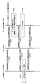
- FIG. 24 is a sequence diagram showing a flow of processing in the configuration shown in FIGS. 22 and 23;
- FIG. 1 is a diagram showing an example of a schematic configuration of an endoscopic surgery system 5000 to which the technology according to the present disclosure can be applied.
- an operator (doctor) 5067 is illustrated operating a patient 5071 on a patient bed 5069 using the endoscopic surgery system 5000.
- the endoscopic surgery system 5000 includes an endoscope 5001, other surgical instruments 5017, a support arm device 5027 for supporting the endoscope 5001, and various devices for endoscopic surgery. And a cart 5037 on which the
- trockers 5025a to 5025d are punctured in the abdominal wall. Then, the barrel 5003 of the endoscope 5001 and other surgical tools 5017 are inserted into the body cavity of the patient 5071 from the trocars 5025 a to 5025 d.
- an insufflation tube 5019, an energy treatment instrument 5021 and a forceps 5023 are inserted into the body cavity of the patient 5071 as the other surgical instruments 5017.
- the energy treatment tool 5021 is a treatment tool that performs incision and peeling of tissue, sealing of a blood vessel, or the like by high-frequency current or ultrasonic vibration.
- the illustrated surgical tool 5017 is merely an example, and various surgical tools generally used in endoscopic surgery, such as forceps and retractors, may be used as the surgical tool 5017, for example.
- An image of a surgical site in a body cavity of a patient 5071 captured by the endoscope 5001 is displayed on the display device 5041.
- the operator 5067 performs a treatment such as excision of the affected area using the energy treatment tool 5021 and the forceps 5023 while viewing the image of the operative part displayed on the display device 5041 in real time.
- a treatment such as excision of the affected area using the energy treatment tool 5021 and the forceps 5023
- the insufflation tube 5019, the energy treatment instrument 5021 and the forceps 5023 are supported by the operator 5067 or an assistant during the operation.
- the support arm device 5027 includes an arm portion 5031 extending from the base portion 5029.
- the arm unit 5031 includes joints 5033 a, 5033 b, 5033 c, and links 5035 a, 5035 b, and is driven by control from the arm control device 5045.
- the endoscope 5001 is supported by the arm unit 5031 and the position and posture thereof are controlled. In this way, stable position fixation of the endoscope 5001 can be realized.
- the endoscope 5001 includes a lens barrel 5003 whose region of a predetermined length from the tip is inserted into a body cavity of a patient 5071 and a camera head 5005 connected to the proximal end of the lens barrel 5003.
- the endoscope 5001 configured as a so-called rigid endoscope having a rigid barrel 5003 is illustrated, but the endoscope 5001 is configured as a so-called flexible mirror having a flexible barrel 5003 It is also good.
- a light source device 5043 is connected to the endoscope 5001, and light generated by the light source device 5043 is guided to the tip of the lens barrel by a light guide extended inside the lens barrel 5003, and an objective The light is emitted to the observation target in the body cavity of the patient 5071 through the lens.
- the endoscope 5001 is assumed to be a perspective endoscope.
- An optical system and an imaging device are provided inside the camera head 5005, and the reflected light (observation light) from the observation target is condensed on the imaging device by the optical system.
- the observation light is photoelectrically converted by the imaging element to generate an electric signal corresponding to the observation light, that is, an image signal corresponding to the observation image.
- the image signal is transmitted as RAW data to a camera control unit (CCU: Camera Control Unit) 5039.
- the camera head 5005 has a function of adjusting the magnification and the focal length by driving the optical system appropriately.
- a plurality of imaging devices may be provided in the camera head 5005 in order to cope with, for example, stereoscopic vision (3D display).
- a plurality of relay optical systems are provided inside the lens barrel 5003 in order to guide observation light to each of the plurality of imaging elements.
- the CCU 5039 is configured by a CPU (Central Processing Unit), a GPU (Graphics Processing Unit), and the like, and centrally controls the operation of the endoscope 5001 and the display device 5041. Specifically, the CCU 5039 subjects the image signal received from the camera head 5005 to various types of image processing for displaying an image based on the image signal, such as development processing (demosaicing processing). The CCU 5039 provides the display device 5041 with the image signal subjected to the image processing. Also, the CCU 5039 transmits a control signal to the camera head 5005 to control the driving thereof.
- the control signal may include information on imaging conditions such as magnification and focal length.
- the display device 5041 displays an image based on the image signal subjected to the image processing by the CCU 5039 under the control of the CCU 5039.
- the endoscope 5001 corresponds to high resolution imaging such as 4K (horizontal pixel number 3840 ⁇ vertical pixel number 2160) or 8K (horizontal pixel number 7680 ⁇ vertical pixel number 4320), and / or 3D display
- the display device 5041 corresponds to each of the display devices, those capable of high-resolution display and / or those capable of 3D display may be used.
- the display device 5041 can have a size of 55 inches or more to obtain a further immersive feeling. Further, a plurality of display devices 5041 different in resolution and size may be provided depending on the application.
- the light source device 5043 is composed of a light source such as an LED (light emitting diode), for example, and supplies the endoscope 5001 with irradiation light when imaging the surgical site.
- a light source such as an LED (light emitting diode)
- the arm control device 5045 is constituted by a processor such as a CPU, for example, and operates in accordance with a predetermined program to control driving of the arm portion 5031 of the support arm device 5027 according to a predetermined control method.
- the input device 5047 is an input interface to the endoscopic surgery system 5000.
- the user can input various instructions and input instructions to the endoscopic surgery system 5000 via the input device 5047.
- the user inputs various information related to surgery, such as physical information of a patient and information on an operation procedure of the surgery, through the input device 5047.
- the user instructs, via the input device 5047, an instruction to drive the arm unit 5031 or an instruction to change the imaging condition (type of irradiated light, magnification, focal length, etc.) by the endoscope 5001. , An instruction to drive the energy treatment instrument 5021, and the like.
- the type of the input device 5047 is not limited, and the input device 5047 may be any of various known input devices.
- a mouse, a keyboard, a touch panel, a switch, a foot switch 5057, and / or a lever may be applied as the input device 5047.
- the touch panel may be provided on the display surface of the display device 5041.
- the input device 5047 is a device mounted by the user, such as a glasses-type wearable device or an HMD (Head Mounted Display), for example, and various types of input according to the user's gesture or line of sight detected by these devices. Is done.
- the input device 5047 includes a camera capable of detecting the motion of the user, and various inputs are performed in accordance with the user's gesture and the line of sight detected from the image captured by the camera.
- the input device 5047 includes a microphone capable of collecting the user's voice, and various inputs are performed by voice via the microphone.
- the user for example, the operator 5067
- the input device 5047 being configured to be able to input various information in a non-contact manner. Is possible.
- the user can operate the device without releasing his / her hand from the operating tool, the convenience of the user is improved.
- the treatment tool control device 5049 controls the drive of the energy treatment instrument 5021 for ablation of tissue, incision, sealing of a blood vessel, and the like.
- the insufflation apparatus 5051 has a gas in the body cavity via the insufflation tube 5019 in order to expand the body cavity of the patient 5071 for the purpose of securing a visual field by the endoscope 5001 and securing a working space of the operator.
- Send The recorder 5053 is a device capable of recording various types of information regarding surgery.
- the printer 5055 is a device capable of printing various types of information regarding surgery in various types such as texts, images, and graphs.
- the support arm device 5027 includes a base portion 5029 which is a base and an arm portion 5031 extending from the base portion 5029.
- the arm unit 5031 includes a plurality of joints 5033 a, 5033 b, and 5033 c and a plurality of links 5035 a and 5035 b connected by the joints 5033 b, but in FIG.
- the structure of the arm unit 5031 is simplified and illustrated. In practice, the shapes, the number and arrangement of the joints 5033a to 5033c and the links 5035a and 5035b, and the direction of the rotation axis of the joints 5033a to 5033c are appropriately set so that the arm 5031 has a desired degree of freedom. obtain.
- the arm unit 5031 may be preferably configured to have six or more degrees of freedom.
- the endoscope 5001 can be freely moved within the movable range of the arm unit 5031. Therefore, the lens barrel 5003 of the endoscope 5001 can be inserted into the body cavity of the patient 5071 from a desired direction. It will be possible.
- the joints 5033 a to 5033 c are provided with an actuator, and the joints 5033 a to 5033 c are configured to be rotatable around a predetermined rotation axis by driving the actuators.
- the drive of the actuator is controlled by the arm control device 5045, whereby the rotation angles of the joint portions 5033a to 5033c are controlled, and the drive of the arm portion 5031 is controlled. Thereby, control of the position and posture of the endoscope 5001 can be realized.
- the arm control device 5045 can control the drive of the arm unit 5031 by various known control methods such as force control or position control.
- the driving of the arm unit 5031 is appropriately controlled by the arm control device 5045 according to the operation input, and
- the position and attitude of the endoscope 5001 may be controlled.
- the endoscope 5001 at the tip of the arm unit 5031 is moved from an arbitrary position to an arbitrary position, the endoscope 5001 can be fixedly supported at the position after the movement.
- the arm unit 5031 may be operated by a so-called master slave method. In this case, the arm unit 5031 can be remotely controlled by the user via the input device 5047 installed at a location distant from the operating room.
- the arm control device 5045 receives the external force from the user, and the actuator of each joint 5033 a to 5033 c is moved so that the arm 5031 moves smoothly following the external force. So-called power assist control may be performed. Accordingly, when the user moves the arm unit 5031 while directly touching the arm unit 5031, the arm unit 5031 can be moved with a relatively light force. Therefore, it is possible to move the endoscope 5001 more intuitively and with a simpler operation, and the convenience of the user can be improved.
- the endoscope 5001 is supported by a doctor called scopist.
- the support arm device 5027 by using the support arm device 5027, the position of the endoscope 5001 can be more reliably fixed without manual operation, so that an image of the operation site can be stably obtained. , Can be performed smoothly.
- the arm control device 5045 may not necessarily be provided in the cart 5037. Also, the arm control device 5045 may not necessarily be one device. For example, the arm control device 5045 may be provided at each joint 5033a to 5033c of the arm 5031 of the support arm device 5027, and the arm control devices 5045 cooperate with one another to drive the arm 5031. Control may be realized.
- the light source device 5043 supplies the endoscope 5001 with irradiation light for imaging the operative part.
- the light source device 5043 is composed of, for example, a white light source configured of an LED, a laser light source, or a combination thereof.
- a white light source is configured by a combination of RGB laser light sources
- the output intensity and output timing of each color (each wavelength) can be controlled with high accuracy. Adjustments can be made.
- the laser light from each of the RGB laser light sources is irradiated on the observation target in time division, and the drive of the imaging device of the camera head 5005 is controlled in synchronization with the irradiation timing to cope with each of RGB. It is also possible to capture a shot image in time division. According to the method, a color image can be obtained without providing a color filter in the imaging device.
- the drive of the light source device 5043 may be controlled to change the intensity of the light to be output at predetermined time intervals.
- the drive of the imaging element of the camera head 5005 is controlled in synchronization with the timing of the change of the light intensity to acquire images in time division, and by combining the images, high dynamic without so-called blackout and whiteout is obtained. An image of the range can be generated.
- the light source device 5043 may be configured to be able to supply light of a predetermined wavelength band corresponding to special light observation.
- special light observation for example, the mucous membrane surface layer is irradiated by irradiating narrow band light as compared with irradiation light (that is, white light) at the time of normal observation using the wavelength dependency of light absorption in body tissue.
- the so-called narrow band imaging is performed to image a predetermined tissue such as a blood vessel with high contrast.
- fluorescence observation may be performed in which an image is obtained by fluorescence generated by irradiation with excitation light.
- a body tissue is irradiated with excitation light and fluorescence from the body tissue is observed (autofluorescence observation), or a reagent such as indocyanine green (ICG) is locally injected into the body tissue while being locally injected. What irradiates the excitation light corresponding to the fluorescence wavelength of the reagent, and obtains a fluorescence image etc. can be performed.
- the light source device 5043 can be configured to be able to supply narrow band light and / or excitation light corresponding to such special light observation.
- FIG. 2 is a block diagram showing an example of the functional configuration of the camera head 5005 and the CCU 5039 shown in FIG.
- the camera head 5005 has a lens unit 5007, an imaging unit 5009, a drive unit 5011, a communication unit 5013, and a camera head control unit 5015 as its functions.
- the CCU 5039 also has a communication unit 5059, an image processing unit 5061, and a control unit 5063 as its functions.
- the camera head 5005 and the CCU 5039 are communicably connected in both directions by a transmission cable 5065.
- the lens unit 5007 is an optical system provided at the connection with the lens barrel 5003.
- the observation light taken in from the tip of the lens barrel 5003 is guided to the camera head 5005 and enters the lens unit 5007.
- the lens unit 5007 is configured by combining a plurality of lenses including a zoom lens and a focus lens.
- the optical characteristic of the lens unit 5007 is adjusted so as to condense the observation light on the light receiving surface of the imaging element of the imaging unit 5009.
- the zoom lens and the focus lens are configured such that the position on the optical axis can be moved in order to adjust the magnification and the focus of the captured image.
- the imaging unit 5009 includes an imaging element and is disposed downstream of the lens unit 5007.
- the observation light which has passed through the lens unit 5007 is condensed on the light receiving surface of the imaging device, and an image signal corresponding to the observation image is generated by photoelectric conversion.
- the image signal generated by the imaging unit 5009 is provided to the communication unit 5013.
- an imaging element which comprises the imaging part 5009 it is an image sensor of a CMOS (Complementary Metal Oxide Semiconductor) type, for example, and a color imaging
- CMOS Complementary Metal Oxide Semiconductor
- photography of the high resolution image of 4K or more may be used, for example.
- an imaging element constituting the imaging unit 5009 is configured to have a pair of imaging elements for acquiring image signals for right eye and left eye corresponding to 3D display.
- the 3D display enables the operator 5067 to more accurately grasp the depth of the living tissue at the operation site.
- the imaging unit 5009 is configured as a multi-plate type, a plurality of lens units 5007 are also provided corresponding to each imaging element.
- the imaging unit 5009 may not necessarily be provided in the camera head 5005.
- the imaging unit 5009 may be provided inside the lens barrel 5003 immediately after the objective lens.
- the drive unit 5011 is configured by an actuator, and moves the zoom lens and the focus lens of the lens unit 5007 along the optical axis by a predetermined distance under the control of the camera head control unit 5015. Thereby, the magnification and the focus of the captured image by the imaging unit 5009 may be appropriately adjusted.
- the communication unit 5013 is configured of a communication device for transmitting and receiving various types of information to and from the CCU 5039.
- the communication unit 5013 transmits the image signal obtained from the imaging unit 5009 to the CCU 5039 via the transmission cable 5065 as RAW data.
- the image signal be transmitted by optical communication in order to display the captured image of the surgical site with low latency.
- the operator 5067 performs the operation while observing the condition of the affected area by the captured image, so for safer and more reliable operation, the moving image of the operation site is displayed in real time as much as possible It is because that is required.
- the communication unit 5013 is provided with a photoelectric conversion module which converts an electrical signal into an optical signal.
- the image signal is converted into an optical signal by the photoelectric conversion module, and then transmitted to the CCU 5039 via the transmission cable 5065.
- the communication unit 5013 also receives, from the CCU 5039, a control signal for controlling the drive of the camera head 5005.
- the control signal includes, for example, information indicating that the frame rate of the captured image is designated, information indicating that the exposure value at the time of imaging is designated, and / or information indicating that the magnification and focus of the captured image are designated, etc. Contains information about the condition.
- the communication unit 5013 provides the received control signal to the camera head control unit 5015.
- the control signal from CCU 5039 may also be transmitted by optical communication.
- the communication unit 5013 is provided with a photoelectric conversion module that converts an optical signal into an electric signal, and the control signal is converted into an electric signal by the photoelectric conversion module and is then provided to the camera head control unit 5015.
- the imaging conditions such as the frame rate, the exposure value, the magnification, and the focus described above are automatically set by the control unit 5063 of the CCU 5039 based on the acquired image signal. That is, so-called AE (Auto Exposure) function, AF (Auto Focus) function, and AWB (Auto White Balance) function are installed in the endoscope 5001.
- AE Auto Exposure
- AF Automatic Focus
- AWB Automatic White Balance
- the camera head control unit 5015 controls the drive of the camera head 5005 based on the control signal from the CCU 5039 received via the communication unit 5013. For example, the camera head control unit 5015 controls the drive of the imaging element of the imaging unit 5009 based on the information to specify the frame rate of the captured image and / or the information to specify the exposure at the time of imaging. Also, for example, the camera head control unit 5015 appropriately moves the zoom lens and the focus lens of the lens unit 5007 via the drive unit 5011 based on the information indicating that the magnification and the focus of the captured image are designated.
- the camera head control unit 5015 may further have a function of storing information for identifying the lens barrel 5003 and the camera head 5005.
- the camera head 5005 can have resistance to autoclave sterilization.
- the communication unit 5059 is configured of a communication device for transmitting and receiving various types of information to and from the camera head 5005.
- the communication unit 5059 receives an image signal transmitted from the camera head 5005 via the transmission cable 5065.
- the image signal can be suitably transmitted by optical communication.
- the communication unit 5059 is provided with a photoelectric conversion module that converts an optical signal into an electrical signal in response to optical communication.
- the communication unit 5059 provides the image processing unit 5061 with the image signal converted into the electrical signal.
- the communication unit 5059 transmits a control signal for controlling driving of the camera head 5005 to the camera head 5005.
- the control signal may also be transmitted by optical communication.
- An image processing unit 5061 performs various types of image processing on an image signal that is RAW data transmitted from the camera head 5005.
- image processing for example, development processing, high image quality processing (band emphasis processing, super-resolution processing, NR (noise reduction) processing and / or camera shake correction processing, etc.), and / or enlargement processing (electronic zoom processing) And various other known signal processings.
- the image processing unit 5061 also performs detection processing on the image signal to perform AE, AF, and AWB.
- the image processing unit 5061 is configured by a processor such as a CPU or a GPU, and the image processing and the detection processing described above can be performed by the processor operating according to a predetermined program.
- the image processing unit 5061 is configured by a plurality of GPUs, the image processing unit 5061 appropriately divides the information related to the image signal, and performs image processing in parallel by the plurality of GPUs.
- the control unit 5063 performs various types of control regarding imaging of the surgical site by the endoscope 5001 and display of the imaged image. For example, the control unit 5063 generates a control signal for controlling the drive of the camera head 5005. At this time, when the imaging condition is input by the user, the control unit 5063 generates a control signal based on the input by the user. Alternatively, when the endoscope 5001 is equipped with the AE function, the AF function, and the AWB function, the control unit 5063 determines the optimum exposure value, focal length, and the like according to the result of the detection processing by the image processing unit 5061. The white balance is appropriately calculated to generate a control signal.
- control unit 5063 causes the display device 5041 to display an image of the operative site based on the image signal subjected to the image processing by the image processing unit 5061.
- control unit 5063 recognizes various objects in the surgical site image using various image recognition techniques. For example, the control unit 5063 detects a shape, a color, and the like of an edge of an object included in an operation part image, thereby enabling a surgical tool such as forceps, a specific living part, bleeding, mist when using the energy treatment tool 5021, and the like. It can be recognized.
- control unit 5063 When the control unit 5063 causes the display device 5041 to display the image of the operation unit, the control unit 5063 superimposes and displays various types of surgery support information on the image of the operation unit, using the recognition result.
- the operation support information is superimposed and presented to the operator 5067, which makes it possible to proceed with the operation more safely and reliably.
- a transmission cable 5065 connecting the camera head 5005 and the CCU 5039 is an electrical signal cable compatible with communication of electrical signals, an optical fiber compatible with optical communication, or a composite cable of these.
- communication is performed by wire communication using the transmission cable 5065, but communication between the camera head 5005 and the CCU 5039 may be performed wirelessly.
- the communication between the two is performed wirelessly, it is not necessary to lay the transmission cable 5065 in the operating room, so that the movement of the medical staff in the operating room can be eliminated by the transmission cable 5065.
- the endoscopic surgery system 5000 to which the technology according to the present disclosure can be applied has been described.
- the endoscopic surgery system 5000 was demonstrated as an example here, the system to which the technique which concerns on this indication can be applied is not limited to this example.
- the technology according to the present disclosure may be applied to a flexible endoscopic system for examination or a microsurgical system.
- the support arm device described below is an example configured as a support arm device that supports the endoscope at the tip of the arm unit, but the present embodiment is not limited to the example.
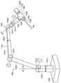
- FIG. 3 is a schematic view showing an appearance of a support arm device 1400 according to the present embodiment.
- the support arm device 1400 includes a base portion 1410 and an arm portion 1420.
- the base 1410 is a base of the support arm device 1400, and the arm 1420 is extended from the base 1410.
- a control unit that integrally controls the support arm device 1400 may be provided in the base unit 1410, and the driving of the arm unit 1420 may be controlled by the control unit.
- the said control part is comprised by various signal processing circuits, such as CPU and DSP, for example.
- the arm unit 1420 includes a plurality of active joint units 1421a to 1421f, a plurality of links 1422a to 1422f, and an endoscope device 423 as a tip unit provided at the tip of the arm unit 1420.
- the links 1422a to 1422f are substantially rod-like members.
- One end of link 1422a is connected to base 1410 via active joint 1421a
- the other end of link 1422a is connected to one end of link 1422b via active joint 1421b
- the other end of link 1422b is an active joint It is connected with one end of the link 1422 c through the portion 1421 c.
- the other end of the link 1422 c is connected to the link 1422 d via the passive slide mechanism 1100
- the other end of the link 1422 d is connected to one end of the link 1422 e via the passive joint 200.
- the other end of the link 1422 e is connected to one end of the link 1422 f via the active joints 1421 d and 1421 e.
- the endoscope apparatus 1423 is connected to the distal end of the arm 1420, that is, the other end of the link 1422f via an active joint 1421f.
- the ends of the plurality of links 1422a to 1422f are connected to one another by the active joints 1421a to 1421f, the passive slide mechanism 1100, and the passive joint 1200, using the base 1410 as a fulcrum.
- An arm shape to be stretched is configured.
- the position and posture of the endoscope apparatus 1423 are controlled by driving and controlling the actuators provided in the active joint sections 1421a to 1421f of the arm section 1420.
- the endoscope apparatus 1423 enters a body cavity of a patient whose distal end is the treatment site, and images a partial region of the treatment site.
- the distal end unit provided at the distal end of the arm unit 1420 is not limited to the endoscope device 1423, and various medical instruments may be connected to the distal end of the arm unit 1420 as a distal end unit.
- the support arm device 1400 according to the present embodiment is configured as a medical support arm device provided with a medical instrument.
- the support arm device 1400 will be described by defining coordinate axes as shown in FIG. Also, according to the coordinate axes, the vertical direction, the longitudinal direction, and the horizontal direction are defined. That is, the vertical direction with respect to the base portion 1410 installed on the floor is defined as the z-axis direction and the vertical direction.
- a direction perpendicular to the z-axis which is a direction in which the arm unit 1420 extends from the base unit 1410 (that is, a direction in which the endoscope device 1423 is positioned with respect to the base unit 1410) It defines as the direction and the front and back direction.
- directions orthogonal to the y-axis and z-axis are defined as x-axis direction and left-right direction.
- the active joints 1421a to 1421f pivotally connect the links to each other.
- the active joint portions 1421a to 1421f have an actuator, and have a rotation mechanism that is rotationally driven with respect to a predetermined rotation axis by driving of the actuator.
- By controlling the rotational drive in each of the active joint portions 1421a to 1421f it is possible to control the drive of the arm portion 1420 such as stretching or contraction (folding) of the arm portion 1420, for example.
- the drive of the active joints 1421a to 1421f can be controlled by, for example, known whole-body coordinated control and ideal joint control.
- the drive control of the active joints 1421a to 1421f specifically refers to the rotation angles of the active joints 1421a to 1421f and And / or means that the generated torque (torque generated by the active joints 1421a to 1421f) is controlled.
- the passive slide mechanism 1100 is an aspect of the passive configuration changing mechanism, and links the link 1422 c and the link 1422 d so as to be able to move back and forth along a predetermined direction.
- the passive slide mechanism 1100 may link the link 1422c and the link 1422d so as to be linearly movable relative to each other.
- the advancing and retracting motion of the link 1422 c and the link 1422 d is not limited to the linear motion, and may be an advancing and retracting motion in a direction forming an arc.
- the passive slide mechanism 1100 for example, the user performs an operation of advancing and retracting, and the distance between the active joint portion 1421c on one end side of the link 1422c and the passive joint portion 1200 is variable. This may change the overall configuration of the arm 1420. Details of the configuration of the passive slide mechanism 1100 will be described later.
- the passive joint 1200 is an aspect of the passive deformation mechanism, and pivotally connects the link 1422 d and the link 1422 e to each other.
- the user performs a turning operation to change the angle between the link 1422d and the link 1422e. This may change the overall configuration of the arm 1420. Details of the configuration of the passive joint 1200 will be described later.
- the attitude of the arm portion means the active joint portions 1421 a to 1421 f by the control portion in a state in which the distance between the active joint portions adjacent to each other across one or more links is constant.
- the state of the arm unit that can be changed by the drive control of the actuator provided in
- the form of the arm unit refers to the distance between the active joints adjacent to each other across the link or the link connecting the active joints adjacent to each other as the passive form changing mechanism is operated. It refers to the state of the arm part that can be changed by changing the angle between the two.
- the support arm device 1400 has six active joint portions 1421a to 1421f, and six degrees of freedom are realized in driving the arm portion 1420. That is, the drive control of the support arm device 1400 is realized by the drive control of the six active joints 1421a to 1421f by the controller, while the passive slide mechanism 1100 and the passive joint 1200 are the targets of the drive control by the controller. is not.
- the active joint portions 1421a, 1421d, 1421f rotate the long axis direction of the connected links 1422a, 1422e and the photographing direction of the connected endoscope apparatus 1423. It is provided to be in the axial direction.
- the active joint parts 1421b, 1421c, 1421e are each connected to the links 1422a to 1422c, 1422e, 1422f, and the connecting angle of the endoscope apparatus 423 in the yz plane (a plane defined by the y axis and the z axis) It is provided so that the x-axis direction, which is the direction to be changed inside, is the rotation axis direction.
- the active joints 1421a, 1421d, and 1421f have a function of performing so-called yawing
- the active joints 1421b, 1421c, and 1421e have a function of performing so-called pitching.
- a hemisphere is illustrated as an example of the movable range of the endoscope apparatus 1423.
- RCM remote movement center
- the arm 1420 may have a degree of freedom 1421 g for rotating the endoscope apparatus 1423 coaxially with the link 1422 f.
- the endoscope apparatus 1423 can be rotated with the longitudinal axis of the link 1422 f as a rotation axis.
- FIG. 4 is a block diagram showing an example of the overall configuration of a support arm device 1400 including a control device 1350.
- the control device 1350 includes a control unit 1351, a storage unit 1357, and an input unit 1359.
- the control unit 1351 is configured of, for example, various signal processing circuits such as a CPU and a DSP.
- the control unit 1351 integrally controls the control device 1350 and performs various calculations for controlling the drive of the arm unit 1420 in the support arm device 1400.
- the control unit 1351 includes a whole body coordination control unit 1353 and an ideal joint control unit 1355.
- the whole body coordination control unit 1353 performs various calculations in whole body coordination control in order to drive and control the actuators 1430 provided in the active joints 1421 a to 1421 f of the arm unit 1420 of the support arm device 1400.
- the ideal joint control unit 1355 performs various calculations in the ideal joint control that realizes an ideal response to the whole-body coordinated control by correcting the influence of the disturbance.
- the storage unit 1357 may be, for example, a storage element such as a random access memory (RAM) or a read only memory (ROM), or may be a semiconductor memory, a hard disk, or an external storage device.
- RAM random access memory
- the input unit 359 is an input interface for the user to input information, commands, and the like regarding drive control of the support arm device 400 to the control unit 351.
- the input unit 359 has, for example, operation means operated by the user such as a lever, a pedal, etc., and the position, speed, etc. of each component of the arm unit 420 are instantaneous motion according to the operation of the lever, pedal etc It may be set as a purpose.
- the input unit 359 may include, for example, an operation unit operated by the user such as a mouse, a keyboard, a touch panel, a button, and a switch, in addition to a lever and a pedal.
- the arm unit 1420 controlled by the control device 1350 includes an active joint unit 1421.
- the active joint portion 1421 (1421a to 1421f) has various configurations necessary for driving the arm portion 1420, such as a support member for connecting or supporting the links 1422a to 1422f and the endoscope apparatus 1423.
- the drive of the joint of the arm 1420 may mean the drive of the actuator 430 in the active joints 1421a to 1421f.
- the active joint 1421 includes a torque sensor 1428, an encoder 1427 and an actuator 1430. Although the actuator 1430, the encoder 1427, and the torque sensor 1428 are shown separately in FIG. 4, the encoder 1427 and the torque sensor 1428 may be included in the actuator 1430.
- the actuator 1430 is composed of a motor, a motor driver, and a reduction gear.
- the actuator 1430 is, for example, an actuator corresponding to force control.
- the rotation of the motor is decelerated by the reduction gear at a predetermined reduction ratio, and is transmitted to another member in the subsequent stage via the output shaft, whereby the other member is driven.
- the motor is a drive mechanism that produces a rotational drive force.
- the motor is driven to generate torque corresponding to a torque command value from the control unit under control of the motor driver.
- a brushless motor is used as the motor.
- the present embodiment is not limited to this example, and various known types of motors may be used as the motor.
- the motor driver is a driver circuit (driver IC (Integrated Circuit)) that rotationally drives the motor by supplying current to the motor, and controls the number of rotations of the motor by adjusting the amount of current supplied to the motor. Can.
- the motor driver drives the motor by supplying a current corresponding to the torque command value ⁇ from the control unit to the motor.
- the motor driver can also adjust the viscous drag coefficient in the rotational movement of the actuator 1430 by adjusting the amount of current supplied to the motor. This makes it possible to apply a predetermined resistance to the rotational movement of the actuator 1430, that is, the rotational movement of the active joint portions 1421a to 1421f.
- the active joint portions 1421a to 1421f can be set in a state in which they can easily rotate with respect to an externally applied force (that is, a state in which the arm portion 1420 can be easily moved manually). It is also possible to make it difficult to rotate with respect to the force (that is, a state in which it is difficult to move the arm 1420 manually).
- a reduction gear is connected to the rotation shaft (drive shaft) of the motor.
- the reduction gear decelerates the rotational speed of the rotation shaft of the connected motor (that is, the rotation speed of the input shaft) at a predetermined reduction ratio and transmits it to the output shaft.
- the configuration of the reduction gear is not limited to a specific one, and various kinds of known reduction gears may be used as the reduction gear.
- the reduction gear it is preferable to use, for example, a harmonic drive (registered trademark) or the like that can set the reduction ratio with high accuracy.
- the reduction gear ratio of the reduction gear can be appropriately set according to the application of the actuator 1430.
- a reduction gear having a reduction ratio of about 1: 100 can be suitably used.
- the encoder 1427 detects the rotation angle of the input shaft (ie, the rotation angle of the rotation shaft of the motor). Based on the number of rotations of the input shaft detected by the encoder 1427 and the reduction ratio of the reduction gear, information such as the rotation angle, rotation angular velocity, and rotation angular acceleration of the active joint portions 1421a to 1421f can be obtained.
- the encoder 1427 for example, various known rotary encoders such as a magnetic encoder and an optical encoder may be used.
- the encoder 1427 may be provided only on the input shaft of the actuator 1430, or an encoder for detecting the rotation angle or the like of the output shaft of the actuator 1430 may be further provided downstream of the reduction gear.
- the torque sensor 1428 is connected to the output shaft of the actuator 1430 and detects a torque acting on the actuator 1430.
- the torque sensor 1428 detects a torque (generated torque) output by the actuator 1430.
- the torque sensor 1428 can also detect an external torque applied to the actuator 1430 from the outside.
- the operation of the arm unit 1420 is controlled by force control.
- the rotation angle of each active joint 1421a to 1421f and the torque acting on each active joint 1421a to 1421f by the encoder 1427 and the torque sensor 1428 provided for each actuator 1430. are detected respectively.
- the torque acting on each of the active joint portions 1421a to 1421f detected by the torque sensor 1428 may include the force acting on the arm portion 1420 and / or the endoscope apparatus 1423.
- the current state (position, speed, etc.) of the arm unit 1420 may be acquired.
- a torque to be generated by 1430 is calculated, and the actuator 1430 of each of the active joint portions 1421a to 1421f is driven with the torque as a control value.
- actuator 1430 various known actuators generally used in various devices whose operation is controlled by force control can be used.
- the actuator 1430 those described in Japanese Patent Application Laid-Open Nos. 2009-269102 and 2011-209099, which are prior patent applications filed by the present applicant, can be suitably used.
- the configuration of the actuator 1430 and each component constituting the actuator is not limited to the above configuration, and may be another configuration.
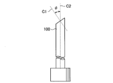
- FIG. 5 is a schematic view showing the appearance of the oblique endoscope 100.
- the direction (C1) of the objective lens to the subject has a predetermined angle ⁇ with respect to the longitudinal direction (scope axis C2) of the oblique mirror 100. That is, in the oblique endoscope 100, the objective optical system forms an angle with the eyepiece optical system of the scope.
- oblique rotation an operation of rotating the oblique endoscope 100 with the scope axis C2 as a rotation axis (hereinafter, referred to as oblique rotation) is performed for observation.
- oblique rotation By performing oblique rotation, it is possible to obtain a circling visual field and peripheral visual fields in the top, bottom, left, and right.
- FIG. 6 is a schematic view showing how the visual field 200 displayed on the display device 5041 is changed by oblique rotation.
- the field of view 200 displayed on the monitor if the oblique view is rotated by the oblique view rotation angle ⁇ to control the vertical direction of the field of view 200, the field of view displayed on the monitor will be the field of view 200 Change to a field of view 200 '. Therefore, by controlling the oblique rotation and the two axes in the vertical direction of the camera, the upper, lower, left, and right peripheral vision can be obtained.
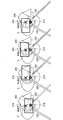
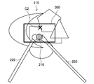
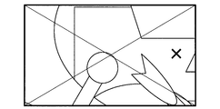
- FIG. 7 is a schematic view showing how the visual field displayed on the monitor is changed by oblique rotation.
- FIG. 7 shows a state in which the inside of the body is observed with a perspective endoscope, and shows a state in which an observation object 210 which a user (operator) tries to look at is present in various organs 215.
- the visual field 200 of the monitor is shown as a rectangular area, and the observation object 210 and the scope axis C2 which the user (operator) tries to look at are shown together with the visual field 200.
- FIG. 7 shows a state in which the operator brings a surgical tool 220 such as forceps into contact with the observation object 210 and holds the observation object 210 or the like.
- FIG. 7 shows how the observation object 210 moves with respect to the field of view 200 when the oblique endoscope 100 is rotated about the scope axis C2.
- FIG. 7 shows a state of “under oblique view” in which the optical axis of the oblique view objective 100 is directed downward in the vertical direction of the field of view 200.
- the observation object 210 enters the visual field 200, and the operator can visually recognize the observation object 210 on the monitor.
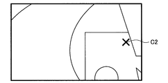
- the “right oblique” view shown in FIG. 7 shows a state in which the optical axis of the oblique view objective 100 is directed to the right in the lateral direction of the field of view 200.
- the observation object 210 deviates from the visual field 200, and the operator can not visually recognize the observation object 210 on the monitor.
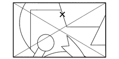
- the view “on oblique view” shown in FIG. 7 shows a state in which the optical axis of the objective optical system of the oblique view mirror 100 is directed upward in the vertical direction of the field of view 200. Further, in the “left oblique” view shown in FIG. 7, the optical axis of the oblique view objective 100 is directed to the left side in the left-right direction of the field of view 200. Also in these cases, the observation object 210 deviates from the visual field 200, and the operator can not view the observation object 210 on the monitor.
- the position of the field of view with respect to the observation object 210 can be changed by performing oblique rotation, and a relatively wide range around the scope axis C2 can be visually recognized.
- FIG. 7 there is a possibility that a portion or instrument that the user wants to see may deviate from the visual field 200 of the monitor due to the oblique rotation, and may lose sight of those places.
- the position of the observation object 210 is detected, and the arm is controlled so that the observation object 210 moves to the center of the screen.
- the rotational speed at the time of oblique rotation is changed according to the position of the observation object 210 with respect to the visual field 200. Specifically, control is performed such that the rotational speed at the time of oblique rotation is slower as the observation target object 210 is farther from the center of the field of view 200. As the observation target object 210 moves away from the center of the field of view 200, the observation target object 210 is more likely to be out of the field of view 200 when oblique rotation is performed.
- the rotational speed at the time of oblique view rotation is reduced, so that the observation object 210 is less likely to come out of the field 200, and the position of the observation object 210 is lost Will be suppressed.
- the follow-up function and the oblique view rotation speed are different, it is possible for the screen to move out of the screen unless the movement speed of freedom to move the screen vertically and horizontally and the oblique view rotation speed is coordinated. There is sex. For this reason, while controlling so that the observation object 210 is at the center of the screen, the speed of oblique rotation is controlled to be reduced according to the distance L from the center of the screen to the object 21 or the relative position.
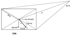
- FIG. 8 is a schematic view showing a method of calculating the distance from the center of the visual field 200 to the observation object 210.
- the oblique rotation speed is ⁇ [rad / s]
- the number of pixels from the screen center O to the position p of the observation object 210 is (x, y) [pixels]
- FIG. 9 is a schematic view showing an example of a map that defines the speed of oblique rotation in accordance with the position of the subject in the screen.
- the map 400 shows an example based on FIG. 8 in which the speed of oblique rotation is reduced as the distance from the screen center O increases.
- the density of dots on the map 400 corresponds to the speed of oblique rotation
- the map 410 shows the relationship between the density of dots on the map 400 and the speed of oblique rotation. As shown in the map 410, the higher the dot density, the faster the oblique rotation speed. Therefore, in the map 400, as the distance from the screen center O increases, the speed of oblique rotation decreases.
- the graph also shows the relationship between the density of dots, the speed of oblique rotation, and the distance to the subject (observation target 210).
- the speed of oblique rotation is lower as the distance to the object is shorter. The closer the distance to the subject, the more the amount of movement of the observation object 210 in the field of view 200 according to the movement of the oblique endoscope 100. Therefore, as the distance to the subject decreases, the speed of oblique rotation decreases. It is possible to prevent the observation object 210 from being lost from 200.
- FIG. 10 is a characteristic diagram showing the relationship between the distance from the screen center O to the observation object 210 (horizontal axis) and the oblique rotation speed (vertical axis). As described above, the control is performed so that the speed of oblique rotation decreases as the distance from the screen center O to the observation object 210 increases, but variations as illustrated in FIG. 10 can be assumed as a control method.
- control is performed with priority given to the speed of oblique rotation. If the movement of the arm in the X and Y directions is fast enough, tracking of the observation object 210 is possible even with such characteristics. Since the rotational speed of the oblique endoscope is not 0 even at the screen end (Lmax), depending on the position of the observation object 210 at the start of oblique rotation, the observation object 210 may deviate from the screen.
- the observation object 210 is never removed from the visual field 200 when the XY movement is very slow.
- the observation object 210 deviates to some extent from the screen center O, the oblique rotation is completely stopped and only the XY movement is performed.
- FIG. 11 shows a state in which the direction of the optical axis of the objective optical system is changed by the rotation (the oblique rotation) of the center of the long axis of the oblique endoscope 100.
- the visual field also moves as described in FIG.
- FIG. 10 although it is possible to change the direction in which the operator looks by oblique rotation, the visual field also moves as described in FIG.
- FIG. 10 although it is possible to change the direction in which the operator looks by oblique rotation, the visual field also moves as described in FIG. On the other hand, FIG.
- a trocker point shall mean the position where a trocar is inserted in a human body.
- a rotational movement a movement of the oblique view pivot
- the oblique view rotation angle can be changed without removing the field of view.
- FIG. 13 shows an example of parallel movement without changing the posture of the oblique endoscope, and is a schematic view showing a case where oblique movement is performed along with the movement of parallel movement. In this case, the movement is performed without changing the posture of the oblique endoscope 100 with respect to the camera field of view.
- Oblique view angle ⁇ (around Y axis), oblique view rotation angle ⁇ (around Z axis), rigidoscope length L, distance R to the object to be observed, point V at the center of the visual field, amount of parallel movement (ax, ay, az) Then, the simultaneous transformation matrix representing translation is as follows.
- the simultaneous conversion matrix of the oblique angle and the oblique rotation angle can be expressed as follows.
- the initial position of the rigid scope root is set as the origin of (0, 0, 0) for simplification.
- the point V at the center of the field of view is as follows.
- the field of view can be moved by the same amount as the rigid mirror is moved in parallel.
- ax and ay according to the value of ⁇ so as to keep V constant, it is possible to keep looking at the target point while performing oblique rotation as shown in FIG.
- the amount of change of (ax, ay) to move V in order to keep the position constant is faster than the amount of change of (R cos ⁇ ⁇ , R sin ⁇ sin ⁇ )
- the object will not be out of view by the rotation of the oblique endoscope.
- the oblique rotation speed is controlled, it is possible to rotate the oblique without losing the object from the screen.
- the relative movement of (Rcos ⁇ ⁇ , Rsin ⁇ sin ⁇ ) and (ax, ay) affects the same movement by adjusting the speed of (ax, ay) in addition to the speed of the oblique rotation angle.
- Such a movement is limited to the case where there is no restriction of the trocar point, and corresponds to, for example, the case of a strabismus operation with a small thoracotomy / small incision in the chest. Because the motion is in the Y direction, the distance between the field of view 200 and the camera is maintained.
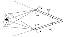
- FIG. 14 shows an example in which the field of view is moved in the vertical and horizontal directions by rotation around the constraining point 300.
- the restraint point 300 corresponds to, for example, a trocker point.
- the configuration of the arm can be realized with three degrees of freedom centered on the restraint point 300. Assuming that the rotation about the X axis around the constraining point 300 is ⁇ , and the rotation around the Y axis is ⁇ , each rotation matrix is as follows.
- the simultaneous transformation matrix of rotation about the constraint point 300 is as follows.
- the point V at the center of the field of view can be expressed as follows.
- the target values of ⁇ and ⁇ are selected so as to maintain the value of V.
- control can be performed without removing the object from the field of view even in the process of following the target value by adjusting the above-mentioned oblique rotation angle. It becomes possible.
- a control method of an arm may be used in which the position of the object in the screen is recognized by image recognition or the like and the observation object is moved in the screen based on the information.
- the support arm device is controlled such that the object present inside the patient's human body coincides with the optical axis of the endoscope attached to the support arm device and inserted into the patient's human body.
- an information processing apparatus comprising: a control unit for moving the endoscope. By controlling the arm so that the object appears at the screen center by recognizing the object by image recognition etc., it is possible to capture the object such as a surgical instrument or a tumor at the center of the image obtained by the endoscope The convenience of the operator is improved.
- Such an information processing apparatus may be configured separately from the endoscopic surgery system 5000, or may be configured as any device included in the endoscopic surgery system 5000.
- FIG. 15 and FIG. 16 are diagrams for explaining the outline of the present embodiment.
- FIG. 15 shows a state in which the barrel 5003 of the endoscope 5001 is inserted into the body cavity of the patient 5071 from the trocar 5025a punctured in the abdominal wall of the patient 5071.
- the endoscope 5001 indicated by a solid line indicates the current position and orientation
- the endoscope 5001 indicated by a broken line is a movement destination (i.e., the future) by the endoscope control processing according to the present embodiment. ) Shows the position and posture.
- forceps 5023 are inserted from the trocar 5025d punctured into the abdominal wall of the patient 5071.
- FIG. 15 shows a state in which the barrel 5003 of the endoscope 5001 is inserted into the body cavity of the patient 5071 from the trocar 5025a punctured in the abdominal wall of the patient 5071.
- an image (hereinafter also referred to as an endoscopic image) obtained by the endoscope 5001 shown in FIG. 15 is shown, and the left drawing is an image obtained at the current position and orientation, and the right drawing is It is an image obtained after movement by endoscope control processing concerning this embodiment.
- the tip of the forceps 5023 is captured within the field of view 6052 of the endoscope 5001 but not on the central axis (that is, the optical axis) 6051 . Therefore, as shown in the left view of FIG. 16, an endoscopic image in which the tip of the forceps 5023 is not shown at the center can be obtained.
- the endoscopic surgery system 5000 according to the present embodiment performs a process of moving the endoscope 5001 so that a surgical tool such as the forceps 5023 appears at the center of the screen.
- the endoscopic surgery system 5000 moves the endoscope 5001 by the support arm device 5027 (not shown) so that the tip of the forceps 5023 is positioned on the central axis 6051.
- the endoscope image in which the tip of the forceps 5023 appears at the center is obtained.
- the control of the oblique view 200 is considered by considering the oblique angle and the oblique rotation angle. It can be performed.
- the tip of the forceps 5023 is positioned on the central axis 6051
- the case where the observation target 210 is positioned on the central axis 6051 as a target by image recognition of the observation target 210 is similarly performed. be able to.
- the endoscopic surgery system 5000 can automatically follow the surgical instrument to provide an endoscopic image in which the surgical instrument is displayed at the center of the screen. Therefore, the operator can comfortably continue the operation without operating the endoscope 5001.
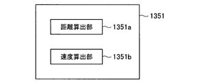
- FIG. 21 is a schematic view showing the configuration of the control unit 1351 of the support arm device 1400 for performing the above-described oblique rotation operation and follow-up operation.
- the control unit 1351 obtains a distance from the center of the visual field to the position of the observation object 210 in the visual field 200 obtained by imaging the observation object 210, and the visual field And a speed calculation unit 1351b that calculates the speed of oblique rotation of the oblique view 100 or the movement speed of the oblique view 100 based on the distance from the center of the object to the position of the observation object 210. Acquisition of the distance from the center of the field of view by the distance acquisition unit 1351a to the position of the observation object 210 is performed based on the result of image recognition of the observation object 210 by the control unit 5063 of the CCU 5039.
- control unit 1351 controls the support arm apparatus 1400 so that the observation target object 210 is positioned at the center of the field of view 200 based on the result of the control unit 5063 of the CCU 5039 performing image recognition of the observation target object 210. At this time, the control unit 1351 controls at least one of the speed of oblique rotation of the oblique view 100 and the movement speed of the oblique view 100 according to the position of the observation object 210 in the field of view 200. The control unit 1351 controls the rotation angle and the rotation speed of the oblique endoscope 100 around the long axis in accordance with the position of the observation target 210 in the field of view 200.
- control unit 5063 of the CCU 5039 can recognize the features of the image of the observation object 210 and the position in the field of view 200 using various image recognition techniques.
- the control unit 1351 acquires, from the CCU 5039, information on the position of the observation object 210 in the field of view 200.
- the operator can designate the observation object 210 from the operation site displayed on the display device 5041 by operating the input device 5047 while viewing the image of the operation site displayed on the display device 5041 in real time .
- the control unit 5063 recognizes the feature of the image of the observation target 210 and the position in the field of view 200 based on the designated observation target 210.
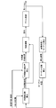
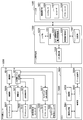
- FIG. 17 is a diagram for describing an overview of endoscope control processing according to the present embodiment.
- Each block shown in FIG. 17 shows a process, and the endoscope control process consists of a plurality of processes.
- the endoscopic surgery system 5000 performs image processing to detect a target such as a surgical instrument. Then, the endoscopic surgery system 5000 calculates the position of the target based on the detection result. Next, the endoscopic surgery system 5000 calculates the current posture of the endoscope based on the calculated target position and trocar position. Next, the endoscopic surgery system 5000 calculates a target endoscope tip position based on the calculated current posture of the endoscope and the setting information of the virtual surface (flat surface or curved surface).
- the endoscopic surgery system 5000 calculates the amount of change in the posture of the endoscope based on the current posture of the endoscope and the position of the tip of the endoscope to be a target, and the calculated amount of change
- the control information (i.e., command) of the arm for realizing the posture change is generated.
- the endoscopic surgery system 5000 controls the support arm (for example, the arm unit 5031) to operate according to the generated command.
- the endoscopic surgery system 5000 repeatedly performs the series of processes described above.
- the endoscopic surgery system 5000 can implement
- a calculation method will be described in which the arm operates the endoscope from the image processing portion (marker detection) and the detection result to move the tool to the center of the screen while considering the trocker point.
- the endoscopic surgery system 5000 detects a surgical tool (for example, the tip position and / or posture of the surgical tool) by image processing.
- a surgical tool for example, the tip position and / or posture of the surgical tool
- the position of the surgical instrument may be detected by image processing based on the endoscopic image. It is desirable that the marker be easy to detect.
- the marker may be a color such as blue or green that is noticeable compared to the color of an organ or blood vessel in a body cavity (for example, a color located opposite to the color of an organ or blood vessel in a color wheel).
- the marker may be a specific pattern such as a two-dimensional code or a barcode.
- the position of the surgical instrument is detected based on the detection result of the marker by the external sensor and information such as the length and posture of the surgical instrument.
- the detection of the surgical tool may be performed by a method other than image processing.
- the position of the surgical tool may be calculated based on the insertion amount of the surgical tool and the angle of the trocar.
- the position of the surgical instrument may be calculated from the position and orientation information of the support arm apparatus by attaching the surgical instrument to a support arm apparatus other than the endoscope.
- Target calculation The endoscopic surgery system 5000 performs target calculation.
- the target calculation is a calculation for calculating two of the position and the posture and instructing movement.
- the endoscopic surgery system 5000 first determines the target position from the image processing result, and then determines the amount of change in posture based on the current posture starting from the trocker point and the posture at the time the target position is reached. Do. In addition, the endoscopic surgery system 5000 performs target calculation based on the current position and orientation acquired from the encoder while obtaining the movement amount from the result of the image processing, but in the case of performing an actual instruction, The calculated command value is added to the command value. The reason for this is that there is a gap between the current value and the command value due to a control error, and if the goal is set with the current value as the starting point when issuing the command value, the operation is not smooth, and This is because a problem occurs in which the error increases.
- FIG. 18 is a flow chart showing an example of the flow of target calculation processing by the endoscopic surgery system 5000 according to the present embodiment. As shown in FIG. 18, the endoscopic surgery system 5000 first performs coordinate calculation.
- the endoscopic surgery system 5000 first calculates coordinates based on the current value. Specifically, the endoscopic surgery system 5000 acquires an image processing result (step S402). Then, the endoscopic surgery system 5000 converts the detected position into the camera coordinate system (ie, 2D to 3D conversion) (step S404). Next, the endoscopic surgery system 5000 converts the camera coordinate system into the world coordinate system (step S406). Next, the endoscopic surgery system 5000 converts the trocker point into a unit vector (step S408). Next, the endoscopic surgery system 5000 obtains the length up to the intersection with the predetermined plane (that is, the virtual plane) (step S410). Next, the endoscopic surgery system 5000 converts the vector from the trocker point to the predetermined plane to the World coordinate system (step S412).
- the endoscopic surgery system 5000 converts the vector from the trocker point to the predetermined plane to the World coordinate system (step S412).
- the endoscopic surgery system 5000 calculates coordinates based on the command value after calculating coordinates based on the current value. Specifically, the endoscopic surgery system 5000 converts the endoscope length into the insertion depth (step S414).
- the endoscopic surgery system 5000 After coordinate calculation, the endoscopic surgery system 5000 performs posture calculation.
- the endoscopic surgery system 5000 first calculates the posture based on the current value. Specifically, the endoscopic surgery system 5000 acquires a current posture vector (step S416). Next, the endoscopic surgery system 5000 obtains the calculated attitude of the new target vector (step S418). Next, the endoscopic surgery system 5000 determines the amount of change in posture relative to the calculated new target vector (step S420).
- the endoscopic surgery system 5000 calculates the posture based on the command value after calculating the posture based on the current value. Specifically, the endoscopic surgery system 5000 converts the final command value into a posture change amount from the posture (step S422).
- the endoscopic surgery system 5000 obtains the target position and the target posture.
- FIG. 19 is a diagram for describing target position calculation according to the present embodiment.
- the position viewed from the camera coordinate system with the screen center of the camera tip set to (0.5, 0.5) is normalized to [0.0-1.0].
- the depth is, for example, 50 [mm] at the time of conversion, and combined with the angle of view. Do.
- the reason why the depth is assumed to be 50 [mm] will be described.
- the first reason is that if the assumed value is larger than the actual value, the movement amount of (x, y) becomes larger than the actual (x, y) and overruns (oscillates).
- the second reason is that the imaging distance in the assumed technique is set to 50 [mm] to 100 [mm] to set the shortest distance.
- the third reason is that if the actual distance is larger, the movement is determined from the residual in the next image processing result, and the goal can finally be reached.
- the endoscopic surgery system 5000 obtains a target posture after the target position is determined.
- the control unit 1351 controls the arm unit 1420 by the arm unit based on the target position and the target attitude.
- FIGS. 20A to 20D are schematic views for explaining a specific example in the case where the oblique view is directed to the left by the control of the oblique endoscope according to the present embodiment. Also in FIGS. 20A to 20D, as in FIG. 7, a state in which the observation target object 210 which the user (operator) tries to look at is present in various organs 215 is shown.
- FIG. 20A shows a state (state under oblique view) in which the optical axis of the objective optical system is directed to the lower side of the field of view 200 (the side of the operator who operates the surgical tool 220) with respect to the position of the scope axis C. It shows.
- FIG. 20A shows a state (state under oblique view) in which the optical axis of the objective optical system is directed to the lower side of the field of view 200 (the side of the operator who operates the surgical tool 220) with respect to the position of the scope axis C. It shows.
- FIG. 20A shows
- FIG. 20B is an enlarged view of the visual field 200 of FIG. 20A.
- observation object by oblique rotation compared to FIG. While the left side of the object 210 can be observed, the observation object 210 disappears.
- Example of providing a holding unit to independently control the rotation of the oblique endoscope >>
- the posture and the position of the oblique endoscope 100 are changed only by control of the active joint portions 1421a to 1421f of the arm portion 1420.
- a holding unit with a built-in actuator may be provided at the tip of the arm 1420 to independently control the rotation of the oblique endoscope.
- the rotation of the oblique endoscope 100 is performed by the holding unit, and the position of the entire oblique endoscope and the posture with respect to the operation unit can be controlled by the active joint of the arm.
- FIG. 22 is a schematic view showing a configuration in which a holding unit 7000 for independently controlling the rotation of the oblique view mirror 100 and the rotation of the camera head 7100 is provided at the tip of the arm portion 1420 in the configuration example shown in FIG. .
- the holding unit 7000 is attached to the endoscope unit attachment portion 7300 at the tip of the arm portion 1420, and comprises a camera head attachment portion 7100, a camera head rotation drive portion 7200, a perspective endoscope attachment portion 7400, and a perspective rotation drive portion 7500. There is.
- the camera head 5005 is attached to the camera head rotation drive unit 7200 via the camera head attachment unit 7100.
- the camera head rotation drive unit 7200 includes an actuator 7210 such as a motor, and rotates the camera head 5005 with respect to the endoscope unit attachment unit 7300 and the main body of the holding unit 7000.
- the oblique endoscope 100 is attached to the oblique rotation drive unit 7500 via the oblique attachment unit 7400.
- the oblique endoscope rotation drive unit 7500 includes an actuator 7510 such as a motor, and rotates the oblique endoscope 100 about its axis with respect to the endoscope unit attachment unit 7300 and the main body of the holding unit 7000.
- FIG. 23 is a schematic view showing a configuration of a support arm apparatus 1400 including an arm unit 1420 and a control device 1350, and a configuration of an endoscope unit 5006 and a CCU 5039 in the configuration example shown in FIG.
- the control device 1350 is provided with a CCU communication unit 1358 which communicates with the CCU 5039 in addition to the configuration shown in FIG.
- the CCU 5039 includes an arm communication unit 5064 that communicates with the control device 1350.
- the control device 1350 and the CCU 5039 can transmit and receive information to each other as the CCU communication unit 1358 and the arm communication unit 5064 communicate.
- the endoscope unit 5006 is obtained by adding the function of the holding unit 7000 to the camera head 5005 shown in FIG. 2, and instead of the control unit 5015 shown in FIG. Is equipped.
- the endoscope unit 5006 includes a perspective control unit (first control unit) 5016, a camera head control unit (second control unit) 5017, and a perspective rotation drive unit A camera head rotation drive unit 7200 is provided.
- the perspective control unit 5016 and the camera head control unit 5017 may be provided in the holding unit 7000.
- the functions of the endoscope unit control unit 5014, the oblique view control unit 5016, and the camera head control unit 5017 may be provided to the control unit 1351 of the control device 1350.
- the oblique view control unit 5016 drives the actuator 7510 based on a command from the endoscope unit control unit 5014.
- the actuator 7510 and the oblique rotation unit encoder 7520 are provided in the oblique endoscope rotation drive unit 7500.
- the endoscope unit control unit 5014 drives the actuator 7510 based on the rotation angle of the actuator 7510 detected by the oblique rotation unit encoder 7520 to control the rotation of the oblique endoscope 100 about the axis.
- the camera head control unit 5017 drives the actuator 7210 based on the command of the endoscope unit control unit 5014.
- the actuator 7210 and the camera head rotation unit encoder 7220 are provided in the camera head rotation drive unit 7200.
- the endoscope unit control unit 5014 controls the rotation around the axis of the camera head 5005 based on the rotation angle of the actuator 7210 detected by the camera head rotation unit encoder 7220.
- the oblique endoscope 100 and the camera head 5005 can rotate independently with respect to the endoscope unit attachment portion 7300.
- the oblique endoscope 100 can be rotated to visually recognize a desired observation target, and the camera head 5005 can be rotated to appropriately control the top and bottom of the image.
- FIG. 24 is a sequence diagram showing the flow of processing in the configuration shown in FIGS. 22 and 23.
- step S502 information about the oblique rotation of the oblique endoscope 100 and the attitude of the camera head 5005 in the vertical direction control is sent from the endoscope unit to the CCU 5039.
- step S504 the CCU 5039 sends information on the oblique rotation of the oblique view mirror 100 and the attitude of the top and bottom control of the camera head 5005 to the arm control device.
- step S506 an arm control command and a drive command value of the endoscope unit are calculated.
- step S508 the drive command value of the endoscope unit is sent from the arm control device to the CCU 5039 together with the drive command.
- step S510 the arm is controlled based on the arm control command.
- step S512 the drive command value of the endoscope unit is sent from the CCU 5039 to the endoscope unit together with the drive command.
- step S514 the endoscope unit is controlled based on the drive command value.
- next step S5166 information on the oblique rotation of the oblique endoscope 100 and the attitude of top-bottom control of the camera head 5005 is sent from the endoscope unit to the CCU 5039.
- the CCU 5039 sends information on the oblique rotation of the oblique view mirror 100 and the attitude of the top and bottom control of the camera head 5005 to the arm control device.
- next step S510 information on the oblique rotation of the oblique view mirror 100 and the attitude of the top and bottom control of the camera head 5005 is sent from the endoscope unit to the CCU 5039.
- the CCU 5039 sends information on the oblique rotation of the oblique view mirror 100 and the attitude of the top and bottom control of the camera head 5005 to the arm control device.
- the image recognition of the observation object 210 existing inside the human body of the patient is performed, and the position of the observation object 210 coincides with the optical axis of the objective optical system of the oblique endoscope 100.
- the arm is controlled to move the endoscope while restraining the tip of the endoscope on a virtual surface. This makes it possible to capture the observation object 210 such as a surgical instrument or a tumor in the center of the visual field 200 when the oblique vision rotation is performed, and the convenience of the operator is improved.
- the operator can perform the oblique rotation while maintaining the part to be seen, the instrument, etc. constantly in the screen, and it is possible to suppress the observation object 210 from being lost by the oblique rotation.
- each device described in the present specification may be realized using any of software, hardware, and a combination of software and hardware.
- the programs that configure the software are stored in advance in, for example, storage media (non-transitory media) provided inside or outside each device. And each program is read into RAM at the time of execution by a computer, for example, and is executed by a processor such as a CPU.
- An articulated arm in which a plurality of joints are rotatably connected by a plurality of links, and capable of supporting a perspective endoscope at the tip,
- the control system controls an articulated arm that supports the oblique endoscope such that the observation object is positioned at the center of the field of view based on the result of determining the position of the observation object.
- the surgical arm system according to any one of (1) to (5).
- the control system controls, based on a result of image recognition of the observation target, an articulated arm supporting the oblique endoscope such that the observation target is positioned at the center of the field of view.
- the surgical arm system according to 6).
- the holding unit includes the first control unit, The second control unit acquires rotation angle information of the oblique endoscope acquired by the first control unit through an image processing unit connected to the camera head, and the second control unit acquires the rotation angle information based on the rotation angle information.
- the surgical arm system according to (13), which controls an articulated arm.
- the articulated arm is connected so as to be pivotable by a plurality of links, and controls an articulated arm capable of supporting the oblique endoscope at its tip, so as to change the position and posture of the oblique endoscope Surgical arm control system to control
- a surgical arm control system which controls at least one of a rotational speed and a moving speed of the oblique endoscope based on a position of an observation object in the visual field in a field of view imaged through the oblique endoscope.
Landscapes
- Health & Medical Sciences (AREA)
- Life Sciences & Earth Sciences (AREA)
- Surgery (AREA)
- Engineering & Computer Science (AREA)
- Physics & Mathematics (AREA)
- Nuclear Medicine, Radiotherapy & Molecular Imaging (AREA)
- Molecular Biology (AREA)
- Public Health (AREA)
- General Health & Medical Sciences (AREA)
- Animal Behavior & Ethology (AREA)
- Veterinary Medicine (AREA)
- Biomedical Technology (AREA)
- Heart & Thoracic Surgery (AREA)
- Medical Informatics (AREA)
- Optics & Photonics (AREA)
- Pathology (AREA)
- Biophysics (AREA)
- Radiology & Medical Imaging (AREA)
- Robotics (AREA)
- Signal Processing (AREA)
- General Physics & Mathematics (AREA)
- Chemical & Material Sciences (AREA)
- Analytical Chemistry (AREA)
- Mechanical Engineering (AREA)
- Astronomy & Astrophysics (AREA)
- Multimedia (AREA)
- Endoscopes (AREA)
- Instruments For Viewing The Inside Of Hollow Bodies (AREA)
- Microscoopes, Condenser (AREA)
Abstract
La présente invention vise à s'assurer que la vue d'un objet en cours d'observation n'est pas perdue dans le champ de vision d'un moniteur. À cet effet, l'invention porte sur un système de bras chirurgical qui comprend : un bras polyarticulaire dans lequel une pluralité de parties d'articulation sont reliées par une pluralité de liaisons de manière rotative, et qui est capable de supporter un endoscope à vision oblique au niveau de l'extrémité de pointe ; et un système de commande pour commander le bras polyarticulaire de telle sorte que la position et l'orientation de l'endoscope à vision oblique sont changées. Le système de commande commande la vitesse de rotation et/ou la vitesse de déplacement de l'endoscope à vision oblique sur la base de la position de l'objet en cours d'observation dans le champ de vision dans lequel l'imagerie est réalisée par l'intermédiaire de l'endoscope à vision oblique.
Priority Applications (4)
| Application Number | Priority Date | Filing Date | Title |
|---|---|---|---|
| JP2019551211A JP7115493B2 (ja) | 2017-11-01 | 2018-10-24 | 手術アームシステム及び手術アーム制御システム |
| CN201880069629.8A CN111278344B (zh) | 2017-11-01 | 2018-10-24 | 手术臂系统和手术臂控制系统 |
| US16/758,864 US11612306B2 (en) | 2017-11-01 | 2018-10-24 | Surgical arm system and surgical arm control system |
| EP18874625.9A EP3705018A4 (fr) | 2017-11-01 | 2018-10-24 | Système de bras chirurgical et système de commande de bras chirurgical |
Applications Claiming Priority (2)
| Application Number | Priority Date | Filing Date | Title |
|---|---|---|---|
| JP2017-211783 | 2017-11-01 | ||
| JP2017211783 | 2017-11-01 |
Publications (1)
| Publication Number | Publication Date |
|---|---|
| WO2019087904A1 true WO2019087904A1 (fr) | 2019-05-09 |
Family
ID=66331868
Family Applications (1)
| Application Number | Title | Priority Date | Filing Date |
|---|---|---|---|
| PCT/JP2018/039539 WO2019087904A1 (fr) | 2017-11-01 | 2018-10-24 | Système de bras chirurgical et système de commande de bras chirurgical |
Country Status (5)
| Country | Link |
|---|---|
| US (1) | US11612306B2 (fr) |
| EP (1) | EP3705018A4 (fr) |
| JP (1) | JP7115493B2 (fr) |
| CN (1) | CN111278344B (fr) |
| WO (1) | WO2019087904A1 (fr) |
Cited By (3)
| Publication number | Priority date | Publication date | Assignee | Title |
|---|---|---|---|---|
| EP3992690A4 (fr) * | 2019-08-02 | 2022-09-07 | Sony Group Corporation | Système d'endoscope, dispositif de commande et procédé de commande |
| WO2023017651A1 (fr) * | 2021-08-13 | 2023-02-16 | ソニーグループ株式会社 | Système d'observation médicale, dispositif de traitement d'informations, et procédé de traitement d'informations |
| US11612306B2 (en) * | 2017-11-01 | 2023-03-28 | Sony Corporation | Surgical arm system and surgical arm control system |
Families Citing this family (5)
| Publication number | Priority date | Publication date | Assignee | Title |
|---|---|---|---|---|
| JP2020162633A (ja) * | 2019-03-28 | 2020-10-08 | ソニー株式会社 | 撮影制御装置、撮影制御方法、プログラム、及び、撮影システム |
| CN112754662B (zh) * | 2020-12-31 | 2022-07-15 | 北京科迈启元科技有限公司 | 一种变角度rcm执行机构及手术装置 |
| CN113311941B (zh) * | 2021-05-08 | 2023-11-10 | 南通大学 | 一种生物视觉感知机制研究用实验装置 |
| CN113524182B (zh) * | 2021-07-13 | 2023-05-16 | 东北石油大学 | 一种智能调节人与屏幕距离的装置及方法 |
| CN114713421B (zh) * | 2022-05-05 | 2023-03-24 | 罗海华 | 一种遥控喷涂的控制方法及系统 |
Citations (5)
| Publication number | Priority date | Publication date | Assignee | Title |
|---|---|---|---|---|
| JP2004275203A (ja) * | 2003-03-12 | 2004-10-07 | Olympus Corp | 内視鏡保持装置 |
| JP2006218027A (ja) | 2005-02-09 | 2006-08-24 | Olympus Corp | 内視鏡装置 |
| JP2009269102A (ja) | 2008-05-01 | 2009-11-19 | Sony Corp | アクチュエータ制御装置及びアクチュエータ制御方法、アクチュエータ、ロボット装置、並びにコンピュータ・プログラム |
| JP2011209099A (ja) | 2010-03-30 | 2011-10-20 | Sony Corp | トルクセンサおよびロボット装置 |
| JP2016524487A (ja) * | 2013-05-09 | 2016-08-18 | コーニンクレッカ フィリップス エヌ ヴェKoninklijke Philips N.V. | 解剖学的特徴からの内視鏡のロボット制御 |
Family Cites Families (92)
| Publication number | Priority date | Publication date | Assignee | Title |
|---|---|---|---|---|
| JP3236070B2 (ja) * | 1992-06-04 | 2001-12-04 | オリンパス光学工業株式会社 | スコープ保持装置およびスコープ装置 |
| US5673367A (en) * | 1992-10-01 | 1997-09-30 | Buckley; Theresa M. | Method for neural network control of motion using real-time environmental feedback |
| JP3618413B2 (ja) | 1995-05-15 | 2005-02-09 | オリンパス株式会社 | 内視鏡装置 |
| JP3668269B2 (ja) * | 1995-01-10 | 2005-07-06 | オリンパス株式会社 | 体腔内手術用マニピュレータ装置 |
| JP2000051149A (ja) * | 1998-08-05 | 2000-02-22 | Techno Sophia:Kk | リニアモーター駆動−無盲点診断治療大腸内視鏡 |
| JP4445598B2 (ja) * | 1999-03-19 | 2010-04-07 | オリンパス株式会社 | 内視鏡カメラ視野制御システム |
| JP4382894B2 (ja) | 1998-12-04 | 2009-12-16 | オリンパス株式会社 | 視野移動内視鏡システム |
| US9107683B2 (en) * | 1999-09-17 | 2015-08-18 | Intuitive Surgical Operations, Inc. | Systems and methods for cancellation of joint motion using the null-space |
| US7037258B2 (en) * | 1999-09-24 | 2006-05-02 | Karl Storz Imaging, Inc. | Image orientation for endoscopic video displays |
| US6471637B1 (en) * | 1999-09-24 | 2002-10-29 | Karl Storz Imaging, Inc. | Image orientation for endoscopic video displays |
| JP2002024795A (ja) * | 2000-07-04 | 2002-01-25 | Sony Corp | 情報処理装置および方法、並びに記録媒体 |
| JP5319040B2 (ja) * | 2000-12-26 | 2013-10-16 | オリンパス株式会社 | 内視鏡装置及び内視鏡装置の作動方法 |
| JP4647839B2 (ja) * | 2001-06-11 | 2011-03-09 | オリンパス株式会社 | 硬性ビデオ内視鏡システム |
| US6663559B2 (en) * | 2001-12-14 | 2003-12-16 | Endactive, Inc. | Interface for a variable direction of view endoscope |
| JP4171833B2 (ja) * | 2002-03-19 | 2008-10-29 | 国立大学法人東京工業大学 | 内視鏡誘導装置および方法 |
| JP2004173973A (ja) * | 2002-11-27 | 2004-06-24 | Azemoto Shiyougo | 斜視内視鏡用投影モデルのパラメータ推定方法 |
| JP2004173972A (ja) * | 2002-11-27 | 2004-06-24 | Azemoto Shiyougo | 斜視内視鏡用画像処理システムおよびこれを備えた斜視内視鏡装置 |
| US7517314B2 (en) * | 2004-10-14 | 2009-04-14 | Karl Storz Development Corp. | Endoscopic imaging with indication of gravity direction |
| US7841981B2 (en) * | 2005-12-28 | 2010-11-30 | Olympus Medical Systems Corp. | Body-insertable device system and body-insertable device guiding method |
| JP4960112B2 (ja) * | 2007-02-01 | 2012-06-27 | オリンパスメディカルシステムズ株式会社 | 内視鏡手術装置 |
| JP5259167B2 (ja) * | 2007-12-06 | 2013-08-07 | オリンパスメディカルシステムズ株式会社 | 光源装置および内視鏡装置 |
| WO2010082383A1 (fr) * | 2009-01-15 | 2010-07-22 | オリンパスメディカルシステムズ株式会社 | Système endoscope |
| US20100228427A1 (en) * | 2009-03-05 | 2010-09-09 | Massachusetts Institute Of Technology | Predictive semi-autonomous vehicle navigation system |
| CN102834064B (zh) * | 2010-03-30 | 2016-01-27 | 卡尔·施托尔茨两合公司 | 医疗用操纵系统 |
| DE102010024003A1 (de) * | 2010-06-11 | 2011-12-15 | Karl Storz Gmbh & Co. Kg | Endoskop |
| CN102090880B (zh) * | 2011-01-31 | 2012-09-19 | 广州宝胆医疗器械科技有限公司 | 三维立体硬质电子关节镜系统 |
| US10052157B2 (en) * | 2011-08-21 | 2018-08-21 | M.S.T. Medical Surgery Technologies Ltd | Device and method for assisting laparoscopic surgery—rule based approach |
| CA3067299A1 (fr) * | 2011-09-02 | 2013-03-07 | Stryker Corporation | Instrument chirurgical comprenant un boitier, un accessoire de coupe qui s'etend a partir du boitier et des actionneurs qui etablissent la position de l'accessoire de coupe par rapport au boitier |
| JP2013236749A (ja) * | 2012-05-15 | 2013-11-28 | Denso Corp | 歯科インプラント手術支援装置 |
| US9220570B2 (en) * | 2012-06-29 | 2015-12-29 | Children's National Medical Center | Automated surgical and interventional procedures |
| CN104080391B (zh) * | 2012-07-10 | 2016-07-06 | 奥林巴斯株式会社 | 插入装置 |
| JP5846385B2 (ja) * | 2012-11-07 | 2016-01-20 | 国立大学法人東京工業大学 | 内視鏡操作システム |
| EP2754383B1 (fr) * | 2013-01-10 | 2021-03-10 | TransEnterix Europe Sàrl | Dispositif et procédé d'aide à la chirurgie laparoscopique - approche basée sur une règle |
| KR102087595B1 (ko) * | 2013-02-28 | 2020-03-12 | 삼성전자주식회사 | 내시경 시스템 및 그 제어방법 |
| CN105050475B (zh) * | 2013-03-29 | 2017-10-13 | 索尼公司 | 激光扫描观察装置和激光扫描方法 |
| JP6656148B2 (ja) * | 2013-10-24 | 2020-03-04 | オーリス ヘルス インコーポレイテッド | ロボット支援管腔内手術のためのシステムおよび関連する方法 |
| JP6091410B2 (ja) * | 2013-12-26 | 2017-03-08 | オリンパス株式会社 | 内視鏡装置の作動方法及び内視鏡システム |
| CN105992568B (zh) * | 2014-02-12 | 2018-06-08 | 皇家飞利浦有限公司 | 手术仪器可见性的机器人控制 |
| EP3135444B1 (fr) * | 2014-02-28 | 2022-04-13 | Sony Group Corporation | Appareil de bras robotique, procédé de commande de bras robotique et programme |
| JP6586079B2 (ja) * | 2014-03-28 | 2019-10-02 | ソニー株式会社 | アーム装置、及びプログラム |
| EP3973912A1 (fr) * | 2014-05-15 | 2022-03-30 | Covidien LP | Systèmes et procédés pour commander la position d'une caméra dans un instrument chirurgical robotique |
| JP6419462B2 (ja) * | 2014-06-10 | 2018-11-07 | キヤノンメディカルシステムズ株式会社 | X線診断装置 |
| JP6519144B2 (ja) * | 2014-11-06 | 2019-05-29 | ソニー株式会社 | 内視鏡システム、画像処理装置、画像処理方法、およびプログラム |
| JP6632204B2 (ja) * | 2015-03-13 | 2020-01-22 | キヤノン株式会社 | 駆動装置、ロボット装置、および物品の製造方法 |
| US20180104013A1 (en) * | 2015-05-21 | 2018-04-19 | Sharp Kabushiki Kaisha | Actuator |
| WO2017015235A1 (fr) * | 2015-07-17 | 2017-01-26 | The Johns Hopkins University | Mécanisme delta à rigidité supérieure en torsion |
| JP2017093818A (ja) * | 2015-11-25 | 2017-06-01 | リバーフィールド株式会社 | 撮像システムおよび固定具 |
| JP6753081B2 (ja) * | 2016-03-09 | 2020-09-09 | ソニー株式会社 | 内視鏡手術システム、画像処理方法及び医療用観察システム |
| JP6598982B2 (ja) * | 2016-03-25 | 2019-10-30 | 株式会社ニコン | 内視鏡装置、内視鏡システム、及びそれらを備えた手術システム |
| WO2018022718A1 (fr) * | 2016-07-26 | 2018-02-01 | University Of Connecticut | Transfert de compétence d'une personne à un robot |
| CN106361440B (zh) * | 2016-08-31 | 2019-07-12 | 北京术锐技术有限公司 | 一种柔性手术工具系统及其在运动约束下的控制方法 |
| JP6514166B2 (ja) * | 2016-09-16 | 2019-05-15 | ファナック株式会社 | ロボットの動作プログラムを学習する機械学習装置,ロボットシステムおよび機械学習方法 |
| JP2018075218A (ja) * | 2016-11-10 | 2018-05-17 | ソニー株式会社 | 医療用支持アーム及び医療用システム |
| JP2018078463A (ja) * | 2016-11-10 | 2018-05-17 | ソニー株式会社 | 画像処理装置および設定方法、並びにプログラム |
| JP2018075674A (ja) * | 2016-11-10 | 2018-05-17 | ソニー株式会社 | 関節駆動用アクチュエータ |
| EP3590406A4 (fr) * | 2017-02-28 | 2020-04-01 | Sony Corporation | Système d'observation médicale, dispositif de commande et procédé de commande |
| US20200060523A1 (en) * | 2017-02-28 | 2020-02-27 | Sony Corporation | Medical support arm system and control device |
| CN110325093B (zh) * | 2017-02-28 | 2022-04-08 | 索尼公司 | 医疗用臂系统、控制装置与控制方法 |
| WO2018159336A1 (fr) * | 2017-02-28 | 2018-09-07 | ソニー株式会社 | Système de bras de support médical et dispositif de commande |
| US10904437B2 (en) * | 2017-03-16 | 2021-01-26 | Sony Corporation | Control apparatus and control method |
| WO2018179979A1 (fr) * | 2017-03-29 | 2018-10-04 | ソニー・オリンパスメディカルソリューションズ株式会社 | Dispositif de commande, dispositif externe, système d'observation médicale, procédé de commande, procédé d'affichage et programme |
| JP2018198750A (ja) * | 2017-05-26 | 2018-12-20 | ソニー株式会社 | 医療用システム、医療用支持アームの制御装置、および医療用支持アームの制御方法 |
| WO2018232322A1 (fr) * | 2017-06-15 | 2018-12-20 | Children's National Medical Center | Système, appareil et procédé d'étalonnage d'un endoscope rigide à vision oblique |
| EP3654294A4 (fr) * | 2017-07-14 | 2020-06-03 | Sony Corporation | Dispositif de traitement d'image, procédé de traitement d'image destiné à un dispositif de traitement d'image et programme |
| WO2019017208A1 (fr) * | 2017-07-19 | 2019-01-24 | ソニー株式会社 | Système de chirurgie, méthode de contrôle, dispositif de chirurgie, et programme |
| JP7160041B2 (ja) * | 2017-08-31 | 2022-10-25 | ソニーグループ株式会社 | 医療用画像処理装置、医療用画像処理システム、及び医療用画像処理装置の駆動方法 |
| JP7159579B2 (ja) * | 2017-11-01 | 2022-10-25 | ソニーグループ株式会社 | 医療用保持装置、及び医療用アームシステム |
| WO2019087904A1 (fr) * | 2017-11-01 | 2019-05-09 | ソニー株式会社 | Système de bras chirurgical et système de commande de bras chirurgical |
| WO2019087934A1 (fr) * | 2017-11-01 | 2019-05-09 | Sony Corporation | Appareil de maintien médical, système de bras médical et mécanisme de montage de champ opératoire |
| US20210169305A1 (en) * | 2017-11-13 | 2021-06-10 | Sony Corporation | Image processing apparatus, image processing method, and image processing system |
| US20210030510A1 (en) * | 2018-02-09 | 2021-02-04 | Sony Corporation | Surgery system, image processor, and image processing method |
| JP7151109B2 (ja) * | 2018-03-19 | 2022-10-12 | ソニーグループ株式会社 | 医療用撮像装置及び医療用観察システム |
| JP2021097720A (ja) * | 2018-03-20 | 2021-07-01 | ソニーグループ株式会社 | 内視鏡及びアームシステム |
| JP7363767B2 (ja) * | 2018-03-29 | 2023-10-18 | ソニーグループ株式会社 | 画像処理装置と画像処理方法およびプログラム |
| JP7397002B2 (ja) * | 2018-04-26 | 2023-12-12 | デカ・プロダクツ・リミテッド・パートナーシップ | 回転するカメラを有する内視鏡、および、関連する方法 |
| US20220008156A1 (en) * | 2018-06-15 | 2022-01-13 | Sony Corporation | Surgical observation apparatus, surgical observation method, surgical light source device, and surgical light irradiation method |
| DE112019004308T5 (de) * | 2018-08-28 | 2021-05-27 | Sony Corporation | Medizinisches system, informationsverarbeitungsvorrichtung und informationsverarbeitungsverfahren |
| CN112584743A (zh) * | 2018-08-28 | 2021-03-30 | 索尼公司 | 医疗系统、信息处理装置和信息处理方法 |
| US20210267435A1 (en) * | 2018-10-12 | 2021-09-02 | Sony Corporation | A system, method and computer program for verifying features of a scene |
| JP2020071270A (ja) * | 2018-10-29 | 2020-05-07 | ソニー株式会社 | 撮像レンズおよび撮像装置 |
| US20220022728A1 (en) * | 2018-12-04 | 2022-01-27 | Sony Group Corporation | Medical system, information processing device, and information processing method |
| US11653119B2 (en) * | 2019-03-14 | 2023-05-16 | Sony Semiconductor Solution Corporation | Solid-state image sensor and imaging device |
| JP2020156800A (ja) * | 2019-03-27 | 2020-10-01 | ソニー株式会社 | 医療用アームシステム、制御装置、及び制御方法 |
| JPWO2020203167A1 (fr) * | 2019-03-29 | 2020-10-08 | ||
| US20220167083A1 (en) * | 2019-04-19 | 2022-05-26 | Sony Group Corporation | Signal processing apparatus, signal processing method, program, and directivity variable system |
| JP7480477B2 (ja) * | 2019-07-10 | 2024-05-10 | ソニーグループ株式会社 | 医療用観察システム、制御装置及び制御方法 |
| WO2021024754A1 (fr) * | 2019-08-02 | 2021-02-11 | ソニー株式会社 | Système d'endoscope, dispositif de commande et procédé de commande |
| JP2021040988A (ja) * | 2019-09-12 | 2021-03-18 | ソニー株式会社 | 医療用支持アーム、及び医療用システム |
| JP2021040987A (ja) * | 2019-09-12 | 2021-03-18 | ソニー株式会社 | 医療用支持アーム、及び医療用システム |
| CN115209782A (zh) * | 2020-02-27 | 2022-10-18 | 奥林巴斯株式会社 | 内窥镜系统和基于内窥镜系统的管腔扫描方法 |
| JP2022020592A (ja) * | 2020-07-20 | 2022-02-01 | ソニーグループ株式会社 | 医療用アーム制御システム、医療用アーム制御方法、及びプログラム |
| JP2022045236A (ja) * | 2020-09-08 | 2022-03-18 | ソニーグループ株式会社 | 医療用撮像装置、学習モデル生成方法および学習モデル生成プログラム |
-
2018
- 2018-10-24 WO PCT/JP2018/039539 patent/WO2019087904A1/fr unknown
- 2018-10-24 US US16/758,864 patent/US11612306B2/en active Active
- 2018-10-24 CN CN201880069629.8A patent/CN111278344B/zh active Active
- 2018-10-24 EP EP18874625.9A patent/EP3705018A4/fr active Pending
- 2018-10-24 JP JP2019551211A patent/JP7115493B2/ja active Active
Patent Citations (5)
| Publication number | Priority date | Publication date | Assignee | Title |
|---|---|---|---|---|
| JP2004275203A (ja) * | 2003-03-12 | 2004-10-07 | Olympus Corp | 内視鏡保持装置 |
| JP2006218027A (ja) | 2005-02-09 | 2006-08-24 | Olympus Corp | 内視鏡装置 |
| JP2009269102A (ja) | 2008-05-01 | 2009-11-19 | Sony Corp | アクチュエータ制御装置及びアクチュエータ制御方法、アクチュエータ、ロボット装置、並びにコンピュータ・プログラム |
| JP2011209099A (ja) | 2010-03-30 | 2011-10-20 | Sony Corp | トルクセンサおよびロボット装置 |
| JP2016524487A (ja) * | 2013-05-09 | 2016-08-18 | コーニンクレッカ フィリップス エヌ ヴェKoninklijke Philips N.V. | 解剖学的特徴からの内視鏡のロボット制御 |
Cited By (3)
| Publication number | Priority date | Publication date | Assignee | Title |
|---|---|---|---|---|
| US11612306B2 (en) * | 2017-11-01 | 2023-03-28 | Sony Corporation | Surgical arm system and surgical arm control system |
| EP3992690A4 (fr) * | 2019-08-02 | 2022-09-07 | Sony Group Corporation | Système d'endoscope, dispositif de commande et procédé de commande |
| WO2023017651A1 (fr) * | 2021-08-13 | 2023-02-16 | ソニーグループ株式会社 | Système d'observation médicale, dispositif de traitement d'informations, et procédé de traitement d'informations |
Also Published As
| Publication number | Publication date |
|---|---|
| CN111278344A (zh) | 2020-06-12 |
| US11612306B2 (en) | 2023-03-28 |
| EP3705018A4 (fr) | 2020-10-14 |
| EP3705018A1 (fr) | 2020-09-09 |
| JPWO2019087904A1 (ja) | 2020-12-10 |
| US20210369351A1 (en) | 2021-12-02 |
| CN111278344B (zh) | 2023-09-05 |
| JP7115493B2 (ja) | 2022-08-09 |
Similar Documents
| Publication | Publication Date | Title |
|---|---|---|
| JP7003985B2 (ja) | 医療用支持アームシステムおよび制御装置 | |
| CN110325093B (zh) | 医疗用臂系统、控制装置与控制方法 | |
| JP7115493B2 (ja) | 手術アームシステム及び手術アーム制御システム | |
| WO2020196338A1 (fr) | Système de bras médical, dispositif de commande et procédé de commande | |
| WO2017145475A1 (fr) | Dispositif de traitement d'informations pour utilisation médicale, procédé de traitement d'informations, système de traitement d'informations pour utilisation médicale | |
| JP7480477B2 (ja) | 医療用観察システム、制御装置及び制御方法 | |
| WO2018159336A1 (fr) | Système de bras de support médical et dispositif de commande | |
| WO2018088105A1 (fr) | Bras de support médical et système médical | |
| JP2019084334A (ja) | 医療用保持装置、医療用アームシステム、及びドレープ装着機構 | |
| WO2018088113A1 (fr) | Actionneur d'entraînement d'articulation et système médical | |
| WO2021049438A1 (fr) | Bras de support médical et système médical | |
| JP2020074926A (ja) | 医療用観察システム、信号処理装置及び医療用観察方法 | |
| WO2021049220A1 (fr) | Bras de support médical et système médical | |
| WO2018043205A1 (fr) | Dispositif de traitement d'image médicale, procédé de traitement d'image médicale, et programme | |
| WO2022269992A1 (fr) | Système d'observation médicale, dispositif de traitement d'informations et procédé de traitement d'informations | |
| WO2023176133A1 (fr) | Dispositif de support d'endoscope, système de chirurgie endoscopique et procédé de commande | |
| WO2020050187A1 (fr) | Système médical, dispositif de traitement d'informations, et procédé de traitement d'informations |
Legal Events
| Date | Code | Title | Description |
|---|---|---|---|
| 121 | Ep: the epo has been informed by wipo that ep was designated in this application |
Ref document number: 18874625 Country of ref document: EP Kind code of ref document: A1 |
|
| ENP | Entry into the national phase |
Ref document number: 2019551211 Country of ref document: JP Kind code of ref document: A |
|
| NENP | Non-entry into the national phase |
Ref country code: DE |
|
| ENP | Entry into the national phase |
Ref document number: 2018874625 Country of ref document: EP Effective date: 20200602 |