EP3346899B1 - Manipulateur d'instrument pour système robotique chirurgical - Google Patents
Manipulateur d'instrument pour système robotique chirurgical Download PDFInfo
- Publication number
- EP3346899B1 EP3346899B1 EP16845217.5A EP16845217A EP3346899B1 EP 3346899 B1 EP3346899 B1 EP 3346899B1 EP 16845217 A EP16845217 A EP 16845217A EP 3346899 B1 EP3346899 B1 EP 3346899B1
- Authority
- EP
- European Patent Office
- Prior art keywords
- surgical tool
- surgical
- tool holder
- idm
- torque
- Prior art date
- Legal status (The legal status is an assumption and is not a legal conclusion. Google has not performed a legal analysis and makes no representation as to the accuracy of the status listed.)
- Active
Links
- 230000007246 mechanism Effects 0.000 claims description 34
- 238000007363 ring formation reaction Methods 0.000 claims 1
- 238000001356 surgical procedure Methods 0.000 description 26
- 230000033001 locomotion Effects 0.000 description 23
- 230000013011 mating Effects 0.000 description 20
- 230000003287 optical effect Effects 0.000 description 17
- 238000000034 method Methods 0.000 description 14
- 239000012636 effector Substances 0.000 description 13
- 239000000463 material Substances 0.000 description 11
- 230000005540 biological transmission Effects 0.000 description 9
- 230000008569 process Effects 0.000 description 8
- 210000003484 anatomy Anatomy 0.000 description 7
- 239000002184 metal Substances 0.000 description 7
- 229910052751 metal Inorganic materials 0.000 description 7
- 239000004033 plastic Substances 0.000 description 7
- 229920003023 plastic Polymers 0.000 description 7
- 238000003384 imaging method Methods 0.000 description 5
- 150000002739 metals Chemical class 0.000 description 5
- 238000012545 processing Methods 0.000 description 5
- 239000012530 fluid Substances 0.000 description 4
- 238000005096 rolling process Methods 0.000 description 4
- 238000012546 transfer Methods 0.000 description 4
- 238000013519 translation Methods 0.000 description 4
- 210000000707 wrist Anatomy 0.000 description 4
- 230000007423 decrease Effects 0.000 description 3
- 230000006870 function Effects 0.000 description 3
- 238000003780 insertion Methods 0.000 description 3
- 230000037431 insertion Effects 0.000 description 3
- 230000004044 response Effects 0.000 description 3
- 238000013459 approach Methods 0.000 description 2
- 238000004891 communication Methods 0.000 description 2
- 230000000295 complement effect Effects 0.000 description 2
- 238000002591 computed tomography Methods 0.000 description 2
- 230000008878 coupling Effects 0.000 description 2
- 238000010168 coupling process Methods 0.000 description 2
- 238000005859 coupling reaction Methods 0.000 description 2
- 230000000994 depressogenic effect Effects 0.000 description 2
- 238000005516 engineering process Methods 0.000 description 2
- 239000000835 fiber Substances 0.000 description 2
- 230000007704 transition Effects 0.000 description 2
- 229920000049 Carbon (fiber) Polymers 0.000 description 1
- 229920000271 Kevlar® Polymers 0.000 description 1
- 241000699670 Mus sp. Species 0.000 description 1
- 239000004743 Polypropylene Substances 0.000 description 1
- 230000003213 activating effect Effects 0.000 description 1
- 238000005452 bending Methods 0.000 description 1
- 230000009286 beneficial effect Effects 0.000 description 1
- 230000008901 benefit Effects 0.000 description 1
- 238000001574 biopsy Methods 0.000 description 1
- 210000004204 blood vessel Anatomy 0.000 description 1
- 239000004917 carbon fiber Substances 0.000 description 1
- 239000003795 chemical substances by application Substances 0.000 description 1
- 210000001072 colon Anatomy 0.000 description 1
- 230000001447 compensatory effect Effects 0.000 description 1
- 238000005094 computer simulation Methods 0.000 description 1
- 239000011521 glass Substances 0.000 description 1
- 230000005484 gravity Effects 0.000 description 1
- 238000001727 in vivo Methods 0.000 description 1
- 230000001939 inductive effect Effects 0.000 description 1
- 230000036512 infertility Effects 0.000 description 1
- 230000002452 interceptive effect Effects 0.000 description 1
- 210000000936 intestine Anatomy 0.000 description 1
- 239000004761 kevlar Substances 0.000 description 1
- 230000003902 lesion Effects 0.000 description 1
- 210000004072 lung Anatomy 0.000 description 1
- 238000004519 manufacturing process Methods 0.000 description 1
- 238000013507 mapping Methods 0.000 description 1
- 238000005259 measurement Methods 0.000 description 1
- 239000012528 membrane Substances 0.000 description 1
- 239000007769 metal material Substances 0.000 description 1
- VNWKTOKETHGBQD-UHFFFAOYSA-N methane Chemical compound C VNWKTOKETHGBQD-UHFFFAOYSA-N 0.000 description 1
- 238000002324 minimally invasive surgery Methods 0.000 description 1
- 229910000595 mu-metal Inorganic materials 0.000 description 1
- 231100000989 no adverse effect Toxicity 0.000 description 1
- 239000013307 optical fiber Substances 0.000 description 1
- 230000000149 penetrating effect Effects 0.000 description 1
- -1 polypropylene Polymers 0.000 description 1
- 229920001155 polypropylene Polymers 0.000 description 1
- 238000007789 sealing Methods 0.000 description 1
- 125000006850 spacer group Chemical group 0.000 description 1
- 229910001220 stainless steel Inorganic materials 0.000 description 1
- 239000010935 stainless steel Substances 0.000 description 1
- 238000003325 tomography Methods 0.000 description 1
- WFKWXMTUELFFGS-UHFFFAOYSA-N tungsten Chemical compound [W] WFKWXMTUELFFGS-UHFFFAOYSA-N 0.000 description 1
- 229910052721 tungsten Inorganic materials 0.000 description 1
- 239000010937 tungsten Substances 0.000 description 1
- 230000000007 visual effect Effects 0.000 description 1
Images


Classifications
-
- A—HUMAN NECESSITIES
- A61—MEDICAL OR VETERINARY SCIENCE; HYGIENE
- A61B—DIAGNOSIS; SURGERY; IDENTIFICATION
- A61B90/00—Instruments, implements or accessories specially adapted for surgery or diagnosis and not covered by any of the groups A61B1/00 - A61B50/00, e.g. for luxation treatment or for protecting wound edges
- A61B90/50—Supports for surgical instruments, e.g. articulated arms
-
- A—HUMAN NECESSITIES
- A61—MEDICAL OR VETERINARY SCIENCE; HYGIENE
- A61B—DIAGNOSIS; SURGERY; IDENTIFICATION
- A61B1/00—Instruments for performing medical examinations of the interior of cavities or tubes of the body by visual or photographical inspection, e.g. endoscopes; Illuminating arrangements therefor
- A61B1/00147—Holding or positioning arrangements
- A61B1/00149—Holding or positioning arrangements using articulated arms
-
- A—HUMAN NECESSITIES
- A61—MEDICAL OR VETERINARY SCIENCE; HYGIENE
- A61B—DIAGNOSIS; SURGERY; IDENTIFICATION
- A61B34/00—Computer-aided surgery; Manipulators or robots specially adapted for use in surgery
- A61B34/30—Surgical robots
- A61B34/37—Master-slave robots
-
- A—HUMAN NECESSITIES
- A61—MEDICAL OR VETERINARY SCIENCE; HYGIENE
- A61B—DIAGNOSIS; SURGERY; IDENTIFICATION
- A61B1/00—Instruments for performing medical examinations of the interior of cavities or tubes of the body by visual or photographical inspection, e.g. endoscopes; Illuminating arrangements therefor
- A61B1/00147—Holding or positioning arrangements
- A61B1/0016—Holding or positioning arrangements using motor drive units
-
- A—HUMAN NECESSITIES
- A61—MEDICAL OR VETERINARY SCIENCE; HYGIENE
- A61B—DIAGNOSIS; SURGERY; IDENTIFICATION
- A61B34/00—Computer-aided surgery; Manipulators or robots specially adapted for use in surgery
-
- A—HUMAN NECESSITIES
- A61—MEDICAL OR VETERINARY SCIENCE; HYGIENE
- A61B—DIAGNOSIS; SURGERY; IDENTIFICATION
- A61B34/00—Computer-aided surgery; Manipulators or robots specially adapted for use in surgery
- A61B34/30—Surgical robots
-
- A—HUMAN NECESSITIES
- A61—MEDICAL OR VETERINARY SCIENCE; HYGIENE
- A61B—DIAGNOSIS; SURGERY; IDENTIFICATION
- A61B34/00—Computer-aided surgery; Manipulators or robots specially adapted for use in surgery
- A61B34/70—Manipulators specially adapted for use in surgery
-
- A—HUMAN NECESSITIES
- A61—MEDICAL OR VETERINARY SCIENCE; HYGIENE
- A61B—DIAGNOSIS; SURGERY; IDENTIFICATION
- A61B46/00—Surgical drapes
-
- A—HUMAN NECESSITIES
- A61—MEDICAL OR VETERINARY SCIENCE; HYGIENE
- A61B—DIAGNOSIS; SURGERY; IDENTIFICATION
- A61B46/00—Surgical drapes
- A61B46/10—Surgical drapes specially adapted for instruments, e.g. microscopes
-
- H—ELECTRICITY
- H05—ELECTRIC TECHNIQUES NOT OTHERWISE PROVIDED FOR
- H05K—PRINTED CIRCUITS; CASINGS OR CONSTRUCTIONAL DETAILS OF ELECTRIC APPARATUS; MANUFACTURE OF ASSEMBLAGES OF ELECTRICAL COMPONENTS
- H05K999/00—PRINTED CIRCUITS; CASINGS OR CONSTRUCTIONAL DETAILS OF ELECTRIC APPARATUS; MANUFACTURE OF ASSEMBLAGES OF ELECTRICAL COMPONENTS dummy group
- H05K999/99—PRINTED CIRCUITS; CASINGS OR CONSTRUCTIONAL DETAILS OF ELECTRIC APPARATUS; MANUFACTURE OF ASSEMBLAGES OF ELECTRICAL COMPONENTS dummy group dummy group
-
- A—HUMAN NECESSITIES
- A61—MEDICAL OR VETERINARY SCIENCE; HYGIENE
- A61B—DIAGNOSIS; SURGERY; IDENTIFICATION
- A61B1/00—Instruments for performing medical examinations of the interior of cavities or tubes of the body by visual or photographical inspection, e.g. endoscopes; Illuminating arrangements therefor
- A61B1/313—Instruments for performing medical examinations of the interior of cavities or tubes of the body by visual or photographical inspection, e.g. endoscopes; Illuminating arrangements therefor for introducing through surgical openings, e.g. laparoscopes
- A61B1/3132—Instruments for performing medical examinations of the interior of cavities or tubes of the body by visual or photographical inspection, e.g. endoscopes; Illuminating arrangements therefor for introducing through surgical openings, e.g. laparoscopes for laparoscopy
-
- A—HUMAN NECESSITIES
- A61—MEDICAL OR VETERINARY SCIENCE; HYGIENE
- A61B—DIAGNOSIS; SURGERY; IDENTIFICATION
- A61B17/00—Surgical instruments, devices or methods, e.g. tourniquets
- A61B2017/00367—Details of actuation of instruments, e.g. relations between pushing buttons, or the like, and activation of the tool, working tip, or the like
- A61B2017/00398—Details of actuation of instruments, e.g. relations between pushing buttons, or the like, and activation of the tool, working tip, or the like using powered actuators, e.g. stepper motors, solenoids
-
- A—HUMAN NECESSITIES
- A61—MEDICAL OR VETERINARY SCIENCE; HYGIENE
- A61B—DIAGNOSIS; SURGERY; IDENTIFICATION
- A61B17/00—Surgical instruments, devices or methods, e.g. tourniquets
- A61B2017/00477—Coupling
-
- A—HUMAN NECESSITIES
- A61—MEDICAL OR VETERINARY SCIENCE; HYGIENE
- A61B—DIAGNOSIS; SURGERY; IDENTIFICATION
- A61B34/00—Computer-aided surgery; Manipulators or robots specially adapted for use in surgery
- A61B34/30—Surgical robots
- A61B2034/301—Surgical robots for introducing or steering flexible instruments inserted into the body, e.g. catheters or endoscopes
-
- A—HUMAN NECESSITIES
- A61—MEDICAL OR VETERINARY SCIENCE; HYGIENE
- A61B—DIAGNOSIS; SURGERY; IDENTIFICATION
- A61B34/00—Computer-aided surgery; Manipulators or robots specially adapted for use in surgery
- A61B34/30—Surgical robots
- A61B2034/305—Details of wrist mechanisms at distal ends of robotic arms
Definitions
- This description generally relates to surgical robotics, and particularly to an instrument device manipulator capable of attaching to and rotating a surgical tool.
- Robotic technologies have a range of applications.
- robotic arms help complete tasks that a human would normally perform.
- factories use robotic arms to manufacture automobiles and consumer electronics products.
- scientific facilities use robotic arms to automate laboratory procedures such as transporting microplates.
- physicians have started using robotic arms to help perform surgical procedures.
- a robotic arm is connected to an instrument device manipulator, e.g., at the end of the robotic arm, and is capable of moving the instrument device manipulator into any position within a defined work space.
- the instrument device manipulator can be detachably coupled to a surgical tool, such as a steerable catheter for endoscopic applications or any of a variety of laparoscopic tools.
- the instrument device manipulator imparts motion from the robotic arm to control the position of the surgical tool, and it may also activate controls on the tool, such as pull-wires to steer a catheter.
- the instrument device manipulator may be electrically and/or optically coupled to the tool to provide power, light, or control signals, and may receive data from the tool such as a video stream from a camera on the tool.
- roll means to rotate the endoluminal or other elongate surgical tool about a longitudinal axis of the surgical tool.
- roll in the device shafts is often achieved at the expense of pull-cable management.
- roll of the device shaft may be accomplished by simply twisting the actuation pull-wires (used for manipulation of the device's end-effectors and/or wrist) around each other at the same rate as the shaft.
- articulation and roll are de-coupled using a robotic outer "sheath" to enable pitch and yaw articulation, while a flexible laparoscopic tool controls insertion roll and end-effector actuation.
- a robotic outer "sheath" to enable pitch and yaw articulation
- a flexible laparoscopic tool controls insertion roll and end-effector actuation.
- a surgical tool is connected to the instrument device manipulator so that the tool is away from a patient, and the robotic arm then advances the instrument device manipulator and the tool connected thereto towards a surgery site within the patient.
- removing the tool from the instrument device manipulator may require advancing the tool a small distance towards the surgical site so that the tool can be lifted off of the attachment mechanism of the instrument device manipulator. Even a slight motion towards the surgical site may cause damage to a patient.
- the surgical tool may be connected to a top face of the instrument device manipulator.
- connecting the tool in a way that is not symmetrical about an axis of the tool may limit the amount of roll that the surgical arm and/or instrument device manipulator can impart to the tool.
- portions of the system must be either sterile or draped to protect the sterile environment. While the surgical tool may be sterile and disposable, the robotic arm and instrument device manipulator are not and thus need to be draped to create a boundary between them and the surgical site.
- various configurations of the instrument device manipulator and tool present various challenges for draping the instrument device manipulator, such as providing electrical, optical, and other connections between the draped instrument device manipulator and the undraped tool. Additionally, since the tool may rotate relative to the instrument device manipulator, it is desirable to avoid tangling the drape when the tool is rotated.
- Document US 2014/066944 discloses a system for tool exchange during surgery for cooperatively controlled robots comprising a tool holder for receiving a surgical tool adapted to be held by a robot and a surgeon, a tool holding element for constraining downward motion of the tool while allowing low force removal of the surgical tool from the holder, a first sensor for detecting if the surgical tool is docked within the tool holder, and a selector for automatically selecting different movements or actions of the tool holder to be performed based upon information detected by the first sensor.
- the instrument which is to be mounted on a front end of a robot arm equipped with an actuator, includes: a housing, which is coupled to the front end of the robot arm; a driving wheel, which is coupled to the housing, and which is operated by way of a driving force transferred from the actuator; and a locking part, which is coupled to the housing, and which locks the operation of the driving wheel in correspondence to the mounting and dismounting of the housing on and from the robot arm.
- Document US 2010/274078 discloses an endoscope manipulator for minimally invasive surgery including conventional robot arm with a multi-joint arm configured so that movement of all joints from base link to tip link is manually locked-unlocked by user and not controlled by motors.
- the endoscope mounted on end of multi-joint arm is manipulated using motors to enable movement of three degrees of freedom.
- the tube of the endoscope can be press-fitted onto tip of multi-joint arm, and three-axis movement function for vertical, lateral and forward/backward conveyance of the endoscope is implemented in tip of multi-joint arm.
- Document JP H07-136173 discloses a manipulator used to observe and/or treat a tissue in vivo being driven by a remote control, a straight inserting part, a manipulator body having a positioning means to position the inserting part while linking the inserting part free to advance or retract, and working parts connected to the tip of the inserting part having a bending part free to bend to observe or treat the tissue.
- Document EP 2259744 discloses a robotic surgical system including a sterile surgical instrument, a robotic surgical manipulator, and a sterile drape covering at least a portion of the robotic surgical manipulator.
- the surgical instrument has a proximal interface and a distal end effector.
- the proximal interface includes a gimbal assembly with two intersecting rotational axes coupled to the distal end effector.
- the robotic surgical manipulator has a drive plate that bears against the gimbal assembly.
- the drive plate has two degrees of rotational freedom about a center of motion that is coincident with an intersection of the axes of the gimbal assembly.
- Document US 2015/144514 discloses a surgical apparatus for use by a surgeon during a surgical procedure comprising: a sterile surgical instrument; and a sterile surgical tray comprising a top surface configured to be part of a sterile field of the surgical procedure, the top surface comprising a receiving structure for positioning therein of the sterile surgical instrument, the sterile surgical tray further comprising walls that define a recess sized and configured to receive a reusable non-sterile module, the recess configured to encapsulate the reusable non-sterile module to isolate the reusable non-sterile module from the sterile field of the surgical procedure.
- Embodiments of the invention enable a surgical tool to be disconnected from an instrument device manipulator (IDM) on a robotic arm of a surgical robotic system without advancing the tool towards a surgery site.
- IDM instrument device manipulator
- an attachment interface is included on a proximal face of the IDM (away from the patient) so that the motion required to move the tool sufficiently to clear any attachment mechanism of the IDM is in a direction away from the surgical site, thereby withdrawing a distal end of the tool from the surgery site.
- the IDM may also include a passage therethrough to allow the tool to attach to the IDM in a way that is generally symmetrical about an axis of the tool. As opposed to a side-mounted scheme, this allows for a greater amount of roll (possibly infinite) to be imparted to the tool by the IDM.
- the IDMs are configured to attach a surgical tool to the robotic surgical arm in a manner that allows the surgical tool to be continuously rotated or "rolled" about an axis of the surgical tool.
- the IDM comprises a base configured to be removeably or fixedly attach to the robotic surgical arm and a surgical tool holder assembly attached to the base.
- the surgical tool holder assembly comprises a surgical tool holder which is rotatably secured within the surgical tool holder assembly.
- the surgical tool holder secures a surgical tool via the attachment interface such that the surgical tool will rotate together with the surgical tool holder.
- the surgical tool holder further comprises the passage configured to receive a proximal extension of the surgical tool and allow free rotation of the surgical tool relative to the base.
- the surgical tool holder includes one or more drive mechanisms for rotating the surgical tool holder relative to the base.
- the IDM further comprises a plurality of slip rings to communicatively couple the base to the surgical tool holder in order to power the one or more drive mechanisms.
- the attachment interface includes one or more torque couplers, which can engage with a plurality of instrument inputs on the surgical tool.
- the torque couplers are driven by actuators that cause the torque couplers to rotate, thereby rotating the plurality of instrument inputs and thus driving a plurality of end-effectors of the surgical tool.
- the plurality of torque couplers protrude outwards from the attachment interface, wherein each torque coupler is capable of transitioning between a first state of protruding outwards from the attachment interface and a second state of retracting into the housing. In the second state, the plurality of torque couplers are de-articulated from the plurality of instrument inputs, allowing the surgical tool to be removed from the surgical tool holder assembly.
- the surgical tool holder assembly further comprises an actuation mechanism configured to control a transition between the first state and the second state such that the surgical tool releasably secures to the surgical tool holder assembly.
- an outer housing of the surgical tool is capable of rotating such that the rotational motion actuates the actuation mechanism. This configuration of tool disengagement allows a surgical tool to be disengaged and removed from the surgical tool holder assembly in a distal direction to a patient, improving patient safety during surgical tool removal.
- Embodiments of the invention may further comprise a surgical drape for the IDM of the surgical robotic system.
- the surgical drape comprises a sterile sheet configured to cover at least a portion of the surgical arm and the IDM.
- a first protrusion and a second protrusion are attached to the sterile sheet, wherein each protrusion is insertable into a passage of the IDM.
- the first and second protrusions each have a securing interface configured to reciprocally mate once inserted into the passage.
- the first and second protrusions are further configured to receive the elongated body of the surgical tool.
- the first protrusion may be connected to an inner disk that is rotatably and coaxially secured within an outer ring.
- the inner disk is configured to cover the attachment interface of the IDM.
- a second interface may also be rotatably attached to the sterile sheet.
- FIG. 1 illustrates an embodiment of a surgical robotic system 100.
- the surgical robotic system 100 includes a base 101 coupled to one or more robotic arms, e.g., robotic arm 102.
- the base 101 is communicatively coupled to a command console, which is further described herein with reference to FIG. 2 .
- the base 101 can be positioned such that the robotic arm 102 has access to perform a surgical procedure on a patient, while a user such as a physician may control the surgical robotic system 100 from the comfort of the command console.
- the base 101 may be coupled to a surgical operating table or bed for supporting the patient.
- the base 101 may include subsystems such as control electronics, pneumatics, power sources, optical sources, and the like.
- the robotic arm 102 includes multiple arm segments 110 coupled at joints 111, which provides the robotic arm 102 multiple degrees of freedom, e.g., seven degrees of freedom corresponding to seven arm segments.
- the base 101 may contain a source of power 112, pneumatic pressure 113, and control and sensor electronics 114-including components such as a central processing unit, data bus, control circuitry, and memory-and related actuators such as motors to move the robotic arm 102.
- the electronics 114 in the base 101 may also process and transmit control signals communicated from the command console.
- the base 101 includes wheels 115 to transport the surgical robotic system 100.
- Mobility of the surgical robotic system 100 helps accommodate space constraints in a surgical operating room as well as facilitate appropriate positioning and movement of surgical equipment. Further, the mobility allows the robotic arms 102 to be configured such that the robotic arms 102 do not interfere with the patient, physician, anesthesiologist, or any other equipment. During procedures, a user may control the robotic arms 102 using control devices such as the command console.
- the robotic arm 102 includes set up joints that use a combination of brakes and counter-balances to maintain a position of the robotic arm 102.
- the counter-balances may include gas springs or coil springs.
- the brakes e.g., fail safe brakes, may include mechanical and/or electrical components.
- the robotic arms 102 may be gravity-assisted passive support type robotic arms.
- Each robotic arm 102 may be coupled to an instrument device manipulator (IDM) 117 using a mechanism changer interface (MCI) 116.
- the IDM 117 can be removed and replaced with a different type of IDM, for example, a first type of IDM manipulates an endoscope, while a second type of IDM manipulates a laparoscope.
- the MCI 116 includes connectors to transfer pneumatic pressure, electrical power, electrical signals, and optical signals from the robotic arm 102 to the IDM 117.
- the MCI 116 can be a set screw or base plate connector.
- the IDM 117 manipulates surgical instruments such as the endoscope 118 using techniques including direct drive, harmonic drive, geared drives, belts and pulleys, magnetic drives, and the like.
- the MCI 116 is interchangeable based on the type of IDM 117 and can be customized for a certain type of surgical procedure.
- the robotic 102 arm can include a joint level torque sensing and a wrist at a distal end, such as the KUKA AG ® LBR5 robotic arm.
- the endoscope 118 is a tubular and flexible surgical instrument that is inserted into the anatomy of a patient to capture images of the anatomy (e.g., body tissue).
- the endoscope 118 includes one or more imaging devices (e.g., cameras or sensors) that capture the images.
- the imaging devices may include one or more optical components such as an optical fiber, fiber array, or lens.
- the optical components move along with the tip of the endoscope 118 such that movement of the tip of the endoscope 118 results in changes to the images captured by the imaging devices. While an endoscope is used as the primary example throughout, it is understood that the surgical robotic system 100 may be used with a variety of surgical instruments.
- robotic arms 102 of the surgical robotic system 100 manipulate the endoscope 118 using elongate movement members.
- the elongate movement members may include pull-wires, also referred to as pull or push wires, cables, fibers, or flexible shafts.
- the robotic arms 102 actuate multiple pull-wires coupled to the endoscope 118 to deflect the tip of the endoscope 118.
- the pull-wires may include both metallic and non-metallic materials such as stainless steel, Kevlar, tungsten, carbon fiber, and the like.
- the endoscope 118 may exhibit nonlinear behavior in response to forces applied by the elongate movement members. The nonlinear behavior may be based on stiffness and compressibility of the endoscope 118, as well as variability in slack or stiffness between different elongate movement members.
- the surgical robotic system 100 includes a controller 120, for example, a computer processor.
- the controller 120 includes a calibration module 125, image registration module 130, and a calibration store 135.
- the calibration module 125 can characterize the nonlinear behavior using a model with piecewise linear responses along with parameters such as slopes, hystereses, and dead zone values.
- the surgical robotic system 100 can more accurately control an endoscope 118 by determining accurate values of the parameters.
- some or all functionality of the controller 120 is performed outside the surgical robotic system 100, for example, on another computer system or server communicatively coupled to the surgical robotic system 100.
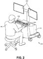
- FIG. 2 illustrates a command console 200 for a surgical robotic system 100 according to one embodiment.
- the command console 200 includes a console base 201, display modules 202, e.g., monitors, and control modules, e.g., a keyboard 203 and joystick 204.
- one or more of the command module 200 functionality may be integrated into a base 101 of the surgical robotic system 100 or another system communicatively coupled to the surgical robotic system 100.
- a user 205 e.g., a physician, remotely controls the surgical robotic system 100 from an ergonomic position using the command console 200.
- the console base 201 may include a central processing unit, a memory unit, a data bus, and associated data communication ports that are responsible for interpreting and processing signals such as camera imagery and tracking sensor data, e.g., from the endoscope 118 shown in FIG. 1 . In some embodiments, both the console base 201 and the base 101 perform signal processing for load-balancing.
- the console base 201 may also process commands and instructions provided by the user 205 through the control modules 203 and 204.
- the control modules may include other devices, for example, computer mice, track pads, trackballs, control pads, video game controllers, and sensors (e.g., motion sensors or cameras) that capture hand gestures and finger gestures.
- the user 205 can control a surgical instrument such as the endoscope 118 using the command console 200 in a velocity mode or position control mode.
- velocity mode the user 205 directly controls pitch and yaw motion of a distal end of the endoscope 118 based on direct manual control using the control modules.
- movement on the joystick 204 may be mapped to yaw and pitch movement in the distal end of the endoscope 118.
- the joystick 204 can provide haptic feedback to the user 205.
- the joystick 204 vibrates to indicate that the endoscope 118 cannot further translate or rotate in a certain direction.
- the command console 200 can also provide visual feedback (e.g., pop-up messages) and/or audio feedback (e.g., beeping) to indicate that the endoscope 118 has reached maximum translation or rotation.
- the command console 200 uses a three-dimensional (3D) map of a patient and pre-determined computer models of the patient to control a surgical instrument, e.g., the endoscope 118.
- the command console 200 provides control signals to robotic arms 102 of the surgical robotic system 100 to manipulate the endoscope 118 to a target location. Due to the reliance on the 3D map, position control mode requires accurate mapping of the anatomy of the patient.
- users 205 can manually manipulate robotic arms 102 of the surgical robotic system 100 without using the command console 200.
- the users 205 may move the robotic arms 102, endoscopes 118, and other surgical equipment to access a patient.
- the surgical robotic system 100 may rely on force feedback and inertia control from the users 205 to determine appropriate configuration of the robotic arms 102 and equipment.
- the display modules 202 may include electronic monitors, virtual reality viewing devices, e.g., goggles or glasses, and/or other means of display devices.
- the display modules 202 are integrated with the control modules, for example, as a tablet device with a touchscreen.
- the user 205 can both view data and input commands to the surgical robotic system 100 using the integrated display modules 202 and control modules.
- the display modules 202 can display 3D images using a stereoscopic device, e.g., a visor or goggle.
- the 3D images provide an "endo view” (i.e., endoscopic view), which is a computer 3D model illustrating the anatomy of a patient.
- the "endo view” provides a virtual environment of the patient's interior and an expected location of an endoscope 118 inside the patient.
- a user 205 compares the "endo view” model to actual images captured by a camera to help mentally orient and confirm that the endoscope 118 is in the correct-or approximately correct-location within the patient.
- the "endo view” provides information about anatomical structures, e.g., the shape of an intestine or colon of the patient, around the distal end of the endoscope 118.
- the display modules 202 can simultaneously display the 3D model and computerized tomography (CT) scans of the anatomy the around distal end of the endoscope 118. Further, the display modules 202 may overlay pre-determined optimal navigation paths of the endoscope 118 on the 3D model and CT scans.
- CT computerized tomography
- a model of the endoscope 118 is displayed with the 3D models to help indicate a status of a surgical procedure.
- the CT scans identify a lesion in the anatomy where a biopsy may be necessary.
- the display modules 202 may show a reference image captured by the endoscope 118 corresponding to the current location of the endoscope 118.
- the display modules 202 may automatically display different views of the model of the endoscope 118 depending on user settings and a particular surgical procedure.
- the display modules 202 show an overhead fluoroscopic view of the endoscope 118 during a navigation step as the endoscope 118 approaches an operative region of a patient.
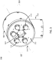
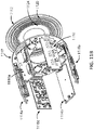
- FIG. 3 illustrates a perspective view of an instrument device manipulator (IDM) 300 for a surgical robotic system
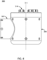
- FIG. 4 is a side view of the IDM 300, according to one embodiment.
- the IDM 300 is configured to attach a surgical tool to a robotic surgical arm in a manner that allows the surgical tool to be continuously rotated or "rolled" about an axis of the surgical tool.
- the IDM 300 includes a base 302 and a surgical tool holder assembly 304.
- the surgical tool holder assembly 304 further includes an outer housing 306, a surgical tool holder 308, an attachment interface 310, a passage 312, and a plurality of torque couplers 314.
- the IDM 300 may be used with a variety of surgical tools (not shown in FIG. 3 ), which may include a housing and an elongated body, and which may be for a laparoscope, an endoscope, or other types of end-effectors of surgical instruments.
- the base 302 removeably or fixedly mounts the IDM 300 to a surgical robotic arm of a surgical robotic system.
- the base 302 is fixedly attached to the outer housing 306 of the surgical tool holder assembly 304.
- the base 302 may be structured to include a platform which is adapted to rotatably receive the surgical tool holder 308 on the face opposite from the attachment interface 310.
- the platform may include a passage aligned with the passage 312 to receive the elongated body of the surgical tool and, in some embodiments, an additional elongated body of a second surgical tool mounted coaxially with the first surgical tool.
- the surgical tool holder assembly 304 is configured to secure a surgical tool to the IDM 300 and rotate the surgical tool relative to the base 302.
- Mechanical and electrical connections are provided from the surgical arm to the base 302 and then to the surgical tool holder assembly 304 to rotate the surgical tool holder 308 relative to the outer housing 306 and to manipulate and/or deliver power and/or signals from the surgical arm to the surgical tool holder 308 and ultimately to the surgical tool.
- Signals may include signals for pneumatic pressure, electrical power, electrical signals, and/or optical signals.
- the outer housing 306 provides support for the surgical tool holder assembly 304 with respect to the base 302.
- the outer housing 306 is fixedly attached to the base 302 such that it remains stationary relative to the base 302, while allowing the surgical tool holder 308 to rotate freely relative to the outer housing 306.
- the outer housing 306 is cylindrical in shape and fully circumscribes the surgical tool holder 308.
- the outer housing 306 may be composed of rigid materials (e.g., metals or hard plastics). In alternate embodiments, the shape of the housing may vary.
- the surgical tool holder 308 secures a surgical tool to the IDM 300 via the attachment interface 310.
- the surgical tool holder 308 is capable of rotating independent of the outer housing 306.
- the surgical tool holder 308 rotates about a rotational axis 316, which co-axially aligns with the elongated body of a surgical tool such that the surgical tool rotates with the surgical tool holder 308.
- the attachment interface 310 is a face of the surgical tool holder 308 that attaches to the surgical tool.
- the attachment interface 310 includes a first portion of an attachment mechanism that reciprocally mates with a second portion of the attachment mechanism located on the surgical tool, which will be discussed in greater detail with regards to FIGS. 8A and 8B .
- the attachment interface 310 comprises a plurality of torque couplers 314 that protrude outwards from the attachment interface 310 and engage with respective instrument inputs on the surgical tool.
- a surgical drape coupled to a sterile adapter, may be used to create a sterile boundary between the IDM 300 and the surgical tool.
- the sterile adapter may be positioned between the attachment interface 310 and the surgical tool when the surgical tool is secured to the IDM 300 such that the surgical drape separates the surgical tool and the patient from the IDM 300 and the surgical robotics system.
- the passage 312 is configured to receive the elongated body of a surgical tool when the surgical tool is secured to the attachment interface 310.
- the passage 312 is co-axially aligned with the longitudinal axis of the elongated body of the surgical tool and the rotational axis 316 of the surgical tool holder 308.
- the passage 312 allows the elongated body of the surgical tool to freely rotate within the passage 312. This configuration allows the surgical tool to be continuously rotated or rolled about the rotational axis 316 in either direction with minimal or no restrictions.
- the plurality of torque couplers 314 are configured to engage and drive the components of the surgical tool when the surgical tool is secured to the surgical tool holder 308.
- Each torque coupler 314 is inserted into a respective instrument input located on the surgical tool.
- the plurality of torque couplers 314 may also serve to maintain rotational alignment between the surgical tool and the surgical tool holder 308.
- each torque coupler 314 is shaped as a cylindrical protrusion that protrudes outwards from the attachment interface 310.
- Notches 318 may be arranged along the outer surface area of the cylindrical protrusion. In some embodiments, the arrangement of the notches 318 creates a spline interface.
- the instrument inputs on the surgical tool are configured to have a complementary geometry to the torque couplers 314.
- the instrument inputs of the surgical tool may be cylindrical in shape and have a plurality of ridges that reciprocally mate with the plurality of notches 318 on each torque coupler 314 and thus impart a torque on the notches 318.
- the top face of the cylindrical protrusion may include the plurality of notches 318 configured to mate with a plurality of ridges in respective instrument inputs. In this configuration, each torque coupler 314 fully engages with its respective instrument input.
- each torque coupler 314 may be coupled to a spring that allows the torque coupler to translate.
- the spring causes each torque coupler 314 to be biased to spring outwards away from the attachment interface 310.
- the spring is configured to create translation in an axial direction, i.e., protract away from the attachment interface 310 and retract towards the surgical tool holder 308.
- each torque coupler 314 is capable of partially retracting into the surgical tool holder 308.
- each torque coupler 314 is capable of fully retracting into the surgical tool holder 308 such that the effective height of each torque coupler is zero relative to the attachment interface 310.
- FIG. 3 the spring causes each torque coupler 314 to be biased to spring outwards away from the attachment interface 310.
- the spring is configured to create translation in an axial direction, i.e., protract away from the attachment interface 310 and retract towards the surgical tool holder 308.
- each torque coupler 314 is capable of partially retracting into the surgical tool holder 308.
- each torque coupler 314 may be coupled to a single spring, a plurality of springs, or a respective spring for each torque coupler.
- each torque coupler 314 is driven by a respective actuator that causes the torque coupler to rotate in either direction.
- each torque coupler 314 is capable of transmitting power to tighten or loosen pull-wires within a surgical tool, thereby manipulating a surgical tool's end-effectors.
- the IDM 300 includes five torque couplers 314, but the number may vary in other embodiments depending on the desired number of degrees of freedom for a surgical tool's end-effectors.
- a surgical drape coupled to a sterile adapter, may be used to create a sterile boundary between the IDM 300 and the surgical tool.
- the sterile adapter may be positioned between the attachment interface 310 and the surgical tool when the surgical tool is secured to the IDM 300, and the sterile adapter may be configured to transmit power from each torque coupler 314 to the respective instrument input.
- the embodiment of the IDM 300 illustrated in FIG. 3 may be used in various configurations with a surgical robotic system.
- the desired configuration may depend on the type of surgical procedure being performed on a patient or the type of surgical tool being used during the surgical procedure.
- the desired configuration of the IDM 300 may be different for an endoscopic procedure than for a laparoscopic procedure.
- the IDM 300 may be removeably or fixedly attached to a surgical arm such that the attachment interface 310 is proximal to a patient during the surgical procedure.
- the surgical tool is secured to the IDM 300 on a side proximal to the patient.
- a surgical tool for use with the front-mount configuration is structured such that the elongated body of the surgical tool extends from a side that is opposite of the attachment interface of the surgical tool. As a surgical tool is removed from the IDM 300 in a front-mount configuration, the surgical tool will be removed in a proximal direction to the patient.
- the IDM 300 may be removeably or fixedly attached to a surgical arm such that the attachment interface 310 is distal to a patient during the surgical procedure.
- the surgical tool is secured to the IDM 300 on a side distal to the patient.
- a surgical tool for use with the back-mount configuration is structured such that the elongated body of the surgical tool extends from the attachment interface of the surgical tool. This configuration increases patient safety during tool removal from the IDM 300. As a surgical tool is removed from the IDM 300 in a back-mount configuration, the surgical tool will be removed in a distal direction from the patient.
- Certain configurations of a surgical tool may be structured such that the surgical tool can be used with an IDM in either a front-mount configuration or a back-mount configuration.
- the surgical tool includes an attachment interface on both ends of the surgical tool.
- the physician may decide the configuration of the IDM depending on the type of surgical procedure being performed.
- the back-mount configuration may be beneficial for laparoscopic procedures wherein laparoscopic tools may be especially long relative to other surgical instruments.
- the back-mount configuration decreases the effective tool length of the surgical tool by receiving a portion of the elongated body through the passage 312 and thereby decreases the arc of motion required by the surgical arm to position the surgical tool.
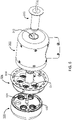
- FIGS. 5-6 illustrate perspective exploded views of an example surgical tool 500 secured to the instrument device manipulator 300 of FIG. 3 , according to one embodiment.
- the surgical tool 500 includes a housing 502, an elongated body 504, and a plurality of instrument inputs 600.
- the elongated body 504 may be a laparoscope, an endoscope, or other surgical instrument having end-effectors.
- the plurality of torque couplers 314 protrude outwards from the attachment interface 310 to engage with the instrument inputs 600 of the surgical tool.
- the structure of the instrument inputs 600 can be seen in FIG. 6 , wherein the instrument inputs 600 have corresponding geometry to the torque couplers 314 to ensure secure surgical tool engagement.
- a surgical drape may be used to maintain a sterile boundary between the IDM 300 and an outside environment (i.e., an operating room).
- the surgical drape comprises a sterile adapter 506, a first protrusion 508, and a second protrusion 510.
- a sterile sheet is connected to the sterile adapter and the second protrusion and drapes around the IDM 300 to create the sterile boundary.
- the sterile adapter 506 is configured to create a sterile interface between the IDM 300 and the surgical tool 500 when secured to the IDM 300.
- the sterile adapter 506 has a disk-like geometry that covers the attachment interface 310 of the IDM 300.
- the sterile adapter 506 comprises a central hole 508 that is configured to receive the elongated body 504 of the surgical tool 500.
- the sterile adapter 506 is positioned between the attachment interface 310 and the surgical tool 500 when the surgical tool 500 is secured to the IDM 300, creating the sterile boundary between the surgical tool 500 and the IDM 300 and allowing the elongated body 504 to pass through the passage 312.
- the sterile adapter 506 may be capable of rotating with the surgical tool holder 308, transmitting the rotational torque from the plurality of torque couplers 314 to the surgical tool 500, passing electrical signals between the IDM 300 and the surgical tool 500, or some combination thereof.
- the sterile adapter 506 further comprises a plurality of couplers 512.
- a first side of a coupler 512 is configured to engage with a respective torque coupler 314 while a second side of a coupler 512 is configured to engage with a respective instrument input 600.
- each coupler 512 is structured as a cylindrical protrusion including a plurality of notches.
- Each side of the coupler 512 has complementary geometry to fully engage with the respective torque coupler 314 and the respective instrument input 600.
- Each coupler 512 is configured to rotate in a clockwise or counter-clockwise direction with the respective torque coupler 314. This configuration allows each coupler 512 to transfer rotational torque from the plurality of torque couplers 314 of the IDM 300 to the plurality of instrument inputs 600 of the surgical tool 500, and thus control the end-effectors of the surgical tool 500.
- the first protrusion 508 and the second protrusion 510 are configured to pass through the passage 312 of the IDM 300 and mate with each other inside the passage 312.
- Each protrusion 508, 510 is structured to allow the elongated body 504 to pass through the protrusion and thus the passage 312.
- the connection of the first protrusion 508 and the second protrusion 510 creates the sterile boundary between the IDM 300 and the outside environment (i.e., an operating room).
- the surgical drape is discussed in further detail with regards to FIGS. 13-16 .
- FIG. 7 illustrates a zoomed-in, perspective view of an actuation mechanism for engagement and disengagement of a surgical tool 500 from a sterile adapter 506 of a surgical drape, according to one embodiment.
- the axis of surgical tool insertion into the patient during a surgical procedure is the same as the axis of surgical tool removal.
- the surgical tool 500 can be de-articulated from the sterile adapter 506 and the IDM 300 before removing the surgical tool 500.
- FIG. 1 illustrates a zoomed-in, perspective view of an actuation mechanism for engagement and disengagement of a surgical tool 500 from a sterile adapter 506 of a surgical drape, according to one embodiment.
- the plurality of couplers 512 are configured to translate in an axial direction, i.e., protract away from and retract towards the sterile adapter 506.
- the translation of the plurality of couplers 512 is actuated by the actuation mechanism which ensures de-articulation of the surgical tool 500 by disengaging the plurality of couplers 512 from the respective instrument inputs 600.
- the actuation mechanism includes a wedge 702 and a pusher plate 704.
- the wedge 702 is a structural component that activates the pusher plate 704 during the process of surgical tool disengagement.
- the wedge 702 is located within the housing 502 of the surgical tool 500 along the outer perimeter of the housing 502.
- the wedge 702 is oriented such that contact with the pusher plate 704 causes the pusher plate 704 to depress into the sterile adapter 506 if the housing 502 of the surgical tool 500 is rotated clockwise relative to the sterile adapter 506.
- the wedge 702 may be configured such that the housing 502 of the surgical tool 500 is rotated counter-clockwise rather than clockwise.
- Geometries other than a wedge may be employed, such as an arch-shaped ramp, given that the structure is able to depress the pusher plate when rotating.
- the pusher plate 704 is an actuator that disengages the plurality of couplers 512 from the surgical tool 500. Similar to the plurality of torque couplers 314, each of the couplers 512 may be coupled to one or more springs that bias each coupler 512 to spring outwards away from the sterile adapter 506. The plurality of couplers 512 are further configured to translate in an axial direction, i.e., protract away from and retract into the sterile adapter 506. The pusher plate 704 actuates the translational movement of the couplers 512.
- the pusher plate 704 causes the spring or plurality of springs coupled to each coupler 512 to compress, resulting in the couplers 512 retracting into the sterile adapter 506.
- the pusher plate 704 is configured to cause simultaneous retraction of the plurality of couplers 512. Alternate embodiments may retract the couplers 512 in a specific sequence or a random order.
- the pusher plate 704 causes the plurality of couplers 512 to partially retract into the sterile adapter 506. This configuration allows a surgical tool 500 to be de-articulated from the sterile adapter 506 before the surgical tool 500 is removed.
- This configuration also allows a user to de-articulate the surgical tool 500 from the sterile adapter 506 at any desired time without removing the surgical tool 500.
- Alternate embodiments may fully retract the plurality of couplers 512 into the sterile adapter 506 such that the effective height of each coupler 512 measured is zero.
- the pusher plate 704 may cause the plurality of torque couplers 314 to retract synchronously with the plurality of respective couplers 512.
- FIGS. 8A and 8B illustrate a process of engaging and disengaging a surgical tool from a sterile adapter, according to one embodiment.
- FIG. 8A illustrates a sterile adapter 506 and a surgical tool 500 in a secured position, such that the two components are secured together and the plurality of couplers 512 are fully engaged with respective instrument inputs 600 of the surgical tool 500. To achieve the secured position as illustrated in FIG.
- the elongated body 504 (not shown) of the surgical tool 500 is passed through the central hole 508 (not shown) of the sterile adapter 506 until mating surfaces of the surgical tool 500 and the sterile adapter 506 are in contact, and the surgical tool 500 and the sterile adapter 506 are secured to each other by a latching mechanism.
- the latching mechanism comprises a ledge 802 and a latch 804.
- the ledge 802 is a structural component that secures the latch 804 in the secured position.
- the ledge 802 is located within the housing 502 of the surgical tool 500 along the outer perimeter of the housing 502.
- the ledge 802 is oriented such that it rests below a protrusion on the latch 804, preventing the latch 804 and thereby the sterile adapter 506 from pulling away from the surgical tool 500 due to the sprung-up nature of the plurality of couplers 512, as described with regards to FIG. 7 .
- the latch 804 is a structural component that mates with the ledge 802 in the secured position.
- the latch 804 protrudes from the mating surface of the sterile adapter 506.
- the latch 804 comprises a protrusion that is configured to rest against the ledge 802 when the surgical tool 500 is secured to sterile adapter 506.
- the housing 502 of the surgical tool 500 is capable of rotating independent of the rest of the surgical tool 500. This configuration allows the housing 502 to rotate relative to the sterile adapter 506 such that the ledge 802 is secured against the latch 804, thereby securing the surgical tool 500 to the sterile adapter 502.
- FIG. 8A the housing 502 of the surgical tool 500 is capable of rotating independent of the rest of the surgical tool 500. This configuration allows the housing 502 to rotate relative to the sterile adapter 506 such that the ledge 802 is secured against the latch 804, thereby securing the surgical tool 500 to the sterile adapter 502.
- the housing 502 is rotated counter-clockwise to achieve the secured position, but other embodiments may be configured for clockwise rotation.
- the ledge 802 and the latch 804 may have various geometries that lock the sterile adapter 506 and the surgical tool 500 in the secured position.
- FIG. 8B illustrates the sterile adapter 506 and the surgical tool 500 in an unsecured position, in which the surgical tool 500 may be removed from the sterile adapter 506.
- the housing 502 of the surgical tool 500 is capable of rotating independent of the rest of the surgical tool 500. This configuration allows the housing 502 to rotate even while the plurality of couplers 512 are engaged with the instrument inputs 600 of the surgical tool 500.
- a user rotates the housing 502 of the surgical tool 500 clockwise relative to the sterile adapter 506.
- the wedge 702 contacts the pusher plate 704 and progressively depresses the pusher plate 704 as it slides against the angled plane of the wedge 702, thereby causing the plurality of couplers 512 to retract into the sterile adapter 506 and disengage from the plurality of instrument inputs 600.
- Further rotation causes the latch 804 to contact an axial cam 806, which is structured similar to wedge 702.
- the axial cam 806 causes the latch 804 to flex outwards away from the surgical tool 500 such that the latch 804 is displaced from the ledge 802.
- the axial cam 806 may have various geometries such that rotation causes the latch 804 to flex outwards.
- the direction of rotation of the housing 502 of the surgical tool 500 may be configured as counter-clockwise rotation to unsecure the latch 804 from the ledge 802.
- alternate embodiments may include similar components but the location of the components may be switched between the sterile adapter 506 and the surgical tool 500.
- the ledge 802 may be located on the sterile adapter 506 while the latch 804 may be located on the surgical tool 500.
- an outer portion of the sterile adapter 506 may be rotatable relative to the plurality of couplers 512 rather than the housing 502 of the surgical tool 500.
- Alternate embodiments may also include a feature to lock the rotation of the housing 502 of the surgical tool 502 when the housing 502 is fully rotated relative to the instrument inputs 600. This configuration prevents rotation of the surgical tool if the instrument inputs 600 have been de-articulated from the couplers 512.
- the retraction and protraction of the couplers 512 may be coupled with a respective retraction and protraction of the torque couplers 314, such that a coupler 512 engaged with a torque coupler 314 will translate together.
- FIGS. 9A and 9B illustrate a process of surgical tool engagement and disengagement of a surgical tool from a sterile adapter, according to another embodiment.
- a sterile adapter 900 may include an outer band 902 that secures the surgical tool 904 to the sterile adapter 900.
- the surgical tool 902 comprises a ramp 906 on the outer surface of the housing 908.
- the ramp 906 includes a notch 910 that is configured to receive a circular protrusion 912, which is positioned on an inner surface of the outer band 902 of the sterile adapter 900.
- the outer band 902 is capable of rotating independent of and relative to the sterile adapter 900 and the surgical tool 904. As the outer band 902 rotates in a first direction, the circular protrusion 912 glides up the surface of the ramp 906 until the circular protrusion 912 is nested within the notch 910, thereby securing the sterile adapter 900 and the surgical tool 904 together. Rotation of the outer band 902 in a second direction causes the sterile adapter 900 and the surgical tool 904 to unsecure from each other. In certain embodiments, this mechanism may be coupled with a de-articulation of the plurality of couplers 914 on the sterile adapter 900, as described with regards to FIGS. 7-8 .
- Alternate embodiments of surgical tool disengagement may include additional features, such as an impedance mode.
- an impedance mode the surgical robotics system may control whether the surgical tool can be removed from the sterile adapter by a user. The user may initiate the disengagement mechanism by rotating the outer housing of the surgical tool and unsecuring the surgical tool from the sterile adapter, but the surgical robotics system may not release the couplers from the instrument inputs. Only once the surgical robotics system has transitioned into the impedance mode are the couplers released and the user can remove the surgical tool.
- An advantage of keeping the surgical tool engaged is that the surgical robotics system can control the end-effectors of the surgical tool and position them for tool removal before the surgical tool is removed to minimize damage to the surgical tool.
- the pusher plate 704 may have a hard-stop such that the pusher plate can be depressed up to a certain distance.
- the hard-stop of the pusher plate may be adjustable such that the hard-stop coincides with the maximum amount of rotation of the housing of the surgical tool. Thus, once the full rotation is reached, the hard-stop is also met by the pusher plate.
- a plurality of sensors may detect these events and trigger the impedance mode.
- the hard-stop of the pusher plate may have compliance, such that the hard-stop may yield in an emergency situation.
- the hard-stop of the pusher plate may be coupled to a spring, allowing the hard-stop to yield in response to additional force.
- the hard-stop of the pusher plate may be rigid such that emergency tool removal occurs by removing the latch that secures the surgical tool to the sterile adapter.
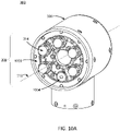
- FIG. 10A illustrates a perspective view of a mechanism for rolling a surgical tool holder 308 within an instrument device manipulator 300, according to one embodiment.
- the attachment interface 310 is removed to expose the roll mechanism.
- This mechanism allows the surgical tool holder 308 to continuously rotate or "roll" about the rotational axis 316 in either direction.
- the roll mechanism comprises a stator gear 1002 and a rotor gear 1004.
- the stator gear 1002 is a stationary gear configured to mate with the rotor gear 1004.
- the stator gear 1002 is a ring-shaped gear comprising gear teeth along the inner circumference of the ring.
- the stator gear 1002 is fixedly attached to the outer housing 306 behind the attachment interface 310.
- the stator gear 1002 has the same pitch as the rotor gear 1004, such that the gear teeth of the stator gear 1002 are configured to mate with the gear teeth of the rotor gear 1004.
- the stator gear 1002 may be composed of rigid materials (e.g., metals or hard plastics).
- the rotor gear 1004 is a rotating gear configured to induce rotation of the surgical tool holder 308. As illustrated in FIG. 10A , the rotor gear 1004 is a circular gear comprising gear teeth along its outer circumference. The rotor gear 1004 is positioned behind the attachment interface 310 and within the inner circumference of the stator gear 1002 such that the gear teeth of the rotor gear 1004 mate with the gear teeth of the stator gear. As previously described, the rotor gear 1004 and the stator gear 1002 have the same pitch. In the embodiment of FIG. 10A , the rotor gear 1004 is coupled to a drive mechanism (e.g., a motor) that causes the rotor gear 1004 to rotate in a clockwise or counter-clockwise direction.
- a drive mechanism e.g., a motor
- the drive mechanism may receive signals from an integrated controller within the surgical tool holder assembly 304. As the drive mechanism causes the rotor gear 1004 to rotate, the rotor gear 1004 travels along the gear teeth of the stator gear 1002, thereby causing the surgical tool holder 308 to rotate. In this configuration, the rotor gear 1004 is capable of continuously rotating in either direction and thus allows the surgical tool holder 308 to achieve infinite roll about the rotational axis 316. Alternate embodiments may use similar mechanisms to allow for infinite roll, such as a configuration of a ring gear and a pinion gear.
- FIG. 10B illustrates a cross-sectional view of an instrument device manipulator 300, according to one embodiment.
- the roll mechanism is coupled with a plurality of bearing 1006.
- a bearing is a mechanical component that reduces friction between moving parts and facilitates rotation around a fixed axis.
- One bearing alone is capable of supporting the radial or torsional loading as the surgical tool holder 308 rotates within the outer housing 306.
- the IDM 300 includes two bearings 1006a, 1006b fixedly attached to the surgical tool holder 308 such that a plurality of components (such as balls or cylinders) within the bearings 1006 contacts the outer housing 306.
- a first bearing 1006a is secured at a first end behind the attachment interface 310 and a second bearing 1006b is secured at a second end.
- This configuration improves rigidity and support between the first end and the second end of the surgical tool holder 308 as the surgical tool holder 308 rotates within the outer housing 306.
- Alternate embodiments may include additional bearings that provide additional support along the length of the surgical tool holder.
- FIG. 10B also illustrates sealing components within the IDM 300, according to one embodiment.
- the IDM 300 comprises a plurality of O-rings 1008 and a plurality of gaskets 1010 which are configured to seal a junction between two surfaces to prevent fluids from entering the junction.
- the IDM includes O-rings 1008a, 1008b, 1008c, 1008d, 1008e between junctions of the outer housing and gaskets 1010a, 1010b between junctions within the surgical tool holder 308. This configuration helps to maintain sterility of the components within the IDM 300 during a surgical procedure.
- Gaskets and O-rings are typically composed of strong elastomeric materials (e.g., rubber).
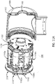
- FIG. 11A illustrates a partially exploded, perspective view of the internal components of an instrument device manipulator and certain electrical components thereof, according to one embodiment.
- the internal components of the surgical tool holder 308 include a plurality of actuators 1102, a motor, a gearhead (not shown), a torque sensor (not shown), a torque sensor amplifier 1110, a slip ring 1112, a plurality of encoder boards 1114, a plurality of motor power boards 1116, and an integrated controller 1118.
- the plurality of actuators 1102 drive the rotation of each of the plurality of torque couplers 314.
- an actuator such as 1102a or 1102b, is coupled to a torque coupler 314 via a motor shaft.
- the motor shaft may be a keyed shaft such that it includes a plurality of grooves to allow the motor shaft to securely mate to a torque coupler 314.
- the actuator 1102 causes the motor shaft to rotate in a clockwise or counter-clockwise direction, thereby causing the respective torque coupler 314 to rotate in that direction.
- the motor shaft may be torsionally rigid but spring compliant, allowing the motor shaft and thus the torque coupler 314 to rotate and to translate in an axial direction.
- Each actuator 1102 may receive electrical signals from the integrated controller 1118 indicating the direction and amount to rotate the motor shaft.
- the surgical tool holder 308 includes five torque couplers 314 and thus five actuators 1102.
- the motor drives the rotation of the surgical tool holder 308 within the outer housing 306.
- the motor may be structurally equivalent to one of the actuators, except that it is coupled to the rotor gear 1004 and stator gear 1002 (see FIG. 10A ) for rotating the surgical tool holder 308 relative to the outer housing 306.
- the motor causes the rotor gear 1004 to rotate in a clockwise or counter-clockwise direction, thereby causing the rotor gear 1004 to travel about the gear teeth of the stator gear 1002.
- This configuration allows the surgical tool holder 308 to continuously roll or rotate without being hindered by potential wind-up of cables or pull-wires.
- the motor may receive electrical signals from the integrated controller 1118 indicating the direction and amount to rotate the motor shaft.
- the gearhead controls the amount of torque delivered to the surgical tool 500.
- the gearhead may increase the amount of torque delivered to the instrument inputs 600 of the surgical tool 500.
- Alternate embodiments may be configured such that the gearhead decreases the amount of torque delivered to the instrument inputs 600.
- the torque sensor measures the amount of torque produced on the rotating surgical tool holder 308.
- the torque sensor is capable of measuring torque in the clockwise and the counter-clockwise direction.
- the torque measurements may be used to maintain a specific amount of tension in a plurality of pull-wires of a surgical tool.
- some embodiments of the surgical robotics system may have an auto-tensioning feature, wherein, upon powering on the surgical robotics system or engaging a surgical tool with an IDM, the tension on the pull-wires of the surgical tool will be pre-loaded.
- the amount of tension on each pull-wire may reach a threshold amount such that the pull-wires are tensioned just enough to be taut.
- the torque sensor amplifier 1110 comprises circuitry for amplifying the signal that measures the amount of torque produced on the rotating surgical tool holder 308.
- the torque sensor is mounted to the motor.
- the slip ring 1112 enables the transfer of electrical power and signals from a stationary structure to a rotating structure.
- the slip ring 1112 is structured as a ring including a central hole that is configured to align with the passage 312 of the surgical tool holder 308, as is also shown in an additional perspective view of the slip ring 1112 in FIG. 11B .
- a first side of the slip ring 1112 includes a plurality of concentric grooves 1120 while a second side of the slip ring 1112 includes a plurality of electrical components for the electrical connections provided from the surgical arm and the base 302, as described with regards to FIG. 3 .
- the slip ring 1112 is secured to the outer housing 306 of the surgical tool holder 308 at a specific distance from the outer housing 306 to allocate space for these electrical connections.
- the plurality of concentric grooves 1120 are configured to mate with a plurality of brushes 1122 attached to the integrated controller. The contact between the grooves 1120 and the brushes 1122 enables the transfer of electrical power and signals from the surgical arm and base to the surgical tool holder.
- the plurality of encoder boards 1114 read and process the signals received through the slip ring from the surgical robotic system.
- Signals received from the surgical robotic system may include signals indicating the amount and direction of rotation of the surgical tool, signals indicating the amount and direction of rotation of the surgical tool's end-effectors and/or wrist, signals operating a light source on the surgical tool, signals operating a video or imaging device on the surgical tool, and other signals operating various functionalities of the surgical tool.
- the configuration of the encoder boards 1114 allows the entire signal processing to be performed completely in the surgical tool holder 308.
- the plurality of motor power boards 1116 each comprises circuitry for providing power to the motors.
- the integrated controller 1118 is the computing device within the surgical tool holder 308.
- the integrated controller 1118 is structured as a ring including a central hole that is configured to align with the passage 312 of the surgical tool holder 308.
- the integrated controller 1118 includes a plurality of brushes 1122 on a first side of the integrated controller 1118. The brushes 1122 contact the slip ring 1112 and receive signals that are delivered from the surgical robotics system through the surgical arm, the base 302, and finally through the slip ring 1112 to the integrated controller 1118.
- the integrated controller 1118 is configured to send various signals to respective components within the surgical tool holder 308.
- the functions of the encoder boards 1114 and the integrated controller 1118 may be distributed in a different manner than is described here, such that the encoder boards 1114 and the integrated controller 1118 may perform the same functions or some combination thereof.
- FIG. 11B illustrates a partially exploded, perspective view of the internal components of an instrument device manipulator and certain electrical components thereof, according to one embodiment.
- the embodiment of FIG. 11B includes two encoder boards 1114a and 1114b, a torque sensor amplifier 1110, and three motor power boards 1116a, 1116b, and 1116c. These components are secured to the integrated controller 1118 and protrude outwards, extending perpendicularly from the integrated controller 1118. This configuration provides room for the plurality of actuators 1102 and motor to be positioned within the electrical boards.
- the slip ring 1112 is secured at a specific distance from the outer housing 306.
- the slip ring 1112 is supported by a plurality of alignment pins, a plurality of coil springs, and a shim.
- the slip ring 1112 includes a hole 1124 on each side of the center hole of the slip ring 1112 that is configured to accept a first side of an alignment pin while a second side of the alignment pin is inserted into a respective hole in the outer housing 306.
- the alignment pins may be composed of rigid materials (e.g., metal or hard plastics).
- the plurality of coil springs are secured around the center of the slip ring 1112 and configured to bridge the space and maintain contact between the slip ring 1112 and the outer housing 306.
- the coil springs may beneficially absorb any impact to the IDM 300.
- the shim is ring-shaped spacer that is positioned around the center hole of the slip ring 1112 to add further support between the slip ring 1112 and the outer housing 306.
- these components provide stability to the slip ring 1112 as the plurality of brushes 1122 on the integrated controller 1118 contact and rotate against the plurality of concentric grooves 1120.
- the number of alignment pins, coil springs, and shims may vary until the desired support between the slip ring 1112 and the outer housing 306 is achieved.
- FIG. 12 illustrates a zoomed-in, perspective view of electrical components of an instrument device manipulator 300 for roll indexing the surgical tool holder 308, according to one embodiment.
- Roll indexing monitors the position of the surgical tool holder 308 relative to the outer housing 306 such that the position and orientation of the surgical tool 500 is continuously known by the surgical robotics system.
- the embodiment of FIG. 12 includes a micro switch 1202 and a boss 1204.
- the micro switch 1202 and the boss 1204 are secured within the surgical tool holder 308.
- the boss 1204 is a structure on the outer housing 306 that is configured to contact the micro switch 1202 as the surgical tool holder 308 rotates, thus activating the micro switch each time there is contact with the boss 1204.
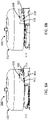
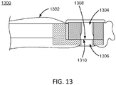
- FIG. 13 illustrates a cross-sectional view of a surgical drape for an instrument device manipulator for a surgical robotics system, according to one embodiment.
- the surgical drape 1300 provides a sterile boundary for the IDM, the surgical arm, and other portions of the surgical robotics system during a surgical procedure.
- the surgical drape 1300 is configured for use with an IDM that includes a passage configured to receive an elongated body of a surgical tool when the surgical tool is attached to the IDM, such as IDM 300.
- the surgical drape 1300 comprises a sterile sheet 1302, a first protrusion 1304, and a second protrusion 1306.
- the sterile sheet 1302 creates and maintains a sterile environment for portions of the surgical robotics system during a surgical procedure.
- the sterile sheet 1302 is configured to cover the IDM 300, the surgical arm, and portions of the surgical robotics system.
- the sterile sheet 1302 may be composed of a variety of materials, such as plastics (e.g., polypropylene), paper, and other materials that may be resistant to fluids.
- the first protrusion 1304 is a cylindrical tube configured to receive an elongated body of a surgical tool, such as elongated body 504 of surgical tool 500.
- the first protrusion 1304 is connected to a first portion of the sterile sheet 1302, and a first end of the first protrusion 1304 is configured to be inserted into a first end of the passage 312.
- the first end of the first protrusion 1304 includes a mating interface 1308 that is configured to mate with a reciprocal mating interface 1310 on the second protrusion 1306.
- the first protrusion 1304 may be composed of rigid materials (e.g., metals or hard plastics).
- the second protrusion 1306 is a cylindrical tube configured to receive an elongated body of a surgical tool, such as elongated body 504 of surgical tool 500.
- the second protrusion 1306 is connected to a second portion of the sterile sheet 1302, and a first end of the second protrusion 1306 is configured to be inserted into a second end of the passage 312, such that the first protrusion 1304 and the second protrusion 1306 are inserted into opposite ends of the passage 312.
- the first end of the second protrusion 1306 includes a reciprocal mating interface 1310 that is configured to removeably couple with the mating interface 1308 on the first protrusion 1304 inside the passage 312.
- the second protrusion 1306 may be composed of rigid materials (e.g., metals or hard plastics).
- coupling mechanisms may include hook-and-loop fasteners, friction-fit tubes, threaded tubes, and other suitable coupling mechanisms.
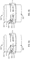
- FIG. 14 illustrates a cross-sectional view of reciprocal mating interfaces of a surgical drape for a surgical tool holder, according to one embodiment.
- the first end of the first protrusion 1304 includes a mating interface 1308.
- the mating interface 1308 is structured as two concentric tubes with a crevice between the concentric tubes, as shown by the cross-section in FIG. 14 , wherein the crevice is a ring configured to receive an end of another tube.
- the reciprocal mating interface 1310 at the first end of the second protrusion 1306 is structured as a tube that tapers such that the diameter at the first end of the tube is smaller relative to the rest of the tube.
- the tapered end facilitates easy insertion of the reciprocal mating interface 1310 into the mating interface 1308.
- the inner surfaces of the first protrusion 1304 and the second protrusion 1306 to contact an unsterile surface while the outer surfaces are able to remain sterile.
- the junction between the mating interface 1308 and the reciprocal mating interface 1310 when secured to each other creates a convoluted path by enveloping the first end of the second protrusion 1306 into the crevice. This configuration ensures that any surfaces of the first protrusion 1304 or the second protrusion 1306 that contacted an unsterile surface are enveloped within the junction.
- junction between the mating interface 1308 and the reciprocal mating interface 1310 may further comprise a gasket to prevent fluids from penetrating the junction.
- the surgical drape 1300 may further include a plurality of sterile adapters 1400 that provide a sterile boundary between the IDM and the outside environment or the surgical tool.
- the sterile adapter 1400 is configured to accommodate a rotating interface of an IDM, such as IDM 300.
- the sterile adapter 1400 comprises an outer ring 1402 and an inner disk 1404.
- the outer ring 1402 is connected to the sterile sheet 1302, and the inner disk 1404 is connected to the first protrusion 1304, as illustrated in FIG. 14 .
- the inner disk 1404 is rotatably secured within the outer ring 1402. In the embodiment of FIG.
- the sterile adapter 1400 covers the attachment interface 310 of the IDM 300 such that the sterile adapter 1400 is positioned between the attachment interface 310 and a surgical tool 500 when the surgical tool 500 is secured to the IDM 300.
- This configuration of the sterile adapter 1400 may allow the inner disk 1404 or the outer ring 1402 to freely rotate with the rotation of the IDM 300 and the surgical tool 500.
- the outer ring 1402 and the inner disk 1404 may be composed of rigid materials (e.g., metals or hard plastics). In alternate embodiments, portions of the inner disk may be a membrane that covers the plurality of torque couplers of the IDM.
- FIG. 15 illustrates a cross-sectional view of sterile adapters of a surgical drape for an instrument device manipulator, according to one embodiment.
- the surgical drape 1300 may include a plurality of sterile adapters, such as 1400 and 1406, that are configured to accommodate a rotating interface of an IDM 300.
- a sterile adapter 1400, 1406 is positioned at each end of the IDM 300.
- a sterile adapter 1406 that is configured to cover the end of the IDM 300 without the attachment interface 310 may vary in structure from a sterile adapter 1400 that is configured to cover the attachment interface 310, i.e., the sterile adapter may not need structures to accommodate for the plurality of torque couplers 314.
- portions of the first protrusion 1304 or the second protrusion 1306 may include a rotatable component, such as a roller bearing or a similar inner disk and outer ring mechanism as previously described, such that rotation occurs within the passage 312 rather than at a sterile adapter.
- This configuration may improve stability during rotation of the surgical tool holder 308 due to the smaller diameter of the protrusion compared to the diameter of the inner disk 1402.
- This configuration may also eliminate the need for an additional sterile adapter 1406 at the end of the IDM 300 without the attachment interface 310.
- FIG. 16 illustrates a cross-sectional view of a surgical drape for an instrument device manipulator, according to an additional embodiment.
- the surgical drape 1300 provides a sterile boundary for the IDM and the surgical arm.
- the embodiment of FIG. 16 illustrates the inner disk 1404 through which respective torque couplers 314 may protrude.
- FIG. 17 illustrates an optical interface for power and data transmission between a surgical tool and an instrument device manipulator, according to one embodiment.
- surgical tools may have capabilities that require power and/or data transmission, such as a camera or a light source that operates at the proximal end of the elongated body of the surgical tool.
- Other features may include tracking sensors or tension sensors.
- Surgical tools with such features may use cable connections to the rest of the platform for power and/or data transmission and thus hinder the surgical tool's capability to roll. To achieve infinite roll for these surgical tools, power and/or data transmission may occur through inductive power and an optical interface.
- the IDM 1700 includes a power transmitter, and the surgical tool includes a power receiver.
- the power transmitter inductively transmits power to the power receiver across the attachment interface 310 without the need for direct connections.
- a plurality of coils are secured within the IDM 1700 perpendicular to the attachment interface 310 and centered along the rotational axis of the IDM 1700.
- the coils are coupled to the integrated controller and configured to receive signals to transmit power.
- the coils may be of various diameters centered around the passage 312 of the IDM 1700. A larger diameter may improve the power transmission capabilities.
- the surgical tool 1704 may include a battery to support the instrument operation in the event that the wireless power transmission is interrupted.
- the power transmitter may have shielding to prevent transferring heat to nearby metal components and interfering with the motors in the IDM 1700. Possible shielding materials include mu-metals.
- the optical interface is between the mating surfaces of the IDM 1700 and the surgical tool 1704.
- the IDM 1700 and the surgical tool 1704 each include a plurality of optical transmitters, such as 1706a, 1706b, and a plurality of optical receivers, such as 1708a, 1708b.
- a wireless point-to-point data connection can be used for high bandwidth communication from the IDM 1700 to the surgical robotic system.
- the power transmitter may be an LED, which would require the sterile sheet across the attachment interface to be composed of a material transparent to the LED light.
- Alternate embodiments may use RFID technology or physical connections between the IDM 1700 and surgical tool 1704 for data transmission.
- the optical transmitters 1706 and optical receivers 1708 are symmetrically oriented with respect to the plurality of instrument inputs 1710 and the plurality of torque couplers 1712, respectively, such that the surgical tool 1704 may be attached to the surgical tool holder 1702 in any orientation.
- an optical transmitter 1706 of the surgical tool 1704 may be configured to transmit a signal to an optical receiver 1708.
- the signal can be used to determine the rotational orientation of the surgical tool 1704 with respect to the surgical tool holder 1702. Once the rotational orientation of the surgical tool 1704 has been determined, the optical data flow can be fully established and the actuators for the torque couplers 1712 can be accurately controlled.
Claims (12)
- Système de manipulation d'instrument chirurgical (300) comprenant :un bras chirurgical configuré pour se fixer à une base (302) ;un ensemble porte-outil chirurgical (304) comprenant :un porte-outil chirurgical (308) ayant un passage (312), etune interface de fixation (310) sur une première extrémité du porte-outil chirurgical (308), comprenant une pluralité de coupleurs de couple (314) qui font saillie vers l'extérieur depuis l'interface de fixation (310), dans lequel chaque coupleur de la pluralité de coupleurs de couple (314) est couplé à un actionneur d'une pluralité d'actionneurs (1102) correspondante, et la pluralité d'actionneurs (1102) est agencée dans une formation en anneau autour du passage (312) ; etun outil chirurgical (500) comprenant :une interface de fixation réciproque sur une première face de l'outil chirurgical (500),un mécanisme de fixation configuré pour fixer de manière libérable l'interface de fixation réciproque à l'interface de fixation (310) du porte-outil chirurgical (308), etun corps allongé (504) s'étendant depuis la première face de l'outil chirurgical (500), le corps allongé étant susceptible de passer à travers le passage (312) du porte-outil chirurgical (308).
- Système selon la revendication 1, dans lequel le bras chirurgical est actionnable par un système robotisé chirurgical.
- Système selon la revendication 1 ou 2, dans lequel l'ensemble porte-outil chirurgical (304) comprend en outre un logement externe (306) ayant une géométrie en forme de disque.
- Système selon la revendication 3, dans lequel l'ensemble porte-outil chirurgical (304) comprend au moins un moteur configuré pour faire tourner le porte-outil chirurgical (308) par rapport au boîtier externe (306).
- Système selon la revendication 4, dans lequel le passage (312), le corps allongé (504) de l'ensemble chirurgical (500) et un axe de rotation (316) de l'ensemble porte-outil chirurgical (304) sont alignés de manière coaxiale.
- Système selon la revendication 5, dans lequel le passage (312) permet au corps allongé (504) de l'outil chirurgical (500) de tourner en continu autour de l'axe de rotation (316).
- Système selon l'une quelconque des revendications 1 à 6, dans lequel l'interface de fixation réciproque comprend une pluralité d'entrées d'instrument (600) qui sont configurées pour s'accoupler réciproquement avec la pluralité de coupleurs de couple (314).
- Système selon la revendication 7, dans lequel l'actionneur (1102) pour chaque coupleur de couple (314) est configuré pour entraîner en rotation le coupleur de couple (314) et de ce fait entraîner en rotation l'entrée d'instrument (600) respective.
- Système selon l'une quelconque des revendications 1 à 8, dans lequel le corps allongé (504) est l'un des éléments suivants : un cathéter orientable pour des applications endoscopiques ou un cathéter rigide pour des applications laparoscopiques.
- Système selon l'une quelconque des revendications 1 à 9, dans lequel un champ chirurgical pour le système de manipulation d'instrument chirurgical est configuré pour créer une frontière stérile entre l'ensemble porte-outil chirurgical et l'outil chirurgical.
- Système selon la revendication 10, dans lequel le champ chirurgical comprend un adaptateur stérile (506) qui est positionné entre le porte-outil chirurgical (308) et l'outil chirurgical (500) fixé au porte-outil chirurgical (308) par le biais de l'interface de fixation, l'adaptateur stérile (506) étant configuré pour se fixer de manière rotative au porte-outil chirurgical (308).
- Système selon la revendication 11, dans lequel l'adaptateur stérile (506) est susceptible de transmettre des données, de l'énergie et des signaux électriques entre le porte-outil chirurgical (308) et l'outil chirurgical (500).
Priority Applications (1)
| Application Number | Priority Date | Filing Date | Title |
|---|---|---|---|
| EP22201522.4A EP4137034A1 (fr) | 2015-09-09 | 2016-09-09 | Manipulateur de dispositif d'instrument pour système robotique chirurgical |
Applications Claiming Priority (2)
| Application Number | Priority Date | Filing Date | Title |
|---|---|---|---|
| US201562216239P | 2015-09-09 | 2015-09-09 | |
| PCT/US2016/051154 WO2017044884A1 (fr) | 2015-09-09 | 2016-09-09 | Manipulateur d'instrument pour système robotique chirurgical |
Related Child Applications (1)
| Application Number | Title | Priority Date | Filing Date |
|---|---|---|---|
| EP22201522.4A Division EP4137034A1 (fr) | 2015-09-09 | 2016-09-09 | Manipulateur de dispositif d'instrument pour système robotique chirurgical |
Publications (3)
| Publication Number | Publication Date |
|---|---|
| EP3346899A1 EP3346899A1 (fr) | 2018-07-18 |
| EP3346899A4 EP3346899A4 (fr) | 2019-10-30 |
| EP3346899B1 true EP3346899B1 (fr) | 2022-11-09 |
Family
ID=58240314
Family Applications (2)
| Application Number | Title | Priority Date | Filing Date |
|---|---|---|---|
| EP22201522.4A Pending EP4137034A1 (fr) | 2015-09-09 | 2016-09-09 | Manipulateur de dispositif d'instrument pour système robotique chirurgical |
| EP16845217.5A Active EP3346899B1 (fr) | 2015-09-09 | 2016-09-09 | Manipulateur d'instrument pour système robotique chirurgical |
Family Applications Before (1)
| Application Number | Title | Priority Date | Filing Date |
|---|---|---|---|
| EP22201522.4A Pending EP4137034A1 (fr) | 2015-09-09 | 2016-09-09 | Manipulateur de dispositif d'instrument pour système robotique chirurgical |
Country Status (7)
| Country | Link |
|---|---|
| US (4) | US10631949B2 (fr) |
| EP (2) | EP4137034A1 (fr) |
| JP (1) | JP6938507B2 (fr) |
| KR (3) | KR102429651B1 (fr) |
| CN (3) | CN113274140B (fr) |
| AU (2) | AU2016321332B2 (fr) |
| WO (1) | WO2017044884A1 (fr) |
Families Citing this family (207)
| Publication number | Priority date | Publication date | Assignee | Title |
|---|---|---|---|---|
| US8414505B1 (en) | 2001-02-15 | 2013-04-09 | Hansen Medical, Inc. | Catheter driver system |
| EP2384715B1 (fr) | 2004-03-05 | 2015-07-08 | Hansen Medical, Inc. | Système de catheter robotique |
| JP2009500086A (ja) | 2005-07-01 | 2009-01-08 | ハンセン メディカル,インク. | ロボットガイドカテーテルシステム |
| US8814921B2 (en) | 2008-03-06 | 2014-08-26 | Aquabeam Llc | Tissue ablation and cautery with optical energy carried in fluid stream |
| US9232959B2 (en) | 2007-01-02 | 2016-01-12 | Aquabeam, Llc | Multi fluid tissue resection methods and devices |
| US9254123B2 (en) | 2009-04-29 | 2016-02-09 | Hansen Medical, Inc. | Flexible and steerable elongate instruments with shape control and support elements |
| US8672837B2 (en) | 2010-06-24 | 2014-03-18 | Hansen Medical, Inc. | Methods and devices for controlling a shapeable medical device |
| US20120191107A1 (en) | 2010-09-17 | 2012-07-26 | Tanner Neal A | Systems and methods for positioning an elongate member inside a body |
| US20120191086A1 (en) | 2011-01-20 | 2012-07-26 | Hansen Medical, Inc. | System and method for endoluminal and translumenal therapy |
| US9138166B2 (en) | 2011-07-29 | 2015-09-22 | Hansen Medical, Inc. | Apparatus and methods for fiber integration and registration |
| US20130303944A1 (en) | 2012-05-14 | 2013-11-14 | Intuitive Surgical Operations, Inc. | Off-axis electromagnetic sensor |
| US9452276B2 (en) | 2011-10-14 | 2016-09-27 | Intuitive Surgical Operations, Inc. | Catheter with removable vision probe |
| EP2819599B1 (fr) | 2012-02-29 | 2018-05-23 | Procept Biorobotics Corporation | Résection et traitement de tissu guidés par image automatisée |
| US10383765B2 (en) | 2012-04-24 | 2019-08-20 | Auris Health, Inc. | Apparatus and method for a global coordinate system for use in robotic surgery |
| US20130317519A1 (en) | 2012-05-25 | 2013-11-28 | Hansen Medical, Inc. | Low friction instrument driver interface for robotic systems |
| US20140148673A1 (en) | 2012-11-28 | 2014-05-29 | Hansen Medical, Inc. | Method of anchoring pullwire directly articulatable region in catheter |
| US10231867B2 (en) | 2013-01-18 | 2019-03-19 | Auris Health, Inc. | Method, apparatus and system for a water jet |
| US9668814B2 (en) | 2013-03-07 | 2017-06-06 | Hansen Medical, Inc. | Infinitely rotatable tool with finite rotating drive shafts |
| US10080576B2 (en) | 2013-03-08 | 2018-09-25 | Auris Health, Inc. | Method, apparatus, and a system for facilitating bending of an instrument in a surgical or medical robotic environment |
| US10149720B2 (en) | 2013-03-08 | 2018-12-11 | Auris Health, Inc. | Method, apparatus, and a system for facilitating bending of an instrument in a surgical or medical robotic environment |
| US9057600B2 (en) | 2013-03-13 | 2015-06-16 | Hansen Medical, Inc. | Reducing incremental measurement sensor error |
| US9566414B2 (en) | 2013-03-13 | 2017-02-14 | Hansen Medical, Inc. | Integrated catheter and guide wire controller |
| US20140277334A1 (en) | 2013-03-14 | 2014-09-18 | Hansen Medical, Inc. | Active drives for robotic catheter manipulators |
| US11213363B2 (en) | 2013-03-14 | 2022-01-04 | Auris Health, Inc. | Catheter tension sensing |
| US9498601B2 (en) | 2013-03-14 | 2016-11-22 | Hansen Medical, Inc. | Catheter tension sensing |
| US9326822B2 (en) | 2013-03-14 | 2016-05-03 | Hansen Medical, Inc. | Active drives for robotic catheter manipulators |
| US9173713B2 (en) | 2013-03-14 | 2015-11-03 | Hansen Medical, Inc. | Torque-based catheter articulation |
| US9271663B2 (en) | 2013-03-15 | 2016-03-01 | Hansen Medical, Inc. | Flexible instrument localization from both remote and elongation sensors |
| US20140276936A1 (en) | 2013-03-15 | 2014-09-18 | Hansen Medical, Inc. | Active drive mechanism for simultaneous rotation and translation |
| US9014851B2 (en) | 2013-03-15 | 2015-04-21 | Hansen Medical, Inc. | Systems and methods for tracking robotically controlled medical instruments |
| US9408669B2 (en) | 2013-03-15 | 2016-08-09 | Hansen Medical, Inc. | Active drive mechanism with finite range of motion |
| US20140276647A1 (en) | 2013-03-15 | 2014-09-18 | Hansen Medical, Inc. | Vascular remote catheter manipulator |
| US9629595B2 (en) | 2013-03-15 | 2017-04-25 | Hansen Medical, Inc. | Systems and methods for localizing, tracking and/or controlling medical instruments |
| US10376672B2 (en) | 2013-03-15 | 2019-08-13 | Auris Health, Inc. | Catheter insertion system and method of fabrication |
| US9452018B2 (en) | 2013-03-15 | 2016-09-27 | Hansen Medical, Inc. | Rotational support for an elongate member |
| US9283046B2 (en) | 2013-03-15 | 2016-03-15 | Hansen Medical, Inc. | User interface for active drive apparatus with finite range of motion |
| US10849702B2 (en) | 2013-03-15 | 2020-12-01 | Auris Health, Inc. | User input devices for controlling manipulation of guidewires and catheters |
| US11020016B2 (en) | 2013-05-30 | 2021-06-01 | Auris Health, Inc. | System and method for displaying anatomy and devices on a movable display |
| US10744035B2 (en) | 2013-06-11 | 2020-08-18 | Auris Health, Inc. | Methods for robotic assisted cataract surgery |
| US10426661B2 (en) | 2013-08-13 | 2019-10-01 | Auris Health, Inc. | Method and apparatus for laser assisted cataract surgery |
| CN105611893B (zh) | 2013-08-15 | 2018-09-28 | 直观外科手术操作公司 | 预加载外科手术器械接口 |
| JP6513670B2 (ja) | 2013-08-15 | 2019-05-15 | インテュイティブ サージカル オペレーションズ, インコーポレイテッド | 器具減菌アダプタ駆動構成 |
| WO2015023840A1 (fr) | 2013-08-15 | 2015-02-19 | Intuitive Surgical Operations, Inc. | Interface de commande d'adaptateur d'instrument stérile |
| KR102313240B1 (ko) * | 2013-08-15 | 2021-10-18 | 인튜어티브 서지컬 오퍼레이션즈 인코포레이티드 | 로봇 기구 피동 요소 |
| JP6656148B2 (ja) | 2013-10-24 | 2020-03-04 | オーリス ヘルス インコーポレイテッド | ロボット支援管腔内手術のためのシステムおよび関連する方法 |
| EP3243476B1 (fr) | 2014-03-24 | 2019-11-06 | Auris Health, Inc. | Systèmes et dispositifs pour le guidage instinctif d'un cathéter |
| US10046140B2 (en) | 2014-04-21 | 2018-08-14 | Hansen Medical, Inc. | Devices, systems, and methods for controlling active drive systems |
| US10569052B2 (en) | 2014-05-15 | 2020-02-25 | Auris Health, Inc. | Anti-buckling mechanisms for catheters |
| US10159533B2 (en) | 2014-07-01 | 2018-12-25 | Auris Health, Inc. | Surgical system with configurable rail-mounted mechanical arms |
| US10792464B2 (en) | 2014-07-01 | 2020-10-06 | Auris Health, Inc. | Tool and method for using surgical endoscope with spiral lumens |
| US9744335B2 (en) | 2014-07-01 | 2017-08-29 | Auris Surgical Robotics, Inc. | Apparatuses and methods for monitoring tendons of steerable catheters |
| US9561083B2 (en) | 2014-07-01 | 2017-02-07 | Auris Surgical Robotics, Inc. | Articulating flexible endoscopic tool with roll capabilities |
| CN107427327A (zh) | 2014-09-30 | 2017-12-01 | 奥瑞斯外科手术机器人公司 | 具有虚拟轨迹和柔性内窥镜的可配置机器人外科手术系统 |
| US10499999B2 (en) | 2014-10-09 | 2019-12-10 | Auris Health, Inc. | Systems and methods for aligning an elongate member with an access site |
| US10314463B2 (en) | 2014-10-24 | 2019-06-11 | Auris Health, Inc. | Automated endoscope calibration |
| US10357324B2 (en) | 2015-02-20 | 2019-07-23 | Stryker Corporation | Sterile barrier assembly, mounting system, and method for coupling surgical components |
| US11819636B2 (en) | 2015-03-30 | 2023-11-21 | Auris Health, Inc. | Endoscope pull wire electrical circuit |
| US20160287279A1 (en) | 2015-04-01 | 2016-10-06 | Auris Surgical Robotics, Inc. | Microsurgical tool for robotic applications |
| WO2016164824A1 (fr) | 2015-04-09 | 2016-10-13 | Auris Surgical Robotics, Inc. | Système chirurgical doté de bras mécaniques configurables montés sur rail |
| WO2016187054A1 (fr) | 2015-05-15 | 2016-11-24 | Auris Surgical Robotics, Inc. | Système robotique chirurgical |
| EP3340897A1 (fr) | 2015-08-28 | 2018-07-04 | DistalMotion SA | Instrument chirurgical doté d'une force d'actionnement accrue |
| KR102429651B1 (ko) | 2015-09-09 | 2022-08-05 | 아우리스 헬스, 인크. | 수술 로봇 시스템을 위한 기구 장치 조작기 |
| US9727963B2 (en) | 2015-09-18 | 2017-08-08 | Auris Surgical Robotics, Inc. | Navigation of tubular networks |
| WO2017059412A1 (fr) * | 2015-10-02 | 2017-04-06 | Vanderbilt University | Robot à tubes concentriques |
| US9949749B2 (en) | 2015-10-30 | 2018-04-24 | Auris Surgical Robotics, Inc. | Object capture with a basket |
| US10231793B2 (en) | 2015-10-30 | 2019-03-19 | Auris Health, Inc. | Object removal through a percutaneous suction tube |
| US9955986B2 (en) | 2015-10-30 | 2018-05-01 | Auris Surgical Robotics, Inc. | Basket apparatus |
| US10143526B2 (en) | 2015-11-30 | 2018-12-04 | Auris Health, Inc. | Robot-assisted driving systems and methods |
| US10932861B2 (en) | 2016-01-14 | 2021-03-02 | Auris Health, Inc. | Electromagnetic tracking surgical system and method of controlling the same |
| US10932691B2 (en) | 2016-01-26 | 2021-03-02 | Auris Health, Inc. | Surgical tools having electromagnetic tracking components |
| CA3013232A1 (fr) | 2016-03-04 | 2017-09-08 | Covidien Lp | Ensembles chirurgicaux robotiques |
| US11324554B2 (en) | 2016-04-08 | 2022-05-10 | Auris Health, Inc. | Floating electromagnetic field generator system and method of controlling the same |
| US10454347B2 (en) | 2016-04-29 | 2019-10-22 | Auris Health, Inc. | Compact height torque sensing articulation axis assembly |
| US11890070B2 (en) | 2016-07-14 | 2024-02-06 | Intuitive Surgical Operations, Inc. | Instrument release |
| US11037464B2 (en) | 2016-07-21 | 2021-06-15 | Auris Health, Inc. | System with emulator movement tracking for controlling medical devices |
| JP7145845B2 (ja) | 2016-08-24 | 2022-10-03 | インテュイティブ サージカル オペレーションズ, インコーポレイテッド | コンピュータ支援遠隔操作手術システム及び方法 |
| US10463439B2 (en) | 2016-08-26 | 2019-11-05 | Auris Health, Inc. | Steerable catheter with shaft load distributions |
| US11241559B2 (en) | 2016-08-29 | 2022-02-08 | Auris Health, Inc. | Active drive for guidewire manipulation |
| KR102555546B1 (ko) | 2016-08-31 | 2023-07-19 | 아우리스 헬스, 인코포레이티드 | 길이 보존 수술용 기구 |
| US9931025B1 (en) | 2016-09-30 | 2018-04-03 | Auris Surgical Robotics, Inc. | Automated calibration of endoscopes with pull wires |
| US10136959B2 (en) | 2016-12-28 | 2018-11-27 | Auris Health, Inc. | Endolumenal object sizing |
| US10244926B2 (en) | 2016-12-28 | 2019-04-02 | Auris Health, Inc. | Detecting endolumenal buckling of flexible instruments |
| US10543048B2 (en) | 2016-12-28 | 2020-01-28 | Auris Health, Inc. | Flexible instrument insertion using an adaptive insertion force threshold |
| AU2018244318B2 (en) | 2017-03-28 | 2023-11-16 | Auris Health, Inc. | Shaft actuating handle |
| WO2018183727A1 (fr) | 2017-03-31 | 2018-10-04 | Auris Health, Inc. | Systèmes robotiques de navigation dans des réseaux luminaux compensant un bruit physiologique |
| KR20230106716A (ko) | 2017-04-07 | 2023-07-13 | 아우리스 헬스, 인코포레이티드 | 환자 삽입기(Introducer) 정렬 |
| US10285574B2 (en) | 2017-04-07 | 2019-05-14 | Auris Health, Inc. | Superelastic medical instrument |
| CN110831498B (zh) | 2017-05-12 | 2022-08-12 | 奥瑞斯健康公司 | 活检装置和系统 |
| JP7301750B2 (ja) | 2017-05-17 | 2023-07-03 | オーリス ヘルス インコーポレイテッド | 交換可能な作業チャネル |
| US10022192B1 (en) | 2017-06-23 | 2018-07-17 | Auris Health, Inc. | Automatically-initialized robotic systems for navigation of luminal networks |
| JP7330902B2 (ja) | 2017-06-28 | 2023-08-22 | オーリス ヘルス インコーポレイテッド | 電磁歪み検出 |
| JP7317723B2 (ja) | 2017-06-28 | 2023-07-31 | オーリス ヘルス インコーポレイテッド | 電磁場の歪み検出 |
| WO2019005872A1 (fr) | 2017-06-28 | 2019-01-03 | Auris Health, Inc. | Compensation d'insertion d'instrument |
| US11026758B2 (en) | 2017-06-28 | 2021-06-08 | Auris Health, Inc. | Medical robotics systems implementing axis constraints during actuation of one or more motorized joints |
| US10426559B2 (en) | 2017-06-30 | 2019-10-01 | Auris Health, Inc. | Systems and methods for medical instrument compression compensation |
| US10464209B2 (en) | 2017-10-05 | 2019-11-05 | Auris Health, Inc. | Robotic system with indication of boundary for robotic arm |
| US10016900B1 (en) | 2017-10-10 | 2018-07-10 | Auris Health, Inc. | Surgical robotic arm admittance control |
| US10145747B1 (en) | 2017-10-10 | 2018-12-04 | Auris Health, Inc. | Detection of undesirable forces on a surgical robotic arm |
| US10555778B2 (en) | 2017-10-13 | 2020-02-11 | Auris Health, Inc. | Image-based branch detection and mapping for navigation |
| US11058493B2 (en) | 2017-10-13 | 2021-07-13 | Auris Health, Inc. | Robotic system configured for navigation path tracing |
| KR102645922B1 (ko) | 2017-12-06 | 2024-03-13 | 아우리스 헬스, 인코포레이티드 | 지시되지 않은 기구 롤을 수정하기 위한 시스템 및 방법 |
| JP7314136B2 (ja) | 2017-12-08 | 2023-07-25 | オーリス ヘルス インコーポレイテッド | 医療器具のナビゲーションおよびターゲット用のシステムおよび方法 |
| WO2019113389A1 (fr) | 2017-12-08 | 2019-06-13 | Auris Health, Inc. | Fluides dirigés |
| CN111770736A (zh) | 2017-12-11 | 2020-10-13 | 奥瑞斯健康公司 | 用于基于器械的插入架构的系统和方法 |
| US11510736B2 (en) | 2017-12-14 | 2022-11-29 | Auris Health, Inc. | System and method for estimating instrument location |
| CN110809453B (zh) | 2017-12-18 | 2023-06-06 | 奥瑞斯健康公司 | 用于腔网络内的器械跟踪和导航的方法和系统 |
| KR102264368B1 (ko) | 2018-01-17 | 2021-06-17 | 아우리스 헬스, 인코포레이티드 | 조절가능 아암 지지부를 갖는 수술 플랫폼 |
| USD873878S1 (en) | 2018-01-17 | 2020-01-28 | Auris Health, Inc. | Robotic arm |
| USD924410S1 (en) | 2018-01-17 | 2021-07-06 | Auris Health, Inc. | Instrument tower |
| USD901018S1 (en) | 2018-01-17 | 2020-11-03 | Auris Health, Inc. | Controller |
| USD901694S1 (en) | 2018-01-17 | 2020-11-10 | Auris Health, Inc. | Instrument handle |
| JP7463277B2 (ja) * | 2018-01-17 | 2024-04-08 | オーリス ヘルス インコーポレイテッド | 改善されたロボットアームを有する外科用ロボットシステム |
| USD932628S1 (en) | 2018-01-17 | 2021-10-05 | Auris Health, Inc. | Instrument cart |
| EP3752085A4 (fr) | 2018-02-13 | 2021-11-24 | Auris Health, Inc. | Système et procédé pour entraîner un instrument médical |
| CN110891469B (zh) | 2018-03-28 | 2023-01-13 | 奥瑞斯健康公司 | 用于定位传感器的配准的系统和方法 |
| US11109920B2 (en) | 2018-03-28 | 2021-09-07 | Auris Health, Inc. | Medical instruments with variable bending stiffness profiles |
| EP3773304A4 (fr) | 2018-03-28 | 2021-12-22 | Auris Health, Inc. | Systèmes et procédés pour afficher un emplacement estimé d'un instrument |
| US10872449B2 (en) | 2018-05-02 | 2020-12-22 | Covidien Lp | System and method for constructing virtual radial ultrasound images from CT data and performing a surgical navigation procedure using virtual ultrasound images |
| EP3793465A4 (fr) | 2018-05-18 | 2022-03-02 | Auris Health, Inc. | Dispositifs de commande pour systèmes télécommandés à activation robotique |
| US10905499B2 (en) | 2018-05-30 | 2021-02-02 | Auris Health, Inc. | Systems and methods for location sensor-based branch prediction |
| MX2020012904A (es) | 2018-05-31 | 2021-02-26 | Auris Health Inc | Analisis y mapeo de vias respiratorias basados en imagen. |
| CN110831481B (zh) | 2018-05-31 | 2022-08-30 | 奥瑞斯健康公司 | 管状网络的基于路径的导航 |
| KR102567087B1 (ko) | 2018-05-31 | 2023-08-17 | 아우리스 헬스, 인코포레이티드 | 생리학적 잡음을 검출하는 내강 네트워크의 내비게이션을 위한 로봇 시스템 및 방법 |
| EP3830447A1 (fr) * | 2018-06-01 | 2021-06-09 | Steerable Instruments NV | Outil avec effecteur terminal actionné par couple |
| MX2020013241A (es) | 2018-06-07 | 2021-02-22 | Auris Health Inc | Sistemas medicos roboticos con instrumentos de gran fuerza. |
| CN110623734B (zh) * | 2018-06-22 | 2021-07-09 | 深圳市精锋医疗科技有限公司 | 高精度手术机器人 |
| WO2020005348A1 (fr) | 2018-06-27 | 2020-01-02 | Auris Health, Inc. | Systèmes d'alignement et de fixation pour instruments médicaux |
| WO2020005370A1 (fr) | 2018-06-27 | 2020-01-02 | Auris Health, Inc. | Systèmes et techniques pour fournir de multiples perspectives pendant des actes médicaux |
| US11399905B2 (en) | 2018-06-28 | 2022-08-02 | Auris Health, Inc. | Medical systems incorporating pulley sharing |
| WO2020009831A1 (fr) * | 2018-07-03 | 2020-01-09 | Covidien Lp | Systèmes robotisés chirurgicaux |
| CN112804946A (zh) | 2018-08-07 | 2021-05-14 | 奥瑞斯健康公司 | 将基于应变的形状感测与导管控制相结合 |
| US10828118B2 (en) | 2018-08-15 | 2020-11-10 | Auris Health, Inc. | Medical instruments for tissue cauterization |
| CN112566567A (zh) | 2018-08-17 | 2021-03-26 | 奥瑞斯健康公司 | 双极医疗器械 |
| WO2020041619A2 (fr) | 2018-08-24 | 2020-02-27 | Auris Health, Inc. | Instruments médicaux pouvant être commandés de façon manuelle et robotique |
| JP6777694B2 (ja) * | 2018-08-28 | 2020-10-28 | 株式会社メディカロイド | 内視鏡アダプタ |
| JP6902003B2 (ja) * | 2018-08-28 | 2021-07-14 | 株式会社メディカロイド | 滅菌ドレープおよび手術器具の取付方法 |
| JP6745306B2 (ja) * | 2018-08-28 | 2020-08-26 | 株式会社メディカロイド | アダプタおよび接続方法 |
| JP7289965B2 (ja) * | 2018-08-28 | 2023-06-12 | 株式会社メディカロイド | 滅菌ドレープおよび手術器具の取付方法 |
| JP7289964B2 (ja) * | 2018-08-28 | 2023-06-12 | 株式会社メディカロイド | 滅菌ドレープおよび手術器具の取付方法 |
| CN112739283A (zh) | 2018-09-17 | 2021-04-30 | 奥瑞斯健康公司 | 用于伴随医学规程的系统和方法 |
| CN112804933A (zh) | 2018-09-26 | 2021-05-14 | 奥瑞斯健康公司 | 关节运动式医疗器械 |
| WO2020068303A1 (fr) | 2018-09-26 | 2020-04-02 | Auris Health, Inc. | Systèmes et instruments pour aspiration et irrigation |
| EP3856001A4 (fr) | 2018-09-28 | 2022-06-22 | Auris Health, Inc. | Dispositifs, systèmes et méthodes d'entraînement manuel et robotique d'instruments médicaux |
| KR20210073542A (ko) | 2018-09-28 | 2021-06-18 | 아우리스 헬스, 인코포레이티드 | 의료 기구를 도킹시키기 위한 시스템 및 방법 |
| US11576738B2 (en) | 2018-10-08 | 2023-02-14 | Auris Health, Inc. | Systems and instruments for tissue sealing |
| CN109171612B (zh) * | 2018-10-29 | 2021-09-10 | 复旦大学附属中山医院 | 一种复眼式超微创腹腔镜手术装置 |
| EP3890643A2 (fr) | 2018-12-04 | 2021-10-13 | Mako Surgical Corporation | Système de montage avec ensemble barrière stérile destiné à être utilisé dans l'accouplement de composants chirurgicaux |
| WO2020131304A1 (fr) * | 2018-12-17 | 2020-06-25 | Covidien Lp | Systèmes chirurgicaux robotiques munis d'ensembles de bras robotique |
| WO2020131529A1 (fr) | 2018-12-20 | 2020-06-25 | Auris Health, Inc. | Blindage pour instruments à poignets |
| EP3866718A4 (fr) | 2018-12-20 | 2022-07-20 | Auris Health, Inc. | Systèmes et procédés d'alignement et d'amarrage de bras robotisé |
| US11737658B2 (en) * | 2018-12-26 | 2023-08-29 | Kawasaki Jukogyo Kabushiki Kaisha | Manipulator arm and patient-side system for surgical system |
| JP2022515835A (ja) | 2018-12-28 | 2022-02-22 | オーリス ヘルス インコーポレイテッド | ロボット医療用システム及び方法のための経皮的シース |
| US11523730B2 (en) * | 2019-01-01 | 2022-12-13 | Asensus Surgical Us, Inc. | Optical data transmission in a wireless power transmitter for a surgical robotic system |
| CN113347938A (zh) | 2019-01-25 | 2021-09-03 | 奥瑞斯健康公司 | 具有加热和冷却能力的血管密封器 |
| US11925333B2 (en) | 2019-02-01 | 2024-03-12 | Covidien Lp | System for fluoroscopic tracking of a catheter to update the relative position of a target and the catheter in a 3D model of a luminal network |
| EP3890644A4 (fr) | 2019-02-08 | 2022-11-16 | Auris Health, Inc. | Manipulation et retrait de caillot à commande robotisée |
| IT201900002461A1 (it) * | 2019-02-20 | 2020-08-20 | Univ Degli Studi Di Verona | Interfaccia di collegamento per accoppiare un dispositivo chirurgico con un braccio mobile di un robot |
| EP3890645A4 (fr) | 2019-02-22 | 2022-09-07 | Auris Health, Inc. | Plate-forme chirurgicale équipée de bras motorisés pour supports de bras réglables |
| US10945904B2 (en) | 2019-03-08 | 2021-03-16 | Auris Health, Inc. | Tilt mechanisms for medical systems and applications |
| CN113613580A (zh) | 2019-03-22 | 2021-11-05 | 奥瑞斯健康公司 | 用于使医疗器械上的输入部对准的系统和方法 |
| WO2020197625A1 (fr) | 2019-03-25 | 2020-10-01 | Auris Health, Inc. | Systèmes et procédés d'agrafage médical |
| US11617627B2 (en) | 2019-03-29 | 2023-04-04 | Auris Health, Inc. | Systems and methods for optical strain sensing in medical instruments |
| EP3952779A4 (fr) | 2019-04-08 | 2023-01-18 | Auris Health, Inc. | Systèmes, procédés et flux de travaux pour procédures concomitantes |
| US11628020B2 (en) | 2019-06-19 | 2023-04-18 | Virtuoso Surgical, Inc. | Insertable robot for minimally invasive surgery |
| US11369386B2 (en) | 2019-06-27 | 2022-06-28 | Auris Health, Inc. | Systems and methods for a medical clip applier |
| EP3989863A4 (fr) | 2019-06-28 | 2023-10-11 | Auris Health, Inc. | Instruments médicaux comprenant des poignets dotés de surfaces de réorientation hybrides |
| US11872007B2 (en) | 2019-06-28 | 2024-01-16 | Auris Health, Inc. | Console overlay and methods of using same |
| JP2022544554A (ja) | 2019-08-15 | 2022-10-19 | オーリス ヘルス インコーポレイテッド | 複数の屈曲部を有する医療デバイス |
| USD978348S1 (en) | 2019-08-15 | 2023-02-14 | Auris Health, Inc. | Drive device for a medical instrument |
| US11723739B2 (en) | 2019-08-15 | 2023-08-15 | Verb Surgical Inc. | Admittance compensation for surgical tool |
| US11896330B2 (en) | 2019-08-15 | 2024-02-13 | Auris Health, Inc. | Robotic medical system having multiple medical instruments |
| US11246672B2 (en) | 2019-08-15 | 2022-02-15 | Auris Health, Inc. | Axial motion drive devices, systems, and methods for a robotic medical system |
| USD975275S1 (en) | 2019-08-15 | 2023-01-10 | Auris Health, Inc. | Handle for a medical instrument |
| WO2021038495A1 (fr) | 2019-08-30 | 2021-03-04 | Auris Health, Inc. | Systèmes et procédés de fiabilité d'image d'instrument |
| WO2021038469A1 (fr) | 2019-08-30 | 2021-03-04 | Auris Health, Inc. | Systèmes et procédés permettant le recalage de capteurs de position sur la base de poids |
| EP4025921A4 (fr) | 2019-09-03 | 2023-09-06 | Auris Health, Inc. | Détection et compensation de distorsion électromagnétique |
| US11234780B2 (en) | 2019-09-10 | 2022-02-01 | Auris Health, Inc. | Systems and methods for kinematic optimization with shared robotic degrees-of-freedom |
| CN114502094A (zh) | 2019-09-26 | 2022-05-13 | 奥瑞斯健康公司 | 用于碰撞检测和避免的系统和方法 |
| US11737845B2 (en) | 2019-09-30 | 2023-08-29 | Auris Inc. | Medical instrument with a capstan |
| US11737835B2 (en) | 2019-10-29 | 2023-08-29 | Auris Health, Inc. | Braid-reinforced insulation sheath |
| CN110876606B (zh) * | 2019-12-05 | 2022-04-12 | 重庆金山医疗技术研究院有限公司 | 一种可弯曲且转动灵活的挠性管及内窥镜 |
| CN114901194A (zh) | 2019-12-31 | 2022-08-12 | 奥瑞斯健康公司 | 解剖特征识别和瞄准 |
| EP4084724A4 (fr) | 2019-12-31 | 2023-12-27 | Auris Health, Inc. | Mode d'entraînement de panier avancé |
| WO2021137108A1 (fr) | 2019-12-31 | 2021-07-08 | Auris Health, Inc. | Interfaces d'alignement pour accès percutané |
| CN114901188A (zh) | 2019-12-31 | 2022-08-12 | 奥瑞斯健康公司 | 动态滑轮系统 |
| CN114901192A (zh) | 2019-12-31 | 2022-08-12 | 奥瑞斯健康公司 | 用于经皮进入的对准技术 |
| IT202000002545A1 (it) * | 2020-02-10 | 2021-08-10 | Medical Microinstruments Spa | Assieme di barriera sterile e sistema di chirurgia robotica |
| CA3166575A1 (fr) | 2020-02-10 | 2021-08-19 | Massimiliano Simi | Ensemble barriere sterile et systeme de chirurgie robotise |
| US11806098B2 (en) * | 2020-04-08 | 2023-11-07 | DePuy Synthes Products, Inc. | Surgical robotic systems including a sterile connector and related methods |
| WO2021234853A1 (fr) * | 2020-05-20 | 2021-11-25 | リバーフィールド株式会社 | Support |
| US11701492B2 (en) | 2020-06-04 | 2023-07-18 | Covidien Lp | Active distal tip drive |
| EP4167892A1 (fr) | 2020-06-19 | 2023-04-26 | Remedy Robotics, Inc. | Systèmes et procédés de guidage de dispositifs intraluminaux à l'intérieur du système vasculaire |
| US11839969B2 (en) | 2020-06-29 | 2023-12-12 | Auris Health, Inc. | Systems and methods for detecting contact between a link and an external object |
| EP4171428A1 (fr) | 2020-06-30 | 2023-05-03 | Auris Health, Inc. | Système médical robotique avec indicateurs de proximité de collision |
| US11357586B2 (en) | 2020-06-30 | 2022-06-14 | Auris Health, Inc. | Systems and methods for saturated robotic movement |
| AU2021212045A1 (en) * | 2020-08-05 | 2022-02-24 | Mako Surgical Corp. | Robotic surgical system including a coupler for connecting a tool to a manipulator and methods of using the coupler |
| CN112490051A (zh) * | 2020-11-19 | 2021-03-12 | 深圳市致尚科技股份有限公司 | 多方向输入装置和游戏机 |
| US11707332B2 (en) | 2021-07-01 | 2023-07-25 | Remedy Robotics, Inc. | Image space control for endovascular tools |
| AU2022305235A1 (en) | 2021-07-01 | 2024-01-18 | Remedy Robotics, Inc. | Vision-based position and orientation determination for endovascular tools |
| CN113349935A (zh) * | 2021-07-14 | 2021-09-07 | 深圳康诺思腾科技有限公司 | 器械驱动器与无菌适配器的传动连接结构和手术机器人 |
| CN113367798A (zh) * | 2021-07-14 | 2021-09-10 | 深圳康诺思腾科技有限公司 | 无菌适配器与手术器械的传动连接结构及手术机器人的器械驱动传动机构 |
| CN113349937A (zh) * | 2021-07-14 | 2021-09-07 | 深圳康诺思腾科技有限公司 | 一种手术机器人的器械驱动传动机构及装配机构 |
| WO2023063793A1 (fr) * | 2021-10-15 | 2023-04-20 | 주식회사 페라자 | Dispositif d'intervention chirurgicale vasculaire et ensemble tambour pour dispositif d'intervention chirurgicale vasculaire |
| KR102635808B1 (ko) * | 2021-11-29 | 2024-02-13 | 재단법인대구경북과학기술원 | 의료 장비의 모듈 탈착 구조 |
| CN114176667B (zh) * | 2021-12-31 | 2023-08-11 | 佗道医疗科技有限公司 | 一种器械组件卡接检测机构、卡接检测方法及其器械组件 |
| DE102022102805A1 (de) | 2022-02-07 | 2023-08-10 | avateramedical GmBH | Manipulator für die robotische Chirurgie und Sterileinheit |
| DE102022102806A1 (de) * | 2022-02-07 | 2023-08-10 | avateramedical GmBH | Sterileinheit und Manipulator für die robotische Chirurgie |
Family Cites Families (452)
| Publication number | Priority date | Publication date | Assignee | Title |
|---|---|---|---|---|
| US2556601A (en) * | 1947-02-10 | 1951-06-12 | Niles Bement Pond Co | Multiple tapping head |
| US2566183A (en) * | 1947-05-29 | 1951-08-28 | Skilsaw Inc | Portable power-driven tool |
| US2623175A (en) | 1949-03-25 | 1952-12-23 | Radiart Corp | Reel antenna |
| US2730699A (en) * | 1952-02-01 | 1956-01-10 | Gen Dynamics Corp | Telemetering system |
| US2884808A (en) * | 1957-10-23 | 1959-05-05 | Mueller Co | Drive for drilling machine |
| US3294183A (en) | 1964-09-30 | 1966-12-27 | Black & Decker Mfg Co | Power driven tools |
| US3472083A (en) * | 1967-10-25 | 1969-10-14 | Lawrence S Schnepel | Torque wrench |
| US3513724A (en) * | 1968-07-17 | 1970-05-26 | Monogram Ind Inc | Speed reduction mechanism |
| US3595074A (en) | 1968-10-30 | 1971-07-27 | Clarence Johnson | Torque transducer |
| JPS5025234B1 (fr) | 1970-02-20 | 1975-08-21 | ||
| JPS4921672Y1 (fr) | 1970-08-21 | 1974-06-10 | ||
| GB1372327A (en) | 1971-10-11 | 1974-10-30 | Commissariat Energie Atomique | Articulated manipulator |
| US3734207A (en) | 1971-12-27 | 1973-05-22 | M Fishbein | Battery powered orthopedic cutting tool |
| US3926386A (en) | 1974-07-09 | 1975-12-16 | Us Air Force | Spool for wire deployment |
| US3921536A (en) | 1975-01-30 | 1975-11-25 | Hall Ski Lift Company Inc | Cable grip tester |
| DE2524605A1 (de) | 1975-06-03 | 1976-12-23 | Heinz Peter Dipl Brandstetter | Vorrichtung zum messen von mechanischer arbeit und leistung |
| SE414272B (sv) | 1978-10-17 | 1980-07-21 | Viggo Ab | Kanyl- eller kateteraggregat |
| US4241884A (en) | 1979-03-20 | 1980-12-30 | George Lynch | Powered device for controlling the rotation of a reel |
| AT365363B (de) | 1979-09-20 | 1982-01-11 | Philips Nv | Aufzeichnungs- und/oder wiedergabegeraet |
| CH643092A5 (de) | 1980-02-18 | 1984-05-15 | Gruenbaum Heinrich Leuzinger | Vorrichtung zum messen des von einem elektromotor ausgeuebten drehmomentes. |
| US4357843A (en) * | 1980-10-31 | 1982-11-09 | Peck-O-Matic, Inc. | Tong apparatus for threadedly connecting and disconnecting elongated members |
| JPS57144633A (en) | 1981-03-05 | 1982-09-07 | Inoue Japax Res Inc | Wire electrode feeder |
| US4507026A (en) * | 1982-09-29 | 1985-03-26 | Boeing Aerospace Company | Depth control assembly |
| US4555960A (en) | 1983-03-23 | 1985-12-03 | Cae Electronics, Ltd. | Six degree of freedom hand controller |
| US4597388A (en) | 1983-12-15 | 1986-07-01 | Trutek Research, Inc. | Apparatus for removing cataracts |
| US4688555A (en) | 1986-04-25 | 1987-08-25 | Circon Corporation | Endoscope with cable compensating mechanism |
| DE3622352C1 (de) | 1986-07-03 | 1987-12-03 | Dornier System Gmbh | Funkenstrecke mit Elektrodenspitzen unterschiedlicher Geometrie |
| US4784150A (en) * | 1986-11-04 | 1988-11-15 | Research Corporation | Surgical retractor and blood flow monitor |
| US4745908A (en) | 1987-05-08 | 1988-05-24 | Circon Corporation | Inspection instrument fexible shaft having deflection compensation means |
| US4907168A (en) | 1988-01-11 | 1990-03-06 | Adolph Coors Company | Torque monitoring apparatus |
| US4857058A (en) | 1988-07-11 | 1989-08-15 | Payton Hugh W | Support patch for intravenous catheter |
| US5425735A (en) | 1989-02-22 | 1995-06-20 | Psi Medical Products, Inc. | Shielded tip catheter for lithotripsy |
| US4945790A (en) * | 1989-08-07 | 1990-08-07 | Arthur Golden | Multi-purpose hand tool |
| US5350101A (en) | 1990-11-20 | 1994-09-27 | Interventional Technologies Inc. | Device for advancing a rotatable tube |
| US5152768A (en) | 1991-02-26 | 1992-10-06 | Bhatta Krishna M | Electrohydraulic lithotripsy |
| US5234428A (en) * | 1991-06-11 | 1993-08-10 | Kaufman David I | Disposable electrocautery/cutting instrument with integral continuous smoke evacuation |
| US5279309A (en) | 1991-06-13 | 1994-01-18 | International Business Machines Corporation | Signaling device and method for monitoring positions in a surgical operation |
| US5417210A (en) | 1992-05-27 | 1995-05-23 | International Business Machines Corporation | System and method for augmentation of endoscopic surgery |
| CA2120516A1 (fr) | 1991-10-03 | 1993-04-15 | Ralph De La Torre | Dispositif et methode de vasodilatation |
| US6406486B1 (en) | 1991-10-03 | 2002-06-18 | The General Hospital Corporation | Apparatus and method for vasodilation |
| JPH05146975A (ja) * | 1991-11-26 | 1993-06-15 | Bridgestone Corp | 多軸電動オートナツトランナ |
| US5256150A (en) | 1991-12-13 | 1993-10-26 | Endovascular Technologies, Inc. | Large-diameter expandable sheath and method |
| US6963792B1 (en) | 1992-01-21 | 2005-11-08 | Sri International | Surgical method |
| US5207128A (en) * | 1992-03-23 | 1993-05-04 | Weatherford-Petco, Inc. | Tong with floating jaws |
| WO1993020876A1 (fr) | 1992-04-14 | 1993-10-28 | Du-Med B.V. | Detecteur electronique du deplacement d'un catheter |
| GB2280343A (en) * | 1993-07-08 | 1995-01-25 | Innovative Care Ltd | A laser targeting device for use with image intensifiers |
| US5524180A (en) | 1992-08-10 | 1996-06-04 | Computer Motion, Inc. | Automated endoscope system for optimal positioning |
| US5368564A (en) | 1992-12-23 | 1994-11-29 | Angeion Corporation | Steerable catheter |
| US5779623A (en) | 1993-10-08 | 1998-07-14 | Leonard Medical, Inc. | Positioner for medical instruments |
| JP3476878B2 (ja) * | 1993-11-15 | 2003-12-10 | オリンパス株式会社 | 手術用マニピュレータ |
| US6154000A (en) | 1994-09-07 | 2000-11-28 | Omnitek Research & Development, Inc. | Apparatus for providing a controlled deflection and/or actuator apparatus |
| US5559294A (en) | 1994-09-15 | 1996-09-24 | Condux International, Inc. | Torque measuring device |
| DE19625850B4 (de) * | 1995-06-27 | 2008-01-31 | Matsushita Electric Works, Ltd., Kadoma | Planetengetriebe |
| JP3318733B2 (ja) | 1995-12-22 | 2002-08-26 | 株式会社スギノマシン | 手術装置 |
| US6436107B1 (en) | 1996-02-20 | 2002-08-20 | Computer Motion, Inc. | Method and apparatus for performing minimally invasive surgical procedures |
| US5855583A (en) * | 1996-02-20 | 1999-01-05 | Computer Motion, Inc. | Method and apparatus for performing minimally invasive cardiac procedures |
| US5842390A (en) | 1996-02-28 | 1998-12-01 | Frank's Casing Crew And Rental Tools Inc. | Dual string backup tong |
| US5792135A (en) * | 1996-05-20 | 1998-08-11 | Intuitive Surgical, Inc. | Articulated surgical instrument for performing minimally invasive surgery with enhanced dexterity and sensitivity |
| US5797900A (en) | 1996-05-20 | 1998-08-25 | Intuitive Surgical, Inc. | Wrist mechanism for surgical instrument for performing minimally invasive surgery with enhanced dexterity and sensitivity |
| US5767840A (en) | 1996-06-28 | 1998-06-16 | International Business Machines Corporation | Six-degrees-of-freedom movement sensor having strain gauge mechanical supports |
| DE19649082C1 (de) | 1996-11-27 | 1998-01-08 | Fraunhofer Ges Forschung | Vorrichtung zur Fernsteuerung eines Werkzeugs |
| US6331181B1 (en) | 1998-12-08 | 2001-12-18 | Intuitive Surgical, Inc. | Surgical robotic tools, data architecture, and use |
| EP1491139B1 (fr) | 1997-01-03 | 2007-08-29 | Biosense Webster, Inc. | Cathéter sensible à une courbure |
| DE19717108A1 (de) | 1997-04-23 | 1998-11-05 | Stm Medtech Starnberg | Stülpschlauchsystem |
| US6185478B1 (en) | 1997-05-29 | 2001-02-06 | Seiko Epson Corporation | Printing apparatus, control method for a printing apparatus, and recording medium for recording a control program for a printing apparatus |
| US6231565B1 (en) | 1997-06-18 | 2001-05-15 | United States Surgical Corporation | Robotic arm DLUs for performing surgical tasks |
| EP2362283B1 (fr) | 1997-09-19 | 2015-11-25 | Massachusetts Institute Of Technology | Appareil robotique |
| AU1360799A (en) | 1997-10-15 | 1999-05-03 | Analytica Of Branford, Inc. | Curved introduction for mass spectrometry |
| US5921968A (en) | 1997-11-25 | 1999-07-13 | Merit Medical Systems, Inc. | Valve apparatus with adjustable quick-release mechanism |
| GB2334270A (en) | 1998-02-14 | 1999-08-18 | Weatherford Lamb | Apparatus for attachment to pipe handling arm |
| US5961934A (en) | 1998-02-18 | 1999-10-05 | Biospace International Inc. | Dynamically controlled crystallization method and apparatus and crystals obtained thereby |
| US20080177285A1 (en) | 1998-02-24 | 2008-07-24 | Hansen Medical, Inc. | Surgical instrument |
| IL123646A (en) | 1998-03-11 | 2010-05-31 | Refael Beyar | Remote control catheterization |
| DE19815598B4 (de) | 1998-04-07 | 2007-01-18 | Stm Medizintechnik Starnberg Gmbh | Flexibles Zugangsrohr mit Stülpschlauchsystem |
| US6171234B1 (en) | 1998-09-25 | 2001-01-09 | Scimed Life Systems, Inc. | Imaging gore loading tool |
| US6620173B2 (en) * | 1998-12-08 | 2003-09-16 | Intuitive Surgical, Inc. | Method for introducing an end effector to a surgical site in minimally invasive surgery |
| US6394998B1 (en) | 1999-01-22 | 2002-05-28 | Intuitive Surgical, Inc. | Surgical tools for use in minimally invasive telesurgical applications |
| US6084371A (en) | 1999-02-19 | 2000-07-04 | Lockheed Martin Energy Research Corporation | Apparatus and methods for a human de-amplifier system |
| CA2363254C (fr) | 1999-03-07 | 2009-05-05 | Discure Ltd. | Procede et appareil de chirurgie informatisee |
| US6289579B1 (en) | 1999-03-23 | 2001-09-18 | Motorola, Inc. | Component alignment and transfer apparatus |
| US6424885B1 (en) | 1999-04-07 | 2002-07-23 | Intuitive Surgical, Inc. | Camera referenced control in a minimally invasive surgical apparatus |
| US6398792B1 (en) | 1999-06-21 | 2002-06-04 | O'connor Lawrence | Angioplasty catheter with transducer using balloon for focusing of ultrasonic energy and method for use |
| DE19929112A1 (de) | 1999-06-24 | 2001-01-11 | Ferton Holding Sa | Medizinisches Instrument zur Behandlung von biologischem Gewebe sowie Verfahren zum Übertragen von Druckwellen |
| US7637905B2 (en) | 2003-01-15 | 2009-12-29 | Usgi Medical, Inc. | Endoluminal tool deployment system |
| DE19930408A1 (de) | 1999-07-02 | 2001-01-04 | Zeiss Carl Fa | OCT-gestütztes Chirurgiesystem |
| EP1206299A1 (fr) | 1999-08-27 | 2002-05-22 | Wollschläger, Helmut | Dispositif pour manipuler un catheter |
| US8768516B2 (en) | 2009-06-30 | 2014-07-01 | Intuitive Surgical Operations, Inc. | Control of medical robotic system manipulator about kinematic singularities |
| US8004229B2 (en) * | 2005-05-19 | 2011-08-23 | Intuitive Surgical Operations, Inc. | Software center and highly configurable robotic systems for surgery and other uses |
| US9272416B2 (en) | 1999-09-17 | 2016-03-01 | Intuitive Surgical Operations, Inc. | Phantom degrees of freedom for manipulating the movement of mechanical bodies |
| US6427783B2 (en) | 2000-01-12 | 2002-08-06 | Baker Hughes Incorporated | Steerable modular drilling assembly |
| US6858005B2 (en) | 2000-04-03 | 2005-02-22 | Neo Guide Systems, Inc. | Tendon-driven endoscope and methods of insertion |
| DE10025285A1 (de) | 2000-05-22 | 2001-12-06 | Siemens Ag | Vollautomatische, robotergestützte Kameraführung unter Verwendung von Positionssensoren für laparoskopische Eingriffe |
| US20020100254A1 (en) | 2000-10-12 | 2002-08-01 | Dsd Communications, Inc. | System and method for targeted advertising and marketing |
| DE50113363D1 (de) | 2000-10-20 | 2008-01-24 | Deere & Co | Bedienungselement |
| US6638246B1 (en) | 2000-11-28 | 2003-10-28 | Scimed Life Systems, Inc. | Medical device for delivery of a biologically active material to a lumen |
| US6676557B2 (en) * | 2001-01-23 | 2004-01-13 | Black & Decker Inc. | First stage clutch |
| US6487940B2 (en) * | 2001-01-23 | 2002-12-03 | Associated Toolmakers Incorporated | Nut driver |
| US7766894B2 (en) | 2001-02-15 | 2010-08-03 | Hansen Medical, Inc. | Coaxial catheter system |
| AU2002244016A1 (en) | 2001-02-15 | 2002-10-03 | Cunningham, Robert | Flexible surgical instrument |
| US8414505B1 (en) | 2001-02-15 | 2013-04-09 | Hansen Medical, Inc. | Catheter driver system |
| US6612143B1 (en) | 2001-04-13 | 2003-09-02 | Orametrix, Inc. | Robot and method for bending orthodontic archwires and other medical devices |
| US6640412B2 (en) | 2001-04-26 | 2003-11-04 | Endovascular Technologies, Inc. | Method for loading a stent using a collapsing machine |
| US7766856B2 (en) | 2001-05-06 | 2010-08-03 | Stereotaxis, Inc. | System and methods for advancing a catheter |
| US7635342B2 (en) | 2001-05-06 | 2009-12-22 | Stereotaxis, Inc. | System and methods for medical device advancement and rotation |
| ATE412372T1 (de) | 2001-05-06 | 2008-11-15 | Stereotaxis Inc | System zum vorschieben eines katheter |
| US7607440B2 (en) | 2001-06-07 | 2009-10-27 | Intuitive Surgical, Inc. | Methods and apparatus for surgical planning |
| US20060199999A1 (en) * | 2001-06-29 | 2006-09-07 | Intuitive Surgical Inc. | Cardiac tissue ablation instrument with flexible wrist |
| CA2351993C (fr) * | 2001-06-29 | 2003-02-18 | New World Technologie Inc. | Outil de couple |
| US20040243147A1 (en) | 2001-07-03 | 2004-12-02 | Lipow Kenneth I. | Surgical robot and robotic controller |
| US7087061B2 (en) | 2002-03-12 | 2006-08-08 | Lithotech Medical Ltd | Method for intracorporeal lithotripsy fragmentation and apparatus for its implementation |
| US6830545B2 (en) | 2002-05-13 | 2004-12-14 | Everest Vit | Tube gripper integral with controller for endoscope of borescope |
| IL149706A0 (en) | 2002-05-16 | 2002-11-10 | Dolopaz Technologies Ltd | Multipurpose fluid jet surgical device |
| US20040030349A1 (en) | 2002-08-08 | 2004-02-12 | Mikhail Boukhny | Liquefaction handpiece tip |
| AU2003257309A1 (en) | 2002-08-13 | 2004-02-25 | Microbotics Corporation | Microsurgical robot system |
| US7044936B2 (en) | 2002-08-21 | 2006-05-16 | Arrow International Inc. | Catheter connector with pivot lever spring latch |
| TW574767B (en) | 2003-01-13 | 2004-02-01 | Uniwill Comp Corp | Antenna and shield assembly and wireless transmission module thereof |
| GB2397234A (en) | 2003-01-20 | 2004-07-21 | Armstrong Healthcare Ltd | A tool holder arrangement |
| US7660623B2 (en) | 2003-01-30 | 2010-02-09 | Medtronic Navigation, Inc. | Six degree of freedom alignment display for medical procedures |
| EP1442720A1 (fr) | 2003-01-31 | 2004-08-04 | Tre Esse Progettazione Biomedica S.r.l | Appareil pour la manoeuvre de cathéters flexibles dans le système cardiovasculaire humain |
| US7297154B2 (en) | 2003-02-24 | 2007-11-20 | Maxwell Sensors Inc. | Optical apparatus for detecting and treating vulnerable plaque |
| US7246273B2 (en) | 2003-02-28 | 2007-07-17 | Sony Corporation | Method of, apparatus and graphical user interface for automatic diagnostics |
| JP2004351005A (ja) | 2003-05-29 | 2004-12-16 | Japan Science & Technology Agency | 屈曲チューブとその製造方法 |
| DE602004019781D1 (de) | 2003-06-20 | 2009-04-16 | Fanuc Robotics America Inc | Mehrfach-roboterarm-verfolgung und spiegel-jog |
| US20050004579A1 (en) | 2003-06-27 | 2005-01-06 | Schneider M. Bret | Computer-assisted manipulation of catheters and guide wires |
| US9002518B2 (en) | 2003-06-30 | 2015-04-07 | Intuitive Surgical Operations, Inc. | Maximum torque driving of robotic surgical tools in robotic surgical systems |
| US20050049508A1 (en) | 2003-08-06 | 2005-03-03 | Michael Forman | Treatment of age-related macular degeneration |
| US7998112B2 (en) | 2003-09-30 | 2011-08-16 | Abbott Cardiovascular Systems Inc. | Deflectable catheter assembly and method of making same |
| ATE502672T1 (de) | 2003-12-11 | 2011-04-15 | Cook Inc | Hämostaseventilanordnung |
| US8287584B2 (en) | 2005-11-14 | 2012-10-16 | Sadra Medical, Inc. | Medical implant deployment tool |
| US7344494B2 (en) | 2004-02-09 | 2008-03-18 | Karl Storz Development Corp. | Endoscope with variable direction of view module |
| US7204168B2 (en) | 2004-02-25 | 2007-04-17 | The University Of Manitoba | Hand controller and wrist device |
| US8052636B2 (en) | 2004-03-05 | 2011-11-08 | Hansen Medical, Inc. | Robotic catheter system and methods |
| US8021326B2 (en) | 2004-03-05 | 2011-09-20 | Hansen Medical, Inc. | Instrument driver for robotic catheter system |
| EP2384715B1 (fr) * | 2004-03-05 | 2015-07-08 | Hansen Medical, Inc. | Système de catheter robotique |
| EP1734856A2 (fr) | 2004-03-11 | 2006-12-27 | Medrad, Inc. | Dispositifs medicaux assistes par energie, systemes et procedes |
| JP3923053B2 (ja) | 2004-03-31 | 2007-05-30 | ファナック株式会社 | ロボット教示装置 |
| DE102004020465B3 (de) | 2004-04-26 | 2005-09-01 | Aumann Gmbh | Drahtzugregler für Wickelmaschinen |
| DE102004021754A1 (de) | 2004-04-30 | 2005-11-24 | Reinhardt Thyzel | Vorrichtung zum Entfernen von Epithelzellen aus einem Linsenkapselsack eines menschlichen oder tierischen Auges |
| US7974674B2 (en) | 2004-05-28 | 2011-07-05 | St. Jude Medical, Atrial Fibrillation Division, Inc. | Robotic surgical system and method for surface modeling |
| US10258285B2 (en) | 2004-05-28 | 2019-04-16 | St. Jude Medical, Atrial Fibrillation Division, Inc. | Robotic surgical system and method for automated creation of ablation lesions |
| IL162318A (en) | 2004-06-03 | 2011-07-31 | Tal Wenderow | Transmission for a remote catheterization system |
| US8005537B2 (en) | 2004-07-19 | 2011-08-23 | Hansen Medical, Inc. | Robotically controlled intravascular tissue injection system |
| US7314097B2 (en) * | 2005-02-24 | 2008-01-01 | Black & Decker Inc. | Hammer drill with a mode changeover mechanism |
| US7967799B2 (en) | 2005-03-16 | 2011-06-28 | Alcon, Inc. | Liquefaction handpiece tip |
| US20060237205A1 (en) * | 2005-04-21 | 2006-10-26 | Eastway Fair Company Limited | Mode selector mechanism for an impact driver |
| US7789874B2 (en) * | 2005-05-03 | 2010-09-07 | Hansen Medical, Inc. | Support assembly for robotic catheter system |
| US8104479B2 (en) | 2005-06-23 | 2012-01-31 | Volcano Corporation | Pleated bag for interventional pullback systems |
| US20070005002A1 (en) | 2005-06-30 | 2007-01-04 | Intuitive Surgical Inc. | Robotic surgical instruments for irrigation, aspiration, and blowing |
| JP2009500086A (ja) | 2005-07-01 | 2009-01-08 | ハンセン メディカル,インク. | ロボットガイドカテーテルシステム |
| US8079950B2 (en) | 2005-09-29 | 2011-12-20 | Intuitive Surgical Operations, Inc. | Autofocus and/or autoscaling in telesurgery |
| JP4763420B2 (ja) | 2005-10-27 | 2011-08-31 | オリンパスメディカルシステムズ株式会社 | 内視鏡用操作補助装置 |
| JP5121132B2 (ja) | 2005-11-02 | 2013-01-16 | オリンパスメディカルシステムズ株式会社 | 内視鏡システム、及び内視鏡用操作補助装置 |
| JP2009514610A (ja) | 2005-11-08 | 2009-04-09 | トラスティーズ オブ ボストン ユニバーシティ | 複数の変形可能な細長い部材を用いたマニピュレータ |
| US8152756B2 (en) | 2005-11-15 | 2012-04-10 | The Johns Hopkins University | Active cannula for bio-sensing and surgical intervention |
| US7384351B2 (en) | 2005-11-22 | 2008-06-10 | Bridgestone Sports Co., Ltd. | Golf ball |
| US20070149946A1 (en) | 2005-12-07 | 2007-06-28 | Viswanathan Raju R | Advancer system for coaxial medical devices |
| US7892186B2 (en) | 2005-12-09 | 2011-02-22 | Heraeus Materials S.A. | Handle and articulator system and method |
| US8292827B2 (en) | 2005-12-12 | 2012-10-23 | Boston Scientific Scimed, Inc. | Micromachined medical devices |
| WO2007075864A1 (fr) | 2005-12-20 | 2007-07-05 | Intuitive Surgical, Inc. | Interface d'instrument d'un système de robot chirurgical |
| US9266239B2 (en) | 2005-12-27 | 2016-02-23 | Intuitive Surgical Operations, Inc. | Constraint based control in a minimally invasive surgical apparatus |
| US9962066B2 (en) | 2005-12-30 | 2018-05-08 | Intuitive Surgical Operations, Inc. | Methods and apparatus to shape flexible entry guides for minimally invasive surgery |
| JP4789000B2 (ja) * | 2006-02-16 | 2011-10-05 | Smc株式会社 | 減速比自動切換装置 |
| US9675375B2 (en) | 2006-03-29 | 2017-06-13 | Ethicon Llc | Ultrasonic surgical system and method |
| US8518024B2 (en) | 2006-04-24 | 2013-08-27 | Transenterix, Inc. | System and method for multi-instrument surgical access using a single access port |
| US8628520B2 (en) | 2006-05-02 | 2014-01-14 | Biosense Webster, Inc. | Catheter with omni-directional optical lesion evaluation |
| EP2177174B1 (fr) | 2006-05-17 | 2013-07-24 | Hansen Medical, Inc. | Système d'instrument robotisé |
| KR101477738B1 (ko) | 2006-06-13 | 2014-12-31 | 인튜어티브 서지컬 인코포레이티드 | 미소절개 수술 시스템 |
| US8491603B2 (en) * | 2006-06-14 | 2013-07-23 | MacDonald Dettwiller and Associates Inc. | Surgical manipulator |
| US8303449B2 (en) * | 2006-08-01 | 2012-11-06 | Techtronic Power Tools Technology Limited | Automatic transmission for a power tool |
| JP4755047B2 (ja) | 2006-08-08 | 2011-08-24 | テルモ株式会社 | 作業機構及びマニピュレータ |
| US8747350B2 (en) | 2006-09-11 | 2014-06-10 | Boston Scientific Scimed, Inc. | Steerable catheter with rapid exchange lumen |
| US7496174B2 (en) | 2006-10-16 | 2009-02-24 | Oraya Therapeutics, Inc. | Portable orthovoltage radiotherapy |
| WO2008061364A1 (fr) * | 2006-11-24 | 2008-05-29 | Imris Inc. | Champs stériles destinés à l'ouverture d'un système d'imagerie médicale |
| US7699809B2 (en) | 2006-12-14 | 2010-04-20 | Urmey William F | Catheter positioning system |
| US8146874B2 (en) | 2007-02-02 | 2012-04-03 | Hansen Medical, Inc. | Mounting support assembly for suspending a medical instrument driver above an operating table |
| US20080262480A1 (en) | 2007-02-15 | 2008-10-23 | Stahler Gregory J | Instrument assembly for robotic instrument system |
| US20080214925A1 (en) * | 2007-03-01 | 2008-09-04 | Civco Medical Instruments Co., Inc. | Device for precision positioning of instruments at a mri scanner |
| JP4550849B2 (ja) | 2007-03-22 | 2010-09-22 | 株式会社東芝 | アーム搭載移動ロボット |
| US7695154B2 (en) | 2007-04-05 | 2010-04-13 | Dpm Associates, Llc | Illuminating footwear accessory |
| EP2142071B1 (fr) | 2007-04-20 | 2018-04-04 | Cook Medical Technologies LLC | Enveloppe tubulaire orientable |
| US20080275367A1 (en) | 2007-04-23 | 2008-11-06 | Hansen Medical, Inc | Systems and methods for mapping intra-body tissue compliance |
| WO2008133956A2 (fr) | 2007-04-23 | 2008-11-06 | Hansen Medical, Inc. | Système de commande d'instrument robotique |
| US8364312B2 (en) | 2007-06-06 | 2013-01-29 | Cycogs, Llc | Modular rotary multi-sensor sensor ring |
| US9096033B2 (en) * | 2007-06-13 | 2015-08-04 | Intuitive Surgical Operations, Inc. | Surgical system instrument sterile adapter |
| US8903546B2 (en) | 2009-08-15 | 2014-12-02 | Intuitive Surgical Operations, Inc. | Smooth control of an articulated instrument across areas with different work space conditions |
| US20090082722A1 (en) | 2007-08-21 | 2009-03-26 | Munger Gareth T | Remote navigation advancer devices and methods of use |
| US7998020B2 (en) | 2007-08-21 | 2011-08-16 | Stereotaxis, Inc. | Apparatus for selectively rotating and/or advancing an elongate device |
| PL2190761T3 (pl) | 2007-08-28 | 2014-03-31 | Marel As | Chwytające urządzenie, na przykład do robota |
| US9050120B2 (en) | 2007-09-30 | 2015-06-09 | Intuitive Surgical Operations, Inc. | Apparatus and method of user interface with alternate tool mode for robotic surgical tools |
| CN100522507C (zh) | 2007-10-19 | 2009-08-05 | 哈尔滨工业大学 | 机器人灵巧手手指内集成电路板之间的柔性连线结构 |
| JP2009139187A (ja) | 2007-12-05 | 2009-06-25 | Sumitomo Heavy Ind Ltd | トルク測定装置 |
| JP5017076B2 (ja) | 2007-12-21 | 2012-09-05 | テルモ株式会社 | マニピュレータシステム及びマニピュレータの制御方法 |
| US8473031B2 (en) | 2007-12-26 | 2013-06-25 | Intuitive Surgical Operations, Inc. | Medical robotic system with functionality to determine and display a distance indicated by movement of a tool robotically manipulated by an operator |
| CN101918073B (zh) | 2008-01-16 | 2014-06-18 | 导管机器人技术公司 | 远程控制的导管插入系统 |
| US9179912B2 (en) | 2008-02-14 | 2015-11-10 | Ethicon Endo-Surgery, Inc. | Robotically-controlled motorized surgical cutting and fastening instrument |
| US8752749B2 (en) | 2008-02-14 | 2014-06-17 | Ethicon Endo-Surgery, Inc. | Robotically-controlled disposable motor-driven loading unit |
| EP2092916A1 (fr) | 2008-02-19 | 2009-08-26 | Institut National De La Sante Et De La Recherche Medicale (Inserm) | Procédé pour le traitement d'une pathologie oculaire par l'application d'ultrasons haute intensité concentrés et dispositif correspondant |
| WO2009109532A2 (fr) | 2008-03-07 | 2009-09-11 | Novozymes A/S | Utilisation de défensines contre la tuberculose |
| EP2103249B9 (fr) | 2008-03-19 | 2016-10-19 | Carl Zeiss Meditec AG | Système de microscopie chirurgicale disposant d'une installation de tomographie à cohérence optique |
| JP5322153B2 (ja) | 2008-03-25 | 2013-10-23 | Ntn株式会社 | 医療用線状体の駆動装置 |
| US8317745B2 (en) | 2008-03-27 | 2012-11-27 | St. Jude Medical, Atrial Fibrillation Division, Inc. | Robotic catheter rotatable device cartridge |
| US7886743B2 (en) * | 2008-03-31 | 2011-02-15 | Intuitive Surgical Operations, Inc. | Sterile drape interface for robotic surgical instrument |
| US10368838B2 (en) | 2008-03-31 | 2019-08-06 | Intuitive Surgical Operations, Inc. | Surgical tools for laser marking and laser cutting |
| DE102008025233A1 (de) | 2008-05-27 | 2009-12-03 | Erbe Elektromedizin Gmbh | Wasserstrahlchirurgieinstrument |
| US7938809B2 (en) | 2008-04-14 | 2011-05-10 | Merit Medical Systems, Inc. | Quick release hemostasis valve |
| WO2009131928A1 (fr) | 2008-04-21 | 2009-10-29 | Electromedical Associates Llc | Dispositifs et procédés pour réaliser une ablation et retirer une masse de tissu |
| US8169468B2 (en) | 2008-04-26 | 2012-05-01 | Intuitive Surgical Operations, Inc. | Augmented stereoscopic visualization for a surgical robot |
| WO2009137410A1 (fr) | 2008-05-06 | 2009-11-12 | Corindus Ltd. | Système de cathéter |
| US20100036294A1 (en) | 2008-05-07 | 2010-02-11 | Robert Mantell | Radially-Firing Electrohydraulic Lithotripsy Probe |
| NZ588426A (en) * | 2008-05-12 | 2012-07-27 | Longyear Tm Inc | Open faced rod spinner for turning a drill shaft |
| KR101479233B1 (ko) | 2008-05-13 | 2015-01-05 | 삼성전자 주식회사 | 로봇 및 그 협조작업 제어방법 |
| US20110015650A1 (en) * | 2008-06-11 | 2011-01-20 | Seung Wook Choi | Instrument of robot arm for surgery |
| JP5636363B2 (ja) | 2008-06-13 | 2014-12-03 | ディージェイティー、 エルエルシー | 衝撃波バルーンカテーテル装置 |
| US9179832B2 (en) | 2008-06-27 | 2015-11-10 | Intuitive Surgical Operations, Inc. | Medical robotic system with image referenced camera control using partitionable orientational and translational modes |
| JP2010035768A (ja) | 2008-08-04 | 2010-02-18 | Olympus Medical Systems Corp | 能動駆動式医療機器 |
| WO2010016210A1 (fr) | 2008-08-08 | 2010-02-11 | パナソニック株式会社 | Dispositif de commande et procédé de commande pour appareil de nettoyage, appareil de nettoyage, programme de commande pour appareil de nettoyage, et circuit électronique intégré |
| JP2010046384A (ja) | 2008-08-25 | 2010-03-04 | Terumo Corp | 医療用マニピュレータ及び実験装置 |
| US8390438B2 (en) | 2008-09-24 | 2013-03-05 | St. Jude Medical, Atrial Fibrillation Division, Inc. | Robotic catheter system including haptic feedback |
| US9259274B2 (en) | 2008-09-30 | 2016-02-16 | Intuitive Surgical Operations, Inc. | Passive preload and capstan drive for surgical instruments |
| US8720448B2 (en) | 2008-11-07 | 2014-05-13 | Hansen Medical, Inc. | Sterile interface apparatus |
| US8095223B2 (en) | 2008-11-26 | 2012-01-10 | B. Braun Medical, Inc. | Apparatus and method for inserting a catheter |
| WO2010068005A2 (fr) | 2008-12-12 | 2010-06-17 | Rebo | Robot chirurgical |
| US8602031B2 (en) | 2009-01-12 | 2013-12-10 | Hansen Medical, Inc. | Modular interfaces and drive actuation through barrier |
| ITBO20090004U1 (it) | 2009-02-11 | 2010-08-12 | Tre Esse Progettazione Biomedica S R L | Manipolatore robotico per la manovra a distanza di cateteri steerable nel sistema cardiovascolare umano. |
| KR100961661B1 (ko) | 2009-02-12 | 2010-06-09 | 주식회사 래보 | 수술용 항법 장치 및 그 방법 |
| WO2010093489A2 (fr) | 2009-02-13 | 2010-08-19 | Cardiac Pacemakers, Inc. | Plateforme déployable de capteurs sur le système de dérivation d'un dispositif implantable |
| US8423182B2 (en) | 2009-03-09 | 2013-04-16 | Intuitive Surgical Operations, Inc. | Adaptable integrated energy control system for electrosurgical tools in robotic surgical systems |
| WO2010107698A2 (fr) | 2009-03-14 | 2010-09-23 | Vasostitch, Inc. | Dispositif d'accès à un vaisseau et de fermeture de ce vaisseau |
| EP2233103B1 (fr) | 2009-03-26 | 2017-11-15 | W & H Dentalwerk Bürmoos GmbH | Pièce à main médicale, en particulier dentaire |
| US10004387B2 (en) | 2009-03-26 | 2018-06-26 | Intuitive Surgical Operations, Inc. | Method and system for assisting an operator in endoscopic navigation |
| KR101030371B1 (ko) * | 2009-04-27 | 2011-04-20 | 국립암센터 | 최소 침습 수술을 위한 내시경 조정 장치 |
| DE102009019695B4 (de) * | 2009-05-05 | 2011-06-16 | Deutsches Zentrum für Luft- und Raumfahrt e.V. | Steriles Abdecksystem zum sterilen Verkleiden eines medizintechnischen Roboterarms sowie Verfahren zum sterilen Verkleiden eines medizintechnischen Roboterarms |
| GB0908368D0 (en) | 2009-05-15 | 2009-06-24 | Univ Leuven Kath | Adjustable remote center of motion positioner |
| ES2388029B1 (es) | 2009-05-22 | 2013-08-13 | Universitat Politècnica De Catalunya | Sistema robótico para cirugia laparoscópica. |
| US10537713B2 (en) | 2009-05-25 | 2020-01-21 | Stereotaxis, Inc. | Remote manipulator device |
| US20110009863A1 (en) | 2009-07-10 | 2011-01-13 | Tyco Healthcare Group Lp | Shaft Constructions for Medical Devices with an Articulating Tip |
| US20110015648A1 (en) | 2009-07-16 | 2011-01-20 | Hansen Medical, Inc. | Endoscopic robotic catheter system |
| US20110015484A1 (en) | 2009-07-16 | 2011-01-20 | Alvarez Jeffrey B | Endoscopic robotic catheter system |
| US8277417B2 (en) | 2009-09-23 | 2012-10-02 | James J. Fedinec | Central venous catheter kit with line gripping and needle localizing devices |
| WO2011037394A2 (fr) | 2009-09-23 | 2011-03-31 | 주식회사 이턴 | Adaptateur stérile, structure de fixation à roues, et structure de fixation d'un instrument chirurgical |
| US20110071541A1 (en) | 2009-09-23 | 2011-03-24 | Intuitive Surgical, Inc. | Curved cannula |
| CN105193506B (zh) | 2009-10-01 | 2018-01-02 | 马科外科公司 | 用于安放假体组件和/或限制手术工具移动的手术系统 |
| US10045882B2 (en) | 2009-10-30 | 2018-08-14 | The Johns Hopkins University | Surgical instrument and systems with integrated optical sensor |
| EP2498860B1 (fr) | 2009-11-12 | 2013-07-17 | Koninklijke Philips Electronics N.V. | Système de guidage et système de capture |
| US20120283747A1 (en) | 2009-11-16 | 2012-11-08 | Koninklijke Philips Electronics N.V. | Human-robot shared control for endoscopic assistant robot |
| US8932211B2 (en) | 2012-06-22 | 2015-01-13 | Macroplata, Inc. | Floating, multi-lumen-catheter retractor system for a minimally-invasive, operative gastrointestinal treatment |
| DE102010031274B4 (de) * | 2009-12-18 | 2023-06-22 | Robert Bosch Gmbh | Handwerkzeugmaschine mit Kühlung des Getriebes |
| US20110152880A1 (en) | 2009-12-23 | 2011-06-23 | Hansen Medical, Inc. | Flexible and steerable elongate instruments with torsion control |
| US8220688B2 (en) | 2009-12-24 | 2012-07-17 | Ethicon Endo-Surgery, Inc. | Motor-driven surgical cutting instrument with electric actuator directional control assembly |
| US8414564B2 (en) | 2010-02-18 | 2013-04-09 | Alcon Lensx, Inc. | Optical coherence tomographic system for ophthalmic surgery |
| EP3659661A1 (fr) | 2010-03-02 | 2020-06-03 | Corindus Inc. | Système de cathéter robotisé doté d'un mécanisme d'entraînement variable |
| US9610133B2 (en) | 2010-03-16 | 2017-04-04 | Covidien Lp | Wireless laparoscopic camera |
| US9950139B2 (en) | 2010-05-14 | 2018-04-24 | C. R. Bard, Inc. | Catheter placement device including guidewire and catheter control elements |
| DE102010029275A1 (de) | 2010-05-25 | 2011-12-01 | Siemens Aktiengesellschaft | Verfahren zum Bewegen eines Instrumentenarms eines Laparoskopierobotors in einer vorgebbare Relativlage zu einem Trokar |
| DE102010029745A1 (de) | 2010-06-07 | 2011-12-08 | Kuka Laboratories Gmbh | Werkstück-Handhabungssystem und Verfahren zum Manipulieren von Werkstücken mittels kooperierender Manipulatoren |
| WO2011160686A1 (fr) | 2010-06-23 | 2011-12-29 | Renzo Marco Giovanni Brun Del Re | Guide d'alignement pour biopsie |
| US8672837B2 (en) | 2010-06-24 | 2014-03-18 | Hansen Medical, Inc. | Methods and devices for controlling a shapeable medical device |
| US8226580B2 (en) | 2010-06-30 | 2012-07-24 | Biosense Webster (Israel), Ltd. | Pressure sensing for a multi-arm catheter |
| EP2600788B1 (fr) * | 2010-08-02 | 2023-07-26 | The Johns Hopkins University | Interface de changement d'instrument et algorithme de commande de robots chirurgicaux coopératifs |
| US8776800B2 (en) * | 2010-09-30 | 2014-07-15 | Carefusion 2200, Inc. | Sterile drape having multiple drape interface mechanisms |
| WO2012035923A1 (fr) | 2010-09-14 | 2012-03-22 | オリンパスメディカルシステムズ株式会社 | Système d'endoscope et méthode de détermination de faible visibilité |
| US20120191107A1 (en) * | 2010-09-17 | 2012-07-26 | Tanner Neal A | Systems and methods for positioning an elongate member inside a body |
| EP4306235A2 (fr) | 2010-09-25 | 2024-01-17 | IPG Photonics (Canada) Inc. | Procédés et systèmes d'imagerie cohérente et de commande par rétroaction permettant une modification de matériaux |
| US10092359B2 (en) | 2010-10-11 | 2018-10-09 | Ecole Polytechnique Federale De Lausanne | Mechanical manipulator for surgical instruments |
| CN201884596U (zh) | 2010-11-02 | 2011-06-29 | 李国铭 | 差速器 |
| WO2012068156A2 (fr) | 2010-11-15 | 2012-05-24 | Intuitive Surgical Operations, Inc. | Découplage du roulement de l'arbre d'un instrument et actionnement d'un organe terminal effecteur dans un instrument chirurgical |
| DE102011003118A1 (de) * | 2011-01-25 | 2012-07-26 | Krones Aktiengesellschaft | Verschließeinrichtung |
| DE102011011497A1 (de) * | 2011-02-17 | 2012-08-23 | Kuka Roboter Gmbh | Chirurgisches Instrument |
| US10786432B2 (en) | 2011-04-12 | 2020-09-29 | Sartorius Stedim Biotech Gmbh | Use of a device and a method for preparing mixtures of pharmaceutical substances |
| WO2012151396A2 (fr) | 2011-05-03 | 2012-11-08 | Shifamed Holdings, Llc | Gaines de pose orientables |
| JP5816457B2 (ja) | 2011-05-12 | 2015-11-18 | オリンパス株式会社 | 術具装置 |
| WO2013009252A2 (fr) | 2011-07-11 | 2013-01-17 | Medical Vision Research & Development Ab | Contrôle d'état pour systèmes d'outil chirurgical électrique |
| JP5931497B2 (ja) | 2011-08-04 | 2016-06-08 | オリンパス株式会社 | 手術支援装置およびその組立方法 |
| CN102973317A (zh) | 2011-09-05 | 2013-03-20 | 周宁新 | 微创手术机器人机械臂布置结构 |
| FR2979532B1 (fr) | 2011-09-07 | 2015-02-20 | Robocath | Module et procede d'entrainement d'organes medicaux souples allonges et systeme robotise associe |
| EP2755591B1 (fr) | 2011-09-16 | 2020-11-18 | Auris Health, Inc. | Système d'affichage d'un image de l'anatomie d'un patient sur un dispositif d'affichage mobile |
| WO2013043804A1 (fr) | 2011-09-20 | 2013-03-28 | Corindus, Inc. | Appareil et procédé de mesure de la force d'un cathéter |
| WO2013061212A1 (fr) | 2011-10-26 | 2013-05-02 | Koninklijke Philips Electronics N.V. | Porte-outil intelligent pour fibre optique de détection de forme |
| US9504604B2 (en) | 2011-12-16 | 2016-11-29 | Auris Surgical Robotics, Inc. | Lithotripsy eye treatment |
| US9636040B2 (en) | 2012-02-03 | 2017-05-02 | Intuitive Surgical Operations, Inc. | Steerable flexible needle with embedded shape sensing |
| JP6034573B2 (ja) | 2012-02-28 | 2016-11-30 | テルモ株式会社 | 医療器具用可撓管および医療器具 |
| US20140142591A1 (en) | 2012-04-24 | 2014-05-22 | Auris Surgical Robotics, Inc. | Method, apparatus and a system for robotic assisted surgery |
| US10383765B2 (en) | 2012-04-24 | 2019-08-20 | Auris Health, Inc. | Apparatus and method for a global coordinate system for use in robotic surgery |
| WO2013159933A1 (fr) | 2012-04-27 | 2013-10-31 | Kuka Laboratories Gmbh | Système de robot chirurgical et instrument chirurgical |
| DE102012207060A1 (de) * | 2012-04-27 | 2013-10-31 | Deutsches Zentrum für Luft- und Raumfahrt e.V. | Roboteranordnung zum Einsatz in medizinischen Bereichen |
| CN104605935B (zh) | 2012-04-27 | 2018-10-30 | 库卡实验仪器有限公司 | 机器人手术系统 |
| US20130317519A1 (en) | 2012-05-25 | 2013-11-28 | Hansen Medical, Inc. | Low friction instrument driver interface for robotic systems |
| JP2014004310A (ja) | 2012-05-31 | 2014-01-16 | Canon Inc | 医療器具 |
| EP2854687B1 (fr) | 2012-06-01 | 2022-08-24 | Intuitive Surgical Operations, Inc. | Systèmes pour éviter des collisions entre des bras de manipulateur par utilisation d'une zone non sensible |
| US9072536B2 (en) | 2012-06-28 | 2015-07-07 | Ethicon Endo-Surgery, Inc. | Differential locking arrangements for rotary powered surgical instruments |
| US9226796B2 (en) | 2012-08-03 | 2016-01-05 | Stryker Corporation | Method for detecting a disturbance as an energy applicator of a surgical instrument traverses a cutting path |
| KR102147826B1 (ko) | 2012-08-15 | 2020-10-14 | 인튜어티브 서지컬 오퍼레이션즈 인코포레이티드 | 로봇 암의 수동식 운동에 의해 제어되는 이동가능한 수술용 장착 플랫폼 |
| US20140180063A1 (en) | 2012-10-12 | 2014-06-26 | Intuitive Surgical Operations, Inc. | Determining position of medical device in branched anatomical structure |
| US20140148673A1 (en) | 2012-11-28 | 2014-05-29 | Hansen Medical, Inc. | Method of anchoring pullwire directly articulatable region in catheter |
| US8671817B1 (en) | 2012-11-28 | 2014-03-18 | Hansen Medical, Inc. | Braiding device for catheter having acuately varying pullwires |
| US8894610B2 (en) | 2012-11-28 | 2014-11-25 | Hansen Medical, Inc. | Catheter having unirail pullwire architecture |
| JP2014134530A (ja) | 2012-12-14 | 2014-07-24 | Panasonic Corp | 力計測装置、力計測方法、力計測プログラム、力計測用集積電子回路、並びに、マスタースレーブ装置 |
| US10231867B2 (en) | 2013-01-18 | 2019-03-19 | Auris Health, Inc. | Method, apparatus and system for a water jet |
| DE102013100605A1 (de) | 2013-01-22 | 2014-07-24 | Rg Mechatronics Gmbh | Robotersystem und Verfahren zum Steuern eines Robotersystems für die minimal invasive Chirurgie |
| DE102013002813B4 (de) | 2013-02-19 | 2017-11-09 | Rg Mechatronics Gmbh | Haltevorrichtung mit wenigstens einer Klemmbacke für ein chirurgisches Robotersystem |
| DE102013002818A1 (de) | 2013-02-19 | 2014-08-21 | Rg Mechatronics Gmbh | Haltevorrichtung für ein chirurgisches Instrument und eine Schleuse sowie Verfahren zum Betreiben eines Roboters mit einer solchen Haltevorrichtung |
| WO2014133476A1 (fr) | 2013-02-26 | 2014-09-04 | Kabakci Ahmet Sinan | Système de robot manipulateur |
| US9668814B2 (en) | 2013-03-07 | 2017-06-06 | Hansen Medical, Inc. | Infinitely rotatable tool with finite rotating drive shafts |
| US10149720B2 (en) | 2013-03-08 | 2018-12-11 | Auris Health, Inc. | Method, apparatus, and a system for facilitating bending of an instrument in a surgical or medical robotic environment |
| US10080576B2 (en) | 2013-03-08 | 2018-09-25 | Auris Health, Inc. | Method, apparatus, and a system for facilitating bending of an instrument in a surgical or medical robotic environment |
| US9867635B2 (en) | 2013-03-08 | 2018-01-16 | Auris Surgical Robotics, Inc. | Method, apparatus and system for a water jet |
| US20140276389A1 (en) | 2013-03-13 | 2014-09-18 | Sean Walker | Selective grip device for drive mechanism |
| US9326822B2 (en) | 2013-03-14 | 2016-05-03 | Hansen Medical, Inc. | Active drives for robotic catheter manipulators |
| US9498601B2 (en) | 2013-03-14 | 2016-11-22 | Hansen Medical, Inc. | Catheter tension sensing |
| US9889568B2 (en) | 2013-03-14 | 2018-02-13 | Sri International | Compact robotic wrist |
| US11213363B2 (en) | 2013-03-14 | 2022-01-04 | Auris Health, Inc. | Catheter tension sensing |
| US9173713B2 (en) | 2013-03-14 | 2015-11-03 | Hansen Medical, Inc. | Torque-based catheter articulation |
| US20140277334A1 (en) | 2013-03-14 | 2014-09-18 | Hansen Medical, Inc. | Active drives for robotic catheter manipulators |
| CN108784702B (zh) | 2013-03-15 | 2021-11-12 | 直观外科手术操作公司 | 用于跟踪介入器械的形状传感器系统以及使用方法 |
| EP3441039B1 (fr) * | 2013-03-15 | 2020-10-21 | Stryker Corporation | Ensemble pour positionner un drap chirurgical stérile par rapport à des détecteurs de position optiques |
| US9452018B2 (en) | 2013-03-15 | 2016-09-27 | Hansen Medical, Inc. | Rotational support for an elongate member |
| US10376672B2 (en) | 2013-03-15 | 2019-08-13 | Auris Health, Inc. | Catheter insertion system and method of fabrication |
| US20140276647A1 (en) | 2013-03-15 | 2014-09-18 | Hansen Medical, Inc. | Vascular remote catheter manipulator |
| US20140276394A1 (en) | 2013-03-15 | 2014-09-18 | Hansen Medical, Inc. | Input device for controlling a catheter |
| US9408669B2 (en) | 2013-03-15 | 2016-08-09 | Hansen Medical, Inc. | Active drive mechanism with finite range of motion |
| US20140276936A1 (en) | 2013-03-15 | 2014-09-18 | Hansen Medical, Inc. | Active drive mechanism for simultaneous rotation and translation |
| US9271797B2 (en) | 2013-07-02 | 2016-03-01 | Gyrus Acmi, Inc. | Robotic surgery |
| US11020016B2 (en) | 2013-05-30 | 2021-06-01 | Auris Health, Inc. | System and method for displaying anatomy and devices on a movable display |
| US10744035B2 (en) | 2013-06-11 | 2020-08-18 | Auris Health, Inc. | Methods for robotic assisted cataract surgery |
| US20140375784A1 (en) | 2013-06-21 | 2014-12-25 | Omnivision Technologies, Inc. | Image Sensor With Integrated Orientation Indicator |
| JP6037964B2 (ja) | 2013-07-26 | 2016-12-07 | オリンパス株式会社 | マニピュレータシステム |
| US10426661B2 (en) | 2013-08-13 | 2019-10-01 | Auris Health, Inc. | Method and apparatus for laser assisted cataract surgery |
| EP3033033B1 (fr) | 2013-08-15 | 2019-10-23 | Intuitive Surgical Operations, Inc. | Systèmes et procédés de confirmation de protocoles médicaux |
| US9993614B2 (en) | 2013-08-27 | 2018-06-12 | Catheter Precision, Inc. | Components for multiple axis control of a catheter in a catheter positioning system |
| DE102013220798A1 (de) | 2013-10-15 | 2015-04-16 | Kuka Laboratories Gmbh | Verfahren zum Handhaben von Objekten mittels wenigstens zweier Industrieroboter, und zugehöriger Industrieroboter |
| JP6656148B2 (ja) | 2013-10-24 | 2020-03-04 | オーリス ヘルス インコーポレイテッド | ロボット支援管腔内手術のためのシステムおよび関連する方法 |
| US9737373B2 (en) | 2013-10-24 | 2017-08-22 | Auris Surgical Robotics, Inc. | Instrument device manipulator and surgical drape |
| US9962226B2 (en) * | 2013-11-28 | 2018-05-08 | Alcon Pharmaceuticals Ltd. | Ophthalmic surgical systems, methods, and devices |
| CN103735313B (zh) | 2013-12-11 | 2016-08-17 | 中国科学院深圳先进技术研究院 | 一种手术机器人及其状态监测方法 |
| US9539020B2 (en) * | 2013-12-27 | 2017-01-10 | Ethicon Endo-Surgery, Llc | Coupling features for ultrasonic surgical instrument |
| JP5788029B2 (ja) | 2014-01-10 | 2015-09-30 | カール シュトルツ ゲゼルシャフト ミット ベシュレンクテル ハフツング ウント コンパニー コマンディートゲゼルシャフト | 医療用マニピュレータ |
| WO2015110542A1 (fr) * | 2014-01-22 | 2015-07-30 | KB Medical SA | Drap stérile et adaptateur pour recouvrir un bras chirurgical robotique et empêcher la contamination de champ stérile |
| KR102386949B1 (ko) | 2014-02-07 | 2022-04-18 | 코비디엔 엘피 | 로봇 수술 시스템을 위한 입력 디바이스 조립체 |
| US10524870B2 (en) | 2014-02-21 | 2020-01-07 | Intuitive Surgical Operations, Inc. | Mechanical joints, and related systems and methods |
| US10046140B2 (en) | 2014-04-21 | 2018-08-14 | Hansen Medical, Inc. | Devices, systems, and methods for controlling active drive systems |
| US10569052B2 (en) | 2014-05-15 | 2020-02-25 | Auris Health, Inc. | Anti-buckling mechanisms for catheters |
| US9549781B2 (en) | 2014-05-30 | 2017-01-24 | The Johns Hopkins University | Multi-force sensing surgical instrument and method of use for robotic surgical systems |
| US9788910B2 (en) | 2014-07-01 | 2017-10-17 | Auris Surgical Robotics, Inc. | Instrument-mounted tension sensing mechanism for robotically-driven medical instruments |
| US20170007337A1 (en) | 2014-07-01 | 2017-01-12 | Auris Surgical Robotics, Inc. | Driver-mounted torque sensing mechanism |
| US20160270865A1 (en) | 2014-07-01 | 2016-09-22 | Auris Surgical Robotics, Inc. | Reusable catheter with disposable balloon attachment and tapered tip |
| US9744335B2 (en) | 2014-07-01 | 2017-08-29 | Auris Surgical Robotics, Inc. | Apparatuses and methods for monitoring tendons of steerable catheters |
| US9561083B2 (en) | 2014-07-01 | 2017-02-07 | Auris Surgical Robotics, Inc. | Articulating flexible endoscopic tool with roll capabilities |
| US10792464B2 (en) | 2014-07-01 | 2020-10-06 | Auris Health, Inc. | Tool and method for using surgical endoscope with spiral lumens |
| US10159533B2 (en) | 2014-07-01 | 2018-12-25 | Auris Health, Inc. | Surgical system with configurable rail-mounted mechanical arms |
| CN107427327A (zh) | 2014-09-30 | 2017-12-01 | 奥瑞斯外科手术机器人公司 | 具有虚拟轨迹和柔性内窥镜的可配置机器人外科手术系统 |
| US10499999B2 (en) | 2014-10-09 | 2019-12-10 | Auris Health, Inc. | Systems and methods for aligning an elongate member with an access site |
| US10314463B2 (en) | 2014-10-24 | 2019-06-11 | Auris Health, Inc. | Automated endoscope calibration |
| DE102014222293A1 (de) | 2014-10-31 | 2016-05-19 | Siemens Aktiengesellschaft | Verfahren zur automatischen Überwachung des Eindringverhaltens eines von einem Roboterarm gehaltenen Trokars und Überwachungssystem |
| US9949719B2 (en) | 2014-12-16 | 2018-04-24 | General Electric Company | Breast imaging method and system |
| CN107105967B (zh) | 2014-12-19 | 2019-06-25 | 奥林巴斯株式会社 | 插拔辅助装置及插拔辅助方法 |
| JP6342794B2 (ja) | 2014-12-25 | 2018-06-13 | 新光電気工業株式会社 | 配線基板及び配線基板の製造方法 |
| WO2016137612A1 (fr) | 2015-02-26 | 2016-09-01 | Covidien Lp | Commande robotique de centre de déplacement distant avec logiciel et tube de guidage |
| US10856726B2 (en) | 2015-03-25 | 2020-12-08 | Sony Corporation | Medical support arm apparatus |
| US20160287279A1 (en) | 2015-04-01 | 2016-10-06 | Auris Surgical Robotics, Inc. | Microsurgical tool for robotic applications |
| WO2016164824A1 (fr) | 2015-04-09 | 2016-10-13 | Auris Surgical Robotics, Inc. | Système chirurgical doté de bras mécaniques configurables montés sur rail |
| GB2538326B (en) | 2015-05-07 | 2019-06-05 | Cmr Surgical Ltd | A surgical drape for transferring drive |
| WO2016187054A1 (fr) | 2015-05-15 | 2016-11-24 | Auris Surgical Robotics, Inc. | Système robotique chirurgical |
| WO2016194249A1 (fr) | 2015-06-01 | 2016-12-08 | オリンパス株式会社 | Manipulateur médical |
| EP3325233A1 (fr) | 2015-07-23 | 2018-05-30 | SRI International Inc. | Bras robotique et système chirurgical robotique |
| CN105147393B (zh) | 2015-08-19 | 2017-06-20 | 哈尔滨工业大学 | 一种微创机器人持镜机械臂 |
| CN108135663B (zh) | 2015-08-27 | 2022-03-04 | 福康精准医疗系统公司 | 步进器和稳定器之间的可移动接口 |
| KR102429651B1 (ko) | 2015-09-09 | 2022-08-05 | 아우리스 헬스, 인크. | 수술 로봇 시스템을 위한 기구 장치 조작기 |
| US9727963B2 (en) | 2015-09-18 | 2017-08-08 | Auris Surgical Robotics, Inc. | Navigation of tubular networks |
| WO2017059412A1 (fr) | 2015-10-02 | 2017-04-06 | Vanderbilt University | Robot à tubes concentriques |
| US9949749B2 (en) | 2015-10-30 | 2018-04-24 | Auris Surgical Robotics, Inc. | Object capture with a basket |
| US10231793B2 (en) | 2015-10-30 | 2019-03-19 | Auris Health, Inc. | Object removal through a percutaneous suction tube |
| US9955986B2 (en) | 2015-10-30 | 2018-05-01 | Auris Surgical Robotics, Inc. | Basket apparatus |
| US10874475B2 (en) | 2015-11-12 | 2020-12-29 | Covidien Lp | Robotic surgical systems and methods for monitoring applied forces |
| CN105559850B (zh) | 2015-12-17 | 2017-08-25 | 天津工业大学 | 一种用于机器人辅助外科具有力传感功能的手术钻器械 |
| US10932861B2 (en) | 2016-01-14 | 2021-03-02 | Auris Health, Inc. | Electromagnetic tracking surgical system and method of controlling the same |
| US10932691B2 (en) | 2016-01-26 | 2021-03-02 | Auris Health, Inc. | Surgical tools having electromagnetic tracking components |
| CN108697478A (zh) | 2016-03-04 | 2018-10-23 | 柯惠Lp公司 | 电动机械手术系统和其机器人手术器械 |
| US11324554B2 (en) | 2016-04-08 | 2022-05-10 | Auris Health, Inc. | Floating electromagnetic field generator system and method of controlling the same |
| US10454347B2 (en) | 2016-04-29 | 2019-10-22 | Auris Health, Inc. | Compact height torque sensing articulation axis assembly |
| US10888428B2 (en) | 2016-05-12 | 2021-01-12 | University Of Notre Dame Du Lac | Additive manufacturing device for biomaterials |
| WO2018005750A1 (fr) | 2016-07-01 | 2018-01-04 | Intuitive Surgical Operations, Inc. | Systèmes et procédés médicaux assistés par ordinateur |
| US11037464B2 (en) | 2016-07-21 | 2021-06-15 | Auris Health, Inc. | System with emulator movement tracking for controlling medical devices |
| US10398517B2 (en) | 2016-08-16 | 2019-09-03 | Ethicon Llc | Surgical tool positioning based on sensed parameters |
| US11241559B2 (en) | 2016-08-29 | 2022-02-08 | Auris Health, Inc. | Active drive for guidewire manipulation |
| KR102555546B1 (ko) | 2016-08-31 | 2023-07-19 | 아우리스 헬스, 인코포레이티드 | 길이 보존 수술용 기구 |
| US9931025B1 (en) | 2016-09-30 | 2018-04-03 | Auris Surgical Robotics, Inc. | Automated calibration of endoscopes with pull wires |
| CN115869063A (zh) | 2016-10-04 | 2023-03-31 | 直观外科手术操作公司 | 计算机辅助远程操作手术系统和方法 |
| US10286556B2 (en) | 2016-10-16 | 2019-05-14 | The Boeing Company | Method and apparatus for compliant robotic end-effector |
| US10543048B2 (en) | 2016-12-28 | 2020-01-28 | Auris Health, Inc. | Flexible instrument insertion using an adaptive insertion force threshold |
| US10136959B2 (en) | 2016-12-28 | 2018-11-27 | Auris Health, Inc. | Endolumenal object sizing |
| US10244926B2 (en) | 2016-12-28 | 2019-04-02 | Auris Health, Inc. | Detecting endolumenal buckling of flexible instruments |
| US10820951B2 (en) | 2017-03-14 | 2020-11-03 | Verb Surgical Inc. | Techniques for damping vibration in a robotic surgical system |
| WO2018175737A1 (fr) | 2017-03-22 | 2018-09-27 | Intuitive Surgical Operations, Inc. | Systèmes et procédés pour l'enregistrement intelligent d'ensemencement |
| AU2018244318B2 (en) | 2017-03-28 | 2023-11-16 | Auris Health, Inc. | Shaft actuating handle |
| WO2018183727A1 (fr) | 2017-03-31 | 2018-10-04 | Auris Health, Inc. | Systèmes robotiques de navigation dans des réseaux luminaux compensant un bruit physiologique |
| US10285574B2 (en) | 2017-04-07 | 2019-05-14 | Auris Health, Inc. | Superelastic medical instrument |
| KR20230106716A (ko) | 2017-04-07 | 2023-07-13 | 아우리스 헬스, 인코포레이티드 | 환자 삽입기(Introducer) 정렬 |
| CN110831498B (zh) | 2017-05-12 | 2022-08-12 | 奥瑞斯健康公司 | 活检装置和系统 |
| JP7301750B2 (ja) | 2017-05-17 | 2023-07-03 | オーリス ヘルス インコーポレイテッド | 交換可能な作業チャネル |
| US10022192B1 (en) | 2017-06-23 | 2018-07-17 | Auris Health, Inc. | Automatically-initialized robotic systems for navigation of luminal networks |
| JP7317723B2 (ja) | 2017-06-28 | 2023-07-31 | オーリス ヘルス インコーポレイテッド | 電磁場の歪み検出 |
| JP7330902B2 (ja) | 2017-06-28 | 2023-08-22 | オーリス ヘルス インコーポレイテッド | 電磁歪み検出 |
| US11026758B2 (en) | 2017-06-28 | 2021-06-08 | Auris Health, Inc. | Medical robotics systems implementing axis constraints during actuation of one or more motorized joints |
| WO2019005872A1 (fr) | 2017-06-28 | 2019-01-03 | Auris Health, Inc. | Compensation d'insertion d'instrument |
| US10426559B2 (en) | 2017-06-30 | 2019-10-01 | Auris Health, Inc. | Systems and methods for medical instrument compression compensation |
| US10464209B2 (en) | 2017-10-05 | 2019-11-05 | Auris Health, Inc. | Robotic system with indication of boundary for robotic arm |
| US10016900B1 (en) | 2017-10-10 | 2018-07-10 | Auris Health, Inc. | Surgical robotic arm admittance control |
| US10145747B1 (en) | 2017-10-10 | 2018-12-04 | Auris Health, Inc. | Detection of undesirable forces on a surgical robotic arm |
| US10555778B2 (en) | 2017-10-13 | 2020-02-11 | Auris Health, Inc. | Image-based branch detection and mapping for navigation |
| US11058493B2 (en) | 2017-10-13 | 2021-07-13 | Auris Health, Inc. | Robotic system configured for navigation path tracing |
| CN107595368A (zh) | 2017-10-19 | 2018-01-19 | 以诺康医疗科技(苏州)有限公司 | 一种超声波手术刀头、刀杆及超声波手术刀 |
| KR102645922B1 (ko) | 2017-12-06 | 2024-03-13 | 아우리스 헬스, 인코포레이티드 | 지시되지 않은 기구 롤을 수정하기 위한 시스템 및 방법 |
| JP7314136B2 (ja) | 2017-12-08 | 2023-07-25 | オーリス ヘルス インコーポレイテッド | 医療器具のナビゲーションおよびターゲット用のシステムおよび方法 |
| WO2019113389A1 (fr) | 2017-12-08 | 2019-06-13 | Auris Health, Inc. | Fluides dirigés |
| CN111770736A (zh) | 2017-12-11 | 2020-10-13 | 奥瑞斯健康公司 | 用于基于器械的插入架构的系统和方法 |
| US11510736B2 (en) | 2017-12-14 | 2022-11-29 | Auris Health, Inc. | System and method for estimating instrument location |
| CN110809453B (zh) | 2017-12-18 | 2023-06-06 | 奥瑞斯健康公司 | 用于腔网络内的器械跟踪和导航的方法和系统 |
| JP7463277B2 (ja) | 2018-01-17 | 2024-04-08 | オーリス ヘルス インコーポレイテッド | 改善されたロボットアームを有する外科用ロボットシステム |
| KR102264368B1 (ko) | 2018-01-17 | 2021-06-17 | 아우리스 헬스, 인코포레이티드 | 조절가능 아암 지지부를 갖는 수술 플랫폼 |
| EP3752085A4 (fr) | 2018-02-13 | 2021-11-24 | Auris Health, Inc. | Système et procédé pour entraîner un instrument médical |
| KR20200136931A (ko) | 2018-03-01 | 2020-12-08 | 아우리스 헬스, 인코포레이티드 | 매핑 및 내비게이션을 위한 방법 및 시스템 |
| EP3773304A4 (fr) | 2018-03-28 | 2021-12-22 | Auris Health, Inc. | Systèmes et procédés pour afficher un emplacement estimé d'un instrument |
| CN110891469B (zh) | 2018-03-28 | 2023-01-13 | 奥瑞斯健康公司 | 用于定位传感器的配准的系统和方法 |
| US11109920B2 (en) | 2018-03-28 | 2021-09-07 | Auris Health, Inc. | Medical instruments with variable bending stiffness profiles |
| WO2019191265A1 (fr) | 2018-03-29 | 2019-10-03 | Auris Health, Inc. | Systèmes médicaux activés par robot comprenant des effecteurs terminaux multifonctions ayant des décalages en rotation |
| US10905499B2 (en) | 2018-05-30 | 2021-02-02 | Auris Health, Inc. | Systems and methods for location sensor-based branch prediction |
| CN110831481B (zh) | 2018-05-31 | 2022-08-30 | 奥瑞斯健康公司 | 管状网络的基于路径的导航 |
| KR102567087B1 (ko) | 2018-05-31 | 2023-08-17 | 아우리스 헬스, 인코포레이티드 | 생리학적 잡음을 검출하는 내강 네트워크의 내비게이션을 위한 로봇 시스템 및 방법 |
| MX2020012904A (es) | 2018-05-31 | 2021-02-26 | Auris Health Inc | Analisis y mapeo de vias respiratorias basados en imagen. |
| US10744981B2 (en) | 2018-06-06 | 2020-08-18 | Sensata Technologies, Inc. | Electromechanical braking connector |
| MX2020013241A (es) | 2018-06-07 | 2021-02-22 | Auris Health Inc | Sistemas medicos roboticos con instrumentos de gran fuerza. |
| WO2020005370A1 (fr) | 2018-06-27 | 2020-01-02 | Auris Health, Inc. | Systèmes et techniques pour fournir de multiples perspectives pendant des actes médicaux |
| US11399905B2 (en) | 2018-06-28 | 2022-08-02 | Auris Health, Inc. | Medical systems incorporating pulley sharing |
| CN112804946A (zh) | 2018-08-07 | 2021-05-14 | 奥瑞斯健康公司 | 将基于应变的形状感测与导管控制相结合 |
| US10828118B2 (en) | 2018-08-15 | 2020-11-10 | Auris Health, Inc. | Medical instruments for tissue cauterization |
| CN112566567A (zh) | 2018-08-17 | 2021-03-26 | 奥瑞斯健康公司 | 双极医疗器械 |
| WO2020041619A2 (fr) | 2018-08-24 | 2020-02-27 | Auris Health, Inc. | Instruments médicaux pouvant être commandés de façon manuelle et robotique |
| CN112739283A (zh) | 2018-09-17 | 2021-04-30 | 奥瑞斯健康公司 | 用于伴随医学规程的系统和方法 |
| CN112804933A (zh) | 2018-09-26 | 2021-05-14 | 奥瑞斯健康公司 | 关节运动式医疗器械 |
| WO2020068303A1 (fr) | 2018-09-26 | 2020-04-02 | Auris Health, Inc. | Systèmes et instruments pour aspiration et irrigation |
| KR20210073542A (ko) | 2018-09-28 | 2021-06-18 | 아우리스 헬스, 인코포레이티드 | 의료 기구를 도킹시키기 위한 시스템 및 방법 |
| WO2020069404A1 (fr) | 2018-09-28 | 2020-04-02 | Auris Health, Inc. | Systèmes robotiques et procédés pour procédures médicales endoscopiques et percutanées concomitantes |
| EP3856001A4 (fr) | 2018-09-28 | 2022-06-22 | Auris Health, Inc. | Dispositifs, systèmes et méthodes d'entraînement manuel et robotique d'instruments médicaux |
| US11576738B2 (en) | 2018-10-08 | 2023-02-14 | Auris Health, Inc. | Systems and instruments for tissue sealing |
| WO2020131529A1 (fr) | 2018-12-20 | 2020-06-25 | Auris Health, Inc. | Blindage pour instruments à poignets |
| JP2022515835A (ja) | 2018-12-28 | 2022-02-22 | オーリス ヘルス インコーポレイテッド | ロボット医療用システム及び方法のための経皮的シース |
| EP3890645A4 (fr) | 2019-02-22 | 2022-09-07 | Auris Health, Inc. | Plate-forme chirurgicale équipée de bras motorisés pour supports de bras réglables |
| US10945904B2 (en) | 2019-03-08 | 2021-03-16 | Auris Health, Inc. | Tilt mechanisms for medical systems and applications |
| CN113613580A (zh) | 2019-03-22 | 2021-11-05 | 奥瑞斯健康公司 | 用于使医疗器械上的输入部对准的系统和方法 |
| WO2020197625A1 (fr) | 2019-03-25 | 2020-10-01 | Auris Health, Inc. | Systèmes et procédés d'agrafage médical |
| US11617627B2 (en) | 2019-03-29 | 2023-04-04 | Auris Health, Inc. | Systems and methods for optical strain sensing in medical instruments |
| EP3952779A4 (fr) | 2019-04-08 | 2023-01-18 | Auris Health, Inc. | Systèmes, procédés et flux de travaux pour procédures concomitantes |
-
2016
- 2016-09-09 KR KR1020187009797A patent/KR102429651B1/ko active IP Right Grant
- 2016-09-09 CN CN202011138920.1A patent/CN113274140B/zh active Active
- 2016-09-09 EP EP22201522.4A patent/EP4137034A1/fr active Pending
- 2016-09-09 CN CN201680060162.1A patent/CN108348133B/zh active Active
- 2016-09-09 WO PCT/US2016/051154 patent/WO2017044884A1/fr active Application Filing
- 2016-09-09 KR KR1020237028162A patent/KR20230129557A/ko not_active Application Discontinuation
- 2016-09-09 AU AU2016321332A patent/AU2016321332B2/en active Active
- 2016-09-09 KR KR1020227026672A patent/KR102569960B1/ko active IP Right Grant
- 2016-09-09 JP JP2018532524A patent/JP6938507B2/ja active Active
- 2016-09-09 EP EP16845217.5A patent/EP3346899B1/fr active Active
- 2016-09-09 CN CN202011138947.0A patent/CN113229942A/zh active Pending
-
2017
- 2017-07-14 US US15/650,653 patent/US10631949B2/en active Active
-
2018
- 2018-05-29 US US15/991,859 patent/US10786329B2/en active Active
-
2020
- 2020-09-15 US US17/021,689 patent/US11771521B2/en active Active
- 2020-12-23 AU AU2020294275A patent/AU2020294275B2/en active Active
-
2023
- 2023-08-31 US US18/241,221 patent/US20240090969A1/en active Pending
Also Published As
| Publication number | Publication date |
|---|---|
| US20240090969A1 (en) | 2024-03-21 |
| EP3346899A4 (fr) | 2019-10-30 |
| EP3346899A1 (fr) | 2018-07-18 |
| KR102429651B1 (ko) | 2022-08-05 |
| AU2020294275A1 (en) | 2021-01-28 |
| AU2016321332A1 (en) | 2018-04-12 |
| CN113229942A (zh) | 2021-08-10 |
| US20200405434A1 (en) | 2020-12-31 |
| CN108348133A (zh) | 2018-07-31 |
| AU2016321332B2 (en) | 2020-10-08 |
| KR102569960B1 (ko) | 2023-08-24 |
| EP4137034A1 (fr) | 2023-02-22 |
| KR20180083306A (ko) | 2018-07-20 |
| CN113274140A (zh) | 2021-08-20 |
| US20180271616A1 (en) | 2018-09-27 |
| US10631949B2 (en) | 2020-04-28 |
| KR20230129557A (ko) | 2023-09-08 |
| JP6938507B2 (ja) | 2021-09-22 |
| US20170367782A1 (en) | 2017-12-28 |
| KR20220123104A (ko) | 2022-09-05 |
| CN108348133B (zh) | 2020-11-13 |
| US11771521B2 (en) | 2023-10-03 |
| CN113274140B (zh) | 2022-09-02 |
| WO2017044884A1 (fr) | 2017-03-16 |
| AU2020294275B2 (en) | 2023-03-16 |
| US10786329B2 (en) | 2020-09-29 |
| JP2018533450A (ja) | 2018-11-15 |
Similar Documents
| Publication | Publication Date | Title |
|---|---|---|
| AU2020294275B2 (en) | Instrument device manipulator for a surgical robotics system | |
| US9993313B2 (en) | Instrument device manipulator with roll mechanism | |
| US11839439B2 (en) | Systems and methods for instrument based insertion architectures |
Legal Events
| Date | Code | Title | Description |
|---|---|---|---|
| STAA | Information on the status of an ep patent application or granted ep patent |
Free format text: STATUS: THE INTERNATIONAL PUBLICATION HAS BEEN MADE |
|
| PUAI | Public reference made under article 153(3) epc to a published international application that has entered the european phase |
Free format text: ORIGINAL CODE: 0009012 |
|
| STAA | Information on the status of an ep patent application or granted ep patent |
Free format text: STATUS: REQUEST FOR EXAMINATION WAS MADE |
|
| 17P | Request for examination filed |
Effective date: 20180329 |
|
| AK | Designated contracting states |
Kind code of ref document: A1 Designated state(s): AL AT BE BG CH CY CZ DE DK EE ES FI FR GB GR HR HU IE IS IT LI LT LU LV MC MK MT NL NO PL PT RO RS SE SI SK SM TR |
|
| AX | Request for extension of the european patent |
Extension state: BA ME |
|
| DAV | Request for validation of the european patent (deleted) | ||
| DAX | Request for extension of the european patent (deleted) | ||
| RAP1 | Party data changed (applicant data changed or rights of an application transferred) |
Owner name: AURIS HEALTH, INC. |
|
| A4 | Supplementary search report drawn up and despatched |
Effective date: 20191002 |
|
| RIC1 | Information provided on ipc code assigned before grant |
Ipc: A61B 1/00 20060101AFI20190926BHEP Ipc: A61B 1/005 20060101ALI20190926BHEP Ipc: A61B 17/56 20060101ALI20190926BHEP Ipc: A61B 1/018 20060101ALI20190926BHEP Ipc: A61B 1/05 20060101ALI20190926BHEP |
|
| GRAP | Despatch of communication of intention to grant a patent |
Free format text: ORIGINAL CODE: EPIDOSNIGR1 |
|
| STAA | Information on the status of an ep patent application or granted ep patent |
Free format text: STATUS: GRANT OF PATENT IS INTENDED |
|
| INTG | Intention to grant announced |
Effective date: 20220523 |
|
| GRAS | Grant fee paid |
Free format text: ORIGINAL CODE: EPIDOSNIGR3 |
|
| GRAA | (expected) grant |
Free format text: ORIGINAL CODE: 0009210 |
|
| STAA | Information on the status of an ep patent application or granted ep patent |
Free format text: STATUS: THE PATENT HAS BEEN GRANTED |
|
| AK | Designated contracting states |
Kind code of ref document: B1 Designated state(s): AL AT BE BG CH CY CZ DE DK EE ES FI FR GB GR HR HU IE IS IT LI LT LU LV MC MK MT NL NO PL PT RO RS SE SI SK SM TR |
|
| REG | Reference to a national code |
Ref country code: GB Ref legal event code: FG4D |
|
| REG | Reference to a national code |
Ref country code: CH Ref legal event code: EP Ref country code: AT Ref legal event code: REF Ref document number: 1529808 Country of ref document: AT Kind code of ref document: T Effective date: 20221115 |
|
| REG | Reference to a national code |
Ref country code: DE Ref legal event code: R096 Ref document number: 602016076268 Country of ref document: DE |
|
| REG | Reference to a national code |
Ref country code: IE Ref legal event code: FG4D |
|
| REG | Reference to a national code |
Ref country code: LT Ref legal event code: MG9D |
|
| REG | Reference to a national code |
Ref country code: NL Ref legal event code: MP Effective date: 20221109 |
|
| REG | Reference to a national code |
Ref country code: AT Ref legal event code: MK05 Ref document number: 1529808 Country of ref document: AT Kind code of ref document: T Effective date: 20221109 |
|
| PG25 | Lapsed in a contracting state [announced via postgrant information from national office to epo] |
Ref country code: SE Free format text: LAPSE BECAUSE OF FAILURE TO SUBMIT A TRANSLATION OF THE DESCRIPTION OR TO PAY THE FEE WITHIN THE PRESCRIBED TIME-LIMIT Effective date: 20221109 Ref country code: PT Free format text: LAPSE BECAUSE OF FAILURE TO SUBMIT A TRANSLATION OF THE DESCRIPTION OR TO PAY THE FEE WITHIN THE PRESCRIBED TIME-LIMIT Effective date: 20230309 Ref country code: NO Free format text: LAPSE BECAUSE OF FAILURE TO SUBMIT A TRANSLATION OF THE DESCRIPTION OR TO PAY THE FEE WITHIN THE PRESCRIBED TIME-LIMIT Effective date: 20230209 Ref country code: LT Free format text: LAPSE BECAUSE OF FAILURE TO SUBMIT A TRANSLATION OF THE DESCRIPTION OR TO PAY THE FEE WITHIN THE PRESCRIBED TIME-LIMIT Effective date: 20221109 Ref country code: FI Free format text: LAPSE BECAUSE OF FAILURE TO SUBMIT A TRANSLATION OF THE DESCRIPTION OR TO PAY THE FEE WITHIN THE PRESCRIBED TIME-LIMIT Effective date: 20221109 Ref country code: ES Free format text: LAPSE BECAUSE OF FAILURE TO SUBMIT A TRANSLATION OF THE DESCRIPTION OR TO PAY THE FEE WITHIN THE PRESCRIBED TIME-LIMIT Effective date: 20221109 Ref country code: AT Free format text: LAPSE BECAUSE OF FAILURE TO SUBMIT A TRANSLATION OF THE DESCRIPTION OR TO PAY THE FEE WITHIN THE PRESCRIBED TIME-LIMIT Effective date: 20221109 |
|
| PG25 | Lapsed in a contracting state [announced via postgrant information from national office to epo] |
Ref country code: RS Free format text: LAPSE BECAUSE OF FAILURE TO SUBMIT A TRANSLATION OF THE DESCRIPTION OR TO PAY THE FEE WITHIN THE PRESCRIBED TIME-LIMIT Effective date: 20221109 Ref country code: PL Free format text: LAPSE BECAUSE OF FAILURE TO SUBMIT A TRANSLATION OF THE DESCRIPTION OR TO PAY THE FEE WITHIN THE PRESCRIBED TIME-LIMIT Effective date: 20221109 Ref country code: LV Free format text: LAPSE BECAUSE OF FAILURE TO SUBMIT A TRANSLATION OF THE DESCRIPTION OR TO PAY THE FEE WITHIN THE PRESCRIBED TIME-LIMIT Effective date: 20221109 Ref country code: IS Free format text: LAPSE BECAUSE OF FAILURE TO SUBMIT A TRANSLATION OF THE DESCRIPTION OR TO PAY THE FEE WITHIN THE PRESCRIBED TIME-LIMIT Effective date: 20230309 Ref country code: HR Free format text: LAPSE BECAUSE OF FAILURE TO SUBMIT A TRANSLATION OF THE DESCRIPTION OR TO PAY THE FEE WITHIN THE PRESCRIBED TIME-LIMIT Effective date: 20221109 Ref country code: GR Free format text: LAPSE BECAUSE OF FAILURE TO SUBMIT A TRANSLATION OF THE DESCRIPTION OR TO PAY THE FEE WITHIN THE PRESCRIBED TIME-LIMIT Effective date: 20230210 |
|
| PG25 | Lapsed in a contracting state [announced via postgrant information from national office to epo] |
Ref country code: NL Free format text: LAPSE BECAUSE OF FAILURE TO SUBMIT A TRANSLATION OF THE DESCRIPTION OR TO PAY THE FEE WITHIN THE PRESCRIBED TIME-LIMIT Effective date: 20221109 |
|
| PG25 | Lapsed in a contracting state [announced via postgrant information from national office to epo] |
Ref country code: SM Free format text: LAPSE BECAUSE OF FAILURE TO SUBMIT A TRANSLATION OF THE DESCRIPTION OR TO PAY THE FEE WITHIN THE PRESCRIBED TIME-LIMIT Effective date: 20221109 Ref country code: RO Free format text: LAPSE BECAUSE OF FAILURE TO SUBMIT A TRANSLATION OF THE DESCRIPTION OR TO PAY THE FEE WITHIN THE PRESCRIBED TIME-LIMIT Effective date: 20221109 Ref country code: EE Free format text: LAPSE BECAUSE OF FAILURE TO SUBMIT A TRANSLATION OF THE DESCRIPTION OR TO PAY THE FEE WITHIN THE PRESCRIBED TIME-LIMIT Effective date: 20221109 Ref country code: DK Free format text: LAPSE BECAUSE OF FAILURE TO SUBMIT A TRANSLATION OF THE DESCRIPTION OR TO PAY THE FEE WITHIN THE PRESCRIBED TIME-LIMIT Effective date: 20221109 Ref country code: CZ Free format text: LAPSE BECAUSE OF FAILURE TO SUBMIT A TRANSLATION OF THE DESCRIPTION OR TO PAY THE FEE WITHIN THE PRESCRIBED TIME-LIMIT Effective date: 20221109 |
|
| REG | Reference to a national code |
Ref country code: DE Ref legal event code: R097 Ref document number: 602016076268 Country of ref document: DE |
|
| PG25 | Lapsed in a contracting state [announced via postgrant information from national office to epo] |
Ref country code: SK Free format text: LAPSE BECAUSE OF FAILURE TO SUBMIT A TRANSLATION OF THE DESCRIPTION OR TO PAY THE FEE WITHIN THE PRESCRIBED TIME-LIMIT Effective date: 20221109 Ref country code: AL Free format text: LAPSE BECAUSE OF FAILURE TO SUBMIT A TRANSLATION OF THE DESCRIPTION OR TO PAY THE FEE WITHIN THE PRESCRIBED TIME-LIMIT Effective date: 20221109 |
|
| PLBE | No opposition filed within time limit |
Free format text: ORIGINAL CODE: 0009261 |
|
| STAA | Information on the status of an ep patent application or granted ep patent |
Free format text: STATUS: NO OPPOSITION FILED WITHIN TIME LIMIT |
|
| 26N | No opposition filed |
Effective date: 20230810 |
|
| PGFP | Annual fee paid to national office [announced via postgrant information from national office to epo] |
Ref country code: GB Payment date: 20230803 Year of fee payment: 8 |
|
| PG25 | Lapsed in a contracting state [announced via postgrant information from national office to epo] |
Ref country code: SI Free format text: LAPSE BECAUSE OF FAILURE TO SUBMIT A TRANSLATION OF THE DESCRIPTION OR TO PAY THE FEE WITHIN THE PRESCRIBED TIME-LIMIT Effective date: 20221109 |
|
| PGFP | Annual fee paid to national office [announced via postgrant information from national office to epo] |
Ref country code: FR Payment date: 20230808 Year of fee payment: 8 Ref country code: DE Payment date: 20230802 Year of fee payment: 8 |