EP3006753A1 - Wälzlagerhalter, wälzlager und herstellungsverfahren für den wälzlagerhalter - Google Patents
Wälzlagerhalter, wälzlager und herstellungsverfahren für den wälzlagerhalter Download PDFInfo
- Publication number
- EP3006753A1 EP3006753A1 EP14803334.3A EP14803334A EP3006753A1 EP 3006753 A1 EP3006753 A1 EP 3006753A1 EP 14803334 A EP14803334 A EP 14803334A EP 3006753 A1 EP3006753 A1 EP 3006753A1
- Authority
- EP
- European Patent Office
- Prior art keywords
- cage
- rolling bearing
- resin portion
- bearing cage
- resin
- Prior art date
- Legal status (The legal status is an assumption and is not a legal conclusion. Google has not performed a legal analysis and makes no representation as to the accuracy of the status listed.)
- Granted
Links
- 238000005096 rolling process Methods 0.000 title claims description 65
- 238000004519 manufacturing process Methods 0.000 title claims description 9
- 239000011347 resin Substances 0.000 claims abstract description 99
- 229920005989 resin Polymers 0.000 claims abstract description 99
- 230000002093 peripheral effect Effects 0.000 claims abstract description 37
- 239000000314 lubricant Substances 0.000 claims abstract description 34
- 239000007787 solid Substances 0.000 claims abstract description 30
- 238000001746 injection moulding Methods 0.000 claims abstract description 13
- 239000000463 material Substances 0.000 claims description 16
- 238000000465 moulding Methods 0.000 claims description 12
- 239000012779 reinforcing material Substances 0.000 claims description 10
- 229920005992 thermoplastic resin Polymers 0.000 claims description 3
- 238000000034 method Methods 0.000 claims description 2
- 238000005299 abrasion Methods 0.000 description 16
- 239000007788 liquid Substances 0.000 description 15
- 239000003365 glass fiber Substances 0.000 description 11
- KRHYYFGTRYWZRS-UHFFFAOYSA-N Fluorane Chemical compound F KRHYYFGTRYWZRS-UHFFFAOYSA-N 0.000 description 10
- 238000003754 machining Methods 0.000 description 9
- 229910052751 metal Inorganic materials 0.000 description 9
- 239000002184 metal Substances 0.000 description 9
- 238000002156 mixing Methods 0.000 description 9
- 235000019602 lubricity Nutrition 0.000 description 7
- IJGRMHOSHXDMSA-UHFFFAOYSA-N Atomic nitrogen Chemical compound N#N IJGRMHOSHXDMSA-UHFFFAOYSA-N 0.000 description 6
- MYMOFIZGZYHOMD-UHFFFAOYSA-N Dioxygen Chemical compound O=O MYMOFIZGZYHOMD-UHFFFAOYSA-N 0.000 description 6
- UFHFLCQGNIYNRP-UHFFFAOYSA-N Hydrogen Chemical compound [H][H] UFHFLCQGNIYNRP-UHFFFAOYSA-N 0.000 description 6
- 238000005461 lubrication Methods 0.000 description 6
- 239000004810 polytetrafluoroethylene Substances 0.000 description 6
- 229920001343 polytetrafluoroethylene Polymers 0.000 description 6
- 230000000694 effects Effects 0.000 description 5
- 239000001257 hydrogen Substances 0.000 description 5
- 229910052739 hydrogen Inorganic materials 0.000 description 5
- 238000007788 roughening Methods 0.000 description 5
- 229910000838 Al alloy Inorganic materials 0.000 description 4
- 102100040287 GTP cyclohydrolase 1 feedback regulatory protein Human genes 0.000 description 4
- 101710185324 GTP cyclohydrolase 1 feedback regulatory protein Proteins 0.000 description 4
- 239000004696 Poly ether ether ketone Substances 0.000 description 4
- 239000000805 composite resin Substances 0.000 description 4
- 238000005520 cutting process Methods 0.000 description 4
- 239000012530 fluid Substances 0.000 description 4
- 229920002530 polyetherether ketone Polymers 0.000 description 4
- 230000009257 reactivity Effects 0.000 description 4
- 229920000049 Carbon (fiber) Polymers 0.000 description 3
- 238000005422 blasting Methods 0.000 description 3
- 239000004917 carbon fiber Substances 0.000 description 3
- 239000004918 carbon fiber reinforced polymer Substances 0.000 description 3
- 238000002485 combustion reaction Methods 0.000 description 3
- 230000003247 decreasing effect Effects 0.000 description 3
- 238000005530 etching Methods 0.000 description 3
- 239000003733 fiber-reinforced composite Substances 0.000 description 3
- VNWKTOKETHGBQD-UHFFFAOYSA-N methane Chemical compound C VNWKTOKETHGBQD-UHFFFAOYSA-N 0.000 description 3
- 229910052757 nitrogen Inorganic materials 0.000 description 3
- 239000003380 propellant Substances 0.000 description 3
- 229910000861 Mg alloy Inorganic materials 0.000 description 2
- PXHVJJICTQNCMI-UHFFFAOYSA-N Nickel Chemical compound [Ni] PXHVJJICTQNCMI-UHFFFAOYSA-N 0.000 description 2
- 239000004952 Polyamide Substances 0.000 description 2
- 239000004734 Polyphenylene sulfide Substances 0.000 description 2
- 238000010306 acid treatment Methods 0.000 description 2
- 239000000567 combustion gas Substances 0.000 description 2
- 230000007812 deficiency Effects 0.000 description 2
- 230000006866 deterioration Effects 0.000 description 2
- 229910001882 dioxygen Inorganic materials 0.000 description 2
- 239000000446 fuel Substances 0.000 description 2
- 239000007789 gas Substances 0.000 description 2
- 239000004519 grease Substances 0.000 description 2
- 229910001105 martensitic stainless steel Inorganic materials 0.000 description 2
- 150000002739 metals Chemical class 0.000 description 2
- 230000001590 oxidative effect Effects 0.000 description 2
- 239000004033 plastic Substances 0.000 description 2
- 229920003023 plastic Polymers 0.000 description 2
- 229920002647 polyamide Polymers 0.000 description 2
- 229920000069 polyphenylene sulfide Polymers 0.000 description 2
- 238000005245 sintering Methods 0.000 description 2
- 239000010935 stainless steel Substances 0.000 description 2
- 229910001220 stainless steel Inorganic materials 0.000 description 2
- 230000003746 surface roughness Effects 0.000 description 2
- OKTJSMMVPCPJKN-UHFFFAOYSA-N Carbon Chemical compound [C] OKTJSMMVPCPJKN-UHFFFAOYSA-N 0.000 description 1
- 229910000975 Carbon steel Inorganic materials 0.000 description 1
- 229910000881 Cu alloy Inorganic materials 0.000 description 1
- 229920002430 Fibre-reinforced plastic Polymers 0.000 description 1
- YCKRFDGAMUMZLT-UHFFFAOYSA-N Fluorine atom Chemical compound [F] YCKRFDGAMUMZLT-UHFFFAOYSA-N 0.000 description 1
- DGAQECJNVWCQMB-PUAWFVPOSA-M Ilexoside XXIX Chemical compound C[C@@H]1CC[C@@]2(CC[C@@]3(C(=CC[C@H]4[C@]3(CC[C@@H]5[C@@]4(CC[C@@H](C5(C)C)OS(=O)(=O)[O-])C)C)[C@@H]2[C@]1(C)O)C)C(=O)O[C@H]6[C@@H]([C@H]([C@@H]([C@H](O6)CO)O)O)O.[Na+] DGAQECJNVWCQMB-PUAWFVPOSA-M 0.000 description 1
- 229910001069 Ti alloy Inorganic materials 0.000 description 1
- 230000009471 action Effects 0.000 description 1
- 238000004873 anchoring Methods 0.000 description 1
- 239000010962 carbon steel Substances 0.000 description 1
- 229910010293 ceramic material Inorganic materials 0.000 description 1
- 238000004090 dissolution Methods 0.000 description 1
- 230000002708 enhancing effect Effects 0.000 description 1
- 239000000835 fiber Substances 0.000 description 1
- 239000011151 fibre-reinforced plastic Substances 0.000 description 1
- 239000011737 fluorine Substances 0.000 description 1
- 229910052731 fluorine Inorganic materials 0.000 description 1
- 238000005242 forging Methods 0.000 description 1
- 229910002804 graphite Inorganic materials 0.000 description 1
- 239000010439 graphite Substances 0.000 description 1
- 229910001026 inconel Inorganic materials 0.000 description 1
- 238000004898 kneading Methods 0.000 description 1
- CPLXHLVBOLITMK-UHFFFAOYSA-N magnesium oxide Inorganic materials [Mg]=O CPLXHLVBOLITMK-UHFFFAOYSA-N 0.000 description 1
- 239000000395 magnesium oxide Substances 0.000 description 1
- AXZKOIWUVFPNLO-UHFFFAOYSA-N magnesium;oxygen(2-) Chemical compound [O-2].[Mg+2] AXZKOIWUVFPNLO-UHFFFAOYSA-N 0.000 description 1
- 239000000203 mixture Substances 0.000 description 1
- CWQXQMHSOZUFJS-UHFFFAOYSA-N molybdenum disulfide Chemical compound S=[Mo]=S CWQXQMHSOZUFJS-UHFFFAOYSA-N 0.000 description 1
- 229910052982 molybdenum disulfide Inorganic materials 0.000 description 1
- 229910052759 nickel Inorganic materials 0.000 description 1
- 238000001020 plasma etching Methods 0.000 description 1
- 239000011148 porous material Substances 0.000 description 1
- 239000000843 powder Substances 0.000 description 1
- 230000008569 process Effects 0.000 description 1
- 230000009467 reduction Effects 0.000 description 1
- 239000012783 reinforcing fiber Substances 0.000 description 1
- 230000035939 shock Effects 0.000 description 1
- 229910052708 sodium Inorganic materials 0.000 description 1
- 239000011734 sodium Substances 0.000 description 1
- 239000000243 solution Substances 0.000 description 1
- 239000000126 substance Substances 0.000 description 1
- 229910000601 superalloy Inorganic materials 0.000 description 1
- 239000012756 surface treatment agent Substances 0.000 description 1
- 238000007751 thermal spraying Methods 0.000 description 1
- 239000002759 woven fabric Substances 0.000 description 1
Images


Classifications
-
- F—MECHANICAL ENGINEERING; LIGHTING; HEATING; WEAPONS; BLASTING
- F16—ENGINEERING ELEMENTS AND UNITS; GENERAL MEASURES FOR PRODUCING AND MAINTAINING EFFECTIVE FUNCTIONING OF MACHINES OR INSTALLATIONS; THERMAL INSULATION IN GENERAL
- F16C—SHAFTS; FLEXIBLE SHAFTS; ELEMENTS OR CRANKSHAFT MECHANISMS; ROTARY BODIES OTHER THAN GEARING ELEMENTS; BEARINGS
- F16C33/00—Parts of bearings; Special methods for making bearings or parts thereof
- F16C33/30—Parts of ball or roller bearings
- F16C33/66—Special parts or details in view of lubrication
- F16C33/6696—Special parts or details in view of lubrication with solids as lubricant, e.g. dry coatings, powder
-
- B—PERFORMING OPERATIONS; TRANSPORTING
- B29—WORKING OF PLASTICS; WORKING OF SUBSTANCES IN A PLASTIC STATE IN GENERAL
- B29C—SHAPING OR JOINING OF PLASTICS; SHAPING OF MATERIAL IN A PLASTIC STATE, NOT OTHERWISE PROVIDED FOR; AFTER-TREATMENT OF THE SHAPED PRODUCTS, e.g. REPAIRING
- B29C45/00—Injection moulding, i.e. forcing the required volume of moulding material through a nozzle into a closed mould; Apparatus therefor
- B29C45/0025—Preventing defects on the moulded article, e.g. weld lines, shrinkage marks
-
- B—PERFORMING OPERATIONS; TRANSPORTING
- B29—WORKING OF PLASTICS; WORKING OF SUBSTANCES IN A PLASTIC STATE IN GENERAL
- B29C—SHAPING OR JOINING OF PLASTICS; SHAPING OF MATERIAL IN A PLASTIC STATE, NOT OTHERWISE PROVIDED FOR; AFTER-TREATMENT OF THE SHAPED PRODUCTS, e.g. REPAIRING
- B29C45/00—Injection moulding, i.e. forcing the required volume of moulding material through a nozzle into a closed mould; Apparatus therefor
- B29C45/17—Component parts, details or accessories; Auxiliary operations
- B29C45/26—Moulds
- B29C45/2628—Moulds with mould parts forming holes in or through the moulded article, e.g. for bearing cages
-
- B—PERFORMING OPERATIONS; TRANSPORTING
- B29—WORKING OF PLASTICS; WORKING OF SUBSTANCES IN A PLASTIC STATE IN GENERAL
- B29C—SHAPING OR JOINING OF PLASTICS; SHAPING OF MATERIAL IN A PLASTIC STATE, NOT OTHERWISE PROVIDED FOR; AFTER-TREATMENT OF THE SHAPED PRODUCTS, e.g. REPAIRING
- B29C45/00—Injection moulding, i.e. forcing the required volume of moulding material through a nozzle into a closed mould; Apparatus therefor
- B29C45/17—Component parts, details or accessories; Auxiliary operations
- B29C45/26—Moulds
- B29C45/27—Sprue channels ; Runner channels or runner nozzles
- B29C45/2701—Details not specific to hot or cold runner channels
- B29C45/2708—Gates
-
- F—MECHANICAL ENGINEERING; LIGHTING; HEATING; WEAPONS; BLASTING
- F16—ENGINEERING ELEMENTS AND UNITS; GENERAL MEASURES FOR PRODUCING AND MAINTAINING EFFECTIVE FUNCTIONING OF MACHINES OR INSTALLATIONS; THERMAL INSULATION IN GENERAL
- F16C—SHAFTS; FLEXIBLE SHAFTS; ELEMENTS OR CRANKSHAFT MECHANISMS; ROTARY BODIES OTHER THAN GEARING ELEMENTS; BEARINGS
- F16C19/00—Bearings with rolling contact, for exclusively rotary movement
- F16C19/02—Bearings with rolling contact, for exclusively rotary movement with bearing balls essentially of the same size in one or more circular rows
- F16C19/04—Bearings with rolling contact, for exclusively rotary movement with bearing balls essentially of the same size in one or more circular rows for radial load mainly
- F16C19/06—Bearings with rolling contact, for exclusively rotary movement with bearing balls essentially of the same size in one or more circular rows for radial load mainly with a single row or balls
-
- F—MECHANICAL ENGINEERING; LIGHTING; HEATING; WEAPONS; BLASTING
- F16—ENGINEERING ELEMENTS AND UNITS; GENERAL MEASURES FOR PRODUCING AND MAINTAINING EFFECTIVE FUNCTIONING OF MACHINES OR INSTALLATIONS; THERMAL INSULATION IN GENERAL
- F16C—SHAFTS; FLEXIBLE SHAFTS; ELEMENTS OR CRANKSHAFT MECHANISMS; ROTARY BODIES OTHER THAN GEARING ELEMENTS; BEARINGS
- F16C33/00—Parts of bearings; Special methods for making bearings or parts thereof
- F16C33/30—Parts of ball or roller bearings
- F16C33/38—Ball cages
- F16C33/3831—Ball cages with hybrid structure, i.e. with parts made of distinct materials
-
- F—MECHANICAL ENGINEERING; LIGHTING; HEATING; WEAPONS; BLASTING
- F16—ENGINEERING ELEMENTS AND UNITS; GENERAL MEASURES FOR PRODUCING AND MAINTAINING EFFECTIVE FUNCTIONING OF MACHINES OR INSTALLATIONS; THERMAL INSULATION IN GENERAL
- F16C—SHAFTS; FLEXIBLE SHAFTS; ELEMENTS OR CRANKSHAFT MECHANISMS; ROTARY BODIES OTHER THAN GEARING ELEMENTS; BEARINGS
- F16C33/00—Parts of bearings; Special methods for making bearings or parts thereof
- F16C33/30—Parts of ball or roller bearings
- F16C33/38—Ball cages
- F16C33/3837—Massive or moulded cages having cage pockets surrounding the balls, e.g. machined window cages
- F16C33/3843—Massive or moulded cages having cage pockets surrounding the balls, e.g. machined window cages formed as one-piece cages, i.e. monoblock cages
- F16C33/3856—Massive or moulded cages having cage pockets surrounding the balls, e.g. machined window cages formed as one-piece cages, i.e. monoblock cages made from plastic, e.g. injection moulded window cages
-
- F—MECHANICAL ENGINEERING; LIGHTING; HEATING; WEAPONS; BLASTING
- F16—ENGINEERING ELEMENTS AND UNITS; GENERAL MEASURES FOR PRODUCING AND MAINTAINING EFFECTIVE FUNCTIONING OF MACHINES OR INSTALLATIONS; THERMAL INSULATION IN GENERAL
- F16C—SHAFTS; FLEXIBLE SHAFTS; ELEMENTS OR CRANKSHAFT MECHANISMS; ROTARY BODIES OTHER THAN GEARING ELEMENTS; BEARINGS
- F16C33/00—Parts of bearings; Special methods for making bearings or parts thereof
- F16C33/30—Parts of ball or roller bearings
- F16C33/38—Ball cages
- F16C33/3887—Details of individual pockets, e.g. shape or ball retaining means
-
- F—MECHANICAL ENGINEERING; LIGHTING; HEATING; WEAPONS; BLASTING
- F16—ENGINEERING ELEMENTS AND UNITS; GENERAL MEASURES FOR PRODUCING AND MAINTAINING EFFECTIVE FUNCTIONING OF MACHINES OR INSTALLATIONS; THERMAL INSULATION IN GENERAL
- F16C—SHAFTS; FLEXIBLE SHAFTS; ELEMENTS OR CRANKSHAFT MECHANISMS; ROTARY BODIES OTHER THAN GEARING ELEMENTS; BEARINGS
- F16C33/00—Parts of bearings; Special methods for making bearings or parts thereof
- F16C33/30—Parts of ball or roller bearings
- F16C33/38—Ball cages
- F16C33/44—Selection of substances
- F16C33/445—Coatings
-
- B—PERFORMING OPERATIONS; TRANSPORTING
- B29—WORKING OF PLASTICS; WORKING OF SUBSTANCES IN A PLASTIC STATE IN GENERAL
- B29K—INDEXING SCHEME ASSOCIATED WITH SUBCLASSES B29B, B29C OR B29D, RELATING TO MOULDING MATERIALS OR TO MATERIALS FOR MOULDS, REINFORCEMENTS, FILLERS OR PREFORMED PARTS, e.g. INSERTS
- B29K2101/00—Use of unspecified macromolecular compounds as moulding material
- B29K2101/12—Thermoplastic materials
-
- B—PERFORMING OPERATIONS; TRANSPORTING
- B29—WORKING OF PLASTICS; WORKING OF SUBSTANCES IN A PLASTIC STATE IN GENERAL
- B29K—INDEXING SCHEME ASSOCIATED WITH SUBCLASSES B29B, B29C OR B29D, RELATING TO MOULDING MATERIALS OR TO MATERIALS FOR MOULDS, REINFORCEMENTS, FILLERS OR PREFORMED PARTS, e.g. INSERTS
- B29K2105/00—Condition, form or state of moulded material or of the material to be shaped
- B29K2105/0005—Condition, form or state of moulded material or of the material to be shaped containing compounding ingredients
-
- B—PERFORMING OPERATIONS; TRANSPORTING
- B29—WORKING OF PLASTICS; WORKING OF SUBSTANCES IN A PLASTIC STATE IN GENERAL
- B29K—INDEXING SCHEME ASSOCIATED WITH SUBCLASSES B29B, B29C OR B29D, RELATING TO MOULDING MATERIALS OR TO MATERIALS FOR MOULDS, REINFORCEMENTS, FILLERS OR PREFORMED PARTS, e.g. INSERTS
- B29K2105/00—Condition, form or state of moulded material or of the material to be shaped
- B29K2105/06—Condition, form or state of moulded material or of the material to be shaped containing reinforcements, fillers or inserts
-
- B—PERFORMING OPERATIONS; TRANSPORTING
- B29—WORKING OF PLASTICS; WORKING OF SUBSTANCES IN A PLASTIC STATE IN GENERAL
- B29L—INDEXING SCHEME ASSOCIATED WITH SUBCLASS B29C, RELATING TO PARTICULAR ARTICLES
- B29L2031/00—Other particular articles
- B29L2031/04—Bearings
-
- B—PERFORMING OPERATIONS; TRANSPORTING
- B29—WORKING OF PLASTICS; WORKING OF SUBSTANCES IN A PLASTIC STATE IN GENERAL
- B29L—INDEXING SCHEME ASSOCIATED WITH SUBCLASS B29C, RELATING TO PARTICULAR ARTICLES
- B29L2031/00—Other particular articles
- B29L2031/04—Bearings
- B29L2031/045—Bushes therefor
-
- F—MECHANICAL ENGINEERING; LIGHTING; HEATING; WEAPONS; BLASTING
- F16—ENGINEERING ELEMENTS AND UNITS; GENERAL MEASURES FOR PRODUCING AND MAINTAINING EFFECTIVE FUNCTIONING OF MACHINES OR INSTALLATIONS; THERMAL INSULATION IN GENERAL
- F16C—SHAFTS; FLEXIBLE SHAFTS; ELEMENTS OR CRANKSHAFT MECHANISMS; ROTARY BODIES OTHER THAN GEARING ELEMENTS; BEARINGS
- F16C19/00—Bearings with rolling contact, for exclusively rotary movement
- F16C19/02—Bearings with rolling contact, for exclusively rotary movement with bearing balls essentially of the same size in one or more circular rows
- F16C19/14—Bearings with rolling contact, for exclusively rotary movement with bearing balls essentially of the same size in one or more circular rows for both radial and axial load
- F16C19/16—Bearings with rolling contact, for exclusively rotary movement with bearing balls essentially of the same size in one or more circular rows for both radial and axial load with a single row of balls
- F16C19/163—Bearings with rolling contact, for exclusively rotary movement with bearing balls essentially of the same size in one or more circular rows for both radial and axial load with a single row of balls with angular contact
-
- F—MECHANICAL ENGINEERING; LIGHTING; HEATING; WEAPONS; BLASTING
- F16—ENGINEERING ELEMENTS AND UNITS; GENERAL MEASURES FOR PRODUCING AND MAINTAINING EFFECTIVE FUNCTIONING OF MACHINES OR INSTALLATIONS; THERMAL INSULATION IN GENERAL
- F16C—SHAFTS; FLEXIBLE SHAFTS; ELEMENTS OR CRANKSHAFT MECHANISMS; ROTARY BODIES OTHER THAN GEARING ELEMENTS; BEARINGS
- F16C2208/00—Plastics; Synthetic resins, e.g. rubbers
- F16C2208/02—Plastics; Synthetic resins, e.g. rubbers comprising fillers, fibres
- F16C2208/04—Glass fibres
-
- F—MECHANICAL ENGINEERING; LIGHTING; HEATING; WEAPONS; BLASTING
- F16—ENGINEERING ELEMENTS AND UNITS; GENERAL MEASURES FOR PRODUCING AND MAINTAINING EFFECTIVE FUNCTIONING OF MACHINES OR INSTALLATIONS; THERMAL INSULATION IN GENERAL
- F16C—SHAFTS; FLEXIBLE SHAFTS; ELEMENTS OR CRANKSHAFT MECHANISMS; ROTARY BODIES OTHER THAN GEARING ELEMENTS; BEARINGS
- F16C2220/00—Shaping
- F16C2220/02—Shaping by casting
- F16C2220/04—Shaping by casting by injection-moulding
-
- F—MECHANICAL ENGINEERING; LIGHTING; HEATING; WEAPONS; BLASTING
- F16—ENGINEERING ELEMENTS AND UNITS; GENERAL MEASURES FOR PRODUCING AND MAINTAINING EFFECTIVE FUNCTIONING OF MACHINES OR INSTALLATIONS; THERMAL INSULATION IN GENERAL
- F16C—SHAFTS; FLEXIBLE SHAFTS; ELEMENTS OR CRANKSHAFT MECHANISMS; ROTARY BODIES OTHER THAN GEARING ELEMENTS; BEARINGS
- F16C2300/00—Application independent of particular apparatuses
- F16C2300/40—Application independent of particular apparatuses related to environment, i.e. operating conditions
- F16C2300/52—Application independent of particular apparatuses related to environment, i.e. operating conditions low temperature, e.g. cryogenic temperature
-
- F—MECHANICAL ENGINEERING; LIGHTING; HEATING; WEAPONS; BLASTING
- F16—ENGINEERING ELEMENTS AND UNITS; GENERAL MEASURES FOR PRODUCING AND MAINTAINING EFFECTIVE FUNCTIONING OF MACHINES OR INSTALLATIONS; THERMAL INSULATION IN GENERAL
- F16C—SHAFTS; FLEXIBLE SHAFTS; ELEMENTS OR CRANKSHAFT MECHANISMS; ROTARY BODIES OTHER THAN GEARING ELEMENTS; BEARINGS
- F16C2326/00—Articles relating to transporting
- F16C2326/47—Cosmonautic vehicles, i.e. bearings adapted for use in outer-space
Definitions
- the present invention relates to a rolling bearing cage (hereinafter simply referred to as "cage”), a rolling bearing comprising the cage, and to a method of manufacturing a cage.
- Rolling bearings to be used in a turbopump for rocket engines are used under environments of high speed rotation in liquid propellant.
- the rolling bearings are exposed to ultra-low temperature.
- fluid lubricants such as oil and grease for normal rolling bearings cannot be employed.
- high hoop stress is applied to the cages, and hence the cages need to have high specific strength.
- Patent Literature 1 there is disclosed a cage made of a fiber-reinforced composite obtained by impregnating woven fabric made of reinforced fiber such as glass fiber with a solid lubricant such as PTFE.
- This cage is formed by machining the fiber-reinforced composite, and hence strands of the cut glass fiber are exposed on surfaces of the cage.
- contact between the rolling elements and the solid lubricant is hindered.
- the solid lubricant may not be sufficiently transferred onto the rolling elements, which causes a risk of deterioration in reliability of resistance against frictional abrasion.
- Patent Literature 1 JP 02-20854 B
- a rolling bearing cage which is arranged between a pair of raceway rings and configured to retain rolling elements at predetermined positions
- the rolling bearing cage comprising: an annular body having pocket holes for receiving the rolling elements; and a resin portion formed through injection molding of a resin containing a solid lubricant with the annular body being set as an insert component, wherein the resin portion comprises: first parts formed along inner peripheral surfaces of the pocket holes of the annular body to form pocket surfaces to be held in sliding contact respectively with the rolling elements; and a second part formed along an inner peripheral surface or an outer peripheral surface of the annular body to form a guide surface to be held in sliding contact with one of the pair of raceway rings, the first parts and the second part being formed integrally with each other, and wherein weld lines of the resin portion are formed at positions of avoiding exposure of the weld lines at both end portions of the pocket surfaces in a circumferential direction of the rolling bearing cage.
- the pocket surfaces to be held in sliding contact respectively with the rolling elements and the guide surface to be held in sliding contact with the raceway ring are formed of the resin containing the solid lubricant.
- lubrication can be performed by transferring the solid lubricant contained in the resin onto the rolling elements and the raceway ring.
- the strength of the cage can be secured with the body, and hence a reinforcing material to be blended into the resin portion can be reduced or omitted.
- a risk in that a large amount of the glass fiber or the like is exposed on the pocket surfaces and the guide surface, which are formed of the resin portion can be avoided.
- the insufficiency of lubrication canbeprevented.
- the hydrofluoric acid treatment need not be performed, and hence the increase in manufacturing lead time and the decrease in strength of the cage can be prevented.
- the fragile weld lines of the resin portion are formed at the positions of avoiding exposure at both the end portions of the pocket surfaces in the cage circumferential direction. With this, reliability of the cage can be enhanced.
- the weld lines may be formed only on one side of the pocket surfaces in a cage axial direction (refer to FIG. 3 ), formed on both sides of the pocket surfaces in the cage axial direction (refer to FIG. 6 ), or may be formed at column portions between the pocket surfaces (refer to FIG. 8 ).
- a thickness of the first parts of the resin portion, which form the pocket surfaces be set larger in consideration of abrasion as a result of contact with the rolling elements.
- a thickness of the body is decreased in accordance therewith.
- high hoop stress is applied to the cage due to a centrifugal force.
- a thickness of an annular part formed on both sides of the pocket surface in the cage axial direction is small in the cage axial direction, there is caused a risk of deficiency in strength against the hoop stress.
- a thickness at both end portions of each of the first parts of the resin portion in the cage circumferential direction may be set larger than a thickness at both end portions of each of the first parts of the resin portion in the cage axial direction. In this way, when the thickness at both the end portions of each of the first parts of the resin portion in the cage circumferential direction is set relatively large, an allowable amount of the abrasion as a result of the contact with the rolling elements is increased to achieve higher reliability.
- the thickness of the body in particular, thickness of the annular part formed on both the sides of the pocket surface in the cage axial direction
- the cage can be enhanced in strength against the hoop stress.
- Recessed portions may be formed in the guide surface formed along the second part of the resin portion.
- liquid films for example, liquid films of propellant for turbopumps of rocket engines
- Recessed portions may be formed in the guide surface formed along the second part of the resin portion.
- the recessed portions are formed on a surface of the body so that the resin portion enters the recessed portions, the body and the resin portion can be firmly fixed to each other by an anchoring effect.
- recessed portions there may be employed fine recessed portions formed through surface roughening such as etching and shot-blasting, and relatively large recessed portions formed through machining and the like.
- the cage described above may be used by being built into a rolling bearing comprising a pair of raceway rings and rolling elements. Such rolling bearings are suited to use under non-lubricated environments.
- the cage described above can be manufactured by forming the resin portion through the injection molding of the resin material containing the solid lubricant with the body, which has the pocket holes for receiving the rolling elements, being set as an insert component so that the resin portion comprises : the first parts formed along the inner peripheral surfaces of the pocket holes of the body to form the pocket surfaces to be held in sliding contact respectively with the rolling elements; and the second part formed along the inner peripheral surface or the outer peripheral surface of the body to form the guide surface to be held in sliding contact with the one of the raceway rings, the first parts and the second part being formed integrally with each other.
- a gate for injecting the material of the resin portion is formed along a molding surface of a die configured to perform the injection molding of the resin portion.
- the molding surface is configured to form one end surface of the second part of the resin portion in the axial direction.
- the weld lines are formed only on one side of the pocket surfaces in the cage axial direction (refer to FIG. 3 and FIG. 4 ).
- pin gates may be used as the gate.
- the pin gates are arranged on the molding surface correspondingly to regions between the pocket surfaces in the cage circumferential direction, the weld lines are formed on both the sides of the pocket surface in the cage axial direction (refer to FIG. 6 and FIG. 7 ).
- the pin gates are arranged on the molding surface correspondingly to circumferential positions that correspond to central portions of the pocket surfaces in the cage circumferential direction, the weld lines are formed at column portions between the pocket surfaces (refer to FIG. 8 and FIG. 9 ).
- an angular contact ball bearing 1 is illustrated as a rolling bearing according to an embodiment of the present invention.
- the angular contact ball bearing 1 comprises a pair of raceway rings (inner ring 10 and outer ring 20), a plurality of rolling elements (balls 30), and a cage 40.
- the angular contact ball bearing 1 is used under non-lubricated environments, specifically, under such an environment that fluid lubricants such as oil and grease are not used.
- the angular contact ball bearing 1 of this embodiment has an inner diameter (inner diameter of the inner ring 10) of from approximately 10 mm to approximately 100 mm, and an axial dimension of from approximately 10 mm to approximately 40 mm. As in the illustration, the angular contact ball bearing 1 forms a contact angle.
- the contact angle is defined as an angle to be formed by a plane perpendicular to a bearing center axis (radial plane) and an action line of a resultant force transmitted from the raceway rings to the rolling element (indicated by the dashed line in FIG. 1 ).
- An outer peripheral surface of the inner ring 10 has a raceway surface 12, and an inner peripheral surface of the outer ring 20 has a raceway surface 22.
- the inner ring 10 and the outer ring 20 are each made of a metal such as martensitic stainless steel (SUS 440C and the like).
- the plurality of balls 30 are arranged between the raceway surface 12 of the inner ring 10 and the raceway surface 22 of the outer ring 20.
- the balls 30 are each made of a metal such as martensitic stainless steel (SUS 440C and the like), or a ceramic material. Note that, films of sputtered PTFE may be formed on the raceway surface 12 of the inner ring 10, the raceway surface 22 of the outer ring 20, and surfaces of the balls 30 so as to suppress initial friction.
- the cage 40 is arranged between the outer ring 20 and the inner ring 10.
- the angular contact ball bearing 1 of this embodiment is what is called an outer ring-guide bearing configured to guide the cage 40 in a radial direction by bringing an outer peripheral surface of the cage 40 and the inner peripheral surface of the outer ring 20 (specifically, shoulder surfaces formed on both sides of the raceway surface 22 in a cage axial direction) into sliding contact with each other.
- the cage 40 comprises a body 42 and a resin portion 44.
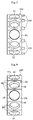
- the body 42 is formed into an annular shape, specifically, into a cylindrical shape in the illustrated example. As illustrated in FIG. 2 , a plurality of pocket holes 42a are formed equiangularly through the body 42, and one ball 30 is received in each pocket hole 42a.
- the body 42 is made of a material that is higher in strength than the resin portion 44, such as resin composites and metals.
- resin composites there may be used fiber-reinforced plastic materials such as CFRP and GFRP.
- the metals there may be used ingot materials or sinteredmetals of, for example, an aluminum alloy, a magnesium alloy, carbon steel, stainless steel, and a copper alloy.
- bearings to be used under environments of high speed rotation it is preferred that materials having high specific strength be used.
- materials having high specific strength there are given, for example, CFRP, GFRP, an aluminum alloy, a titanium alloy, and a magnesium alloy.
- materials having low hydrogen reactivity there are given, for example, CFRP, GFRP, and an aluminum alloy.
- materials having low oxidative reactivity there is given, for example, GFRP.
- the resin portion 44 is formed through injection molding with the body 42 being set as an insert component so that first parts 44a and a second part 44b are formed integrally with each other.
- the first parts 44a are formed along inner peripheral surfaces of the pocket holes 42a of the body 42. In the illustrated example, the first part 44a covers the entire cylindrical inner peripheral surface of the pocket hole 42a.
- a surface (inner peripheral surface) of the first part 44a formed in each of the pocket holes 42a functions as a pocket surface 46 to be held in sliding contact with the rolling element 30.
- the second part 44b is formed along an outer peripheral surface of the body 42. In the illustrated example, the second part 44b covers the entire cylindrical outer peripheral surface of the body 42.
- a surface (outer peripheral surface) of the second part 44b functions as a guide surface 48 to be held in sliding contact with the inner peripheral surface of the outer ring 20.
- a thickness of the first parts 44a and a thickness of the second part 44b are equal to each other. It is preferred that the thicknesses be set to 0.1 mm or more in consideration of fluidity at the time of the injection molding, more preferably, 0.2 mm or more in consideration of reliability of abrasion resistance.
- weld lines W are formed in the resin portion 44.
- the weld lines W are formed at positions of avoiding exposure at both end portions of the pocket surfaces 46 in a cage circumferential direction.
- the weld lines W are formed only on one side of the pocket surface 46 in the cage axial direction (left side in FIG. 3 ).
- the weld lines W are formed at circumferential positions corresponding to central portions of the pocket surfaces 46 in the cage circumferential direction, and extend substantially in the cage axial direction.
- One end of the weld line W is exposed to one end surface of the second part 44b in the cage axial direction, and another end of the weld line W is exposed to one end portion of the pocket surface 46 in the cage axial direction.
- the resin portion 44 is made of a resin containing a solid lubricant.
- a main-component resin thereof there may be used thermoplastic resins such as polyether ether ketone (PEEK), polyphenylene sulfide (PPS), and polyamide (PA).
- PEEK polyether ether ketone
- PPS polyphenylene sulfide
- PA polyamide
- PEEK polyether ether ketone
- PPS polyphenylene sulfide
- PA polyamide
- the solid lubricant there may be used a fluorine resin (such as PTFE), molybdenum disulfide, graphite, and the like.
- the resin forming the resin portion 44 may be blended with a reinforcing material. It is desired that the reinforcing material having effects of enhancing abrasion resistance and suppressing a linear expansion coefficient of the cage be used.
- a glass fiber (GF), a carbon fiber (CF), and magnesium oxide may be used. Note that, the reinforcing material may be omitted.
- the main-component resin (thermoplastic resin) of the above-mentioned resin be blended at 45 vol% or more so that the injection molding can be performed.
- the solid lubricant needs to be blended at 5 vol% or more.
- the solid lubricant be blended at 20 vol% or more.
- a blending ratio of the solid lubricant exceeds 40 vol%, the solid lubricant is hardly mixed with the main-component resin at the time of kneading. As a result, dispersibility at the time of the injection molding is deteriorated.
- the blending ratio of the solid lubricant be set to from 20 vol% to 40 vol%.
- the reinforcing material may be blended at a ratio of from 0 vol% to 15 vol% in accordance with required abrasion resistance and linear expansion coefficient. Therefore, in the above-mentioned resin, for example, the main-component resin is blended at a ratio of from 45 vol% to 80 vol%, the solid lubricant is blended at a ratio of from 20 vol% to 40 vol%, and the reinforcing material is blended at a ratio of from 0 vol% to 15 vol%.
- the friction coefficients of the pins 102 that is, lubricities of the resin composites are shown, and the friction coefficients are decreased when the blending ratio of PTFE is 20 vol% or more.
- the abrasion amounts of the ball 103 that is, lubricities of the transfer films 104 are shown, and the abrasion amounts are substantially uniform when the blending ratio of PTFE is 20 vol% or more as in FIG. 17 . Based on the results, it was confirmed that the preferred blending ratio of the solid lubricant particularly under the ultra-low-temperature environment was 20 vol% or more.
- the pocket surfaces 46 of the cage 40 and the balls 30 are held in sliding contact with each other, and the guide surface 48 (outer peripheral surface) of the cage 40 and the inner peripheral surface (shoulder surfaces) of the outer ring 20 are held in sliding contact with each other.
- the solid lubricant on the resin portion 44 is transferred onto the surfaces of the balls 30 and the shoulder surfaces of the outer ring 20, and hence lubrication is performed between the cage 40, the balls 30, and the outer ring 20. Further, lubrication is performed between the balls 30 and the raceway surface 12 of the inner ring 10 and between the balls 30 and the raceway surface 22 of the outer ring 20 by the solid lubricant transferred onto the balls 30.
- the strength of the cage 40 can be secured with the body 42.
- the reinforcing material to be blended into the resin of the resin portion 44 can be reduced or omitted.
- a large amount of the reinforcing material contained in the resinportion 44 is not exposed on the pocket surfaces 46 or the guide surface 48.
- the transfer of the solid lubricant from the resin portion 44 to the sliding contact counterparts (balls 30 or outer ring 20) is not hindered, and hence the lubricity can be enhanced.
- the body 42 is formed.
- the body 42 is made of a resin composite of a resin that contains reinforcing fiber such as carbon fiber and glass fiber.
- the body 42 is made of a metal (ingot material) through machining (such as cutting) or plastic working (press working or forging) of the metal.
- the body 42 is made of a sintered metal through sintering of a green compact formed by compressing mixed metal powder at a predetermined sintering temperature.
- fine recessed portions are formed in the surface of the body 42.
- the fine recessed portions are formed through surface roughening such as etching processes (sodium etching, plasma etching, and the like), shot-blasting, and thermal spraying. It is preferred that the body 42 after the surface roughening have a surface roughness larger than an amount of a dimensional variation in a cage radial direction due to a difference in linear expansion coefficient between the body 42 and the resin portion 44.
- the resin portion 44 is made of a GF-reinforced PEEK-based material (having a linear expansion coefficient of 34 ⁇ 10 -6 [1/°C]), and when the pocket surfaces 46 each have a diameter of 8 mm, it is desired that the body 42 have a surface roughness Ra of 10 ⁇ m or more. Note that, the surface roughening may be omitted. For example, when the body 42 is made of the sintered metal, numerous fine pores are formed in the surface of the body 42. For this reason, the surface roughing is not necessary.
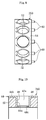
- FIG. 4 and FIG. 5 A cavity 50 of an injection molding die to be used at this time is illustrated in FIG. 4 and FIG. 5 .
- the cavity 50 comprises first cavities 52 for forming the first parts 44a of the resin portion 44, and a second cavity 54 for forming the second part 44b.
- a gate 60 is formed along a molding surface for forming the second cavity 54, specifically, along a molding surface for forming another end surface of the second part 44b in the cage axial direction (right side in FIG. 4 and FIG. 5 ).
- the gate 60 of this embodiment is an annular disc gate extending in the cage axial direction from an entire periphery of a radially outer end of a disc-like runner 62.
- FIG. 5 is a view for illustrating a state in which the cavity 50, the gate 60, and the runner 62 are filled with a resin (indicated by a dotted pattern).
- the resin When the resin is injected into the cavity 50 through the gate 60, the resin flows as indicated by the dotted-line arrows in FIG. 4 , and streams of the resin merge at positions on one side of the first cavities 52 in the cage axial direction (left side in FIG. 4 ).
- the weld lines W are formed at those merging parts (refer to FIG. 3 ). Further, the molten resin enters the fine recessed portions in the surface of the body 42 and is cured therein. With this, the body 42 and the resin portion 44 are firmly fixed to each other.
- the die is opened so that the cage 40 is taken out.
- the resin cured in the gate 60 is torn off.
- gate cutting marks are left in the cage 40.
- gate cutting marks are annularly left along the another end surface of the second part 44b of the resin portion 44 in the cage axial direction.
- machining is performed on the another end surface of the cage 40 in the axial direction, to thereby remove the gate cutting marks. Further, machining may be performed so as to finish one or both the pocket surfaces 46 and the guide surface 48, or an entire surface of the cage 40. Note that, unless particularly necessary, the above-mentioned machining may be omitted.
- a cage 140 illustrated in FIG. 6 is different from the cage of the embodiment described above in position of the weld lines W. Specifically, the weld lines W are formed on both sides of each of the pocket surfaces 46 in the cage axial direction.
- a cavity 150 for forming the resin portion 44 of the cage 140 is illustrated in FIG. 7 .
- Gates 60 of this embodiment are pin gates, which are arranged along a molding surface for forming the cavity 150, specifically, along a molding surface for forming the another end surface of the second part 44b in the cage axial direction (right side in FIG. 7 ). The gates 60 are arranged at a plurality of equiangular positions.
- the gates 60 are arranged correspondingly to circumferential regions between the plurality of first cavities 52 for forming the pocket surfaces 46.
- the resin flows as indicated by the dotted-line arrows in FIG. 7 , and streams of the resin merge at positions on both sides of the first cavities 52 in the cage axial direction.
- the weld lines W are formed at those merging parts (refer to FIG. 6 ).
- a cage 240 illustrated in FIG. 8 is different from the cages of the embodiments described above in position of the weld lines W.
- the weld lines W are formed at column portions 49 between the pocket surfaces 46 in the cage circumferential direction, and on the one side of each of the pocket surfaces 46 in the cage axial direction (left side in FIG. 8 ).
- a cavity 250 for forming the resin portion 44 of the cage 240 is illustrated in FIG. 9 .
- Gates 60 of this embodiment are pin gates, which are arranged along a molding surface for forming the cavity 250, specifically, along a molding surface for forming the another end surface of the second part 44b in the cage axial direction (right side in FIG. 9 ).
- the gates 60 are arranged at a plurality of equiangular positions.
- the gates 60 are arranged at circumferential positions corresponding to the central portions in the cage circumferential direction between the plurality of first cavities 52 for forming the pocket surfaces 46.
- the resin is injected through the gates 60, the resin flows around the first cavities 52 as indicated by the dotted-line arrows in FIG. 9 , and streams of the resin merge at positions between the first cavities 52 in the cage circumferential direction and on the one side of the first cavities 52 in the cage axial direction.
- the weld lines W are formed at those merging parts (refer to FIG. 8 ).
- a cage 340 illustrated in FIG. 10 is different from the cages of the embodiments described above in that projections 44c are formed so as to prevent the balls 30 from dropping off.
- the projection 44c is formed so as to project to a radially inner side of the pocket surface 46 along an end portion of the first part 44a of the resin portion 44 on a cage radially inner side.
- the projection 44c is formed along an entire periphery of the pocket surface 46.
- the projection 44c may be formed at a plurality of positions spaced apart from each other in a circumferential direction of the pocket surface 46.
- FIG. 11 is a side view for illustrating a cage 440 according to yet another embodiment of the present invention as viewed from the radially inner side.
- the cage 440 is different from the cages of the embodiments described above in that a thickness T1 at both end portions of the first part 44a of the resin portion 44 in the cage circumferential direction is larger than a thickness T2 at both end portions thereof in the cage axial direction (T1>T2) .
- T1 thickness at both end portions of the first part 44a in the cage circumferential direction, which is easily brought into contact with the ball 30, is set larger, an allowable abrasion amount is increased to achieve higher reliability.
- a thickness T3 of an annular part on both sides of the pocket hole 42a in the cage axial direction can be accordingly increased in the body 42. With this, the strength against hoop stress can be increased.
- recessed portions are formed in the guide surface 48.
- liquid films for example, liquid films of propellant for turbopumps
- the raceway ring in this embodiment, inner peripheral surface of the outer ring 20
- lubricity and abrasion resistance are enhanced.
- a plurality of grooves 48a extending in the cage axial direction are formed as the recessed portions.
- the grooves 48a are formed in a stepped pattern at equal intervals in the cage circumferential direction.
- grooves 48b serving as the recessed portions are equiangularly formed in a herringbone pattern inclined in symmetry with respect to a cage axial center.
- the surface illustrated in FIG. 12(b) is rotated in the direction of the arrow, when the grooves 48b are inclined so as to be spread on a forward side in the rotation direction toward both end portions in the cage axial direction as in the illustration, the liquid films are supplied toward the cage axial center along with the rotation of the cage 640. With this, lubricity can be enhanced.
- dimple-like recessed portions 48c are formed in the guide surface 48 of the cage 740 of FIG. 12(c) .
- relatively short grooves 48d serving as the recessed portions are arranged in a distributed pattern.
- the grooves 48d in the illustrated example extend in the cage axial direction. Note that, although similar weld lines W to those described above are formed in each of the cages 540 to 840 of FIGS. 12 , the illustration of the weld lines W is omitted.
- a most advantageous effect can be obtained when a depth of each of the recessed portions described above is set to from approximately 1 um to approximately 4 ⁇ m.
- the depth be set approximately equivalent to the gap between the guide surface 48 and the outer ring 20 in FIG. 1 , specifically, set to 50 ⁇ m or less.
- the recessed portions as described above can be formed at the time of injection molding. Further, the recessed portions as described above may be formed also through machining (such as lathing) or shot-blasting of the guide surface after the resin portion 44 is formed.
- a cage 940 illustrated in FIG. 13 is different from the cages of the embodiments described above in pattern of the recessed portions to be formed in the surface of the body 42.
- annular grooves 42b serving as the recessed portions are formed continuously along the cage circumferential direction.
- annular groove 42c serving as the recessed portion is formed continuously along the circumferential direction of the pocket hole 42a.
- Those grooves 42b and 42c are formed, for example, through machining or plastic working.
- the recessed portions to be formed in the body 42 may be grooves extending in directions other than the directions described above, and dimple-like recessed portions. Further, the recessed portions may be formed in any one of the outer peripheral surface of the body 42 and the inner peripheral surface of each of the pocket holes 42a. Still further, as illustrated in FIG. 14 , when a width of each of the recessed portions 42b and 42c is set smaller on a depth side than on an opening side, an effect of retaining the resin portion 44 can be enhanced. Yet further, when the above-mentioned surface roughening is performed not only on the grooves 42b and 42c but also on the surface of the body 42, the body 42 and the resin portion 44 are more firmly fixed to each other.
- the outer ring-guide rolling bearings configured to guide the cage 40 by bringing the cage 40 into sliding contact with the inner peripheral surface of the outer ring 20 are illustrated.
- the present invention is not limited thereto, and is applicable also to an inner ring-guide rolling bearings configured to guide the cage 40 by bringing the cage 40 into sliding contact with the outer peripheral surface of the inner ring 10.
- the second part 44b of the resin portion 44 is formed along an inner peripheral surface of the body 42, and the inner peripheral surface of the second part 44b functions as the guide surface 48 (not shown).
- FIG. 15 A turbopump for rocket engines having the angular contact ball bearings 1 descried above built therein is illustrated in FIG. 15 .
- this turbopump is configured to compress a liquid oxygen gas.
- this staged combustion rocket engine also comprises a similar turbopump configured to compress a liquid hydrogen gas.
- a turbine shaft 71 of the turbopump is configured to be initially driven by a combustion gas of the liquid fuel, which enters a preburner pump inlet and flows to a preburner pump outlet, and then fully driven by the combustion gas of the liquid fuel, which enters a turbine gas inlet and flows to a turbine gas outlet.
- the turbine shaft 71 is made of a nickel-based superalloy having high fatigue strength under ultra-low temperature, such as an Inconel material.
- the turbine shaft 71 is supported by double-row angular contact ball bearings 72 each obtained by combining two angular contact ball bearings 1.
- contact angles are formed in symmetry with respect to a plane orthogonal to an axis.
- the angular contact ball bearing 1 described above is applicable not only to the turbopump for rocket engines, but also to other uses.
- the angular contact ball bearing 1 described above may be built into apparatus to be used in vacuum environments, such as space apparatus including artificial satellites.
- the angular contact ball bearing 1 described above is not limited to use under the ultra-low-temperature environments, and may be used, for example, under environments of a normal temperature or higher.
- the angular contact ball bearings are described as rolling bearings according to the present invention, but the present invention is not limited thereto.
- the present invention is applicable also to ball bearings of other types, and to roller bearings such as a cylindrical roller bearing and a tapered roller bearing.
Applications Claiming Priority (2)
| Application Number | Priority Date | Filing Date | Title |
|---|---|---|---|
| JP2013115497A JP6178117B2 (ja) | 2013-05-31 | 2013-05-31 | 転がり軸受用保持器、転がり軸受、及び転がり軸受用保持器の製造方法 |
| PCT/JP2014/062127 WO2014192503A1 (ja) | 2013-05-31 | 2014-05-02 | 転がり軸受用保持器、転がり軸受、及び転がり軸受用保持器の製造方法 |
Publications (3)
| Publication Number | Publication Date |
|---|---|
| EP3006753A1 true EP3006753A1 (de) | 2016-04-13 |
| EP3006753A4 EP3006753A4 (de) | 2016-11-30 |
| EP3006753B1 EP3006753B1 (de) | 2018-11-07 |
Family
ID=51988541
Family Applications (1)
| Application Number | Title | Priority Date | Filing Date |
|---|---|---|---|
| EP14803334.3A Not-in-force EP3006753B1 (de) | 2013-05-31 | 2014-05-02 | Wälzlagerkäfig, wälzlager und verfahren zur herstellung eines wälzlagerkäfigs |
Country Status (5)
| Country | Link |
|---|---|
| US (1) | US9657779B2 (de) |
| EP (1) | EP3006753B1 (de) |
| JP (1) | JP6178117B2 (de) |
| CN (1) | CN105247231B (de) |
| WO (1) | WO2014192503A1 (de) |
Cited By (3)
| Publication number | Priority date | Publication date | Assignee | Title |
|---|---|---|---|---|
| DE102016200348A1 (de) * | 2016-01-14 | 2017-07-20 | Schaeffler Technologies AG & Co. KG | Wälzlagerkäfig und Spindellager mit einem solchen Wälzlagerkäfig |
| WO2018010718A1 (de) * | 2016-07-13 | 2018-01-18 | Schaeffler Technologies AG & Co. KG | Wälzkörpergeführter wälzlagerkäfig sowie wälzlager umfassend einen solchen wälzlagerkäfig |
| FR3112826A1 (fr) * | 2020-07-27 | 2022-01-28 | Safran Aircraft Engines | Cage de roulement à gorges de drainage |
Families Citing this family (24)
| Publication number | Priority date | Publication date | Assignee | Title |
|---|---|---|---|---|
| JP2016148417A (ja) * | 2015-02-13 | 2016-08-18 | Ntn株式会社 | 転がり軸受 |
| JP6601034B2 (ja) * | 2015-07-24 | 2019-11-06 | 株式会社ジェイテクト | 軸受装置 |
| JP6565570B2 (ja) * | 2015-10-08 | 2019-08-28 | 中西金属工業株式会社 | 外輪案内樹脂保持器及び射出成形用金型、並びに外輪案内樹脂保持器の製造方法 |
| WO2017145384A1 (ja) * | 2016-02-26 | 2017-08-31 | 日本精工株式会社 | 軸受用保持器の製造方法 |
| JP2017172736A (ja) * | 2016-03-24 | 2017-09-28 | Ntn株式会社 | 軸受用樹脂製保持器およびその製造方法、並びに転がり軸受 |
| JP6864437B2 (ja) * | 2016-03-25 | 2021-04-28 | Ntn株式会社 | 転がり軸受 |
| GB2550420A (en) | 2016-05-20 | 2017-11-22 | Bowman Int Ltd | Rolling element bearing cage |
| CN107939829B (zh) * | 2016-08-23 | 2019-05-17 | 扬州英泰机械有限公司 | 一种电机轴承 |
| JP6764741B2 (ja) * | 2016-09-23 | 2020-10-07 | 株式会社Ihi | 保持器及びその製造方法、並びに転がり軸受 |
| JP6933007B2 (ja) * | 2017-06-09 | 2021-09-08 | 株式会社ジェイテクト | タッチダウン軸受及びタッチダウン軸受の製造方法 |
| DE102017125700A1 (de) * | 2017-11-03 | 2019-05-09 | Schaeffler Technologies AG & Co. KG | Wälzlagerkäfig, Verfahren zur Herstellung eines Wälzlagerkäfigs und Verwendung eines Schiebers |
| CN108099213A (zh) * | 2017-12-12 | 2018-06-01 | 珠海格力智能装备有限公司 | 轴承热焊机及具有其的轴承组装设备 |
| JP7236902B2 (ja) * | 2018-03-30 | 2023-03-10 | Ntn株式会社 | 樹脂製保持器及び転がり軸受 |
| US10837488B2 (en) | 2018-07-24 | 2020-11-17 | Roller Bearing Company Of America, Inc. | Roller bearing assembly for use in a fracking pump crank shaft |
| JP7270446B2 (ja) | 2019-04-02 | 2023-05-10 | Ntn株式会社 | 転がり軸受 |
| US20220205485A1 (en) * | 2019-04-29 | 2022-06-30 | Schaeffler Technologies AG & Co. KG | An aluminum alloy cage and a processing method of the aluminum alloy cage |
| WO2020262029A1 (ja) | 2019-06-25 | 2020-12-30 | ミネベアミツミ株式会社 | 玉軸受 |
| CN113840987B (zh) * | 2019-06-25 | 2022-08-19 | 美蓓亚三美株式会社 | 球轴承 |
| JP7218703B2 (ja) * | 2019-10-08 | 2023-02-07 | 中西金属工業株式会社 | 両円環型樹脂保持器の製造方法 |
| US11009074B1 (en) * | 2019-11-11 | 2021-05-18 | Aktiebolaget Skf | Lightweight bearing cage for turbine engines and method of forming a lightweight bearing cage |
| CN111425524B (zh) * | 2020-03-31 | 2021-09-17 | 大连工业大学 | 一种滚动轴承用复合结构和材料的保持架 |
| FR3112371B1 (fr) * | 2020-07-10 | 2022-08-12 | Safran Aircraft Engines | Insert pour palier de roulement |
| CN113090663B (zh) * | 2021-04-01 | 2021-12-10 | 山东金帝精密机械科技股份有限公司 | 一种轴承保持器 |
| JP2023033016A (ja) | 2021-08-27 | 2023-03-09 | 国立研究開発法人宇宙航空研究開発機構 | 転がり軸受用保持器および転がり軸受 |
Family Cites Families (34)
| Publication number | Priority date | Publication date | Assignee | Title |
|---|---|---|---|---|
| US1996841A (en) * | 1931-05-06 | 1935-04-09 | Gen Motors Corp | Separator |
| US2550911A (en) * | 1945-08-30 | 1951-05-01 | Gen Motors Corp | Antifriction bearing |
| GB924420A (en) * | 1960-05-09 | 1963-04-24 | Barden Corp | Self lubricated ball bearing retainer |
| US3198735A (en) * | 1961-10-20 | 1965-08-03 | Edward R Lamson | Solid lubricant composition and method for lubricating anti-friction bearing structures |
| DE3424742C1 (de) * | 1984-07-05 | 1985-11-14 | SKF GmbH, 8720 Schweinfurt | Spritz- oder Gießform zur Herstellung eines Kunststoff-Taschenkäfigs für Radial-Zylinderrollenlager und Taschenkäfig, der in dieser Form hergestellt ist |
| JPH0648011B2 (ja) * | 1985-10-22 | 1994-06-22 | 日本精工株式会社 | 転がり軸受用保持器 |
| JPS62261718A (ja) | 1986-05-09 | 1987-11-13 | Natl Aerospace Lab | ガラス繊維強化型複合材料製軸受保持器の製造方法 |
| DE3718693A1 (de) * | 1987-06-04 | 1988-12-22 | Schaeffler Waelzlager Kg | Buchsenfoermiges spritzguss-bauteil, insbesondere waelzlagerkaefig |
| US4937180A (en) | 1988-04-08 | 1990-06-26 | Eastman Kodak Company | Photographic emulsions containing internally modified silver halide grains |
| JPH04321815A (ja) * | 1991-04-19 | 1992-11-11 | Nippon Seiko Kk | 転がり軸受 |
| JP3831507B2 (ja) * | 1998-01-14 | 2006-10-11 | 株式会社ジェイテクト | 軸受部材 |
| JP4003035B2 (ja) * | 2000-07-05 | 2007-11-07 | 日本精工株式会社 | 転がり軸受 |
| JP3819680B2 (ja) | 2000-07-06 | 2006-09-13 | 株式会社ジェイテクト | 転がり軸受用保持器およびその製造方法 |
| SE517535C2 (sv) * | 2000-12-21 | 2002-06-18 | Skf Ab | Rullningslager |
| DE10110915B4 (de) * | 2001-03-07 | 2010-04-01 | Schaeffler Kg | Käfig für ein Wälzlager |
| JP2002295479A (ja) * | 2001-03-29 | 2002-10-09 | Koyo Seiko Co Ltd | 軸受用保持器 |
| US6994474B2 (en) * | 2001-05-29 | 2006-02-07 | Nsk Ltd. | Rolling sliding member and rolling apparatus |
| JP2003065341A (ja) * | 2001-08-23 | 2003-03-05 | Koyo Seiko Co Ltd | 転がり軸受 |
| JP2003232363A (ja) * | 2002-02-07 | 2003-08-22 | Nsk Ltd | 転がり軸受 |
| JP2006220240A (ja) * | 2005-02-14 | 2006-08-24 | Ishikawajima Harima Heavy Ind Co Ltd | 極低温超高速転がり軸受 |
| JP4766051B2 (ja) * | 2005-11-18 | 2011-09-07 | 日本精工株式会社 | 樹脂製保持器及び転がり軸受 |
| JP5102964B2 (ja) | 2006-03-10 | 2012-12-19 | Ntn株式会社 | 樹脂製保持器および軸受 |
| JP2007321926A (ja) * | 2006-06-02 | 2007-12-13 | Nsk Ltd | 円錐ころ軸受用保持器およびその製造方法 |
| EP1881215A3 (de) * | 2006-07-12 | 2008-01-30 | JTEKT Corporation | Kunststoffkäfig für ein Wälzlager mit durch ringförmige Keramikeinlagen gebildeten Gleitflächen |
| JP5061921B2 (ja) * | 2008-01-24 | 2012-10-31 | 株式会社ジェイテクト | 転がり軸受の保持器 |
| JP5388277B2 (ja) * | 2009-02-20 | 2014-01-15 | Ntn株式会社 | 保持器、転がり軸受、保持器の製造方法および射出成形用の型 |
| JPWO2011135957A1 (ja) * | 2010-04-26 | 2013-07-18 | 日本精工株式会社 | 転がり軸受 |
| JP2012107703A (ja) * | 2010-11-17 | 2012-06-07 | Nsk Ltd | 転がり軸受用保持器及びその製造方法、並びに転がり軸受 |
| JP5741061B2 (ja) | 2011-02-28 | 2015-07-01 | 日本精工株式会社 | 転がり軸受用保持器及びその製造方法、並びに転がり軸受 |
| JP2012237445A (ja) * | 2011-04-27 | 2012-12-06 | Nsk Ltd | 転がり軸受 |
| JP2013046982A (ja) | 2011-08-29 | 2013-03-07 | Nsk Ltd | 円環状樹脂製品の製造方法、転がり軸受用樹脂保持器、転がり軸受、及び成形金型 |
| JP2013047553A (ja) * | 2011-08-29 | 2013-03-07 | Ntn Corp | 転がり軸受 |
| CN202597475U (zh) * | 2012-05-08 | 2012-12-12 | 聊城市新欣金帝保持器科技有限公司 | 一种含有有机耐磨层的铁质轴承保持器 |
| JP5957395B2 (ja) * | 2013-02-28 | 2016-07-27 | 日本ベアリング株式会社 | 転動体収容具 |
-
2013
- 2013-05-31 JP JP2013115497A patent/JP6178117B2/ja not_active Expired - Fee Related
-
2014
- 2014-05-02 US US14/893,113 patent/US9657779B2/en not_active Expired - Fee Related
- 2014-05-02 EP EP14803334.3A patent/EP3006753B1/de not_active Not-in-force
- 2014-05-02 CN CN201480029901.1A patent/CN105247231B/zh not_active Expired - Fee Related
- 2014-05-02 WO PCT/JP2014/062127 patent/WO2014192503A1/ja active Application Filing
Cited By (3)
| Publication number | Priority date | Publication date | Assignee | Title |
|---|---|---|---|---|
| DE102016200348A1 (de) * | 2016-01-14 | 2017-07-20 | Schaeffler Technologies AG & Co. KG | Wälzlagerkäfig und Spindellager mit einem solchen Wälzlagerkäfig |
| WO2018010718A1 (de) * | 2016-07-13 | 2018-01-18 | Schaeffler Technologies AG & Co. KG | Wälzkörpergeführter wälzlagerkäfig sowie wälzlager umfassend einen solchen wälzlagerkäfig |
| FR3112826A1 (fr) * | 2020-07-27 | 2022-01-28 | Safran Aircraft Engines | Cage de roulement à gorges de drainage |
Also Published As
| Publication number | Publication date |
|---|---|
| EP3006753B1 (de) | 2018-11-07 |
| CN105247231A (zh) | 2016-01-13 |
| JP6178117B2 (ja) | 2017-08-09 |
| US20160108965A1 (en) | 2016-04-21 |
| WO2014192503A1 (ja) | 2014-12-04 |
| EP3006753A4 (de) | 2016-11-30 |
| JP2014234846A (ja) | 2014-12-15 |
| CN105247231B (zh) | 2018-03-30 |
| US9657779B2 (en) | 2017-05-23 |
Similar Documents
| Publication | Publication Date | Title |
|---|---|---|
| EP3006753B1 (de) | Wälzlagerkäfig, wälzlager und verfahren zur herstellung eines wälzlagerkäfigs | |
| US9284982B2 (en) | Cage and rolling bearing | |
| EP1953400A1 (de) | Harzbehälter und wälzlager | |
| WO2015053348A1 (ja) | 保持器及び転がり軸受、並びに液化ガス用ポンプ | |
| EP2554865A1 (de) | Wälzlagervorrichtung | |
| JP2008196582A (ja) | 遊星回転体用円錐ころ軸受 | |
| US11773899B2 (en) | Rolling bearing | |
| JP2017180737A (ja) | 転がり軸受用保持器及び転がり軸受 | |
| EP3203099A1 (de) | Kugellagerkäfig | |
| JP2013072439A (ja) | 転がり軸受 | |
| JP2014029178A (ja) | 球面滑り軸受およびその製造方法 | |
| KR100660462B1 (ko) | 구면베어링 조립체 제조방법 | |
| JP2012007686A (ja) | 転がり軸受装置 | |
| JP2017166627A (ja) | アンギュラ玉軸受 | |
| US11378125B2 (en) | Valve and a manufacturing method of a bearing surface for a valve | |
| JP2017172664A (ja) | 固体潤滑転がり軸受 | |
| WO2023027130A1 (ja) | 転がり軸受用保持器および転がり軸受 | |
| JP6668098B2 (ja) | 流体動圧軸受装置 | |
| JP2013047553A (ja) | 転がり軸受 | |
| JP2013076469A (ja) | 転がり摺動部材及び転がり軸受並びに転がり摺動部材の製造方法 | |
| JP2013113423A (ja) | ボールねじ、射出成形機 | |
| JP5692719B2 (ja) | 球面滑り軸受およびその製造方法 | |
| JP2017172663A (ja) | 転がり軸受用保持器及び転がり軸受 | |
| JP6764741B2 (ja) | 保持器及びその製造方法、並びに転がり軸受 | |
| JP2017172678A (ja) | 極低温環境用転がり軸受 |
Legal Events
| Date | Code | Title | Description |
|---|---|---|---|
| PUAI | Public reference made under article 153(3) epc to a published international application that has entered the european phase |
Free format text: ORIGINAL CODE: 0009012 |
|
| 17P | Request for examination filed |
Effective date: 20151222 |
|
| AK | Designated contracting states |
Kind code of ref document: A1 Designated state(s): AL AT BE BG CH CY CZ DE DK EE ES FI FR GB GR HR HU IE IS IT LI LT LU LV MC MK MT NL NO PL PT RO RS SE SI SK SM TR |
|
| AX | Request for extension of the european patent |
Extension state: BA ME |
|
| DAX | Request for extension of the european patent (deleted) | ||
| A4 | Supplementary search report drawn up and despatched |
Effective date: 20161103 |
|
| RIC1 | Information provided on ipc code assigned before grant |
Ipc: F16C 33/38 20060101AFI20161027BHEP Ipc: F16C 33/44 20060101ALI20161027BHEP Ipc: B29C 45/14 20060101ALI20161027BHEP Ipc: B29C 45/27 20060101ALI20161027BHEP Ipc: F16C 33/46 20060101ALI20161027BHEP Ipc: F16C 19/06 20060101ALI20161027BHEP |
|
| GRAP | Despatch of communication of intention to grant a patent |
Free format text: ORIGINAL CODE: EPIDOSNIGR1 |
|
| STAA | Information on the status of an ep patent application or granted ep patent |
Free format text: STATUS: GRANT OF PATENT IS INTENDED |
|
| INTG | Intention to grant announced |
Effective date: 20180517 |
|
| GRAS | Grant fee paid |
Free format text: ORIGINAL CODE: EPIDOSNIGR3 |
|
| GRAA | (expected) grant |
Free format text: ORIGINAL CODE: 0009210 |
|
| STAA | Information on the status of an ep patent application or granted ep patent |
Free format text: STATUS: THE PATENT HAS BEEN GRANTED |
|
| AK | Designated contracting states |
Kind code of ref document: B1 Designated state(s): AL AT BE BG CH CY CZ DE DK EE ES FI FR GB GR HR HU IE IS IT LI LT LU LV MC MK MT NL NO PL PT RO RS SE SI SK SM TR |
|
| REG | Reference to a national code |
Ref country code: GB Ref legal event code: FG4D |
|
| REG | Reference to a national code |
Ref country code: CH Ref legal event code: EP Ref country code: AT Ref legal event code: REF Ref document number: 1062403 Country of ref document: AT Kind code of ref document: T Effective date: 20181115 |
|
| REG | Reference to a national code |
Ref country code: DE Ref legal event code: R096 Ref document number: 602014035671 Country of ref document: DE |
|
| REG | Reference to a national code |
Ref country code: IE Ref legal event code: FG4D |
|
| REG | Reference to a national code |
Ref country code: NL Ref legal event code: MP Effective date: 20181107 |
|
| REG | Reference to a national code |
Ref country code: LT Ref legal event code: MG4D |
|
| REG | Reference to a national code |
Ref country code: AT Ref legal event code: MK05 Ref document number: 1062403 Country of ref document: AT Kind code of ref document: T Effective date: 20181107 |
|
| PG25 | Lapsed in a contracting state [announced via postgrant information from national office to epo] |
Ref country code: NO Free format text: LAPSE BECAUSE OF FAILURE TO SUBMIT A TRANSLATION OF THE DESCRIPTION OR TO PAY THE FEE WITHIN THE PRESCRIBED TIME-LIMIT Effective date: 20190207 Ref country code: LT Free format text: LAPSE BECAUSE OF FAILURE TO SUBMIT A TRANSLATION OF THE DESCRIPTION OR TO PAY THE FEE WITHIN THE PRESCRIBED TIME-LIMIT Effective date: 20181107 Ref country code: BG Free format text: LAPSE BECAUSE OF FAILURE TO SUBMIT A TRANSLATION OF THE DESCRIPTION OR TO PAY THE FEE WITHIN THE PRESCRIBED TIME-LIMIT Effective date: 20190207 Ref country code: HR Free format text: LAPSE BECAUSE OF FAILURE TO SUBMIT A TRANSLATION OF THE DESCRIPTION OR TO PAY THE FEE WITHIN THE PRESCRIBED TIME-LIMIT Effective date: 20181107 Ref country code: IS Free format text: LAPSE BECAUSE OF FAILURE TO SUBMIT A TRANSLATION OF THE DESCRIPTION OR TO PAY THE FEE WITHIN THE PRESCRIBED TIME-LIMIT Effective date: 20190307 Ref country code: ES Free format text: LAPSE BECAUSE OF FAILURE TO SUBMIT A TRANSLATION OF THE DESCRIPTION OR TO PAY THE FEE WITHIN THE PRESCRIBED TIME-LIMIT Effective date: 20181107 Ref country code: LV Free format text: LAPSE BECAUSE OF FAILURE TO SUBMIT A TRANSLATION OF THE DESCRIPTION OR TO PAY THE FEE WITHIN THE PRESCRIBED TIME-LIMIT Effective date: 20181107 Ref country code: AT Free format text: LAPSE BECAUSE OF FAILURE TO SUBMIT A TRANSLATION OF THE DESCRIPTION OR TO PAY THE FEE WITHIN THE PRESCRIBED TIME-LIMIT Effective date: 20181107 Ref country code: FI Free format text: LAPSE BECAUSE OF FAILURE TO SUBMIT A TRANSLATION OF THE DESCRIPTION OR TO PAY THE FEE WITHIN THE PRESCRIBED TIME-LIMIT Effective date: 20181107 |
|
| PG25 | Lapsed in a contracting state [announced via postgrant information from national office to epo] |
Ref country code: GR Free format text: LAPSE BECAUSE OF FAILURE TO SUBMIT A TRANSLATION OF THE DESCRIPTION OR TO PAY THE FEE WITHIN THE PRESCRIBED TIME-LIMIT Effective date: 20190208 Ref country code: AL Free format text: LAPSE BECAUSE OF FAILURE TO SUBMIT A TRANSLATION OF THE DESCRIPTION OR TO PAY THE FEE WITHIN THE PRESCRIBED TIME-LIMIT Effective date: 20181107 Ref country code: RS Free format text: LAPSE BECAUSE OF FAILURE TO SUBMIT A TRANSLATION OF THE DESCRIPTION OR TO PAY THE FEE WITHIN THE PRESCRIBED TIME-LIMIT Effective date: 20181107 Ref country code: SE Free format text: LAPSE BECAUSE OF FAILURE TO SUBMIT A TRANSLATION OF THE DESCRIPTION OR TO PAY THE FEE WITHIN THE PRESCRIBED TIME-LIMIT Effective date: 20181107 Ref country code: NL Free format text: LAPSE BECAUSE OF FAILURE TO SUBMIT A TRANSLATION OF THE DESCRIPTION OR TO PAY THE FEE WITHIN THE PRESCRIBED TIME-LIMIT Effective date: 20181107 Ref country code: PT Free format text: LAPSE BECAUSE OF FAILURE TO SUBMIT A TRANSLATION OF THE DESCRIPTION OR TO PAY THE FEE WITHIN THE PRESCRIBED TIME-LIMIT Effective date: 20190307 |
|
| PG25 | Lapsed in a contracting state [announced via postgrant information from national office to epo] |
Ref country code: PL Free format text: LAPSE BECAUSE OF FAILURE TO SUBMIT A TRANSLATION OF THE DESCRIPTION OR TO PAY THE FEE WITHIN THE PRESCRIBED TIME-LIMIT Effective date: 20181107 Ref country code: IT Free format text: LAPSE BECAUSE OF FAILURE TO SUBMIT A TRANSLATION OF THE DESCRIPTION OR TO PAY THE FEE WITHIN THE PRESCRIBED TIME-LIMIT Effective date: 20181107 Ref country code: DK Free format text: LAPSE BECAUSE OF FAILURE TO SUBMIT A TRANSLATION OF THE DESCRIPTION OR TO PAY THE FEE WITHIN THE PRESCRIBED TIME-LIMIT Effective date: 20181107 Ref country code: CZ Free format text: LAPSE BECAUSE OF FAILURE TO SUBMIT A TRANSLATION OF THE DESCRIPTION OR TO PAY THE FEE WITHIN THE PRESCRIBED TIME-LIMIT Effective date: 20181107 |
|
| REG | Reference to a national code |
Ref country code: DE Ref legal event code: R097 Ref document number: 602014035671 Country of ref document: DE |
|
| PG25 | Lapsed in a contracting state [announced via postgrant information from national office to epo] |
Ref country code: RO Free format text: LAPSE BECAUSE OF FAILURE TO SUBMIT A TRANSLATION OF THE DESCRIPTION OR TO PAY THE FEE WITHIN THE PRESCRIBED TIME-LIMIT Effective date: 20181107 Ref country code: SK Free format text: LAPSE BECAUSE OF FAILURE TO SUBMIT A TRANSLATION OF THE DESCRIPTION OR TO PAY THE FEE WITHIN THE PRESCRIBED TIME-LIMIT Effective date: 20181107 Ref country code: EE Free format text: LAPSE BECAUSE OF FAILURE TO SUBMIT A TRANSLATION OF THE DESCRIPTION OR TO PAY THE FEE WITHIN THE PRESCRIBED TIME-LIMIT Effective date: 20181107 Ref country code: SM Free format text: LAPSE BECAUSE OF FAILURE TO SUBMIT A TRANSLATION OF THE DESCRIPTION OR TO PAY THE FEE WITHIN THE PRESCRIBED TIME-LIMIT Effective date: 20181107 |
|
| PLBE | No opposition filed within time limit |
Free format text: ORIGINAL CODE: 0009261 |
|
| STAA | Information on the status of an ep patent application or granted ep patent |
Free format text: STATUS: NO OPPOSITION FILED WITHIN TIME LIMIT |
|
| 26N | No opposition filed |
Effective date: 20190808 |
|
| PG25 | Lapsed in a contracting state [announced via postgrant information from national office to epo] |
Ref country code: SI Free format text: LAPSE BECAUSE OF FAILURE TO SUBMIT A TRANSLATION OF THE DESCRIPTION OR TO PAY THE FEE WITHIN THE PRESCRIBED TIME-LIMIT Effective date: 20181107 |
|
| REG | Reference to a national code |
Ref country code: CH Ref legal event code: PL |
|
| GBPC | Gb: european patent ceased through non-payment of renewal fee |
Effective date: 20190502 |
|
| PG25 | Lapsed in a contracting state [announced via postgrant information from national office to epo] |
Ref country code: MC Free format text: LAPSE BECAUSE OF FAILURE TO SUBMIT A TRANSLATION OF THE DESCRIPTION OR TO PAY THE FEE WITHIN THE PRESCRIBED TIME-LIMIT Effective date: 20181107 Ref country code: CH Free format text: LAPSE BECAUSE OF NON-PAYMENT OF DUE FEES Effective date: 20190531 Ref country code: LI Free format text: LAPSE BECAUSE OF NON-PAYMENT OF DUE FEES Effective date: 20190531 |
|
| REG | Reference to a national code |
Ref country code: BE Ref legal event code: MM Effective date: 20190531 |
|
| PG25 | Lapsed in a contracting state [announced via postgrant information from national office to epo] |
Ref country code: LU Free format text: LAPSE BECAUSE OF NON-PAYMENT OF DUE FEES Effective date: 20190502 |
|
| PG25 | Lapsed in a contracting state [announced via postgrant information from national office to epo] |
Ref country code: TR Free format text: LAPSE BECAUSE OF FAILURE TO SUBMIT A TRANSLATION OF THE DESCRIPTION OR TO PAY THE FEE WITHIN THE PRESCRIBED TIME-LIMIT Effective date: 20181107 |
|
| PG25 | Lapsed in a contracting state [announced via postgrant information from national office to epo] |
Ref country code: IE Free format text: LAPSE BECAUSE OF NON-PAYMENT OF DUE FEES Effective date: 20190502 Ref country code: GB Free format text: LAPSE BECAUSE OF NON-PAYMENT OF DUE FEES Effective date: 20190502 |
|
| PG25 | Lapsed in a contracting state [announced via postgrant information from national office to epo] |
Ref country code: BE Free format text: LAPSE BECAUSE OF NON-PAYMENT OF DUE FEES Effective date: 20190531 |
|
| PGFP | Annual fee paid to national office [announced via postgrant information from national office to epo] |
Ref country code: DE Payment date: 20200422 Year of fee payment: 7 Ref country code: FR Payment date: 20200414 Year of fee payment: 7 |
|
| PG25 | Lapsed in a contracting state [announced via postgrant information from national office to epo] |
Ref country code: CY Free format text: LAPSE BECAUSE OF FAILURE TO SUBMIT A TRANSLATION OF THE DESCRIPTION OR TO PAY THE FEE WITHIN THE PRESCRIBED TIME-LIMIT Effective date: 20181107 |
|
| PG25 | Lapsed in a contracting state [announced via postgrant information from national office to epo] |
Ref country code: MT Free format text: LAPSE BECAUSE OF FAILURE TO SUBMIT A TRANSLATION OF THE DESCRIPTION OR TO PAY THE FEE WITHIN THE PRESCRIBED TIME-LIMIT Effective date: 20181107 Ref country code: HU Free format text: LAPSE BECAUSE OF FAILURE TO SUBMIT A TRANSLATION OF THE DESCRIPTION OR TO PAY THE FEE WITHIN THE PRESCRIBED TIME-LIMIT; INVALID AB INITIO Effective date: 20140502 |
|
| REG | Reference to a national code |
Ref country code: DE Ref legal event code: R119 Ref document number: 602014035671 Country of ref document: DE |
|
| PG25 | Lapsed in a contracting state [announced via postgrant information from national office to epo] |
Ref country code: DE Free format text: LAPSE BECAUSE OF NON-PAYMENT OF DUE FEES Effective date: 20211201 |
|
| PG25 | Lapsed in a contracting state [announced via postgrant information from national office to epo] |
Ref country code: FR Free format text: LAPSE BECAUSE OF NON-PAYMENT OF DUE FEES Effective date: 20210531 |
|
| PG25 | Lapsed in a contracting state [announced via postgrant information from national office to epo] |
Ref country code: MK Free format text: LAPSE BECAUSE OF FAILURE TO SUBMIT A TRANSLATION OF THE DESCRIPTION OR TO PAY THE FEE WITHIN THE PRESCRIBED TIME-LIMIT Effective date: 20181107 |