EP2816958B1 - Determining material stiffness using multiple aperture ultrasound - Google Patents
Determining material stiffness using multiple aperture ultrasound Download PDFInfo
- Publication number
- EP2816958B1 EP2816958B1 EP13751662.1A EP13751662A EP2816958B1 EP 2816958 B1 EP2816958 B1 EP 2816958B1 EP 13751662 A EP13751662 A EP 13751662A EP 2816958 B1 EP2816958 B1 EP 2816958B1
- Authority
- EP
- European Patent Office
- Prior art keywords
- imaging
- ultrasound
- interest
- region
- shear wave
- Prior art date
- Legal status (The legal status is an assumption and is not a legal conclusion. Google has not performed a legal analysis and makes no representation as to the accuracy of the status listed.)
- Active
Links
- 238000002604 ultrasonography Methods 0.000 title claims description 78
- 239000000463 material Substances 0.000 title description 6
- 238000003384 imaging method Methods 0.000 claims description 129
- 238000000034 method Methods 0.000 claims description 111
- 238000002592 echocardiography Methods 0.000 claims description 40
- 230000001902 propagating effect Effects 0.000 claims description 35
- 238000012285 ultrasound imaging Methods 0.000 claims description 34
- 230000005540 biological transmission Effects 0.000 claims description 16
- 239000000523 sample Substances 0.000 description 71
- 210000001519 tissue Anatomy 0.000 description 63
- 230000008569 process Effects 0.000 description 51
- 238000002091 elastography Methods 0.000 description 38
- 238000003491 array Methods 0.000 description 35
- 230000000977 initiatory effect Effects 0.000 description 20
- 238000012545 processing Methods 0.000 description 19
- 238000005259 measurement Methods 0.000 description 11
- 230000006835 compression Effects 0.000 description 8
- 238000007906 compression Methods 0.000 description 8
- 230000006870 function Effects 0.000 description 7
- 238000002113 ultrasound elastography Methods 0.000 description 6
- 238000004458 analytical method Methods 0.000 description 5
- 238000010276 construction Methods 0.000 description 4
- 238000006073 displacement reaction Methods 0.000 description 4
- 238000001914 filtration Methods 0.000 description 4
- 230000033001 locomotion Effects 0.000 description 4
- 230000008901 benefit Effects 0.000 description 3
- 239000013078 crystal Substances 0.000 description 3
- 230000001934 delay Effects 0.000 description 3
- 210000000056 organ Anatomy 0.000 description 3
- 238000005070 sampling Methods 0.000 description 3
- 230000000007 visual effect Effects 0.000 description 3
- 238000012935 Averaging Methods 0.000 description 2
- 238000002126 acoustic radiation force impulse imaging Methods 0.000 description 2
- 230000009471 action Effects 0.000 description 2
- 238000004364 calculation method Methods 0.000 description 2
- 208000019425 cirrhosis of liver Diseases 0.000 description 2
- 239000003086 colorant Substances 0.000 description 2
- 201000010099 disease Diseases 0.000 description 2
- 208000037265 diseases, disorders, signs and symptoms Diseases 0.000 description 2
- 238000005516 engineering process Methods 0.000 description 2
- 230000005284 excitation Effects 0.000 description 2
- 230000003993 interaction Effects 0.000 description 2
- 238000002559 palpation Methods 0.000 description 2
- 238000004091 panning Methods 0.000 description 2
- 238000003825 pressing Methods 0.000 description 2
- 230000005855 radiation Effects 0.000 description 2
- 210000004872 soft tissue Anatomy 0.000 description 2
- 238000012360 testing method Methods 0.000 description 2
- 206010028980 Neoplasm Diseases 0.000 description 1
- 206010060862 Prostate cancer Diseases 0.000 description 1
- 208000000236 Prostatic Neoplasms Diseases 0.000 description 1
- 230000005856 abnormality Effects 0.000 description 1
- 230000015572 biosynthetic process Effects 0.000 description 1
- 201000011510 cancer Diseases 0.000 description 1
- 230000000747 cardiac effect Effects 0.000 description 1
- 238000012512 characterization method Methods 0.000 description 1
- 230000007882 cirrhosis Effects 0.000 description 1
- 230000001427 coherent effect Effects 0.000 description 1
- 238000004891 communication Methods 0.000 description 1
- 230000003750 conditioning effect Effects 0.000 description 1
- 230000001186 cumulative effect Effects 0.000 description 1
- 238000005520 cutting process Methods 0.000 description 1
- 238000013481 data capture Methods 0.000 description 1
- 238000013500 data storage Methods 0.000 description 1
- 238000001514 detection method Methods 0.000 description 1
- 238000002059 diagnostic imaging Methods 0.000 description 1
- 239000006185 dispersion Substances 0.000 description 1
- -1 earth Substances 0.000 description 1
- 230000000694 effects Effects 0.000 description 1
- 238000005530 etching Methods 0.000 description 1
- 238000011156 evaluation Methods 0.000 description 1
- 238000010304 firing Methods 0.000 description 1
- 210000005003 heart tissue Anatomy 0.000 description 1
- 230000001976 improved effect Effects 0.000 description 1
- 230000001939 inductive effect Effects 0.000 description 1
- 238000001990 intravenous administration Methods 0.000 description 1
- 230000003902 lesion Effects 0.000 description 1
- 239000007788 liquid Substances 0.000 description 1
- 210000005228 liver tissue Anatomy 0.000 description 1
- 238000004519 manufacturing process Methods 0.000 description 1
- 238000013507 mapping Methods 0.000 description 1
- 238000012986 modification Methods 0.000 description 1
- 230000004048 modification Effects 0.000 description 1
- 230000003387 muscular Effects 0.000 description 1
- 238000009659 non-destructive testing Methods 0.000 description 1
- 230000008520 organization Effects 0.000 description 1
- 230000001575 pathological effect Effects 0.000 description 1
- 230000007170 pathology Effects 0.000 description 1
- 230000010363 phase shift Effects 0.000 description 1
- 238000012805 post-processing Methods 0.000 description 1
- 238000004451 qualitative analysis Methods 0.000 description 1
- 238000004445 quantitative analysis Methods 0.000 description 1
- 238000012958 reprocessing Methods 0.000 description 1
- 210000002027 skeletal muscle Anatomy 0.000 description 1
- 239000002689 soil Substances 0.000 description 1
- 239000007787 solid Substances 0.000 description 1
- 230000001360 synchronised effect Effects 0.000 description 1
- 238000011179 visual inspection Methods 0.000 description 1
Images


Classifications
-
- A—HUMAN NECESSITIES
- A61—MEDICAL OR VETERINARY SCIENCE; HYGIENE
- A61B—DIAGNOSIS; SURGERY; IDENTIFICATION
- A61B8/00—Diagnosis using ultrasonic, sonic or infrasonic waves
- A61B8/48—Diagnostic techniques
- A61B8/485—Diagnostic techniques involving measuring strain or elastic properties
-
- A—HUMAN NECESSITIES
- A61—MEDICAL OR VETERINARY SCIENCE; HYGIENE
- A61B—DIAGNOSIS; SURGERY; IDENTIFICATION
- A61B8/00—Diagnosis using ultrasonic, sonic or infrasonic waves
- A61B8/44—Constructional features of the ultrasonic, sonic or infrasonic diagnostic device
- A61B8/4444—Constructional features of the ultrasonic, sonic or infrasonic diagnostic device related to the probe
-
- A—HUMAN NECESSITIES
- A61—MEDICAL OR VETERINARY SCIENCE; HYGIENE
- A61B—DIAGNOSIS; SURGERY; IDENTIFICATION
- A61B8/00—Diagnosis using ultrasonic, sonic or infrasonic waves
- A61B8/13—Tomography
- A61B8/14—Echo-tomography
- A61B8/145—Echo-tomography characterised by scanning multiple planes
-
- A—HUMAN NECESSITIES
- A61—MEDICAL OR VETERINARY SCIENCE; HYGIENE
- A61B—DIAGNOSIS; SURGERY; IDENTIFICATION
- A61B8/00—Diagnosis using ultrasonic, sonic or infrasonic waves
- A61B8/44—Constructional features of the ultrasonic, sonic or infrasonic diagnostic device
- A61B8/4477—Constructional features of the ultrasonic, sonic or infrasonic diagnostic device using several separate ultrasound transducers or probes
-
- A—HUMAN NECESSITIES
- A61—MEDICAL OR VETERINARY SCIENCE; HYGIENE
- A61B—DIAGNOSIS; SURGERY; IDENTIFICATION
- A61B8/00—Diagnosis using ultrasonic, sonic or infrasonic waves
- A61B8/44—Constructional features of the ultrasonic, sonic or infrasonic diagnostic device
- A61B8/4483—Constructional features of the ultrasonic, sonic or infrasonic diagnostic device characterised by features of the ultrasound transducer
- A61B8/4488—Constructional features of the ultrasonic, sonic or infrasonic diagnostic device characterised by features of the ultrasound transducer the transducer being a phased array
-
- A—HUMAN NECESSITIES
- A61—MEDICAL OR VETERINARY SCIENCE; HYGIENE
- A61B—DIAGNOSIS; SURGERY; IDENTIFICATION
- A61B8/00—Diagnosis using ultrasonic, sonic or infrasonic waves
- A61B8/46—Ultrasonic, sonic or infrasonic diagnostic devices with special arrangements for interfacing with the operator or the patient
- A61B8/461—Displaying means of special interest
-
- A—HUMAN NECESSITIES
- A61—MEDICAL OR VETERINARY SCIENCE; HYGIENE
- A61B—DIAGNOSIS; SURGERY; IDENTIFICATION
- A61B8/00—Diagnosis using ultrasonic, sonic or infrasonic waves
- A61B8/52—Devices using data or image processing specially adapted for diagnosis using ultrasonic, sonic or infrasonic waves
- A61B8/5207—Devices using data or image processing specially adapted for diagnosis using ultrasonic, sonic or infrasonic waves involving processing of raw data to produce diagnostic data, e.g. for generating an image
-
- A—HUMAN NECESSITIES
- A61—MEDICAL OR VETERINARY SCIENCE; HYGIENE
- A61B—DIAGNOSIS; SURGERY; IDENTIFICATION
- A61B8/00—Diagnosis using ultrasonic, sonic or infrasonic waves
- A61B8/52—Devices using data or image processing specially adapted for diagnosis using ultrasonic, sonic or infrasonic waves
- A61B8/5215—Devices using data or image processing specially adapted for diagnosis using ultrasonic, sonic or infrasonic waves involving processing of medical diagnostic data
- A61B8/5238—Devices using data or image processing specially adapted for diagnosis using ultrasonic, sonic or infrasonic waves involving processing of medical diagnostic data for combining image data of patient, e.g. merging several images from different acquisition modes into one image
- A61B8/5246—Devices using data or image processing specially adapted for diagnosis using ultrasonic, sonic or infrasonic waves involving processing of medical diagnostic data for combining image data of patient, e.g. merging several images from different acquisition modes into one image combining images from the same or different imaging techniques, e.g. color Doppler and B-mode
-
- G—PHYSICS
- G01—MEASURING; TESTING
- G01S—RADIO DIRECTION-FINDING; RADIO NAVIGATION; DETERMINING DISTANCE OR VELOCITY BY USE OF RADIO WAVES; LOCATING OR PRESENCE-DETECTING BY USE OF THE REFLECTION OR RERADIATION OF RADIO WAVES; ANALOGOUS ARRANGEMENTS USING OTHER WAVES
- G01S15/00—Systems using the reflection or reradiation of acoustic waves, e.g. sonar systems
- G01S15/88—Sonar systems specially adapted for specific applications
- G01S15/89—Sonar systems specially adapted for specific applications for mapping or imaging
- G01S15/8906—Short-range imaging systems; Acoustic microscope systems using pulse-echo techniques
- G01S15/8909—Short-range imaging systems; Acoustic microscope systems using pulse-echo techniques using a static transducer configuration
- G01S15/8915—Short-range imaging systems; Acoustic microscope systems using pulse-echo techniques using a static transducer configuration using a transducer array
- G01S15/8922—Short-range imaging systems; Acoustic microscope systems using pulse-echo techniques using a static transducer configuration using a transducer array the array being concentric or annular
-
- G—PHYSICS
- G01—MEASURING; TESTING
- G01S—RADIO DIRECTION-FINDING; RADIO NAVIGATION; DETERMINING DISTANCE OR VELOCITY BY USE OF RADIO WAVES; LOCATING OR PRESENCE-DETECTING BY USE OF THE REFLECTION OR RERADIATION OF RADIO WAVES; ANALOGOUS ARRANGEMENTS USING OTHER WAVES
- G01S15/00—Systems using the reflection or reradiation of acoustic waves, e.g. sonar systems
- G01S15/88—Sonar systems specially adapted for specific applications
- G01S15/89—Sonar systems specially adapted for specific applications for mapping or imaging
- G01S15/8906—Short-range imaging systems; Acoustic microscope systems using pulse-echo techniques
- G01S15/8909—Short-range imaging systems; Acoustic microscope systems using pulse-echo techniques using a static transducer configuration
- G01S15/8929—Short-range imaging systems; Acoustic microscope systems using pulse-echo techniques using a static transducer configuration using a three-dimensional transducer configuration
-
- G—PHYSICS
- G01—MEASURING; TESTING
- G01S—RADIO DIRECTION-FINDING; RADIO NAVIGATION; DETERMINING DISTANCE OR VELOCITY BY USE OF RADIO WAVES; LOCATING OR PRESENCE-DETECTING BY USE OF THE REFLECTION OR RERADIATION OF RADIO WAVES; ANALOGOUS ARRANGEMENTS USING OTHER WAVES
- G01S15/00—Systems using the reflection or reradiation of acoustic waves, e.g. sonar systems
- G01S15/88—Sonar systems specially adapted for specific applications
- G01S15/89—Sonar systems specially adapted for specific applications for mapping or imaging
- G01S15/8906—Short-range imaging systems; Acoustic microscope systems using pulse-echo techniques
- G01S15/8979—Combined Doppler and pulse-echo imaging systems
-
- G—PHYSICS
- G01—MEASURING; TESTING
- G01S—RADIO DIRECTION-FINDING; RADIO NAVIGATION; DETERMINING DISTANCE OR VELOCITY BY USE OF RADIO WAVES; LOCATING OR PRESENCE-DETECTING BY USE OF THE REFLECTION OR RERADIATION OF RADIO WAVES; ANALOGOUS ARRANGEMENTS USING OTHER WAVES
- G01S15/00—Systems using the reflection or reradiation of acoustic waves, e.g. sonar systems
- G01S15/88—Sonar systems specially adapted for specific applications
- G01S15/89—Sonar systems specially adapted for specific applications for mapping or imaging
- G01S15/8906—Short-range imaging systems; Acoustic microscope systems using pulse-echo techniques
- G01S15/8993—Three dimensional imaging systems
-
- G—PHYSICS
- G01—MEASURING; TESTING
- G01S—RADIO DIRECTION-FINDING; RADIO NAVIGATION; DETERMINING DISTANCE OR VELOCITY BY USE OF RADIO WAVES; LOCATING OR PRESENCE-DETECTING BY USE OF THE REFLECTION OR RERADIATION OF RADIO WAVES; ANALOGOUS ARRANGEMENTS USING OTHER WAVES
- G01S15/00—Systems using the reflection or reradiation of acoustic waves, e.g. sonar systems
- G01S15/88—Sonar systems specially adapted for specific applications
- G01S15/89—Sonar systems specially adapted for specific applications for mapping or imaging
- G01S15/8906—Short-range imaging systems; Acoustic microscope systems using pulse-echo techniques
- G01S15/8997—Short-range imaging systems; Acoustic microscope systems using pulse-echo techniques using synthetic aperture techniques
-
- G—PHYSICS
- G01—MEASURING; TESTING
- G01S—RADIO DIRECTION-FINDING; RADIO NAVIGATION; DETERMINING DISTANCE OR VELOCITY BY USE OF RADIO WAVES; LOCATING OR PRESENCE-DETECTING BY USE OF THE REFLECTION OR RERADIATION OF RADIO WAVES; ANALOGOUS ARRANGEMENTS USING OTHER WAVES
- G01S7/00—Details of systems according to groups G01S13/00, G01S15/00, G01S17/00
- G01S7/52—Details of systems according to groups G01S13/00, G01S15/00, G01S17/00 of systems according to group G01S15/00
- G01S7/52017—Details of systems according to groups G01S13/00, G01S15/00, G01S17/00 of systems according to group G01S15/00 particularly adapted to short-range imaging
- G01S7/52019—Details of transmitters
- G01S7/5202—Details of transmitters for pulse systems
- G01S7/52022—Details of transmitters for pulse systems using a sequence of pulses, at least one pulse manipulating the transmissivity or reflexivity of the medium
-
- G—PHYSICS
- G01—MEASURING; TESTING
- G01S—RADIO DIRECTION-FINDING; RADIO NAVIGATION; DETERMINING DISTANCE OR VELOCITY BY USE OF RADIO WAVES; LOCATING OR PRESENCE-DETECTING BY USE OF THE REFLECTION OR RERADIATION OF RADIO WAVES; ANALOGOUS ARRANGEMENTS USING OTHER WAVES
- G01S7/00—Details of systems according to groups G01S13/00, G01S15/00, G01S17/00
- G01S7/52—Details of systems according to groups G01S13/00, G01S15/00, G01S17/00 of systems according to group G01S15/00
- G01S7/52017—Details of systems according to groups G01S13/00, G01S15/00, G01S17/00 of systems according to group G01S15/00 particularly adapted to short-range imaging
- G01S7/52023—Details of receivers
- G01S7/52036—Details of receivers using analysis of echo signal for target characterisation
- G01S7/52042—Details of receivers using analysis of echo signal for target characterisation determining elastic properties of the propagation medium or of the reflective target
-
- G—PHYSICS
- G03—PHOTOGRAPHY; CINEMATOGRAPHY; ANALOGOUS TECHNIQUES USING WAVES OTHER THAN OPTICAL WAVES; ELECTROGRAPHY; HOLOGRAPHY
- G03B—APPARATUS OR ARRANGEMENTS FOR TAKING PHOTOGRAPHS OR FOR PROJECTING OR VIEWING THEM; APPARATUS OR ARRANGEMENTS EMPLOYING ANALOGOUS TECHNIQUES USING WAVES OTHER THAN OPTICAL WAVES; ACCESSORIES THEREFOR
- G03B42/00—Obtaining records using waves other than optical waves; Visualisation of such records by using optical means
- G03B42/06—Obtaining records using waves other than optical waves; Visualisation of such records by using optical means using ultrasonic, sonic or infrasonic waves
-
- A—HUMAN NECESSITIES
- A61—MEDICAL OR VETERINARY SCIENCE; HYGIENE
- A61B—DIAGNOSIS; SURGERY; IDENTIFICATION
- A61B8/00—Diagnosis using ultrasonic, sonic or infrasonic waves
- A61B8/48—Diagnostic techniques
- A61B8/488—Diagnostic techniques involving Doppler signals
-
- G—PHYSICS
- G01—MEASURING; TESTING
- G01S—RADIO DIRECTION-FINDING; RADIO NAVIGATION; DETERMINING DISTANCE OR VELOCITY BY USE OF RADIO WAVES; LOCATING OR PRESENCE-DETECTING BY USE OF THE REFLECTION OR RERADIATION OF RADIO WAVES; ANALOGOUS ARRANGEMENTS USING OTHER WAVES
- G01S15/00—Systems using the reflection or reradiation of acoustic waves, e.g. sonar systems
- G01S15/88—Sonar systems specially adapted for specific applications
- G01S15/89—Sonar systems specially adapted for specific applications for mapping or imaging
- G01S15/8906—Short-range imaging systems; Acoustic microscope systems using pulse-echo techniques
- G01S15/8959—Short-range imaging systems; Acoustic microscope systems using pulse-echo techniques using coded signals for correlation purposes
Definitions
- This disclosure generally relates to imaging methods and devices for determining a material stiffness using a multiple aperture ultrasound probe to produce and track ultrasonic shear waves.
- Hard tissues have a higher Young's modulus than soft tissues. Being able to measure the Young's modulus of a tissue helps a physician in differentiating between benign and malignant tumors, detecting liver fibrosis and cirrhosis, detecting prostate cancer lesions, etc.
- Elastography A collection of diagnostic and imaging modalities and processing techniques have been developed to allow clinicians to evaluate tissue stiffness using ultrasonography. These techniques are collectively referred to herein as Elastography. In addition to providing information about tissue stiffness, some elastography techniques may also be used to reveal other stiffness properties of tissue, such as axial strain, lateral strain, Poisson's Ratio, and other common strain and strain-related parameters. Any of these or other strain-related parameters may be displayed in shaded grayscale or color displays to provide visual representations of such strain-related parameters. Such information may be displayed in relation to two or three dimensional data.
- Elastography techniques may be broadly divided into two categories, “quasi-static elastography” techniques and “dynamic elastography” techniques.
- tissue strain is induced by mechanical compression of a tissue region of interest, such as by pressing against a tissue with a probe a hand or other device. In other cases, strain may be induced by compression caused by muscular action or the movement of adjacent organs. Images of the tissue region of interest are then obtained in two (or more) quasi-static states, for example, no compression and a given positive compression. Strain may be deduced from these two images by computing gradients of the relative local shifts or displacements in the images along the compression axis. Quasi-static elastography is analogous to a physician's palpation of tissue in which the physician determines stiffness by pressing the tissue and detecting the amount the tissue yields under this pressure.
- a low-frequency vibration is applied to the tissue and the speed of resulting tissue vibrations is detected. Because the speed of the resulting low-frequency wave is related to the stiffness of the tissue in which it travels, the stiffness of a tissue may be approximated from wave propagation speed.
- dynamic elastography may include a wide range of techniques, including Acoustic Radiation Force Impulse imaging (ARFI); Virtual Touch Tissue Imaging; Shearwave Dispersion Ultrasound Vibrometry (SDUV); Harmonic Motion Imaging (HMI); Supersonic Shear Imaging (SSI); Spatially Modulated Ultrasound Radiation Force (SMURF) imaging.
- ARFI Acoustic Radiation Force Impulse imaging
- SDUV Shearwave Dispersion Ultrasound Vibrometry
- HMI Harmonic Motion Imaging
- SSI Supersonic Shear Imaging
- SURF Spatially Modulated Ultrasound Radiation Force
- US 2004/068184 discloses a method of scanning tissue which comprises transmitting ultrasound into the tissue.
- US 2005/0252295 discloses a method for observing the propagation of a shear wave in a viscoelastic medium that is generated by firing a focused ultrasound compression wave into the medium.
- Performing Elastography with a multiple aperture ultrasound imaging (MAUI) probe provides unique advantages over prior systems and methods. For example, in some embodiments, high resolution and high frame-rate imaging capabilities of a multiple aperture probe may be combined in order to detect a propagating shear wave as perturbations in image frames. In other embodiments, multiple aperture Doppler imaging techniques may be used to determine a speed of a propagating shear wave. In some embodiments, either or both of these techniques may further benefit from pixel-based imaging techniques and point-source transmission techniques.
- An ultrasound imaging system comprising a first ultrasound transducer array configured to transmit a wavefront that induces a propagating shear wave in a region of interest, a second ultrasound transducer array configured to transmit circular waveforms into the region of interest and receive echoes of the circular waveforms, and a signal processor configured to form a plurality of B-mode images of the region of interest from the circular waveforms at a frame rate sufficient to detect the propagating shear wave in the region of interest.
- the first ultrasound transducer array comprises an array of phased-array elements. In other arrangements, the first ultrasound transducer array comprises an annular array of piezoelectric rings, and the signal processor is further configured to focus the wavefront at various depths by adjusting phasing delays. In another arrangement, the first ultrasound transducer array comprises a switched ring transducer. In yet an additional arrangement, the first ultrasound transducer array comprises a single piezoelectric transducer.
- the frame rate can be at least 500 fps, at least 1,000 fps, at least 2,000 fps, or at least 4,000 fps.
- the signal processor is further configured to calculate a speed of the propagating shear wave by identifying a first position of the shear wave in a first frame of the plurality of B-mode images, identifying a second position of the shear wave in a second frame of the plurality of B-mode images, determining a distance traveled by the shear wave between the first frame and the second frame, determining a time elapsed between the first frame and the second frame, and dividing the distance traveled by the time elapsed.
- the first frame is the result of combining sub-images formed by echoes received by multiple elements of the second ultrasound transducer array.
- the signal processor is configured to identify the propagating shear wave as a point cloud moving through the region of interest.
- the signal processor is configured to define an image window identifying a section of the region of interest with a combination of zooming, panning, and depth selection.
- system is configured to display a contemporaneous B-mode image of a selected image window.
- a method of determining a stiffness of a tissue with ultrasound comprising the steps of forming a baseline image of a region of interest with an ultrasound imaging system, transmitting an ultrasonic pulse configured to induce a propagating shear wave in the region of interest, imaging the region of interest at a frame rate sufficient to detect the propagating shear wave to form a plurality of image frames of the region of interest, subtracting the baseline image from at least two of the formed image frames to obtain at least two difference frames, determining a position of the propagating shear wave in the at least two difference frames, and calculating a propagation speed of the propagating shear wave in the region of interest from the positions in the at least two difference frames.
- the method further comprises calculating a tissue stiffness of the region of interest from the propagation speed.
- the transmitting step comprises transmitting an ultrasonic pulse with a first ultrasound transducer array
- the imaging step comprises imaging the region of interest with a second ultrasound transducer array
- the forming step comprises transmitting a circular waveform from a first transmit aperture and receiving echoes on a first receive aperture.
- the imaging step comprises transmitting a circular waveform from the first transmit aperture and receiving echoes of the circular waveform with the first receive aperture.
- the first transmit aperture and the first receive aperture do not include overlapping transducer elements.
- the frame rate is at least 500 fps, at least 1,000 fps, at least 2,000 fps, or at least 4,000 fps.
- the method further comprises identifying the propagating shear wave as a point cloud moving through the region of interest.
- the method further comprises displaying a contemporaneous image of the region of interest, including a line indicating a direction of transmission of the ultrasonic pulse configured to induce a propagating shear wave.
- ultrasound imaging methods are provided in which a mechanical wave having a shear component and a compression component is generated in a viscoelastic medium (such as biological tissue).
- the speed of the resulting shear wave propagation may be measured while imaging the medium at a high frame-rate as the shear wave propagates through the medium.
- Speed of the propagating shear may be determined by identifying the changing position of the shear wave in a plurality of frames obtained at known time intervals.
- various embodiments of ping-based and multiple aperture ultrasound imaging are particularly well-suited to obtaining high resolution and high frame-rate images for performing accurate analysis of tissue stiffness using these methods.
- a qualitative and/or quantitative analysis of received echo data may be performed to identify regions of different hardness as compared with the rest of the viscoelastic medium.
- Embodiments herein provide methods for performing ultrasound elastography to determine the shear modulus of a tissue.
- a method of determining a shear modulus comprises transmitting a mechanical shear wave into a test medium, then imaging the test medium using a high frame rate B-mode ultrasound imaging technique as the shear wave propagates through the medium. By comparing each image frame taken during propagation of the shear wave with a reference image generated prior to transmitting the shear wave, a propagation velocity may be determined.
- ultrasound probes, systems and methods described herein may be adapted for use in nondestructive testing or evaluation of various mechanical objects, structural objects or materials, such as welds, pipes, beams, plates, pressure vessels, layered structures, soil, earth, concrete, etc.
- an ultrasound transducer may carry their ordinary meanings as understood by those skilled in the art of ultrasound imaging technologies, and may refer without limitation to any single component capable of converting an electrical signal into an ultrasonic signal and/or vice versa.
- an ultrasound transducer may comprise a piezoelectric device.
- ultrasound transducers may comprise capacitive micromachined ultrasound transducers (CMUT).
- CMUT capacitive micromachined ultrasound transducers
- Transducers are often configured in arrays of multiple individual transducer elements.
- the terms "transducer array” or “array” generally refers to a collection of transducer elements mounted to a common backing plate. Such arrays may have one dimension (ID), two dimensions (2D), 1.X dimensions (e.g., 1.5D, 1.75D, etc.) or three dimensions (3D) (such arrays may be used for imaging in 2D, 3D or 4D imaging modes). Other dimensioned arrays as understood by those skilled in the art may also be used. Annular arrays, such as concentric circular arrays and elliptical arrays may also be used.
- An element of a transducer array may be the smallest discretely functional component of an array. For example, in the case of an array of piezoelectric transducer elements, each element may be a single piezoelectric crystal or a single machined section of a piezoelectric crystal.
- the terms “transmit element” and “receive element” may carry their ordinary meanings as understood by those skilled in the art of ultrasound imaging technologies.
- the term “transmit element” may refer without limitation to an ultrasound transducer element which at least momentarily performs a transmit function in which an electrical signal is converted into an ultrasound signal.
- the term “receive element” may refer without limitation to an ultrasound transducer element which at least momentarily performs a receive function in which an ultrasound signal impinging on the element is converted into an electrical signal. Transmission of ultrasound into a medium may also be referred to herein as "insonifying.” An object or structure which reflects ultrasound waves may be referred to as a “reflector” or a “scatterer.”
- an aperture may refer to a conceptual "opening" through which ultrasound signals may be sent and/or received.
- an aperture is simply a single transducer element or a group of transducer elements that are collectively managed as a common group by imaging control electronics.
- an aperture may be a physical grouping of elements which may be physically separated from elements of an adjacent aperture.
- adjacent apertures need not necessarily be physically separated.
- transmit aperture means an individual element, a group of elements within an array, or even entire arrays with in a common housing, that perform the desired transmit or receive function from a desired physical viewpoint or aperture.
- transmit and receive apertures may be created as physically separate components with dedicated functionality.
- any number of send and/or receive apertures may be dynamically defined electronically as needed.
- a multiple aperture ultrasound imaging system may use a combination of dedicated-function and dynamic-function apertures.
- total aperture refers to the total cumulative size of all imaging apertures.
- total aperture may refer to one or more dimensions defined by a maximum distance between the furthest-most transducer elements of any combination of send and/or receive elements used for a particular imaging cycle.
- the total aperture is made up of any number of sub-apertures designated as send or receive apertures for a particular cycle.
- the total aperture, sub-aperture, transmit aperture, and receive aperture will all have the same dimensions.
- the dimensions of the total aperture includes the sum of the dimensions of all send and receive apertures.
- two apertures may be located adjacent one another on a continuous array. In still other embodiments, two apertures may overlap one another on a continuous array, such that at least one element functions as part of two separate apertures.
- the location, function, number of elements and physical size of an aperture may be defined dynamically in any manner needed for a particular application. Constraints on these parameters for a particular application will be discussed below and/or will be clear to the skilled artisan.
- Elements and arrays described herein may also be multi-function. That is, the designation of transducer elements or arrays as transmitters in one instance does not preclude their immediate redesignation as receivers in the next instance.
- embodiments of the control system herein include the capabilities for making such designations electronically based on user inputs, pre-set scan or resolution criteria, or other automatically determined criteria.
- liver tissue may have a density of approximately 1.05 kg/1
- heart tissue may be about 1.03 kg/1
- skeletal muscle tissue may be about 1.04 kg/l.
- Variations in tissue elasticity are known to be associated with various disease states. Therefore, cancers or other pathological conditions may be detected in tissue by measuring the propagation velocity of shear waves passing through the tissue.
- a shear wave may be created within tissue by applying a strong ultrasound pulse to the tissue.
- the shear wave generating ultrasound pulse (also referred to herein as an "initiating" pulse or an “init” pulse) may exhibit a high amplitude and a long duration (e.g., on the order of 100 microseconds).
- the ultrasound pulse may generate an acoustic radiation force to push the tissue, thereby causing layers of tissue to slide along the direction of the ultrasound pulse.
- These sliding (shear) movements of tissue may be considered shear waves, which are of low frequencies (e.g., from 10 to 500 Hz) and may propagate in a direction perpendicular to the direction of the ultrasound pulse.
- tissue displacement induced by shear waves may be detected in terms of the phase shift of the return of B-mode imaging echoes.
- the propagation speed of a shear wave is typically on the order of about 1 to 10 m/s (corresponding to tissue elasticity from 1 to 300 kPa). Consequently, a propagating shear wave may cross a 6 cm wide ultrasound image plane in about 6 to 60 milliseconds.
- a frame rate of at least 500 frames per second may be required.
- Most current radiology ultrasound systems refresh a complete image only every 17 to 33 milliseconds (corresponding to frame rates of about 58 to about 30 frames per second), which is too slow to image a propagating shear wave because the shear wave will have disappeared from the field of view before a single frame can be acquired.
- frame rates of a thousand or more images per second are needed.
- the frame rate of a scanline-based ultrasound imaging system is the pulse-repetition frequency (PRF, which is limited by the round-trip travel time of ultrasound in the imaged medium) divided by the number of scanlines per frame.
- PRF pulse-repetition frequency
- Typical scanline-based ultrasound imaging systems use between about 64 and about 192 scanlines per frame, resulting in typical frame rates of only about 50 frames per second.
- some ultrasound imaging systems and methods are capable of achieving frame rates on the order of thousands of frames per second. Some embodiments of such systems and methods are able to obtain an entire 2D image from a single transmit pulse, and can achieve a pulse rate (and therefore, a frame rate) of 4000 per second or higher when imaging to a depth of 18cm. With this refresh rate it is possible to capture a shear wave at increments of about 2.5 mm of travel for the fastest waves, and even shorter increments for slower shear waves. When imaging at shallower depths, even higher frame rates may be achieved.
- a ping-based ultrasound imaging system may achieve a pulse rate (and therefore, a frame rate) of about 75,000 frames per second. Still higher frame rates may be achieved by transmitting overlapping pulses or pings (e.g, as described below).
- the multiple aperture ultrasound imaging systems use point source transmission during the transmit pulse.
- An ultrasound wavefront transmitted from a point source (also referred to herein as a "ping" or an unfocused ultrasound wavefront) illuminates the entire region of interest with each circular or spherical wavefront. Echoes received from a single ping received by a single receive transducer element may be beamformed to form a complete image of the insonified region of interest. Combining data and images from multiple receive transducers across a wide probe, and combining data from multiple pings, very high resolution images may be obtained.
- the frame rate of a ping-based imaging system may be equal to the ping repetition frequency alone. In other embodiments, if it is desired to form a frame from more than one ping, the frame rate of a ping-based imaging system may be equal to the ping repetition frequency divided by the number of pings per frame.
- point source transmission and "ping” may refer to an introduction of transmitted ultrasound energy into a medium from a single spatial location. This may be accomplished using a single ultrasound transducer element or combination of adjacent transducer elements transmitting together. A single transmission from said element(s) may approximate a uniform spherical wave front, or in the case of imaging a 2D slice it creates a uniform circular wave front within the 2D slice. In some cases, a single transmission of a circular or spherical wave front from a point source transmit aperture may be referred to herein as a "ping" or a "point source pulse” or an "unfocused pulse.”
- Point source transmission differs in its spatial characteristics from a scanline-based "phased array transmission” or a “directed pulse transmission” which focuses energy in a particular direction (along a scanline) from the transducer element array.
- Phased array transmission manipulates the phase of a group of transducer elements in sequence so as to strengthen or steer an insonifying wave to a specific region of interest.
- multiple aperture imaging using a series of transmit pings may operate by transmitting a point-source ping from a first transmit aperture and receiving echoes of the transmitted ping with elements of two or more receive apertures.
- a complete image may be formed by triangulating the position of reflectors based on delay times between transmission and receiving echoes.
- each receive aperture may form a complete image from echoes of each transmitted ping.
- a single time domain frame may be formed by combining images formed from echoes received at two or more receive apertures from a single transmitted ping.
- a single time domain frame may be formed by combining images formed from echoes received at one or more receive apertures from two or more transmitted pings.
- the multiple transmitted pings may originate from different transmit apertures.
- Beamforming is generally understood to be a process by which imaging signals received at multiple discrete receptors are combined to form a complete coherent image.
- the process of ping-based beamforming is consistent with this understanding.
- Embodiments of ping-based beamforming generally involve determining the position of reflectors corresponding to portions of received echo data based on the path along which an ultrasound signal may have traveled, an assumed-constant speed of sound and the elapsed time between a transmit ping and the time at which an echo is received.
- ping-based imaging involves a calculation of distance based on an assumed speed and a measured time. Once such a distance has been calculated, it is possible to triangulate the possible positions of any given reflector.
- This distance calculation is made possible with accurate information about the relative positions of transmit and receive transducer elements and the speed-of-ultrasound in the imaged medium.
- Multiple aperture and other probes may be calibrated to determine the acoustic position of each transducer element to at least a desired degree of accuracy, and such element position information may be digitally stored in a location accessible to the imaging or beamforming system.
- FIG. 1 schematically illustrates a multiple aperture ultrasound probe 10 configured for performing elastography.
- the probe 10 of FIG. 1 includes two imaging transducer arrays 14, 16 and one shear wave initiating transducer array, which is referred to herein as an "init" transmit transducer array 12.
- An init transducer array may be configured for transmitting a relatively low frequency shear-wave initiating pulse (also referred to herein as an "init pulse").
- the probe 10 may also be configured to be connected to an electronic controller 100 configured to electronically control transmitted and received ultrasonic signals.
- the controller may be configured to transmit phased array or ping ultrasound signals, to receive and process echoes received by the imaging transducer arrays, to perform a receive beamforming process, and to form B-mode images from the received and processed echoes.
- the controller 100 may also be configured to control transmission of shear wavefronts from the init array, and may be configured to determine a position of a shear wave and an elasticity of tissue in a region of interest according to any of the embodiments described herein.
- the controller 100 may also be configured to control image formation, image processing, echo data storage, or any other process, including the various methods and processes described herein.
- controller 100 can be incorporated into the probe.
- the controller can be electronically coupled to the probe (e.g., by a wired or wireless electronic communication method), but physically separate from the probe itself.
- one or more separate additional controllers may be electronically connected to the probe 10 and/or to the controller 100. Such additional controllers may be configured to execute any one or more of the methods or processes described herein.
- the init transducer array 12 is located centrally in between left 14 and right 16 lateral imaging transducer arrays.
- an init array may be located in any other position, such as the left position 14, the right position 16 or another position in addition to those shown in FIG. 1 .
- any one of several transducer arrays in a multiple aperture probe may be temporarily or permanently assigned and controlled to operate as an init array.
- an init transducer need not necessarily be a separate array. Rather, a single transducer element or a group of transducer elements that are part of a larger array that may otherwise be used for imaging may be temporarily or permanently designated and controlled/operated as an init array.
- the imaging transducer arrays 14, 16 of the probe 10 may be used for imaging the region of interest 50.
- the imaging transducer arrays 14, 16 may comprise any transducer array construction suitable for ultrasound imaging, such as 1D, 1.XD, 2D arrays of piezoelectric crystals or CMUT elements.
- Multiple aperture ultrasound imaging probes may include any number of imaging apertures in a wide range of physical arrangements.
- FIG. 2 illustrates a multiple aperture elastography probe 11 comprising a central init transducer array 12 and two pairs of imaging arrays 14, 15, 16, 17 all four of which may be used in a multiple aperture imaging process.
- the init array 12 may alternatively be in the position of any of the other arrays 14, 15, 16, 17.
- Some multiple aperture probes may have a generally concave tissue-engaging surface, and may include a plurality of imaging apertures.
- each individual aperture of a multiple aperture probe may comprise a separate and distinct transducer array.
- individual apertures may be dynamically and/or electronically assigned on a large continuous transducer array.
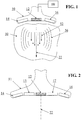
- FIG. 3 illustrates a multiple aperture elastography probe comprising a central init transducer array 12 and a pair of concave curved lateral imaging arrays 18, 20.
- multiple imaging apertures may be dynamically assigned on one or both of the concave lateral arrays 18, 20 as described in Applicants' prior US Patent Application No. 13/272,105 .
- each of the concave curved lateral arrays may be treated as a separate aperture.
- FIG. 3A illustrates a multiple aperture elastography probe comprising a single continuous concave curved transducer array 19.
- any portion of the continuous curved array 19 may be temporarily or permanently configured, designated, and controlled/operated as an init array.
- FIG. 3B illustrates a multiple aperture elastography probe comprising a 3D array 25 as described in Applicants' prior Application No. 13/272,105 .
- a group of transducer elements 12 is shown designated as a shear wave initiating region.
- any other region of the 3D array 25 may be designated as an init region.
- a probe with at least three arrays may be adapted for elastography by replacing at least one transducer array with a low frequency init transducer array.
- an init transducer array of a multiple aperture probe may be positioned between at least two other arrays.
- Such probe configurations may include adjustable probes, cardiac probes, universal probes, intravenous ultrasound (IVUS) probes, endo-vaginal probes, endo-rectal probes, transesophageal probes or other probes configured for a particular application.
- IVUS intravenous ultrasound
- any other multiple aperture or single-aperture ultrasound imaging probe may be adapted for use with the elastography systems and methods described herein.
- an init array may be provided on a separate probe entirely independent of an imaging probe.
- an init probe may be provided with a separate housing from the housing of the imaging probe.
- an independent init probe may be configured to be temporarily attached to an imaging probe.
- such a separate init probe may be controlled by the same ultrasound imaging system as an imaging probe, or the init probe may be controlled independently of the imaging system.
- An independently-controlled elastography init pulse controller may be synchronized with an ultrasound imaging system in order to provide the imaging system with accurate timing information indicating the time at which an init pulse is transmitted.
- similar frame rates may be achieved by transmitting a plane wave front (e.g., by transmitting simultaneous pulses from several transducers in a common array), receiving echoes, and mapping the received echoes to pixel locations using techniques similar to those described above.
- plane-wave transmitting systems may achieve frame rates similar to those achieved with ping-based imaging techniques.
- init array 12 may be configured to transmit shear-wave initiating ultrasound pulses with frequencies between about 1 MHz and about 10 MHz. Alternatively, the init array 12 may be configured to transmit shear-wave initiating ultrasound pulses with a frequency up to about 18 MHz or higher. In some arrangements, an ultrasound frequency for producing init pulses may be about half of an ultrasound frequency used for imaging. Depending on materials and construction, a single transducer array may be capable of producing both low frequency ultrasound pulses for an init pulse and relatively high frequency ultrasound pulses for imaging. However, in some arrangements it may be desirable to use transducers optimized for a relatively narrow frequency range to allow for more efficient control of an init pulse or an imaging pulse.
- an init transducer array 12 may comprise a separate array configured to function exclusively as an init array, such as by being optimized to function efficiently within an expected init frequency range.
- an init array may be structurally different than separate imaging arrays.
- an init array may be physically identical to an imaging array, and may differ only in terms of its operation and use.
- the init transducer array 12 may comprise a rectangular or otherwise shaped array (e.g., a 1D, 1.xD, 2D or other rectangular array) of piezoelectric elements. In other arrangements, the init transducer array 12 may comprise a rectangular or otherwise shaped array of capacitive micro-machined ultrasound transducer (CMUT) elements.
- CMUT capacitive micro-machined ultrasound transducer
- the init array 12 may comprise an annular array 30 as shown for example in FIG. 4 .
- An annular array may comprise a plurality of transducer elements arranged in concentric circular or elliptical patterns. Such annular arrays 20 may also use any suitable transducer material.
- an init array 12 may comprise a switched ring annular transducer array.
- a switched-ring annular array may include a dish-shaped ultrasonic transducer (e.g., a segment of a sphere) which may be divided into a plurality of concentric annular transducer elements of which the innermost element may be either a planar annulus or a complete dish.
- the curvature of the front surface of the annular array 20 and any lens or impedance matching layer between the transducer and the region of interest surface may at least partially determine the focal length of the transducer.
- an annular array may be substantially planar and an acoustic lens may be employed to focus the transmitted ultrasound energy.
- An annular array 20 may include any number of rings, such as three rings in addition to the center disc as shown in FIG. 4 .
- an annular array may include 2, 4, 5, 6. 7. 8, 9, 10 or more rings in addition to a center disc or dish.
- the rings may be further decoupled by etching, scribing, complete cutting or otherwise dividing the rings into a plurality of ring elements within each ring.
- an annular array transducer for operating to depths of 25 cm may have a diameter of 40 mm with the outer ring may have a width of approximately 1.85 mm, providing a surface area of 222 mm 2 ; the inner ring may have a width of approximately 0.8 mm and lying at an approximate radius of 10.6 mm to provide a surface area of 55 mm 2 .
- each ring (or each ring element within a ring) may have individual electrical connections such that each ring (or ring element) may be individually controlled as a separate transducer element by the control system such that the rings may be phased so as to direct a shear-wave initiating pulse to a desired depth within the region of interest.
- the amplitude of the energy applied may determine the amplitude of the emitted ultrasonic waves which travel away from the face of the annular array 20.
- the size and/or number of elements in an init array may be determined by the shape or other properties of the shear waves to be produced.
- a shear-wave initiating pulse produced by an init transducer array 12 may be focused during transmission to provide maximum power at the region of interest.
- the init pulse may be focused on an init line 22 (e.g., as shown in FIGs. 1, 2 and 3 ).
- the init pulse may further be focused at a desired depth to produce a maximum disruptive power at the desired depth.
- the axial focus line and the focused depth point may be determined by transmitting pulses from a plurality of transducer elements at a set of suitable delays (i.e., using "phased array” techniques).
- transmit delays may be omitted when using an annular array with a series of switched rings as discussed above.
- the init pulse need not be electronically steerable.
- the probe may be configured to always transmit an init pulse along a consistent line relative to the probe.
- the expected line of the init pulse may be displayed on the ultrasound display (e.g., overlaying a contemporaneous B-mode image of the region of interest) so as to provide an operator with a visual indication of the path of the init pulse relative to the imaged region of interest.
- a sonographer may manipulate the probe until the display shows a representative init line passing through an object to be evaluated by elastography.
- an init pulse may be electronically steered in a direction indicated by an operator.
- the line of the init pulse may be selected by an operator through any appropriate user interface interaction without the need to move the probe.
- the user interface interaction may include a visual display of the init line on a display screen (e.g., overlaying a contemporaneous B-mode image of the region of interest).
- a shear wave may be initiated in a region of interest 50 from an init pulse from a multiple aperture elastography probe 10 (or any other suitably configured elastography probe).
- the init pulse may be focused along a line 22 extending from the init transducer array 12 into the region of interest to at least a desired depth.
- the line 22 may be perpendicular to the init transducer array 12.
- An initial pulse 52 transmitted along the init line 22 will tend to induce a wave front 56 propagating outwards from the line 22 within the image plane.
- the propagating wavefront 56 induced by the init pulse will push the tissue in the direction of propagation.
- An elastic medium such as human tissue will react to this push by a restoring force which induces mechanical waves including shear waves which propagate transversely from the line 22 in the tissue.
- Embodiments of elastographic imaging processes will now be described with reference to the probe construction of FIG. 1 and the flow charts of FIGs. 5-7 . These processes may be used with any suitably configured probe as described above.
- the left and right lateral transducer arrays 14, 16 may be used to image the region of interest 50 with either, both or a combination of a high frame rate ultrasound imaging technique and a high resolution multiple aperture ultrasound imaging technique.
- high resolution imaging and “high frame rate imaging” are used herein as abbreviated names for alternative imaging processes. These terms are not intended to be limiting or exclusive, as the "high resolution imaging” process may also be operated at a high frame rate relative to other imaging techniques, and the “high frame rate imaging” process may also produce images of a substantially higher resolution than other imaging techniques. Furthermore, the rate of shear wave propagation may be detected using high frame rate imaging techniques and/or high resolution imaging techniques other than those described or referenced herein.
- FIG. 5 illustrates an embodiment of a high resolution multiple aperture imaging process 60 that may use a multiple aperture ultrasound imaging probe such as that shown in FIG. 1 .
- one or both of the imaging arrays 14, 16 may include one or more transducer elements temporarily or permanently designated as transmit elements T1 through Tn. The remaining transducer elements of one or both of the imaging arrays 14, 16 may be designated as receive elements.
- a high resolution multiple aperture ultrasound imaging process 60 may comprise transmitting a series of successive pulses from a series of different transmit apertures (T1 ... Tn) 62, receiving echoes 64 from each pulse with a plurality of elements on a receive aperture, and obtaining a complete image 66 from echoes received from each transmit pulse. These images may then be combined 68 into a final high-resolution image.
- Embodiments of such a high resolution multiple aperture imaging process may be substantially similar to the process shown and described in Applicants' prior US Patent Application No. 13/029,907 referenced above.
- the steps of transmitting an ultrasound signal 62A, receiving echoes 64A, and forming an image 66A may be performed using a first transmit transducer T1.
- signals may be transmitted 62B from a different transmit transducer Ti, echoes may be received 64B, and a second image may be formed 66B.
- the process of steps 62x-66x may be repeated using n different transmit transducers which may respectively be located at any desired position within an ultrasound probe.
- a desired number of image also referred to as image layers
- image layers may be combined 68 into a single image frame, thereby improving image quality.
- the process 60 may then be repeated to obtain multiple time-domain frames which may then be consecutively displayed to a user.
- FIG. 6 illustrates an embodiment of a high frame rate imaging process 70.
- a high frame rate ultrasound imaging process 70 may comprise transmitting successive pings from a single transmit aperture Tx 72, forming a complete image 76 from echoes received 74 from each transmitted ping 72, and treating each image 76 as a successive time domain frame. In this way, slight changes in the position of reflectors in the region of interest 50 can be sampled at a very high frame rate.
- a ping may be transmitted from a chosen transmit transducer Tx 72A, echoes may be received 74A and a first frame may be formed 76A.
- the same cycle of steps transmitting 72B and receiving 74B may then be repeated to produce a second frame 76B, a third frame (steps 72C, 74C, 76C), and as many subsequent frames as desired or needed as described elsewhere herein.
- a maximum frame rate of an imaging system using ping-based imaging techniques may be reached when a ping repetition frequency (i.e., the frequency at which successive pings are transmitted) is equal to an inverse of the round trip travel time (i.e., the time for an ultrasound wave to travel from a transmit transducer to a reflector at a desired distance from the transducer, plus the time for an echo to return from the reflector to a receive transducer along the same or a different path).
- overlapping pings may be used with coded excitation or other methods of distinguishing overlapping echoes. That is, a second ping may be transmitted before all echoes from a first ping are received.
- the transmitted ping signals may be coded or otherwise distinguished such that echoes of a first ping may be recognized as distinct from echoes of a second ping.
- coded excitation techniques are known to those skilled in the art, any of which may be used with a point-source multiple aperture imaging probe.
- overlapping pings may also be distinguished by transmitting pings at different frequencies or using any other suitable techniques. Using overlapping pings, even higher imaging frame rates may be achieved.
- an imaging window may be defined during a B-mode imaging process.
- the defined image window may be a section of the region of interest in which elastography is to be performed.
- the image window may be defined after any combination of probe positioning, depth-selection, zooming, panning, etc.
- an image window may be as large as an entire insonified region of interest.
- an image window may be only a smaller section of the complete region of interest (e.g., a "zoomed-in" section).
- an image window may be defined after an imaging session using echo data retrieved from a raw data memory device.
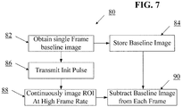
- FIG. 7 illustrates an embodiment of an elastography process 80 using a probe such as that shown in FIG. 1 .
- an elastography process 80 may generally involve the steps of obtaining 82 and storing 84 a baseline image, transmitting a shear-wave initiating pulse (an init pulse) 86 into the region of interest 50, imaging the region of interest 50 using a high frame rate imaging process 88, and subtracting the baseline image 90 from each frame obtained during the high frame rate imaging process 88.
- the remaining series of "difference frames" can then be analyzed to obtain information about the tissue displaced by the shear wave 56 propagating through the tissue of the region of interest 50.
- the propagation speed of the shear wave 56 may be obtained through analysis of the perturbation of tissue in the time-series of difference frames.
- an init line 22 may be displayed on an ultrasound image display screen overlying an image of the target region.
- the ultrasound imaging system may continuously image the region of interest with a high resolution imaging process as discussed above with reference to FIG. 5 .
- any other desired ultrasound imaging process may be used to obtain an image of the region to be analyzed by an elastography process.
- an elastography depth may be selected, and an elastography process 80 may be initiated.
- an elastography depth may be selected by an operator via a suitable user interface action.
- an elastography depth may be selected automatically by an ultrasound imaging control system.
- an elastography process may be initiated manually by an operator of the ultrasound system.
- an elastography process 80 may be initiated automatically by an ultrasound system upon automatic identification of a structure to be inspected.
- an elastography process 80 using a probe such as that shown in FIG. 1 may begin by obtaining 82 and storing 84 a baseline image of the target region of interest 50.
- the baseline image may be formed by obtaining a single frame using a high-frame-rate imaging process such as that described above.
- a baseline image may be formed by transmitting an imaging pulse from a single transducer element Tx from a first of the lateral transducer arrays 14, 16 (e.g., the right array 16), and receiving echoes on multiple elements of the second of the lateral transducer arrays 14, 16 (e.g., the left array 14).
- echoes from the transmit pulse may also be received by receive elements on the first transducer array (e.g. the right array 16).
- the baseline image may then be formed and stored 84 for use in subsequent steps.
- the baseline image may be obtained 82 using a high resolution imaging process such as that described above.
- the init transducer array may be operated to transmit a shear-wave initiating pulse 86 into the region of interest.
- An init pulse may be produced by any suitable devices and methods as described above.
- the shear wave initiating pulse may be focused along a displayed init line 22, and may be focused at a particular depth within the region of interest.
- the system may begin imaging the region of interest at a high frame rate 88 using the lateral imaging arrays 14, 16.
- the high frame rate imaging process may comprise the process described above with reference to FIG. 6 .
- the high frame rate imaging process may comprise transmitting a series of transmit pulses from a single transmit aperture Tx, and receiving echoes at a plurality of elements on at least one receive aperture.
- the high frame rate imaging 88 may be performed by transmitting ultrasound pulses from the same transmit element (or aperture) as that used in the step of obtaining a baseline image 82.
- the high frame rate imaging may continue at least until propagation of the induced shear wave has stopped or has progressed to a desired degree.
- a duration of high frame-rate imaging time may be calculated in advance based on an expected minimum propagation speed and an image size.
- the high frame rate imaging 88 may be stopped upon detecting the shear wave's propagation at an extent of an imaging frame.
- forming a single frame during a high frame rate imaging process 88 may include combining image layers obtained from echoes received at different receiving transducer elements. For example, separate images may be formed from echoes received by each individual transducer element of a receive aperture to form a single improved image. Then, a first image produced by echoes received by all elements of a first receive aperture may be combined with a second image produced by echoes received by all elements of a second receive aperture in order to further improve the quality of the resulting image. In some embodiments, the image resulting from such combinations may then be used as a single frame in the high frame rate imaging process 88. Further examples of such image combining are described in US Patent Application No. 13/029,907 referenced above.
- the baseline image may then be subtracted 90 from each individual frame obtained in the high frame rate imaging process 88.
- each pixel value of a single frame may be subtracted from the value of each corresponding pixel in the baseline image.
- the image resulting from such subtraction may be referred to as a "difference image” or a "difference frame.”
- the difference images thus obtained will include pixel values representing substantially only the shear waveform plus any noise.
- the steps of obtaining a baseline image 82, transmitting an init pulse 86 continuously imaging at a high frame rate 88, and obtaining difference image frames 90 may be repeated as many times as desired.
- the difference images from such multiple cycles may be averaged or otherwise combined in order to improve a signal to noise level.
- the propagating shear waveform may be detected along lines transverse to the direction of the init pulse (e.g., as shown in FIG. 1 ) by detecting perturbation (i.e., small changes in an otherwise 'normal' pattern) in subsequent difference frames.
- the speed of the shear wave's propagation may be obtained by determining the position of the shear wave in multiple image frames obtained at known time intervals.
- the perturbation caused by a propagating shear wave may produce a relatively disbursed image of the propagating wave front.
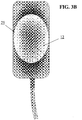
- perturbation may appear in a difference frame as a speckle pattern 92 such as that shown in FIG. 8 .
- An approximate center line 94 of the point cloud 92 may be determined and treated as representative of the position of the propagating shear wavefront.
- a line, curve or other path 94 may be fit to the point cloud 92 using any suitable path fit algorithm.
- an absolute value of the difference frame may be calculated, and a local position of the shear wave may be determined by averaging the position of the nearest x points.
- the analysis may be limited to only a portion of the point cloud 92 (and/or a corresponding center line 94). For example, if it is determined (by visual inspection or by automated analysis) that a small segment of the shear wavefront is propagating faster than adjacent segments, the region(s) of apparent higher or lower propagation speed may be selected, and the speed of propagation may be calculated for only that portion of the shear wavefront.
- an approximate position of the shear wave in the given difference frame may be calculated.
- the rate of propagation of the wavefront between any two frames may be determined by dividing the distance traveled by the shear wave by the time that elapsed between obtaining the two frames.
- the position of a shear wave in any given frame may be measured relative to any other suitable datum.
- the number of frames needed to measure the propagation speed of a shear wave may vary. In some embodiments an approximate speed measurement may be obtained from as few as two or three frames obtained at known time intervals. In other embodiments, at least ten frames obtained at known time intervals may be needed to obtain a sufficiently accurate time measurement. In further embodiments, at least 100 frames obtained at known time intervals may be used to obtain a more accurate time measurement. In still further embodiments, 200 frame or more may be used. Generally, the accuracy of shear wave propagation speed measurements may increase with the number of frames from which such measurements are made. As the number of frames increases, so does computational complexity, so the number of frames to be used may be balanced with available processing capabilities.
- any number of algorithms may be used.
- the shear wave position may be detected in each available frame, a speed may be calculated between each consecutive pair of frames, and the results of all such speed measurements may be averaged to obtain a single speed value.
- speed measurements may be calculated based on time intervals and relative shear wave positions between different and/or variable numbers of frames. For example, propagation speed may be calculated between every three frames, every five frames, every 10 frames, every 50 frames, etc. Such measurements may then be averaged with one another and/or with measurements obtained from consecutive frame pairs. Weighted averages may also be used in some embodiments.
- an entire elastography process 80 ( FIG. 7 ) may be repeated at different focus depths relative to the init transducer array 12.
- un-beamformed elastography echo data obtained at various depths may be stored and combined into a single 2D or 3D data set for further post processing and/or for later viewing and analysis.
- un-beamformed elastography echo data may be captured and stored for later processing on the imaging system or any other suitable computing hardware.
- the propagation speed of a shear wave may be measured by detecting the speed of moving/displaced tissues using the multiple aperture Doppler techniques described in Applicant's co-pending US Patent Application No. 13/690,989, filed November 30, 2012 , titled "Motion Detection Using Ping-Based And Multiple Aperture Doppler Ultrasound.”
- ⁇ is the density of tissue expressed in kg/m 3 . Because the density of tissues tends to vary minimally, an approximate density value may be assumed for the purpose of calculating elasticity using a measured propagation speed value. The fact that the speed term is squared further minimizes the effect of any error in the assumed density value. Thus, the elasticity of the tissue may be calculated after measuring only the shear wave propagation velocity c and using an assumed approximate value for tissue density.
- the density value may be stored in a digital memory device within or electronically accessible by the controller. In other embodiments, the density value may be manually entered or edited by a user via any suitable user interface device. Once the speed of shear wave propagation has been measured for a desired area within the region of interest, the controller may retrieve the density value and calculate the elasticity for the desired area.
- elasticity estimates may be overlaid on an image of the region of interest.
- such an overlay may be provided as a color coded shaded image, showing areas of high elasticity in contrasting colors to areas of relatively low elasticity.
- a propagating shear wave may be displayed on an image.
- a propagating shear wave may be displayed as an animated moving line, as changing colors, as a moving point cloud or in other ways.
- a numeric value of a shear wave propagation speed may be displayed.
- numeric values of elasticity may be displayed on an image of the region of interest. Soft tissues will tend to have relatively small values of elasticity, and liquid-filled areas do not conduct shear waves at all.
- an ultrasound imaging system configured to store digitized echo waveforms during an imaging session.
- Such digital echo data may be subsequently processed on an imaging system or on an independent computer or other workstation configured to beamform and process the echo data to form images.
- a workstation device may comprise any digital processing system with software for dynamically beamforming and processing echo data using any of the techniques described above.
- processing may be performed using data processing hardware that is entirely independent of an ultrasound imaging system used to transmit and receive ultrasound signals.
- Such alternative processing hardware may comprise a desktop computer, a tablet computer, a laptop computer, a smartphone, a server or any other general purpose data processing hardware.
- received echo data may be stored at various stages from pure analog echo signals to fully processed digital images or even digital video.
- a purely raw analog signal may be stored using an analog recording medium such as analog magnetic tape.
- digital data may be stored immediately after passing the analog signal through an analog-to-digital converter. Further processing, such as band-pass filtering, interpolation, down-sampling, up-sampling, other filtering, etc. may be performed on the digitized echo data, and raw data may be stored after such additional filtering or processing steps. Such raw data may then be beamformed to determine a pixel location for each received echo, thereby forming an image.
- raw echo data may refer to stored echo information describing received ultrasound echoes (RX data) at any level of processing prior to beamforming.
- Raw echo data may include echo data resulting from B-mode pings, Doppler pings, or any other ultrasound transmit signal.
- TX data Transmit data
- TX data may also include information defining a line along which a shear-wave initiating pulse is transmitted, and timing information indicating a time at which such a shear-wave initiating pulse is transmitted relative to received echo data.
- TX data may be stored explicitly in the same raw data memory device in which raw echo data is stored.
- TX data describing a transmitted signal may be stored as a header before or as a footer after a set of raw echo data generated by the transmitted signal.
- TX data may be stored explicitly in a separate memory device that is also accessible to a system performing a beamforming process.
- transmit data is stored explicitly
- the phrases "raw echo data” or "raw data” may also include such explicitly stored TX data.
- transducer element position information may be explicitly stored in the same or a separate memory device. Such element position data may be referred to as “calibration data” or “element position data”, and in some embodiments may be generally included within "raw data.”
- TX data may also be stored implicitly. For example, if an imaging system is configured to transmit consistently defined ultrasound signals (e.g., consistent magnitude, shape, frequency, duration, etc.) in a consistent or known sequence, then such information may be assumed during a beamforming process. In such cases, the only information that needs to be associated with the echo data is the position (or identity) of the transmit transducer(s). In some embodiments, such information may be implicitly obtained based on the organization of raw echo data in a raw data memory. For example, a system may be configured to store a fixed number of echo records following each ping.
- consistently defined ultrasound signals e.g., consistent magnitude, shape, frequency, duration, etc.
- echoes from a first ping may be stored at memory positions 0 through 'n' (where 'n' is the number of records stored for each ping), and echoes from a second ping may be stored at memory positions n+1 through 2n+1.
- one or more empty records may be left in between echo sets.
- received echo data may be stored using various memory interleaving techniques to imply a relationship between a transmitted ping and a received echo data point (or a group of echoes). Similarly, assuming data is sampled at a consistent, known sampling rate, the time at which each echo data point was received may be inferred from the position of that data point in memory. In some embodiments, the same techniques may also be used to implicitly store data from multiple receive channels in a single raw data memory device.
- raw TX data and raw echo data may be captured and stored during an imaging session in which an elastography process is performed. Such data may then be later retrieved from the memory device, and beamforming, image processing, and shear-wave speed measurement steps may be repeated using different assumptions, inputs or algorithms in order to further improve results. For example, during such re-processing of stored data, assumed values of tissue density or speed-of-sound may be used. Beamforming, image layer combining, or speed measurement averaging algorithms may also be modified during such re-processing relative to a real-time imaging session. In some embodiments, while reprocessing stored data, assumed constants and algorithms may be modified iteratively in order to identify an optimum set of parameters for a particular set of echo data.
Landscapes
- Engineering & Computer Science (AREA)
- Physics & Mathematics (AREA)
- Radar, Positioning & Navigation (AREA)
- Remote Sensing (AREA)
- Health & Medical Sciences (AREA)
- Life Sciences & Earth Sciences (AREA)
- Acoustics & Sound (AREA)
- General Physics & Mathematics (AREA)
- Computer Networks & Wireless Communication (AREA)
- Radiology & Medical Imaging (AREA)
- Molecular Biology (AREA)
- Pathology (AREA)
- Biophysics (AREA)
- Biomedical Technology (AREA)
- Heart & Thoracic Surgery (AREA)
- Medical Informatics (AREA)
- Nuclear Medicine, Radiotherapy & Molecular Imaging (AREA)
- Surgery (AREA)
- Animal Behavior & Ethology (AREA)
- General Health & Medical Sciences (AREA)
- Public Health (AREA)
- Veterinary Medicine (AREA)
- Gynecology & Obstetrics (AREA)
- Computer Vision & Pattern Recognition (AREA)
- Ultra Sonic Daignosis Equipment (AREA)
Applications Claiming Priority (2)
| Application Number | Priority Date | Filing Date | Title |
|---|---|---|---|
| US201261601482P | 2012-02-21 | 2012-02-21 | |
| PCT/US2013/027120 WO2013126559A1 (en) | 2012-02-21 | 2013-02-21 | Determining material stiffness using multiple aperture ultrasound |
Publications (3)
| Publication Number | Publication Date |
|---|---|
| EP2816958A1 EP2816958A1 (en) | 2014-12-31 |
| EP2816958A4 EP2816958A4 (en) | 2016-02-17 |
| EP2816958B1 true EP2816958B1 (en) | 2020-03-25 |
Family
ID=48982792
Family Applications (1)
| Application Number | Title | Priority Date | Filing Date |
|---|---|---|---|
| EP13751662.1A Active EP2816958B1 (en) | 2012-02-21 | 2013-02-21 | Determining material stiffness using multiple aperture ultrasound |
Country Status (7)
| Country | Link |
|---|---|
| US (3) | US9339256B2 (zh) |
| EP (1) | EP2816958B1 (zh) |
| JP (1) | JP6438769B2 (zh) |
| KR (1) | KR102134763B1 (zh) |
| CN (2) | CN107028623B (zh) |
| HK (1) | HK1202038A1 (zh) |
| WO (1) | WO2013126559A1 (zh) |
Families Citing this family (54)
| Publication number | Priority date | Publication date | Assignee | Title |
|---|---|---|---|---|
| WO2008051639A2 (en) | 2006-10-25 | 2008-05-02 | Maui Imaging, Inc. | Method and apparatus to produce ultrasonic images using multiple apertures |
| US9282945B2 (en) * | 2009-04-14 | 2016-03-15 | Maui Imaging, Inc. | Calibration of ultrasound probes |
| EP2536339B1 (en) | 2010-02-18 | 2024-05-15 | Maui Imaging, Inc. | Point source transmission and speed-of-sound correction using multi-aperture ultrasound imaging |
| WO2012051308A2 (en) | 2010-10-13 | 2012-04-19 | Maui Imaging, Inc. | Concave ultrasound transducers and 3d arrays |
| BR112013021791B1 (pt) * | 2011-02-25 | 2020-11-17 | Mayo Foundation For Medical Education Ano Research | método para medir uma propriedade mecânica de um paciente com um sistema de ultrassom |
| KR20140107648A (ko) | 2011-12-29 | 2014-09-04 | 마우이 이미징, 인코포레이티드 | 임의의 경로들의 m-모드 초음파 이미징 |
| CN107028623B (zh) | 2012-02-21 | 2020-09-01 | 毛伊图像公司 | 使用多孔超声确定材料刚度 |
| WO2013148673A1 (en) | 2012-03-26 | 2013-10-03 | Maui Imaging, Inc. | Systems and methods for improving ultrasound image quality by applying weighting factors |
| US9211111B2 (en) * | 2012-04-05 | 2015-12-15 | Hitachi Aloka Medical, Ltd. | Determination of shear wave characteristics |
| IN2015DN00556A (zh) * | 2012-08-10 | 2015-06-26 | Maui Imaging Inc | |
| US9986969B2 (en) | 2012-08-21 | 2018-06-05 | Maui Imaging, Inc. | Ultrasound imaging system memory architecture |
| WO2014133360A1 (ko) | 2013-02-28 | 2014-09-04 | 삼성메디슨 주식회사 | 초음파 진단 장치 및 그 방법 |
| WO2014160291A1 (en) | 2013-03-13 | 2014-10-02 | Maui Imaging, Inc. | Alignment of ultrasound transducer arrays and multiple aperture probe assembly |
| WO2015023081A1 (ko) * | 2013-08-12 | 2015-02-19 | 삼성전자 주식회사 | 탄성 영상을 생성하는 방법 및 초음파 진단 장치 |
| US9883848B2 (en) | 2013-09-13 | 2018-02-06 | Maui Imaging, Inc. | Ultrasound imaging using apparent point-source transmit transducer |
| CN104622507B (zh) * | 2013-11-11 | 2017-08-18 | 中国科学院深圳先进技术研究院 | 弹性模量测量方法和系统 |
| KR101654674B1 (ko) * | 2013-11-28 | 2016-09-06 | 삼성전자주식회사 | 탄성 영상 제공 방법 및 이를 위한 초음파 장치 |
| KR101649272B1 (ko) * | 2014-01-06 | 2016-08-18 | 삼성전자주식회사 | 초음파 진단 장치, 초음파 영상 촬영 방법, 프로브 및 컴퓨터 판독가능 기록매체 |
| WO2015102474A1 (en) * | 2014-01-06 | 2015-07-09 | Samsung Electronics Co., Ltd. | Ultrasound diagnostic apparatus, ultrasound image capturing method, and computer-readable recording medium |
| US20150374334A1 (en) * | 2014-01-08 | 2015-12-31 | QT Ultrasound LLC | Quantitative transmission ultrasound imaging of dense anatomical structures |
| FR3017041B1 (fr) * | 2014-01-31 | 2016-03-04 | Centre Nat Rech Scient | Procede et dispositif ultrasonore de caracterisation des milieux mous anisotropes, et ensemble de sonde ultrasonore pour un tel dispositif de caracterisation |
| US20150272547A1 (en) * | 2014-03-31 | 2015-10-01 | Siemens Medical Solutions Usa, Inc. | Acquisition control for elasticity ultrasound imaging |
| KR102430449B1 (ko) | 2014-08-18 | 2022-08-05 | 마우이 이미징, 인코포레이티드 | 네트워크-기반 초음파 이미징 시스템 |
| US10292682B2 (en) * | 2014-09-29 | 2019-05-21 | Samsung Electronics Co., Ltd. | Method and medical imaging apparatus for generating elastic image by using curved array probe |
| KR101649273B1 (ko) | 2014-09-29 | 2016-08-18 | 삼성전자주식회사 | 곡면 프로브를 이용하여 탄성 영상을 생성하는 방법 및 그 의료 영상 장치 |
| EP3231369A1 (en) * | 2014-12-08 | 2017-10-18 | Hitachi, Ltd. | Ultrasound diagnostic device and elasticity evaluation method |
| KR20180094774A (ko) * | 2015-03-18 | 2018-08-24 | 디시전 사이선씨즈 메디컬 컴패니, 엘엘씨 | 합성 개구 초음파 시스템 |
| JP6360262B2 (ja) * | 2015-03-31 | 2018-07-18 | コーニンクレッカ フィリップス エヌ ヴェKoninklijke Philips N.V. | 超音波弾性に基づく病変境界マッピングの較正 |
| KR102035993B1 (ko) | 2015-09-03 | 2019-10-25 | 지멘스 메디컬 솔루션즈 유에스에이, 인크. | 탄성 영상을 형성하는 초음파 시스템 및 방법 |
| CN113812979A (zh) * | 2015-10-08 | 2021-12-21 | 梅约医学教育与研究基金会 | 用于利用持续换能器振动进行超声弹性成像的系统和方法 |
| CN113729764A (zh) | 2016-01-27 | 2021-12-03 | 毛伊图像公司 | 具有稀疏阵列探测器的超声成像 |
| WO2017160783A1 (en) * | 2016-03-14 | 2017-09-21 | Mayo Foundation For Medical Education And Research | Shear wave group velocity estimation using spatiotemporal peaks and amplitude thresholding |
| US10376233B2 (en) * | 2016-04-08 | 2019-08-13 | Siemens Medical Solutions Usa, Inc. | Diffraction source compensation in medical diagnostic ultrasound viscoelastic imaging |
| US11413007B2 (en) | 2016-05-26 | 2022-08-16 | University Of Washington | Non-contact acoustic radiation force based (ARF-based) generation of broad bandwidth mechanical waves using air-coupled ultrasound |
| EP3475992A4 (en) * | 2016-06-22 | 2020-02-19 | Duke University | ULTRASONIC TRANSDUCERS FOR CONSTRUCTIVE SHEAR WAVE INTERFERENCE AND RELATED METHODS AND SYSTEMS |
| US10912536B2 (en) * | 2016-08-23 | 2021-02-09 | Carestream Health, Inc. | Ultrasound system and method |
| CN106510766A (zh) * | 2016-12-14 | 2017-03-22 | 苏州大学 | 基于剪切波传播的软骨组织弹性测量装置及其方法 |
| CN108451499B (zh) * | 2017-02-21 | 2021-03-16 | 通用电气公司 | 弹性成像系统,及其方法和震动单元 |
| US11357478B2 (en) | 2017-04-11 | 2022-06-14 | Massachusetts Institute Of Technology | Methods and systems for shear wave elastography |
| WO2019006243A1 (en) * | 2017-06-30 | 2019-01-03 | Butterfly Network, Inc. | ELASTICITY IMAGING IN ULTRASONIC FOCUSES OF HIGH INTENSITY |
| CN107643096A (zh) * | 2017-07-24 | 2018-01-30 | 成都东易盛泰科技有限公司 | 一种混凝土空洞监测记录仪 |
| CN114848011A (zh) | 2018-04-13 | 2022-08-05 | 深圳迈瑞生物医疗电子股份有限公司 | 超声成像方法及超声成像设备 |
| CN116869567A (zh) * | 2018-05-15 | 2023-10-13 | 深圳迈瑞生物医疗电子股份有限公司 | 一种剪切波弹性测量方法及剪切波弹性成像系统 |
| CN112638274A (zh) * | 2018-08-29 | 2021-04-09 | 皇家飞利浦有限公司 | 用于智能剪切波弹性成像的超声系统和方法 |
| CN109492277B (zh) * | 2018-10-25 | 2022-06-21 | 哈尔滨工程大学 | 一种估算金属增材制造超声冲击处理作用层深度的方法 |
| KR102141654B1 (ko) * | 2018-11-28 | 2020-08-05 | 재단법인 대구경북첨단의료산업진흥재단 | 송수신 듀얼 모드 집속 초음파 트랜스듀서 및 이를 이용한 미소기포 캐비테이션 이미지 가시화방법 |
| EP3693756A1 (en) | 2019-02-07 | 2020-08-12 | SuperSonic Imagine | An ultrasound system |
| US11452504B2 (en) * | 2019-04-02 | 2022-09-27 | Shenzhen Mindray Bio-Medical Electronics Co., Ltd. | Regional contrast enhancement based on complementary information to reflectivity information |
| JP7354632B2 (ja) * | 2019-07-12 | 2023-10-03 | コニカミノルタ株式会社 | 超音波診断装置、および、超音波診断装置の制御方法 |
| WO2021058732A1 (en) * | 2019-09-25 | 2021-04-01 | Institut National De La Sante Et De La Recherche Medicale (Inserm) | A method for measuring the speed of sound in liver with a moving probe and associated methods and devices |
| EP4034848A1 (en) * | 2019-09-25 | 2022-08-03 | Institut National De La Sante Et De La Recherche Medicale - Inserm | A method for measuring the speed of sound in liver with a specific probe and associated methods and devices |
| CN110720948B (zh) * | 2019-11-12 | 2021-02-02 | 无锡海斯凯尔医学技术有限公司 | 基于超声检测系统的生物体征检测方法 |
| WO2022197918A1 (en) * | 2021-03-18 | 2022-09-22 | University Of Southern California | Non-contact ultrasound viscoelastic spectroscopy |
| KR102535534B1 (ko) * | 2022-10-07 | 2023-05-26 | 주식회사 엠아이티 | 초음파 검사 장치 및 이를 이용한 초음파 검사 방법 |
Citations (1)
| Publication number | Priority date | Publication date | Assignee | Title |
|---|---|---|---|---|
| US4694434A (en) * | 1984-06-12 | 1987-09-15 | Von Ramm Olaf T | Three-dimensional imaging system |
Family Cites Families (633)
| Publication number | Priority date | Publication date | Assignee | Title |
|---|---|---|---|---|
| US3174286A (en) | 1963-06-27 | 1965-03-23 | Gen Motors Corp | Master cylinder |
| JPS4911189A (zh) | 1972-05-29 | 1974-01-31 | ||
| US3895381A (en) | 1973-02-21 | 1975-07-15 | Winston E Kock | Synthetic aperture imaging systems |
| AT343265B (de) | 1973-08-16 | 1978-05-26 | Siemens Ag | Gerat fur die messung der geschwindigkeit von insbesondere in leitungen stromenden medien |
| US4072922A (en) | 1975-11-13 | 1978-02-07 | Seiscom Delta Inc. | Method for seismic exploration for enhanced results in simulated cylindrical or plane waves |
| US4105018A (en) | 1976-02-02 | 1978-08-08 | University Of Utah | Acoustic examination, material characterization and imaging of the internal structure of a body by measurement of the time-of-flight of acoustic energy therethrough |
| US4097835A (en) | 1976-09-20 | 1978-06-27 | Sri International | Dual transducer arrangement for ultrasonic imaging system |
| US4055988A (en) | 1976-12-09 | 1977-11-01 | J. B. Engineering And Sales Company, Inc. | Alignment control apparatus for a turntable used in an ultrasonic testing system |
| JPS5444375A (en) | 1977-09-14 | 1979-04-07 | Oki Electric Ind Co Ltd | Ultrasonic wave reflection system |
| US4229798A (en) | 1978-01-30 | 1980-10-21 | Alistair Francis McDermott | Liquid storage tank contents gauge |
| US4333474A (en) | 1978-02-06 | 1982-06-08 | New York Institute Of Technology | Ultrasonic imaging system |
| US4271842A (en) | 1978-03-03 | 1981-06-09 | Smith Kline Instruments, Inc. | Apparatus and method for providing multiple ultrasonic sector image displays |
| US4180792A (en) | 1978-03-09 | 1979-12-25 | General Electric Company | Transmit-receive transducer array and ultrasonic imaging system |
| US4205394A (en) | 1978-11-03 | 1980-05-27 | The United States Of America As Represented By The Secretary Of The Navy | Sealed cavity hydrophone array calibration |
| JPS55103839A (en) | 1979-02-03 | 1980-08-08 | Fujitsu Ltd | Ultrasonic diagnosis apparatus |
| CA1137210A (en) | 1979-04-26 | 1982-12-07 | Francis S. Foster | Ultrasonic imaging method and device using one transducer having a line focus aligned with another transducer |
| US4259733A (en) | 1979-05-14 | 1981-03-31 | Seiscom Delta, Inc. | Multi-dimensional seismic imaging |
| US4265126A (en) | 1979-06-15 | 1981-05-05 | General Electric Company | Measurement of true blood velocity by an ultrasound system |
| US4327738A (en) | 1979-10-19 | 1982-05-04 | Green Philip S | Endoscopic method & apparatus including ultrasonic B-scan imaging |
| JPS56103327A (en) | 1980-01-21 | 1981-08-18 | Hitachi Ltd | Ultrasonic image pickup apparatus |
| US4325257A (en) | 1980-02-20 | 1982-04-20 | Kino Gordon S | Real-time digital, synthetic-focus, acoustic imaging system |
| JPS5731848A (en) | 1980-08-01 | 1982-02-20 | Fujitsu Ltd | Ultrasonic diagnostic device |
| JPS5849137A (ja) | 1981-09-18 | 1983-03-23 | 株式会社東芝 | 超音波血流測定装置 |
| US6324453B1 (en) | 1998-12-31 | 2001-11-27 | Automotive Technologies International, Inc. | Methods for determining the identification and position of and monitoring objects in a vehicle |
| JPS58223059A (ja) | 1982-06-21 | 1983-12-24 | Toshiba Corp | 超音波探傷装置 |
| US4452084A (en) | 1982-10-25 | 1984-06-05 | Sri International | Inherent delay line ultrasonic transducer and systems |
| JPS59101143A (ja) | 1982-12-02 | 1984-06-11 | 富士通株式会社 | 超音波による測定または加作用装置 |
| JPH064074B2 (ja) | 1983-02-14 | 1994-01-19 | 株式会社日立製作所 | 超音波診断装置およびこれを用いる音速計測方法 |
| JPS59174151A (ja) | 1983-03-25 | 1984-10-02 | 横河メディカルシステム株式会社 | 超音波映像装置 |
| US5141738A (en) | 1983-04-15 | 1992-08-25 | Schering Aktiengesellschaft | Ultrasonic contrast medium comprising gas bubbles and solid lipophilic surfactant-containing microparticles and use thereof |
| JPS6013109U (ja) | 1983-07-07 | 1985-01-29 | アロカ株式会社 | 超音波診断装置 |
| US4604697A (en) | 1983-08-05 | 1986-08-05 | Interspec, Inc. | Body imaging using vectorial addition of acoustic reflection to achieve effect of scanning beam continuously focused in range |
| JPS6068836A (ja) | 1983-09-24 | 1985-04-19 | 株式会社島津製作所 | 超音波診断装置 |
| US4539847A (en) | 1984-01-03 | 1985-09-10 | Texaco Inc. | Acoustic method and apparatus for measuring thickness of a coating layer on a substrate |
| JPS60150735A (ja) | 1984-01-18 | 1985-08-08 | 株式会社東芝 | 超音波診断装置 |
| US4662222A (en) | 1984-12-21 | 1987-05-05 | Johnson Steven A | Apparatus and method for acoustic imaging using inverse scattering techniques |
| US4781199A (en) | 1985-01-07 | 1988-11-01 | Kabushiki Kaisha Toshiba | System and method for measuring sound velocity of internal tissue in an object being investigated |
| JPS61203949A (ja) | 1985-03-04 | 1986-09-09 | 株式会社東芝 | 超音波診断装置 |
| US4669482A (en) | 1985-10-28 | 1987-06-02 | Board Of Regents, The University Of Texas System | Pulse echo method and apparatus for sound velocity estimation in vivo |
| US4817434A (en) | 1985-11-19 | 1989-04-04 | Forrest Anderson | Device for imaging three dimensions using simultaneous multiple beam formation |
| US4831601A (en) | 1986-10-31 | 1989-05-16 | Siemens Aktiengesellschaft | Apparatus for transmitting and receiving ultrasonic signals |
| FR2607631B1 (fr) | 1986-11-28 | 1989-02-17 | Thomson Cgr | Sonde pour appareil a ultrasons munie d'un arrangement concave d'elements piezo-electriques |
| JP2619446B2 (ja) | 1987-12-21 | 1997-06-11 | 株式会社日立製作所 | 超音波診断装置 |
| US4893628A (en) | 1988-04-04 | 1990-01-16 | Bjorn Angelsen | Dual element ultrasonic transducer probe for combined imaging of tissue structures and blood flow in real time |
| US4893284A (en) | 1988-05-27 | 1990-01-09 | General Electric Company | Calibration of phased array ultrasound probe |
| US5197475A (en) | 1988-08-10 | 1993-03-30 | The Board Of Regents, The University Of Texas System | Method and apparatus for analyzing material properties using ultrasound |
| US4990462A (en) | 1989-04-12 | 1991-02-05 | Advanced Micro Devices, Inc. | Method for coplanar integration of semiconductor ic devices |
| JP2777197B2 (ja) | 1989-06-13 | 1998-07-16 | 株式会社東芝 | 超音波診断装置 |
| JPH03126443A (ja) * | 1989-10-11 | 1991-05-29 | Matsushita Electric Ind Co Ltd | 超音波探触子 |
| US5050588A (en) | 1990-02-08 | 1991-09-24 | Richard Grey | High energy ultrasonic lens assembly with mounting facets |
| JP2849159B2 (ja) * | 1990-05-11 | 1999-01-20 | 淑 中山 | 超音波診断装置 |
| JPH0467856A (ja) | 1990-07-09 | 1992-03-03 | Yokogawa Medical Syst Ltd | バイスタティック送受信による超音波イメージャー |
| JP3015527B2 (ja) | 1991-08-14 | 2000-03-06 | 株式会社東芝 | 超音波診断装置 |
| JPH0467856U (zh) | 1990-10-25 | 1992-06-16 | ||
| US5062295A (en) | 1990-12-24 | 1991-11-05 | Sparktech | Dual tube sonic level gage |
| US5161536A (en) | 1991-03-22 | 1992-11-10 | Catheter Technology | Ultrasonic position indicating apparatus and methods |
| US5191890A (en) | 1991-04-22 | 1993-03-09 | Interspec, Inc. | Ultrasonic probe assembly |
| US5230339A (en) | 1991-06-13 | 1993-07-27 | Array Tech, Inc. | Performance evaluation of ultrasonic examination equipment |
| US5442462A (en) | 1992-06-10 | 1995-08-15 | D.V.P. Technologies Ltd. | Apparatus and method for smoothing images |
| US5349960A (en) | 1991-10-01 | 1994-09-27 | Olympus Optical Co., Ltd. | Ultrasonic diagnosis apparatus |
| US5704361A (en) | 1991-11-08 | 1998-01-06 | Mayo Foundation For Medical Education And Research | Volumetric image ultrasound transducer underfluid catheter system |
| US5278757A (en) | 1991-11-15 | 1994-01-11 | The Trustees Of The University Of Pennsylvania | Synthetic aperture ultrasonic imaging system using a minimum or reduced redundancy phased array |
| JP3043873B2 (ja) | 1991-11-29 | 2000-05-22 | フクダ電子株式会社 | 超音波開口面合成装置 |
| US5269309A (en) | 1991-12-11 | 1993-12-14 | Fort J Robert | Synthetic aperture ultrasound imaging system |
| US7497828B1 (en) | 1992-01-10 | 2009-03-03 | Wilk Ultrasound Of Canada, Inc. | Ultrasonic medical device and associated method |
| US5226019A (en) | 1992-01-10 | 1993-07-06 | Amoco Corporation | Method of geophysical exploration |
| US5871446A (en) | 1992-01-10 | 1999-02-16 | Wilk; Peter J. | Ultrasonic medical system and associated method |
| US5301674A (en) | 1992-03-27 | 1994-04-12 | Diasonics, Inc. | Method and apparatus for focusing transmission and reception of ultrasonic beams |
| US5744898A (en) | 1992-05-14 | 1998-04-28 | Duke University | Ultrasound transducer array with transmitter/receiver integrated circuitry |
| US5409010A (en) | 1992-05-19 | 1995-04-25 | Board Of Regents Of The University Of Washington | Vector doppler medical devices for blood velocity studies |
| US5339282A (en) | 1992-10-02 | 1994-08-16 | University Of Utah Research Foundation | Resolution enhancement for ultrasonic reflection mode imaging |
| JPH06125908A (ja) | 1992-10-19 | 1994-05-10 | Toshiba Corp | 超音波診断装置 |
| US5355888A (en) | 1992-11-12 | 1994-10-18 | Massachusetts Institute Of Technology | High resolution phased array echo imager |
| US5381794A (en) | 1993-01-21 | 1995-01-17 | Aloka Co., Ltd. | Ultrasonic probe apparatus |
| DE4302538C1 (de) | 1993-01-29 | 1994-04-07 | Siemens Ag | Therapiegerät zur Ortung und Behandlung einer im Körper eines Lebewesens befindlichen Zone mit akustischen Wellen |
| JPH06254092A (ja) | 1993-03-05 | 1994-09-13 | Hitachi Ltd | 超音波信号処理装置 |
| US5305756A (en) | 1993-04-05 | 1994-04-26 | Advanced Technology Laboratories, Inc. | Volumetric ultrasonic imaging with diverging elevational ultrasound beams |
| US5340510A (en) | 1993-04-05 | 1994-08-23 | Materials Systems Incorporated | Method for making piezoelectric ceramic/polymer composite transducers |
| US5293871A (en) | 1993-05-05 | 1994-03-15 | Cornell Research Foundation Inc. | System for ultrasonically determining corneal layer thicknesses and shape |
| US5345426A (en) | 1993-05-12 | 1994-09-06 | Hewlett-Packard Company | Delay interpolator for digital phased array ultrasound beamformers |
| US5398216A (en) | 1993-08-30 | 1995-03-14 | General Electric Company | Method for detecting two-dimensional flow for ultrasound color flow imaging |
| US5842473A (en) | 1993-11-29 | 1998-12-01 | Life Imaging Systems | Three-dimensional imaging system |
| IT1268599B1 (it) | 1994-01-14 | 1997-03-06 | Igea Srl | Sistema di misura ad ultrasuoni per la rilevazione della densita' e struttura ossea. |
| JPH07204201A (ja) | 1994-01-25 | 1995-08-08 | Aloka Co Ltd | 超音波診断装置 |
| US5522393A (en) | 1994-05-24 | 1996-06-04 | Duke University | Multi-dimensional real-time ultrasonic blood flow imaging apparatus and method |
| US5454372A (en) | 1994-06-17 | 1995-10-03 | Siemens Medical Systems, Inc. | Angle independent doppler in ultrasound imaging |
| US5625149A (en) | 1994-07-27 | 1997-04-29 | Hewlett-Packard Company | Ultrasonic transductor |
| US5570691A (en) | 1994-08-05 | 1996-11-05 | Acuson Corporation | Method and apparatus for real-time, concurrent adaptive focusing in an ultrasound beamformer imaging system |
| US5581517A (en) | 1994-08-05 | 1996-12-03 | Acuson Corporation | Method and apparatus for focus control of transmit and receive beamformer systems |
| DE19581718T5 (de) | 1994-08-05 | 2013-11-07 | Siemens Medical Solutions USA, Inc. (n.d. Ges. d. Staates Delaware) | Verfahren und Vorrichtung für Sendestrahlformersystem |
| NO943214D0 (no) | 1994-08-30 | 1994-08-30 | Vingmed Sound As | Fremgangsmåte ved ultralydavbildning |
| JP2006130313A (ja) * | 1994-09-17 | 2006-05-25 | Toshiba Corp | 超音波治療装置 |
| US5503152A (en) | 1994-09-28 | 1996-04-02 | Tetrad Corporation | Ultrasonic transducer assembly and method for three-dimensional imaging |
| JP3555699B2 (ja) | 1994-12-08 | 2004-08-18 | 株式会社日立メディコ | 超音波装置 |
| US5930730A (en) | 1994-12-12 | 1999-07-27 | Amoco Corporation | Method and apparatus for seismic signal processing and exploration |
| US5563949A (en) | 1994-12-12 | 1996-10-08 | Amoco Corporation | Method of seismic signal processing and exploration |
| US5544659A (en) | 1994-12-29 | 1996-08-13 | Siemens Medical Systems, Inc. | Ultrasonic doppler imager having a reduced hardware adaptive tissue rejection filter arrangement |
| JP3612358B2 (ja) | 1995-03-17 | 2005-01-19 | 株式会社日立メディコ | 超音波診断装置 |
| US5515853A (en) | 1995-03-28 | 1996-05-14 | Sonometrics Corporation | Three-dimensional digital ultrasound tracking system |
| GB9508525D0 (en) | 1995-04-27 | 1995-06-14 | Geco As | Method of processing seismic data |
| JP3358167B2 (ja) | 1995-05-12 | 2002-12-16 | 北海道大学長 | 被検体同定方法、装置およびシステム |
| US5558092A (en) | 1995-06-06 | 1996-09-24 | Imarx Pharmaceutical Corp. | Methods and apparatus for performing diagnostic and therapeutic ultrasound simultaneously |
| US5999836A (en) | 1995-06-06 | 1999-12-07 | Nelson; Robert S. | Enhanced high resolution breast imaging device and method utilizing non-ionizing radiation of narrow spectral bandwidth |
| US5651365A (en) | 1995-06-07 | 1997-07-29 | Acuson Corporation | Phased array transducer design and method for manufacture thereof |
| US5675550A (en) | 1995-06-08 | 1997-10-07 | Ekhaus; Ira B. | Reduced wavenumber synthetic aperture |
| US5904652A (en) | 1995-06-29 | 1999-05-18 | Teratech Corporation | Ultrasound scan conversion with spatial dithering |
| WO1997001768A2 (en) | 1995-06-29 | 1997-01-16 | Teratech Corporation | Portable ultrasound imaging system |
| IL116701A0 (en) | 1995-10-04 | 1996-10-16 | Sunlight Ultrasound Technologi | Ultrasonic device for determining bone characteristics |
| JPH09103429A (ja) | 1995-10-13 | 1997-04-22 | Hitachi Medical Corp | 超音波診断装置 |
| JP3707882B2 (ja) | 1995-11-21 | 2005-10-19 | 株式会社東芝 | 超音波診断装置 |
| US6266551B1 (en) | 1996-02-15 | 2001-07-24 | Biosense, Inc. | Catheter calibration and usage monitoring system |
| EP0883860B1 (en) | 1996-02-29 | 2006-08-23 | Acuson Corporation | Multiple ultrasound image registration system, method and transducer |
| US5784334A (en) | 1996-03-13 | 1998-07-21 | Atlantic Richfield Company | Method and system for detecting hydrocarbon reservoirs using amplitude versus offset analysis of seismic signals |
| US5720291A (en) | 1996-03-22 | 1998-02-24 | Advanced Technology Laboratories, Inc. | Three dimensional medical ultrasonic diagnostic image of tissue texture and vasculature |
| US5628320A (en) | 1996-03-29 | 1997-05-13 | Siemens Medical Systems, Inc. | Ultrasound image reconstruction using back-propagation |
| CN1186647C (zh) | 1996-04-12 | 2005-01-26 | 环球核心实验室有限公司 | 处理和探测地震信号的方法及装置 |
| US5673697A (en) | 1996-04-24 | 1997-10-07 | Raytheon Company | High-resolution three, dimensional ultrasound imaging device |
| US5862100A (en) | 1996-05-28 | 1999-01-19 | Atlantic Richfield Company | Method and system for detecting hydrocarbon reservoirs using statistical normalization of amplitude-versus-offset indicators based upon seismic signals |
| GB9611801D0 (en) | 1996-06-06 | 1996-08-07 | Univ Bristol | Apparatus for and method of detecting a reflector with a medium |
| GB9611800D0 (en) | 1996-06-06 | 1996-08-07 | Univ Bristol | Post-reception focusing in remote detection systems |
| US6416475B1 (en) | 1996-06-28 | 2002-07-09 | Sonosite, Inc. | Ultrasonic signal processor for a hand held ultrasonic diagnostic instrument |
| WO1998000719A2 (en) | 1996-07-02 | 1998-01-08 | B-K Medical A/S | Apparatus and method for determining movements and velocities of moving objects |
| NO963175D0 (no) | 1996-07-30 | 1996-07-30 | Vingmed Sound As | Analyse- og målemetode |
| US6213958B1 (en) | 1996-08-29 | 2001-04-10 | Alan A. Winder | Method and apparatus for the acoustic emission monitoring detection, localization, and classification of metabolic bone disease |
| US5795297A (en) | 1996-09-12 | 1998-08-18 | Atlantis Diagnostics International, L.L.C. | Ultrasonic diagnostic imaging system with personal computer architecture |
| GB2318414B (en) | 1996-10-19 | 2001-02-14 | Univ Cranfield | Improvements relating to flow measurement |
| US5769079A (en) | 1996-10-22 | 1998-06-23 | Acuson Corporation | Method and apparatus for determining quantitative measures of flow parameters |
| US5797845A (en) | 1996-11-04 | 1998-08-25 | Barabash; Leonid S. | Ultrasound apparatus for three dimensional image reconstruction |
| US5850622A (en) | 1996-11-08 | 1998-12-15 | Amoco Corporation | Time-frequency processing and analysis of seismic data using very short-time fourier transforms |
| US7104956B1 (en) | 1996-11-08 | 2006-09-12 | Research Corporation Technologies, Inc. | Finite amplitude distortion-based inhomogeneous pulse echo ultrasonic imaging |
| JP3862793B2 (ja) | 1996-11-19 | 2006-12-27 | 株式会社日立メディコ | 超音波探触子及びそれを用いた超音波診断装置 |
| US5870691A (en) | 1996-12-06 | 1999-02-09 | Amoco Corporation | Spectral decomposition for seismic interpretation |
| US5891038A (en) | 1996-12-30 | 1999-04-06 | General Electric Company | Method, apparatus and applications for combining transmit wave functions to obtain synthetic waveform in ultrasonic imaging system |
| US5720708A (en) | 1997-01-02 | 1998-02-24 | Mayo Foundation For Medical Education And Research | High frame rate imaging with limited diffraction beams |
| US6166853A (en) | 1997-01-09 | 2000-12-26 | The University Of Connecticut | Method and apparatus for three-dimensional deconvolution of optical microscope images |
| US6122538A (en) | 1997-01-16 | 2000-09-19 | Acuson Corporation | Motion--Monitoring method and system for medical devices |
| JPH10216128A (ja) | 1997-02-05 | 1998-08-18 | Olympus Optical Co Ltd | 超音波診断装置 |
| US5876342A (en) | 1997-06-30 | 1999-03-02 | Siemens Medical Systems, Inc. | System and method for 3-D ultrasound imaging and motion estimation |
| US6948794B2 (en) | 1997-07-15 | 2005-09-27 | Silverbrook Reserach Pty Ltd | Printhead re-capping assembly for a print and demand digital camera system |
| US6614560B1 (en) | 1997-07-15 | 2003-09-02 | Silverbrook Research Pty Ltd | Integrated camera circuit including image sensor, image processing, and printer drive circuits |
| US6738096B1 (en) | 1998-07-10 | 2004-05-18 | Silverbrook Research Pty Ltd | Low-cost disposable camera including print media carrying indication of postage paid |
| US6196739B1 (en) | 1997-07-15 | 2001-03-06 | Silverbrook Research Pty Ltd | Paper guide system in a print on demand digital camera system |
| US5940778A (en) | 1997-07-31 | 1999-08-17 | Bp Amoco Corporation | Method of seismic attribute generation and seismic exploration |
| US6490474B1 (en) | 1997-08-01 | 2002-12-03 | Cardiac Pathways Corporation | System and method for electrode localization using ultrasound |
| US6148095A (en) | 1997-09-08 | 2000-11-14 | University Of Iowa Research Foundation | Apparatus and method for determining three-dimensional representations of tortuous vessels |
| JP3888744B2 (ja) | 1997-09-16 | 2007-03-07 | アロカ株式会社 | 超音波骨計測装置 |
| US5990598A (en) | 1997-09-23 | 1999-11-23 | Hewlett-Packard Company | Segment connections for multiple elevation transducers |
| US5957850A (en) | 1997-09-29 | 1999-09-28 | Acuson Corporation | Multi-array pencil-sized ultrasound transducer and method of imaging and manufacture |
| US6050943A (en) | 1997-10-14 | 2000-04-18 | Guided Therapy Systems, Inc. | Imaging, therapy, and temperature monitoring ultrasonic system |
| US6007499A (en) | 1997-10-31 | 1999-12-28 | University Of Washington | Method and apparatus for medical procedures using high-intensity focused ultrasound |
| KR100280197B1 (ko) | 1997-11-10 | 2001-02-01 | 이민화 | 초음파영상화시스템의초음파신호집속방법및장치 |
| JPH11239578A (ja) | 1997-12-17 | 1999-09-07 | Nippon Koden Corp | 三次元位置校正器および校正方法 |
| US6193663B1 (en) | 1997-12-18 | 2001-02-27 | Acuson Corporation | Diagnostic ultrasound imaging method and system with improved frame rate |
| US5919139A (en) | 1997-12-19 | 1999-07-06 | Diasonics Ultrasound | Vibrational doppler ultrasonic imaging |
| NO305720B1 (no) | 1997-12-22 | 1999-07-12 | Eureka Oil Asa | FremgangsmÕte for Õ °ke oljeproduksjonen fra et oljereservoar |
| IL122839A0 (en) | 1997-12-31 | 1998-08-16 | Ultra Guide Ltd | Calibration method and apparatus for calibrating position sensors on scanning transducers |
| US6092026A (en) | 1998-01-22 | 2000-07-18 | Bp Amoco Corporation | Seismic signal processing and exploration |
| JP4373605B2 (ja) | 1998-01-26 | 2009-11-25 | ボストン サイエンティフィック リミテッド | 遠方誘導結合器および埋め込み伝送路を備えたカテーテルアセンブリ |
| US6585649B1 (en) | 1998-05-02 | 2003-07-01 | John D. Mendlein | Methods and devices for improving ultrasonic measurements using multiple angle interrogation |
| US6077224A (en) | 1998-03-23 | 2000-06-20 | Lang; Philipp | Methods and device for improving broadband ultrasonic attenuation and speed of sound measurements using anatomical landmarks |
| US6013032A (en) | 1998-03-13 | 2000-01-11 | Hewlett-Packard Company | Beamforming methods and apparatus for three-dimensional ultrasound imaging using two-dimensional transducer array |
| US6847737B1 (en) | 1998-03-13 | 2005-01-25 | University Of Houston System | Methods for performing DAF data filtering and padding |
| US6385474B1 (en) | 1999-03-19 | 2002-05-07 | Barbara Ann Karmanos Cancer Institute | Method and apparatus for high-resolution detection and characterization of medical pathologies |
| US6200266B1 (en) | 1998-03-31 | 2001-03-13 | Case Western Reserve University | Method and apparatus for ultrasound imaging using acoustic impedance reconstruction |
| US6238342B1 (en) | 1998-05-26 | 2001-05-29 | Riverside Research Institute | Ultrasonic tissue-type classification and imaging methods and apparatus |
| US6511426B1 (en) | 1998-06-02 | 2003-01-28 | Acuson Corporation | Medical diagnostic ultrasound system and method for versatile processing |
| AU4970499A (en) | 1998-07-07 | 2000-01-24 | Lightouch Medical, Inc. | Tissue modulation process for quantitative noninvasive in vivo spectroscopic analysis of tissues |
| CA2338735A1 (en) | 1998-07-21 | 2000-02-03 | Acoustic Sciences Associates | Synthetic structural imaging and volume estimation of biological tissue organs |
| US6058074A (en) | 1998-07-31 | 2000-05-02 | Atlantic Richfield Company | Method and system for detecting hydrocarbon reservoirs using amplitude-versus-offset analysis with improved measurement of background statistics |
| US6138075A (en) | 1998-08-05 | 2000-10-24 | Landmark Graphics Corporation | Methods and apparatus for analyzing seismic data |
| US6135960A (en) | 1998-08-31 | 2000-10-24 | Holmberg; Linda Jean | High-resolution, three-dimensional whole body ultrasound imaging system |
| US6425867B1 (en) | 1998-09-18 | 2002-07-30 | University Of Washington | Noise-free real time ultrasonic imaging of a treatment site undergoing high intensity focused ultrasound therapy |
| US6048315A (en) | 1998-09-28 | 2000-04-11 | General Electric Company | Method and apparatus for ultrasonic synthetic transmit aperture imaging using orthogonal complementary codes |
| US5951479A (en) | 1998-09-29 | 1999-09-14 | General Electric Company | Method and apparatus for synthetic transmit aperture imaging |
| US6547732B2 (en) | 1998-10-01 | 2003-04-15 | Koninklijke Philips Electronics N.V. | Adaptive image processing for spatial compounding |
| CN1103449C (zh) | 1998-10-23 | 2003-03-19 | 李钢 | 钢轨超声探轮和探伤装置 |
| US7837624B1 (en) | 1998-11-20 | 2010-11-23 | Siemens Medical Solutions Usa, Inc. | Medical diagnostic ultrasound imaging methods for extended field of view |
| US6166384A (en) | 1998-11-06 | 2000-12-26 | General Electric Company | Method and apparatus for minimizing blurring and generating a high resolution image in a radiation imaging system |
| US6605043B1 (en) | 1998-11-19 | 2003-08-12 | Acuson Corp. | Diagnostic medical ultrasound systems and transducers utilizing micro-mechanical components |
| US6113547A (en) | 1998-11-20 | 2000-09-05 | Atl Ultrasound, Inc. | Ultrasonic diagnostic imaging with cordless scanhead transmission system |
| US6526163B1 (en) | 1998-11-23 | 2003-02-25 | G.E. Diasonics Ltd. | Ultrasound system with parallel processing architecture |
| US6278949B1 (en) | 1998-11-25 | 2001-08-21 | M. Aftab Alam | Method for multi-attribute identification of structure and stratigraphy in a volume of seismic data |
| US6123670A (en) | 1998-12-15 | 2000-09-26 | General Electric Company | Ultrasound imaging with optimal image quality in region of interest |
| US6193665B1 (en) | 1998-12-31 | 2001-02-27 | General Electric Company | Doppler angle unfolding in ultrasound color flow and Doppler |
| GB9901306D0 (en) | 1999-01-21 | 1999-03-10 | Smythe David | 3D/4D ultrasound imaging system |
| GB9901270D0 (en) | 1999-01-21 | 1999-03-10 | Quadrant Healthcare Uk Ltd | Method and apparatus for ultrasound contrast imaging |
| FR2788959B1 (fr) | 1999-02-01 | 2002-03-08 | Siemens Ag | Dispositif pour une tete de therapie servant a recevoir un dispositif de localisation et tete de therapie comportant un dispositif de ce genre |
| IL129461A0 (en) | 1999-04-15 | 2000-02-29 | F R A Y Project Dev Ltd | 3-D ultrasound imaging system |
| US6167297A (en) | 1999-05-05 | 2000-12-26 | Benaron; David A. | Detecting, localizing, and targeting internal sites in vivo using optical contrast agents |
| ATE477018T1 (de) | 1999-05-21 | 2010-08-15 | Exogen Inc | Gerät zur ultraschall- und elektromagnetischen behandlung von gewebe |
| US6370480B1 (en) | 1999-05-21 | 2002-04-09 | General Electric Company | Quantitative analysis system and method for certifying ultrasound medical imaging equipment |
| US20040015079A1 (en) | 1999-06-22 | 2004-01-22 | Teratech Corporation | Ultrasound probe with integrated electronics |
| US6835178B1 (en) | 1999-06-23 | 2004-12-28 | Hologic, Inc. | Ultrasonic bone testing with copolymer transducers |
| US6423002B1 (en) | 1999-06-24 | 2002-07-23 | Acuson Corporation | Intra-operative diagnostic ultrasound multiple-array transducer probe and optional surgical tool |
| US6056693A (en) | 1999-08-16 | 2000-05-02 | General Electric Company | Ultrasound imaging with synthetic transmit focusing |
| US6251073B1 (en) | 1999-08-20 | 2001-06-26 | Novasonics, Inc. | Miniaturized ultrasound apparatus and method |
| US6264609B1 (en) | 1999-09-15 | 2001-07-24 | Wake Forest University | Ultrasound apparatus and method for tissue characterization |
| US6704692B1 (en) | 1999-10-25 | 2004-03-09 | The Boeing Company | Method and system for tracking multiple objects |
| US6480790B1 (en) | 1999-10-29 | 2002-11-12 | Exxonmobil Upstream Research Company | Process for constructing three-dimensional geologic models having adjustable geologic interfaces |
| US6210335B1 (en) | 1999-12-08 | 2001-04-03 | General Electric Company | Acoustic flash to increase penetration |
| JP4610719B2 (ja) | 1999-12-27 | 2011-01-12 | Geヘルスケア・ジャパン株式会社 | 超音波撮影装置 |
| US6692450B1 (en) | 2000-01-19 | 2004-02-17 | Medtronic Xomed, Inc. | Focused ultrasound ablation devices having selectively actuatable ultrasound emitting elements and methods of using the same |
| US6361500B1 (en) | 2000-02-07 | 2002-03-26 | Scimed Life Systems, Inc. | Three transducer catheter |
| US6304684B1 (en) | 2000-02-15 | 2001-10-16 | Cyberecord, Inc. | Information processing system and method of using same |
| US6374185B1 (en) | 2000-02-18 | 2002-04-16 | Rdsp I, L.P. | Method for generating an estimate of lithological characteristics of a region of the earth's subsurface |
| US6517484B1 (en) | 2000-02-28 | 2003-02-11 | Wilk Patent Development Corporation | Ultrasonic imaging system and associated method |
| US6551246B1 (en) | 2000-03-06 | 2003-04-22 | Acuson Corporation | Method and apparatus for forming medical ultrasound images |
| US6309356B1 (en) | 2000-03-06 | 2001-10-30 | Acuson Corporation | Method and apparatus for forming medical ultrasound images |
| US6565510B1 (en) | 2000-03-22 | 2003-05-20 | General Electric Company | Method and apparatus for servicing remote ultrasound beamformer from central service facility |
| CA2405772A1 (en) | 2000-04-07 | 2001-10-18 | Daniel Fritsch | Systems and methods for tubular object processing |
| US6543272B1 (en) | 2000-04-21 | 2003-04-08 | Insightec-Txsonics Ltd. | Systems and methods for testing and calibrating a focused ultrasound transducer array |
| US7085400B1 (en) | 2000-06-14 | 2006-08-01 | Surgical Navigation Technologies, Inc. | System and method for image based sensor calibration |
| EP1301810B1 (en) | 2000-07-21 | 2008-09-10 | Services Petroliers Schlumberger | Nuclear magnetic resonance methods for extracting information about a fluid in a rock |
| US6468216B1 (en) | 2000-08-24 | 2002-10-22 | Kininklijke Philips Electronics N.V. | Ultrasonic diagnostic imaging of the coronary arteries |
| US6450960B1 (en) | 2000-08-29 | 2002-09-17 | Barbara Ann Karmanos Cancer Institute | Real-time three-dimensional acoustoelectronic imaging and characterization of objects |
| US6790182B2 (en) | 2000-09-05 | 2004-09-14 | Koninklijke Philips Electronics N.V. | Ultrasound system and ultrasound diagnostic apparatus for imaging scatterers in a medium |
| US6690962B2 (en) | 2000-09-15 | 2004-02-10 | Institut fur Diagnostikforshung GmbH | Process for graphic visualization and diagnosis of thrombi by means of nuclear spin tomography with use of particulate contrast media |
| US6508768B1 (en) | 2000-11-22 | 2003-01-21 | University Of Kansas Medical Center | Ultrasonic elasticity imaging |
| US7615008B2 (en) | 2000-11-24 | 2009-11-10 | U-Systems, Inc. | Processing and displaying breast ultrasound information |
| WO2002043564A2 (en) * | 2000-11-28 | 2002-06-06 | Allez Physionix Limited | Systems and methods for making non-invasive physiological assessments |
| US6475150B2 (en) | 2000-12-01 | 2002-11-05 | The Regents Of The University Of California | System and method for ultrasonic tomography |
| US6487502B1 (en) | 2000-12-01 | 2002-11-26 | Rdsp I, L.P. | System for estimating the locations of shaley subsurface formations |
| DE10100572A1 (de) | 2001-01-09 | 2002-07-11 | Philips Corp Intellectual Pty | Verfahren zur Darstellung des Blutflusses in einem Gefäßbaum |
| JP2002209894A (ja) | 2001-01-19 | 2002-07-30 | Fuji Photo Film Co Ltd | 超音波用探触子 |
| GB2371623B (en) | 2001-01-26 | 2004-07-14 | David Nathaniel Alleyne | Inspection of non axi-symmetric elongate bodies |
| US20020111568A1 (en) | 2001-02-12 | 2002-08-15 | Shmuel Bukshpan | Method for phased array ultrasonic transmission |
| US6514203B2 (en) | 2001-02-12 | 2003-02-04 | Sonata Technologies Ltd. | Method for ultrasonic coronary thrombolysis |
| JP2002253548A (ja) | 2001-03-02 | 2002-09-10 | Fuji Photo Film Co Ltd | 超音波検査装置 |
| JP2002253549A (ja) | 2001-03-02 | 2002-09-10 | Fuji Photo Film Co Ltd | 超音波撮像装置、超音波撮像方法及び探触子 |
| US6508770B1 (en) | 2001-03-08 | 2003-01-21 | Acuson Corporation | Aperture compounding for medical imaging |
| GB2374744B (en) | 2001-04-18 | 2003-04-16 | Voxar Ltd | Correction of boundary artefacts in image data processing |
| US6589175B2 (en) | 2001-04-30 | 2003-07-08 | Koninklijke Philips Electronics N.V. | Real-time arbitrary mmode for ultrasonic imaging system |
| US6579240B2 (en) | 2001-06-12 | 2003-06-17 | Ge Medical Systems Global Technology Company, Llc | Ultrasound display of selected movement parameter values |
| US7366704B2 (en) | 2001-06-28 | 2008-04-29 | Waters Investments, Limited | System and method for deconvoluting the effect of topography on scanning probe microscopy measurements |
| US6620101B2 (en) | 2001-07-26 | 2003-09-16 | Dentosonic Ltd. | Bone measurement device |
| US6585653B2 (en) | 2001-07-31 | 2003-07-01 | Koninklijke Philips Electronics N.V. | Micro-machined ultrasonic transducer (MUT) array |
| US6668654B2 (en) | 2001-08-15 | 2003-12-30 | Lockheed Martin Corporation | Method and apparatus for generating specific frequency response for ultrasound testing |
| JP4022393B2 (ja) | 2001-12-12 | 2007-12-19 | 株式会社日立メディコ | 超音波診断装置 |
| IL162907A0 (en) | 2002-01-07 | 2005-11-20 | Medson Ltd | Systems and methods of 3 dimensional ultrasonic imaging of hard tissues |
| US7285094B2 (en) | 2002-01-30 | 2007-10-23 | Nohara Timothy J | 3D ultrasonic imaging apparatus and method |
| US7806828B2 (en) | 2002-02-05 | 2010-10-05 | Inceptio Medical Technologies, Lc | Multiplanar ultrasonic vascular sensor assembly and apparatus for movably affixing a sensor assembly to a body |
| US6755789B2 (en) | 2002-02-05 | 2004-06-29 | Inceptio Medical Technologies, Llc | Ultrasonic vascular imaging system and method of blood vessel cannulation |
| JP2003235839A (ja) | 2002-02-18 | 2003-08-26 | Matsushita Electric Ind Co Ltd | 超音波診断装置 |
| US7231072B2 (en) | 2002-02-27 | 2007-06-12 | Konica Corporation | Image processing method and image converting apparatus |
| GB0205000D0 (en) | 2002-03-04 | 2002-04-17 | Isis Innovation | Unsupervised data segmentation |
| EP1549221B1 (en) | 2002-03-08 | 2010-09-15 | University Of Virginia Patent Foundation | An intuitive ultrasonic imaging system and related method thereof |
| JP4201311B2 (ja) | 2002-03-12 | 2008-12-24 | 株式会社日立メディコ | 超音波診断装置 |
| US7534211B2 (en) | 2002-03-29 | 2009-05-19 | Sonosite, Inc. | Modular apparatus for diagnostic ultrasound |
| US6719693B2 (en) | 2002-03-29 | 2004-04-13 | Becs Technology, Inc. | Apparatus and system for real-time synthetic focus ultrasonic imaging |
| US6679847B1 (en) | 2002-04-30 | 2004-01-20 | Koninklijke Philips Electronics N.V. | Synthetically focused ultrasonic diagnostic imaging system for tissue and flow imaging |
| US7197193B2 (en) | 2002-05-03 | 2007-03-27 | Creatv Microtech, Inc. | Apparatus and method for three dimensional image reconstruction |
| US7450746B2 (en) | 2002-06-07 | 2008-11-11 | Verathon Inc. | System and method for cardiac imaging |
| DE10225518B4 (de) | 2002-06-10 | 2004-07-08 | Rayonex Schwingungstechnik Gmbh | Verfahren und Vorrichtung zur Steuerung und Positionsbestimmung eines Instruments oder Gerätes |
| US6780152B2 (en) | 2002-06-26 | 2004-08-24 | Acuson Corporation | Method and apparatus for ultrasound imaging of the heart |
| US6843770B2 (en) | 2002-06-26 | 2005-01-18 | Acuson Corporation | Compound tuning method and system |
| US6837853B2 (en) | 2002-06-27 | 2005-01-04 | Acuson Corporation | System and method for using an ultrasound transducer with an integrated transducer information system |
| US6695778B2 (en) | 2002-07-03 | 2004-02-24 | Aitech, Inc. | Methods and systems for construction of ultrasound images |
| AU2003250276A1 (en) | 2002-07-17 | 2004-03-03 | Agfa Ndt Gmbh | Method for determining the sound velocity in a basic material, particularly for measuring the thickness of a layer |
| US6681185B1 (en) | 2002-07-26 | 2004-01-20 | Eseis | Method of seismic signal processing |
| JP4202697B2 (ja) | 2002-08-12 | 2008-12-24 | 株式会社東芝 | 超音波診断装置、超音波画像表示装置および超音波画像表示方法 |
| US7838296B2 (en) | 2002-08-28 | 2010-11-23 | Separation Technology, Inc. | Methods and apparatus for ultrasonic determination of red blood cell indices |
| FR2844058B1 (fr) | 2002-09-02 | 2004-11-12 | Centre Nat Rech Scient | Procede et dispositif d'imagerie utilisant des ondes de cisaillement |
| US6866632B1 (en) | 2002-09-18 | 2005-03-15 | Zonare Medical Systems, Inc. | Adaptive receive aperture for ultrasound image reconstruction |
| US6764448B2 (en) * | 2002-10-07 | 2004-07-20 | Duke University | Methods, systems, and computer program products for imaging using virtual extended shear wave sources |
| JP2004167092A (ja) | 2002-11-21 | 2004-06-17 | Aloka Co Ltd | 超音波診断装置 |
| US7053530B2 (en) | 2002-11-22 | 2006-05-30 | General Electric Company | Method for making electrical connection to ultrasonic transducer through acoustic backing material |
| US7283652B2 (en) | 2002-11-27 | 2007-10-16 | General Electric Company | Method and system for measuring disease relevant tissue changes |
| ITSV20020058A1 (it) | 2002-11-28 | 2004-05-29 | Esaote Spa | Metodo e dispositivo per la formazione di fasci di onde acustiche, in particolare ad ultrasuoni ed in special modo per |
| US7466848B2 (en) | 2002-12-13 | 2008-12-16 | Rutgers, The State University Of New Jersey | Method and apparatus for automatically detecting breast lesions and tumors in images |
| US6837854B2 (en) | 2002-12-18 | 2005-01-04 | Barbara Ann Karmanos Cancer Institute | Methods and systems for using reference images in acoustic image processing |
| US6926672B2 (en) | 2002-12-18 | 2005-08-09 | Barbara Ann Karmanos Cancer Institute | Electret acoustic transducer array for computerized ultrasound risk evaluation system |
| US8088067B2 (en) | 2002-12-23 | 2012-01-03 | Insightec Ltd. | Tissue aberration corrections in ultrasound therapy |
| US9244160B2 (en) | 2003-01-14 | 2016-01-26 | University Of Virginia Patent Foundation | Ultrasonic transducer drive |
| WO2004064620A2 (en) | 2003-01-14 | 2004-08-05 | University Of Virginia Patent Foundation | Ultrasonic transducer drive |
| EP1620015B1 (en) | 2003-01-15 | 2011-01-05 | University Of Virginia Patent Foundation | Efficient ultrasound system for two-dimentional c-scan imaging and related method thereof |
| JP2004215987A (ja) | 2003-01-16 | 2004-08-05 | Matsushita Electric Ind Co Ltd | 超音波診断装置および超音波診断方法 |
| WO2004064614A2 (en) | 2003-01-23 | 2004-08-05 | 3G Ultrasound, Inc. | Ultrasonic imaging device, system and method of use |
| US7574026B2 (en) | 2003-02-12 | 2009-08-11 | Koninklijke Philips Electronics N.V. | Method for the 3d modeling of a tubular structure |
| US7087023B2 (en) | 2003-02-14 | 2006-08-08 | Sensant Corporation | Microfabricated ultrasonic transducers with bias polarity beam profile control and method of operating the same |
| US7150716B2 (en) | 2003-02-20 | 2006-12-19 | Siemens Medical Solutions Usa, Inc. | Measuring transducer movement methods and systems for multi-dimensional ultrasound imaging |
| FR2851662B1 (fr) | 2003-02-24 | 2006-08-25 | Socomate Internat | Procede et dispositif de detection de discontinuites dans un milieu |
| US7443765B2 (en) | 2003-03-06 | 2008-10-28 | General Electric Company | Reconfigurable linear sensor arrays for reduced channel count |
| US7313053B2 (en) | 2003-03-06 | 2007-12-25 | General Electric Company | Method and apparatus for controlling scanning of mosaic sensor array |
| US6865140B2 (en) | 2003-03-06 | 2005-03-08 | General Electric Company | Mosaic arrays using micromachined ultrasound transducers |
| US6932767B2 (en) | 2003-03-20 | 2005-08-23 | Siemens Medical Solutions Usa, Inc. | Diagnostic medical ultrasound system having a pipes and filters architecture |
| JP4244300B2 (ja) | 2003-03-24 | 2009-03-25 | 富士フイルム株式会社 | 超音波送受信装置 |
| EP1618409A1 (en) | 2003-03-27 | 2006-01-25 | Koninklijke Philips Electronics N.V. | Guidance of invasive medical devices with combined three dimensional ultrasonic imaging system |
| US7601122B2 (en) * | 2003-04-22 | 2009-10-13 | Wisconsin Alumni Research Foundation | Ultrasonic elastography with angular compounding |
| JP4262517B2 (ja) | 2003-05-16 | 2009-05-13 | オリンパス株式会社 | 超音波画像処理装置 |
| JP2004340809A (ja) | 2003-05-16 | 2004-12-02 | Mitsubishi Heavy Ind Ltd | フェーズドアレイプローブ及びそれを用いた超音波探傷装置 |
| DE10322739B4 (de) | 2003-05-20 | 2006-10-26 | Siemens Ag | Verfahren zur markerlosen Navigation in präoperativen 3D-Bildern unter Verwendung eines intraoperativ gewonnenen 3D-C-Bogen-Bildes |
| US7303530B2 (en) | 2003-05-22 | 2007-12-04 | Siemens Medical Solutions Usa, Inc. | Transducer arrays with an integrated sensor and methods of use |
| US6974415B2 (en) | 2003-05-22 | 2005-12-13 | Magnetus Llc | Electromagnetic-acoustic imaging |
| US20050061536A1 (en) | 2003-09-19 | 2005-03-24 | Siemens Medical Solutions Usa, Inc. | Reduced crosstalk ultrasound cable |
| US7090639B2 (en) | 2003-05-29 | 2006-08-15 | Biosense, Inc. | Ultrasound catheter calibration system |
| US7850613B2 (en) | 2003-05-30 | 2010-12-14 | Orison Corporation | Apparatus and method for three dimensional ultrasound breast imaging |
| US7156551B2 (en) | 2003-06-23 | 2007-01-02 | Siemens Medical Solutions Usa, Inc. | Ultrasound transducer fault measurement method and system |
| DE602004002523T2 (de) | 2003-06-25 | 2007-05-10 | Aloka Co. Ltd., Mitaka | Diagnostische ultraschall-bildgebende Vorrichtung mit einem 2D Schallkopf mit variablen Subarrays |
| US7066895B2 (en) | 2003-06-30 | 2006-06-27 | Ethicon, Inc. | Ultrasonic radial focused transducer for pulmonary vein ablation |
| WO2005001510A1 (en) | 2003-06-30 | 2005-01-06 | Koninklijke Philips Electronics, N.V. | Two-dimensional transducer arrays with beam controlling for improved field of view |
| WO2005004724A1 (en) | 2003-07-10 | 2005-01-20 | Koninklijke Philips Electronics N.V. | Apparatus and method for navigating an instrument through an anatomical structure |
| CA2473963A1 (en) | 2003-07-14 | 2005-01-14 | Sunnybrook And Women's College Health Sciences Centre | Optical image-based position tracking for magnetic resonance imaging |
| US7611465B2 (en) | 2003-07-15 | 2009-11-03 | Board Of Regents, The University Of Texas System | Rapid and accurate detection of bone quality using ultrasound critical angle reflectometry |
| US7207942B2 (en) | 2003-07-25 | 2007-04-24 | Siemens Medical Solutions Usa, Inc. | Adaptive grating lobe suppression in ultrasound imaging |
| JP2005046192A (ja) | 2003-07-29 | 2005-02-24 | Toshiba Medical System Co Ltd | 医用情報システム、医用データベースシステム、超音波診断装置、及び医用データ供給方法 |
| JP4644195B2 (ja) | 2003-08-04 | 2011-03-02 | コーニンクレッカ フィリップス エレクトロニクス エヌ ヴィ | 球体上への冠状動脈のマッピング |
| US7033320B2 (en) | 2003-08-05 | 2006-04-25 | Siemens Medical Solutions Usa, Inc. | Extended volume ultrasound data acquisition |
| EP1652475B1 (en) | 2003-08-06 | 2016-08-31 | Hitachi Medical Corporation | Ultrasonographic device and ultrasonographic method |
| US20050053305A1 (en) | 2003-09-10 | 2005-03-10 | Yadong Li | Systems and methods for implementing a speckle reduction filter |
| US7269299B2 (en) | 2003-10-10 | 2007-09-11 | Orbimage Si Opco, Inc. | Image warp |
| EP1523939B1 (en) | 2003-10-14 | 2012-03-07 | Olympus Corporation | Ultrasonic diagnostic apparatus |
| US7972271B2 (en) | 2003-10-28 | 2011-07-05 | The Board Of Trustees Of The Leland Stanford Junior University | Apparatus and method for phased subarray imaging |
| US7331927B2 (en) | 2003-10-28 | 2008-02-19 | General Electric Company | Methods and systems for medical imaging |
| FI20035205A0 (fi) | 2003-11-12 | 2003-11-12 | Valtion Teknillinen | Menetelmä lyhyen- ja pitkänakselin sydänkuvien yhdistämiseen sydämen kvantifioinnissa |
| CN1882850A (zh) | 2003-11-20 | 2006-12-20 | 皇家飞利浦电子股份有限公司 | 自动调整波束形成参数的超声诊断成像 |
| US20050124883A1 (en) | 2003-11-20 | 2005-06-09 | Hunt Thomas J. | Adaptive parallel artifact mitigation |
| US20050113689A1 (en) | 2003-11-21 | 2005-05-26 | Arthur Gritzky | Method and apparatus for performing multi-mode imaging |
| US7497830B2 (en) | 2003-11-21 | 2009-03-03 | Koninklijke Philips Electronics N.V. | Three dimensional ultrasonic imaging using mechanical probes with beam scanning reversal |
| US7527591B2 (en) | 2003-11-21 | 2009-05-05 | General Electric Company | Ultrasound probe distributed beamformer |
| WO2005050619A1 (en) | 2003-11-21 | 2005-06-02 | Koninklijke Philips Electronics, N.V. | Three-dimensional ultrasonic imaging using mechanical probes with beam scanning reversal |
| US9310475B2 (en) | 2003-11-21 | 2016-04-12 | General Electric Company | Method and apparatus for transmitting multiple beams |
| JP2005152187A (ja) | 2003-11-25 | 2005-06-16 | Mitsubishi Electric Corp | 3次元超音波ファントム |
| US7833163B2 (en) | 2003-12-10 | 2010-11-16 | Siemens Medical Solutions Usa, Inc. | Steering angle varied pattern for ultrasound imaging with a two-dimensional array |
| US7288068B2 (en) | 2003-12-15 | 2007-10-30 | Siemens Medical Solutions Usa, Inc. | Automatic optimization for ultrasound medical imaging |
| US20050165312A1 (en) | 2004-01-26 | 2005-07-28 | Knowles Heather B. | Acoustic window for ultrasound probes |
| JP4981455B2 (ja) * | 2004-02-04 | 2012-07-18 | ディジマーク コーポレイション | オンチップでの電子透かしの入ったイメージ信号及び電子透かしを通じた写真によるトラベルログ |
| US7333845B2 (en) | 2004-02-06 | 2008-02-19 | Wake Forest University Health Sciences | Non-invasive imaging for determination of global tissue characteristics |
| US8202219B2 (en) | 2004-02-23 | 2012-06-19 | Cyberlogic, Inc. | Ultrasonic bone assessment apparatus and method |
| US7637871B2 (en) | 2004-02-26 | 2009-12-29 | Siemens Medical Solutions Usa, Inc. | Steered continuous wave doppler methods and systems for two-dimensional ultrasound transducer arrays |
| JP2007525299A (ja) | 2004-03-01 | 2007-09-06 | サニーブルック アンド ウィメンズ カレッジ ヘルス サイエンシーズ センター | Ecgトリガレトロスペクティブカラーフロー超音波イメージングのためのシステムおよび方法 |
| US7567696B2 (en) | 2004-03-02 | 2009-07-28 | Siemens Medical Solutions Usa, Inc. | System and method for detecting the aortic valve using a model-based segmentation technique |
| US7744532B2 (en) | 2004-03-31 | 2010-06-29 | Siemens Medical Solutions Usa, Inc. | Coherence factor adaptive ultrasound imaging methods and systems |
| WO2005099581A1 (en) | 2004-04-15 | 2005-10-27 | Johns Hopkins University | Ultrasound calibration and real-time quality assurance based on closed form formulation |
| US7494467B2 (en) | 2004-04-16 | 2009-02-24 | Ethicon Endo-Surgery, Inc. | Medical system having multiple ultrasound transducers or an ultrasound transducer and an RF electrode |
| JP4542813B2 (ja) | 2004-04-26 | 2010-09-15 | 株式会社東芝 | 3次元超音波検査装置 |
| EP1750586A4 (en) | 2004-04-26 | 2009-07-29 | U Systems Inc | VERSATILE CHEST ULTRASOUND METAL PROCESS |
| US20080194959A1 (en) | 2004-06-04 | 2008-08-14 | Shih-Ping Wang | Breast Ultrasound Scanning Promoting Patient Comfort and Improved Imaging Near Chest Wall |
| US7914454B2 (en) | 2004-06-25 | 2011-03-29 | Wilk Ultrasound Of Canada, Inc. | Real-time 3D ultrasonic imaging apparatus and method |
| US20080294050A1 (en) | 2004-07-08 | 2008-11-27 | Ryuichi Shinomura | Ultrasonic Imaging Apparatus |
| US7632229B2 (en) | 2004-08-09 | 2009-12-15 | General Electric Company | Range dependent weighting for spatial compound imaging |
| JP4532209B2 (ja) | 2004-08-24 | 2010-08-25 | アロカ株式会社 | 超音波診断装置 |
| US20060074320A1 (en) | 2004-08-27 | 2006-04-06 | Yoo Yang M | Home ultrasound system |
| WO2007001352A2 (en) | 2004-08-31 | 2007-01-04 | University Of Washington | Ultrasonic technique for assessing wall vibrations in stenosed blood vessels |
| US8057392B2 (en) | 2004-10-05 | 2011-11-15 | University Of Virgina Patent Foundation | Efficient architecture for 3D and planar ultrasonic imaging—synthetic axial acquisition and method thereof |
| DE102004043695B4 (de) | 2004-09-09 | 2006-09-28 | Siemens Ag | Verfahren zur einfachen geometrischen Visualisierung tubulärer anatomischer Strukturen |
| US7824348B2 (en) * | 2004-09-16 | 2010-11-02 | Guided Therapy Systems, L.L.C. | System and method for variable depth ultrasound treatment |
| US7819805B2 (en) | 2004-09-20 | 2010-10-26 | Mgb Investments Limited Partnership | Sub-nyquist sampling of acoustic signals in ultrasound imaging |
| US7862508B2 (en) | 2004-09-20 | 2011-01-04 | Innervision Medical Technologies Inc. | Systems and methods for ultrasound imaging |
| US8234923B2 (en) | 2004-09-20 | 2012-08-07 | Innervision Medical Technologies Inc. | Systems and methods for ultrasound imaging |
| US7850611B2 (en) | 2004-09-20 | 2010-12-14 | Innervision Medical Technologies Inc. | System and methods for improved ultrasound imaging |
| JP4787569B2 (ja) | 2004-09-29 | 2011-10-05 | 日立アロカメディカル株式会社 | 超音波診断装置 |
| US20080255452A1 (en) | 2004-09-29 | 2008-10-16 | Koninklijke Philips Electronics, N.V. | Methods and Apparatus For Performing Enhanced Ultrasound Diagnostic Breast Imaging |
| US20060074315A1 (en) | 2004-10-04 | 2006-04-06 | Jianming Liang | Medical diagnostic ultrasound characterization of cardiac motion |
| WO2006042163A2 (en) | 2004-10-06 | 2006-04-20 | Guided Therapy Systems, L.L.C. | Method and system for cosmetic enhancement |
| EP3505217A1 (en) | 2004-10-06 | 2019-07-03 | Guided Therapy Systems, L.L.C. | System for controlled thermal treatment of human superficial tissue |
| US8133180B2 (en) | 2004-10-06 | 2012-03-13 | Guided Therapy Systems, L.L.C. | Method and system for treating cellulite |
| KR101732144B1 (ko) | 2004-10-06 | 2017-05-02 | 가이디드 테라피 시스템스, 엘.엘.씨. | 초음파 치료 시스템 |
| US7627386B2 (en) | 2004-10-07 | 2009-12-01 | Zonaire Medical Systems, Inc. | Ultrasound imaging system parameter optimization via fuzzy logic |
| US8515527B2 (en) | 2004-10-13 | 2013-08-20 | General Electric Company | Method and apparatus for registering 3D models of anatomical regions of a heart and a tracking system with projection images of an interventional fluoroscopic system |
| US20060094962A1 (en) | 2004-10-29 | 2006-05-04 | Clark David W | Aperture shading estimation techniques for reducing ultrasound multi-line image distortion |
| US8016758B2 (en) | 2004-10-30 | 2011-09-13 | Sonowise, Inc. | User interface for medical imaging including improved pan-zoom control |
| US7722541B2 (en) | 2004-12-10 | 2010-05-25 | Siemens Medical Solutions Usa, Inc. | Multiple receive beams for rapid acquisition |
| DE102004059856B4 (de) | 2004-12-11 | 2006-09-14 | Fraunhofer-Gesellschaft zur Förderung der angewandten Forschung e.V. | Verfahren zur zerstörungsfreien Untersuchung eines Prüfkörpers mittels Ultraschall |
| US7293462B2 (en) | 2005-01-04 | 2007-11-13 | General Electric Company | Isolation of short-circuited sensor cells for high-reliability operation of sensor array |
| KR100748178B1 (ko) | 2005-01-05 | 2007-08-09 | 주식회사 메디슨 | 임의 m-모드 영상을 디스플레이하는 초음파 진단 시스템및 방법 |
| DE602005025257D1 (de) | 2005-01-18 | 2011-01-20 | Esaote Spa | Ultraschallsonde, insbesondere zur diagnostischen Bilderzeugung |
| US8211019B2 (en) | 2005-01-21 | 2012-07-03 | Chikayoshi Sumi | Clinical apparatuses |
| US20060173313A1 (en) | 2005-01-27 | 2006-08-03 | Siemens Medical Solutions Usa, Inc. | Coherence factor adaptive ultrasound imaging |
| GB0502651D0 (en) | 2005-02-09 | 2005-03-16 | Univ Bristol | Methods and apparatus for measuring the internal structure of an object |
| US7444875B1 (en) * | 2005-02-18 | 2008-11-04 | University Of Rochester | Real time visualization of shear wave propagation in soft materials with sonoelastography |
| US7750311B2 (en) | 2005-02-25 | 2010-07-06 | Intramedical Imaging, Llc | Positron emission detectors and configurations |
| KR101316796B1 (ko) | 2005-04-14 | 2013-10-11 | 베라소닉스, 인코포레이티드 | 화소 배향 프로세싱을 갖는 초음파 이미지화 시스템 |
| RU2404711C2 (ru) | 2005-04-25 | 2010-11-27 | Конинклейке Филипс Электроникс Н.В. | Способ и устройство для непрерывной визуализации посредством системы ультразвукового преобразователя |
| US7505143B2 (en) | 2005-05-17 | 2009-03-17 | Kla-Tencor Corporation | Dynamic reference plane compensation |
| US20090306510A1 (en) | 2005-06-17 | 2009-12-10 | Kunio Hashiba | Ultrasound Imaging Apparatus |
| US7625343B2 (en) | 2005-07-01 | 2009-12-01 | Scimed Life Systems, Inc. | Concave phased array imaging catheter |
| US7514851B2 (en) | 2005-07-13 | 2009-04-07 | Siemens Medical Solutions Usa, Inc. | Curved capacitive membrane ultrasound transducer array |
| GB0514715D0 (en) | 2005-07-18 | 2005-08-24 | Isis Innovation | Combination of images |
| US8002705B1 (en) | 2005-07-22 | 2011-08-23 | Zonaire Medical Systems, Inc. | Continuous transmit focusing method and apparatus for ultrasound imaging system |
| US7880154B2 (en) | 2005-07-25 | 2011-02-01 | Karl Otto | Methods and apparatus for the planning and delivery of radiation treatments |
| US8182428B2 (en) | 2005-07-26 | 2012-05-22 | Surf Technology As | Dual frequency band ultrasound transducer arrays |
| EP1913419B1 (en) | 2005-08-05 | 2014-05-07 | Koninklijke Philips N.V. | Curved 2-d array ultrasound transducer and method for volumetric imaging |
| KR100806331B1 (ko) | 2005-08-11 | 2008-02-27 | 주식회사 메디슨 | 초음파영상 합성방법 |
| US7764817B2 (en) | 2005-08-15 | 2010-07-27 | Siemens Medical Solutions Usa, Inc. | Method for database guided simultaneous multi slice object detection in three dimensional volumetric data |
| US7621873B2 (en) | 2005-08-17 | 2009-11-24 | University Of Washington | Method and system to synchronize acoustic therapy with ultrasound imaging |
| DE602006018229D1 (de) | 2005-08-24 | 2010-12-30 | Medison Co Ltd | Vorrichtung und Verfahren zum Bearbeiten eines Ultraschallbildes |
| CN100525711C (zh) | 2005-08-29 | 2009-08-12 | 深圳迈瑞生物医疗电子股份有限公司 | 基于运动插值的解剖m型成像方法和装置 |
| US7914451B2 (en) | 2005-09-15 | 2011-03-29 | Innervision Medical Technologies Inc. | Determining attributes using ultrasound |
| US7682311B2 (en) | 2005-09-22 | 2010-03-23 | Siemens Medical Solutions Usa, Inc. | Phase unwrapped velocity display for ultrasound medical imaging |
| US7464114B2 (en) | 2005-09-27 | 2008-12-09 | International Business Machines Corporation | Method and apparatus to capture and transmit dense diagnostic data of a file system |
| US20070083109A1 (en) | 2005-09-28 | 2007-04-12 | Ustuner Kutay F | Adaptive line synthesis for ultrasound |
| US7878977B2 (en) | 2005-09-30 | 2011-02-01 | Siemens Medical Solutions Usa, Inc. | Flexible ultrasound transducer array |
| DE102005051781A1 (de) | 2005-10-28 | 2007-05-03 | Fraunhofer-Gesellschaft zur Förderung der angewandten Forschung e.V. | Verfahren zur zerstörungsfreien Untersuchung eines Prüfkörpers mittels Ultraschall |
| CA2935422C (en) | 2005-11-02 | 2019-01-08 | Visualsonics Inc. | High frequency array ultrasound system |
| EP1949856B1 (en) | 2005-11-11 | 2014-08-06 | Hitachi Medical Corporation | Ultrasonic probe and ultrasonographic device |
| US20070167824A1 (en) | 2005-11-30 | 2007-07-19 | Warren Lee | Method of manufacture of catheter tips, including mechanically scanning ultrasound probe catheter tip, and apparatus made by the method |
| US7817839B2 (en) | 2005-12-07 | 2010-10-19 | Siemens Corporation | System and method for adaptive spatial compounding for ultrasound imaging |
| US8465431B2 (en) | 2005-12-07 | 2013-06-18 | Siemens Medical Solutions Usa, Inc. | Multi-dimensional CMUT array with integrated beamformation |
| US7963919B2 (en) | 2005-12-07 | 2011-06-21 | Siemens Medical Solutions Usa, Inc. | Ultrasound imaging transducer array for synthetic aperture |
| US7960671B2 (en) | 2005-12-20 | 2011-06-14 | Metal Improvement Company Llc | Laser shock processing with momentum trap |
| JP4805669B2 (ja) | 2005-12-27 | 2011-11-02 | 株式会社東芝 | 超音波画像処理装置及び超音波画像処理装置の制御プログラム |
| US20070161898A1 (en) | 2006-01-10 | 2007-07-12 | Siemens Medical Solutions Usa, Inc. | Raw data reprocessing in ultrasound diagnostic imaging |
| DE102006003978A1 (de) | 2006-01-27 | 2007-08-09 | Fraunhofer-Gesellschaft zur Förderung der angewandten Forschung e.V. | Verfahren zur zerstörungsfreien Untersuchung eines wenigstens einen akustisch anisotropen Werkstoffbereich aufweisenden Prüfkörpers |
| US7677078B2 (en) | 2006-02-02 | 2010-03-16 | Siemens Medical Solutions Usa, Inc. | Line-based calibration of ultrasound transducer integrated with a pose sensor |
| US8105239B2 (en) | 2006-02-06 | 2012-01-31 | Maui Imaging, Inc. | Method and apparatus to visualize the coronary arteries using ultrasound |
| CA2642481C (en) | 2006-02-16 | 2016-04-05 | David W. Smith | System utilizing radio frequency signals for tracking and improving navigation of slender instruments during insertion into the body |
| US8161817B2 (en) | 2006-03-01 | 2012-04-24 | Koninklijke Philips Electronics N.V | Linear array ultrasound transducer with microbeamformer |
| KR100908252B1 (ko) | 2006-03-10 | 2009-07-20 | 주식회사 메디슨 | 영상 처리 시스템 및 방법 |
| JP4713382B2 (ja) | 2006-03-28 | 2011-06-29 | 富士フイルム株式会社 | 超音波診断装置及びデータ解析計測装置 |
| FR2899336B1 (fr) | 2006-03-29 | 2008-07-04 | Super Sonic Imagine | Procede et dispositif pour l'imagerie d'un milieu viscoelastique |
| WO2007114375A1 (ja) | 2006-03-31 | 2007-10-11 | Kabushiki Kaisha Toshiba | 超音波診断装置及び超音波診断装置制御方法 |
| US8128568B2 (en) | 2006-05-02 | 2012-03-06 | U-Systems, Inc. | Handheld volumetric ultrasound scanning device |
| EP2019626B1 (en) | 2006-05-12 | 2015-09-02 | Koninklijke Philips Electronics, N.V. | Incoherent retrospective dynamic transmit focusing |
| JP2009542286A (ja) | 2006-06-27 | 2009-12-03 | コーニンクレッカ フィリップス エレクトロニクス エヌ ヴィ | 高フレームレートでマルチライン取得を使用する超音波撮像システム及び方法 |
| JP4253334B2 (ja) | 2006-07-12 | 2009-04-08 | 株式会社東芝 | 2次元アレイ型超音波プローブ |
| US8107694B2 (en) | 2006-07-20 | 2012-01-31 | Ultrasound Medical Devices, Inc. | Method of tracking speckle displacement between two images |
| CN101116622B (zh) | 2006-08-02 | 2010-12-01 | 深圳迈瑞生物医疗电子股份有限公司 | 波束合成的接收变迹参数的实时计算方法及其装置 |
| WO2008027520A2 (en) * | 2006-08-30 | 2008-03-06 | The Trustees Of Columbia University In The City Of New York | Systems and methods for composite elastography and wave imaging |
| KR100908248B1 (ko) | 2006-09-13 | 2009-07-20 | 주식회사 메디슨 | 탄성 영상 디스플레이 방법 |
| US8038622B2 (en) | 2007-08-03 | 2011-10-18 | Innoscion, Llc | Wired and wireless remotely controlled ultrasonic transducer and imaging apparatus |
| US8540638B2 (en) | 2006-10-24 | 2013-09-24 | Alla Gourevitch | 3-D quantitative-imaging ultrasonic method for bone inspections and device for its implementation |
| WO2008051639A2 (en) | 2006-10-25 | 2008-05-02 | Maui Imaging, Inc. | Method and apparatus to produce ultrasonic images using multiple apertures |
| US20070161904A1 (en) | 2006-11-10 | 2007-07-12 | Penrith Corporation | Transducer array imaging system |
| US8220334B2 (en) | 2006-11-10 | 2012-07-17 | Penrith Corporation | Transducer array imaging system |
| US8490489B2 (en) | 2006-11-10 | 2013-07-23 | Siemens Medical Solutions Usa, Inc. | Transducer array imaging system |
| US9295444B2 (en) | 2006-11-10 | 2016-03-29 | Siemens Medical Solutions Usa, Inc. | Transducer array imaging system |
| US20080112265A1 (en) | 2006-11-10 | 2008-05-15 | Penrith Corporation | Transducer array imaging system |
| US8600299B2 (en) | 2006-11-10 | 2013-12-03 | Siemens Medical Solutions Usa, Inc. | Transducer array imaging system |
| US7984651B2 (en) | 2006-11-10 | 2011-07-26 | Penrith Corporation | Transducer array imaging system |
| US20080114247A1 (en) | 2006-11-10 | 2008-05-15 | Penrith Corporation | Transducer array imaging system |
| US9084574B2 (en) | 2006-11-10 | 2015-07-21 | Siemens Medical Solution Usa, Inc. | Transducer array imaging system |
| US8079263B2 (en) | 2006-11-10 | 2011-12-20 | Penrith Corporation | Transducer array imaging system |
| JP4884930B2 (ja) | 2006-11-10 | 2012-02-29 | 三菱重工業株式会社 | 超音波探傷装置及び方法 |
| US8499634B2 (en) | 2006-11-10 | 2013-08-06 | Siemens Medical Solutions Usa, Inc. | Transducer array imaging system |
| US8656783B2 (en) | 2006-11-10 | 2014-02-25 | Siemens Medical Solutions Usa, Inc. | Transducer array imaging system |
| US8312771B2 (en) | 2006-11-10 | 2012-11-20 | Siemens Medical Solutions Usa, Inc. | Transducer array imaging system |
| US20080114246A1 (en) | 2006-11-10 | 2008-05-15 | Penrith Corporation | Transducer array imaging system |
| US20080114241A1 (en) | 2006-11-10 | 2008-05-15 | Penrith Corporation | Transducer array imaging system |
| KR20080044737A (ko) | 2006-11-16 | 2008-05-21 | 주식회사 메디슨 | 초음파 영상 처리 방법 |
| US8449467B2 (en) | 2006-11-28 | 2013-05-28 | Siemens Medical Solutions Usa, Inc. | Helical acoustic array for medical ultrasound |
| CN101190134B (zh) | 2006-11-28 | 2011-09-07 | 深圳迈瑞生物医疗电子股份有限公司 | 超声波诊断系统中的多波束发射和接收方法及其装置 |
| CN101190133B (zh) | 2006-11-28 | 2011-05-18 | 深圳迈瑞生物医疗电子股份有限公司 | 超声波诊断系统中宽波束的发射方法和装置 |
| US8206305B2 (en) | 2006-11-28 | 2012-06-26 | Siemens Medical Solutions Usa, Inc. | Multi-twisted acoustic array for medical ultrasound |
| CN101199430B (zh) | 2006-12-15 | 2011-12-28 | 深圳迈瑞生物医疗电子股份有限公司 | 空间复合成像方法、设备及其超声成像系统 |
| JP2010514322A (ja) | 2006-12-20 | 2010-04-30 | コーニンクレッカ フィリップス エレクトロニクス エヌ ヴィ | マルチビーム送信分離 |
| US7996057B2 (en) | 2007-01-31 | 2011-08-09 | Biosense Webster, Inc. | Ultrasound catheter calibration with enhanced accuracy |
| US20080188750A1 (en) | 2007-02-05 | 2008-08-07 | Penrith Corporation | Automated movement detection with audio and visual information |
| US8118744B2 (en) * | 2007-02-09 | 2012-02-21 | Duke University | Methods, systems and computer program products for ultrasound shear wave velocity estimation and shear modulus reconstruction |
| US8574157B2 (en) | 2007-02-14 | 2013-11-05 | General Electric Company | Method and apparatus for generating an ultrasound image of moving objects using deformable models |
| US20080208061A1 (en) | 2007-02-23 | 2008-08-28 | General Electric Company | Methods and systems for spatial compounding in a handheld ultrasound device |
| FR2913875B1 (fr) | 2007-03-21 | 2009-08-07 | Echosens Sa | Dispositif pour mesurer des proprietes viscoelastiques de tissus biologiques et procede utilisant ce dispositif |
| KR101055589B1 (ko) | 2007-03-23 | 2011-08-23 | 삼성메디슨 주식회사 | 초음파 영상을 형성하는 초음파 시스템 및 방법 |
| US9380992B2 (en) | 2007-03-30 | 2016-07-05 | General Electric Company | Method and apparatus for measuring flow in multi-dimensional ultrasound |
| JP5536300B2 (ja) | 2007-04-10 | 2014-07-02 | 株式会社日立メディコ | 超音波探触子及び超音波診断装置 |
| US20100121193A1 (en) | 2007-04-24 | 2010-05-13 | Panasonic Corporation | Ultrasonsographic device |
| US8870771B2 (en) | 2007-05-04 | 2014-10-28 | Barbara Ann Karmanos Cancer Institute | Method and apparatus for categorizing breast density and assessing cancer risk utilizing acoustic parameters |
| EP2146640B1 (en) * | 2007-05-16 | 2018-05-23 | Super Sonic Imagine | Method and device for measuring a mean value of visco-elasticity of a region of interest |
| US8241220B2 (en) | 2007-05-21 | 2012-08-14 | Siemens Medical Solutions Usa, Inc. | Biplane ultrasound imaging and corresponding transducer |
| US8265175B2 (en) | 2007-06-05 | 2012-09-11 | Constellation Designs, Inc. | Methods and apparatuses for signaling with geometric constellations |
| JP5478814B2 (ja) | 2007-06-05 | 2014-04-23 | 株式会社東芝 | 超音波診断装置及び超音波による速度測定方法 |
| US7780601B2 (en) | 2007-06-05 | 2010-08-24 | Siemens Medical Solutions Usa, Inc. | Adaptive clinical marker preservation in spatial compound ultrasound imaging |
| JP2008307087A (ja) | 2007-06-12 | 2008-12-25 | Toshiba Corp | 超音波診断装置 |
| WO2008154632A2 (en) | 2007-06-12 | 2008-12-18 | University Of Virginia Patent Foundation | System and method for combined ecg-echo for cardiac diagnosis |
| US8771188B2 (en) | 2007-06-20 | 2014-07-08 | Perception Raisonnement Action En Medecine | Ultrasonic bone motion tracking system |
| US7984637B2 (en) | 2007-07-06 | 2011-07-26 | General Electric Company | System and method for field calibration of flow meters |
| US8483804B2 (en) | 2007-07-10 | 2013-07-09 | General Electric Company | Method and apparatus for reconstructing images of moving structures based on motion cycle temporal data |
| US20090015665A1 (en) | 2007-07-13 | 2009-01-15 | Willsie Todd D | Medical diagnostic ultrasound video timing control |
| EP2026280B1 (en) | 2007-07-23 | 2013-10-23 | Esaote S.p.A. | Method and corresponding apparatus for quantitative measurements on sequences of images, particularly ultrasonic images |
| US8323201B2 (en) | 2007-08-06 | 2012-12-04 | Orison Corporation | System and method for three-dimensional ultrasound imaging |
| US7750537B2 (en) | 2007-08-16 | 2010-07-06 | University Of Virginia Patent Foundation | Hybrid dual layer diagnostic ultrasound transducer array |
| JP5135346B2 (ja) | 2007-08-27 | 2013-02-06 | 株式会社日立メディコ | 超音波画像装置 |
| US8277380B2 (en) | 2007-09-11 | 2012-10-02 | Siemens Medical Solutions Usa, Inc. | Piezoelectric and CMUT layered ultrasound transducer array |
| US8137278B2 (en) | 2007-09-12 | 2012-03-20 | Sonosite, Inc. | System and method for spatial compounding using phased arrays |
| US8641628B2 (en) | 2007-09-26 | 2014-02-04 | Siemens Medical Solutions Usa, Inc. | Aperture synthesis using cMUTs |
| WO2009042867A1 (en) | 2007-09-27 | 2009-04-02 | University Of Southern California | High frequency ultrasonic convex array transducers and tissue imaging |
| US9282945B2 (en) | 2009-04-14 | 2016-03-15 | Maui Imaging, Inc. | Calibration of ultrasound probes |
| US20090099483A1 (en) | 2007-10-11 | 2009-04-16 | Andrey Rybyanets | Apparatus and method for ultrasound treatment |
| EP2053420B1 (en) | 2007-10-25 | 2012-12-05 | Samsung Medison Co., Ltd. | Method of removing an effect of side lobes in forming an ultrasound synthetic image by motion estimation and compensation |
| GB0721694D0 (en) | 2007-11-05 | 2007-12-12 | Univ Bristol | Methods and apparatus for measuring the contents of a search volume |
| US7508737B1 (en) | 2007-11-07 | 2009-03-24 | Aloka Co., Ltd. | Ultrasound receive beamformer |
| KR101132531B1 (ko) | 2007-11-14 | 2012-04-03 | 삼성메디슨 주식회사 | 서로 마주 보는 트랜스듀서를 구비하는 초음파 진단 장치 |
| US8170809B2 (en) | 2007-11-14 | 2012-05-01 | Fbs, Inc. | Guided waves for nondestructive testing of pipes |
| CN101438967B (zh) | 2007-11-22 | 2012-09-05 | Ge医疗系统环球技术有限公司 | 超声成像设备 |
| CN101449983B (zh) | 2007-11-29 | 2014-12-10 | 深圳迈瑞生物医疗电子股份有限公司 | 超声线阵偏转成像的扫描变换插值方法和装置 |
| US8320711B2 (en) | 2007-12-05 | 2012-11-27 | Biosense Webster, Inc. | Anatomical modeling from a 3-D image and a surface mapping |
| EP2231018A4 (en) | 2007-12-12 | 2012-11-21 | Jeffrey J L Carson | THREE-DIMENSIONAL PHOTOACUSTIC IMAGING APPARATUS AND METHOD FOR CALIBRATING AN IMAGING APPARATUS |
| US20090182233A1 (en) | 2008-01-10 | 2009-07-16 | Robert Gideon Wodnicki | Ultrasound System With Integrated Control Switches |
| JP4688893B2 (ja) | 2008-01-15 | 2011-05-25 | アロカ株式会社 | 超音波診断装置 |
| JP5269427B2 (ja) | 2008-01-31 | 2013-08-21 | 株式会社東芝 | 超音波診断装置、画像診断装置、及びプログラム |
| US20090203997A1 (en) | 2008-02-07 | 2009-08-13 | Kutay Ustuner | Ultrasound displacement imaging with spatial compounding |
| US8478382B2 (en) | 2008-02-11 | 2013-07-02 | C. R. Bard, Inc. | Systems and methods for positioning a catheter |
| US9117439B2 (en) | 2008-03-13 | 2015-08-25 | Supersonic Imagine | Method and apparatus for ultrasound synthetic imagining |
| KR101048554B1 (ko) * | 2008-03-28 | 2011-07-11 | 연세대학교 산학협력단 | 초음파를 이용한 생체 조직 탄성도 및 경화 측정 시스템 |
| JP5373308B2 (ja) | 2008-03-31 | 2013-12-18 | 富士フイルム株式会社 | 超音波撮像装置及び超音波撮像方法 |
| US20090259128A1 (en) | 2008-04-14 | 2009-10-15 | Stribling Mark L | Moveable ultrasound elements for use in medical diagnostic equipment |
| US20090264760A1 (en) | 2008-04-21 | 2009-10-22 | Siemens Medical Solutions Usa, Inc. | Compounding in medical diagnostic ultrasound for infant or adaptive imaging |
| JP5495607B2 (ja) | 2008-05-27 | 2014-05-21 | キヤノン株式会社 | 超音波診断装置 |
| DE102008002859A1 (de) | 2008-05-28 | 2009-12-03 | Ge Inspection Technologies Gmbh | Vorrichtung und Verfahren zur zerstörungsfreien Prüfung von Gegenständen mittels Ultraschall sowie Verwendung von Matrix-Phased-Array-Prüfköpfen |
| JP4839338B2 (ja) | 2008-05-30 | 2011-12-21 | 株式会社日立製作所 | 超音波探傷装置及び方法 |
| CA2725357C (en) | 2008-05-30 | 2014-02-18 | Gore Enterprise Holdings, Inc. | Real time ultrasound catheter probe |
| JP5473381B2 (ja) | 2008-06-23 | 2014-04-16 | キヤノン株式会社 | 超音波装置 |
| CN102065762B (zh) | 2008-06-25 | 2014-05-14 | 皇家飞利浦电子股份有限公司 | 具有实时磁共振监测的辐射治疗系统 |
| WO2009158399A1 (en) | 2008-06-26 | 2009-12-30 | Verasonics, Inc. | High frame rate quantitative doppler flow imaging using unfocused transmit beams |
| DE102008040266A1 (de) | 2008-07-09 | 2010-01-14 | Biotronik Crm Patent Ag | Implantierbare Messanordnung |
| JP5597198B2 (ja) | 2008-07-14 | 2014-10-01 | アリゾナ・ボード・オブ・リージェンツ・フォー・アンド・オン・ビハーフ・オブ・アリゾナ・ステイト・ユニバーシティ | 超音波を使用して細胞活動を調節するための方法およびデバイス |
| FR2934695B1 (fr) | 2008-07-31 | 2011-07-15 | Intelligence In Medical Technologies | Procede et systeme de centralisation de construction d'images |
| US8141466B2 (en) * | 2008-08-06 | 2012-03-27 | Magna International Inc. | Punch device for piercing hydro-formed member |
| KR101659910B1 (ko) | 2008-08-08 | 2016-09-27 | 마우이 이미징, 인코포레이티드 | 다중 구경 의료용 초음파를 통한 이미징 및 애드온 시스템의 동기화 |
| EP2324337A4 (en) | 2008-08-18 | 2012-02-22 | Univ Virginia Patent Found | FRONT CIRCUIT FOR IMAGING SYSTEMS AND USE METHOD |
| US8133182B2 (en) | 2008-09-09 | 2012-03-13 | Siemens Medical Solutions Usa, Inc. | Multi-dimensional transducer array and beamforming for ultrasound imaging |
| US10080544B2 (en) | 2008-09-15 | 2018-09-25 | Teratech Corporation | Ultrasound 3D imaging system |
| US20120179044A1 (en) | 2009-09-30 | 2012-07-12 | Alice Chiang | Ultrasound 3d imaging system |
| JP5376877B2 (ja) | 2008-09-17 | 2013-12-25 | 株式会社東芝 | 超音波診断装置および画像表示プログラム |
| US9364194B2 (en) * | 2008-09-18 | 2016-06-14 | General Electric Company | Systems and methods for detecting regions of altered stiffness |
| JP2010099452A (ja) | 2008-09-25 | 2010-05-06 | Fujifilm Corp | 超音波診断装置及び超音波診断方法 |
| US8194102B2 (en) | 2008-10-06 | 2012-06-05 | Microsoft Corporation | Rendering annotations for images |
| US8634615B2 (en) | 2008-10-08 | 2014-01-21 | Tomtec Imaging Systems Gmbh | Method of filtering an image dataset |
| US20100106431A1 (en) | 2008-10-29 | 2010-04-29 | Hitachi, Ltd. | Apparatus and method for ultrasonic testing |
| US8199953B2 (en) | 2008-10-30 | 2012-06-12 | Avago Technologies Wireless Ip (Singapore) Pte. Ltd. | Multi-aperture acoustic horn |
| US8696573B2 (en) | 2008-11-10 | 2014-04-15 | Canon Kabushiki Kaisha | Ultrasonographic diagnostic system and ultrasonic diagnostic device |
| US8956296B2 (en) | 2008-11-24 | 2015-02-17 | Fujifilm Sonosite, Inc. | Systems and methods for active optimized spatio-temporal sampling |
| JP5420884B2 (ja) * | 2008-11-25 | 2014-02-19 | 株式会社東芝 | 超音波診断装置 |
| US8398550B2 (en) * | 2008-12-01 | 2013-03-19 | The Board Of Trustees Of The University Of Illinois | Techniques to evaluate mechanical properties of a biologic material |
| FR2939512B1 (fr) | 2008-12-04 | 2012-07-27 | Echosens | Dispositif et procede d'elastographie |
| KR101313218B1 (ko) | 2008-12-08 | 2013-09-30 | 삼성메디슨 주식회사 | 휴대형 초음파 시스템 |
| US8444558B2 (en) | 2009-01-07 | 2013-05-21 | Bam Labs, Inc. | Apparatus for monitoring vital signs having fluid bladder beneath padding |
| WO2010095094A1 (en) | 2009-02-20 | 2010-08-26 | Koninklijke Philips Electronics N.V. | Ultrasonic imaging with a variable refractive lens |
| KR20110127736A (ko) * | 2009-03-06 | 2011-11-25 | 미라빌리스 메디카 인코포레이티드 | 초음파 치료 및 이미징 어플리케이터 |
| US8147410B2 (en) * | 2009-03-23 | 2012-04-03 | The Hong Kong Polytechnic University | Method and apparatus for ultrasound imaging and elasticity measurement |
| US8416643B2 (en) | 2009-03-24 | 2013-04-09 | Texas Instruments Incorporated | Receive beamformer for ultrasound having delay value sorting |
| EP2419022B1 (en) | 2009-04-14 | 2019-11-06 | Maui Imaging, Inc. | Multiple aperture ultrasound array alignment fixture |
| JP2012523920A (ja) * | 2009-04-14 | 2012-10-11 | マウイ イマギング,インコーポレーテッド | ユニバーサルな複数開口の医療用超音波探触子 |
| JP4926199B2 (ja) | 2009-04-16 | 2012-05-09 | 富士フイルム株式会社 | 診断支援装置、診断支援プログラムおよび診断支援方法 |
| US8992426B2 (en) * | 2009-05-04 | 2015-03-31 | Siemens Medical Solutions Usa, Inc. | Feedback in medical ultrasound imaging for high intensity focused ultrasound |
| US20100286527A1 (en) | 2009-05-08 | 2010-11-11 | Penrith Corporation | Ultrasound system with multi-head wireless probe |
| JP5449852B2 (ja) | 2009-05-08 | 2014-03-19 | 株式会社東芝 | 超音波診断装置 |
| US10039527B2 (en) | 2009-05-20 | 2018-08-07 | Analogic Canada Corporation | Ultrasound systems incorporating spatial position sensors and associated methods |
| JP5653057B2 (ja) | 2009-05-27 | 2015-01-14 | キヤノン株式会社 | 測定装置 |
| US9168021B2 (en) * | 2009-06-04 | 2015-10-27 | Super Sonic Imagine | Method and apparatus for measuring heart contractility |
| US8170318B2 (en) | 2009-06-05 | 2012-05-01 | Siemens Medical Solutions Usa, Inc. | Filter bank for ultrasound image enhancement |
| US20100324418A1 (en) | 2009-06-23 | 2010-12-23 | Essa El-Aklouk | Ultrasound transducer |
| US8594398B2 (en) | 2009-06-26 | 2013-11-26 | International Business Machines Corporation | Systems and methods for cardiac view recognition and disease recognition |
| CN101609150B (zh) | 2009-07-07 | 2011-09-14 | 哈尔滨工程大学 | 一种提高基阵分辨力和增益的快速波束形成方法 |
| JP5559788B2 (ja) * | 2009-07-07 | 2014-07-23 | 株式会社日立メディコ | 超音波診断装置 |
| US8245577B2 (en) | 2009-07-08 | 2012-08-21 | Siemens Medical Solutions Usa, Inc. | Pulse period jitter for artifact detection or reduction in ultrasound imaging |
| US8795182B2 (en) | 2009-07-22 | 2014-08-05 | Siemens Medical Solutions Usa, Inc. | Switch for aperture control in medical diagnostic ultrasound imaging |
| WO2011015952A1 (en) | 2009-08-07 | 2011-02-10 | Medinol Ltd. | Method and system for stabilizing a series of intravascular ultrasound images and extracting vessel lumen from the images |
| CN102576527A (zh) | 2009-09-03 | 2012-07-11 | 皇家飞利浦电子股份有限公司 | 对经颅超声畸变的基于对侧阵列的校正 |
| US8500639B2 (en) * | 2009-09-11 | 2013-08-06 | Mr Holdings (Hk) Limited | Systems and methods for shear wave field formation |
| US9025849B2 (en) | 2009-09-16 | 2015-05-05 | Monash University | Partical image velocimetry suitable for X-ray projection imaging |
| EP2742866B1 (en) | 2009-09-16 | 2021-10-27 | 4DMedical Limited | Particle image velocimetry suitable for X-ray projection imaging |
| US20110112400A1 (en) | 2009-11-06 | 2011-05-12 | Ardian, Inc. | High intensity focused ultrasound catheter apparatuses, systems, and methods for renal neuromodulation |
| CN102753104B (zh) | 2009-11-09 | 2016-03-09 | 索诺赛特公司 | 增强波束的系统和方法 |
| CN102596432B (zh) | 2009-11-09 | 2015-03-25 | 皇家飞利浦电子股份有限公司 | 具有预成型的球面形匹配层的弯曲超声hifu换能器 |
| KR101175497B1 (ko) | 2009-11-19 | 2012-08-20 | 삼성메디슨 주식회사 | 초음파 공간 합성 영상을 제공하는 초음파 시스템 및 방법 |
| JP6148010B2 (ja) | 2009-11-25 | 2017-06-14 | コーニンクレッカ フィリップス エヌ ヴェKoninklijke Philips N.V. | 焦束されたスキャンラインビーム形成での超音波剪断波撮像 |
| WO2011068783A1 (en) | 2009-12-03 | 2011-06-09 | The United States Of America, As Represented By The Secretary, Department Of Health And Human Services | Signal-to-noise enhancement imaging applications using a time series of images |
| US8532951B2 (en) | 2009-12-22 | 2013-09-10 | Delphinus Medical Technologies, Inc. | Method for calibrating a transducer array |
| JP2013519455A (ja) | 2010-02-12 | 2013-05-30 | デルフィヌス メディカル テクノロジーズ,インコーポレイテッド | 患者の組織を特徴づける方法 |
| EP2536339B1 (en) | 2010-02-18 | 2024-05-15 | Maui Imaging, Inc. | Point source transmission and speed-of-sound correction using multi-aperture ultrasound imaging |
| US8414564B2 (en) | 2010-02-18 | 2013-04-09 | Alcon Lensx, Inc. | Optical coherence tomographic system for ophthalmic surgery |
| US9254116B2 (en) | 2010-04-02 | 2016-02-09 | Duke University | Methods, systems and apparatuses for Van-Cittert Zernike imaging |
| US8715185B2 (en) | 2010-04-05 | 2014-05-06 | Hitachi Aloka Medical, Ltd. | Methods and apparatus for ultrasound imaging |
| EP2385391A3 (en) | 2010-05-04 | 2012-08-01 | Sony Corporation | Active imaging device and method for speckle noise reduction |
| JP5570877B2 (ja) | 2010-06-04 | 2014-08-13 | 株式会社東芝 | 超音波診断装置 |
| EP2579944B1 (en) | 2010-06-09 | 2018-04-04 | Regents Of The University Of Minnesota | Dual mode ultrasound transducer (dmut) system and method for controlling delivery of ultrasound therapy |
| US8647279B2 (en) | 2010-06-10 | 2014-02-11 | Siemens Medical Solutions Usa, Inc. | Volume mechanical transducer for medical diagnostic ultrasound |
| JP5575554B2 (ja) | 2010-06-23 | 2014-08-20 | 株式会社東芝 | 超音波診断装置 |
| US9513368B2 (en) | 2010-06-30 | 2016-12-06 | General Electric Company | Method and system for ultrasound data processing |
| US8582848B2 (en) | 2010-07-30 | 2013-11-12 | Siemens Medical Solutions Usa, Inc. | System and method for detection of acoustic shadows and automatic assessment of image usability in 3D ultrasound images |
| KR101140934B1 (ko) | 2010-08-05 | 2012-05-03 | 삼성전기주식회사 | 초음파 영상의 음속도 추정 방법 및 이를 적용한 초음파 진단 장치 |
| CN101912278A (zh) * | 2010-08-12 | 2010-12-15 | 陈庆武 | 超声动态弹性成像探头及方法 |
| EP2612165A1 (en) | 2010-08-31 | 2013-07-10 | B-K Medical ApS | 3d view of 2d ultrasound images |
| US8627724B2 (en) | 2010-09-02 | 2014-01-14 | Alliant Techsystems Inc. | Non-intrusive sensor for in-situ measurement of recession rate of ablative and eroding materials |
| KR101120851B1 (ko) | 2010-09-15 | 2012-03-16 | 삼성메디슨 주식회사 | 측 방향 변위 보상 처리에 기초하여 탄성 영상을 제공하는 초음파 시스템 및 방법 |
| US9116226B2 (en) | 2010-10-07 | 2015-08-25 | Siemens Medical Solutions Usa, Inc. | Ultrasound image performance determination |
| US20140147013A1 (en) | 2010-10-11 | 2014-05-29 | The Regents Of The University Of Colorado, A Body Corporate | Direct echo particle image velocimetry flow vector mapping on ultrasound dicom images |
| WO2012049124A2 (en) | 2010-10-11 | 2012-04-19 | B-K Medical Aps | Methods and systems for producing compounded ultrasound images |
| WO2012051308A2 (en) | 2010-10-13 | 2012-04-19 | Maui Imaging, Inc. | Concave ultrasound transducers and 3d arrays |
| WO2012051305A2 (en) | 2010-10-13 | 2012-04-19 | Mau Imaging, Inc. | Multiple aperture probe internal apparatus and cable assemblies |
| WO2012049612A2 (en) | 2010-10-14 | 2012-04-19 | Koninklijke Philips Electronics N.V. | High intensity focused ultrasound system, computer-implemented method, and computer program product |
| KR101202510B1 (ko) | 2010-10-20 | 2012-11-20 | 삼성메디슨 주식회사 | 위상 배열 프로브에 기초하여 초음파 공간 합성 영상을 제공하는 초음파 시스템 및 방법 |
| US8279705B2 (en) | 2010-10-20 | 2012-10-02 | Kabushiki Kaisha Toshiba | Ultrasonic diagnostic apparatus and ultrasonic transmission/reception method |
| KR101386098B1 (ko) | 2010-11-10 | 2014-04-29 | 삼성메디슨 주식회사 | 빔 프로파일에 기초하여 초음파 공간 합성 영상의 화질을 개선시키는 초음파 시스템 및 방법 |
| EP2605035B1 (en) | 2010-11-10 | 2016-10-26 | Samsung Medison Co., Ltd. | Enhancing quality of ultrasound image in an ultrasound system via image filtering |
| JP5587743B2 (ja) | 2010-11-16 | 2014-09-10 | 日立アロカメディカル株式会社 | 超音波画像処理装置 |
| US8758248B2 (en) | 2010-11-30 | 2014-06-24 | General Electric Company | Systems and methods for acoustic radiation force imaging with enhanced performance |
| US20130331704A1 (en) | 2010-12-06 | 2013-12-12 | Aram T. Salzman | Flexible ultrasound transducer device |
| JP5574936B2 (ja) | 2010-12-07 | 2014-08-20 | ジーイー・メディカル・システムズ・グローバル・テクノロジー・カンパニー・エルエルシー | 超音波プローブ及び超音波診断装置 |
| US9668716B2 (en) | 2010-12-10 | 2017-06-06 | General Electric Company | Ultrasound imaging system and method for ultrasound imaging a three dimensional volume |
| KR101253608B1 (ko) | 2010-12-27 | 2013-04-11 | 서강대학교산학협력단 | 합성영상을 생성하는 방법 및 이를 이용한 초음파 영상 장치 |
| CN103582455B (zh) | 2011-02-14 | 2016-12-28 | 罗切斯特大学 | 基于锥形束乳房ct图像的计算机辅助检测和诊断的方法和装置 |
| KR20140005289A (ko) | 2011-02-15 | 2014-01-14 | 후지필름 디마틱스, 인크. | 마이크로-돔 어레이들을 이용한 압전 변환기들 |
| US8922554B2 (en) | 2011-03-18 | 2014-12-30 | Siemens Medical Solutions Usa, Inc. | Three-dimensional reconstruction for irregular ultrasound sampling grids |
| WO2012131340A2 (en) | 2011-03-25 | 2012-10-04 | Norwegian University Of Science And Technology (Ntnu) | Methods and apparatus for multibeam doppler ultrasound display |
| US20120253194A1 (en) | 2011-03-30 | 2012-10-04 | Tadashi Tamura | Methods and apparatus for ultrasound imaging |
| EP2514368B1 (en) | 2011-04-18 | 2017-09-20 | TomTec Imaging Systems GmbH | Method for transforming a Doppler velocity dataset into a velocity vector field |
| US9138204B2 (en) | 2011-04-29 | 2015-09-22 | Medtronic Navigation, Inc. | Method and apparatus for calibrating and re-aligning an ultrasound image plane to a navigation tracker |
| JP5438066B2 (ja) | 2011-05-25 | 2014-03-12 | 日立アロカメディカル株式会社 | 超音波画像処理装置およびプログラム |
| EP2713889A2 (en) | 2011-05-25 | 2014-04-09 | Orcasonix Ltd. | Ultrasound imaging system and method |
| CN102283679B (zh) * | 2011-08-04 | 2014-05-21 | 中国科学院深圳先进技术研究院 | 弹性测量的超声成像系统及测量生物组织弹性的方法 |
| IN2014CN01873A (zh) | 2011-09-22 | 2015-05-29 | Koninkl Philips Nv | |
| US8853918B2 (en) | 2011-09-22 | 2014-10-07 | General Electric Company | Transducer structure for a transducer probe and methods of fabricating same |
| DE102011114333B4 (de) | 2011-09-24 | 2016-10-06 | Ziehm Imaging Gmbh | Verfahren zur Registrierung eines Röntgenvolumens mit einem Lageerfassungssystem unter Verwendung eines Registrierphantoms |
| US9538987B2 (en) | 2011-09-28 | 2017-01-10 | General Electric Company | System and method for ultrasound imaging |
| EP2574956A1 (en) | 2011-09-30 | 2013-04-03 | GE Inspection Technologies Ltd | Ultrasound imaging system and method with side lobe suppression via coherency factor weighting |
| US8611567B2 (en) | 2011-10-06 | 2013-12-17 | General Electric Company | Direct writing of functionalized acoustic backing |
| WO2013053000A1 (en) | 2011-10-10 | 2013-04-18 | Monash University | Heart imaging method |
| EP2768396A2 (en) | 2011-10-17 | 2014-08-27 | Butterfly Network Inc. | Transmissive imaging and related apparatus and methods |
| JP6049371B2 (ja) | 2011-11-09 | 2016-12-21 | 東芝メディカルシステムズ株式会社 | 超音波診断システム |
| KR101288178B1 (ko) | 2011-11-30 | 2013-07-19 | 삼성전기주식회사 | 지문 인식 센서 및 지문 인식 방법 |
| KR20140098843A (ko) | 2011-12-01 | 2014-08-08 | 마우이 이미징, 인코포레이티드 | 핑-기반 및 다수 개구부 도플러 초음파를 이용한 모션 검출 |
| US9277861B2 (en) | 2011-12-14 | 2016-03-08 | Universität Bern | Automatic image optimization system, particularly for stereomicroscopes |
| KR20140107648A (ko) | 2011-12-29 | 2014-09-04 | 마우이 이미징, 인코포레이티드 | 임의의 경로들의 m-모드 초음파 이미징 |
| US20150265250A1 (en) | 2012-01-19 | 2015-09-24 | Brigham And Women's Hospital, Inc. | Data reconstruction for improved ultrasound imaging |
| US9271661B2 (en) | 2012-01-30 | 2016-03-01 | Beth Israel Deaconess Medical Center, Inc | Method for free-breathing magnetic resonance imaging using iterative image-based respiratory motion correction |
| US20130204137A1 (en) | 2012-02-03 | 2013-08-08 | Delphinus Medical Technologies, Inc. | Method and System for Denoising Acoustic Travel Times and Imaging a Volume of Tissue |
| US20130204136A1 (en) | 2012-02-03 | 2013-08-08 | Delphinus Medical Technologies, Inc. | System and method for imaging a volume of tissue |
| WO2013116807A1 (en) | 2012-02-03 | 2013-08-08 | Los Alamos National Security, Llc | Systems and methods for synthetic aperture ultrasound tomography |
| CN107028623B (zh) | 2012-02-21 | 2020-09-01 | 毛伊图像公司 | 使用多孔超声确定材料刚度 |
| WO2013128301A2 (en) | 2012-02-29 | 2013-09-06 | Crystalview Medical Imaging Limited | Clutter suppression in ultrasonic imaging systems |
| WO2013148673A1 (en) | 2012-03-26 | 2013-10-03 | Maui Imaging, Inc. | Systems and methods for improving ultrasound image quality by applying weighting factors |
| WO2013166463A1 (en) | 2012-05-03 | 2013-11-07 | Vioptix, Inc. | Monte carlo and iterative methods for determination of tissue oxygen saturation |
| US9268776B2 (en) | 2012-06-25 | 2016-02-23 | International Business Machines Corporation | Methods and apparatus for data collection |
| IN2015DN00556A (zh) | 2012-08-10 | 2015-06-26 | Maui Imaging Inc | |
| US9986969B2 (en) | 2012-08-21 | 2018-06-05 | Maui Imaging, Inc. | Ultrasound imaging system memory architecture |
| DE102012217759A1 (de) | 2012-09-28 | 2014-04-03 | Siemens Ag | Röntgendetektorsystem für einen Computertomographen und Computertomographiegerät |
| JP6205709B2 (ja) | 2012-10-30 | 2017-10-04 | セイコーエプソン株式会社 | 超音波測定装置 |
| US9217660B2 (en) | 2013-01-30 | 2015-12-22 | A.P.M. Automation Solutions Ltd. | Surface mapping by virtual array processing via separate transmissions |
| US9247874B2 (en) | 2013-02-01 | 2016-02-02 | Carl Zeiss Meditec, Inc. | Systems and methods for sub-aperture based aberration measurement and correction in interferometric imaging |
| WO2014160291A1 (en) | 2013-03-13 | 2014-10-02 | Maui Imaging, Inc. | Alignment of ultrasound transducer arrays and multiple aperture probe assembly |
| US9883848B2 (en) | 2013-09-13 | 2018-02-06 | Maui Imaging, Inc. | Ultrasound imaging using apparent point-source transmit transducer |
| EP3277187B1 (en) | 2015-03-30 | 2022-05-04 | Maui Imaging, Inc. | Ultrasound imaging methods for detecting object motion |
-
2013
- 2013-02-21 CN CN201710127182.2A patent/CN107028623B/zh active Active
- 2013-02-21 US US13/773,340 patent/US9339256B2/en active Active
- 2013-02-21 KR KR1020147026430A patent/KR102134763B1/ko active IP Right Grant
- 2013-02-21 JP JP2014558823A patent/JP6438769B2/ja active Active
- 2013-02-21 CN CN201380010139.8A patent/CN104135937B/zh active Active
- 2013-02-21 WO PCT/US2013/027120 patent/WO2013126559A1/en active Application Filing
- 2013-02-21 EP EP13751662.1A patent/EP2816958B1/en active Active
-
2015
- 2015-03-13 HK HK15102579.8A patent/HK1202038A1/zh unknown
-
2016
- 2016-05-16 US US15/155,908 patent/US10675000B2/en active Active
-
2020
- 2020-06-09 US US16/897,116 patent/US11944500B2/en active Active
Patent Citations (1)
| Publication number | Priority date | Publication date | Assignee | Title |
|---|---|---|---|---|
| US4694434A (en) * | 1984-06-12 | 1987-09-15 | Von Ramm Olaf T | Three-dimensional imaging system |
Also Published As
| Publication number | Publication date |
|---|---|
| US10675000B2 (en) | 2020-06-09 |
| KR102134763B1 (ko) | 2020-07-16 |
| US20160256134A1 (en) | 2016-09-08 |
| EP2816958A1 (en) | 2014-12-31 |
| CN107028623B (zh) | 2020-09-01 |
| US20200297320A1 (en) | 2020-09-24 |
| WO2013126559A1 (en) | 2013-08-29 |
| US11944500B2 (en) | 2024-04-02 |
| KR20140129246A (ko) | 2014-11-06 |
| CN104135937A (zh) | 2014-11-05 |
| US20130218012A1 (en) | 2013-08-22 |
| US9339256B2 (en) | 2016-05-17 |
| JP6438769B2 (ja) | 2018-12-19 |
| CN104135937B (zh) | 2017-03-29 |
| HK1202038A1 (zh) | 2015-09-18 |
| CN107028623A (zh) | 2017-08-11 |
| EP2816958A4 (en) | 2016-02-17 |
| JP2015508012A (ja) | 2015-03-16 |
Similar Documents
| Publication | Publication Date | Title |
|---|---|---|
| US11944500B2 (en) | Determining material stiffness using multiple aperture ultrasound | |
| US11826204B2 (en) | Motion detection using ping-based and multiple aperture doppler ultrasound | |
| EP2504716B1 (en) | Ultrasonic shear wave imaging with focused scanline beamforming | |
| JP5665040B2 (ja) | 変位計測方法及び装置、並びに、超音波診断装置 | |
| Ahmad | Real‐time three‐dimensional echocardiography in assessment of heart disease | |
| EP2797515A1 (en) | M-mode ultrasound imaging of arbitrary paths | |
| EP3513734B1 (en) | Ultrasonic imaging apparatus and control method thereof | |
| US20180168550A1 (en) | Ultrasound imaging apparatus and method of controlling the same | |
| JP2021522011A (ja) | 超音波スクリーニングのためのシステム及び方法 | |
| KR20150118493A (ko) | 초음파 장치 및 그 제어 방법 | |
| WO2019179758A1 (en) | Ultrasound system for shear wave imaging in three dimensions | |
| KR20170045985A (ko) | 초음파 영상장치 및 그 제어방법 | |
| JP7304937B2 (ja) | 脈波伝播速度測定を実行するためのシステム及び方法 | |
| US20230380805A1 (en) | Systems and methods for tissue characterization using multiple aperture ultrasound |
Legal Events
| Date | Code | Title | Description |
|---|---|---|---|
| PUAI | Public reference made under article 153(3) epc to a published international application that has entered the european phase |
Free format text: ORIGINAL CODE: 0009012 |
|
| 17P | Request for examination filed |
Effective date: 20140919 |
|
| AK | Designated contracting states |
Kind code of ref document: A1 Designated state(s): AL AT BE BG CH CY CZ DE DK EE ES FI FR GB GR HR HU IE IS IT LI LT LU LV MC MK MT NL NO PL PT RO RS SE SI SK SM TR |
|
| AX | Request for extension of the european patent |
Extension state: BA ME |
|
| DAX | Request for extension of the european patent (deleted) | ||
| REG | Reference to a national code |
Ref country code: HK Ref legal event code: DE Ref document number: 1202038 Country of ref document: HK |
|
| RIC1 | Information provided on ipc code assigned before grant |
Ipc: G01S 15/89 20060101ALI20150914BHEP Ipc: A61B 8/08 20060101ALI20150914BHEP Ipc: A61B 8/00 20060101AFI20150914BHEP Ipc: G01S 7/52 20060101ALI20150914BHEP |
|
| RA4 | Supplementary search report drawn up and despatched (corrected) |
Effective date: 20160120 |
|
| RIC1 | Information provided on ipc code assigned before grant |
Ipc: A61B 8/00 20060101AFI20160114BHEP Ipc: A61B 8/08 20060101ALI20160114BHEP Ipc: G01S 15/89 20060101ALI20160114BHEP Ipc: G01S 7/52 20060101ALI20160114BHEP |
|
| R17P | Request for examination filed (corrected) |
Effective date: 20140919 |
|
| STAA | Information on the status of an ep patent application or granted ep patent |
Free format text: STATUS: EXAMINATION IS IN PROGRESS |
|
| 17Q | First examination report despatched |
Effective date: 20161111 |
|
| GRAP | Despatch of communication of intention to grant a patent |
Free format text: ORIGINAL CODE: EPIDOSNIGR1 |
|
| STAA | Information on the status of an ep patent application or granted ep patent |
Free format text: STATUS: GRANT OF PATENT IS INTENDED |
|
| INTG | Intention to grant announced |
Effective date: 20191015 |
|
| GRAS | Grant fee paid |
Free format text: ORIGINAL CODE: EPIDOSNIGR3 |
|
| GRAA | (expected) grant |
Free format text: ORIGINAL CODE: 0009210 |
|
| STAA | Information on the status of an ep patent application or granted ep patent |
Free format text: STATUS: THE PATENT HAS BEEN GRANTED |
|
| AK | Designated contracting states |
Kind code of ref document: B1 Designated state(s): AL AT BE BG CH CY CZ DE DK EE ES FI FR GB GR HR HU IE IS IT LI LT LU LV MC MK MT NL NO PL PT RO RS SE SI SK SM TR |
|
| REG | Reference to a national code |
Ref country code: GB Ref legal event code: FG4D |
|
| REG | Reference to a national code |
Ref country code: AT Ref legal event code: REF Ref document number: 1247619 Country of ref document: AT Kind code of ref document: T Effective date: 20200415 Ref country code: IE Ref legal event code: FG4D |
|
| REG | Reference to a national code |
Ref country code: DE Ref legal event code: R096 Ref document number: 602013067170 Country of ref document: DE |
|
| REG | Reference to a national code |
Ref country code: NL Ref legal event code: FP |
|
| PG25 | Lapsed in a contracting state [announced via postgrant information from national office to epo] |
Ref country code: RS Free format text: LAPSE BECAUSE OF FAILURE TO SUBMIT A TRANSLATION OF THE DESCRIPTION OR TO PAY THE FEE WITHIN THE PRESCRIBED TIME-LIMIT Effective date: 20200325 Ref country code: FI Free format text: LAPSE BECAUSE OF FAILURE TO SUBMIT A TRANSLATION OF THE DESCRIPTION OR TO PAY THE FEE WITHIN THE PRESCRIBED TIME-LIMIT Effective date: 20200325 Ref country code: NO Free format text: LAPSE BECAUSE OF FAILURE TO SUBMIT A TRANSLATION OF THE DESCRIPTION OR TO PAY THE FEE WITHIN THE PRESCRIBED TIME-LIMIT Effective date: 20200625 |
|
| PG25 | Lapsed in a contracting state [announced via postgrant information from national office to epo] |
Ref country code: HR Free format text: LAPSE BECAUSE OF FAILURE TO SUBMIT A TRANSLATION OF THE DESCRIPTION OR TO PAY THE FEE WITHIN THE PRESCRIBED TIME-LIMIT Effective date: 20200325 Ref country code: LV Free format text: LAPSE BECAUSE OF FAILURE TO SUBMIT A TRANSLATION OF THE DESCRIPTION OR TO PAY THE FEE WITHIN THE PRESCRIBED TIME-LIMIT Effective date: 20200325 Ref country code: SE Free format text: LAPSE BECAUSE OF FAILURE TO SUBMIT A TRANSLATION OF THE DESCRIPTION OR TO PAY THE FEE WITHIN THE PRESCRIBED TIME-LIMIT Effective date: 20200325 Ref country code: BG Free format text: LAPSE BECAUSE OF FAILURE TO SUBMIT A TRANSLATION OF THE DESCRIPTION OR TO PAY THE FEE WITHIN THE PRESCRIBED TIME-LIMIT Effective date: 20200625 Ref country code: GR Free format text: LAPSE BECAUSE OF FAILURE TO SUBMIT A TRANSLATION OF THE DESCRIPTION OR TO PAY THE FEE WITHIN THE PRESCRIBED TIME-LIMIT Effective date: 20200626 |
|
| REG | Reference to a national code |
Ref country code: LT Ref legal event code: MG4D |
|
| PG25 | Lapsed in a contracting state [announced via postgrant information from national office to epo] |
Ref country code: CZ Free format text: LAPSE BECAUSE OF FAILURE TO SUBMIT A TRANSLATION OF THE DESCRIPTION OR TO PAY THE FEE WITHIN THE PRESCRIBED TIME-LIMIT Effective date: 20200325 Ref country code: RO Free format text: LAPSE BECAUSE OF FAILURE TO SUBMIT A TRANSLATION OF THE DESCRIPTION OR TO PAY THE FEE WITHIN THE PRESCRIBED TIME-LIMIT Effective date: 20200325 Ref country code: PT Free format text: LAPSE BECAUSE OF FAILURE TO SUBMIT A TRANSLATION OF THE DESCRIPTION OR TO PAY THE FEE WITHIN THE PRESCRIBED TIME-LIMIT Effective date: 20200818 Ref country code: SM Free format text: LAPSE BECAUSE OF FAILURE TO SUBMIT A TRANSLATION OF THE DESCRIPTION OR TO PAY THE FEE WITHIN THE PRESCRIBED TIME-LIMIT Effective date: 20200325 Ref country code: LT Free format text: LAPSE BECAUSE OF FAILURE TO SUBMIT A TRANSLATION OF THE DESCRIPTION OR TO PAY THE FEE WITHIN THE PRESCRIBED TIME-LIMIT Effective date: 20200325 Ref country code: EE Free format text: LAPSE BECAUSE OF FAILURE TO SUBMIT A TRANSLATION OF THE DESCRIPTION OR TO PAY THE FEE WITHIN THE PRESCRIBED TIME-LIMIT Effective date: 20200325 Ref country code: IS Free format text: LAPSE BECAUSE OF FAILURE TO SUBMIT A TRANSLATION OF THE DESCRIPTION OR TO PAY THE FEE WITHIN THE PRESCRIBED TIME-LIMIT Effective date: 20200725 Ref country code: SK Free format text: LAPSE BECAUSE OF FAILURE TO SUBMIT A TRANSLATION OF THE DESCRIPTION OR TO PAY THE FEE WITHIN THE PRESCRIBED TIME-LIMIT Effective date: 20200325 |
|
| REG | Reference to a national code |
Ref country code: AT Ref legal event code: MK05 Ref document number: 1247619 Country of ref document: AT Kind code of ref document: T Effective date: 20200325 |
|
| REG | Reference to a national code |
Ref country code: DE Ref legal event code: R097 Ref document number: 602013067170 Country of ref document: DE |
|
| PG25 | Lapsed in a contracting state [announced via postgrant information from national office to epo] |
Ref country code: ES Free format text: LAPSE BECAUSE OF FAILURE TO SUBMIT A TRANSLATION OF THE DESCRIPTION OR TO PAY THE FEE WITHIN THE PRESCRIBED TIME-LIMIT Effective date: 20200325 Ref country code: DK Free format text: LAPSE BECAUSE OF FAILURE TO SUBMIT A TRANSLATION OF THE DESCRIPTION OR TO PAY THE FEE WITHIN THE PRESCRIBED TIME-LIMIT Effective date: 20200325 Ref country code: AT Free format text: LAPSE BECAUSE OF FAILURE TO SUBMIT A TRANSLATION OF THE DESCRIPTION OR TO PAY THE FEE WITHIN THE PRESCRIBED TIME-LIMIT Effective date: 20200325 |
|
| PLBE | No opposition filed within time limit |
Free format text: ORIGINAL CODE: 0009261 |
|
| STAA | Information on the status of an ep patent application or granted ep patent |
Free format text: STATUS: NO OPPOSITION FILED WITHIN TIME LIMIT |
|
| PG25 | Lapsed in a contracting state [announced via postgrant information from national office to epo] |
Ref country code: PL Free format text: LAPSE BECAUSE OF FAILURE TO SUBMIT A TRANSLATION OF THE DESCRIPTION OR TO PAY THE FEE WITHIN THE PRESCRIBED TIME-LIMIT Effective date: 20200325 |
|
| 26N | No opposition filed |
Effective date: 20210112 |
|
| PG25 | Lapsed in a contracting state [announced via postgrant information from national office to epo] |
Ref country code: SI Free format text: LAPSE BECAUSE OF FAILURE TO SUBMIT A TRANSLATION OF THE DESCRIPTION OR TO PAY THE FEE WITHIN THE PRESCRIBED TIME-LIMIT Effective date: 20200325 |
|
| PG25 | Lapsed in a contracting state [announced via postgrant information from national office to epo] |
Ref country code: MC Free format text: LAPSE BECAUSE OF FAILURE TO SUBMIT A TRANSLATION OF THE DESCRIPTION OR TO PAY THE FEE WITHIN THE PRESCRIBED TIME-LIMIT Effective date: 20200325 |
|
| REG | Reference to a national code |
Ref country code: BE Ref legal event code: MM Effective date: 20210228 |
|
| PG25 | Lapsed in a contracting state [announced via postgrant information from national office to epo] |
Ref country code: CH Free format text: LAPSE BECAUSE OF NON-PAYMENT OF DUE FEES Effective date: 20210228 Ref country code: LU Free format text: LAPSE BECAUSE OF NON-PAYMENT OF DUE FEES Effective date: 20210221 Ref country code: LI Free format text: LAPSE BECAUSE OF NON-PAYMENT OF DUE FEES Effective date: 20210228 |
|
| PG25 | Lapsed in a contracting state [announced via postgrant information from national office to epo] |
Ref country code: IE Free format text: LAPSE BECAUSE OF NON-PAYMENT OF DUE FEES Effective date: 20210221 |
|
| PG25 | Lapsed in a contracting state [announced via postgrant information from national office to epo] |
Ref country code: BE Free format text: LAPSE BECAUSE OF NON-PAYMENT OF DUE FEES Effective date: 20210228 |
|
| PGFP | Annual fee paid to national office [announced via postgrant information from national office to epo] |
Ref country code: FR Payment date: 20230110 Year of fee payment: 11 |
|
| PG25 | Lapsed in a contracting state [announced via postgrant information from national office to epo] |
Ref country code: HU Free format text: LAPSE BECAUSE OF FAILURE TO SUBMIT A TRANSLATION OF THE DESCRIPTION OR TO PAY THE FEE WITHIN THE PRESCRIBED TIME-LIMIT; INVALID AB INITIO Effective date: 20130221 |
|
| PGFP | Annual fee paid to national office [announced via postgrant information from national office to epo] |
Ref country code: IT Payment date: 20230110 Year of fee payment: 11 |
|
| P01 | Opt-out of the competence of the unified patent court (upc) registered |
Effective date: 20230517 |
|
| PG25 | Lapsed in a contracting state [announced via postgrant information from national office to epo] |
Ref country code: CY Free format text: LAPSE BECAUSE OF FAILURE TO SUBMIT A TRANSLATION OF THE DESCRIPTION OR TO PAY THE FEE WITHIN THE PRESCRIBED TIME-LIMIT Effective date: 20200325 |
|
| PGFP | Annual fee paid to national office [announced via postgrant information from national office to epo] |
Ref country code: NL Payment date: 20240108 Year of fee payment: 12 |
|
| PG25 | Lapsed in a contracting state [announced via postgrant information from national office to epo] |
Ref country code: MK Free format text: LAPSE BECAUSE OF FAILURE TO SUBMIT A TRANSLATION OF THE DESCRIPTION OR TO PAY THE FEE WITHIN THE PRESCRIBED TIME-LIMIT Effective date: 20200325 |
|
| PGFP | Annual fee paid to national office [announced via postgrant information from national office to epo] |
Ref country code: DE Payment date: 20231228 Year of fee payment: 12 Ref country code: GB Payment date: 20240108 Year of fee payment: 12 |