EP2737597B1 - Apparatus, method and article for physical security of power storage devices in vehicles - Google Patents
Apparatus, method and article for physical security of power storage devices in vehicles Download PDFInfo
- Publication number
- EP2737597B1 EP2737597B1 EP12818308.4A EP12818308A EP2737597B1 EP 2737597 B1 EP2737597 B1 EP 2737597B1 EP 12818308 A EP12818308 A EP 12818308A EP 2737597 B1 EP2737597 B1 EP 2737597B1
- Authority
- EP
- European Patent Office
- Prior art keywords
- energy storage
- storage device
- electrical energy
- portable electrical
- locking mechanism
- Prior art date
- Legal status (The legal status is an assumption and is not a legal conclusion. Google has not performed a legal analysis and makes no representation as to the accuracy of the status listed.)
- Active
Links
Images


Classifications
-
- B—PERFORMING OPERATIONS; TRANSPORTING
- B60—VEHICLES IN GENERAL
- B60L—PROPULSION OF ELECTRICALLY-PROPELLED VEHICLES; SUPPLYING ELECTRIC POWER FOR AUXILIARY EQUIPMENT OF ELECTRICALLY-PROPELLED VEHICLES; ELECTRODYNAMIC BRAKE SYSTEMS FOR VEHICLES IN GENERAL; MAGNETIC SUSPENSION OR LEVITATION FOR VEHICLES; MONITORING OPERATING VARIABLES OF ELECTRICALLY-PROPELLED VEHICLES; ELECTRIC SAFETY DEVICES FOR ELECTRICALLY-PROPELLED VEHICLES
- B60L3/00—Electric devices on electrically-propelled vehicles for safety purposes; Monitoring operating variables, e.g. speed, deceleration or energy consumption
- B60L3/0023—Detecting, eliminating, remedying or compensating for drive train abnormalities, e.g. failures within the drive train
- B60L3/0046—Detecting, eliminating, remedying or compensating for drive train abnormalities, e.g. failures within the drive train relating to electric energy storage systems, e.g. batteries or capacitors
-
- B—PERFORMING OPERATIONS; TRANSPORTING
- B60—VEHICLES IN GENERAL
- B60L—PROPULSION OF ELECTRICALLY-PROPELLED VEHICLES; SUPPLYING ELECTRIC POWER FOR AUXILIARY EQUIPMENT OF ELECTRICALLY-PROPELLED VEHICLES; ELECTRODYNAMIC BRAKE SYSTEMS FOR VEHICLES IN GENERAL; MAGNETIC SUSPENSION OR LEVITATION FOR VEHICLES; MONITORING OPERATING VARIABLES OF ELECTRICALLY-PROPELLED VEHICLES; ELECTRIC SAFETY DEVICES FOR ELECTRICALLY-PROPELLED VEHICLES
- B60L1/00—Supplying electric power to auxiliary equipment of vehicles
- B60L1/003—Supplying electric power to auxiliary equipment of vehicles to auxiliary motors, e.g. for pumps, compressors
-
- B—PERFORMING OPERATIONS; TRANSPORTING
- B60—VEHICLES IN GENERAL
- B60L—PROPULSION OF ELECTRICALLY-PROPELLED VEHICLES; SUPPLYING ELECTRIC POWER FOR AUXILIARY EQUIPMENT OF ELECTRICALLY-PROPELLED VEHICLES; ELECTRODYNAMIC BRAKE SYSTEMS FOR VEHICLES IN GENERAL; MAGNETIC SUSPENSION OR LEVITATION FOR VEHICLES; MONITORING OPERATING VARIABLES OF ELECTRICALLY-PROPELLED VEHICLES; ELECTRIC SAFETY DEVICES FOR ELECTRICALLY-PROPELLED VEHICLES
- B60L1/00—Supplying electric power to auxiliary equipment of vehicles
- B60L1/02—Supplying electric power to auxiliary equipment of vehicles to electric heating circuits
-
- B—PERFORMING OPERATIONS; TRANSPORTING
- B60—VEHICLES IN GENERAL
- B60L—PROPULSION OF ELECTRICALLY-PROPELLED VEHICLES; SUPPLYING ELECTRIC POWER FOR AUXILIARY EQUIPMENT OF ELECTRICALLY-PROPELLED VEHICLES; ELECTRODYNAMIC BRAKE SYSTEMS FOR VEHICLES IN GENERAL; MAGNETIC SUSPENSION OR LEVITATION FOR VEHICLES; MONITORING OPERATING VARIABLES OF ELECTRICALLY-PROPELLED VEHICLES; ELECTRIC SAFETY DEVICES FOR ELECTRICALLY-PROPELLED VEHICLES
- B60L1/00—Supplying electric power to auxiliary equipment of vehicles
- B60L1/14—Supplying electric power to auxiliary equipment of vehicles to electric lighting circuits
-
- B—PERFORMING OPERATIONS; TRANSPORTING
- B60—VEHICLES IN GENERAL
- B60L—PROPULSION OF ELECTRICALLY-PROPELLED VEHICLES; SUPPLYING ELECTRIC POWER FOR AUXILIARY EQUIPMENT OF ELECTRICALLY-PROPELLED VEHICLES; ELECTRODYNAMIC BRAKE SYSTEMS FOR VEHICLES IN GENERAL; MAGNETIC SUSPENSION OR LEVITATION FOR VEHICLES; MONITORING OPERATING VARIABLES OF ELECTRICALLY-PROPELLED VEHICLES; ELECTRIC SAFETY DEVICES FOR ELECTRICALLY-PROPELLED VEHICLES
- B60L15/00—Methods, circuits, or devices for controlling the traction-motor speed of electrically-propelled vehicles
- B60L15/20—Methods, circuits, or devices for controlling the traction-motor speed of electrically-propelled vehicles for control of the vehicle or its driving motor to achieve a desired performance, e.g. speed, torque, programmed variation of speed
- B60L15/2045—Methods, circuits, or devices for controlling the traction-motor speed of electrically-propelled vehicles for control of the vehicle or its driving motor to achieve a desired performance, e.g. speed, torque, programmed variation of speed for optimising the use of energy
-
- B—PERFORMING OPERATIONS; TRANSPORTING
- B60—VEHICLES IN GENERAL
- B60L—PROPULSION OF ELECTRICALLY-PROPELLED VEHICLES; SUPPLYING ELECTRIC POWER FOR AUXILIARY EQUIPMENT OF ELECTRICALLY-PROPELLED VEHICLES; ELECTRODYNAMIC BRAKE SYSTEMS FOR VEHICLES IN GENERAL; MAGNETIC SUSPENSION OR LEVITATION FOR VEHICLES; MONITORING OPERATING VARIABLES OF ELECTRICALLY-PROPELLED VEHICLES; ELECTRIC SAFETY DEVICES FOR ELECTRICALLY-PROPELLED VEHICLES
- B60L3/00—Electric devices on electrically-propelled vehicles for safety purposes; Monitoring operating variables, e.g. speed, deceleration or energy consumption
- B60L3/0023—Detecting, eliminating, remedying or compensating for drive train abnormalities, e.g. failures within the drive train
- B60L3/003—Detecting, eliminating, remedying or compensating for drive train abnormalities, e.g. failures within the drive train relating to inverters
-
- B—PERFORMING OPERATIONS; TRANSPORTING
- B60—VEHICLES IN GENERAL
- B60L—PROPULSION OF ELECTRICALLY-PROPELLED VEHICLES; SUPPLYING ELECTRIC POWER FOR AUXILIARY EQUIPMENT OF ELECTRICALLY-PROPELLED VEHICLES; ELECTRODYNAMIC BRAKE SYSTEMS FOR VEHICLES IN GENERAL; MAGNETIC SUSPENSION OR LEVITATION FOR VEHICLES; MONITORING OPERATING VARIABLES OF ELECTRICALLY-PROPELLED VEHICLES; ELECTRIC SAFETY DEVICES FOR ELECTRICALLY-PROPELLED VEHICLES
- B60L3/00—Electric devices on electrically-propelled vehicles for safety purposes; Monitoring operating variables, e.g. speed, deceleration or energy consumption
- B60L3/0023—Detecting, eliminating, remedying or compensating for drive train abnormalities, e.g. failures within the drive train
- B60L3/0061—Detecting, eliminating, remedying or compensating for drive train abnormalities, e.g. failures within the drive train relating to electrical machines
-
- B—PERFORMING OPERATIONS; TRANSPORTING
- B60—VEHICLES IN GENERAL
- B60L—PROPULSION OF ELECTRICALLY-PROPELLED VEHICLES; SUPPLYING ELECTRIC POWER FOR AUXILIARY EQUIPMENT OF ELECTRICALLY-PROPELLED VEHICLES; ELECTRODYNAMIC BRAKE SYSTEMS FOR VEHICLES IN GENERAL; MAGNETIC SUSPENSION OR LEVITATION FOR VEHICLES; MONITORING OPERATING VARIABLES OF ELECTRICALLY-PROPELLED VEHICLES; ELECTRIC SAFETY DEVICES FOR ELECTRICALLY-PROPELLED VEHICLES
- B60L3/00—Electric devices on electrically-propelled vehicles for safety purposes; Monitoring operating variables, e.g. speed, deceleration or energy consumption
- B60L3/0023—Detecting, eliminating, remedying or compensating for drive train abnormalities, e.g. failures within the drive train
- B60L3/0069—Detecting, eliminating, remedying or compensating for drive train abnormalities, e.g. failures within the drive train relating to the isolation, e.g. ground fault or leak current
-
- B—PERFORMING OPERATIONS; TRANSPORTING
- B60—VEHICLES IN GENERAL
- B60L—PROPULSION OF ELECTRICALLY-PROPELLED VEHICLES; SUPPLYING ELECTRIC POWER FOR AUXILIARY EQUIPMENT OF ELECTRICALLY-PROPELLED VEHICLES; ELECTRODYNAMIC BRAKE SYSTEMS FOR VEHICLES IN GENERAL; MAGNETIC SUSPENSION OR LEVITATION FOR VEHICLES; MONITORING OPERATING VARIABLES OF ELECTRICALLY-PROPELLED VEHICLES; ELECTRIC SAFETY DEVICES FOR ELECTRICALLY-PROPELLED VEHICLES
- B60L50/00—Electric propulsion with power supplied within the vehicle
- B60L50/40—Electric propulsion with power supplied within the vehicle using propulsion power supplied by capacitors
-
- B—PERFORMING OPERATIONS; TRANSPORTING
- B60—VEHICLES IN GENERAL
- B60L—PROPULSION OF ELECTRICALLY-PROPELLED VEHICLES; SUPPLYING ELECTRIC POWER FOR AUXILIARY EQUIPMENT OF ELECTRICALLY-PROPELLED VEHICLES; ELECTRODYNAMIC BRAKE SYSTEMS FOR VEHICLES IN GENERAL; MAGNETIC SUSPENSION OR LEVITATION FOR VEHICLES; MONITORING OPERATING VARIABLES OF ELECTRICALLY-PROPELLED VEHICLES; ELECTRIC SAFETY DEVICES FOR ELECTRICALLY-PROPELLED VEHICLES
- B60L50/00—Electric propulsion with power supplied within the vehicle
- B60L50/50—Electric propulsion with power supplied within the vehicle using propulsion power supplied by batteries or fuel cells
- B60L50/51—Electric propulsion with power supplied within the vehicle using propulsion power supplied by batteries or fuel cells characterised by AC-motors
-
- B—PERFORMING OPERATIONS; TRANSPORTING
- B60—VEHICLES IN GENERAL
- B60L—PROPULSION OF ELECTRICALLY-PROPELLED VEHICLES; SUPPLYING ELECTRIC POWER FOR AUXILIARY EQUIPMENT OF ELECTRICALLY-PROPELLED VEHICLES; ELECTRODYNAMIC BRAKE SYSTEMS FOR VEHICLES IN GENERAL; MAGNETIC SUSPENSION OR LEVITATION FOR VEHICLES; MONITORING OPERATING VARIABLES OF ELECTRICALLY-PROPELLED VEHICLES; ELECTRIC SAFETY DEVICES FOR ELECTRICALLY-PROPELLED VEHICLES
- B60L50/00—Electric propulsion with power supplied within the vehicle
- B60L50/50—Electric propulsion with power supplied within the vehicle using propulsion power supplied by batteries or fuel cells
- B60L50/60—Electric propulsion with power supplied within the vehicle using propulsion power supplied by batteries or fuel cells using power supplied by batteries
- B60L50/66—Arrangements of batteries
-
- B—PERFORMING OPERATIONS; TRANSPORTING
- B60—VEHICLES IN GENERAL
- B60L—PROPULSION OF ELECTRICALLY-PROPELLED VEHICLES; SUPPLYING ELECTRIC POWER FOR AUXILIARY EQUIPMENT OF ELECTRICALLY-PROPELLED VEHICLES; ELECTRODYNAMIC BRAKE SYSTEMS FOR VEHICLES IN GENERAL; MAGNETIC SUSPENSION OR LEVITATION FOR VEHICLES; MONITORING OPERATING VARIABLES OF ELECTRICALLY-PROPELLED VEHICLES; ELECTRIC SAFETY DEVICES FOR ELECTRICALLY-PROPELLED VEHICLES
- B60L53/00—Methods of charging batteries, specially adapted for electric vehicles; Charging stations or on-board charging equipment therefor; Exchange of energy storage elements in electric vehicles
- B60L53/30—Constructional details of charging stations
- B60L53/305—Communication interfaces
-
- B—PERFORMING OPERATIONS; TRANSPORTING
- B60—VEHICLES IN GENERAL
- B60L—PROPULSION OF ELECTRICALLY-PROPELLED VEHICLES; SUPPLYING ELECTRIC POWER FOR AUXILIARY EQUIPMENT OF ELECTRICALLY-PROPELLED VEHICLES; ELECTRODYNAMIC BRAKE SYSTEMS FOR VEHICLES IN GENERAL; MAGNETIC SUSPENSION OR LEVITATION FOR VEHICLES; MONITORING OPERATING VARIABLES OF ELECTRICALLY-PROPELLED VEHICLES; ELECTRIC SAFETY DEVICES FOR ELECTRICALLY-PROPELLED VEHICLES
- B60L53/00—Methods of charging batteries, specially adapted for electric vehicles; Charging stations or on-board charging equipment therefor; Exchange of energy storage elements in electric vehicles
- B60L53/60—Monitoring or controlling charging stations
- B60L53/65—Monitoring or controlling charging stations involving identification of vehicles or their battery types
-
- B—PERFORMING OPERATIONS; TRANSPORTING
- B60—VEHICLES IN GENERAL
- B60L—PROPULSION OF ELECTRICALLY-PROPELLED VEHICLES; SUPPLYING ELECTRIC POWER FOR AUXILIARY EQUIPMENT OF ELECTRICALLY-PROPELLED VEHICLES; ELECTRODYNAMIC BRAKE SYSTEMS FOR VEHICLES IN GENERAL; MAGNETIC SUSPENSION OR LEVITATION FOR VEHICLES; MONITORING OPERATING VARIABLES OF ELECTRICALLY-PROPELLED VEHICLES; ELECTRIC SAFETY DEVICES FOR ELECTRICALLY-PROPELLED VEHICLES
- B60L53/00—Methods of charging batteries, specially adapted for electric vehicles; Charging stations or on-board charging equipment therefor; Exchange of energy storage elements in electric vehicles
- B60L53/60—Monitoring or controlling charging stations
- B60L53/66—Data transfer between charging stations and vehicles
- B60L53/665—Methods related to measuring, billing or payment
-
- B—PERFORMING OPERATIONS; TRANSPORTING
- B60—VEHICLES IN GENERAL
- B60L—PROPULSION OF ELECTRICALLY-PROPELLED VEHICLES; SUPPLYING ELECTRIC POWER FOR AUXILIARY EQUIPMENT OF ELECTRICALLY-PROPELLED VEHICLES; ELECTRODYNAMIC BRAKE SYSTEMS FOR VEHICLES IN GENERAL; MAGNETIC SUSPENSION OR LEVITATION FOR VEHICLES; MONITORING OPERATING VARIABLES OF ELECTRICALLY-PROPELLED VEHICLES; ELECTRIC SAFETY DEVICES FOR ELECTRICALLY-PROPELLED VEHICLES
- B60L53/00—Methods of charging batteries, specially adapted for electric vehicles; Charging stations or on-board charging equipment therefor; Exchange of energy storage elements in electric vehicles
- B60L53/60—Monitoring or controlling charging stations
- B60L53/68—Off-site monitoring or control, e.g. remote control
-
- B—PERFORMING OPERATIONS; TRANSPORTING
- B60—VEHICLES IN GENERAL
- B60L—PROPULSION OF ELECTRICALLY-PROPELLED VEHICLES; SUPPLYING ELECTRIC POWER FOR AUXILIARY EQUIPMENT OF ELECTRICALLY-PROPELLED VEHICLES; ELECTRODYNAMIC BRAKE SYSTEMS FOR VEHICLES IN GENERAL; MAGNETIC SUSPENSION OR LEVITATION FOR VEHICLES; MONITORING OPERATING VARIABLES OF ELECTRICALLY-PROPELLED VEHICLES; ELECTRIC SAFETY DEVICES FOR ELECTRICALLY-PROPELLED VEHICLES
- B60L53/00—Methods of charging batteries, specially adapted for electric vehicles; Charging stations or on-board charging equipment therefor; Exchange of energy storage elements in electric vehicles
- B60L53/80—Exchanging energy storage elements, e.g. removable batteries
-
- B—PERFORMING OPERATIONS; TRANSPORTING
- B60—VEHICLES IN GENERAL
- B60L—PROPULSION OF ELECTRICALLY-PROPELLED VEHICLES; SUPPLYING ELECTRIC POWER FOR AUXILIARY EQUIPMENT OF ELECTRICALLY-PROPELLED VEHICLES; ELECTRODYNAMIC BRAKE SYSTEMS FOR VEHICLES IN GENERAL; MAGNETIC SUSPENSION OR LEVITATION FOR VEHICLES; MONITORING OPERATING VARIABLES OF ELECTRICALLY-PROPELLED VEHICLES; ELECTRIC SAFETY DEVICES FOR ELECTRICALLY-PROPELLED VEHICLES
- B60L55/00—Arrangements for supplying energy stored within a vehicle to a power network, i.e. vehicle-to-grid [V2G] arrangements
-
- B—PERFORMING OPERATIONS; TRANSPORTING
- B60—VEHICLES IN GENERAL
- B60L—PROPULSION OF ELECTRICALLY-PROPELLED VEHICLES; SUPPLYING ELECTRIC POWER FOR AUXILIARY EQUIPMENT OF ELECTRICALLY-PROPELLED VEHICLES; ELECTRODYNAMIC BRAKE SYSTEMS FOR VEHICLES IN GENERAL; MAGNETIC SUSPENSION OR LEVITATION FOR VEHICLES; MONITORING OPERATING VARIABLES OF ELECTRICALLY-PROPELLED VEHICLES; ELECTRIC SAFETY DEVICES FOR ELECTRICALLY-PROPELLED VEHICLES
- B60L58/00—Methods or circuit arrangements for monitoring or controlling batteries or fuel cells, specially adapted for electric vehicles
- B60L58/10—Methods or circuit arrangements for monitoring or controlling batteries or fuel cells, specially adapted for electric vehicles for monitoring or controlling batteries
- B60L58/16—Methods or circuit arrangements for monitoring or controlling batteries or fuel cells, specially adapted for electric vehicles for monitoring or controlling batteries responding to battery ageing, e.g. to the number of charging cycles or the state of health [SoH]
-
- B—PERFORMING OPERATIONS; TRANSPORTING
- B60—VEHICLES IN GENERAL
- B60L—PROPULSION OF ELECTRICALLY-PROPELLED VEHICLES; SUPPLYING ELECTRIC POWER FOR AUXILIARY EQUIPMENT OF ELECTRICALLY-PROPELLED VEHICLES; ELECTRODYNAMIC BRAKE SYSTEMS FOR VEHICLES IN GENERAL; MAGNETIC SUSPENSION OR LEVITATION FOR VEHICLES; MONITORING OPERATING VARIABLES OF ELECTRICALLY-PROPELLED VEHICLES; ELECTRIC SAFETY DEVICES FOR ELECTRICALLY-PROPELLED VEHICLES
- B60L58/00—Methods or circuit arrangements for monitoring or controlling batteries or fuel cells, specially adapted for electric vehicles
- B60L58/10—Methods or circuit arrangements for monitoring or controlling batteries or fuel cells, specially adapted for electric vehicles for monitoring or controlling batteries
- B60L58/24—Methods or circuit arrangements for monitoring or controlling batteries or fuel cells, specially adapted for electric vehicles for monitoring or controlling batteries for controlling the temperature of batteries
- B60L58/26—Methods or circuit arrangements for monitoring or controlling batteries or fuel cells, specially adapted for electric vehicles for monitoring or controlling batteries for controlling the temperature of batteries by cooling
-
- B—PERFORMING OPERATIONS; TRANSPORTING
- B60—VEHICLES IN GENERAL
- B60L—PROPULSION OF ELECTRICALLY-PROPELLED VEHICLES; SUPPLYING ELECTRIC POWER FOR AUXILIARY EQUIPMENT OF ELECTRICALLY-PROPELLED VEHICLES; ELECTRODYNAMIC BRAKE SYSTEMS FOR VEHICLES IN GENERAL; MAGNETIC SUSPENSION OR LEVITATION FOR VEHICLES; MONITORING OPERATING VARIABLES OF ELECTRICALLY-PROPELLED VEHICLES; ELECTRIC SAFETY DEVICES FOR ELECTRICALLY-PROPELLED VEHICLES
- B60L7/00—Electrodynamic brake systems for vehicles in general
- B60L7/02—Dynamic electric resistor braking
- B60L7/06—Dynamic electric resistor braking for vehicles propelled by AC motors
-
- B—PERFORMING OPERATIONS; TRANSPORTING
- B60—VEHICLES IN GENERAL
- B60L—PROPULSION OF ELECTRICALLY-PROPELLED VEHICLES; SUPPLYING ELECTRIC POWER FOR AUXILIARY EQUIPMENT OF ELECTRICALLY-PROPELLED VEHICLES; ELECTRODYNAMIC BRAKE SYSTEMS FOR VEHICLES IN GENERAL; MAGNETIC SUSPENSION OR LEVITATION FOR VEHICLES; MONITORING OPERATING VARIABLES OF ELECTRICALLY-PROPELLED VEHICLES; ELECTRIC SAFETY DEVICES FOR ELECTRICALLY-PROPELLED VEHICLES
- B60L7/00—Electrodynamic brake systems for vehicles in general
- B60L7/10—Dynamic electric regenerative braking
- B60L7/14—Dynamic electric regenerative braking for vehicles propelled by AC motors
-
- B—PERFORMING OPERATIONS; TRANSPORTING
- B60—VEHICLES IN GENERAL
- B60L—PROPULSION OF ELECTRICALLY-PROPELLED VEHICLES; SUPPLYING ELECTRIC POWER FOR AUXILIARY EQUIPMENT OF ELECTRICALLY-PROPELLED VEHICLES; ELECTRODYNAMIC BRAKE SYSTEMS FOR VEHICLES IN GENERAL; MAGNETIC SUSPENSION OR LEVITATION FOR VEHICLES; MONITORING OPERATING VARIABLES OF ELECTRICALLY-PROPELLED VEHICLES; ELECTRIC SAFETY DEVICES FOR ELECTRICALLY-PROPELLED VEHICLES
- B60L7/00—Electrodynamic brake systems for vehicles in general
- B60L7/22—Dynamic electric resistor braking, combined with dynamic electric regenerative braking
-
- E—FIXED CONSTRUCTIONS
- E05—LOCKS; KEYS; WINDOW OR DOOR FITTINGS; SAFES
- E05B—LOCKS; ACCESSORIES THEREFOR; HANDCUFFS
- E05B81/00—Power-actuated vehicle locks
- E05B81/54—Electrical circuits
- E05B81/56—Control of actuators
-
- G—PHYSICS
- G01—MEASURING; TESTING
- G01C—MEASURING DISTANCES, LEVELS OR BEARINGS; SURVEYING; NAVIGATION; GYROSCOPIC INSTRUMENTS; PHOTOGRAMMETRY OR VIDEOGRAMMETRY
- G01C21/00—Navigation; Navigational instruments not provided for in groups G01C1/00 - G01C19/00
- G01C21/26—Navigation; Navigational instruments not provided for in groups G01C1/00 - G01C19/00 specially adapted for navigation in a road network
- G01C21/34—Route searching; Route guidance
- G01C21/3453—Special cost functions, i.e. other than distance or default speed limit of road segments
- G01C21/3476—Special cost functions, i.e. other than distance or default speed limit of road segments using point of interest [POI] information, e.g. a route passing visible POIs
-
- G—PHYSICS
- G01—MEASURING; TESTING
- G01C—MEASURING DISTANCES, LEVELS OR BEARINGS; SURVEYING; NAVIGATION; GYROSCOPIC INSTRUMENTS; PHOTOGRAMMETRY OR VIDEOGRAMMETRY
- G01C21/00—Navigation; Navigational instruments not provided for in groups G01C1/00 - G01C19/00
- G01C21/26—Navigation; Navigational instruments not provided for in groups G01C1/00 - G01C19/00 specially adapted for navigation in a road network
- G01C21/34—Route searching; Route guidance
- G01C21/36—Input/output arrangements for on-board computers
- G01C21/3679—Retrieval, searching and output of POI information, e.g. hotels, restaurants, shops, filling stations, parking facilities
- G01C21/3682—Retrieval, searching and output of POI information, e.g. hotels, restaurants, shops, filling stations, parking facilities output of POI information on a road map
-
- G—PHYSICS
- G06—COMPUTING OR CALCULATING; COUNTING
- G06F—ELECTRIC DIGITAL DATA PROCESSING
- G06F3/00—Input arrangements for transferring data to be processed into a form capable of being handled by the computer; Output arrangements for transferring data from processing unit to output unit, e.g. interface arrangements
- G06F3/06—Digital input from, or digital output to, record carriers, e.g. RAID, emulated record carriers or networked record carriers
- G06F3/0601—Interfaces specially adapted for storage systems
- G06F3/0602—Interfaces specially adapted for storage systems specifically adapted to achieve a particular effect
- G06F3/0608—Saving storage space on storage systems
-
- G—PHYSICS
- G06—COMPUTING OR CALCULATING; COUNTING
- G06F—ELECTRIC DIGITAL DATA PROCESSING
- G06F3/00—Input arrangements for transferring data to be processed into a form capable of being handled by the computer; Output arrangements for transferring data from processing unit to output unit, e.g. interface arrangements
- G06F3/06—Digital input from, or digital output to, record carriers, e.g. RAID, emulated record carriers or networked record carriers
- G06F3/0601—Interfaces specially adapted for storage systems
- G06F3/0628—Interfaces specially adapted for storage systems making use of a particular technique
- G06F3/0638—Organizing or formatting or addressing of data
-
- G—PHYSICS
- G06—COMPUTING OR CALCULATING; COUNTING
- G06F—ELECTRIC DIGITAL DATA PROCESSING
- G06F3/00—Input arrangements for transferring data to be processed into a form capable of being handled by the computer; Output arrangements for transferring data from processing unit to output unit, e.g. interface arrangements
- G06F3/06—Digital input from, or digital output to, record carriers, e.g. RAID, emulated record carriers or networked record carriers
- G06F3/0601—Interfaces specially adapted for storage systems
- G06F3/0668—Interfaces specially adapted for storage systems adopting a particular infrastructure
- G06F3/0671—In-line storage system
-
- G—PHYSICS
- G06—COMPUTING OR CALCULATING; COUNTING
- G06Q—INFORMATION AND COMMUNICATION TECHNOLOGY [ICT] SPECIALLY ADAPTED FOR ADMINISTRATIVE, COMMERCIAL, FINANCIAL, MANAGERIAL OR SUPERVISORY PURPOSES; SYSTEMS OR METHODS SPECIALLY ADAPTED FOR ADMINISTRATIVE, COMMERCIAL, FINANCIAL, MANAGERIAL OR SUPERVISORY PURPOSES, NOT OTHERWISE PROVIDED FOR
- G06Q10/00—Administration; Management
- G06Q10/02—Reservations, e.g. for tickets, services or events
-
- G—PHYSICS
- G06—COMPUTING OR CALCULATING; COUNTING
- G06Q—INFORMATION AND COMMUNICATION TECHNOLOGY [ICT] SPECIALLY ADAPTED FOR ADMINISTRATIVE, COMMERCIAL, FINANCIAL, MANAGERIAL OR SUPERVISORY PURPOSES; SYSTEMS OR METHODS SPECIALLY ADAPTED FOR ADMINISTRATIVE, COMMERCIAL, FINANCIAL, MANAGERIAL OR SUPERVISORY PURPOSES, NOT OTHERWISE PROVIDED FOR
- G06Q30/00—Commerce
- G06Q30/02—Marketing; Price estimation or determination; Fundraising
- G06Q30/0241—Advertisements
- G06Q30/0251—Targeted advertisements
- G06Q30/0253—During e-commerce, i.e. online transactions
-
- G—PHYSICS
- G06—COMPUTING OR CALCULATING; COUNTING
- G06Q—INFORMATION AND COMMUNICATION TECHNOLOGY [ICT] SPECIALLY ADAPTED FOR ADMINISTRATIVE, COMMERCIAL, FINANCIAL, MANAGERIAL OR SUPERVISORY PURPOSES; SYSTEMS OR METHODS SPECIALLY ADAPTED FOR ADMINISTRATIVE, COMMERCIAL, FINANCIAL, MANAGERIAL OR SUPERVISORY PURPOSES, NOT OTHERWISE PROVIDED FOR
- G06Q30/00—Commerce
- G06Q30/02—Marketing; Price estimation or determination; Fundraising
- G06Q30/0241—Advertisements
- G06Q30/0251—Targeted advertisements
- G06Q30/0259—Targeted advertisements based on store location
-
- G—PHYSICS
- G06—COMPUTING OR CALCULATING; COUNTING
- G06Q—INFORMATION AND COMMUNICATION TECHNOLOGY [ICT] SPECIALLY ADAPTED FOR ADMINISTRATIVE, COMMERCIAL, FINANCIAL, MANAGERIAL OR SUPERVISORY PURPOSES; SYSTEMS OR METHODS SPECIALLY ADAPTED FOR ADMINISTRATIVE, COMMERCIAL, FINANCIAL, MANAGERIAL OR SUPERVISORY PURPOSES, NOT OTHERWISE PROVIDED FOR
- G06Q30/00—Commerce
- G06Q30/02—Marketing; Price estimation or determination; Fundraising
- G06Q30/0241—Advertisements
- G06Q30/0251—Targeted advertisements
- G06Q30/0261—Targeted advertisements based on user location
-
- G—PHYSICS
- G06—COMPUTING OR CALCULATING; COUNTING
- G06Q—INFORMATION AND COMMUNICATION TECHNOLOGY [ICT] SPECIALLY ADAPTED FOR ADMINISTRATIVE, COMMERCIAL, FINANCIAL, MANAGERIAL OR SUPERVISORY PURPOSES; SYSTEMS OR METHODS SPECIALLY ADAPTED FOR ADMINISTRATIVE, COMMERCIAL, FINANCIAL, MANAGERIAL OR SUPERVISORY PURPOSES, NOT OTHERWISE PROVIDED FOR
- G06Q30/00—Commerce
- G06Q30/02—Marketing; Price estimation or determination; Fundraising
- G06Q30/0241—Advertisements
- G06Q30/0251—Targeted advertisements
- G06Q30/0267—Wireless devices
-
- G—PHYSICS
- G06—COMPUTING OR CALCULATING; COUNTING
- G06Q—INFORMATION AND COMMUNICATION TECHNOLOGY [ICT] SPECIALLY ADAPTED FOR ADMINISTRATIVE, COMMERCIAL, FINANCIAL, MANAGERIAL OR SUPERVISORY PURPOSES; SYSTEMS OR METHODS SPECIALLY ADAPTED FOR ADMINISTRATIVE, COMMERCIAL, FINANCIAL, MANAGERIAL OR SUPERVISORY PURPOSES, NOT OTHERWISE PROVIDED FOR
- G06Q30/00—Commerce
- G06Q30/06—Buying, selling or leasing transactions
- G06Q30/0601—Electronic shopping [e-shopping]
- G06Q30/0639—Locating goods or services, e.g. based on physical position of the goods or services within a shopping facility
-
- G—PHYSICS
- G07—CHECKING-DEVICES
- G07C—TIME OR ATTENDANCE REGISTERS; REGISTERING OR INDICATING THE WORKING OF MACHINES; GENERATING RANDOM NUMBERS; VOTING OR LOTTERY APPARATUS; ARRANGEMENTS, SYSTEMS OR APPARATUS FOR CHECKING NOT PROVIDED FOR ELSEWHERE
- G07C5/00—Registering or indicating the working of vehicles
- G07C5/08—Registering or indicating performance data other than driving, working, idle, or waiting time, with or without registering driving, working, idle or waiting time
- G07C5/0841—Registering performance data
- G07C5/085—Registering performance data using electronic data carriers
- G07C5/0858—Registering performance data using electronic data carriers wherein the data carrier is removable
-
- H—ELECTRICITY
- H01—ELECTRIC ELEMENTS
- H01M—PROCESSES OR MEANS, e.g. BATTERIES, FOR THE DIRECT CONVERSION OF CHEMICAL ENERGY INTO ELECTRICAL ENERGY
- H01M10/00—Secondary cells; Manufacture thereof
- H01M10/42—Methods or arrangements for servicing or maintenance of secondary cells or secondary half-cells
- H01M10/425—Structural combination with electronic components, e.g. electronic circuits integrated to the outside of the casing
-
- H—ELECTRICITY
- H01—ELECTRIC ELEMENTS
- H01M—PROCESSES OR MEANS, e.g. BATTERIES, FOR THE DIRECT CONVERSION OF CHEMICAL ENERGY INTO ELECTRICAL ENERGY
- H01M10/00—Secondary cells; Manufacture thereof
- H01M10/42—Methods or arrangements for servicing or maintenance of secondary cells or secondary half-cells
- H01M10/44—Methods for charging or discharging
- H01M10/441—Methods for charging or discharging for several batteries or cells simultaneously or sequentially
-
- H—ELECTRICITY
- H01—ELECTRIC ELEMENTS
- H01M—PROCESSES OR MEANS, e.g. BATTERIES, FOR THE DIRECT CONVERSION OF CHEMICAL ENERGY INTO ELECTRICAL ENERGY
- H01M10/00—Secondary cells; Manufacture thereof
- H01M10/42—Methods or arrangements for servicing or maintenance of secondary cells or secondary half-cells
- H01M10/48—Accumulators combined with arrangements for measuring, testing or indicating the condition of cells, e.g. the level or density of the electrolyte
- H01M10/482—Accumulators combined with arrangements for measuring, testing or indicating the condition of cells, e.g. the level or density of the electrolyte for several batteries or cells simultaneously or sequentially
-
- H—ELECTRICITY
- H02—GENERATION; CONVERSION OR DISTRIBUTION OF ELECTRIC POWER
- H02J—CIRCUIT ARRANGEMENTS OR SYSTEMS FOR SUPPLYING OR DISTRIBUTING ELECTRIC POWER; SYSTEMS FOR STORING ELECTRIC ENERGY
- H02J4/00—Circuit arrangements for mains or distribution networks not specified as AC or DC
-
- H—ELECTRICITY
- H02—GENERATION; CONVERSION OR DISTRIBUTION OF ELECTRIC POWER
- H02J—CIRCUIT ARRANGEMENTS OR SYSTEMS FOR SUPPLYING OR DISTRIBUTING ELECTRIC POWER; SYSTEMS FOR STORING ELECTRIC ENERGY
- H02J7/00—Circuit arrangements for charging or depolarising batteries or for supplying loads from batteries
- H02J7/0013—Circuit arrangements for charging or depolarising batteries or for supplying loads from batteries acting upon several batteries simultaneously or sequentially
-
- H—ELECTRICITY
- H02—GENERATION; CONVERSION OR DISTRIBUTION OF ELECTRIC POWER
- H02J—CIRCUIT ARRANGEMENTS OR SYSTEMS FOR SUPPLYING OR DISTRIBUTING ELECTRIC POWER; SYSTEMS FOR STORING ELECTRIC ENERGY
- H02J7/00—Circuit arrangements for charging or depolarising batteries or for supplying loads from batteries
- H02J7/007—Regulation of charging or discharging current or voltage
-
- B—PERFORMING OPERATIONS; TRANSPORTING
- B60—VEHICLES IN GENERAL
- B60L—PROPULSION OF ELECTRICALLY-PROPELLED VEHICLES; SUPPLYING ELECTRIC POWER FOR AUXILIARY EQUIPMENT OF ELECTRICALLY-PROPELLED VEHICLES; ELECTRODYNAMIC BRAKE SYSTEMS FOR VEHICLES IN GENERAL; MAGNETIC SUSPENSION OR LEVITATION FOR VEHICLES; MONITORING OPERATING VARIABLES OF ELECTRICALLY-PROPELLED VEHICLES; ELECTRIC SAFETY DEVICES FOR ELECTRICALLY-PROPELLED VEHICLES
- B60L2200/00—Type of vehicles
- B60L2200/12—Bikes
-
- B—PERFORMING OPERATIONS; TRANSPORTING
- B60—VEHICLES IN GENERAL
- B60L—PROPULSION OF ELECTRICALLY-PROPELLED VEHICLES; SUPPLYING ELECTRIC POWER FOR AUXILIARY EQUIPMENT OF ELECTRICALLY-PROPELLED VEHICLES; ELECTRODYNAMIC BRAKE SYSTEMS FOR VEHICLES IN GENERAL; MAGNETIC SUSPENSION OR LEVITATION FOR VEHICLES; MONITORING OPERATING VARIABLES OF ELECTRICALLY-PROPELLED VEHICLES; ELECTRIC SAFETY DEVICES FOR ELECTRICALLY-PROPELLED VEHICLES
- B60L2210/00—Converter types
- B60L2210/10—DC to DC converters
- B60L2210/12—Buck converters
-
- B—PERFORMING OPERATIONS; TRANSPORTING
- B60—VEHICLES IN GENERAL
- B60L—PROPULSION OF ELECTRICALLY-PROPELLED VEHICLES; SUPPLYING ELECTRIC POWER FOR AUXILIARY EQUIPMENT OF ELECTRICALLY-PROPELLED VEHICLES; ELECTRODYNAMIC BRAKE SYSTEMS FOR VEHICLES IN GENERAL; MAGNETIC SUSPENSION OR LEVITATION FOR VEHICLES; MONITORING OPERATING VARIABLES OF ELECTRICALLY-PROPELLED VEHICLES; ELECTRIC SAFETY DEVICES FOR ELECTRICALLY-PROPELLED VEHICLES
- B60L2210/00—Converter types
- B60L2210/10—DC to DC converters
- B60L2210/14—Boost converters
-
- B—PERFORMING OPERATIONS; TRANSPORTING
- B60—VEHICLES IN GENERAL
- B60L—PROPULSION OF ELECTRICALLY-PROPELLED VEHICLES; SUPPLYING ELECTRIC POWER FOR AUXILIARY EQUIPMENT OF ELECTRICALLY-PROPELLED VEHICLES; ELECTRODYNAMIC BRAKE SYSTEMS FOR VEHICLES IN GENERAL; MAGNETIC SUSPENSION OR LEVITATION FOR VEHICLES; MONITORING OPERATING VARIABLES OF ELECTRICALLY-PROPELLED VEHICLES; ELECTRIC SAFETY DEVICES FOR ELECTRICALLY-PROPELLED VEHICLES
- B60L2210/00—Converter types
- B60L2210/30—AC to DC converters
-
- B—PERFORMING OPERATIONS; TRANSPORTING
- B60—VEHICLES IN GENERAL
- B60L—PROPULSION OF ELECTRICALLY-PROPELLED VEHICLES; SUPPLYING ELECTRIC POWER FOR AUXILIARY EQUIPMENT OF ELECTRICALLY-PROPELLED VEHICLES; ELECTRODYNAMIC BRAKE SYSTEMS FOR VEHICLES IN GENERAL; MAGNETIC SUSPENSION OR LEVITATION FOR VEHICLES; MONITORING OPERATING VARIABLES OF ELECTRICALLY-PROPELLED VEHICLES; ELECTRIC SAFETY DEVICES FOR ELECTRICALLY-PROPELLED VEHICLES
- B60L2220/00—Electrical machine types; Structures or applications thereof
- B60L2220/10—Electrical machine types
- B60L2220/14—Synchronous machines
-
- B—PERFORMING OPERATIONS; TRANSPORTING
- B60—VEHICLES IN GENERAL
- B60L—PROPULSION OF ELECTRICALLY-PROPELLED VEHICLES; SUPPLYING ELECTRIC POWER FOR AUXILIARY EQUIPMENT OF ELECTRICALLY-PROPELLED VEHICLES; ELECTRODYNAMIC BRAKE SYSTEMS FOR VEHICLES IN GENERAL; MAGNETIC SUSPENSION OR LEVITATION FOR VEHICLES; MONITORING OPERATING VARIABLES OF ELECTRICALLY-PROPELLED VEHICLES; ELECTRIC SAFETY DEVICES FOR ELECTRICALLY-PROPELLED VEHICLES
- B60L2220/00—Electrical machine types; Structures or applications thereof
- B60L2220/10—Electrical machine types
- B60L2220/16—DC brushless machines
-
- B—PERFORMING OPERATIONS; TRANSPORTING
- B60—VEHICLES IN GENERAL
- B60L—PROPULSION OF ELECTRICALLY-PROPELLED VEHICLES; SUPPLYING ELECTRIC POWER FOR AUXILIARY EQUIPMENT OF ELECTRICALLY-PROPELLED VEHICLES; ELECTRODYNAMIC BRAKE SYSTEMS FOR VEHICLES IN GENERAL; MAGNETIC SUSPENSION OR LEVITATION FOR VEHICLES; MONITORING OPERATING VARIABLES OF ELECTRICALLY-PROPELLED VEHICLES; ELECTRIC SAFETY DEVICES FOR ELECTRICALLY-PROPELLED VEHICLES
- B60L2220/00—Electrical machine types; Structures or applications thereof
- B60L2220/40—Electrical machine applications
- B60L2220/46—Wheel motors, i.e. motor connected to only one wheel
-
- B—PERFORMING OPERATIONS; TRANSPORTING
- B60—VEHICLES IN GENERAL
- B60L—PROPULSION OF ELECTRICALLY-PROPELLED VEHICLES; SUPPLYING ELECTRIC POWER FOR AUXILIARY EQUIPMENT OF ELECTRICALLY-PROPELLED VEHICLES; ELECTRODYNAMIC BRAKE SYSTEMS FOR VEHICLES IN GENERAL; MAGNETIC SUSPENSION OR LEVITATION FOR VEHICLES; MONITORING OPERATING VARIABLES OF ELECTRICALLY-PROPELLED VEHICLES; ELECTRIC SAFETY DEVICES FOR ELECTRICALLY-PROPELLED VEHICLES
- B60L2240/00—Control parameters of input or output; Target parameters
- B60L2240/10—Vehicle control parameters
- B60L2240/12—Speed
-
- B—PERFORMING OPERATIONS; TRANSPORTING
- B60—VEHICLES IN GENERAL
- B60L—PROPULSION OF ELECTRICALLY-PROPELLED VEHICLES; SUPPLYING ELECTRIC POWER FOR AUXILIARY EQUIPMENT OF ELECTRICALLY-PROPELLED VEHICLES; ELECTRODYNAMIC BRAKE SYSTEMS FOR VEHICLES IN GENERAL; MAGNETIC SUSPENSION OR LEVITATION FOR VEHICLES; MONITORING OPERATING VARIABLES OF ELECTRICALLY-PROPELLED VEHICLES; ELECTRIC SAFETY DEVICES FOR ELECTRICALLY-PROPELLED VEHICLES
- B60L2240/00—Control parameters of input or output; Target parameters
- B60L2240/10—Vehicle control parameters
- B60L2240/14—Acceleration
-
- B—PERFORMING OPERATIONS; TRANSPORTING
- B60—VEHICLES IN GENERAL
- B60L—PROPULSION OF ELECTRICALLY-PROPELLED VEHICLES; SUPPLYING ELECTRIC POWER FOR AUXILIARY EQUIPMENT OF ELECTRICALLY-PROPELLED VEHICLES; ELECTRODYNAMIC BRAKE SYSTEMS FOR VEHICLES IN GENERAL; MAGNETIC SUSPENSION OR LEVITATION FOR VEHICLES; MONITORING OPERATING VARIABLES OF ELECTRICALLY-PROPELLED VEHICLES; ELECTRIC SAFETY DEVICES FOR ELECTRICALLY-PROPELLED VEHICLES
- B60L2240/00—Control parameters of input or output; Target parameters
- B60L2240/10—Vehicle control parameters
- B60L2240/26—Vehicle weight
-
- B—PERFORMING OPERATIONS; TRANSPORTING
- B60—VEHICLES IN GENERAL
- B60L—PROPULSION OF ELECTRICALLY-PROPELLED VEHICLES; SUPPLYING ELECTRIC POWER FOR AUXILIARY EQUIPMENT OF ELECTRICALLY-PROPELLED VEHICLES; ELECTRODYNAMIC BRAKE SYSTEMS FOR VEHICLES IN GENERAL; MAGNETIC SUSPENSION OR LEVITATION FOR VEHICLES; MONITORING OPERATING VARIABLES OF ELECTRICALLY-PROPELLED VEHICLES; ELECTRIC SAFETY DEVICES FOR ELECTRICALLY-PROPELLED VEHICLES
- B60L2240/00—Control parameters of input or output; Target parameters
- B60L2240/40—Drive Train control parameters
- B60L2240/42—Drive Train control parameters related to electric machines
- B60L2240/421—Speed
-
- B—PERFORMING OPERATIONS; TRANSPORTING
- B60—VEHICLES IN GENERAL
- B60L—PROPULSION OF ELECTRICALLY-PROPELLED VEHICLES; SUPPLYING ELECTRIC POWER FOR AUXILIARY EQUIPMENT OF ELECTRICALLY-PROPELLED VEHICLES; ELECTRODYNAMIC BRAKE SYSTEMS FOR VEHICLES IN GENERAL; MAGNETIC SUSPENSION OR LEVITATION FOR VEHICLES; MONITORING OPERATING VARIABLES OF ELECTRICALLY-PROPELLED VEHICLES; ELECTRIC SAFETY DEVICES FOR ELECTRICALLY-PROPELLED VEHICLES
- B60L2240/00—Control parameters of input or output; Target parameters
- B60L2240/40—Drive Train control parameters
- B60L2240/42—Drive Train control parameters related to electric machines
- B60L2240/423—Torque
-
- B—PERFORMING OPERATIONS; TRANSPORTING
- B60—VEHICLES IN GENERAL
- B60L—PROPULSION OF ELECTRICALLY-PROPELLED VEHICLES; SUPPLYING ELECTRIC POWER FOR AUXILIARY EQUIPMENT OF ELECTRICALLY-PROPELLED VEHICLES; ELECTRODYNAMIC BRAKE SYSTEMS FOR VEHICLES IN GENERAL; MAGNETIC SUSPENSION OR LEVITATION FOR VEHICLES; MONITORING OPERATING VARIABLES OF ELECTRICALLY-PROPELLED VEHICLES; ELECTRIC SAFETY DEVICES FOR ELECTRICALLY-PROPELLED VEHICLES
- B60L2240/00—Control parameters of input or output; Target parameters
- B60L2240/40—Drive Train control parameters
- B60L2240/42—Drive Train control parameters related to electric machines
- B60L2240/427—Voltage
-
- B—PERFORMING OPERATIONS; TRANSPORTING
- B60—VEHICLES IN GENERAL
- B60L—PROPULSION OF ELECTRICALLY-PROPELLED VEHICLES; SUPPLYING ELECTRIC POWER FOR AUXILIARY EQUIPMENT OF ELECTRICALLY-PROPELLED VEHICLES; ELECTRODYNAMIC BRAKE SYSTEMS FOR VEHICLES IN GENERAL; MAGNETIC SUSPENSION OR LEVITATION FOR VEHICLES; MONITORING OPERATING VARIABLES OF ELECTRICALLY-PROPELLED VEHICLES; ELECTRIC SAFETY DEVICES FOR ELECTRICALLY-PROPELLED VEHICLES
- B60L2240/00—Control parameters of input or output; Target parameters
- B60L2240/40—Drive Train control parameters
- B60L2240/42—Drive Train control parameters related to electric machines
- B60L2240/429—Current
-
- B—PERFORMING OPERATIONS; TRANSPORTING
- B60—VEHICLES IN GENERAL
- B60L—PROPULSION OF ELECTRICALLY-PROPELLED VEHICLES; SUPPLYING ELECTRIC POWER FOR AUXILIARY EQUIPMENT OF ELECTRICALLY-PROPELLED VEHICLES; ELECTRODYNAMIC BRAKE SYSTEMS FOR VEHICLES IN GENERAL; MAGNETIC SUSPENSION OR LEVITATION FOR VEHICLES; MONITORING OPERATING VARIABLES OF ELECTRICALLY-PROPELLED VEHICLES; ELECTRIC SAFETY DEVICES FOR ELECTRICALLY-PROPELLED VEHICLES
- B60L2240/00—Control parameters of input or output; Target parameters
- B60L2240/40—Drive Train control parameters
- B60L2240/52—Drive Train control parameters related to converters
- B60L2240/525—Temperature of converter or components thereof
-
- B—PERFORMING OPERATIONS; TRANSPORTING
- B60—VEHICLES IN GENERAL
- B60L—PROPULSION OF ELECTRICALLY-PROPELLED VEHICLES; SUPPLYING ELECTRIC POWER FOR AUXILIARY EQUIPMENT OF ELECTRICALLY-PROPELLED VEHICLES; ELECTRODYNAMIC BRAKE SYSTEMS FOR VEHICLES IN GENERAL; MAGNETIC SUSPENSION OR LEVITATION FOR VEHICLES; MONITORING OPERATING VARIABLES OF ELECTRICALLY-PROPELLED VEHICLES; ELECTRIC SAFETY DEVICES FOR ELECTRICALLY-PROPELLED VEHICLES
- B60L2240/00—Control parameters of input or output; Target parameters
- B60L2240/40—Drive Train control parameters
- B60L2240/54—Drive Train control parameters related to batteries
- B60L2240/545—Temperature
-
- B—PERFORMING OPERATIONS; TRANSPORTING
- B60—VEHICLES IN GENERAL
- B60L—PROPULSION OF ELECTRICALLY-PROPELLED VEHICLES; SUPPLYING ELECTRIC POWER FOR AUXILIARY EQUIPMENT OF ELECTRICALLY-PROPELLED VEHICLES; ELECTRODYNAMIC BRAKE SYSTEMS FOR VEHICLES IN GENERAL; MAGNETIC SUSPENSION OR LEVITATION FOR VEHICLES; MONITORING OPERATING VARIABLES OF ELECTRICALLY-PROPELLED VEHICLES; ELECTRIC SAFETY DEVICES FOR ELECTRICALLY-PROPELLED VEHICLES
- B60L2240/00—Control parameters of input or output; Target parameters
- B60L2240/60—Navigation input
- B60L2240/62—Vehicle position
- B60L2240/622—Vehicle position by satellite navigation
-
- B—PERFORMING OPERATIONS; TRANSPORTING
- B60—VEHICLES IN GENERAL
- B60L—PROPULSION OF ELECTRICALLY-PROPELLED VEHICLES; SUPPLYING ELECTRIC POWER FOR AUXILIARY EQUIPMENT OF ELECTRICALLY-PROPELLED VEHICLES; ELECTRODYNAMIC BRAKE SYSTEMS FOR VEHICLES IN GENERAL; MAGNETIC SUSPENSION OR LEVITATION FOR VEHICLES; MONITORING OPERATING VARIABLES OF ELECTRICALLY-PROPELLED VEHICLES; ELECTRIC SAFETY DEVICES FOR ELECTRICALLY-PROPELLED VEHICLES
- B60L2240/00—Control parameters of input or output; Target parameters
- B60L2240/60—Navigation input
- B60L2240/64—Road conditions
- B60L2240/642—Slope of road
-
- B—PERFORMING OPERATIONS; TRANSPORTING
- B60—VEHICLES IN GENERAL
- B60L—PROPULSION OF ELECTRICALLY-PROPELLED VEHICLES; SUPPLYING ELECTRIC POWER FOR AUXILIARY EQUIPMENT OF ELECTRICALLY-PROPELLED VEHICLES; ELECTRODYNAMIC BRAKE SYSTEMS FOR VEHICLES IN GENERAL; MAGNETIC SUSPENSION OR LEVITATION FOR VEHICLES; MONITORING OPERATING VARIABLES OF ELECTRICALLY-PROPELLED VEHICLES; ELECTRIC SAFETY DEVICES FOR ELECTRICALLY-PROPELLED VEHICLES
- B60L2240/00—Control parameters of input or output; Target parameters
- B60L2240/60—Navigation input
- B60L2240/64—Road conditions
- B60L2240/645—Type of road
-
- B—PERFORMING OPERATIONS; TRANSPORTING
- B60—VEHICLES IN GENERAL
- B60L—PROPULSION OF ELECTRICALLY-PROPELLED VEHICLES; SUPPLYING ELECTRIC POWER FOR AUXILIARY EQUIPMENT OF ELECTRICALLY-PROPELLED VEHICLES; ELECTRODYNAMIC BRAKE SYSTEMS FOR VEHICLES IN GENERAL; MAGNETIC SUSPENSION OR LEVITATION FOR VEHICLES; MONITORING OPERATING VARIABLES OF ELECTRICALLY-PROPELLED VEHICLES; ELECTRIC SAFETY DEVICES FOR ELECTRICALLY-PROPELLED VEHICLES
- B60L2240/00—Control parameters of input or output; Target parameters
- B60L2240/60—Navigation input
- B60L2240/66—Ambient conditions
- B60L2240/662—Temperature
-
- B—PERFORMING OPERATIONS; TRANSPORTING
- B60—VEHICLES IN GENERAL
- B60L—PROPULSION OF ELECTRICALLY-PROPELLED VEHICLES; SUPPLYING ELECTRIC POWER FOR AUXILIARY EQUIPMENT OF ELECTRICALLY-PROPELLED VEHICLES; ELECTRODYNAMIC BRAKE SYSTEMS FOR VEHICLES IN GENERAL; MAGNETIC SUSPENSION OR LEVITATION FOR VEHICLES; MONITORING OPERATING VARIABLES OF ELECTRICALLY-PROPELLED VEHICLES; ELECTRIC SAFETY DEVICES FOR ELECTRICALLY-PROPELLED VEHICLES
- B60L2240/00—Control parameters of input or output; Target parameters
- B60L2240/70—Interactions with external data bases, e.g. traffic centres
-
- B—PERFORMING OPERATIONS; TRANSPORTING
- B60—VEHICLES IN GENERAL
- B60L—PROPULSION OF ELECTRICALLY-PROPELLED VEHICLES; SUPPLYING ELECTRIC POWER FOR AUXILIARY EQUIPMENT OF ELECTRICALLY-PROPELLED VEHICLES; ELECTRODYNAMIC BRAKE SYSTEMS FOR VEHICLES IN GENERAL; MAGNETIC SUSPENSION OR LEVITATION FOR VEHICLES; MONITORING OPERATING VARIABLES OF ELECTRICALLY-PROPELLED VEHICLES; ELECTRIC SAFETY DEVICES FOR ELECTRICALLY-PROPELLED VEHICLES
- B60L2250/00—Driver interactions
- B60L2250/10—Driver interactions by alarm
-
- B—PERFORMING OPERATIONS; TRANSPORTING
- B60—VEHICLES IN GENERAL
- B60L—PROPULSION OF ELECTRICALLY-PROPELLED VEHICLES; SUPPLYING ELECTRIC POWER FOR AUXILIARY EQUIPMENT OF ELECTRICALLY-PROPELLED VEHICLES; ELECTRODYNAMIC BRAKE SYSTEMS FOR VEHICLES IN GENERAL; MAGNETIC SUSPENSION OR LEVITATION FOR VEHICLES; MONITORING OPERATING VARIABLES OF ELECTRICALLY-PROPELLED VEHICLES; ELECTRIC SAFETY DEVICES FOR ELECTRICALLY-PROPELLED VEHICLES
- B60L2250/00—Driver interactions
- B60L2250/16—Driver interactions by display
-
- B—PERFORMING OPERATIONS; TRANSPORTING
- B60—VEHICLES IN GENERAL
- B60L—PROPULSION OF ELECTRICALLY-PROPELLED VEHICLES; SUPPLYING ELECTRIC POWER FOR AUXILIARY EQUIPMENT OF ELECTRICALLY-PROPELLED VEHICLES; ELECTRODYNAMIC BRAKE SYSTEMS FOR VEHICLES IN GENERAL; MAGNETIC SUSPENSION OR LEVITATION FOR VEHICLES; MONITORING OPERATING VARIABLES OF ELECTRICALLY-PROPELLED VEHICLES; ELECTRIC SAFETY DEVICES FOR ELECTRICALLY-PROPELLED VEHICLES
- B60L2250/00—Driver interactions
- B60L2250/18—Driver interactions by enquiring driving style
-
- B—PERFORMING OPERATIONS; TRANSPORTING
- B60—VEHICLES IN GENERAL
- B60L—PROPULSION OF ELECTRICALLY-PROPELLED VEHICLES; SUPPLYING ELECTRIC POWER FOR AUXILIARY EQUIPMENT OF ELECTRICALLY-PROPELLED VEHICLES; ELECTRODYNAMIC BRAKE SYSTEMS FOR VEHICLES IN GENERAL; MAGNETIC SUSPENSION OR LEVITATION FOR VEHICLES; MONITORING OPERATING VARIABLES OF ELECTRICALLY-PROPELLED VEHICLES; ELECTRIC SAFETY DEVICES FOR ELECTRICALLY-PROPELLED VEHICLES
- B60L2250/00—Driver interactions
- B60L2250/20—Driver interactions by driver identification
-
- B—PERFORMING OPERATIONS; TRANSPORTING
- B60—VEHICLES IN GENERAL
- B60L—PROPULSION OF ELECTRICALLY-PROPELLED VEHICLES; SUPPLYING ELECTRIC POWER FOR AUXILIARY EQUIPMENT OF ELECTRICALLY-PROPELLED VEHICLES; ELECTRODYNAMIC BRAKE SYSTEMS FOR VEHICLES IN GENERAL; MAGNETIC SUSPENSION OR LEVITATION FOR VEHICLES; MONITORING OPERATING VARIABLES OF ELECTRICALLY-PROPELLED VEHICLES; ELECTRIC SAFETY DEVICES FOR ELECTRICALLY-PROPELLED VEHICLES
- B60L2250/00—Driver interactions
- B60L2250/22—Driver interactions by presence detection
-
- B—PERFORMING OPERATIONS; TRANSPORTING
- B60—VEHICLES IN GENERAL
- B60L—PROPULSION OF ELECTRICALLY-PROPELLED VEHICLES; SUPPLYING ELECTRIC POWER FOR AUXILIARY EQUIPMENT OF ELECTRICALLY-PROPELLED VEHICLES; ELECTRODYNAMIC BRAKE SYSTEMS FOR VEHICLES IN GENERAL; MAGNETIC SUSPENSION OR LEVITATION FOR VEHICLES; MONITORING OPERATING VARIABLES OF ELECTRICALLY-PROPELLED VEHICLES; ELECTRIC SAFETY DEVICES FOR ELECTRICALLY-PROPELLED VEHICLES
- B60L2260/00—Operating Modes
- B60L2260/40—Control modes
- B60L2260/44—Control modes by parameter estimation
-
- B—PERFORMING OPERATIONS; TRANSPORTING
- B60—VEHICLES IN GENERAL
- B60L—PROPULSION OF ELECTRICALLY-PROPELLED VEHICLES; SUPPLYING ELECTRIC POWER FOR AUXILIARY EQUIPMENT OF ELECTRICALLY-PROPELLED VEHICLES; ELECTRODYNAMIC BRAKE SYSTEMS FOR VEHICLES IN GENERAL; MAGNETIC SUSPENSION OR LEVITATION FOR VEHICLES; MONITORING OPERATING VARIABLES OF ELECTRICALLY-PROPELLED VEHICLES; ELECTRIC SAFETY DEVICES FOR ELECTRICALLY-PROPELLED VEHICLES
- B60L2260/00—Operating Modes
- B60L2260/40—Control modes
- B60L2260/50—Control modes by future state prediction
- B60L2260/52—Control modes by future state prediction drive range estimation, e.g. of estimation of available travel distance
-
- B—PERFORMING OPERATIONS; TRANSPORTING
- B60—VEHICLES IN GENERAL
- B60L—PROPULSION OF ELECTRICALLY-PROPELLED VEHICLES; SUPPLYING ELECTRIC POWER FOR AUXILIARY EQUIPMENT OF ELECTRICALLY-PROPELLED VEHICLES; ELECTRODYNAMIC BRAKE SYSTEMS FOR VEHICLES IN GENERAL; MAGNETIC SUSPENSION OR LEVITATION FOR VEHICLES; MONITORING OPERATING VARIABLES OF ELECTRICALLY-PROPELLED VEHICLES; ELECTRIC SAFETY DEVICES FOR ELECTRICALLY-PROPELLED VEHICLES
- B60L2270/00—Problem solutions or means not otherwise provided for
- B60L2270/30—Preventing theft during charging
- B60L2270/34—Preventing theft during charging of parts
-
- B—PERFORMING OPERATIONS; TRANSPORTING
- B60—VEHICLES IN GENERAL
- B60L—PROPULSION OF ELECTRICALLY-PROPELLED VEHICLES; SUPPLYING ELECTRIC POWER FOR AUXILIARY EQUIPMENT OF ELECTRICALLY-PROPELLED VEHICLES; ELECTRODYNAMIC BRAKE SYSTEMS FOR VEHICLES IN GENERAL; MAGNETIC SUSPENSION OR LEVITATION FOR VEHICLES; MONITORING OPERATING VARIABLES OF ELECTRICALLY-PROPELLED VEHICLES; ELECTRIC SAFETY DEVICES FOR ELECTRICALLY-PROPELLED VEHICLES
- B60L2270/00—Problem solutions or means not otherwise provided for
- B60L2270/46—Heat pumps, e.g. for cabin heating
-
- H—ELECTRICITY
- H01—ELECTRIC ELEMENTS
- H01M—PROCESSES OR MEANS, e.g. BATTERIES, FOR THE DIRECT CONVERSION OF CHEMICAL ENERGY INTO ELECTRICAL ENERGY
- H01M10/00—Secondary cells; Manufacture thereof
- H01M10/42—Methods or arrangements for servicing or maintenance of secondary cells or secondary half-cells
- H01M10/425—Structural combination with electronic components, e.g. electronic circuits integrated to the outside of the casing
- H01M10/4257—Smart batteries, e.g. electronic circuits inside the housing of the cells or batteries
-
- H—ELECTRICITY
- H01—ELECTRIC ELEMENTS
- H01M—PROCESSES OR MEANS, e.g. BATTERIES, FOR THE DIRECT CONVERSION OF CHEMICAL ENERGY INTO ELECTRICAL ENERGY
- H01M10/00—Secondary cells; Manufacture thereof
- H01M10/42—Methods or arrangements for servicing or maintenance of secondary cells or secondary half-cells
- H01M10/425—Structural combination with electronic components, e.g. electronic circuits integrated to the outside of the casing
- H01M2010/4278—Systems for data transfer from batteries, e.g. transfer of battery parameters to a controller, data transferred between battery controller and main controller
-
- H—ELECTRICITY
- H01—ELECTRIC ELEMENTS
- H01M—PROCESSES OR MEANS, e.g. BATTERIES, FOR THE DIRECT CONVERSION OF CHEMICAL ENERGY INTO ELECTRICAL ENERGY
- H01M2220/00—Batteries for particular applications
- H01M2220/20—Batteries in motive systems, e.g. vehicle, ship, plane
-
- H—ELECTRICITY
- H01—ELECTRIC ELEMENTS
- H01M—PROCESSES OR MEANS, e.g. BATTERIES, FOR THE DIRECT CONVERSION OF CHEMICAL ENERGY INTO ELECTRICAL ENERGY
- H01M2220/00—Batteries for particular applications
- H01M2220/30—Batteries in portable systems, e.g. mobile phone, laptop
-
- H—ELECTRICITY
- H02—GENERATION; CONVERSION OR DISTRIBUTION OF ELECTRIC POWER
- H02J—CIRCUIT ARRANGEMENTS OR SYSTEMS FOR SUPPLYING OR DISTRIBUTING ELECTRIC POWER; SYSTEMS FOR STORING ELECTRIC ENERGY
- H02J7/00—Circuit arrangements for charging or depolarising batteries or for supplying loads from batteries
- H02J7/00032—Circuit arrangements for charging or depolarising batteries or for supplying loads from batteries characterised by data exchange
- H02J7/00045—Authentication, i.e. circuits for checking compatibility between one component, e.g. a battery or a battery charger, and another component, e.g. a power source
-
- Y—GENERAL TAGGING OF NEW TECHNOLOGICAL DEVELOPMENTS; GENERAL TAGGING OF CROSS-SECTIONAL TECHNOLOGIES SPANNING OVER SEVERAL SECTIONS OF THE IPC; TECHNICAL SUBJECTS COVERED BY FORMER USPC CROSS-REFERENCE ART COLLECTIONS [XRACs] AND DIGESTS
- Y02—TECHNOLOGIES OR APPLICATIONS FOR MITIGATION OR ADAPTATION AGAINST CLIMATE CHANGE
- Y02E—REDUCTION OF GREENHOUSE GAS [GHG] EMISSIONS, RELATED TO ENERGY GENERATION, TRANSMISSION OR DISTRIBUTION
- Y02E60/00—Enabling technologies; Technologies with a potential or indirect contribution to GHG emissions mitigation
- Y02E60/10—Energy storage using batteries
-
- Y—GENERAL TAGGING OF NEW TECHNOLOGICAL DEVELOPMENTS; GENERAL TAGGING OF CROSS-SECTIONAL TECHNOLOGIES SPANNING OVER SEVERAL SECTIONS OF THE IPC; TECHNICAL SUBJECTS COVERED BY FORMER USPC CROSS-REFERENCE ART COLLECTIONS [XRACs] AND DIGESTS
- Y02—TECHNOLOGIES OR APPLICATIONS FOR MITIGATION OR ADAPTATION AGAINST CLIMATE CHANGE
- Y02T—CLIMATE CHANGE MITIGATION TECHNOLOGIES RELATED TO TRANSPORTATION
- Y02T10/00—Road transport of goods or passengers
- Y02T10/60—Other road transportation technologies with climate change mitigation effect
- Y02T10/64—Electric machine technologies in electromobility
-
- Y—GENERAL TAGGING OF NEW TECHNOLOGICAL DEVELOPMENTS; GENERAL TAGGING OF CROSS-SECTIONAL TECHNOLOGIES SPANNING OVER SEVERAL SECTIONS OF THE IPC; TECHNICAL SUBJECTS COVERED BY FORMER USPC CROSS-REFERENCE ART COLLECTIONS [XRACs] AND DIGESTS
- Y02—TECHNOLOGIES OR APPLICATIONS FOR MITIGATION OR ADAPTATION AGAINST CLIMATE CHANGE
- Y02T—CLIMATE CHANGE MITIGATION TECHNOLOGIES RELATED TO TRANSPORTATION
- Y02T10/00—Road transport of goods or passengers
- Y02T10/60—Other road transportation technologies with climate change mitigation effect
- Y02T10/70—Energy storage systems for electromobility, e.g. batteries
-
- Y—GENERAL TAGGING OF NEW TECHNOLOGICAL DEVELOPMENTS; GENERAL TAGGING OF CROSS-SECTIONAL TECHNOLOGIES SPANNING OVER SEVERAL SECTIONS OF THE IPC; TECHNICAL SUBJECTS COVERED BY FORMER USPC CROSS-REFERENCE ART COLLECTIONS [XRACs] AND DIGESTS
- Y02—TECHNOLOGIES OR APPLICATIONS FOR MITIGATION OR ADAPTATION AGAINST CLIMATE CHANGE
- Y02T—CLIMATE CHANGE MITIGATION TECHNOLOGIES RELATED TO TRANSPORTATION
- Y02T10/00—Road transport of goods or passengers
- Y02T10/60—Other road transportation technologies with climate change mitigation effect
- Y02T10/7072—Electromobility specific charging systems or methods for batteries, ultracapacitors, supercapacitors or double-layer capacitors
-
- Y—GENERAL TAGGING OF NEW TECHNOLOGICAL DEVELOPMENTS; GENERAL TAGGING OF CROSS-SECTIONAL TECHNOLOGIES SPANNING OVER SEVERAL SECTIONS OF THE IPC; TECHNICAL SUBJECTS COVERED BY FORMER USPC CROSS-REFERENCE ART COLLECTIONS [XRACs] AND DIGESTS
- Y02—TECHNOLOGIES OR APPLICATIONS FOR MITIGATION OR ADAPTATION AGAINST CLIMATE CHANGE
- Y02T—CLIMATE CHANGE MITIGATION TECHNOLOGIES RELATED TO TRANSPORTATION
- Y02T10/00—Road transport of goods or passengers
- Y02T10/60—Other road transportation technologies with climate change mitigation effect
- Y02T10/72—Electric energy management in electromobility
-
- Y—GENERAL TAGGING OF NEW TECHNOLOGICAL DEVELOPMENTS; GENERAL TAGGING OF CROSS-SECTIONAL TECHNOLOGIES SPANNING OVER SEVERAL SECTIONS OF THE IPC; TECHNICAL SUBJECTS COVERED BY FORMER USPC CROSS-REFERENCE ART COLLECTIONS [XRACs] AND DIGESTS
- Y02—TECHNOLOGIES OR APPLICATIONS FOR MITIGATION OR ADAPTATION AGAINST CLIMATE CHANGE
- Y02T—CLIMATE CHANGE MITIGATION TECHNOLOGIES RELATED TO TRANSPORTATION
- Y02T10/00—Road transport of goods or passengers
- Y02T10/80—Technologies aiming to reduce greenhouse gasses emissions common to all road transportation technologies
- Y02T10/92—Energy efficient charging or discharging systems for batteries, ultracapacitors, supercapacitors or double-layer capacitors specially adapted for vehicles
-
- Y—GENERAL TAGGING OF NEW TECHNOLOGICAL DEVELOPMENTS; GENERAL TAGGING OF CROSS-SECTIONAL TECHNOLOGIES SPANNING OVER SEVERAL SECTIONS OF THE IPC; TECHNICAL SUBJECTS COVERED BY FORMER USPC CROSS-REFERENCE ART COLLECTIONS [XRACs] AND DIGESTS
- Y02—TECHNOLOGIES OR APPLICATIONS FOR MITIGATION OR ADAPTATION AGAINST CLIMATE CHANGE
- Y02T—CLIMATE CHANGE MITIGATION TECHNOLOGIES RELATED TO TRANSPORTATION
- Y02T90/00—Enabling technologies or technologies with a potential or indirect contribution to GHG emissions mitigation
- Y02T90/10—Technologies relating to charging of electric vehicles
- Y02T90/12—Electric charging stations
-
- Y—GENERAL TAGGING OF NEW TECHNOLOGICAL DEVELOPMENTS; GENERAL TAGGING OF CROSS-SECTIONAL TECHNOLOGIES SPANNING OVER SEVERAL SECTIONS OF THE IPC; TECHNICAL SUBJECTS COVERED BY FORMER USPC CROSS-REFERENCE ART COLLECTIONS [XRACs] AND DIGESTS
- Y02—TECHNOLOGIES OR APPLICATIONS FOR MITIGATION OR ADAPTATION AGAINST CLIMATE CHANGE
- Y02T—CLIMATE CHANGE MITIGATION TECHNOLOGIES RELATED TO TRANSPORTATION
- Y02T90/00—Enabling technologies or technologies with a potential or indirect contribution to GHG emissions mitigation
- Y02T90/10—Technologies relating to charging of electric vehicles
- Y02T90/14—Plug-in electric vehicles
-
- Y—GENERAL TAGGING OF NEW TECHNOLOGICAL DEVELOPMENTS; GENERAL TAGGING OF CROSS-SECTIONAL TECHNOLOGIES SPANNING OVER SEVERAL SECTIONS OF THE IPC; TECHNICAL SUBJECTS COVERED BY FORMER USPC CROSS-REFERENCE ART COLLECTIONS [XRACs] AND DIGESTS
- Y02—TECHNOLOGIES OR APPLICATIONS FOR MITIGATION OR ADAPTATION AGAINST CLIMATE CHANGE
- Y02T—CLIMATE CHANGE MITIGATION TECHNOLOGIES RELATED TO TRANSPORTATION
- Y02T90/00—Enabling technologies or technologies with a potential or indirect contribution to GHG emissions mitigation
- Y02T90/10—Technologies relating to charging of electric vehicles
- Y02T90/16—Information or communication technologies improving the operation of electric vehicles
- Y02T90/167—Systems integrating technologies related to power network operation and communication or information technologies for supporting the interoperability of electric or hybrid vehicles, i.e. smartgrids as interface for battery charging of electric vehicles [EV] or hybrid vehicles [HEV]
-
- Y—GENERAL TAGGING OF NEW TECHNOLOGICAL DEVELOPMENTS; GENERAL TAGGING OF CROSS-SECTIONAL TECHNOLOGIES SPANNING OVER SEVERAL SECTIONS OF THE IPC; TECHNICAL SUBJECTS COVERED BY FORMER USPC CROSS-REFERENCE ART COLLECTIONS [XRACs] AND DIGESTS
- Y04—INFORMATION OR COMMUNICATION TECHNOLOGIES HAVING AN IMPACT ON OTHER TECHNOLOGY AREAS
- Y04S—SYSTEMS INTEGRATING TECHNOLOGIES RELATED TO POWER NETWORK OPERATION, COMMUNICATION OR INFORMATION TECHNOLOGIES FOR IMPROVING THE ELECTRICAL POWER GENERATION, TRANSMISSION, DISTRIBUTION, MANAGEMENT OR USAGE, i.e. SMART GRIDS
- Y04S10/00—Systems supporting electrical power generation, transmission or distribution
- Y04S10/12—Monitoring or controlling equipment for energy generation units, e.g. distributed energy generation [DER] or load-side generation
- Y04S10/126—Monitoring or controlling equipment for energy generation units, e.g. distributed energy generation [DER] or load-side generation the energy generation units being or involving electric vehicles [EV] or hybrid vehicles [HEV], i.e. power aggregation of EV or HEV, vehicle to grid arrangements [V2G]
-
- Y—GENERAL TAGGING OF NEW TECHNOLOGICAL DEVELOPMENTS; GENERAL TAGGING OF CROSS-SECTIONAL TECHNOLOGIES SPANNING OVER SEVERAL SECTIONS OF THE IPC; TECHNICAL SUBJECTS COVERED BY FORMER USPC CROSS-REFERENCE ART COLLECTIONS [XRACs] AND DIGESTS
- Y04—INFORMATION OR COMMUNICATION TECHNOLOGIES HAVING AN IMPACT ON OTHER TECHNOLOGY AREAS
- Y04S—SYSTEMS INTEGRATING TECHNOLOGIES RELATED TO POWER NETWORK OPERATION, COMMUNICATION OR INFORMATION TECHNOLOGIES FOR IMPROVING THE ELECTRICAL POWER GENERATION, TRANSMISSION, DISTRIBUTION, MANAGEMENT OR USAGE, i.e. SMART GRIDS
- Y04S30/00—Systems supporting specific end-user applications in the sector of transportation
- Y04S30/10—Systems supporting the interoperability of electric or hybrid vehicles
- Y04S30/12—Remote or cooperative charging
-
- Y—GENERAL TAGGING OF NEW TECHNOLOGICAL DEVELOPMENTS; GENERAL TAGGING OF CROSS-SECTIONAL TECHNOLOGIES SPANNING OVER SEVERAL SECTIONS OF THE IPC; TECHNICAL SUBJECTS COVERED BY FORMER USPC CROSS-REFERENCE ART COLLECTIONS [XRACs] AND DIGESTS
- Y04—INFORMATION OR COMMUNICATION TECHNOLOGIES HAVING AN IMPACT ON OTHER TECHNOLOGY AREAS
- Y04S—SYSTEMS INTEGRATING TECHNOLOGIES RELATED TO POWER NETWORK OPERATION, COMMUNICATION OR INFORMATION TECHNOLOGIES FOR IMPROVING THE ELECTRICAL POWER GENERATION, TRANSMISSION, DISTRIBUTION, MANAGEMENT OR USAGE, i.e. SMART GRIDS
- Y04S30/00—Systems supporting specific end-user applications in the sector of transportation
- Y04S30/10—Systems supporting the interoperability of electric or hybrid vehicles
- Y04S30/14—Details associated with the interoperability, e.g. vehicle recognition, authentication, identification or billing
-
- Y—GENERAL TAGGING OF NEW TECHNOLOGICAL DEVELOPMENTS; GENERAL TAGGING OF CROSS-SECTIONAL TECHNOLOGIES SPANNING OVER SEVERAL SECTIONS OF THE IPC; TECHNICAL SUBJECTS COVERED BY FORMER USPC CROSS-REFERENCE ART COLLECTIONS [XRACs] AND DIGESTS
- Y04—INFORMATION OR COMMUNICATION TECHNOLOGIES HAVING AN IMPACT ON OTHER TECHNOLOGY AREAS
- Y04S—SYSTEMS INTEGRATING TECHNOLOGIES RELATED TO POWER NETWORK OPERATION, COMMUNICATION OR INFORMATION TECHNOLOGIES FOR IMPROVING THE ELECTRICAL POWER GENERATION, TRANSMISSION, DISTRIBUTION, MANAGEMENT OR USAGE, i.e. SMART GRIDS
- Y04S50/00—Market activities related to the operation of systems integrating technologies related to power network operation or related to communication or information technologies
- Y04S50/10—Energy trading, including energy flowing from end-user application to grid
-
- Y—GENERAL TAGGING OF NEW TECHNOLOGICAL DEVELOPMENTS; GENERAL TAGGING OF CROSS-SECTIONAL TECHNOLOGIES SPANNING OVER SEVERAL SECTIONS OF THE IPC; TECHNICAL SUBJECTS COVERED BY FORMER USPC CROSS-REFERENCE ART COLLECTIONS [XRACs] AND DIGESTS
- Y04—INFORMATION OR COMMUNICATION TECHNOLOGIES HAVING AN IMPACT ON OTHER TECHNOLOGY AREAS
- Y04S—SYSTEMS INTEGRATING TECHNOLOGIES RELATED TO POWER NETWORK OPERATION, COMMUNICATION OR INFORMATION TECHNOLOGIES FOR IMPROVING THE ELECTRICAL POWER GENERATION, TRANSMISSION, DISTRIBUTION, MANAGEMENT OR USAGE, i.e. SMART GRIDS
- Y04S50/00—Market activities related to the operation of systems integrating technologies related to power network operation or related to communication or information technologies
- Y04S50/14—Marketing, i.e. market research and analysis, surveying, promotions, advertising, buyer profiling, customer management or rewards
-
- Y—GENERAL TAGGING OF NEW TECHNOLOGICAL DEVELOPMENTS; GENERAL TAGGING OF CROSS-SECTIONAL TECHNOLOGIES SPANNING OVER SEVERAL SECTIONS OF THE IPC; TECHNICAL SUBJECTS COVERED BY FORMER USPC CROSS-REFERENCE ART COLLECTIONS [XRACs] AND DIGESTS
- Y10—TECHNICAL SUBJECTS COVERED BY FORMER USPC
- Y10T—TECHNICAL SUBJECTS COVERED BY FORMER US CLASSIFICATION
- Y10T70/00—Locks
- Y10T70/70—Operating mechanism
- Y10T70/7051—Using a powered device [e.g., motor]
- Y10T70/7062—Electrical type [e.g., solenoid]
Definitions
- the present disclosure generally relates to the physical security of power storage devices, and particularly to the physical security of power storage devices in vehicles.
- DE 699 33 742 T2 discloses a system for unlocking a battery lock and a parking lock on a rental motor-driven vehicle.
- an ID card storing ID information and issued by a central management apparatus is read by a reception station, which carries out a predetermined renting process to write permission information into the ID card.
- the ID card is inserted into a card reader on a motor-assisted bicycle to check the ID information, so that the parking lock can electrically be unlocked.
- a battery is removed from the bicycle using the ID card which stores a battery ID and vehicle information, and exchanged for a charged battery stored in a battery exchanger.
- the charged battery is installed on the bicycle, which is then returned to a parking lot.
- US 2010/094496 A1 discloses a system and a method for managing energy usage in an electric vehicle.
- a charge level of at least one battery of the electric vehicle is received.
- a current location of the electric vehicle is received.
- a theoretical maximum range of the electric vehicle is determined based on the current location of the electric vehicle and the charge level of the at least one battery of the electric vehicle.
- An energy plan for the electric vehicle is generated.
- Hybrid and all-electric vehicles are becoming increasingly common. Such vehicles may achieve a number of advantages over traditional internal combustion engine vehicles. For example, hybrid or electrical vehicles may achieve higher fuel economy and may have little or even zero tail pipe pollution. In particular, all-electric vehicles may not only have zero tail pipe pollution, but may be associated with lower overall pollution.
- electrical power may be generated from renewable sources (e.g., solar, hydro). Also for example, electrical power may be generated at generation plants that produce no air pollution (e.g., nuclear plants).
- electrical power may be generated at generation plants that burn relatively "clean burning” fuels (e.g., natural gas), which have higher efficiency than internal combustion engines, and/or which employ pollution control or removal systems (e.g., industrial air scrubbers) which are too large, costly or expensive for use with individual vehicles.
- relatively "clean burning” fuels e.g., natural gas
- pollution control or removal systems e.g., industrial air scrubbers
- Personal transportation vehicles such as combustion engine powered scooters and/or motorbikes are ubiquitous in many places, for example in the many large cities of Asia.
- Such scooters and/or motorbikes tend to be relatively inexpensive, particular as compared to automobiles, cars or trucks.
- Cities with high numbers of combustion engine scooters and/or motorbikes also tend to be very densely populated and suffer from high levels of air pollution.
- When new, many combustion engine scooters and/or motorbikes are equipped with a relatively low polluting source of personal transportation. For instance, such scooters and/or motorbikes may have higher mileage ratings than larger vehicles.
- Some scooters and/or motorbikes may even be equipped with basic pollution control equipment (e.g., catalytic converter).
- a portable electrical energy storage device security system for a portable electrical energy storage device may be summarized as including at least one controller; and at least one communications module coupled to the at least one controller, wherein the at least one controller is configured to: receive information regarding authentication of an external device via the communications module; and in response to receiving the information regarding authentication, unlock a portable electrical energy storage device locking mechanism to allow the portable electrical energy storage device to be removed from being operably connected to a vehicle.
- the at least one controller may be configured to make a determination regarding unlocking the portable electrical energy storage device locking mechanism based on the received information regarding authentication.
- the least one controller may be further configured to: generate a challenge key to send to the external device; send the challenge key to the external device; receive a response from the external device to the sending of the challenge key, the response including a response code as part of the information regarding authentication; generate an output from a secret algorithm using a secret key and the response code as input, the secret algorithm and the secret key configured to be known only to the portable electrical energy storage device security system and one or more authorized external devices; and comparing the output from the secret algorithm to the response code, and wherein the at least one controller is configured to make the determination regarding unlocking the portable electrical energy storage device locking mechanism based at least on the comparison.
- the configured portable electrical energy storage device security system may be coupled to the vehicle or may be integrated as part of the portable electrical energy storage device.
- the external device may be a portable electrical energy storage device collection and charging machine.
- the external device may be a device located at a vehicle service center.
- the at least one communications module may be configured to receive the information regarding authentication of the external device via a wireless signal and communicate the information to the at least one controller to unlock the portable electrical energy storage device locking mechanism in order to allow the portable electrical energy storage device to be removed from being operably connected to the vehicle.
- the portable electrical energy storage device security system may further include the portable electrical energy storage device locking mechanism coupled to the at least one controller; and a switch coupled to the portable electrical energy storage device locking mechanism and the at least one controller, the switch configured to be activated by a control signal generated by the at least one controller of the configured portable electrical energy storage device security system, wherein the controller is configured to: send the signal in a manner to unlock the portable electrical energy storage device locking mechanism in order to allow the portable electrical energy storage device to be removed from being operably connected to the vehicle, if the external device is authenticated based on the information regarding authentication; and send the signal in a manner to lock the portable electrical energy storage device locking mechanism in order to prevent the portable electrical energy storage device from being removed from being operably connected to the vehicle, if, after a defined period of time, the information regarding authentication of the external device can no longer be received via the communications module.
- the at least one controller may be configured to receive the information regarding authentication via a wireless signal transmitted from the from the external device.
- the wireless signal transmitted from the external device is not detectable outside a specified maximum range from the portable electrical energy storage device security system communications module.
- the wireless signal may include a rolling code for the authentication of the external device by the at least one controller.
- the portable electrical energy storage device security system may further include a power interface coupled to the at least one controller and configured to be coupled to the portable electrical energy storage device and the electrical energy storage device locking mechanism to provide power to the electrical energy storage device locking mechanism.
- the power interface may be configured to be coupled to an auxiliary power source other than the portable electrical energy storage device to provide power to the electrical energy storage device locking mechanism should the portable electrical energy storage device be not able to provide enough power to operate the electrical energy storage device locking mechanism.
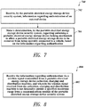
- a method of operating a portable electrical energy storage device security system may be summarized as including receiving, by the portable electrical energy storage device security system, information regarding authentication of an external device; and making a determination, by the portable electrical energy storage device security system, regarding unlocking a portable electrical energy storage device locking mechanism to allow a portable electrical energy storage device to be removed from being operably connected to a vehicle, based on the information regarding authentication.
- the receiving the information may include receiving the information regarding authentication via a wireless signal transmitted from a portable electrical energy storage device collection, charging and distribution machine, and wherein the wireless signal received from the collection, charging and distribution machine may not be detectable outside a specified maximum range from a communications module of the portable electrical energy storage device security system.
- the method may further include sending a signal from a controller of the portable electrical energy storage device security system in a manner to unlock the portable electrical energy storage device locking mechanism in order to allow the portable electrical energy storage device to be removed from being operably connected to the vehicle, if the external device is authenticated based on the information regarding authentication; and sending a signal from the controller of the portable electrical energy storage device security system in a manner to lock the portable electrical energy storage device locking mechanism in order to prevent the portable electrical energy storage device from being removed from being operably connected to the vehicle, if, after a defined period of time, the information regarding authentication of the external device can no longer continue to be received via a communications module of the portable electrical energy storage device.
- the portable electrical energy storage device security system may be integrated as part of the portable electrical energy storage device.
- the portable electrical energy storage device security system may be coupled to the vehicle.
- the making the determination may include comparing a code from the received information regarding authentication to one or more codes associated with the portable electrical energy storage device security system and may further include unlocking the portable electrical energy storage device locking mechanism to allow the portable electrical energy storage device to be removed from being operably connected to the vehicle if the code from the received information regarding authentication matches one of the one or more codes associated with the portable electrical energy storage device; and locking the portable electrical energy storage device locking mechanism in order to prevent the portable electrical energy storage device from being removed from being operably connected to the vehicle, if, after a defined period of time, the information regarding authentication of the external device can no longer be received via a communications module of the portable electrical energy storage device or if, after a defined period of time, a code from the received information can no longer be matched to at least one or one of one or more codes currently associated with the portable electrical energy storage device security system.
- the method may further include generating a challenge key to send to the external device; sending the challenge key to the external device; receiving a response from the external device to the sending of the challenge key, the response including a response code as part of the information regarding authentication; generating an output from a secret algorithm using a secret key and the response code as input, the secret algorithm and the secret key configured to be known only to the portable electrical energy storage device security system and one or more authorized external devices; and comparing the output from the secret algorithm to the response code, and wherein making the determination regarding unlocking the portable electrical energy storage device locking mechanism is based at least on the comparison.
- a portable electrical energy storage device may be summarized as including a battery cell; and a security system operably coupled to the cell, the security system configured to allow the portable electrical energy storage device to be removed from being operably connected to a vehicle, based on information received wirelessly regarding authentication of an external device.
- the security system may include at least one controller; and at least one communications module coupled to the at least one controller, wherein the at least one controller is configured to: receive information regarding authentication of an external device via the communications module; and make a determination regarding unlocking a portable electrical energy storage device locking mechanism to allow the portable electrical energy storage device to be removed from being operably connected to the vehicle, based on the information regarding authentication.
- the security system may further include the portable electrical energy storage device locking mechanism coupled to the at least one controller; and a power interface that is configured to be coupled to the at least one controller and to an auxiliary power source other than the portable electrical energy storage device to provide power to the electrical energy storage device locking mechanism should the portable electrical energy storage device be not able to provide enough power to operate the electrical energy storage device locking mechanism.
- ordinals such as first, second and third does not necessarily imply a ranked sense of order, but rather may only distinguish between multiple instances of an act or structure.
- Reference to portable electrical power storage device means any device capable of storing electrical power and releasing stored electrical power including but not limited to batteries, supercapacitors or ultracapacitors.
- Reference to batteries means chemical storage cell or cells, for instance rechargeable or secondary battery cells including but not limited to nickel cadmium alloy or lithium ion battery cells.
- Figure 1 shows an environment 100 including a collection, charging and distribution machine 102, according to one illustrated example.
- the collection, charging and distribution machine 102 may take the form of a vending machine or kiosk.
- the collection, charging and distribution machine 102 has a plurality of receivers, compartments or receptacles 104a, 104b-104n (only three called out in Figure 1 , collectively 104) to removably receive portable electrical energy storage devices (e.g ., batteries, supercapacitors or ultracapacitors) 106a-106n (collectively 106) for collection, charging and distribution.
- portable electrical energy storage devices e.g ., batteries, supercapacitors or ultracapacitors
- some of the receivers 104 are empty, while other receivers 104 hold portable electrical energy storage devices 106.
- each receiver 104 may hold two or even more portable electrical energy storage devices 106.
- each of the receivers 104 may be sufficiently deep to receive three portable electrical energy storage devices 106.
- the collection, charging and distribution machine 102 illustrated in Figure 1 may have a capacity capable of simultaneously holding 40, 80 or 120 portable electrical energy storage devices 106.
- the portable electrical energy storage devices 106 may take a variety of forms, for example batteries (e.g., array of battery cells) or supercapacitors or ultracapacitors (e.g., array of ultracapacitor cells).
- the portable electrical energy storage device 106z may take the form of rechargeable batteries ( i.e., secondary cells or batteries).
- the portable electrical energy storage device 106z may, for instance, be sized to physically fit, and electrically power, personal transportation vehicles, such as all-electric scooters or motorbikes 108.
- combustion engine scooters and motorbikes are common in many large cities, for example in Asia, Europe and the Middle East. The ability to conveniently access charged batteries throughout a city or region may facilitate the use of all-electric scooters and motorbikes 108 in place of combustion engine scooters and motorbikes, thereby alleviating air pollution, as well as reducing noise.
- the portable electrical energy storage devices 106 may include a number of electrical terminals 110a, 110b (two illustrated, collectively 110), accessible from an exterior of the portable electrical energy storage device 106z.
- the electrical terminals 110 allow charge to be delivered from the portable electrical energy storage device 106z, as well as allow charge to be delivered to the portable electrical energy storage device 106z for charging or recharging the same. While illustrated in Figure 1 as posts, the electrical terminals 110 may take any other form which is accessible from an exterior of the portable electrical energy storage device 106z, including electrical terminals positioned within slots in a battery housing.
- the portable electrical energy storage devices 106 may be lent, leased, and/or rented out to the public, it is desirable to control how and in what circumstances the portable electrical energy storage devices 106 may be removed from being operably connected to the vehicle for which they provide power. This control of the physical security of the portable electrical energy storage devices 106 helps to prevent theft and/or misuse of the portable electrical energy storage devices 106.
- Systems and methods for physical security of the portable electrical energy storage devices 106, including a security system for controlling removal of the portable electrical energy storage devices 106 from a vehicle, are described in more detail below with reference to Figures 3-9 , and are useful in the overall system for collection, charging and distribution of the portable electrical energy storage devices 106 described herein.
- the collection, charging and distribution machine 102 is positioned at some location 112 at which the collection, charging and distribution machine 102 is conveniently and easily accessible by various end users.
- the location may take any of a large variety of forms, for example, a retail environment such as a convenience store, supermarket, gas or petrol station, or service or service center.
- the collection, charging and distribution machine 102 may stand alone at a location 112 not associated with an existing retail or other business, for example in public parks or other public places.
- collection, charging and distribution machines 102 may be located at each store of a chain of convenience stores throughout a city or region. Such may advantageously rely on the fact that convenience stores are often sited or distributed based on convenience to the target population or demographic.
- Such may advantageously rely on pre-existing leases on storefronts or other retail locations to allow an extensive network of collection, charging and distribution machines 102 to be quickly developed in a city or region.
- Quickly achieving a large network that provides for physical security of the of portable electrical energy storage devices 106 while in the all-electric scooters or motorbikes 108 enhances the ability to depend on such a system and likely commercial success of such an effort.
- the location 112 may include an electrical service 114 to receive electrical power from a generating station (not shown) for example via a grid 116.
- the electrical service 114 may, for example, include one or more of an electrical service meter 114a, a circuit panel ( e.g., circuit breaker panel or fuse box) 114b, wiring 114c, and electrical outlet 114d.
- the electrical service 114 may be an existing electrical service, so may be somewhat limited in rating ( e.g., 120 volts, 240 volts, 220 volts, 230 volts, 15 amps).
- the collection, charging and distribution machine 102 may include or be coupled to a source of renewable electrical power.
- the collection, charging and distribution machine 102 may include an array of photovoltaic (PV) cells 118 to produce electrical power from solar insolation.
- the collection, charging and distribution machine 102 may be electrically coupled to a microturbine (e.g ., wind turbine) or PV array positioned elsewhere at the location 112, for instance on a roof top or mounted at a top of a pole (not shown).
- the collection, charging and distribution machine 102 may be communicatively coupled to one or more remotely located computer systems, such as back end or back office systems (only one shown) 120.
- the back end or back office systems 120 may collect data from and/or control a plurality of collection, charging and distribution machines 102 distributed about an area, such as a city.
- the back end or back office systems 120 may collect data from and/or control a plurality of the portable electrical energy storage devices 106, such as by generating, tracking, sending and/or receiving one or more codes included in a wireless signal 126 sent by the collection, charging and distribution machine 102 to an all-electric scooter or motorbike 108 or other vehicle.
- the sending and/or receiving one or more codes enables access to the portable electrical energy storage devices 106 for removal from a respective all-electric scooter or motorbike 108 while the all-electric scooter or motorbike 108 is in the vicinity of the collection, charging and distribution machine 102.
- the communications between the back end or back office systems 120 and the collection, charging and distribution machine 102 may occur over one or more communications channels including one or more networks 122, or non-networked communications channels. Communications may be over one or more wired communications channels (e.g ., twisted pair wiring, optical fiber), wireless communications channels ( e.g ., radio, microwave, satellite, 801.11 compliant).
- Networked communications channels may include one or more local area networks (LANs), wide area networks (WANs), extranets, intranets, or the Internet including the World Wide Web portion of the Internet.
- the collection, charging and distribution machine 102 may include a user interface 124.
- the user interface may include a variety of input/output (I/O) devices to allow an end user to interact with the collection, charging and distribution machine 102.
- I/O input/output
- Various I/O devices are called out and described in reference to Figure 2 , which follows.
- Figure 2 shows the collection, charging and distribution machine 102 of Figure 1 , according to one illustrated example.
- the collection, charging and distribution machine 102 includes a control subsystem 202, a charging subsystem 204, a communications subsystem 206, and a user interface subsystem 208.
- the control subsystem 202 includes a controller 210, for example a microprocessor, microcontroller, programmable logic controller (PLC), programmable gate array (PGA), application specific integrated circuit (ASIC) or another controller capable of receiving signals from various sensors, performing logical operations, and sending signals to various components.
- the controller 210 may take the form of a microprocessor (e.g ., INTEL, AMD, ATOM).
- the control subsystem 202 may also include one or more non-transitory processor- or computer-readable storage media, for example read only memory (ROM) 212, random access memory (RAM) 214, and data store 216 (e.g ., solid-state storage media such as flash memory or EEPROM, or spinning storage media such as hard disk).
- the non-transitory processor- or computer-readable storage media 212, 214, 216 may be in addition to any non-transitory storage medium (e.g ., registers) which is part of the controller 210.
- the control subsystem 202 may include one or more buses 218 (only one illustrated) coupling various components together, for example one or more power buses, instruction buses, data buses, etc.
- the ROM 212 stores instructions and/or data or values for variables or parameters.
- the sets of data may take a variety of forms, for example a lookup table, a set of records in a database, etc.
- the instructions and sets of data or values are executable by the controller 110.
- Execution of the instructions and sets of data or values causes the controller 110 to perform specific acts to cause the collection, charging and distribution machine 102 to collect, charge, and distribute portable energy storage devices, and to send one or more signals that enable access to the portable electrical energy storage devices 106 for removal from the all-electric scooters or motorbikes 108 while the all-electric scooters or motorbikes 108 are in the vicinity of a collection, charging and distribution machine 102 .
- Specific operation of the collection, charging and distribution machine 102 is described herein and also below with reference to Figure 3 and various flow diagrams ( Figures 7-9 ) in the context of being an external device which is authenticated in order to allow the portable electrical energy storage device 106 to be removed from being operably connected to the all-electric scooter or motorbike 108.
- the controller 210 may use RAM 214 in a conventional fashion, for volatile storage of instructions, data, etc.
- the controller 210 may use data store 216 to log or retain information, for example one or more codes that enable access to the portable electrical energy storage devices 106 for removal from the all-electric scooters or motorbikes 108 while the all-electric scooters or motorbikes 108 are in the vicinity of the collection, charging and distribution machine 102, and/or information related to operation of the collection, charging and distribution machine 102 itself.
- the instructions are executable by the controller 210 to control operation of the collection, charging and distribution machine 102 in response to end user or operator input, and using data or values for the variables or parameters.
- the control subsystem 202 receives signals from various sensors and/or other components of the collection, charging and distribution machine 102 which include information that characterizes or is indicative of operation, status, or condition of such other components. Sensors are represented in Figure 2 by the letter S appearing in a circle along with appropriate subscript letters.
- one or more position sensors S P1 -S PN may detect the presence or absence of a portable electrical power storage device 106 at each of the receivers 104.
- the position sensors S P1 -S PN may take a variety of forms.
- the position sensors S P1 -S PN may take the form of mechanical switches that are closed, or alternatively opened, in response to contact with a portion of a respective portable electrical power storage device 106 when the portable electrical power storage device 106 is inserted into the receiver 104.
- the position sensors S P1 -S PN may take the form of optical switches (i.e., optical source and receiver) that are closed, or alternatively opened, in response to contact with a portion of a respective portable electrical power storage device 106 when the portable electrical power storage device 106 is inserted into the receiver 104.
- the position sensors S P1 -S PN may take the form of electrical sensors or switches that are closed, or alternatively opened, in response to detecting a closed circuit condition created by contact with the terminals 110 of a respective portable electrical power storage device 106 when the portable electrical power storage device 106 is inserted into the receiver 104, or an open circuit condition that results from the lack of a respective portable electrical power storage device 106 in the receiver 104.
- one or more charge sensors S C1 -S CN may detect charge of the portable electrical power storage devices 106 at each of the receivers 104.
- Charge sensors S C1 -S CN may detect the amount of charge stored by the portable electrical power storage devices 106.
- Charge sensors S C1 -S CN may additionally detect an amount of charge and/or rate of charging being supplied to ones of the portable electrical power storage devices 106 at each of the receivers 104. Such may allow assessment of current ( i.e., temporal) charge condition or status of each portable electrical power storage device 106, as well as allow feedback control over charging of same, including control over rate of charging.
- Charge sensors S C1 -S CN may include any variety of current and/or voltage sensors.
- one or more charge sensors S T1 may detect or sense a temperature at the receivers 104 or in the ambient environment.
- the control subsystem 202 provides signals to various actuators and/or other components responsive to control signals, which signals include information that characterizes or is indicative of an operation the component is to perform or a state or condition into which the components should enter.
- Control signals, actuators or other components responsive to control signals are represented in Figure 2 by the letter C appearing in a circle along with appropriate subscript letters.
- one or more engine control signals C A1 -C AN may affect the operation of one or more actuators 220 (only one illustrated).
- a control signal C A1 may cause movement of an actuator 220 between a first and a second position or change a magnetic field produced by the actuator 220.
- the actuator 220 may take any of a variety of forms, including but not limited to a solenoid, an electric motor such as a stepper motor, or an electromagnet.
- the actuator 220 may be coupled to operate a latch, lock or other retainer mechanism 222.
- the latch, lock or other retainer mechanism 222 may selectively secure or retain one or more portable electrical power storage devices 106 ( Figure 1 ) in the receiver 104 ( Figure 1 ).
- the latch, lock or other retainer mechanism 222 may physically couple to a complimentary structure that is part of a housing of the portable electrical power storage devices 106 ( Figure 1 ).
- the latch, lock or other retainer mechanism 222 may magnetically couple to a complimentary structure that is part of a housing of the portable electrical power storage devices 106 ( Figure 1 ).
- the latch, lock or other retainer mechanism 222 may open a receiver 104 ( Figure 1 ), or may allow a receiver 104 to be opened, to receive a partially or fully discharged portable electrical power storage device 106 for charging.
- the actuator may open and/or close a door to the receiver 104 ( Figure 1 ), to selectively provide access to a portable electrical power storage device 106 ( Figure 1 ) received therein.
- the actuator may open and/or close a latch or lock, allowing an end user to open and/or close a door to the receiver 104 ( Figure 1 ), to selectively provide access to a portable electrical power storage device 106 ( Figure 1 ) received therein.
- the control subsystem 202 may include one or more ports 224a to provide control signals to one or more ports 224b of the charging subsystem 204.
- the ports 224a, 224b may provide bi-directional communications.
- the control subsystem 202 may include one or more ports 226a to provide control signals to one or more ports 226b of the user interface subsystem 208.
- the ports 226a, 226b may provide bi-directional communications.
- the charging subsystem 204 includes various electrical and electronic components to charge portable electrical power storage devices 106 when positioned or received in the receivers 104.
- the charging subsystem 204 may include one or more power buses or power bus bars, relays, contactors or other switches (e.g., insulated gate bipolar transistors or IGBTs, metal oxide semiconductor transistors or MOSFETs), rectifier bridge(s), current sensors, ground fault circuitry, etc.
- the electrical power is supplied via contacts that can take any of a variety of forms, for instance terminals, leads, posts, etc. The contacts allow electrical coupling of various components. Some possible implementations are illustrated in Figure 2 . Such is not intended to be exhaustive. Additional components may be employed while other components may be omitted.
- the illustrated charging subsystem 204 includes a first power converter 230 that receives electrical power from the electrical service 114 ( Figure 1 ) via a line or cord 232.
- the power will typically be in the form of single two- or three-phase AC electrical power.
- the first power converter 230 may need to convert and otherwise condition the electrical power received via the electrical services 114 ( Figure 1 ), for example for rectifying an AC waveform to DC, transforming voltage, current, and phase, as well as reducing transients and noise.
- the first power converter 230 may include a transformer 234, rectifier 236, DC/DC power converter 238, and filter(s) 240.
- the transformer 234 may take the form of any variety of commercially available transformers with suitable ratings for handling the power received via the electrical service 114 ( Figure 1 ). Some examples may employ multiple transformers. The transformer 234 may advantageously provide galvanic isolation between the components of the collection, charging and distribution machine 102 and the grid 116 ( Figure 1 ).
- the rectifier 236 may take any of variety of forms, for example a full bridge diode rectifier or a switch mode rectifier. The rectifier 236 may be operated to transform AC electrical power to DC electrical power.
- the DC/DC power converter 238 may take any of a large variety of forms.
- DC/DC power converter 238 may take the form a switch mode DC/DC power converter, for instance employing IGBTs or MOSFETs in a half or full bridge configuration, and may include one or more inductors.
- the DC/DC power converter 238 may have any number of topologies including a boost converter, buck converter, synchronous buck converter, buck-boost converter or fly-back converter.
- the filter(s) 240 may include one or more capacitors, resistors, Zener diodes or other elements to suppress voltage spikes, or to remove or reduce transients and/or noise.
- the illustrated charging subsystem 204 may also receive electrical power from a renewable power source, for example the PV array 118 ( Figure 1 ). Such may be converted or conditioned by the first power converter 230, for example being supplied directly to the DC/DC power converter 238, bypassing the transformer 236 and/or rectifier 236. Alternatively, the illustrated charging subsystem 204 may include a dedicated power converter to convert or otherwise condition such electrical power.
- a renewable power source for example the PV array 118 ( Figure 1 ).
- the first power converter 230 for example being supplied directly to the DC/DC power converter 238, bypassing the transformer 236 and/or rectifier 236.
- the illustrated charging subsystem 204 may include a dedicated power converter to convert or otherwise condition such electrical power.
- the illustrated charging subsystem 204 may optionally include second power converter 242 that receives electrical power from one or more portable electrical power storage devices 106 ( Figure 1 ) via one or more lines 244, for charging other ones of the portable electrical power storage devices 106.
- the second power converter 242 may need to convert and/or otherwise condition the electrical power received from portable electrical power storage devices 106, for example optionally transforming voltage or current, as well as reducing transients and noise.
- the second power converter 242 may optionally include a DC/DC power converter 246 and/or filter(s) 248.
- DC/DC power converter 246 and/or filter(s) 248.
- DC/DC power converters and filters are discussed above.
- the illustrated charging subsystem 204 includes a plurality of switches 250 responsive to the control signals delivered via ports 224a, 224b from the control subsystem 202.
- the switches may be operable to selectively couple a first number or set of portable electrical power storage devices 106 to be charged from electrical power supplied by both the electrical service via the first power converter 230 and from electrical power supplied by a second number or set of portable electrical power storage devices 106.
- the first number or set of portable electrical power storage devices 106 may include a single portable electrical power storage device 106, two, or even more portable electrical power storage devices 106.
- the second number or set of portable electrical power storage devices 106 may include a single portable electrical power storage device 106, two, or even more portable electrical power storage devices 106.
- the portable electrical power storage devices 106 are represented in Figure 2 as loads L 1 ,L 2 -L N .
- the communications subsystem 206 may additionally include one or more communications modules or components which facilitate communications with the various components of a back end or back office system 120 ( Figure 1 ), various components of the all-electric scooter or motorbike 108, and/or various components of the portable electrical power storage devices 106.
- the communications subsystem 206 may, for example, include one or more modems 252 and/or one or more Ethernet cards or other types of communications cards or components 254.
- a port 256a of the control subsystem 202 may communicatively couple the control subsystem 202 with a port 256b of the communications subsystem 206.
- the communications subsystem 206 may provide wired and/or wireless communications.
- the communications subsystem 206 may provide components enabling short range (e.g., via Bluetooth, near field communication (NFC), radio frequency identification (RFID) components and protocols) or longer range wireless communications (e.g ., over a wireless LAN, satellite, or cellular network) with various other devices external to the collection, charging and distribution machine 102, including various components of the all-electric scooter or motorbike 108, and/or various components of the portable electrical power storage devices 106.
- the communications subsystem 206 may include one or more ports, wireless receivers, wireless transmitters or wireless transceivers to provide wireless signal paths to the various remote components or systems.
- the communications subsystem 206 may include one or more bridges or routers suitable to handle network traffic including switched packet type communications protocols (TCP/IP), Ethernet or other networking protocols.
- TCP/IP switched packet type communications protocols
- Ethernet Ethernet
- the user interface subsystem 208 includes one or more user input/output (I/O) components.
- user interface subsystem 208 may include a touch screen display 208a operable to present information to an end user, and a graphical user interface (GUI) to receive indications of user selections.
- GUI graphical user interface
- the user interface subsystem 208 may include a keyboard or keypad 208b, and/or a cursor controller ( e.g ., mouse, trackball, trackpad) (not illustrated) to allow an end user to enter information and/or select user selectable icons in a GUI.
- the user interface subsystem 208 may include a speaker 208c to provide aural messages to an end user and/or a microphone 208d to receive spoken user input such as spoken commands.
- the user interface subsystem 208 may include a card reader 208e to read information from card type media 209.
- the card reader 208e may take a variety of forms.
- the card reader 208e may take the form of, or include, a magnetic stripe reader for reading information encoded in a magnetic stripe carried by a card 209.
- the card reader 208e may take the form of, or include, a machine-readable symbol (e.g., barcode, matrix code) card reader for reading information encoded in a machine-readable symbol carried by a card 209.
- the card reader 208e may take the form of, or include, a smart card reader for reading information encoded in a non-transitory medium carried by a card 209.
- Such may, for instance, include media employing radio frequency identification (RFID) transponders or electronic payment chips (e.g., near filed communications (NFC) chips).
- RFID radio frequency identification
- NFC near filed communications
- the card reader 208e may be able to read information from a variety of card media 209, for instance credit cards, debit cards, gift cards, prepaid cards, as well as identification media such as drivers licenses.
- the card reader 208e may also be able to read information encoded in a non-transitory medium carried by the portable electrical energy storage devices 106, and may also include RFID transponders, transceivers, NFC chips and/or other communications devices to communicate information to various components of the all-electric scooter or motorbike 108, and/or various components of the portable electrical power storage devices 106 ( e.g., for authentication of the collection, charging and distribution machine 102 to the portable electrical energy storage devices 106 and/or the all-electric scooter or motorbike 108, or for authentication of the portable electrical energy storage devices 106 to the collection, charging and distribution machine 102).
- the user interface subsystem 208 may include a bill acceptor 208f and a validator and/or coin acceptor 208g to accept and validate cash payments. Such may be highly useful in servicing populations lacking access to credit. Bill acceptor and validator 208f and/or coin acceptor 208g may take any variety of forms, for example those that are currently commercially available and used in various vending machines and kiosks.
- Figure 3 shows a portable electrical energy storage device physical security system for the portable electrical energy storage device 106z of the scooter or motorbike 108 in wireless communication in one instance with the collection, charging and distribution machine 102 and in another instance with a device at a scooter or motorbike service center 318, according to one non-limiting illustrated embodiment.
- a portable electrical energy storage device locking mechanism 320 operably coupled to a locking mechanism controller 306.
- the portable electrical energy storage device locking mechanism 320 and the locking mechanism controller 306 are part of the scooter or motorbike 108. In other embodiments, the portable electrical energy storage device locking mechanism 320 and the locking mechanism controller 306 are integrated with or part of the portable electrical energy storage device 106z.
- the collection, charging and distribution machine 102 in wireless communication with the locking mechanism controller 306.
- the communications subsystem 206 (shown in Figure 2 ) of the collection, charging and distribution machine 102 may provide components enabling short range (e.g ., via Bluetooth, near field communication (NFC), radio frequency identification (RFID) components and protocols) or longer range wireless communications (e.g ., over a wireless LAN, satellite, or cellular network) with various other devices external to the collection, charging and distribution machine 102, including the locking mechanism controller 306.
- the communications subsystem 206 of the collection, charging and distribution machine 102 may include one or more ports, wireless receivers, wireless transmitters or wireless transceivers to provide wireless signal paths to the locking mechanism controller 306.
- the communications subsystem 206 of the collection, charging and distribution machine 102 may also or instead include one or more bridges or routers suitable to handle network traffic including switched packet type communications protocols (TCP/IP), Ethernet or other networking protocols.
- TCP/IP switched packet type communications protocols
- the portable electrical energy storage device 106z may be lent, leased, and/or rented out to the public. Since the portable electrical energy storage device 106z is typically a relatively expensive component, it is desirable to control how and in what circumstances the portable electrical energy storage device 106z may be removed from being operably connected or attached to the scooter or motorbike 108 for which it provides power. This control of the physical security of the portable electrical energy storage device 106z helps to prevent theft and/or misuse of the portable electrical energy storage device 106z.
- the portable electrical energy storage device 106z may be operably connected to and physically locked or otherwise physically secured in the scooter or motorbike 108 until the locking mechanism controller 306 detects a wireless signal including authentication information from an external device such as the collection, charging and distribution machine 102 or a device at a service center 306 with one or more wireless communications subsystems such as that described above of the collection, charging and distribution machine 102.
- Other such external devices (not shown) with one or more wireless communications subsystems such as that described above of the collection, charging and distribution machine 102 may include, but are not limited to: card keys, access cards, credit cards, access control key fobs, mobile computing devices, cellular telephones, personal digital assistants (PDAs), smart phones, battery chargers, other access control devices, etc.
- the collection, charging and distribution machine 102 may periodically, constantly or aperiodically emit a wireless signal 126 for a locking mechanism controller 306 listening for such a signal to receive and authenticate the collection, charging and distribution machine 102 in order to trigger the portable electrical energy storage device locking mechanism 320 to unlock, enabling the portable electrical energy storage device 106z to be removed from the scooter or motorbike 108.
- the locking mechanism controller 306 may periodically or constantly emit a wireless signal 126 to which a collection, charging and distribution machine 102 listening for such a signal will respond with a wireless signal for the locking mechanism controller 306 to receive and authenticate the collection, charging and distribution machine 102 in order to trigger the portable electrical energy storage device locking mechanism 320 to unlock, enabling the portable electrical energy storage device 106z to be removed from the scooter or motorbike 108.
- the wireless signal received from the collection, charging and distribution machine 102 may include a code that may be authenticated by the locking mechanism controller 306 in order to ensure the signal is being received from an authorized device.
- the code may be time-sensitive code such as a "hopping" code or a "rolling" code to provide such security. In the case of a 40-bit rolling code, forty bits provide 240 (about 1 trillion) possible codes. However, codes of other bit lengths may be used instead.
- the collection, charging and distribution machine 102 memory e.g., ROM 212) may hold the current 40-bit code.
- the collection, charging and distribution machine 102 then sends that 40-bit code to the locking mechanism controller 306 for the locking mechanism controller 306 to unlock the portable electrical energy storage device locking mechanism 320.
- the locking mechanism controller 306 also holds the current 40-bit code. If the locking mechanism controller 306 receives the 40-bit code it expects, then it unlocks the portable electrical energy storage device locking mechanism 320. If the locking mechanism controller 306 does not receive the 40-bit code it expects, the locking mechanism controller 306 does nothing.
- the locking mechanism controller 306 will lock the portable electrical energy storage device locking mechanism 320 if the portable electrical energy storage device locking mechanism 320 is in an unlocked state and the locking mechanism controller 306 does not receive the 40-bit code it expects, or is not able to receive any signal over a determined period of time.
- Both the collection, charging and distribution machine 102 and the locking mechanism controller 306 use the same pseudo-random number generator (e.g ., implemented by the respective processors of the collection, charging and distribution machine 102 and the locking mechanism controller 306) to generate the 40-bit code.
- the collection, charging and distribution machine 102 may have different pseudo-random number generators to match the pseudo-random number generator of each locking mechanism controller 306 of each scooter or motorbike 108 or of each of the portable electrical energy storage devices 106.
- the locking mechanism controller 306 When the locking mechanism controller 306 receives a valid code form the collection, charging and distribution machine 102, it uses the same pseudo-random number generator to generate the next code relative to the valid code received and communicates wirelessly with the collection, charging and distribution machine 102 to instruct it to also generate the next code using the same pseudo-random number generator, which the collection, charging and distribution machine 102 stores for the next use. In this way, the collection, charging and distribution machine 102 and the locking mechanism controller 306 are synchronized. The locking mechanism controller 306 only unlocks the portable electrical energy storage device locking mechanism 320 if it receives the code it expects.
- the current 40-bit code or other time-sensitive rolling code may be generated and communicated to one or more other collection, charging and distribution machines within a network of collection, charging and distribution machines ( e.g., via the network 122 shown in Figure 1 ) so that any collection, charging and distribution machine 102 may communicate the correct current code to the locking mechanism controller 306 when the scooter or motorbike having the locking mechanism controller 306 or the portable electrical energy storage device 106z having the locking mechanism controller 306 comes within wireless signal range of the other collection, charging and distribution machines.
- the locking mechanism controller 306 may accept any of the next 256 possible valid codes in the pseudo-random number sequence.
- the locking mechanism controller 306 would still accept the transmission from the collection, charging and distribution machine 102, unlock the portable electrical energy storage device locking mechanism 320 and generate the next code relative to the valid code received.
- the hopping, rolling or time-sensitive code may be a universal code communicated by the back end or back office system 120 to the collection, charging and distribution machine 102 and communicated wirelessly to the locking mechanism controller 306. For example, this may occur over a WAN, LAN and/or when the locking mechanism controller 306 comes within wireless communications range of the collection, charging and distribution machine 102 such as when the scooter or motorbike 108 visits the collection, charging and distribution machine 102.
- the locking mechanism controller 306 and the collection, charging and distribution machine store a common secret key or code and use a common secret algorithm for authentication of the collection, charging and distribution machine.
- the common secret algorithm for example, can be a hash function or other algorithm which takes the secret key and at least one other key or code as input and generates different output based on the secret key and different input.
- the common secret algorithm may be executed by respective processors of the locking mechanism controller 306 and the collection, charging and distribution machine using stored instructions on respective computer readable media of the locking mechanism controller 306 and the collection, charging and distribution machine or on respective configured hardware or firmware components of the of locking mechanism controller 306 and collection, charging and distribution machine.
- the common secret algorithm and common secret key or code may be initially encoded, programmed or installed in the locking mechanism controller 306 and collection, charging and distribution machine in a secure fashion such that they are irretrievable or otherwise protected from being discovered.
- the common secret algorithm and common secret key or code are not communicated between the locking mechanism controller 306 and collection, charging and distribution machine during the authentication process.
- the locking mechanism controller 306 In response to receiving an authentication beacon or request from the collection, charging and distribution machine via the wireless signal 126 (which may have been sent in response to a wireless signal or beacon received from the locking mechanism controller 306), the locking mechanism controller 306 generates a challenge key and sends this challenge key to the collection, charging and distribution machine. In response to receiving the challenge key, the collection, charging and distribution machine uses the secret algorithm and the common secret key to generate a response value and sends this response value to the locking mechanism controller 306. The locking mechanism controller 306 then verifies the response value by using the generated challenge key and secret key as input to the secret algorithm to generate an output value from the secret algorithm. The locking mechanism controller 306 then compares this output value from the secret algorithm to the response value received from the collection, charging and distribution machine.
- the collection, charging and distribution machine is authenticated and the locking mechanism controller 306 may then take actions accordingly, such as sending a control signal to the locking mechanism 320 to unlock. If the output from the secret algorithm generated by the locking mechanism controller 306 and the response value received from the collection, charging and distribution machine do not match, then the collection, charging and distribution machine is not authenticated and the locking mechanism controller 306 may then take no action, or take other actions accordingly, such as sending a control signal to the locking mechanism 320 to lock if not already locked. In some embodiments any authentication process involving using any combination of a public key and or public algorithm may be used.
- the locking mechanism controller 306 can no longer receive the wireless signal 126 from the collection, charging and distribution machine 102 (e.g., after the scooter or motorbike has already exchanged the portable electrical energy storage device 106z at the collection, charging and distribution machine 102 and is no longer within range of the collection, charging and distribution machine 102 wireless signal 126), the locking mechanism controller 306 will send a signal to cause the portable electrical energy storage device locking mechanism 320 to lock to prevent the portable electrical energy storage device 106z from being able to be removed from being operably connected to the scooter or motorbike 108.
- the locking mechanism controller 306 will send a signal to cause the portable electrical energy storage device locking mechanism 320 to lock to prevent the portable electrical energy storage device 106z from being able to be removed from being operably connected to the scooter or motorbike.
- the locking mechanism controller 306 is not part of the portable electrical energy storage device 106z, the locking mechanism controller 306 must detect the presence of the portable electrical energy storage device 106z in the scooter or motorbike 108 before sending a signal to cause the portable electrical energy storage device locking mechanism 320 to lock.
- the wireless portion of the authentication is strongly phased.
- the system challenges some or all portable electrical energy storage device collection, charging and distribution machines that would wirelessly tell the vehicle to disengage the portable electrical energy storage device in order to swap the portable electrical energy storage device.
- the portable electrical energy storage device collection, charging and distribution machine/service center may be mobile.
- a service vehicle may come to a broken down/out of charge vehicle on the side of the road and the portable electrical energy storage device can only release when the authenticated service vehicle is nearby.
- Nearby may be any range of distance selected by the system within range of short range wireless signal. A very short close distance may also be used, for example, as in some embodiments, the system may use technology such as near field communications (NFC) or other near field or very short range technologies.
- NFC near field communications
- Figure 4 is a schematic view of the locking mechanism controller of Figure 3 , according to one non-limiting illustrated embodiment.
- the locking mechanism controller 306 includes a controller 410, a communications subsystem 406, and a power interface 420.
- the controller 410 is a microprocessor, microcontroller, programmable logic controller (PLC), programmable gate array (PGA), application specific integrated circuit (ASIC) or another controller capable of receiving signals from various sensors, performing logical operations, and sending signals to various components.
- the controller 410 may take the form of a microprocessor (e.g ., INTEL, AMD, ATOM).
- the locking mechanism controller 306 may also include one or more non-transitory processor- or computer-readable storage media, for example read only memory (ROM) 412, random access memory (RAM) 414, and other storage 416 (e.g., solid-state storage media such as flash memory or EEPROM, or spinning storage media such as hard disk).
- the non-transitory processor- or computer-readable storage media 412, 414, 416 may be in addition to any non-transitory storage medium (e.g., registers) which is part of the controller 410.
- the locking mechanism controller 306 may include one or more buses 418 (only one illustrated) coupling various components together, for example one or more power buses, instruction buses, data buses, etc.
- the ROM 412 stores instructions and/or data or values for variables or parameters.
- the sets of data may take a variety of forms, for example a lookup table, a set of records in a database, etc.
- the instructions and sets of data or values are executable by the controller 410. Execution of the instructions and sets of data or values causes the controller 410 to perform specific acts to compare a code received from an external device and cause the locking mechanism controller 306 to generate control signals to lock or unlock the portable electrical energy storage device locking mechanism 320 based on the comparison. Also, such acts may include, for example, operations implementing a pseudo-random number to generate a rolling code as described above. Specific operation of the locking mechanism controller 306 is described herein and also below with reference to various flow diagrams ( Figures 7-9 ).
- the controller 410 may use RAM 414 in a conventional fashion, for volatile storage of instructions, data, etc.
- the controller 410 may use data store 416 to log or retain information, for example, information regarding user profile information, vehicle profile information, security codes, credentials, security certificates, passwords, vehicle information, etc.
- the instructions are executable by the controller 410 to control operation of the locking mechanism controller 306 in response to input from remote systems such as those of external devices including but not limited to: charging devices, vehicles, user identification devices (cards, electronic keys, etc.) vehicles, collection, charging and distribution machines, collection, charging and distribution machine service systems, service centers, user mobile devices, user vehicles, and end user or operator input.
- the controller 410 may also receive signals from various sensors and/or components of an external device via the communications subsystem 406 of the locking mechanism controller 306. This information may include information that characterizes or is indicative of the authenticity, authorization level, operation, status, or condition of such components and/or external devices.
- the communications subsystem 406 may include one or more communications modules or components which facilitate communications with the various components of the collection, charging and distribution machine 102 of Figure 1 (e.g., such as to receive a security code) and/or of other external devices and also, such that data may be exchanged between the locking mechanism controller 306 and the external devices for authentication purposes.
- the communications subsystem 406 may provide wired and/or wireless communications.
- the communications subsystem 406 may include one or more ports, wireless receivers, wireless transmitters or wireless transceivers to provide wireless signal paths to the various remote components or systems.
- the communications subsystem 406 may, for example, include components enabling short range (e.g ., via Bluetooth, near field communication (NFC), radio frequency identification (RFID) components and protocols) or longer range wireless communications (e.g. , over a wireless LAN, satellite, or cellular network) and may include one or more modems or one or more Ethernet or other types of communications cards or components for doing so.
- the remote communications subsystem 406 may include one or more bridges or routers suitable to handle network traffic including switched packet type communications protocols (TCP/IP), Ethernet or other networking protocols.
- some or all of the components of the locking mechanism controller 306 may be located outside of the portable electrical energy storage device 106z as a separate device that actuates one or more actuators 502 (shown in Figure 6 and Figure 7 ) of the portable electric al energy storage device 106z ( e.g., by a wireless control signal) sent via the communications subsystem 406.
- the power interface 420 is controllable by the controller 410 and is configured to receive power from the portable electrical energy storage device 106z via connection 314a to provide power to the locking mechanism controller 306 and also to the portable electrical energy storage device locking mechanism 320 (via connection 314b). Also, the power interface 420 is controllable by the controller 410 and is configured to receive power from an auxiliary source other than the portable electrical energy storage device 106z via connection 314c to provide power to the portable electrical energy storage device locking mechanism 320 and/or the locking mechanism controller 306 should the portable electrical energy storage device 106z be not able to provide enough power to operate the portable electrical energy storage device locking mechanism 320 and/or the locking mechanism controller 306.
- the power interface 420 includes various components operable for performing the above functions such as electrical transformers, converters, rectifiers, etc.
- Figure 5 shows a cross-sectional elevation view of the portable electrical energy storage device 106z of Figure 1 and Figure 3 coupled to the portable electrical energy storage device physical security system of Figure 3 and locked in an operable position within the scooter 108 of Figure 1 and Figure 3 , according to one non-limiting illustrated embodiment.
- a portable electrical energy storage device holder 510 Shown is a portable electrical energy storage device holder 510, a part of a vehicle 508, a portable electrical energy storage device housing 302, electrical terminals 110a, 110b, a battery cell 304, a locking mechanism controller 306, a portable electrical energy storage device locking mechanism 320 and an auxiliary power source 516.
- the battery cell 304 may be any rechargeable type of electrochemical cell that converts stored chemical energy into electrical energy.
- the battery cell 304 may comprise any type of rechargeable ultracapacitor array or fuel cell array.
- the electrical terminals 110a, 110b are accessible from an exterior of the portable electrical energy storage device 106z.
- the electrical terminals 110 allow charge to be delivered from the portable electrical energy storage device 106z, as well as allow charge to be delivered to the portable electrical energy storage device 106z for charging or recharging the same through conductive terminal connections 312a and 312b to the battery cell 304. While illustrated in Figure 3 as posts, the electrical terminals 110a and 110b may take any other form which is accessible from an exterior of the portable electrical energy storage device 106z, including electrical terminals positioned within slots in the battery housing 302.
- the portable electrical energy storage device locking mechanism 320 is located outside the portable electrical energy storage device housing 302 and fixedly attached to a vehicle part 508 ( e.g., a vehicle frame or chassis) that is attached to a holder 510 in which the portable electrical energy storage device 106z is placed.
- vehicle part 508 e.g., a vehicle frame or chassis
- the holder 510 has a top opening 512 through which the portable electrical energy storage device 106z may be placed into the holder 510 and removed from the holder 510. Once the portable electrical energy storage device 106z is placed in the holder 510, the holder 510 surrounds the portable electrical energy storage device 106z except at the top opening 512.
- the portable electrical energy storage device locking mechanism 320 has a slidable bolt 506 which partially covers the opening 512 (as shown in Figure 5 ) in a locked state to block passage of the portable electrical energy storage device 106z through the opening 512 and thus prevent the portable electrical energy storage device 106z from being able to be removed from the holder 510.
- the slidable bolt 506 is slidable on a bolt track or through bolt housing 504 fixedly attached to the vehicle part 508.
- the slidable bolt 506 is retracted (not shown) into the bolt housing 504 to not cover the opening 512 and thus allow passage of the portable electrical energy storage device 106z through the opening 512 of the holder 510 for the portable electrical energy storage device 106z to be removed.
- the portable electrical energy storage device locking mechanism 320 is coupled to the locking mechanism controller 306 via a control line 308 and power line 314b.
- one or more engine control signals received from the locking mechanism controller 306 via control line 308 may affect the operation of one or more actuators 502 (only one illustrated) to cause the slidable bolt 506 to move.
- a control signal may cause movement of an actuator 502 between a first and a second position or change a magnetic field produced by the actuator 502.
- the actuator 502 may take any of a variety of forms, including but not limited to a solenoid, an electric motor such as a stepper motor, or an electromagnet.
- the actuator 502 may alternatively be coupled to operate a different latch, lock or other type of retainer mechanism for the portable electrical energy storage device 106z.
- the locking mechanism controller 306 is configured to receive power from the portable electrical energy storage device 106z via connection 314a to provide power to the locking mechanism controller 306 and also to the portable electrical energy storage device locking mechanism 320 (via connection 314b). Also, the locking mechanism controller 306 is optionally configured to receive power from an auxiliary source 516 other than the portable electrical energy storage device 106z via connection 314c to provide power to the portable electrical energy storage device locking mechanism 320 and/or the locking mechanism controller 306 should the portable electrical energy storage device 106z be not able to provide enough power to operate the portable electrical energy storage device locking mechanism 320 and/or the locking mechanism controller 306.
- the housing 302 may provide a protection to prevent or deter tampering, and may be formed of suitably strong and resilient materials (e.g ., ABS plastic). Such may not only prevent or deter tampering, but may leave a visible indication of any tampering attempts.
- the housing 302 may include a strong outer layer of a first color (e.g., black) within an inner layer of a second color (e.g., fluorescent orange) therebeneath. Such will render attempts to cut through the housing 302 visibly apparent.
- the housing 302 may serve as a frangible substrate, or a frangible substrate may be secured to an inner portion of the housing 302, for instance, via suitable adhesives.
- tampering with the housing may break or damage a circuit connection, rendering the portable electrical energy storage device 106z inoperable.
- Figure 6 shows a cross-sectional elevation view of an alternative embodiment the portable electrical energy storage device 106z of Figure 1 and Figure 3 in which the portable electrical energy storage device physical security system of Figure 3 is integrated with and part of the portable electrical energy storage device 106z of Figure 1 and Figure 3 , according to one non-limiting illustrated alternative embodiment.
- the battery cell 304 is any rechargeable type of electrochemical cell that converts stored chemical energy into electrical energy. As described above, the electrical terminals 1 10a, 110b are accessible from an exterior of the portable electrical energy storage device 106z.
- the portable electrical energy storage device locking mechanism 320 is located inside the portable electrical energy storage device housing 302 and fixedly attached to the interior of the portable electrical energy storage device housing 302.
- the holder 510 has a top opening 512 through which the portable electrical energy storage device 106z may be placed into the holder 510 and removed from the holder 510. Once the portable electrical energy storage device 106z is placed in the holder 510, the holder 510 surrounds the portable electrical energy storage device 106z except at the top opening 512.
- the portable electrical energy storage device locking mechanism 320 has a slidable bolt 506 which is configured to slide on a bolt track or through bolt housing 504 fixedly attached to an interior wall of the portable electrical energy storage device housing 502.
- the slidable bolt 506 is configured to slide through an opening 520 in the side of the housing 302 and into an opening 520 in the side wall of the holder 510 aligned with the opening in the side of the housing 302 to block passage of the portable electrical energy storage device 106z through the top opening 512 of the holder 510, and thus prevent the portable electrical energy storage device 106z from being able to be removed from the holder 510 (as shown in Figure 6 ).
- the slidable bolt 506 When the portable electrical energy storage device locking mechanism 320 is in an unlocked state, the slidable bolt 506 is retracted (not shown) back into the bolt housing 504 inside the portable electrical energy storage device 106z, and thus allows passage of the portable electrical energy storage device 106z through the top opening 512 of the holder 510 for the portable electrical energy storage device 106z to be removed.
- the portable electrical energy storage device locking mechanism 320 is coupled to the locking mechanism controller 306 via a control line 308 and power line 314b.
- one or more engine control signals received from the locking mechanism controller 306 via control line 308 may affect the operation of one or more actuators 502 (only one illustrated) to cause the slidable bolt 506 to move.
- a control signal may cause movement of an actuator 502 between a first and a second position or change a magnetic field produced by the actuator 502.
- the actuator 502 may take any of a variety of forms, including but not limited to a solenoid, an electric motor such as a stepper motor, or an electromagnet.
- the actuator 502 may alternatively be coupled to operate a different latch, lock or other type of retainer mechanism for the portable electrical energy storage device 106z.
- the locking mechanism controller 306 is configured to receive power from the portable electrical energy storage device 106z via connection 314a to provide power to the locking mechanism controller 306 and also to the portable electrical energy storage device locking mechanism 320 (via power line 314b). Also, the locking mechanism controller 306 is configured to receive power from an auxiliary source other than the portable electrical energy storage device 106z via line 314c. The auxiliary source may be connected to line 314b through an access panel 518 in the housing 302 to provide power to the portable electrical energy storage device locking mechanism 320 and/or the locking mechanism controller 306 should the portable electrical energy storage device 106z be not able to provide enough power to operate the portable electrical energy storage device locking mechanism 320 and/or the locking mechanism controller 306.
- the housing 302 may provide protection to prevent or deter tampering, and may be formed of suitably strong and resilient materials (e.g ., ABS plastic). Such may not only prevent or deter tampering, but may leave a visible indication of any tampering attempts.
- the housing 302 may include a strong outer layer of a first color (e.g., black) within an inner layer of a second color (e.g., fluorescent orange) therebeneath. Such will render attempts to cut through the housing 302 visibly apparent.
- the housing 302 may serve as a frangible substrate, or a frangible substrate may be secured to an inner portion of the housing 302, for instance, via suitable adhesives.
- tampering with the housing may break or damage a circuit connection, rendering the portable electrical energy storage device 106z inoperable.
- Figure 7 shows a high level method 700 of operating the locking mechanism controller of Figures 3-6 , according to one non-limiting illustrated example.
- the portable electric storage device security system receives information regarding authentication of an external device such as the collection, charging and distribution machine 102.
- the portable electrical energy storage device security system makes a determination regarding unlocking the portable electrical energy storage device locking mechanism 320 to allow the portable electrical energy storage device 106z to be removed from being operably connected to a vehicle, based on the information regarding authentication.
- Figure 8 shows a low level method 800 of operating the locking mechanism controller of Figures 3-6 , according to one non-limiting illustrated example, including accepting the portable electrical energy storage device charge, useful in the method of Figure 7 .
- the portable electric storage device security system receives the information regarding authentication via a wireless signal transmitted from the collection, charging and distribution machine 102.
- the wireless signal received from the collection, charging and distribution machine 102 is not detectable outside a specified maximum range from a communications module of the portable electrical energy storage device security system.
- Figure 9 shows a low level method 900 of operating the portable electrical energy storage device security system controller 306 of Figures 3 and 4 , according to one non-limiting illustrated example, including determining how much energy to release, based on a vehicle performance profile of the vehicle, useful in the method of Figure 8 .
- the portable electric storage device security system receives information regarding authentication of an external device such as the collection, charging and distribution machine 102.
- the portable electric storage device security system determines whether the information received is authentic.
- the portable electrical energy storage device security system sends a signal from locking mechanism controller 306 in a manner to unlock the portable electrical energy storage device locking mechanism 320 in order to allow the portable electrical energy storage device to be removed from being operably connected to the vehicle.
- the portable electric storage device security system determines whether the information is able to continue to be received. For example, the information may not be able to continue to be received once the locking mechanism controller 306 can no longer receive the wireless signal from the collection, charging and distribution machine 102 (e.g., after the scooter or motorbike has already exchanged the portable electrical energy storage device 106z at the collection, charging and distribution machine 102 and is no longer within range of the collection, charging and distribution machine 102 wireless signal 126).
- the portable electrical energy storage device security system sends a signal from the locking mechanism controller 306 in a manner to lock the portable electrical energy storage device locking mechanism 320 in order to prevent the portable electrical energy storage device from being removed from being operably connected to the vehicle. If the information is able to continue to be received by the portable electric storage device security system, the method 900 repeats by proceeding again to 902 to perform the authentication of the information. The method may repeat at periodic intervals or continuously.
- the various methods described herein may include additional acts, omit some acts, and/or may perform the acts in a different order than set out in the various flow diagrams.
- logic or information can be stored on any non-transitory computer-readable medium for use by or in connection with any processor-related system or method.
- a memory is a nontransitory computer- or processor-readable storage medium that is an electronic, magnetic, optical, or other physical device or means that non-transitorily contains or stores a computer and/or processor program.
- Logic and/or the information can be embodied in any computer-readable medium for use by or in connection with an instruction execution system, apparatus, or device, such as a computer-based system, processor-containing system, or other system that can fetch the instructions from the instruction execution system, apparatus, or device and execute the instructions associated with logic and/or information.
- a "computer-readable medium” can be any physical element that can store the program associated with logic and/or information for use by or in connection with the instruction execution system, apparatus, and/or device.
- the computer-readable medium can be, for example, but is not limited to, an electronic, magnetic, optical, electromagnetic, infrared, or semiconductor system, apparatus or device.
- the computer readable medium would include the following: a portable computer diskette (magnetic, compact flash card, secure digital, or the like), a random access memory (RAM), a read-only memory (ROM), an erasable programmable read-only memory (EPROM, EEPROM, or Flash memory), a portable compact disc read-only memory (CDROM), and digital tape.
- a portable computer diskette magnetic, compact flash card, secure digital, or the like
- RAM random access memory
- ROM read-only memory
- EPROM erasable programmable read-only memory
- CDROM portable compact disc read-only memory
- digital tape digital tape
Landscapes
- Engineering & Computer Science (AREA)
- Power Engineering (AREA)
- Mechanical Engineering (AREA)
- Transportation (AREA)
- Business, Economics & Management (AREA)
- Accounting & Taxation (AREA)
- Finance (AREA)
- Development Economics (AREA)
- Strategic Management (AREA)
- Physics & Mathematics (AREA)
- General Physics & Mathematics (AREA)
- Theoretical Computer Science (AREA)
- Sustainable Energy (AREA)
- Sustainable Development (AREA)
- Life Sciences & Earth Sciences (AREA)
- General Business, Economics & Management (AREA)
- Marketing (AREA)
- Economics (AREA)
- Entrepreneurship & Innovation (AREA)
- Game Theory and Decision Science (AREA)
- Electrochemistry (AREA)
- Chemical Kinetics & Catalysis (AREA)
- Manufacturing & Machinery (AREA)
- Chemical & Material Sciences (AREA)
- General Chemical & Material Sciences (AREA)
- Remote Sensing (AREA)
- Radar, Positioning & Navigation (AREA)
- Tourism & Hospitality (AREA)
- General Engineering & Computer Science (AREA)
- Human Computer Interaction (AREA)
- Microelectronics & Electronic Packaging (AREA)
- Automation & Control Theory (AREA)
- Human Resources & Organizations (AREA)
- Quality & Reliability (AREA)
- Operations Research (AREA)
- Computer Networks & Wireless Communication (AREA)
- Charge And Discharge Circuits For Batteries Or The Like (AREA)
- Electric Propulsion And Braking For Vehicles (AREA)
- Battery Mounting, Suspending (AREA)
- Secondary Cells (AREA)
Applications Claiming Priority (14)
| Application Number | Priority Date | Filing Date | Title |
|---|---|---|---|
| US201161511880P | 2011-07-26 | 2011-07-26 | |
| US201161511887P | 2011-07-26 | 2011-07-26 | |
| US201161511900P | 2011-07-26 | 2011-07-26 | |
| US201161534761P | 2011-09-14 | 2011-09-14 | |
| US201161534772P | 2011-09-14 | 2011-09-14 | |
| US201161534753P | 2011-09-14 | 2011-09-14 | |
| US201161557170P | 2011-11-08 | 2011-11-08 | |
| US201161581566P | 2011-12-29 | 2011-12-29 | |
| US201261601404P | 2012-02-21 | 2012-02-21 | |
| US201261601949P | 2012-02-22 | 2012-02-22 | |
| US201261601953P | 2012-02-22 | 2012-02-22 | |
| US201261647941P | 2012-05-16 | 2012-05-16 | |
| US201261647936P | 2012-05-16 | 2012-05-16 | |
| PCT/US2012/048366 WO2013016554A2 (en) | 2011-07-26 | 2012-07-26 | Apparatus, method and article for physical security of power storage devices in vehicles |
Publications (3)
| Publication Number | Publication Date |
|---|---|
| EP2737597A2 EP2737597A2 (en) | 2014-06-04 |
| EP2737597A4 EP2737597A4 (en) | 2016-03-16 |
| EP2737597B1 true EP2737597B1 (en) | 2019-10-16 |
Family
ID=54199467
Family Applications (1)
| Application Number | Title | Priority Date | Filing Date |
|---|---|---|---|
| EP12818308.4A Active EP2737597B1 (en) | 2011-07-26 | 2012-07-26 | Apparatus, method and article for physical security of power storage devices in vehicles |
Country Status (7)
| Country | Link |
|---|---|
| US (2) | US8560147B2 (enExample) |
| EP (1) | EP2737597B1 (enExample) |
| JP (1) | JP5758051B2 (enExample) |
| CN (1) | CN103918155B (enExample) |
| ES (1) | ES2754303T3 (enExample) |
| TW (1) | TWI485572B (enExample) |
| WO (1) | WO2013016554A2 (enExample) |
Families Citing this family (548)
| Publication number | Priority date | Publication date | Assignee | Title |
|---|---|---|---|---|
| US9060770B2 (en) | 2003-05-20 | 2015-06-23 | Ethicon Endo-Surgery, Inc. | Robotically-driven surgical instrument with E-beam driver |
| US20070084897A1 (en) | 2003-05-20 | 2007-04-19 | Shelton Frederick E Iv | Articulating surgical stapling instrument incorporating a two-piece e-beam firing mechanism |
| US11896225B2 (en) | 2004-07-28 | 2024-02-13 | Cilag Gmbh International | Staple cartridge comprising a pan |
| US11998198B2 (en) | 2004-07-28 | 2024-06-04 | Cilag Gmbh International | Surgical stapling instrument incorporating a two-piece E-beam firing mechanism |
| US9072535B2 (en) | 2011-05-27 | 2015-07-07 | Ethicon Endo-Surgery, Inc. | Surgical stapling instruments with rotatable staple deployment arrangements |
| US8215531B2 (en) | 2004-07-28 | 2012-07-10 | Ethicon Endo-Surgery, Inc. | Surgical stapling instrument having a medical substance dispenser |
| US8991676B2 (en) | 2007-03-15 | 2015-03-31 | Ethicon Endo-Surgery, Inc. | Surgical staple having a slidable crown |
| US7934630B2 (en) | 2005-08-31 | 2011-05-03 | Ethicon Endo-Surgery, Inc. | Staple cartridges for forming staples having differing formed staple heights |
| US11484312B2 (en) | 2005-08-31 | 2022-11-01 | Cilag Gmbh International | Staple cartridge comprising a staple driver arrangement |
| US7669746B2 (en) | 2005-08-31 | 2010-03-02 | Ethicon Endo-Surgery, Inc. | Staple cartridges for forming staples having differing formed staple heights |
| US8365976B2 (en) | 2006-09-29 | 2013-02-05 | Ethicon Endo-Surgery, Inc. | Surgical staples having dissolvable, bioabsorbable or biofragmentable portions and stapling instruments for deploying the same |
| US11246590B2 (en) | 2005-08-31 | 2022-02-15 | Cilag Gmbh International | Staple cartridge including staple drivers having different unfired heights |
| US9237891B2 (en) | 2005-08-31 | 2016-01-19 | Ethicon Endo-Surgery, Inc. | Robotically-controlled surgical stapling devices that produce formed staples having different lengths |
| US10159482B2 (en) | 2005-08-31 | 2018-12-25 | Ethicon Llc | Fastener cartridge assembly comprising a fixed anvil and different staple heights |
| US20070106317A1 (en) | 2005-11-09 | 2007-05-10 | Shelton Frederick E Iv | Hydraulically and electrically actuated articulation joints for surgical instruments |
| US11278279B2 (en) | 2006-01-31 | 2022-03-22 | Cilag Gmbh International | Surgical instrument assembly |
| US8708213B2 (en) | 2006-01-31 | 2014-04-29 | Ethicon Endo-Surgery, Inc. | Surgical instrument having a feedback system |
| US8186555B2 (en) | 2006-01-31 | 2012-05-29 | Ethicon Endo-Surgery, Inc. | Motor-driven surgical cutting and fastening instrument with mechanical closure system |
| US20110024477A1 (en) | 2009-02-06 | 2011-02-03 | Hall Steven G | Driven Surgical Stapler Improvements |
| US7753904B2 (en) | 2006-01-31 | 2010-07-13 | Ethicon Endo-Surgery, Inc. | Endoscopic surgical instrument with a handle that can articulate with respect to the shaft |
| US11793518B2 (en) | 2006-01-31 | 2023-10-24 | Cilag Gmbh International | Powered surgical instruments with firing system lockout arrangements |
| US20110290856A1 (en) | 2006-01-31 | 2011-12-01 | Ethicon Endo-Surgery, Inc. | Robotically-controlled surgical instrument with force-feedback capabilities |
| US20120292367A1 (en) | 2006-01-31 | 2012-11-22 | Ethicon Endo-Surgery, Inc. | Robotically-controlled end effector |
| US11224427B2 (en) | 2006-01-31 | 2022-01-18 | Cilag Gmbh International | Surgical stapling system including a console and retraction assembly |
| US8820603B2 (en) | 2006-01-31 | 2014-09-02 | Ethicon Endo-Surgery, Inc. | Accessing data stored in a memory of a surgical instrument |
| US7845537B2 (en) | 2006-01-31 | 2010-12-07 | Ethicon Endo-Surgery, Inc. | Surgical instrument having recording capabilities |
| US8236010B2 (en) | 2006-03-23 | 2012-08-07 | Ethicon Endo-Surgery, Inc. | Surgical fastener and cutter with mimicking end effector |
| US8992422B2 (en) | 2006-03-23 | 2015-03-31 | Ethicon Endo-Surgery, Inc. | Robotically-controlled endoscopic accessory channel |
| US8322455B2 (en) | 2006-06-27 | 2012-12-04 | Ethicon Endo-Surgery, Inc. | Manually driven surgical cutting and fastening instrument |
| US10568652B2 (en) | 2006-09-29 | 2020-02-25 | Ethicon Llc | Surgical staples having attached drivers of different heights and stapling instruments for deploying the same |
| US11980366B2 (en) | 2006-10-03 | 2024-05-14 | Cilag Gmbh International | Surgical instrument |
| US11291441B2 (en) | 2007-01-10 | 2022-04-05 | Cilag Gmbh International | Surgical instrument with wireless communication between control unit and remote sensor |
| US8652120B2 (en) | 2007-01-10 | 2014-02-18 | Ethicon Endo-Surgery, Inc. | Surgical instrument with wireless communication between control unit and sensor transponders |
| US8632535B2 (en) | 2007-01-10 | 2014-01-21 | Ethicon Endo-Surgery, Inc. | Interlock and surgical instrument including same |
| US8684253B2 (en) | 2007-01-10 | 2014-04-01 | Ethicon Endo-Surgery, Inc. | Surgical instrument with wireless communication between a control unit of a robotic system and remote sensor |
| US8540128B2 (en) | 2007-01-11 | 2013-09-24 | Ethicon Endo-Surgery, Inc. | Surgical stapling device with a curved end effector |
| US11039836B2 (en) | 2007-01-11 | 2021-06-22 | Cilag Gmbh International | Staple cartridge for use with a surgical stapling instrument |
| US8893946B2 (en) | 2007-03-28 | 2014-11-25 | Ethicon Endo-Surgery, Inc. | Laparoscopic tissue thickness and clamp load measuring devices |
| US8931682B2 (en) | 2007-06-04 | 2015-01-13 | Ethicon Endo-Surgery, Inc. | Robotically-controlled shaft based rotary drive systems for surgical instruments |
| US11564682B2 (en) | 2007-06-04 | 2023-01-31 | Cilag Gmbh International | Surgical stapler device |
| US7753245B2 (en) | 2007-06-22 | 2010-07-13 | Ethicon Endo-Surgery, Inc. | Surgical stapling instruments |
| US11849941B2 (en) | 2007-06-29 | 2023-12-26 | Cilag Gmbh International | Staple cartridge having staple cavities extending at a transverse angle relative to a longitudinal cartridge axis |
| JP5410110B2 (ja) | 2008-02-14 | 2014-02-05 | エシコン・エンド−サージェリィ・インコーポレイテッド | Rf電極を有する外科用切断・固定器具 |
| US9179912B2 (en) | 2008-02-14 | 2015-11-10 | Ethicon Endo-Surgery, Inc. | Robotically-controlled motorized surgical cutting and fastening instrument |
| US7819298B2 (en) | 2008-02-14 | 2010-10-26 | Ethicon Endo-Surgery, Inc. | Surgical stapling apparatus with control features operable with one hand |
| US7866527B2 (en) | 2008-02-14 | 2011-01-11 | Ethicon Endo-Surgery, Inc. | Surgical stapling apparatus with interlockable firing system |
| US8758391B2 (en) | 2008-02-14 | 2014-06-24 | Ethicon Endo-Surgery, Inc. | Interchangeable tools for surgical instruments |
| US11986183B2 (en) | 2008-02-14 | 2024-05-21 | Cilag Gmbh International | Surgical cutting and fastening instrument comprising a plurality of sensors to measure an electrical parameter |
| US8573465B2 (en) | 2008-02-14 | 2013-11-05 | Ethicon Endo-Surgery, Inc. | Robotically-controlled surgical end effector system with rotary actuated closure systems |
| US8636736B2 (en) | 2008-02-14 | 2014-01-28 | Ethicon Endo-Surgery, Inc. | Motorized surgical cutting and fastening instrument |
| US11272927B2 (en) | 2008-02-15 | 2022-03-15 | Cilag Gmbh International | Layer arrangements for surgical staple cartridges |
| US9615826B2 (en) | 2010-09-30 | 2017-04-11 | Ethicon Endo-Surgery, Llc | Multiple thickness implantable layers for surgical stapling devices |
| US8210411B2 (en) | 2008-09-23 | 2012-07-03 | Ethicon Endo-Surgery, Inc. | Motor-driven surgical cutting instrument |
| US9386983B2 (en) | 2008-09-23 | 2016-07-12 | Ethicon Endo-Surgery, Llc | Robotically-controlled motorized surgical instrument |
| US9005230B2 (en) | 2008-09-23 | 2015-04-14 | Ethicon Endo-Surgery, Inc. | Motorized surgical instrument |
| US11648005B2 (en) | 2008-09-23 | 2023-05-16 | Cilag Gmbh International | Robotically-controlled motorized surgical instrument with an end effector |
| US8608045B2 (en) | 2008-10-10 | 2013-12-17 | Ethicon Endo-Sugery, Inc. | Powered surgical cutting and stapling apparatus with manually retractable firing system |
| US8517239B2 (en) | 2009-02-05 | 2013-08-27 | Ethicon Endo-Surgery, Inc. | Surgical stapling instrument comprising a magnetic element driver |
| US8444036B2 (en) | 2009-02-06 | 2013-05-21 | Ethicon Endo-Surgery, Inc. | Motor driven surgical fastener device with mechanisms for adjusting a tissue gap within the end effector |
| WO2010090940A1 (en) | 2009-02-06 | 2010-08-12 | Ethicon Endo-Surgery, Inc. | Driven surgical stapler improvements |
| US8851354B2 (en) | 2009-12-24 | 2014-10-07 | Ethicon Endo-Surgery, Inc. | Surgical cutting instrument that analyzes tissue thickness |
| US8220688B2 (en) | 2009-12-24 | 2012-07-17 | Ethicon Endo-Surgery, Inc. | Motor-driven surgical cutting instrument with electric actuator directional control assembly |
| FR2956619B1 (fr) * | 2010-02-24 | 2012-07-20 | Renault Sa | Systeme de connexion de batteries pour vehicule electrique et ensemble de batteries associe |
| US8783543B2 (en) | 2010-07-30 | 2014-07-22 | Ethicon Endo-Surgery, Inc. | Tissue acquisition arrangements and methods for surgical stapling devices |
| US10945731B2 (en) | 2010-09-30 | 2021-03-16 | Ethicon Llc | Tissue thickness compensator comprising controlled release and expansion |
| US9204880B2 (en) | 2012-03-28 | 2015-12-08 | Ethicon Endo-Surgery, Inc. | Tissue thickness compensator comprising capsules defining a low pressure environment |
| US11925354B2 (en) | 2010-09-30 | 2024-03-12 | Cilag Gmbh International | Staple cartridge comprising staples positioned within a compressible portion thereof |
| US12213666B2 (en) | 2010-09-30 | 2025-02-04 | Cilag Gmbh International | Tissue thickness compensator comprising layers |
| US9055941B2 (en) | 2011-09-23 | 2015-06-16 | Ethicon Endo-Surgery, Inc. | Staple cartridge including collapsible deck |
| US9364233B2 (en) | 2010-09-30 | 2016-06-14 | Ethicon Endo-Surgery, Llc | Tissue thickness compensators for circular surgical staplers |
| US9277919B2 (en) | 2010-09-30 | 2016-03-08 | Ethicon Endo-Surgery, Llc | Tissue thickness compensator comprising fibers to produce a resilient load |
| US9272406B2 (en) | 2010-09-30 | 2016-03-01 | Ethicon Endo-Surgery, Llc | Fastener cartridge comprising a cutting member for releasing a tissue thickness compensator |
| EP2621356B1 (en) | 2010-09-30 | 2018-03-07 | Ethicon LLC | Fastener system comprising a retention matrix and an alignment matrix |
| US11298125B2 (en) | 2010-09-30 | 2022-04-12 | Cilag Gmbh International | Tissue stapler having a thickness compensator |
| US20120080336A1 (en) | 2010-09-30 | 2012-04-05 | Ethicon Endo-Surgery, Inc. | Staple cartridge comprising staples positioned within a compressible portion thereof |
| US11812965B2 (en) | 2010-09-30 | 2023-11-14 | Cilag Gmbh International | Layer of material for a surgical end effector |
| US9839420B2 (en) | 2010-09-30 | 2017-12-12 | Ethicon Llc | Tissue thickness compensator comprising at least one medicament |
| US9629814B2 (en) | 2010-09-30 | 2017-04-25 | Ethicon Endo-Surgery, Llc | Tissue thickness compensator configured to redistribute compressive forces |
| US9517063B2 (en) | 2012-03-28 | 2016-12-13 | Ethicon Endo-Surgery, Llc | Movable member for use with a tissue thickness compensator |
| US9386988B2 (en) | 2010-09-30 | 2016-07-12 | Ethicon End-Surgery, LLC | Retainer assembly including a tissue thickness compensator |
| US9220501B2 (en) | 2010-09-30 | 2015-12-29 | Ethicon Endo-Surgery, Inc. | Tissue thickness compensators |
| US8695866B2 (en) | 2010-10-01 | 2014-04-15 | Ethicon Endo-Surgery, Inc. | Surgical instrument having a power control circuit |
| JP6026509B2 (ja) | 2011-04-29 | 2016-11-16 | エシコン・エンド−サージェリィ・インコーポレイテッドEthicon Endo−Surgery,Inc. | ステープルカートリッジ自体の圧縮可能部分内に配置されたステープルを含むステープルカートリッジ |
| US11207064B2 (en) | 2011-05-27 | 2021-12-28 | Cilag Gmbh International | Automated end effector component reloading system for use with a robotic system |
| EP2737600B1 (en) | 2011-07-26 | 2018-10-03 | Gogoro Inc. | Apparatus, method and article for redistributing power storage devices, such as batteries, between collection, charging and distribution machines |
| US9129461B2 (en) | 2011-07-26 | 2015-09-08 | Gogoro Inc. | Apparatus, method and article for collection, charging and distributing power storage devices, such as batteries |
| ES2692524T3 (es) | 2011-07-26 | 2018-12-04 | Gogoro Inc. | Aparato, método y artículo para proporcionar datos de diagnóstico de vehículo |
| US10186094B2 (en) | 2011-07-26 | 2019-01-22 | Gogoro Inc. | Apparatus, method and article for providing locations of power storage device collection, charging and distribution machines |
| TWI537860B (zh) | 2011-07-26 | 2016-06-11 | 英屬開曼群島商睿能創意公司 | 用於在一預訂電力儲存器件收集、充電及分配機器處預訂電力儲存器件之裝置、方法及物品 |
| EP2737572B1 (en) | 2011-07-26 | 2022-08-24 | Gogoro Inc. | Thermal management of components in electric motor drive vehicles |
| CN103875149B (zh) | 2011-07-26 | 2017-02-15 | 睿能创意公司 | 用于电力存储设备收容空间的装置、方法及物品 |
| WO2013016554A2 (en) | 2011-07-26 | 2013-01-31 | Gogoro, Inc. | Apparatus, method and article for physical security of power storage devices in vehicles |
| JP6096773B2 (ja) | 2011-07-26 | 2017-03-15 | ゴゴロ インク | 電池などの電力貯蔵装置の認証、セキュリティ、及び制御用の装置、方法、及び物品 |
| TWI560637B (en) | 2011-07-26 | 2016-12-01 | Gogoro Inc | Apparatus, method and article for providing information regarding availability of power storage devices at a power storage device collection, charging and distribution machine |
| WO2013016561A1 (en) | 2011-07-26 | 2013-01-31 | Gogoro, Inc. | Apparatus, method and article for providing locations of power storage device collection, charging and distribution machines |
| EP3340131B1 (en) | 2011-07-26 | 2023-01-25 | Gogoro Inc. | Dynamically limiting vehicle operation for best effort economy |
| US9050084B2 (en) | 2011-09-23 | 2015-06-09 | Ethicon Endo-Surgery, Inc. | Staple cartridge including collapsible deck arrangement |
| WO2013052785A1 (en) | 2011-10-05 | 2013-04-11 | Gogoro, Inc. | Detectible indication of an electric motor vehicle standby mode |
| TWI551489B (zh) | 2011-11-08 | 2016-10-01 | 睿能創意公司 | 用於車輛安全之裝置、方法及物品 |
| US11314854B2 (en) | 2011-12-30 | 2022-04-26 | Bedrock Automation Platforms Inc. | Image capture devices for a secure industrial control system |
| US9191203B2 (en) | 2013-08-06 | 2015-11-17 | Bedrock Automation Platforms Inc. | Secure industrial control system |
| US10834094B2 (en) | 2013-08-06 | 2020-11-10 | Bedrock Automation Platforms Inc. | Operator action authentication in an industrial control system |
| US11144630B2 (en) | 2011-12-30 | 2021-10-12 | Bedrock Automation Platforms Inc. | Image capture devices for a secure industrial control system |
| US10834820B2 (en) | 2013-08-06 | 2020-11-10 | Bedrock Automation Platforms Inc. | Industrial control system cable |
| US8971072B2 (en) | 2011-12-30 | 2015-03-03 | Bedrock Automation Platforms Inc. | Electromagnetic connector for an industrial control system |
| US8862802B2 (en) | 2011-12-30 | 2014-10-14 | Bedrock Automation Platforms Inc. | Switch fabric having a serial communications interface and a parallel communications interface |
| US9437967B2 (en) | 2011-12-30 | 2016-09-06 | Bedrock Automation Platforms, Inc. | Electromagnetic connector for an industrial control system |
| US11967839B2 (en) | 2011-12-30 | 2024-04-23 | Analog Devices, Inc. | Electromagnetic connector for an industrial control system |
| US9467297B2 (en) | 2013-08-06 | 2016-10-11 | Bedrock Automation Platforms Inc. | Industrial control system redundant communications/control modules authentication |
| US9600434B1 (en) | 2011-12-30 | 2017-03-21 | Bedrock Automation Platforms, Inc. | Switch fabric having a serial communications interface and a parallel communications interface |
| US9727511B2 (en) | 2011-12-30 | 2017-08-08 | Bedrock Automation Platforms Inc. | Input/output module with multi-channel switching capability |
| US8868813B2 (en) | 2011-12-30 | 2014-10-21 | Bedrock Automation Platforms Inc. | Communications control system with a serial communications interface and a parallel communications interface |
| US12061685B2 (en) | 2011-12-30 | 2024-08-13 | Analog Devices, Inc. | Image capture devices for a secure industrial control system |
| US9044230B2 (en) | 2012-02-13 | 2015-06-02 | Ethicon Endo-Surgery, Inc. | Surgical cutting and fastening instrument with apparatus for determining cartridge and firing motion status |
| RU2014143258A (ru) | 2012-03-28 | 2016-05-20 | Этикон Эндо-Серджери, Инк. | Компенсатор толщины ткани, содержащий множество слоев |
| JP6105041B2 (ja) | 2012-03-28 | 2017-03-29 | エシコン・エンド−サージェリィ・インコーポレイテッドEthicon Endo−Surgery,Inc. | 低圧環境を画定するカプセルを含む組織厚コンペンセーター |
| RU2644272C2 (ru) | 2012-03-28 | 2018-02-08 | Этикон Эндо-Серджери, Инк. | Узел ограничения, включающий компенсатор толщины ткани |
| EP2651002B1 (en) * | 2012-04-10 | 2016-03-09 | Go-Tech Energy Co., Ltd. | Detachable modulized battery charging assembly |
| US9101358B2 (en) | 2012-06-15 | 2015-08-11 | Ethicon Endo-Surgery, Inc. | Articulatable surgical instrument comprising a firing drive |
| EP2866686A1 (en) | 2012-06-28 | 2015-05-06 | Ethicon Endo-Surgery, Inc. | Empty clip cartridge lockout |
| US12383267B2 (en) | 2012-06-28 | 2025-08-12 | Cilag Gmbh International | Robotically powered surgical device with manually-actuatable reversing system |
| US20140001234A1 (en) | 2012-06-28 | 2014-01-02 | Ethicon Endo-Surgery, Inc. | Coupling arrangements for attaching surgical end effectors to drive systems therefor |
| US20140001231A1 (en) | 2012-06-28 | 2014-01-02 | Ethicon Endo-Surgery, Inc. | Firing system lockout arrangements for surgical instruments |
| US9289256B2 (en) | 2012-06-28 | 2016-03-22 | Ethicon Endo-Surgery, Llc | Surgical end effectors having angled tissue-contacting surfaces |
| US11202631B2 (en) | 2012-06-28 | 2021-12-21 | Cilag Gmbh International | Stapling assembly comprising a firing lockout |
| BR112014032776B1 (pt) | 2012-06-28 | 2021-09-08 | Ethicon Endo-Surgery, Inc | Sistema de instrumento cirúrgico e kit cirúrgico para uso com um sistema de instrumento cirúrgico |
| US9282974B2 (en) | 2012-06-28 | 2016-03-15 | Ethicon Endo-Surgery, Llc | Empty clip cartridge lockout |
| US9204879B2 (en) | 2012-06-28 | 2015-12-08 | Ethicon Endo-Surgery, Inc. | Flexible drive member |
| WO2014063065A1 (en) | 2012-10-19 | 2014-04-24 | Gogoro, Inc. | Battery configuration for an electric vehicle |
| US9230390B2 (en) * | 2012-10-30 | 2016-01-05 | Johnson Controls Technology Company | Vehicle battery point of sale system and method |
| EP2920027B1 (en) | 2012-11-16 | 2021-10-13 | Gogoro Inc. | System and method for vehicle turn signals |
| EP2770601B1 (en) * | 2013-02-22 | 2016-08-17 | HTC Corporation | Method of protecting a power receiver |
| JP6382235B2 (ja) | 2013-03-01 | 2018-08-29 | エシコン・エンド−サージェリィ・インコーポレイテッドEthicon Endo−Surgery,Inc. | 信号通信用の導電路を備えた関節運動可能な外科用器具 |
| JP6345707B2 (ja) | 2013-03-01 | 2018-06-20 | エシコン・エンド−サージェリィ・インコーポレイテッドEthicon Endo−Surgery,Inc. | ソフトストップを備えた外科用器具 |
| US9854438B2 (en) | 2013-03-06 | 2017-12-26 | Gogoro Inc. | Apparatus, method and article for authentication, security and control of portable charging devices and power storage devices, such as batteries |
| US11710105B2 (en) | 2013-03-12 | 2023-07-25 | Gogoro Inc. | Apparatus, method and article for changing portable electrical power storage device exchange plans |
| US11222485B2 (en) | 2013-03-12 | 2022-01-11 | Gogoro Inc. | Apparatus, method and article for providing information regarding a vehicle via a mobile device |
| US8798852B1 (en) | 2013-03-14 | 2014-08-05 | Gogoro, Inc. | Apparatus, system, and method for authentication of vehicular components |
| US9629629B2 (en) | 2013-03-14 | 2017-04-25 | Ethicon Endo-Surgey, LLC | Control systems for surgical instruments |
| US10470762B2 (en) | 2013-03-14 | 2019-11-12 | Ethicon Llc | Multi-function motor for a surgical instrument |
| ES2802906T3 (es) | 2013-03-15 | 2021-01-21 | Gogoro Inc | Sistema modular para la recogida y distribución de dispositivos de almacenamiento eléctrico |
| US9867612B2 (en) | 2013-04-16 | 2018-01-16 | Ethicon Llc | Powered surgical stapler |
| BR112015026109B1 (pt) | 2013-04-16 | 2022-02-22 | Ethicon Endo-Surgery, Inc | Instrumento cirúrgico |
| US9387771B1 (en) * | 2013-05-12 | 2016-07-12 | Rahul Shekher | Electric vehicle charging port lock |
| US9574644B2 (en) | 2013-05-30 | 2017-02-21 | Ethicon Endo-Surgery, Llc | Power module for use with a surgical instrument |
| JP6895704B2 (ja) | 2013-08-06 | 2021-06-30 | ゴゴロ インク | 単一又は複数の動力電池を使用して電気車両に電力を供給するためのシステム及び方法 |
| JP6505697B2 (ja) | 2013-08-06 | 2019-04-24 | ゴゴロ インク | 電気エネルギー貯蔵装置の温度プロファイルに基づく電気車両システムの調整 |
| US10613567B2 (en) | 2013-08-06 | 2020-04-07 | Bedrock Automation Platforms Inc. | Secure power supply for an industrial control system |
| US20150053743A1 (en) | 2013-08-23 | 2015-02-26 | Ethicon Endo-Surgery, Inc. | Error detection arrangements for surgical instrument assemblies |
| JP6416260B2 (ja) | 2013-08-23 | 2018-10-31 | エシコン エルエルシー | 動力付き外科用器具のための発射部材後退装置 |
| US9124085B2 (en) | 2013-11-04 | 2015-09-01 | Gogoro Inc. | Apparatus, method and article for power storage device failure safety |
| TWI626183B (zh) | 2013-11-08 | 2018-06-11 | 睿能創意公司 | 用於提供車輛事件資料的裝置、方法與物品 |
| TWI499158B (zh) * | 2013-12-25 | 2015-09-01 | 國立臺灣師範大學 | Multiple energy supply system |
| WO2015112584A1 (en) | 2014-01-23 | 2015-07-30 | Gogoro Inc. | Systems and methods for utilizing an array of power storage devices, such as batteries |
| US9962161B2 (en) | 2014-02-12 | 2018-05-08 | Ethicon Llc | Deliverable surgical instrument |
| CN106232029B (zh) | 2014-02-24 | 2019-04-12 | 伊西康内外科有限责任公司 | 包括击发构件锁定件的紧固系统 |
| US9757124B2 (en) | 2014-02-24 | 2017-09-12 | Ethicon Llc | Implantable layer assemblies |
| US10084329B2 (en) * | 2014-02-28 | 2018-09-25 | Nrg Energy, Inc. | Power pack vending apparatus, system, and method of use for charging power packs with biased locking arrangement |
| BR112016021943B1 (pt) | 2014-03-26 | 2022-06-14 | Ethicon Endo-Surgery, Llc | Instrumento cirúrgico para uso por um operador em um procedimento cirúrgico |
| US9733663B2 (en) | 2014-03-26 | 2017-08-15 | Ethicon Llc | Power management through segmented circuit and variable voltage protection |
| US12232723B2 (en) | 2014-03-26 | 2025-02-25 | Cilag Gmbh International | Systems and methods for controlling a segmented circuit |
| US10004497B2 (en) | 2014-03-26 | 2018-06-26 | Ethicon Llc | Interface systems for use with surgical instruments |
| US9913642B2 (en) | 2014-03-26 | 2018-03-13 | Ethicon Llc | Surgical instrument comprising a sensor system |
| US20150272571A1 (en) | 2014-03-26 | 2015-10-01 | Ethicon Endo-Surgery, Inc. | Surgical instrument utilizing sensor adaptation |
| US10542988B2 (en) | 2014-04-16 | 2020-01-28 | Ethicon Llc | End effector comprising an anvil including projections extending therefrom |
| BR112016023825B1 (pt) | 2014-04-16 | 2022-08-02 | Ethicon Endo-Surgery, Llc | Cartucho de grampos para uso com um grampeador cirúrgico e cartucho de grampos para uso com um instrumento cirúrgico |
| US20150297223A1 (en) | 2014-04-16 | 2015-10-22 | Ethicon Endo-Surgery, Inc. | Fastener cartridges including extensions having different configurations |
| JP6532889B2 (ja) | 2014-04-16 | 2019-06-19 | エシコン エルエルシーEthicon LLC | 締結具カートリッジ組立体及びステープル保持具カバー配置構成 |
| US9801627B2 (en) | 2014-09-26 | 2017-10-31 | Ethicon Llc | Fastener cartridge for creating a flexible staple line |
| BR112016023698B1 (pt) | 2014-04-16 | 2022-07-26 | Ethicon Endo-Surgery, Llc | Cartucho de prendedores para uso com um instrumento cirúrgico |
| US10045781B2 (en) | 2014-06-13 | 2018-08-14 | Ethicon Llc | Closure lockout systems for surgical instruments |
| CN105281061A (zh) | 2014-07-07 | 2016-01-27 | 基岩自动化平台公司 | 工业控制系统电缆 |
| US9407024B2 (en) | 2014-08-11 | 2016-08-02 | Gogoro Inc. | Multidirectional electrical connector, plug and system |
| US10040359B2 (en) | 2014-09-04 | 2018-08-07 | Gogoro Inc. | Apparatus, system, and method for vending, charging, and two-way distribution of electrical energy storage devices |
| USD789883S1 (en) | 2014-09-04 | 2017-06-20 | Gogoro Inc. | Collection, charging and distribution device for portable electrical energy storage devices |
| US11311294B2 (en) | 2014-09-05 | 2022-04-26 | Cilag Gmbh International | Powered medical device including measurement of closure state of jaws |
| US9724094B2 (en) | 2014-09-05 | 2017-08-08 | Ethicon Llc | Adjunct with integrated sensors to quantify tissue compression |
| BR112017004361B1 (pt) | 2014-09-05 | 2023-04-11 | Ethicon Llc | Sistema eletrônico para um instrumento cirúrgico |
| US10105142B2 (en) | 2014-09-18 | 2018-10-23 | Ethicon Llc | Surgical stapler with plurality of cutting elements |
| US11523821B2 (en) | 2014-09-26 | 2022-12-13 | Cilag Gmbh International | Method for creating a flexible staple line |
| JP6648119B2 (ja) | 2014-09-26 | 2020-02-14 | エシコン エルエルシーEthicon LLC | 外科ステープル留めバットレス及び付属物材料 |
| US10076325B2 (en) | 2014-10-13 | 2018-09-18 | Ethicon Llc | Surgical stapling apparatus comprising a tissue stop |
| US9924944B2 (en) | 2014-10-16 | 2018-03-27 | Ethicon Llc | Staple cartridge comprising an adjunct material |
| CN104393630A (zh) * | 2014-10-16 | 2015-03-04 | 江苏金诺电器有限公司 | 一种电动汽车超级电容充放电装置及其控制方法 |
| US10517594B2 (en) | 2014-10-29 | 2019-12-31 | Ethicon Llc | Cartridge assemblies for surgical staplers |
| US11141153B2 (en) | 2014-10-29 | 2021-10-12 | Cilag Gmbh International | Staple cartridges comprising driver arrangements |
| US9844376B2 (en) | 2014-11-06 | 2017-12-19 | Ethicon Llc | Staple cartridge comprising a releasable adjunct material |
| US10736636B2 (en) | 2014-12-10 | 2020-08-11 | Ethicon Llc | Articulatable surgical instrument system |
| US9911296B2 (en) * | 2014-12-10 | 2018-03-06 | Gogoro Inc. | Systems and methods for asset tracking using an ad-hoc mesh network of mobile devices |
| US9844374B2 (en) | 2014-12-18 | 2017-12-19 | Ethicon Llc | Surgical instrument systems comprising an articulatable end effector and means for adjusting the firing stroke of a firing member |
| US10188385B2 (en) | 2014-12-18 | 2019-01-29 | Ethicon Llc | Surgical instrument system comprising lockable systems |
| US10085748B2 (en) | 2014-12-18 | 2018-10-02 | Ethicon Llc | Locking arrangements for detachable shaft assemblies with articulatable surgical end effectors |
| US10004501B2 (en) | 2014-12-18 | 2018-06-26 | Ethicon Llc | Surgical instruments with improved closure arrangements |
| US10117649B2 (en) | 2014-12-18 | 2018-11-06 | Ethicon Llc | Surgical instrument assembly comprising a lockable articulation system |
| RU2703684C2 (ru) | 2014-12-18 | 2019-10-21 | ЭТИКОН ЭНДО-СЕРДЖЕРИ, ЭлЭлСи | Хирургический инструмент с упором, который выполнен с возможностью избирательного перемещения относительно кассеты со скобами вокруг дискретной неподвижной оси |
| US9844375B2 (en) | 2014-12-18 | 2017-12-19 | Ethicon Llc | Drive arrangements for articulatable surgical instruments |
| US9987000B2 (en) | 2014-12-18 | 2018-06-05 | Ethicon Llc | Surgical instrument assembly comprising a flexible articulation system |
| TWI554881B (zh) * | 2014-12-27 | 2016-10-21 | 群聯電子股份有限公司 | 資料存取方法與系統及記憶體儲存裝置 |
| USD814410S1 (en) * | 2015-01-04 | 2018-04-03 | Signals IT Ltd. | Recharging station for electronic devices |
| CN104603849B (zh) * | 2015-02-12 | 2017-03-15 | 深圳来电科技有限公司 | 移动电源自动租赁设备 |
| US10245028B2 (en) | 2015-02-27 | 2019-04-02 | Ethicon Llc | Power adapter for a surgical instrument |
| US10180463B2 (en) | 2015-02-27 | 2019-01-15 | Ethicon Llc | Surgical apparatus configured to assess whether a performance parameter of the surgical apparatus is within an acceptable performance band |
| US11154301B2 (en) | 2015-02-27 | 2021-10-26 | Cilag Gmbh International | Modular stapling assembly |
| US9993258B2 (en) | 2015-02-27 | 2018-06-12 | Ethicon Llc | Adaptable surgical instrument handle |
| US9924961B2 (en) | 2015-03-06 | 2018-03-27 | Ethicon Endo-Surgery, Llc | Interactive feedback system for powered surgical instruments |
| US9808246B2 (en) | 2015-03-06 | 2017-11-07 | Ethicon Endo-Surgery, Llc | Method of operating a powered surgical instrument |
| US10548504B2 (en) | 2015-03-06 | 2020-02-04 | Ethicon Llc | Overlaid multi sensor radio frequency (RF) electrode system to measure tissue compression |
| US9895148B2 (en) | 2015-03-06 | 2018-02-20 | Ethicon Endo-Surgery, Llc | Monitoring speed control and precision incrementing of motor for powered surgical instruments |
| US9993248B2 (en) | 2015-03-06 | 2018-06-12 | Ethicon Endo-Surgery, Llc | Smart sensors with local signal processing |
| US9901342B2 (en) | 2015-03-06 | 2018-02-27 | Ethicon Endo-Surgery, Llc | Signal and power communication system positioned on a rotatable shaft |
| JP2020121162A (ja) | 2015-03-06 | 2020-08-13 | エシコン エルエルシーEthicon LLC | 測定の安定性要素、クリープ要素、及び粘弾性要素を決定するためのセンサデータの時間依存性評価 |
| US10441279B2 (en) | 2015-03-06 | 2019-10-15 | Ethicon Llc | Multiple level thresholds to modify operation of powered surgical instruments |
| US10687806B2 (en) | 2015-03-06 | 2020-06-23 | Ethicon Llc | Adaptive tissue compression techniques to adjust closure rates for multiple tissue types |
| US10617412B2 (en) | 2015-03-06 | 2020-04-14 | Ethicon Llc | System for detecting the mis-insertion of a staple cartridge into a surgical stapler |
| US10045776B2 (en) | 2015-03-06 | 2018-08-14 | Ethicon Llc | Control techniques and sub-processor contained within modular shaft with select control processing from handle |
| US10245033B2 (en) | 2015-03-06 | 2019-04-02 | Ethicon Llc | Surgical instrument comprising a lockable battery housing |
| JP6807555B2 (ja) * | 2015-03-23 | 2021-01-06 | パナソニックIpマネジメント株式会社 | 蓄電池収納装置の制御方法、プログラム、蓄電池収納装置および情報端末の制御方法 |
| US10213201B2 (en) | 2015-03-31 | 2019-02-26 | Ethicon Llc | Stapling end effector configured to compensate for an uneven gap between a first jaw and a second jaw |
| WO2016197044A1 (en) | 2015-06-05 | 2016-12-08 | Gogoro Inc. | Systems and methods for vehicle load detection and response |
| US10178992B2 (en) | 2015-06-18 | 2019-01-15 | Ethicon Llc | Push/pull articulation drive systems for articulatable surgical instruments |
| US10715972B2 (en) * | 2015-07-31 | 2020-07-14 | CityBeacon IP BV | Multifunctional interactive beacon with mobile device interaction |
| US10617418B2 (en) | 2015-08-17 | 2020-04-14 | Ethicon Llc | Implantable layers for a surgical instrument |
| US10188394B2 (en) | 2015-08-26 | 2019-01-29 | Ethicon Llc | Staples configured to support an implantable adjunct |
| US10327769B2 (en) | 2015-09-23 | 2019-06-25 | Ethicon Llc | Surgical stapler having motor control based on a drive system component |
| US10085751B2 (en) | 2015-09-23 | 2018-10-02 | Ethicon Llc | Surgical stapler having temperature-based motor control |
| US10363036B2 (en) | 2015-09-23 | 2019-07-30 | Ethicon Llc | Surgical stapler having force-based motor control |
| US10105139B2 (en) | 2015-09-23 | 2018-10-23 | Ethicon Llc | Surgical stapler having downstream current-based motor control |
| US10238386B2 (en) | 2015-09-23 | 2019-03-26 | Ethicon Llc | Surgical stapler having motor control based on an electrical parameter related to a motor current |
| US10076326B2 (en) | 2015-09-23 | 2018-09-18 | Ethicon Llc | Surgical stapler having current mirror-based motor control |
| US10299878B2 (en) | 2015-09-25 | 2019-05-28 | Ethicon Llc | Implantable adjunct systems for determining adjunct skew |
| US11890015B2 (en) | 2015-09-30 | 2024-02-06 | Cilag Gmbh International | Compressible adjunct with crossing spacer fibers |
| US10172620B2 (en) | 2015-09-30 | 2019-01-08 | Ethicon Llc | Compressible adjuncts with bonding nodes |
| US10736633B2 (en) | 2015-09-30 | 2020-08-11 | Ethicon Llc | Compressible adjunct with looping members |
| US10980539B2 (en) | 2015-09-30 | 2021-04-20 | Ethicon Llc | Implantable adjunct comprising bonded layers |
| JP6582909B2 (ja) * | 2015-11-17 | 2019-10-02 | オムロン株式会社 | バッテリ予約装置およびバッテリ予約方法 |
| JP6597218B2 (ja) * | 2015-11-17 | 2019-10-30 | オムロン株式会社 | バッテリ予約装置およびバッテリ予約方法 |
| JP6724343B2 (ja) * | 2015-11-17 | 2020-07-15 | オムロン株式会社 | 予約管理装置、予約管理システムおよび予約管理方法 |
| JP6766343B2 (ja) | 2015-11-17 | 2020-10-14 | オムロン株式会社 | バッテリ予約装置 |
| US10368865B2 (en) | 2015-12-30 | 2019-08-06 | Ethicon Llc | Mechanisms for compensating for drivetrain failure in powered surgical instruments |
| US10265068B2 (en) | 2015-12-30 | 2019-04-23 | Ethicon Llc | Surgical instruments with separable motors and motor control circuits |
| US10292704B2 (en) | 2015-12-30 | 2019-05-21 | Ethicon Llc | Mechanisms for compensating for battery pack failure in powered surgical instruments |
| CN105405215B (zh) * | 2016-01-05 | 2018-10-19 | 南通智大信息技术有限公司 | 一种并发式储物控制柜 |
| US10588625B2 (en) | 2016-02-09 | 2020-03-17 | Ethicon Llc | Articulatable surgical instruments with off-axis firing beam arrangements |
| US11213293B2 (en) | 2016-02-09 | 2022-01-04 | Cilag Gmbh International | Articulatable surgical instruments with single articulation link arrangements |
| JP6911054B2 (ja) | 2016-02-09 | 2021-07-28 | エシコン エルエルシーEthicon LLC | 非対称の関節構成を備えた外科用器具 |
| US11224426B2 (en) | 2016-02-12 | 2022-01-18 | Cilag Gmbh International | Mechanisms for compensating for drivetrain failure in powered surgical instruments |
| US10258331B2 (en) | 2016-02-12 | 2019-04-16 | Ethicon Llc | Mechanisms for compensating for drivetrain failure in powered surgical instruments |
| US10448948B2 (en) | 2016-02-12 | 2019-10-22 | Ethicon Llc | Mechanisms for compensating for drivetrain failure in powered surgical instruments |
| DE102016210788B4 (de) * | 2016-02-18 | 2023-06-07 | Volkswagen Aktiengesellschaft | Komponente zur Verarbeitung eines schützenswerten Datums und Verfahren zur Umsetzung einer Sicherheitsfunktion zum Schutz eines schützenswerten Datums in einer solchen Komponente |
| US10617413B2 (en) | 2016-04-01 | 2020-04-14 | Ethicon Llc | Closure system arrangements for surgical cutting and stapling devices with separate and distinct firing shafts |
| US10376263B2 (en) | 2016-04-01 | 2019-08-13 | Ethicon Llc | Anvil modification members for surgical staplers |
| WO2017179153A1 (ja) * | 2016-04-13 | 2017-10-19 | 三菱電機株式会社 | 充放電器 |
| US10357247B2 (en) | 2016-04-15 | 2019-07-23 | Ethicon Llc | Surgical instrument with multiple program responses during a firing motion |
| US10405859B2 (en) | 2016-04-15 | 2019-09-10 | Ethicon Llc | Surgical instrument with adjustable stop/start control during a firing motion |
| US10335145B2 (en) | 2016-04-15 | 2019-07-02 | Ethicon Llc | Modular surgical instrument with configurable operating mode |
| US11607239B2 (en) | 2016-04-15 | 2023-03-21 | Cilag Gmbh International | Systems and methods for controlling a surgical stapling and cutting instrument |
| US10807492B1 (en) * | 2016-04-15 | 2020-10-20 | X Development Llc | Switchable magnetic battery docking |
| US11179150B2 (en) | 2016-04-15 | 2021-11-23 | Cilag Gmbh International | Systems and methods for controlling a surgical stapling and cutting instrument |
| US10828028B2 (en) | 2016-04-15 | 2020-11-10 | Ethicon Llc | Surgical instrument with multiple program responses during a firing motion |
| US10426467B2 (en) | 2016-04-15 | 2019-10-01 | Ethicon Llc | Surgical instrument with detection sensors |
| US10492783B2 (en) | 2016-04-15 | 2019-12-03 | Ethicon, Llc | Surgical instrument with improved stop/start control during a firing motion |
| US10456137B2 (en) | 2016-04-15 | 2019-10-29 | Ethicon Llc | Staple formation detection mechanisms |
| US20170296173A1 (en) | 2016-04-18 | 2017-10-19 | Ethicon Endo-Surgery, Llc | Method for operating a surgical instrument |
| US10426469B2 (en) | 2016-04-18 | 2019-10-01 | Ethicon Llc | Surgical instrument comprising a primary firing lockout and a secondary firing lockout |
| US11317917B2 (en) | 2016-04-18 | 2022-05-03 | Cilag Gmbh International | Surgical stapling system comprising a lockable firing assembly |
| US10548673B2 (en) | 2016-08-16 | 2020-02-04 | Ethicon Llc | Surgical tool with a display |
| DE102016119570A1 (de) * | 2016-10-13 | 2018-04-19 | ABUS August Bremicker Söhne KG | Fahrzeug mit einem elektrisch betriebenen Antriebsmotor |
| CN106427607B (zh) * | 2016-12-02 | 2019-10-18 | 深圳先进技术研究院 | 一种电动车混合式储能系统能量分配方法 |
| WO2018104966A1 (en) * | 2016-12-07 | 2018-06-14 | Kumar Maini Chetan | A rechargeable battery management system |
| US10524789B2 (en) | 2016-12-21 | 2020-01-07 | Ethicon Llc | Laterally actuatable articulation lock arrangements for locking an end effector of a surgical instrument in an articulated configuration |
| US10568626B2 (en) | 2016-12-21 | 2020-02-25 | Ethicon Llc | Surgical instruments with jaw opening features for increasing a jaw opening distance |
| US10675026B2 (en) | 2016-12-21 | 2020-06-09 | Ethicon Llc | Methods of stapling tissue |
| JP7010957B2 (ja) | 2016-12-21 | 2022-01-26 | エシコン エルエルシー | ロックアウトを備えるシャフトアセンブリ |
| CN110114014B (zh) | 2016-12-21 | 2022-08-09 | 爱惜康有限责任公司 | 包括端部执行器闭锁件和击发组件闭锁件的外科器械系统 |
| US10426471B2 (en) | 2016-12-21 | 2019-10-01 | Ethicon Llc | Surgical instrument with multiple failure response modes |
| US10835246B2 (en) | 2016-12-21 | 2020-11-17 | Ethicon Llc | Staple cartridges and arrangements of staples and staple cavities therein |
| US20180168608A1 (en) | 2016-12-21 | 2018-06-21 | Ethicon Endo-Surgery, Llc | Surgical instrument system comprising an end effector lockout and a firing assembly lockout |
| US10980536B2 (en) | 2016-12-21 | 2021-04-20 | Ethicon Llc | No-cartridge and spent cartridge lockout arrangements for surgical staplers |
| US10588632B2 (en) | 2016-12-21 | 2020-03-17 | Ethicon Llc | Surgical end effectors and firing members thereof |
| US10918385B2 (en) | 2016-12-21 | 2021-02-16 | Ethicon Llc | Surgical system comprising a firing member rotatable into an articulation state to articulate an end effector of the surgical system |
| US11134942B2 (en) | 2016-12-21 | 2021-10-05 | Cilag Gmbh International | Surgical stapling instruments and staple-forming anvils |
| JP6983893B2 (ja) | 2016-12-21 | 2021-12-17 | エシコン エルエルシーEthicon LLC | 外科用エンドエフェクタ及び交換式ツールアセンブリのためのロックアウト構成 |
| JP7010956B2 (ja) | 2016-12-21 | 2022-01-26 | エシコン エルエルシー | 組織をステープル留めする方法 |
| US20180168615A1 (en) | 2016-12-21 | 2018-06-21 | Ethicon Endo-Surgery, Llc | Method of deforming staples from two different types of staple cartridges with the same surgical stapling instrument |
| US20180168598A1 (en) | 2016-12-21 | 2018-06-21 | Ethicon Endo-Surgery, Llc | Staple forming pocket arrangements comprising zoned forming surface grooves |
| US20180168625A1 (en) | 2016-12-21 | 2018-06-21 | Ethicon Endo-Surgery, Llc | Surgical stapling instruments with smart staple cartridges |
| US11419606B2 (en) | 2016-12-21 | 2022-08-23 | Cilag Gmbh International | Shaft assembly comprising a clutch configured to adapt the output of a rotary firing member to two different systems |
| US10758229B2 (en) | 2016-12-21 | 2020-09-01 | Ethicon Llc | Surgical instrument comprising improved jaw control |
| US10485543B2 (en) | 2016-12-21 | 2019-11-26 | Ethicon Llc | Anvil having a knife slot width |
| JP2020501779A (ja) | 2016-12-21 | 2020-01-23 | エシコン エルエルシーEthicon LLC | 外科用ステープル留めシステム |
| CN110114003A (zh) | 2016-12-21 | 2019-08-09 | 爱惜康有限责任公司 | 外科缝合系统 |
| DE102017102353B4 (de) * | 2017-02-07 | 2019-12-05 | Charging Energy Partner Gmbh | Gerät, System und Verfahren zum Laden eines Endgeräts |
| JP6345292B1 (ja) | 2017-03-22 | 2018-06-20 | 本田技研工業株式会社 | 管理装置、プログラム、管理方法及び生産方法 |
| JP6345291B1 (ja) | 2017-03-22 | 2018-06-20 | 本田技研工業株式会社 | 情報処理装置、プログラム及び情報処理方法 |
| JP6360935B1 (ja) | 2017-03-22 | 2018-07-18 | 本田技研工業株式会社 | 情報処理装置、プログラム及び情報処理方法 |
| JP6363754B1 (ja) | 2017-03-22 | 2018-07-25 | 本田技研工業株式会社 | 情報処理装置、プログラム及び情報処理方法 |
| JP6286083B1 (ja) | 2017-03-23 | 2018-02-28 | 本田技研工業株式会社 | 収容装置 |
| JP6322744B1 (ja) * | 2017-03-23 | 2018-05-09 | 本田技研工業株式会社 | 管理装置、管理システム、車両及びプログラム |
| JP6363755B1 (ja) | 2017-03-23 | 2018-07-25 | 本田技研工業株式会社 | 管理装置、管理システム及びプログラム |
| JP6348629B1 (ja) | 2017-03-23 | 2018-06-27 | 本田技研工業株式会社 | 管理装置、管理システム及びプログラム |
| JP6286084B1 (ja) | 2017-03-24 | 2018-02-28 | 本田技研工業株式会社 | 収容装置 |
| JP6309129B1 (ja) | 2017-03-24 | 2018-04-11 | 本田技研工業株式会社 | 充電制御装置及び制御用プログラム |
| JP6309128B1 (ja) | 2017-03-24 | 2018-04-11 | 本田技研工業株式会社 | システム及び制御用プログラム |
| US10327767B2 (en) | 2017-06-20 | 2019-06-25 | Ethicon Llc | Control of motor velocity of a surgical stapling and cutting instrument based on angle of articulation |
| USD879809S1 (en) | 2017-06-20 | 2020-03-31 | Ethicon Llc | Display panel with changeable graphical user interface |
| US10881399B2 (en) | 2017-06-20 | 2021-01-05 | Ethicon Llc | Techniques for adaptive control of motor velocity of a surgical stapling and cutting instrument |
| US11517325B2 (en) | 2017-06-20 | 2022-12-06 | Cilag Gmbh International | Closed loop feedback control of motor velocity of a surgical stapling and cutting instrument based on measured displacement distance traveled over a specified time interval |
| US11071554B2 (en) | 2017-06-20 | 2021-07-27 | Cilag Gmbh International | Closed loop feedback control of motor velocity of a surgical stapling and cutting instrument based on magnitude of velocity error measurements |
| US10390841B2 (en) | 2017-06-20 | 2019-08-27 | Ethicon Llc | Control of motor velocity of a surgical stapling and cutting instrument based on angle of articulation |
| US10307170B2 (en) | 2017-06-20 | 2019-06-04 | Ethicon Llc | Method for closed loop control of motor velocity of a surgical stapling and cutting instrument |
| USD890784S1 (en) | 2017-06-20 | 2020-07-21 | Ethicon Llc | Display panel with changeable graphical user interface |
| US10888321B2 (en) | 2017-06-20 | 2021-01-12 | Ethicon Llc | Systems and methods for controlling velocity of a displacement member of a surgical stapling and cutting instrument |
| US11090046B2 (en) | 2017-06-20 | 2021-08-17 | Cilag Gmbh International | Systems and methods for controlling displacement member motion of a surgical stapling and cutting instrument |
| US11382638B2 (en) | 2017-06-20 | 2022-07-12 | Cilag Gmbh International | Closed loop feedback control of motor velocity of a surgical stapling and cutting instrument based on measured time over a specified displacement distance |
| US11653914B2 (en) | 2017-06-20 | 2023-05-23 | Cilag Gmbh International | Systems and methods for controlling motor velocity of a surgical stapling and cutting instrument according to articulation angle of end effector |
| US10672218B1 (en) * | 2017-06-20 | 2020-06-02 | Rick Lawson | Personal electronic charging station |
| US10368864B2 (en) | 2017-06-20 | 2019-08-06 | Ethicon Llc | Systems and methods for controlling displaying motor velocity for a surgical instrument |
| US10881396B2 (en) | 2017-06-20 | 2021-01-05 | Ethicon Llc | Surgical instrument with variable duration trigger arrangement |
| US12490980B2 (en) | 2017-06-20 | 2025-12-09 | Cilag Gmbh International | Surgical instrument having controllable articulation velocity |
| USD879808S1 (en) | 2017-06-20 | 2020-03-31 | Ethicon Llc | Display panel with graphical user interface |
| US10980537B2 (en) | 2017-06-20 | 2021-04-20 | Ethicon Llc | Closed loop feedback control of motor velocity of a surgical stapling and cutting instrument based on measured time over a specified number of shaft rotations |
| US10813639B2 (en) | 2017-06-20 | 2020-10-27 | Ethicon Llc | Closed loop feedback control of motor velocity of a surgical stapling and cutting instrument based on system conditions |
| US10646220B2 (en) | 2017-06-20 | 2020-05-12 | Ethicon Llc | Systems and methods for controlling displacement member velocity for a surgical instrument |
| US10779820B2 (en) | 2017-06-20 | 2020-09-22 | Ethicon Llc | Systems and methods for controlling motor speed according to user input for a surgical instrument |
| US10624633B2 (en) | 2017-06-20 | 2020-04-21 | Ethicon Llc | Systems and methods for controlling motor velocity of a surgical stapling and cutting instrument |
| US11324503B2 (en) | 2017-06-27 | 2022-05-10 | Cilag Gmbh International | Surgical firing member arrangements |
| US10856869B2 (en) | 2017-06-27 | 2020-12-08 | Ethicon Llc | Surgical anvil arrangements |
| US11266405B2 (en) | 2017-06-27 | 2022-03-08 | Cilag Gmbh International | Surgical anvil manufacturing methods |
| US11090049B2 (en) | 2017-06-27 | 2021-08-17 | Cilag Gmbh International | Staple forming pocket arrangements |
| US10772629B2 (en) | 2017-06-27 | 2020-09-15 | Ethicon Llc | Surgical anvil arrangements |
| US10993716B2 (en) | 2017-06-27 | 2021-05-04 | Ethicon Llc | Surgical anvil arrangements |
| US11246592B2 (en) | 2017-06-28 | 2022-02-15 | Cilag Gmbh International | Surgical instrument comprising an articulation system lockable to a frame |
| US11564686B2 (en) | 2017-06-28 | 2023-01-31 | Cilag Gmbh International | Surgical shaft assemblies with flexible interfaces |
| US11259805B2 (en) | 2017-06-28 | 2022-03-01 | Cilag Gmbh International | Surgical instrument comprising firing member supports |
| USD906355S1 (en) | 2017-06-28 | 2020-12-29 | Ethicon Llc | Display screen or portion thereof with a graphical user interface for a surgical instrument |
| USD854151S1 (en) | 2017-06-28 | 2019-07-16 | Ethicon Llc | Surgical instrument shaft |
| US10695057B2 (en) | 2017-06-28 | 2020-06-30 | Ethicon Llc | Surgical instrument lockout arrangement |
| US10211586B2 (en) | 2017-06-28 | 2019-02-19 | Ethicon Llc | Surgical shaft assemblies with watertight housings |
| USD869655S1 (en) | 2017-06-28 | 2019-12-10 | Ethicon Llc | Surgical fastener cartridge |
| US10765427B2 (en) | 2017-06-28 | 2020-09-08 | Ethicon Llc | Method for articulating a surgical instrument |
| EP3420947B1 (en) | 2017-06-28 | 2022-05-25 | Cilag GmbH International | Surgical instrument comprising selectively actuatable rotatable couplers |
| US10903685B2 (en) | 2017-06-28 | 2021-01-26 | Ethicon Llc | Surgical shaft assemblies with slip ring assemblies forming capacitive channels |
| US10716614B2 (en) | 2017-06-28 | 2020-07-21 | Ethicon Llc | Surgical shaft assemblies with slip ring assemblies with increased contact pressure |
| USD851762S1 (en) | 2017-06-28 | 2019-06-18 | Ethicon Llc | Anvil |
| US11484310B2 (en) | 2017-06-28 | 2022-11-01 | Cilag Gmbh International | Surgical instrument comprising a shaft including a closure tube profile |
| US10932772B2 (en) | 2017-06-29 | 2021-03-02 | Ethicon Llc | Methods for closed loop velocity control for robotic surgical instrument |
| US10898183B2 (en) | 2017-06-29 | 2021-01-26 | Ethicon Llc | Robotic surgical instrument with closed loop feedback techniques for advancement of closure member during firing |
| US11007022B2 (en) | 2017-06-29 | 2021-05-18 | Ethicon Llc | Closed loop velocity control techniques based on sensed tissue parameters for robotic surgical instrument |
| US10398434B2 (en) | 2017-06-29 | 2019-09-03 | Ethicon Llc | Closed loop velocity control of closure member for robotic surgical instrument |
| US10258418B2 (en) | 2017-06-29 | 2019-04-16 | Ethicon Llc | System for controlling articulation forces |
| US11974742B2 (en) | 2017-08-03 | 2024-05-07 | Cilag Gmbh International | Surgical system comprising an articulation bailout |
| US11304695B2 (en) | 2017-08-03 | 2022-04-19 | Cilag Gmbh International | Surgical system shaft interconnection |
| US11944300B2 (en) | 2017-08-03 | 2024-04-02 | Cilag Gmbh International | Method for operating a surgical system bailout |
| US11471155B2 (en) | 2017-08-03 | 2022-10-18 | Cilag Gmbh International | Surgical system bailout |
| US11399829B2 (en) | 2017-09-29 | 2022-08-02 | Cilag Gmbh International | Systems and methods of initiating a power shutdown mode for a surgical instrument |
| USD907648S1 (en) | 2017-09-29 | 2021-01-12 | Ethicon Llc | Display screen or portion thereof with animated graphical user interface |
| US10796471B2 (en) | 2017-09-29 | 2020-10-06 | Ethicon Llc | Systems and methods of displaying a knife position for a surgical instrument |
| US10743872B2 (en) | 2017-09-29 | 2020-08-18 | Ethicon Llc | System and methods for controlling a display of a surgical instrument |
| US10765429B2 (en) | 2017-09-29 | 2020-09-08 | Ethicon Llc | Systems and methods for providing alerts according to the operational state of a surgical instrument |
| USD907647S1 (en) | 2017-09-29 | 2021-01-12 | Ethicon Llc | Display screen or portion thereof with animated graphical user interface |
| US10729501B2 (en) | 2017-09-29 | 2020-08-04 | Ethicon Llc | Systems and methods for language selection of a surgical instrument |
| USD917500S1 (en) | 2017-09-29 | 2021-04-27 | Ethicon Llc | Display screen or portion thereof with graphical user interface |
| US11090075B2 (en) | 2017-10-30 | 2021-08-17 | Cilag Gmbh International | Articulation features for surgical end effector |
| US11134944B2 (en) | 2017-10-30 | 2021-10-05 | Cilag Gmbh International | Surgical stapler knife motion controls |
| US10842490B2 (en) | 2017-10-31 | 2020-11-24 | Ethicon Llc | Cartridge body design with force reduction based on firing completion |
| US10779903B2 (en) | 2017-10-31 | 2020-09-22 | Ethicon Llc | Positive shaft rotation lock activated by jaw closure |
| CN110015068B (zh) * | 2017-12-12 | 2022-08-23 | 戴姆勒股份公司 | 用于电动车辆的充电系统 |
| US11197670B2 (en) | 2017-12-15 | 2021-12-14 | Cilag Gmbh International | Surgical end effectors with pivotal jaws configured to touch at their respective distal ends when fully closed |
| US10743875B2 (en) | 2017-12-15 | 2020-08-18 | Ethicon Llc | Surgical end effectors with jaw stiffener arrangements configured to permit monitoring of firing member |
| US10869666B2 (en) | 2017-12-15 | 2020-12-22 | Ethicon Llc | Adapters with control systems for controlling multiple motors of an electromechanical surgical instrument |
| US10966718B2 (en) | 2017-12-15 | 2021-04-06 | Ethicon Llc | Dynamic clamping assemblies with improved wear characteristics for use in connection with electromechanical surgical instruments |
| US10779826B2 (en) | 2017-12-15 | 2020-09-22 | Ethicon Llc | Methods of operating surgical end effectors |
| US11006955B2 (en) | 2017-12-15 | 2021-05-18 | Ethicon Llc | End effectors with positive jaw opening features for use with adapters for electromechanical surgical instruments |
| US10687813B2 (en) | 2017-12-15 | 2020-06-23 | Ethicon Llc | Adapters with firing stroke sensing arrangements for use in connection with electromechanical surgical instruments |
| US11071543B2 (en) | 2017-12-15 | 2021-07-27 | Cilag Gmbh International | Surgical end effectors with clamping assemblies configured to increase jaw aperture ranges |
| US10743874B2 (en) | 2017-12-15 | 2020-08-18 | Ethicon Llc | Sealed adapters for use with electromechanical surgical instruments |
| US10779825B2 (en) | 2017-12-15 | 2020-09-22 | Ethicon Llc | Adapters with end effector position sensing and control arrangements for use in connection with electromechanical surgical instruments |
| US10828033B2 (en) | 2017-12-15 | 2020-11-10 | Ethicon Llc | Handheld electromechanical surgical instruments with improved motor control arrangements for positioning components of an adapter coupled thereto |
| US11033267B2 (en) | 2017-12-15 | 2021-06-15 | Ethicon Llc | Systems and methods of controlling a clamping member firing rate of a surgical instrument |
| US10716565B2 (en) | 2017-12-19 | 2020-07-21 | Ethicon Llc | Surgical instruments with dual articulation drivers |
| USD910847S1 (en) | 2017-12-19 | 2021-02-16 | Ethicon Llc | Surgical instrument assembly |
| US10729509B2 (en) | 2017-12-19 | 2020-08-04 | Ethicon Llc | Surgical instrument comprising closure and firing locking mechanism |
| US11045270B2 (en) | 2017-12-19 | 2021-06-29 | Cilag Gmbh International | Robotic attachment comprising exterior drive actuator |
| US11020112B2 (en) | 2017-12-19 | 2021-06-01 | Ethicon Llc | Surgical tools configured for interchangeable use with different controller interfaces |
| US10835330B2 (en) | 2017-12-19 | 2020-11-17 | Ethicon Llc | Method for determining the position of a rotatable jaw of a surgical instrument attachment assembly |
| US11751867B2 (en) | 2017-12-21 | 2023-09-12 | Cilag Gmbh International | Surgical instrument comprising sequenced systems |
| US11311290B2 (en) | 2017-12-21 | 2022-04-26 | Cilag Gmbh International | Surgical instrument comprising an end effector dampener |
| US11076853B2 (en) | 2017-12-21 | 2021-08-03 | Cilag Gmbh International | Systems and methods of displaying a knife position during transection for a surgical instrument |
| US11129680B2 (en) | 2017-12-21 | 2021-09-28 | Cilag Gmbh International | Surgical instrument comprising a projector |
| US12336705B2 (en) | 2017-12-21 | 2025-06-24 | Cilag Gmbh International | Continuous use self-propelled stapling instrument |
| CA3092251A1 (en) * | 2018-02-28 | 2019-09-06 | Hubbell Incorporated | Distributed charging station and method of managing the same |
| US11093599B2 (en) * | 2018-06-28 | 2021-08-17 | International Business Machines Corporation | Tamper mitigation scheme for locally powered smart devices |
| US12005805B2 (en) | 2018-07-23 | 2024-06-11 | Aulton New Energy Automotive Technology Group | Battery replacement device and control method therefor |
| CN109032177B (zh) * | 2018-07-28 | 2021-12-31 | 江苏苏宁物流有限公司 | 一种优化无人机路径方法及装置 |
| US11083458B2 (en) | 2018-08-20 | 2021-08-10 | Cilag Gmbh International | Powered surgical instruments with clutching arrangements to convert linear drive motions to rotary drive motions |
| US11039834B2 (en) | 2018-08-20 | 2021-06-22 | Cilag Gmbh International | Surgical stapler anvils with staple directing protrusions and tissue stability features |
| US10842492B2 (en) | 2018-08-20 | 2020-11-24 | Ethicon Llc | Powered articulatable surgical instruments with clutching and locking arrangements for linking an articulation drive system to a firing drive system |
| US11253256B2 (en) | 2018-08-20 | 2022-02-22 | Cilag Gmbh International | Articulatable motor powered surgical instruments with dedicated articulation motor arrangements |
| USD914878S1 (en) | 2018-08-20 | 2021-03-30 | Ethicon Llc | Surgical instrument anvil |
| US10779821B2 (en) | 2018-08-20 | 2020-09-22 | Ethicon Llc | Surgical stapler anvils with tissue stop features configured to avoid tissue pinch |
| US11207065B2 (en) | 2018-08-20 | 2021-12-28 | Cilag Gmbh International | Method for fabricating surgical stapler anvils |
| US10856870B2 (en) | 2018-08-20 | 2020-12-08 | Ethicon Llc | Switching arrangements for motor powered articulatable surgical instruments |
| US20200054321A1 (en) | 2018-08-20 | 2020-02-20 | Ethicon Llc | Surgical instruments with progressive jaw closure arrangements |
| US11045192B2 (en) | 2018-08-20 | 2021-06-29 | Cilag Gmbh International | Fabricating techniques for surgical stapler anvils |
| US11324501B2 (en) | 2018-08-20 | 2022-05-10 | Cilag Gmbh International | Surgical stapling devices with improved closure members |
| US11291440B2 (en) | 2018-08-20 | 2022-04-05 | Cilag Gmbh International | Method for operating a powered articulatable surgical instrument |
| US10912559B2 (en) | 2018-08-20 | 2021-02-09 | Ethicon Llc | Reinforced deformable anvil tip for surgical stapler anvil |
| GB201814206D0 (en) * | 2018-08-31 | 2018-10-17 | Pushme Bikes Ltd | Mobile apparatus and energy system |
| WO2020111242A1 (ja) | 2018-11-29 | 2020-06-04 | 本田技研工業株式会社 | バッテリ利用システム、充電装置、情報処理装置、バッテリ利用方法、プログラム、及び記憶媒体 |
| US11228190B2 (en) | 2018-12-04 | 2022-01-18 | Cohelios, Llc | Mobile power system with bidirectional AC-DC converter and related platforms and methods |
| AU2020204713A1 (en) | 2019-01-04 | 2021-08-19 | Neutron Holdings, Inc., Dba Lime | Rechargeable battery kiosk for light electric vehicles |
| USD942930S1 (en) | 2019-01-17 | 2022-02-08 | Hubbell Incorporated | Charge center |
| US11147551B2 (en) | 2019-03-25 | 2021-10-19 | Cilag Gmbh International | Firing drive arrangements for surgical systems |
| US11696761B2 (en) | 2019-03-25 | 2023-07-11 | Cilag Gmbh International | Firing drive arrangements for surgical systems |
| US11147553B2 (en) | 2019-03-25 | 2021-10-19 | Cilag Gmbh International | Firing drive arrangements for surgical systems |
| US11172929B2 (en) | 2019-03-25 | 2021-11-16 | Cilag Gmbh International | Articulation drive arrangements for surgical systems |
| US11648009B2 (en) | 2019-04-30 | 2023-05-16 | Cilag Gmbh International | Rotatable jaw tip for a surgical instrument |
| US11432816B2 (en) | 2019-04-30 | 2022-09-06 | Cilag Gmbh International | Articulation pin for a surgical instrument |
| US11426251B2 (en) | 2019-04-30 | 2022-08-30 | Cilag Gmbh International | Articulation directional lights on a surgical instrument |
| US11452528B2 (en) | 2019-04-30 | 2022-09-27 | Cilag Gmbh International | Articulation actuators for a surgical instrument |
| US11253254B2 (en) | 2019-04-30 | 2022-02-22 | Cilag Gmbh International | Shaft rotation actuator on a surgical instrument |
| US11903581B2 (en) | 2019-04-30 | 2024-02-20 | Cilag Gmbh International | Methods for stapling tissue using a surgical instrument |
| US11471157B2 (en) | 2019-04-30 | 2022-10-18 | Cilag Gmbh International | Articulation control mapping for a surgical instrument |
| KR102391003B1 (ko) * | 2019-06-03 | 2022-04-27 | 현대자동차주식회사 | 차량용 배터리 교체 시스템 및 그 제어방법 |
| US11399837B2 (en) | 2019-06-28 | 2022-08-02 | Cilag Gmbh International | Mechanisms for motor control adjustments of a motorized surgical instrument |
| US11376098B2 (en) | 2019-06-28 | 2022-07-05 | Cilag Gmbh International | Surgical instrument system comprising an RFID system |
| US11523822B2 (en) | 2019-06-28 | 2022-12-13 | Cilag Gmbh International | Battery pack including a circuit interrupter |
| US11259803B2 (en) | 2019-06-28 | 2022-03-01 | Cilag Gmbh International | Surgical stapling system having an information encryption protocol |
| US11497492B2 (en) | 2019-06-28 | 2022-11-15 | Cilag Gmbh International | Surgical instrument including an articulation lock |
| US11553971B2 (en) | 2019-06-28 | 2023-01-17 | Cilag Gmbh International | Surgical RFID assemblies for display and communication |
| US11350938B2 (en) | 2019-06-28 | 2022-06-07 | Cilag Gmbh International | Surgical instrument comprising an aligned rfid sensor |
| US11660163B2 (en) | 2019-06-28 | 2023-05-30 | Cilag Gmbh International | Surgical system with RFID tags for updating motor assembly parameters |
| US11638587B2 (en) | 2019-06-28 | 2023-05-02 | Cilag Gmbh International | RFID identification systems for surgical instruments |
| US11298127B2 (en) | 2019-06-28 | 2022-04-12 | Cilag GmbH Interational | Surgical stapling system having a lockout mechanism for an incompatible cartridge |
| US11478241B2 (en) | 2019-06-28 | 2022-10-25 | Cilag Gmbh International | Staple cartridge including projections |
| US11219455B2 (en) | 2019-06-28 | 2022-01-11 | Cilag Gmbh International | Surgical instrument including a lockout key |
| US11426167B2 (en) | 2019-06-28 | 2022-08-30 | Cilag Gmbh International | Mechanisms for proper anvil attachment surgical stapling head assembly |
| US11291451B2 (en) | 2019-06-28 | 2022-04-05 | Cilag Gmbh International | Surgical instrument with battery compatibility verification functionality |
| US11464601B2 (en) | 2019-06-28 | 2022-10-11 | Cilag Gmbh International | Surgical instrument comprising an RFID system for tracking a movable component |
| US11051807B2 (en) | 2019-06-28 | 2021-07-06 | Cilag Gmbh International | Packaging assembly including a particulate trap |
| US11298132B2 (en) | 2019-06-28 | 2022-04-12 | Cilag GmbH Inlernational | Staple cartridge including a honeycomb extension |
| US11224497B2 (en) | 2019-06-28 | 2022-01-18 | Cilag Gmbh International | Surgical systems with multiple RFID tags |
| US12004740B2 (en) | 2019-06-28 | 2024-06-11 | Cilag Gmbh International | Surgical stapling system having an information decryption protocol |
| US11627959B2 (en) | 2019-06-28 | 2023-04-18 | Cilag Gmbh International | Surgical instruments including manual and powered system lockouts |
| US11684434B2 (en) | 2019-06-28 | 2023-06-27 | Cilag Gmbh International | Surgical RFID assemblies for instrument operational setting control |
| US11246678B2 (en) | 2019-06-28 | 2022-02-15 | Cilag Gmbh International | Surgical stapling system having a frangible RFID tag |
| US11771419B2 (en) | 2019-06-28 | 2023-10-03 | Cilag Gmbh International | Packaging for a replaceable component of a surgical stapling system |
| WO2021015746A1 (en) * | 2019-07-23 | 2021-01-28 | Hewlett-Packard Development Company, L.P. | Controlling buck-boost converters based on power supply identification signals |
| US11844520B2 (en) | 2019-12-19 | 2023-12-19 | Cilag Gmbh International | Staple cartridge comprising driver retention members |
| US11529139B2 (en) | 2019-12-19 | 2022-12-20 | Cilag Gmbh International | Motor driven surgical instrument |
| US11931033B2 (en) | 2019-12-19 | 2024-03-19 | Cilag Gmbh International | Staple cartridge comprising a latch lockout |
| US11529137B2 (en) | 2019-12-19 | 2022-12-20 | Cilag Gmbh International | Staple cartridge comprising driver retention members |
| US11701111B2 (en) | 2019-12-19 | 2023-07-18 | Cilag Gmbh International | Method for operating a surgical stapling instrument |
| US11504122B2 (en) | 2019-12-19 | 2022-11-22 | Cilag Gmbh International | Surgical instrument comprising a nested firing member |
| US11291447B2 (en) | 2019-12-19 | 2022-04-05 | Cilag Gmbh International | Stapling instrument comprising independent jaw closing and staple firing systems |
| US11234698B2 (en) | 2019-12-19 | 2022-02-01 | Cilag Gmbh International | Stapling system comprising a clamp lockout and a firing lockout |
| US11446029B2 (en) | 2019-12-19 | 2022-09-20 | Cilag Gmbh International | Staple cartridge comprising projections extending from a curved deck surface |
| US11464512B2 (en) | 2019-12-19 | 2022-10-11 | Cilag Gmbh International | Staple cartridge comprising a curved deck surface |
| US11304696B2 (en) | 2019-12-19 | 2022-04-19 | Cilag Gmbh International | Surgical instrument comprising a powered articulation system |
| US11576672B2 (en) | 2019-12-19 | 2023-02-14 | Cilag Gmbh International | Surgical instrument comprising a closure system including a closure member and an opening member driven by a drive screw |
| US12035913B2 (en) | 2019-12-19 | 2024-07-16 | Cilag Gmbh International | Staple cartridge comprising a deployable knife |
| US11607219B2 (en) | 2019-12-19 | 2023-03-21 | Cilag Gmbh International | Staple cartridge comprising a detachable tissue cutting knife |
| US11911032B2 (en) | 2019-12-19 | 2024-02-27 | Cilag Gmbh International | Staple cartridge comprising a seating cam |
| US11559304B2 (en) | 2019-12-19 | 2023-01-24 | Cilag Gmbh International | Surgical instrument comprising a rapid closure mechanism |
| JP7284701B2 (ja) * | 2019-12-26 | 2023-05-31 | 株式会社東海理化電機製作所 | 通信装置及びシステム |
| BR102020007521A2 (pt) | 2020-04-15 | 2021-10-19 | Acumuladores Moura S/A | Sistema de travamento eletromecânico de baterias em um armário |
| BR102020007524A2 (pt) * | 2020-04-15 | 2021-10-19 | Acumuladores Moura S/A | Sistema de montagem e controle de acumuladores em estações de trabalho |
| CN111452646B (zh) * | 2020-04-18 | 2021-10-01 | 江苏小布科技发展有限公司 | 一种电动车电池充电柜 |
| USD966512S1 (en) | 2020-06-02 | 2022-10-11 | Cilag Gmbh International | Staple cartridge |
| USD975278S1 (en) | 2020-06-02 | 2023-01-10 | Cilag Gmbh International | Staple cartridge |
| USD974560S1 (en) | 2020-06-02 | 2023-01-03 | Cilag Gmbh International | Staple cartridge |
| USD975851S1 (en) | 2020-06-02 | 2023-01-17 | Cilag Gmbh International | Staple cartridge |
| USD976401S1 (en) | 2020-06-02 | 2023-01-24 | Cilag Gmbh International | Staple cartridge |
| USD967421S1 (en) | 2020-06-02 | 2022-10-18 | Cilag Gmbh International | Staple cartridge |
| USD975850S1 (en) | 2020-06-02 | 2023-01-17 | Cilag Gmbh International | Staple cartridge |
| US11362521B2 (en) * | 2020-06-22 | 2022-06-14 | Ola Electric Mobility Private Limited | Offline mutual authentication for battery swapping |
| US12064107B2 (en) | 2020-07-28 | 2024-08-20 | Cilag Gmbh International | Articulatable surgical instruments with articulation joints comprising flexible exoskeleton arrangements |
| US11535112B2 (en) * | 2020-09-10 | 2022-12-27 | Motional Ad Llc | Managing power of electronic devices on a vehicle |
| US11617577B2 (en) | 2020-10-29 | 2023-04-04 | Cilag Gmbh International | Surgical instrument comprising a sensor configured to sense whether an articulation drive of the surgical instrument is actuatable |
| US11844518B2 (en) | 2020-10-29 | 2023-12-19 | Cilag Gmbh International | Method for operating a surgical instrument |
| US11896217B2 (en) | 2020-10-29 | 2024-02-13 | Cilag Gmbh International | Surgical instrument comprising an articulation lock |
| US11779330B2 (en) | 2020-10-29 | 2023-10-10 | Cilag Gmbh International | Surgical instrument comprising a jaw alignment system |
| USD1013170S1 (en) | 2020-10-29 | 2024-01-30 | Cilag Gmbh International | Surgical instrument assembly |
| US11517390B2 (en) | 2020-10-29 | 2022-12-06 | Cilag Gmbh International | Surgical instrument comprising a limited travel switch |
| US11717289B2 (en) | 2020-10-29 | 2023-08-08 | Cilag Gmbh International | Surgical instrument comprising an indicator which indicates that an articulation drive is actuatable |
| US11534259B2 (en) | 2020-10-29 | 2022-12-27 | Cilag Gmbh International | Surgical instrument comprising an articulation indicator |
| US12053175B2 (en) | 2020-10-29 | 2024-08-06 | Cilag Gmbh International | Surgical instrument comprising a stowed closure actuator stop |
| USD980425S1 (en) | 2020-10-29 | 2023-03-07 | Cilag Gmbh International | Surgical instrument assembly |
| US11931025B2 (en) | 2020-10-29 | 2024-03-19 | Cilag Gmbh International | Surgical instrument comprising a releasable closure drive lock |
| US11452526B2 (en) | 2020-10-29 | 2022-09-27 | Cilag Gmbh International | Surgical instrument comprising a staged voltage regulation start-up system |
| US11944296B2 (en) | 2020-12-02 | 2024-04-02 | Cilag Gmbh International | Powered surgical instruments with external connectors |
| US12471982B2 (en) | 2020-12-02 | 2025-11-18 | Cilag Gmbh International | Method for tissue treatment by surgical instrument |
| US11744581B2 (en) | 2020-12-02 | 2023-09-05 | Cilag Gmbh International | Powered surgical instruments with multi-phase tissue treatment |
| US11678882B2 (en) | 2020-12-02 | 2023-06-20 | Cilag Gmbh International | Surgical instruments with interactive features to remedy incidental sled movements |
| US11890010B2 (en) | 2020-12-02 | 2024-02-06 | Cllag GmbH International | Dual-sided reinforced reload for surgical instruments |
| US11653915B2 (en) | 2020-12-02 | 2023-05-23 | Cilag Gmbh International | Surgical instruments with sled location detection and adjustment features |
| US11627960B2 (en) | 2020-12-02 | 2023-04-18 | Cilag Gmbh International | Powered surgical instruments with smart reload with separately attachable exteriorly mounted wiring connections |
| US11737751B2 (en) | 2020-12-02 | 2023-08-29 | Cilag Gmbh International | Devices and methods of managing energy dissipated within sterile barriers of surgical instrument housings |
| US11849943B2 (en) | 2020-12-02 | 2023-12-26 | Cilag Gmbh International | Surgical instrument with cartridge release mechanisms |
| US11653920B2 (en) | 2020-12-02 | 2023-05-23 | Cilag Gmbh International | Powered surgical instruments with communication interfaces through sterile barrier |
| US11696757B2 (en) | 2021-02-26 | 2023-07-11 | Cilag Gmbh International | Monitoring of internal systems to detect and track cartridge motion status |
| US11723657B2 (en) | 2021-02-26 | 2023-08-15 | Cilag Gmbh International | Adjustable communication based on available bandwidth and power capacity |
| US12324580B2 (en) | 2021-02-26 | 2025-06-10 | Cilag Gmbh International | Method of powering and communicating with a staple cartridge |
| US11812964B2 (en) | 2021-02-26 | 2023-11-14 | Cilag Gmbh International | Staple cartridge comprising a power management circuit |
| US11950777B2 (en) | 2021-02-26 | 2024-04-09 | Cilag Gmbh International | Staple cartridge comprising an information access control system |
| US11730473B2 (en) | 2021-02-26 | 2023-08-22 | Cilag Gmbh International | Monitoring of manufacturing life-cycle |
| US11749877B2 (en) | 2021-02-26 | 2023-09-05 | Cilag Gmbh International | Stapling instrument comprising a signal antenna |
| US12108951B2 (en) | 2021-02-26 | 2024-10-08 | Cilag Gmbh International | Staple cartridge comprising a sensing array and a temperature control system |
| US11793514B2 (en) | 2021-02-26 | 2023-10-24 | Cilag Gmbh International | Staple cartridge comprising sensor array which may be embedded in cartridge body |
| US11701113B2 (en) | 2021-02-26 | 2023-07-18 | Cilag Gmbh International | Stapling instrument comprising a separate power antenna and a data transfer antenna |
| US11980362B2 (en) | 2021-02-26 | 2024-05-14 | Cilag Gmbh International | Surgical instrument system comprising a power transfer coil |
| US11744583B2 (en) | 2021-02-26 | 2023-09-05 | Cilag Gmbh International | Distal communication array to tune frequency of RF systems |
| US11950779B2 (en) | 2021-02-26 | 2024-04-09 | Cilag Gmbh International | Method of powering and communicating with a staple cartridge |
| US11751869B2 (en) | 2021-02-26 | 2023-09-12 | Cilag Gmbh International | Monitoring of multiple sensors over time to detect moving characteristics of tissue |
| US11925349B2 (en) | 2021-02-26 | 2024-03-12 | Cilag Gmbh International | Adjustment to transfer parameters to improve available power |
| US11723658B2 (en) | 2021-03-22 | 2023-08-15 | Cilag Gmbh International | Staple cartridge comprising a firing lockout |
| US11759202B2 (en) | 2021-03-22 | 2023-09-19 | Cilag Gmbh International | Staple cartridge comprising an implantable layer |
| US11737749B2 (en) | 2021-03-22 | 2023-08-29 | Cilag Gmbh International | Surgical stapling instrument comprising a retraction system |
| US11826042B2 (en) | 2021-03-22 | 2023-11-28 | Cilag Gmbh International | Surgical instrument comprising a firing drive including a selectable leverage mechanism |
| CN113043885B (zh) * | 2021-03-22 | 2022-04-15 | 江苏镭神智造科技有限公司 | 一种具备距离监测报警装置的充电桩 |
| US11717291B2 (en) | 2021-03-22 | 2023-08-08 | Cilag Gmbh International | Staple cartridge comprising staples configured to apply different tissue compression |
| US11806011B2 (en) | 2021-03-22 | 2023-11-07 | Cilag Gmbh International | Stapling instrument comprising tissue compression systems |
| US11826012B2 (en) | 2021-03-22 | 2023-11-28 | Cilag Gmbh International | Stapling instrument comprising a pulsed motor-driven firing rack |
| US11857183B2 (en) | 2021-03-24 | 2024-01-02 | Cilag Gmbh International | Stapling assembly components having metal substrates and plastic bodies |
| US11849944B2 (en) | 2021-03-24 | 2023-12-26 | Cilag Gmbh International | Drivers for fastener cartridge assemblies having rotary drive screws |
| US11786239B2 (en) | 2021-03-24 | 2023-10-17 | Cilag Gmbh International | Surgical instrument articulation joint arrangements comprising multiple moving linkage features |
| US11944336B2 (en) | 2021-03-24 | 2024-04-02 | Cilag Gmbh International | Joint arrangements for multi-planar alignment and support of operational drive shafts in articulatable surgical instruments |
| US11903582B2 (en) | 2021-03-24 | 2024-02-20 | Cilag Gmbh International | Leveraging surfaces for cartridge installation |
| US11896219B2 (en) | 2021-03-24 | 2024-02-13 | Cilag Gmbh International | Mating features between drivers and underside of a cartridge deck |
| US12102323B2 (en) | 2021-03-24 | 2024-10-01 | Cilag Gmbh International | Rotary-driven surgical stapling assembly comprising a floatable component |
| US11793516B2 (en) | 2021-03-24 | 2023-10-24 | Cilag Gmbh International | Surgical staple cartridge comprising longitudinal support beam |
| US11786243B2 (en) | 2021-03-24 | 2023-10-17 | Cilag Gmbh International | Firing members having flexible portions for adapting to a load during a surgical firing stroke |
| US11744603B2 (en) | 2021-03-24 | 2023-09-05 | Cilag Gmbh International | Multi-axis pivot joints for surgical instruments and methods for manufacturing same |
| US11849945B2 (en) | 2021-03-24 | 2023-12-26 | Cilag Gmbh International | Rotary-driven surgical stapling assembly comprising eccentrically driven firing member |
| US11832816B2 (en) | 2021-03-24 | 2023-12-05 | Cilag Gmbh International | Surgical stapling assembly comprising nonplanar staples and planar staples |
| US11896218B2 (en) | 2021-03-24 | 2024-02-13 | Cilag Gmbh International | Method of using a powered stapling device |
| WO2022245331A1 (en) * | 2021-05-17 | 2022-11-24 | Nicola Cinagrossi | Anti-theft system using current controlled box |
| US11918217B2 (en) | 2021-05-28 | 2024-03-05 | Cilag Gmbh International | Stapling instrument comprising a staple cartridge insertion stop |
| US12015286B2 (en) | 2021-08-06 | 2024-06-18 | Neutron Holdings, Inc. | System and method for controlling battery charger cabinet |
| US11980363B2 (en) | 2021-10-18 | 2024-05-14 | Cilag Gmbh International | Row-to-row staple array variations |
| US11877745B2 (en) | 2021-10-18 | 2024-01-23 | Cilag Gmbh International | Surgical stapling assembly having longitudinally-repeating staple leg clusters |
| US12239317B2 (en) | 2021-10-18 | 2025-03-04 | Cilag Gmbh International | Anvil comprising an arrangement of forming pockets proximal to tissue stop |
| US11957337B2 (en) | 2021-10-18 | 2024-04-16 | Cilag Gmbh International | Surgical stapling assembly with offset ramped drive surfaces |
| US12089841B2 (en) | 2021-10-28 | 2024-09-17 | Cilag CmbH International | Staple cartridge identification systems |
| US11937816B2 (en) | 2021-10-28 | 2024-03-26 | Cilag Gmbh International | Electrical lead arrangements for surgical instruments |
| US12432790B2 (en) | 2021-10-28 | 2025-09-30 | Cilag Gmbh International | Method and device for transmitting UART communications over a security short range wireless communication |
| WO2024054039A1 (ko) * | 2022-09-06 | 2024-03-14 | 주식회사 엘지에너지솔루션 | 배터리 교환 스테이션, 그의 제어 방법 및 배터리 교환 시스템 |
| DE102023002341B3 (de) * | 2023-06-09 | 2024-02-15 | Johann-Marius Milosiu | Ladeverfahren für E-Autos und diese mit Wechsel-Akkus |
Family Cites Families (288)
| Publication number | Priority date | Publication date | Assignee | Title |
|---|---|---|---|---|
| US1387848A (en) | 1916-08-30 | 1921-08-16 | Good Inventions Co | Internal-combustion-engine power plant |
| US3470974A (en) | 1965-10-22 | 1969-10-07 | Dominic L Pefine | Vehicle brake apparatus |
| SE343533B (enExample) | 1969-06-02 | 1972-03-13 | B Engman | |
| US3678455A (en) | 1971-01-14 | 1972-07-18 | Richard S Levey | Cycle theft alarm |
| CH616269A5 (enExample) | 1975-07-18 | 1980-03-14 | Hug Interlizenz Ag | |
| FR2354897A1 (fr) | 1976-06-17 | 1978-01-13 | Peugeot | Dispositif pour l'echange rapide d'une batterie d'accumulateur sur un vehicule electrique |
| US4216839A (en) | 1978-07-20 | 1980-08-12 | Unique Mobility Inc. | Electrically powered motor vehicle |
| FR2565178B1 (fr) | 1984-06-01 | 1987-07-17 | Perret Maurice | Dispositif antivol pour vehicule automobile agissant sur le circuit hydraulique de freinage |
| AU655424B2 (en) | 1990-06-15 | 1994-12-22 | Inn-Room Systems, Inc. | Interactive vending machines |
| US5189325A (en) | 1990-06-15 | 1993-02-23 | General Electric Company | Liquid cooling the rotor of an electrical machine |
| GB2253379B (en) * | 1991-02-13 | 1995-04-26 | Nelson James Kruschandl | Comprehensive electric motor road vehicle system |
| US5187423A (en) * | 1991-05-15 | 1993-02-16 | Marton Louis L | System for replenishment of energy stored in a battery on an electric vehicle |
| WO1993002887A1 (en) | 1991-08-01 | 1993-02-18 | Wavedriver Limited | Battery powered electric vehicle and electrical supply system |
| JPH05135804A (ja) | 1991-11-08 | 1993-06-01 | Matsushita Electric Ind Co Ltd | 二次電池パツク |
| JP2996559B2 (ja) | 1992-01-29 | 2000-01-11 | 本田技研工業株式会社 | 電気自動車の充電状況表示システム |
| US5236069A (en) | 1992-07-02 | 1993-08-17 | Peng, Huan-Yau | Braking device for indoor exercise bicycles |
| DE4229687A1 (de) | 1992-09-05 | 1994-03-10 | Dieter Kitto Werkzeug Und Masc | Batteriewechselstation für elektrisch angetriebene Kraftfahrzeuge |
| US5349535A (en) | 1992-10-20 | 1994-09-20 | Digicomp Research Corporation | Battery condition monitoring and recording system for electric vehicles |
| US5376869A (en) | 1993-02-11 | 1994-12-27 | General Electric Company | Electric vehicle drive train with rollback detection and compensation |
| JPH0731008A (ja) | 1993-07-06 | 1995-01-31 | Toyota Motor Corp | 電気自動車の電力供給制御装置 |
| JPH0736504U (ja) | 1993-11-30 | 1995-07-04 | 株式会社三ツ葉電機製作所 | 疑似エンジン音発生装置 |
| DE4432539C2 (de) * | 1993-12-02 | 1996-09-26 | Alfred Zielke | Wegfahrsperre für ein Kraftfahrzeug mit einem Batterieschloß |
| DE4344369C2 (de) | 1993-12-24 | 1997-12-11 | Daimler Benz Ag | Verbrauchsorientierte Fahrleistungsbegrenzung eines Fahrzeugantriebs |
| US5631536A (en) | 1994-05-16 | 1997-05-20 | Tseng; Ling-Yuan | Rechargeable battery vending apparatus |
| EP0693813A1 (en) | 1994-07-22 | 1996-01-24 | Chen-Chi Yang | Battery vending system |
| GB2298300B (en) | 1994-09-20 | 1998-08-26 | Nigel Janson | A security system for battery-powered electrical or electronic equipment |
| US6900720B2 (en) | 2001-12-27 | 2005-05-31 | Micro Enhanced Technology, Inc. | Vending machines with field-programmable locks |
| JP3089958B2 (ja) | 1994-12-06 | 2000-09-18 | 三菱自動車工業株式会社 | 電気自動車の制動制御装置 |
| JP3264123B2 (ja) | 1995-03-06 | 2002-03-11 | 三菱自動車工業株式会社 | ハイブリッド電気自動車用ナビゲーションシステム |
| US5544784A (en) | 1995-05-26 | 1996-08-13 | Motorola, Inc. | Rechargeable battery vending machine |
| JPH09119839A (ja) | 1995-10-24 | 1997-05-06 | Suzuki Motor Corp | 電気自動車用ナビシステム |
| US5744933A (en) | 1995-11-13 | 1998-04-28 | Kn Technos Co., Ltd. | Vending machine for charging a secondary battery of a mobile phone |
| JP3861321B2 (ja) | 1996-05-02 | 2006-12-20 | トヨタ自動車株式会社 | ハイブリッド車 |
| JP3622020B2 (ja) | 1996-07-31 | 2005-02-23 | ヤマハ発動機株式会社 | 電動自転車のバッテリボックス脱着構造 |
| CA2182630C (en) | 1996-08-02 | 2003-02-11 | Piotr Drozdz | A control system for a hybrid vehicle |
| CN1078560C (zh) | 1996-11-12 | 2002-01-30 | 无限电动汽车体系公司 | 用于电力驱动车辆的蓄电池充电和更换系统 |
| JPH10170293A (ja) | 1996-12-05 | 1998-06-26 | Nissan Motor Co Ltd | 電気自動車の経路探索装置 |
| JP3910255B2 (ja) | 1997-04-18 | 2007-04-25 | 本田技研工業株式会社 | バッテリ・レンタルシステム |
| US6177879B1 (en) * | 1997-05-09 | 2001-01-23 | Honda Giken Kogyo Kabushiki Kaisha | Battery rental system and apparatus |
| JPH10307952A (ja) * | 1997-05-09 | 1998-11-17 | Honda Motor Co Ltd | 電動車両レンタルシステムにおけるバッテリ供給装置 |
| US6049145A (en) | 1997-07-07 | 2000-04-11 | Motorola, Inc. | Tamper proof safety circuit |
| JPH1149079A (ja) | 1997-08-04 | 1999-02-23 | Mitsubishi Heavy Ind Ltd | 補助駆動モータ付き自転車 |
| JPH1151681A (ja) | 1997-08-08 | 1999-02-26 | Aisin Aw Co Ltd | 車両用ナビゲーション装置及び記録媒体 |
| JPH11150809A (ja) | 1997-09-15 | 1999-06-02 | Honda Motor Co Ltd | バッテリ・レンタルシステム |
| JPH11176487A (ja) | 1997-12-10 | 1999-07-02 | Nissan Motor Co Ltd | 電気自動車のバッテリ温度調整装置および調整方法 |
| JPH11205914A (ja) | 1998-01-12 | 1999-07-30 | Yamaha Motor Co Ltd | 電動車両の出力制御装置 |
| US5998963A (en) | 1998-06-11 | 1999-12-07 | Aarseth; Einar | Electric vehicle service center and method for exchanging and charging vehicle batteries |
| US6236333B1 (en) | 1998-06-17 | 2001-05-22 | Lear Automotive Dearborn, Inc. | Passive remote keyless entry system |
| JP4113622B2 (ja) * | 1998-09-09 | 2008-07-09 | 本田技研工業株式会社 | 電動車両 |
| JP2000090348A (ja) | 1998-09-09 | 2000-03-31 | Honda Motor Co Ltd | バッテリ充電装置及びバッテリ返却装置 |
| JP2000102102A (ja) | 1998-09-18 | 2000-04-07 | Oki Electric Ind Co Ltd | 電気走行車の残電気量管理及び緊急充電方法及びそのシステム |
| JP2000102103A (ja) | 1998-09-18 | 2000-04-07 | Oki Electric Ind Co Ltd | 電気走行車のバッテリー管理システム |
| US20030209375A1 (en) | 1999-01-25 | 2003-11-13 | Zip Charge Corporation | Electrical vehicle energy supply system, electrical vehicle battery, electrical vehicle battery charging apparatus, battery supply apparatus, and electrical vehicle battery management system |
| US6177867B1 (en) | 1999-04-09 | 2001-01-23 | Eaton Corporation | System for wireless communication between components of a vehicle |
| JP4319289B2 (ja) | 1999-05-25 | 2009-08-26 | 本田技研工業株式会社 | バッテリ交換装置 |
| IT1320305B1 (it) | 1999-05-25 | 2003-11-26 | Honda Motor Co Ltd | Apparecchiatura per il cambio di batterie. |
| US6796396B2 (en) | 1999-06-04 | 2004-09-28 | Deka Products Limited Partnership | Personal transporter |
| JP4229545B2 (ja) | 1999-10-25 | 2009-02-25 | ヤマハ発動機株式会社 | 電動車両及び該電動車両の総合診断装置 |
| US6403251B1 (en) | 2000-01-31 | 2002-06-11 | Moltech Power Systems, Inc | Battery pack with multiple secure modules |
| US20030163434A1 (en) | 2000-02-10 | 2003-08-28 | Barends Steve Hjalmar | Parking fee payment system |
| JP4066589B2 (ja) | 2000-03-06 | 2008-03-26 | トヨタ自動車株式会社 | 内燃機関のアイドリングストップ制御装置およびこれを備える車両 |
| JP2002037028A (ja) | 2000-07-26 | 2002-02-06 | Moric Co Ltd | 車両の盗難防止装置 |
| TW500673B (en) | 2000-07-26 | 2002-09-01 | Moric Kabushiki Kaisha | Antitheft device for vehicles |
| JP3651772B2 (ja) | 2000-08-04 | 2005-05-25 | スズキ株式会社 | ハイブリッド車両の制御装置 |
| JP3904135B2 (ja) | 2000-08-04 | 2007-04-11 | スズキ株式会社 | ハイブリッド車両の制御装置 |
| JP4649037B2 (ja) | 2000-09-04 | 2011-03-09 | 株式会社フルタイムシステム | 電子ロッカーシステム |
| US6429622B1 (en) | 2000-11-14 | 2002-08-06 | Telefonaktiebolaget L M Ericsson (Publ) | Method and apparatus for authenticating a charging unit by a portable battery-operated electronic device |
| US6603394B2 (en) | 2000-12-08 | 2003-08-05 | Spx Corporation | Multi-protocol wireless communication module |
| US7596709B2 (en) | 2000-12-30 | 2009-09-29 | Intel Corporation | CPU power management based on utilization with lowest performance mode at the mid-utilization range |
| FR2825544B1 (fr) | 2001-05-31 | 2003-12-05 | Schlumberger Systems & Service | Procede et dispositif de reservation d'une place de stationnement |
| US6952795B2 (en) | 2001-09-24 | 2005-10-04 | Motorola, Inc. | Method and apparatus for verifying the integrity of control module operation |
| JP2003118397A (ja) | 2001-10-10 | 2003-04-23 | Toyota Industries Corp | バッテリ装置の取り付け構造 |
| US20030141840A1 (en) | 2002-01-29 | 2003-07-31 | Grant Sanders | Recharging system for personal electronic devices |
| US6913477B2 (en) | 2002-03-01 | 2005-07-05 | Mobilewise, Inc. | Wirefree mobile device power supply method & system with free positioning |
| US7392068B2 (en) | 2002-03-01 | 2008-06-24 | Mobilewise | Alternative wirefree mobile device power supply method and system with free positioning |
| DE10209766B4 (de) | 2002-03-05 | 2004-02-19 | Daimlerchrysler Ag | Komponententausch-Warnsystem |
| JP2003262525A (ja) | 2002-03-08 | 2003-09-19 | Nissan Motor Co Ltd | 充電スタンド情報提供装置 |
| US20030236601A1 (en) | 2002-03-18 | 2003-12-25 | Club Car, Inc. | Control and diagnostic system for vehicles |
| US7010682B2 (en) | 2002-06-28 | 2006-03-07 | Motorola, Inc. | Method and system for vehicle authentication of a component |
| US7131005B2 (en) | 2002-06-28 | 2006-10-31 | Motorola, Inc. | Method and system for component authentication of a vehicle |
| KR100461271B1 (ko) | 2002-07-08 | 2004-12-10 | 현대자동차주식회사 | 하이브리드 전기자동차의 아이들 스톱 모드 결정방법 |
| FR2842493B1 (fr) | 2002-07-18 | 2005-09-09 | De Meder Laurent Bourgine | Procede et dispositif de securite pour vehicule deux roues et similaires |
| TW547534U (en) | 2002-12-27 | 2003-08-11 | Ching-Tian Lin | Press type door lock device used in fireproof doors |
| JP4353401B2 (ja) * | 2003-02-07 | 2009-10-28 | 本田技研工業株式会社 | セキュリティ装置およびセキュリティ装置付き車両 |
| JP4243799B2 (ja) | 2003-05-07 | 2009-03-25 | 株式会社ニコン | デジタルカメラ及び同システム、並びに電子機器システム。 |
| US7102500B2 (en) | 2003-06-05 | 2006-09-05 | Arachnid, Inc. | System and method for indicating a turn by a vehicle |
| JP2005067453A (ja) | 2003-08-26 | 2005-03-17 | Honda Motor Co Ltd | 移動検出装置を備えた車両 |
| JP2005196568A (ja) | 2004-01-08 | 2005-07-21 | Denso Corp | 車両の部品管理方法及び装置、車両の部品管理データ更新方法及び装置、並びに車両部品管理センタ |
| US7482916B2 (en) | 2004-03-15 | 2009-01-27 | Anita Au | Automatic signaling systems for vehicles |
| US20070208468A1 (en) | 2004-06-30 | 2007-09-06 | Ford Motor Company | Information display and method of displaying information for a vehicle |
| US20060001399A1 (en) | 2004-07-02 | 2006-01-05 | Lembit Salasoo | High temperature battery system for hybrid locomotive and offhighway vehicles |
| US7340331B2 (en) | 2004-08-12 | 2008-03-04 | Snap-On Incorporated | Vehicle data recorder using digital and analog diagnostic data |
| US20060047400A1 (en) | 2004-08-25 | 2006-03-02 | Raj Prakash | Method and apparatus for braking and stopping vehicles having an electric drive |
| US7688028B2 (en) | 2004-10-18 | 2010-03-30 | Black & Decker Inc. | Cordless power system |
| JP4400414B2 (ja) | 2004-10-25 | 2010-01-20 | 日産自動車株式会社 | 電源装置およびこれを搭載した車両 |
| JP3833679B2 (ja) | 2004-12-02 | 2006-10-18 | ソニー株式会社 | 電池パックおよび充電制御方法 |
| EP1828887A1 (de) | 2004-12-14 | 2007-09-05 | Bayerische Motoren Werke Aktiengesellschaft | System zur nutzung mindestens eines mobilen endgeräts in einem kraftfahrzeug mit einer aktualisierungs-einrichtung |
| US7554560B2 (en) | 2004-12-24 | 2009-06-30 | Donald Pieronek | System for defining network behaviors within application programs |
| US8412401B2 (en) | 2004-12-30 | 2013-04-02 | Service Solutions U.S. Llc | Method and system for retrieving diagnostic information from a vehicle |
| WO2006090636A1 (ja) | 2005-02-22 | 2006-08-31 | Sharp Kabushiki Kaisha | 電池交換サービスシステム及び課金方法並びに携帯機器 |
| JP2006254650A (ja) | 2005-03-14 | 2006-09-21 | Mitsumi Electric Co Ltd | 電池保護回路 |
| JP2006353042A (ja) | 2005-06-17 | 2006-12-28 | Ntt Docomo Inc | 送電装置、受電装置、認証課金代行装置、充電システム、送電方法、受電方法、充電方法 |
| JP2007035479A (ja) | 2005-07-28 | 2007-02-08 | Nec Tokin Tochigi Ltd | 電池パック及び電池パック専用機器 |
| JP4155287B2 (ja) | 2005-08-01 | 2008-09-24 | トヨタ自動車株式会社 | 車両用自動変速機の変速制御装置 |
| US7617893B2 (en) | 2005-08-02 | 2009-11-17 | Ford Global Technologies, Llc | Method and system for determining final desired wheel power in a hybrid electric vehicle powertrain |
| US7420467B2 (en) | 2005-08-10 | 2008-09-02 | General Motors Corporation | RFID asset management method and system for vehicles |
| JP2007060353A (ja) | 2005-08-25 | 2007-03-08 | Nec Corp | 携帯電話装置、携帯電話システム、電源ユニット、電源ユニット認証方法、およびプログラム |
| JP4155408B2 (ja) | 2005-09-29 | 2008-09-24 | ソニー・エリクソン・モバイルコミュニケーションズ株式会社 | 充電装置および充電システム |
| CN101322089B (zh) * | 2005-10-14 | 2010-11-10 | 捷讯研究有限公司 | 移动设备的电池组认证 |
| US7999656B2 (en) | 2005-10-26 | 2011-08-16 | Sentrilock, Llc | Electronic lock box with key presence sensing |
| US20070159297A1 (en) | 2005-12-27 | 2007-07-12 | Paulk Howard L | Secure Key Lock Box System |
| US20070145945A1 (en) | 2005-12-28 | 2007-06-28 | Mcginley James W | Method and apparatus to authenticate battery charging device |
| US7877815B2 (en) | 2006-01-20 | 2011-01-25 | Kyocera Corporation | Battery authentication in a wireless communication device |
| US8026698B2 (en) | 2006-02-09 | 2011-09-27 | Scheucher Karl F | Scalable intelligent power supply system and method |
| US7554288B2 (en) | 2006-03-10 | 2009-06-30 | Atmel Corporation | Random number generator in a battery pack |
| JP2007273315A (ja) | 2006-03-31 | 2007-10-18 | Sanyo Electric Co Ltd | パック電池 |
| TWI315116B (en) | 2006-05-09 | 2009-09-21 | Ind Tech Res Inst | Battery exchange/recharge apparatus with renewable energy and wireless communication abilities and the management system thereof |
| EP2025050A2 (en) | 2006-05-10 | 2009-02-18 | Jones, Robert, M. | Electric machine having segmented stator |
| US8118132B2 (en) | 2006-10-18 | 2012-02-21 | The United States Of America As Represented By The Administrator Of The U.S. Environmental Protection Agency | Hydraulic hybrid vehicle method of safe operation |
| US7426910B2 (en) | 2006-10-30 | 2008-09-23 | Ford Global Technologies, Llc | Engine system having improved efficiency |
| WO2008059681A1 (fr) | 2006-11-15 | 2008-05-22 | Mitsubishi Electric Corporation | Système d'aide de moteur hybride pour véhicule |
| JP2008127894A (ja) * | 2006-11-22 | 2008-06-05 | Tokai Rika Co Ltd | 無線通信データ処理装置及び無線通信データ処理方法 |
| JP4257360B2 (ja) | 2006-11-30 | 2009-04-22 | Necシステムテクノロジー株式会社 | 電池交換システム、管理装置及び電池交換方法 |
| JP4434217B2 (ja) | 2007-02-14 | 2010-03-17 | 株式会社デンソー | 充電制御装置 |
| JP4714170B2 (ja) | 2007-02-28 | 2011-06-29 | 本田技研工業株式会社 | 燃料電池車両 |
| US7923144B2 (en) | 2007-03-31 | 2011-04-12 | Tesla Motors, Inc. | Tunable frangible battery pack system |
| JP4830953B2 (ja) | 2007-04-09 | 2011-12-07 | トヨタ自動車株式会社 | 車両 |
| DE102007032210B4 (de) | 2007-04-19 | 2010-04-08 | Höltzel, Thomas | Verfahren und Vorrichtung zum Austausch von Akkumulatoren für Elektrofahrzeuge |
| US7840239B2 (en) | 2007-05-03 | 2010-11-23 | Texas Instruments Incorporated | Distributed power management |
| JP4751854B2 (ja) | 2007-05-30 | 2011-08-17 | トヨタ自動車株式会社 | 車両の制御装置、制御方法、その方法を実現するプログラムおよびそのプログラムを記録した記録媒体 |
| US8319605B2 (en) | 2007-06-19 | 2012-11-27 | Magna Electronics, Inc. | Remote vehicle control system utilizing multiple antennas |
| EP2176755A4 (en) | 2007-07-20 | 2013-01-23 | Qualcomm Atheros Inc | TELEDIAGNOSTIC DEVICE AND METHODS |
| JP4365429B2 (ja) | 2007-07-24 | 2009-11-18 | トヨタ自動車株式会社 | 充電情報を表示するナビゲーション装置およびその装置を備えた車両 |
| US20090033456A1 (en) | 2007-08-02 | 2009-02-05 | Gilbert Castillo | Compact electronic security locker system |
| JP4513844B2 (ja) | 2007-09-14 | 2010-07-28 | 富士ゼロックス株式会社 | 交換ユニット、シート搬送装置及び画像形成装置 |
| WO2009039454A1 (en) | 2007-09-20 | 2009-03-26 | Shai Agassi | Electric vehicle network |
| WO2009058972A2 (en) | 2007-10-30 | 2009-05-07 | Sosy Technologies Stu, Inc. | An apparatus for collecting, storing and transmitting vehicle information |
| EP2229576B1 (en) | 2007-12-05 | 2016-04-13 | Visteon Global Technologies, Inc. | Vehicle user interface systems and methods |
| CN101464957A (zh) * | 2007-12-18 | 2009-06-24 | 黄金富 | 汽车身份认证系统和方法 |
| WO2009086148A2 (en) | 2007-12-21 | 2009-07-09 | Richard Oliver | Vehicle immobilization system |
| JP5020105B2 (ja) | 2008-01-10 | 2012-09-05 | 中国電力株式会社 | 電気自動車の節電運転支援装置及びそれを備える電気自動車 |
| JP2009171646A (ja) | 2008-01-10 | 2009-07-30 | Chugoku Electric Power Co Inc:The | 電気自動車の節電制御装置及びそれを備える電気自動車 |
| EP2081276A1 (en) | 2008-01-21 | 2009-07-22 | Marco Cipriani | Electro-magnetical device with reversible generator-motor operation |
| US20090198372A1 (en) * | 2008-02-05 | 2009-08-06 | Unlimited Range Electric Car Systems Company | Battery charging and transfer system for electrically powered vehicles |
| US8437908B2 (en) | 2008-03-10 | 2013-05-07 | 4 Peaks Technology Llc | Battery monitor system attached to a vehicle wiring harness |
| PL384704A1 (pl) | 2008-03-14 | 2009-09-28 | Chargee Spółka Z Ograniczoną Odpowiedzialnością | Samoobsługowe urządzenie do ładowania baterii i obsługi urządzeń elektronicznych oraz sposób kontrolowania przebiegu ładowania baterii |
| US7898439B2 (en) * | 2008-03-20 | 2011-03-01 | Isabelle Bettez | Bicycle rental system and station |
| JP5194964B2 (ja) | 2008-04-07 | 2013-05-08 | 日本電気株式会社 | 電気自動車バッテリ充電システム |
| US8063762B2 (en) | 2008-05-23 | 2011-11-22 | Goren Trade Inc. | Alarm system for monitoring at rural locations |
| US20090294188A1 (en) | 2008-06-02 | 2009-12-03 | Monty Cole | Motorized axle for use with environmentally friendly vehicles |
| US7728548B2 (en) | 2008-06-02 | 2010-06-01 | Physio-Control, Inc. | Defibrillator battery authentication system |
| JP5202143B2 (ja) | 2008-07-11 | 2013-06-05 | 株式会社一宮電機 | アウターロータ型車両用発電機 |
| KR20100012401A (ko) | 2008-07-28 | 2010-02-08 | 콘티넨탈 오토모티브 시스템 주식회사 | 자동차의 고장 진단 방법 및 장치 |
| AU2009293389A1 (en) | 2008-09-19 | 2010-03-25 | Better Place GmbH | System and method for operating an electric vehicle |
| US20100094496A1 (en) * | 2008-09-19 | 2010-04-15 | Barak Hershkovitz | System and Method for Operating an Electric Vehicle |
| US8006793B2 (en) * | 2008-09-19 | 2011-08-30 | Better Place GmbH | Electric vehicle battery system |
| US7993155B2 (en) | 2008-09-19 | 2011-08-09 | Better Place GmbH | System for electrically connecting batteries to electric vehicles |
| JP4713623B2 (ja) | 2008-09-25 | 2011-06-29 | 株式会社日立製作所 | 充放電管理装置 |
| US8035349B2 (en) | 2008-09-30 | 2011-10-11 | Toyota Motor Engineering & Manufacturing North America, Inc. | Systems and methods for absorbing waste electricity from regenerative braking in hybridized vehicles |
| US8229625B2 (en) | 2008-10-03 | 2012-07-24 | Robert Bosch Gmbh | Method and apparatus for customizing a wireless network architecture |
| US7979147B1 (en) | 2008-10-06 | 2011-07-12 | James Francis Dunn | Engine sound replication device |
| US9960461B2 (en) | 2008-10-15 | 2018-05-01 | General Electric Company | System and method for temperature control of multi-battery systems |
| US8085034B2 (en) | 2008-10-31 | 2011-12-27 | Yaniv Sirton | Managing charging of electric vehicles |
| JP5509577B2 (ja) | 2008-10-31 | 2014-06-04 | 日本電気株式会社 | 充電装置、管理装置、バッテリシステム、バッテリ管理方法、およびバッテリ管理プログラム |
| JP5453769B2 (ja) | 2008-11-06 | 2014-03-26 | トヨタ自動車株式会社 | 車両用電池診断システムおよび車両用電池診断方法 |
| FR2939573B1 (fr) | 2008-12-09 | 2011-04-08 | Romain Marie Michel Lecarpentier | Unite pour le chargement d'une batterie de dispositif electrique portable |
| US9505317B2 (en) | 2008-12-22 | 2016-11-29 | General Electric Company | System and method for electric vehicle charging and billing using a wireless vehicle communication service |
| US8068952B2 (en) | 2008-12-23 | 2011-11-29 | Telefonaktiebolaget L M Ericsson (Publ) | Interworking among automobile buses, portable user equipment and mobile networks |
| US8342583B2 (en) | 2009-01-30 | 2013-01-01 | GM Global Technology Operations LLC | Vehicle panel control system |
| US20100198535A1 (en) | 2009-02-03 | 2010-08-05 | Leviton Manufacturing Co., Inc. | Power distribution unit monitoring network and components |
| US8791790B2 (en) | 2009-02-10 | 2014-07-29 | Yikes Llc | System and method for accessing a structure using a mobile device |
| JP5249079B2 (ja) * | 2009-02-17 | 2013-07-31 | 株式会社 動研 | 電動装置のバッテリ交換システム |
| JP4743293B2 (ja) | 2009-02-17 | 2011-08-10 | 日本電気株式会社 | 電力配分システムおよび方法 |
| JP2010200405A (ja) | 2009-02-23 | 2010-09-09 | Toyota Motor Corp | 充電器付建物 |
| JP5184406B2 (ja) | 2009-03-11 | 2013-04-17 | 富士重工業株式会社 | 電気自動車の制御装置 |
| JP5501638B2 (ja) | 2009-03-12 | 2014-05-28 | トヨタホーム株式会社 | 充電装置 |
| CN101841070B (zh) | 2009-03-17 | 2014-07-02 | 杨安陶 | 电能管理方法 |
| EP2412622B1 (en) | 2009-03-27 | 2013-09-11 | Honda Motor Co., Ltd. | Electric straddled vehicle |
| DE102009016869A1 (de) | 2009-04-08 | 2010-10-14 | Li-Tec Battery Gmbh | Verfahren zum Betreiben eines Fahrzeugs |
| JP4985873B2 (ja) | 2009-04-23 | 2012-07-25 | トヨタ自動車株式会社 | 電動車両の電源システムおよびその制御方法 |
| JP2010269686A (ja) | 2009-05-21 | 2010-12-02 | Asahi Denso Co Ltd | ターンシグナルスイッチ装置 |
| TW201044289A (en) * | 2009-06-05 | 2010-12-16 | Univ Chienkuo Technology | Charging exchange method for battery of electric vehicles |
| TW201043986A (en) | 2009-06-05 | 2010-12-16 | Chen Tech Electric Mfg Co Ltd | Stand-alone battery detection device |
| TW201044266A (en) | 2009-06-05 | 2010-12-16 | Chen Tech Electric Mfg Co Ltd | Coding system having battery parameter setting function |
| TWM371880U (en) | 2009-06-05 | 2010-01-01 | Chen Tech Electric Mfg Co Ltd | Battery detection device with anti-noise function |
| US9174570B2 (en) | 2009-06-09 | 2015-11-03 | Joseph Gasper | Wireless light and accessory control system for golf carts and other vehicles |
| JP2010288319A (ja) | 2009-06-09 | 2010-12-24 | Toyota Industries Corp | 充電装置 |
| KR101102618B1 (ko) | 2009-07-07 | 2012-01-03 | 경원대학교 산학협력단 | 전기자동차의 배터리교체 충전에 따른 부가서비스 제공 방법 및 시스템 |
| US9608460B2 (en) | 2009-07-30 | 2017-03-28 | Aerovironment, Inc. | Remote rechargeable monitoring system and method |
| WO2011014773A2 (en) | 2009-07-31 | 2011-02-03 | Deka Products Limited Partnership | Systems, methods and apparatus for vehicle battery charging |
| JP5062229B2 (ja) | 2009-08-05 | 2012-10-31 | 株式会社デンソー | 給電コントローラおよび給電システム |
| JP5413042B2 (ja) | 2009-08-07 | 2014-02-12 | 株式会社デンソー | 蓄電情報出力装置および蓄電情報出力システム |
| KR100971278B1 (ko) | 2009-09-08 | 2010-07-20 | 동아대학교 산학협력단 | 모터사이클 도난 방지 방법 및 시스템 |
| US20110082621A1 (en) | 2009-10-02 | 2011-04-07 | Eric Berkobin | Method and system for predicting battery life based on vehicle battery, usage, and environmental data |
| KR20110041783A (ko) | 2009-10-16 | 2011-04-22 | 한국과학기술원 | 전기 구동 이동체의 에너지 절약 제어시스템 및 제어방법 |
| TWM379269U (en) | 2009-10-26 | 2010-04-21 | Chu Li Hwa | Fixed-point type battery exchange apparatus |
| US20110106329A1 (en) | 2009-11-03 | 2011-05-05 | GRIDbot, LLC | Methods and apparatus for charging station with sms user interface |
| JP4893804B2 (ja) | 2009-11-05 | 2012-03-07 | トヨタ自動車株式会社 | 車両用電源装置 |
| DE102009052853B4 (de) | 2009-11-11 | 2017-07-20 | Dr. Ing. H.C. F. Porsche Aktiengesellschaft | Verfahren zur Reichweitenabschätzung eines Kraftfahrzeugs |
| FR2952612B1 (fr) | 2009-11-17 | 2012-01-13 | Eurocopter France | Aeronef a grande distance franchissable et a vitesse d'avancement elevee en vol de croisiere |
| JP5231381B2 (ja) * | 2009-11-17 | 2013-07-10 | 株式会社東海理化電機製作所 | バッテリ充電用受電コネクタのコネクタロック構造 |
| JP4877382B2 (ja) | 2009-11-20 | 2012-02-15 | トヨタ自動車株式会社 | ハイブリッド自動車およびその制御方法 |
| US9896044B2 (en) | 2009-12-18 | 2018-02-20 | Fca Us Llc | System and method for vehicle range extension on detection of a low fuel condition |
| JP5407835B2 (ja) | 2009-12-18 | 2014-02-05 | 日産自動車株式会社 | 電動車両用バッテリの取り付け構造 |
| FR2954265B1 (fr) | 2009-12-22 | 2012-05-04 | Jcdecaux Sa | Systeme automatique de stockage de cycles, cycle pour un tel systeme et structure d'accueil pour un tel cycle. |
| JP5399884B2 (ja) | 2009-12-22 | 2014-01-29 | 株式会社東海理化電機製作所 | ターンシグナル点灯制御装置 |
| JP4915447B2 (ja) * | 2009-12-25 | 2012-04-11 | トヨタ自動車株式会社 | バッテリの車両搭載構造 |
| JP2011142704A (ja) | 2010-01-05 | 2011-07-21 | Mitsubishi Heavy Ind Ltd | 作業車の二次電池充電マネージメント方法及び充電システム |
| US20110169447A1 (en) | 2010-01-11 | 2011-07-14 | Leviton Manufacturing Co., Inc. | Electric vehicle supply equipment |
| US20110200193A1 (en) | 2010-02-12 | 2011-08-18 | Daniel Ray Blitz | Method and apparatus for controlling the recharging of electric vehicles and detecting stolen vehicles and vehicular components |
| PT2362362E (pt) | 2010-02-18 | 2013-07-10 | Kapsch Trafficcom Ag | Processo de carregamento de veículos eléctricos em estações de carregamento distribuídas geograficamente |
| NL2004350C2 (en) * | 2010-03-05 | 2011-09-06 | Epyon B V | System, devices and method for charging a battery of an electric vehicle. |
| JP5017398B2 (ja) | 2010-03-09 | 2012-09-05 | 日立オートモティブシステムズ株式会社 | 経路計画装置及び経路計画システム |
| TWM385047U (en) | 2010-03-12 | 2010-07-21 | Chen Tech Electric Mfg Co Ltd | Structure of RFID wireless identification information battery pack |
| JP2011211880A (ja) * | 2010-03-31 | 2011-10-20 | Motion:Kk | 車載バッテリー充電システム、管理サーバー、管理サーバーの制御方法、及び、プログラム |
| WO2011126600A1 (en) | 2010-04-07 | 2011-10-13 | Silver Spring Networks, Inc. | Systems and methods for charging electric vehicles |
| US8791665B2 (en) * | 2010-04-08 | 2014-07-29 | Qualcomm Incorporated | Energy storage device security |
| JP5499872B2 (ja) | 2010-04-21 | 2014-05-21 | ソニー株式会社 | バッテリー制御装置、バッテリー制御方法及びプログラム |
| JP5895839B2 (ja) | 2010-04-26 | 2016-03-30 | 日本電気株式会社 | 二次電池状態管理システム、充電器、二次電池状態管理方法及び電気特性測定方法 |
| US9059595B2 (en) | 2010-04-28 | 2015-06-16 | Toyota Jidosha Kabushiki Kaisha | Charging control method for secondary battery and control device |
| JP5585188B2 (ja) * | 2010-04-30 | 2014-09-10 | ソニー株式会社 | バッテリモジュール、電動移動体、及びバッテリモジュールの放電制御方法 |
| US8498771B2 (en) | 2010-05-05 | 2013-07-30 | Ford Global Technologies, Llc | Wireless vehicle servicing |
| EP2385349A1 (en) | 2010-05-06 | 2011-11-09 | Leica Geosystems AG | Method and guidance unit for guiding battery-operated transportation means to reconditioning stations |
| US9090207B2 (en) | 2010-05-27 | 2015-07-28 | Boxx Corp. | Two wheeled vehicle with lighting system that generates defined image on riding surface |
| US8838308B2 (en) | 2010-05-27 | 2014-09-16 | Boxx Corp. | Two wheeled vehicle with modular features |
| CN102918404A (zh) | 2010-05-31 | 2013-02-06 | 三洋电机株式会社 | 电池系统、电动车辆、移动体、电力储存装置、电源装置以及电池电压检测装置 |
| WO2011156776A2 (en) | 2010-06-10 | 2011-12-15 | The Regents Of The University Of California | Smart electric vehicle (ev) charging and grid integration apparatus and methods |
| US8035341B2 (en) | 2010-07-12 | 2011-10-11 | Better Place GmbH | Staged deployment for electrical charge spots |
| US8853997B2 (en) | 2010-07-20 | 2014-10-07 | Superior Electron Llc | Apparatus, system and method for charging batteries |
| WO2012012008A2 (en) | 2010-07-23 | 2012-01-26 | Electric Transportation Engineering Corp. | System for advertising and communicating at a vehicle charging station and method of using the same |
| US8692663B2 (en) | 2010-08-10 | 2014-04-08 | General Motors Llc. | Wireless monitoring of battery for lifecycle management |
| KR20120020554A (ko) | 2010-08-30 | 2012-03-08 | 삼성전기주식회사 | 전기 차량용 통합형 충전 장치 |
| DE102010040388A1 (de) | 2010-09-08 | 2012-03-08 | Siemens Aktiengesellschaft | Serviceautomat zum Beziehen und/oder Aufladen eines Energiespeichers für ein Elektrofahrrad |
| JP5600530B2 (ja) * | 2010-09-09 | 2014-10-01 | 株式会社東海理化電機製作所 | 車両の無線通信システム |
| US8593252B2 (en) * | 2010-09-16 | 2013-11-26 | Sentrilock, Llc | Electronic lock box proximity access control |
| US20120078413A1 (en) | 2010-09-29 | 2012-03-29 | Baker Jr Therman A | Secured electrical recharging facility method and apparatus |
| US20120109519A1 (en) | 2010-10-27 | 2012-05-03 | Honda Motor Co., Ltd. | System and method for routing bev to charging station |
| US8766648B2 (en) | 2010-11-01 | 2014-07-01 | Ford Global Technologies, Llc | Method and system for determining an operating characteristic associated with an inductor in a power converter system |
| US8326259B2 (en) | 2010-11-05 | 2012-12-04 | GM Global Technology Operations LLC | Remote application of vehicle component settings |
| US20120126969A1 (en) | 2010-11-23 | 2012-05-24 | Aptera Motors, Inc. | Automotive vehicle warning system |
| US8335547B2 (en) | 2010-12-16 | 2012-12-18 | General Motors Llc | System and method for providing discharge authorization to a battery-powered vehicle via a telematics system |
| EP2657061A4 (en) | 2010-12-20 | 2015-08-05 | Toyota Motor Co Ltd | ELECTRIC VEHICLE AND CONTROL PROCESS THEREFOR |
| KR20120071243A (ko) | 2010-12-22 | 2012-07-02 | 한국전자통신연구원 | 차량의 소프트웨어 업데이트 장치 및 그 방법 |
| JP5665224B2 (ja) | 2011-01-14 | 2015-02-04 | 株式会社Jsol | 蓄電池システム |
| TWI424381B (zh) | 2011-01-28 | 2014-01-21 | Ind Tech Res Inst | 電動車的駕駛輔助方法及駕駛輔助系統 |
| US9079586B2 (en) | 2011-02-17 | 2015-07-14 | Ford Global Technologies, Llc | Method and system for extending an operating range of a motor vehicle |
| JP5725544B2 (ja) | 2011-03-01 | 2015-05-27 | オムロンオートモーティブエレクトロニクス株式会社 | 電力変換装置および電力制御方法 |
| KR101199102B1 (ko) | 2011-03-25 | 2012-11-08 | 산요덴키가부시키가이샤 | 배터리 시스템, 전동 차량, 이동체, 전력 저장 장치 및 전원 장치 |
| US10778008B2 (en) | 2011-03-28 | 2020-09-15 | Paul S. Levy | Method and process for acquiring and delivering electric vehicle owner-operator preference data which is used to schedule and regulate the charging of multiple electric vehicle batteries within a shared local power distribution network |
| US20120248868A1 (en) | 2011-04-04 | 2012-10-04 | Fahim Usshihab Mobin | Swappable battery car and battery car station |
| US8731974B2 (en) | 2011-04-05 | 2014-05-20 | Hartford Fire Insurance Company | Systems and methods associated with insurance for electric vehicles |
| JP2012228165A (ja) | 2011-04-07 | 2012-11-15 | Honda Motor Co Ltd | 電気自動車充電制御システム |
| US9123035B2 (en) | 2011-04-22 | 2015-09-01 | Angel A. Penilla | Electric vehicle (EV) range extending charge systems, distributed networks of charge kiosks, and charge locating mobile apps |
| US20120296512A1 (en) | 2011-04-26 | 2012-11-22 | University Of Cincinnati | Method and system for electric vehicle battery prognostics and health management |
| WO2012160407A1 (en) | 2011-05-20 | 2012-11-29 | Better Place GmbH | Multi-motor latch assembly |
| WO2012162450A1 (en) | 2011-05-24 | 2012-11-29 | Spireon, Inc. | Battery monitoring system |
| US8265816B1 (en) * | 2011-05-27 | 2012-09-11 | General Electric Company | Apparatus and methods to disable an electric vehicle |
| WO2013016561A1 (en) | 2011-07-26 | 2013-01-31 | Gogoro, Inc. | Apparatus, method and article for providing locations of power storage device collection, charging and distribution machines |
| WO2013016570A1 (en) | 2011-07-26 | 2013-01-31 | Gogoro, Inc. | Apparatus, method and article for authentication, security and control of power storage devices, such as batteries, based on user profiles |
| EP2737572B1 (en) | 2011-07-26 | 2022-08-24 | Gogoro Inc. | Thermal management of components in electric motor drive vehicles |
| ES2692524T3 (es) | 2011-07-26 | 2018-12-04 | Gogoro Inc. | Aparato, método y artículo para proporcionar datos de diagnóstico de vehículo |
| WO2013016554A2 (en) | 2011-07-26 | 2013-01-31 | Gogoro, Inc. | Apparatus, method and article for physical security of power storage devices in vehicles |
| TWI560637B (en) | 2011-07-26 | 2016-12-01 | Gogoro Inc | Apparatus, method and article for providing information regarding availability of power storage devices at a power storage device collection, charging and distribution machine |
| JP6096773B2 (ja) | 2011-07-26 | 2017-03-15 | ゴゴロ インク | 電池などの電力貯蔵装置の認証、セキュリティ、及び制御用の装置、方法、及び物品 |
| US9129461B2 (en) | 2011-07-26 | 2015-09-08 | Gogoro Inc. | Apparatus, method and article for collection, charging and distributing power storage devices, such as batteries |
| EP3340131B1 (en) | 2011-07-26 | 2023-01-25 | Gogoro Inc. | Dynamically limiting vehicle operation for best effort economy |
| CN103875149B (zh) | 2011-07-26 | 2017-02-15 | 睿能创意公司 | 用于电力存储设备收容空间的装置、方法及物品 |
| EP2737600B1 (en) | 2011-07-26 | 2018-10-03 | Gogoro Inc. | Apparatus, method and article for redistributing power storage devices, such as batteries, between collection, charging and distribution machines |
| TWI537860B (zh) | 2011-07-26 | 2016-06-11 | 英屬開曼群島商睿能創意公司 | 用於在一預訂電力儲存器件收集、充電及分配機器處預訂電力儲存器件之裝置、方法及物品 |
| JP6399928B2 (ja) | 2011-08-16 | 2018-10-03 | チャージ ピーク リミテッド | 電気自動車ネットワークにおける負荷の推定および管理 |
| JP6389761B2 (ja) | 2011-08-16 | 2018-09-12 | チャージ ピーク リミテッド | 電力補充ステーションに隣接する電気自動車の識別 |
| CN103119826A (zh) | 2011-09-21 | 2013-05-22 | 丰田自动车株式会社 | 电动车辆的充电系统和充电控制方法 |
| US8627860B2 (en) | 2011-09-28 | 2014-01-14 | Tesla Motors, Inc. | Fuel coupler with wireless port door unlatching actuator |
| WO2013052785A1 (en) | 2011-10-05 | 2013-04-11 | Gogoro, Inc. | Detectible indication of an electric motor vehicle standby mode |
| WO2013056033A1 (en) | 2011-10-12 | 2013-04-18 | Gogoro, Inc. | Electric device drive assembly and cooling system for electric device drive |
| TWI551489B (zh) | 2011-11-08 | 2016-10-01 | 睿能創意公司 | 用於車輛安全之裝置、方法及物品 |
| EP2780821A4 (en) | 2011-11-16 | 2015-06-17 | Tricopian Llc | BIDIRECTIONAL SELLING |
| US20130132307A1 (en) | 2011-11-17 | 2013-05-23 | Rwdg Enterprises, Inc. | Managing the use of secure compartments in charging stations for portable electronic devices |
| WO2013080211A1 (en) | 2011-12-02 | 2013-06-06 | Better Place GmbH | Battery selection system and method |
| WO2013102894A1 (en) | 2012-01-04 | 2013-07-11 | Better Place GmbH | System and method for management of electric power consumption |
| WO2013108246A2 (en) | 2012-01-17 | 2013-07-25 | Better Place GmbH | Approximation of remaining travelable distance of a vehicle powered by a battery |
| JP5919857B2 (ja) | 2012-02-03 | 2016-05-18 | スズキ株式会社 | 充放電制御装置 |
| WO2013118113A2 (en) | 2012-02-06 | 2013-08-15 | Better Place GmbH | Method and system for optimization of deployment of battery service stations for electric vehicles |
| DE102012101799A1 (de) | 2012-03-02 | 2013-09-05 | ropa development GmbH | Netzinfrastrukturkomponente, Verbundsystem mit einer Mehrzahl von Netzinfrastrukturkomponenten sowie Verwendung des Verbundsystems |
| DE102012101800A1 (de) | 2012-03-02 | 2013-09-05 | ropa development GmbH | Versorgungsnetzkomponente für ein Versorgungsnetz |
| US20130254097A1 (en) | 2012-03-20 | 2013-09-26 | At&T Intellectual Property I, L.P. | Methods, Systems, and Products for Charging Batteries |
| CN104519771B (zh) | 2012-03-20 | 2018-12-07 | 翠科有限公司 | 一种贩卖系统及方法 |
| IL218923A (en) | 2012-03-29 | 2016-12-29 | Better Place GmbH | Battery service system for electric vehicle |
-
2012
- 2012-07-26 WO PCT/US2012/048366 patent/WO2013016554A2/en not_active Ceased
- 2012-07-26 JP JP2014523013A patent/JP5758051B2/ja active Active
- 2012-07-26 ES ES12818308T patent/ES2754303T3/es active Active
- 2012-07-26 TW TW101127033A patent/TWI485572B/zh active
- 2012-07-26 EP EP12818308.4A patent/EP2737597B1/en active Active
- 2012-07-26 US US13/559,054 patent/US8560147B2/en active Active
- 2012-07-26 CN CN201280046983.1A patent/CN103918155B/zh active Active
-
2013
- 2013-08-28 US US14/012,845 patent/US9275505B2/en active Active
Non-Patent Citations (1)
| Title |
|---|
| None * |
Also Published As
| Publication number | Publication date |
|---|---|
| TWI485572B (zh) | 2015-05-21 |
| CN103918155A (zh) | 2014-07-09 |
| US8560147B2 (en) | 2013-10-15 |
| JP5758051B2 (ja) | 2015-08-05 |
| US20140053620A1 (en) | 2014-02-27 |
| JP2014533480A (ja) | 2014-12-11 |
| US20130030608A1 (en) | 2013-01-31 |
| WO2013016554A3 (en) | 2013-05-02 |
| ES2754303T3 (es) | 2020-04-16 |
| WO2013016554A2 (en) | 2013-01-31 |
| TW201337622A (zh) | 2013-09-16 |
| EP2737597A4 (en) | 2016-03-16 |
| CN103918155B (zh) | 2017-04-12 |
| EP2737597A2 (en) | 2014-06-04 |
| US9275505B2 (en) | 2016-03-01 |
Similar Documents
| Publication | Publication Date | Title |
|---|---|---|
| US10573103B2 (en) | Apparatus, method and article for physical security of power storage devices in vehicles | |
| EP2737597B1 (en) | Apparatus, method and article for physical security of power storage devices in vehicles | |
| EP2737594B1 (en) | Apparatus, method and article for a power storage device compartment | |
| US10681542B2 (en) | Apparatus, method and article for authentication, security and control of portable charging devices and power storage devices, such as batteries | |
| EP2737593B1 (en) | Apparatus, method and article for authentication, security and control of power storage devices, such as batteries | |
| US9124085B2 (en) | Apparatus, method and article for power storage device failure safety |
Legal Events
| Date | Code | Title | Description |
|---|---|---|---|
| PUAI | Public reference made under article 153(3) epc to a published international application that has entered the european phase |
Free format text: ORIGINAL CODE: 0009012 |
|
| 17P | Request for examination filed |
Effective date: 20140224 |
|
| AK | Designated contracting states |
Kind code of ref document: A2 Designated state(s): AL AT BE BG CH CY CZ DE DK EE ES FI FR GB GR HR HU IE IS IT LI LT LU LV MC MK MT NL NO PL PT RO RS SE SI SK SM TR |
|
| DAX | Request for extension of the european patent (deleted) | ||
| RAP1 | Party data changed (applicant data changed or rights of an application transferred) |
Owner name: GOGORO INC. |
|
| RIC1 | Information provided on ipc code assigned before grant |
Ipc: H02J 7/00 20060101AFI20151112BHEP |
|
| A4 | Supplementary search report drawn up and despatched |
Effective date: 20160217 |
|
| RIC1 | Information provided on ipc code assigned before grant |
Ipc: B60L 15/20 20060101ALI20160216BHEP Ipc: H01M 10/44 20060101ALI20160216BHEP Ipc: H01M 2/34 20060101ALI20160216BHEP Ipc: G06Q 10/02 20120101ALI20160216BHEP Ipc: H01M 10/42 20060101ALI20160216BHEP Ipc: H02J 4/00 20060101ALI20160216BHEP Ipc: B60L 3/00 20060101ALI20160216BHEP Ipc: G01C 21/34 20060101ALI20160216BHEP Ipc: E05B 81/56 20140101ALI20160216BHEP Ipc: G01C 21/36 20060101ALI20160216BHEP Ipc: H02J 7/00 20060101AFI20160216BHEP Ipc: B60S 5/06 20060101ALI20160216BHEP Ipc: G06F 3/06 20060101ALI20160216BHEP Ipc: G07C 5/00 20060101ALI20160216BHEP Ipc: G06Q 30/02 20120101ALI20160216BHEP Ipc: G07C 5/08 20060101ALI20160216BHEP Ipc: B60L 11/18 20060101ALI20160216BHEP Ipc: B60L 11/00 20060101ALI20160216BHEP Ipc: H01M 10/48 20060101ALI20160216BHEP Ipc: G06Q 30/06 20120101ALI20160216BHEP Ipc: B60L 1/00 20060101ALI20160216BHEP |
|
| STAA | Information on the status of an ep patent application or granted ep patent |
Free format text: STATUS: EXAMINATION IS IN PROGRESS |
|
| 17Q | First examination report despatched |
Effective date: 20161209 |
|
| RIC1 | Information provided on ipc code assigned before grant |
Ipc: H01M 10/44 20060101ALI20190315BHEP Ipc: B60L 53/66 20190101ALI20190315BHEP Ipc: H02J 7/00 20060101AFI20190315BHEP Ipc: G07C 5/08 20060101ALI20190315BHEP Ipc: G06Q 30/02 20120101ALI20190315BHEP Ipc: G01C 21/36 20060101ALI20190315BHEP Ipc: G06Q 30/06 20120101ALI20190315BHEP Ipc: H01M 10/42 20060101ALI20190315BHEP Ipc: B60L 3/00 20190101ALI20190315BHEP Ipc: B60L 53/80 20190101ALI20190315BHEP Ipc: H02J 4/00 20060101ALI20190315BHEP Ipc: H01M 2/34 20060101ALI20190315BHEP Ipc: B60S 5/06 20190101ALI20190315BHEP Ipc: B60L 58/12 20190101ALI20190315BHEP Ipc: E05B 81/56 20140101ALI20190315BHEP Ipc: G06F 3/06 20060101ALI20190315BHEP Ipc: G06Q 10/02 20120101ALI20190315BHEP Ipc: G01C 21/34 20060101ALI20190315BHEP |
|
| GRAP | Despatch of communication of intention to grant a patent |
Free format text: ORIGINAL CODE: EPIDOSNIGR1 |
|
| STAA | Information on the status of an ep patent application or granted ep patent |
Free format text: STATUS: GRANT OF PATENT IS INTENDED |
|
| INTG | Intention to grant announced |
Effective date: 20190515 |
|
| GRAS | Grant fee paid |
Free format text: ORIGINAL CODE: EPIDOSNIGR3 |
|
| GRAA | (expected) grant |
Free format text: ORIGINAL CODE: 0009210 |
|
| STAA | Information on the status of an ep patent application or granted ep patent |
Free format text: STATUS: THE PATENT HAS BEEN GRANTED |
|
| AK | Designated contracting states |
Kind code of ref document: B1 Designated state(s): AL AT BE BG CH CY CZ DE DK EE ES FI FR GB GR HR HU IE IS IT LI LT LU LV MC MK MT NL NO PL PT RO RS SE SI SK SM TR |
|
| REG | Reference to a national code |
Ref country code: GB Ref legal event code: FG4D |
|
| REG | Reference to a national code |
Ref country code: CH Ref legal event code: EP |
|
| REG | Reference to a national code |
Ref country code: DE Ref legal event code: R096 Ref document number: 602012064940 Country of ref document: DE |
|
| REG | Reference to a national code |
Ref country code: IE Ref legal event code: FG4D |
|
| REG | Reference to a national code |
Ref country code: AT Ref legal event code: REF Ref document number: 1192237 Country of ref document: AT Kind code of ref document: T Effective date: 20191115 |
|
| REG | Reference to a national code |
Ref country code: NL Ref legal event code: FP |
|
| REG | Reference to a national code |
Ref country code: LT Ref legal event code: MG4D |
|
| REG | Reference to a national code |
Ref country code: AT Ref legal event code: MK05 Ref document number: 1192237 Country of ref document: AT Kind code of ref document: T Effective date: 20191016 |
|
| REG | Reference to a national code |
Ref country code: ES Ref legal event code: FG2A Ref document number: 2754303 Country of ref document: ES Kind code of ref document: T3 Effective date: 20200416 |
|
| PG25 | Lapsed in a contracting state [announced via postgrant information from national office to epo] |
Ref country code: AT Free format text: LAPSE BECAUSE OF FAILURE TO SUBMIT A TRANSLATION OF THE DESCRIPTION OR TO PAY THE FEE WITHIN THE PRESCRIBED TIME-LIMIT Effective date: 20191016 Ref country code: PL Free format text: LAPSE BECAUSE OF FAILURE TO SUBMIT A TRANSLATION OF THE DESCRIPTION OR TO PAY THE FEE WITHIN THE PRESCRIBED TIME-LIMIT Effective date: 20191016 Ref country code: LT Free format text: LAPSE BECAUSE OF FAILURE TO SUBMIT A TRANSLATION OF THE DESCRIPTION OR TO PAY THE FEE WITHIN THE PRESCRIBED TIME-LIMIT Effective date: 20191016 Ref country code: BG Free format text: LAPSE BECAUSE OF FAILURE TO SUBMIT A TRANSLATION OF THE DESCRIPTION OR TO PAY THE FEE WITHIN THE PRESCRIBED TIME-LIMIT Effective date: 20200116 Ref country code: GR Free format text: LAPSE BECAUSE OF FAILURE TO SUBMIT A TRANSLATION OF THE DESCRIPTION OR TO PAY THE FEE WITHIN THE PRESCRIBED TIME-LIMIT Effective date: 20200117 Ref country code: NO Free format text: LAPSE BECAUSE OF FAILURE TO SUBMIT A TRANSLATION OF THE DESCRIPTION OR TO PAY THE FEE WITHIN THE PRESCRIBED TIME-LIMIT Effective date: 20200116 Ref country code: FI Free format text: LAPSE BECAUSE OF FAILURE TO SUBMIT A TRANSLATION OF THE DESCRIPTION OR TO PAY THE FEE WITHIN THE PRESCRIBED TIME-LIMIT Effective date: 20191016 Ref country code: SE Free format text: LAPSE BECAUSE OF FAILURE TO SUBMIT A TRANSLATION OF THE DESCRIPTION OR TO PAY THE FEE WITHIN THE PRESCRIBED TIME-LIMIT Effective date: 20191016 Ref country code: LV Free format text: LAPSE BECAUSE OF FAILURE TO SUBMIT A TRANSLATION OF THE DESCRIPTION OR TO PAY THE FEE WITHIN THE PRESCRIBED TIME-LIMIT Effective date: 20191016 Ref country code: PT Free format text: LAPSE BECAUSE OF FAILURE TO SUBMIT A TRANSLATION OF THE DESCRIPTION OR TO PAY THE FEE WITHIN THE PRESCRIBED TIME-LIMIT Effective date: 20200217 |
|
| PG25 | Lapsed in a contracting state [announced via postgrant information from national office to epo] |
Ref country code: IS Free format text: LAPSE BECAUSE OF FAILURE TO SUBMIT A TRANSLATION OF THE DESCRIPTION OR TO PAY THE FEE WITHIN THE PRESCRIBED TIME-LIMIT Effective date: 20200224 Ref country code: HR Free format text: LAPSE BECAUSE OF FAILURE TO SUBMIT A TRANSLATION OF THE DESCRIPTION OR TO PAY THE FEE WITHIN THE PRESCRIBED TIME-LIMIT Effective date: 20191016 Ref country code: RS Free format text: LAPSE BECAUSE OF FAILURE TO SUBMIT A TRANSLATION OF THE DESCRIPTION OR TO PAY THE FEE WITHIN THE PRESCRIBED TIME-LIMIT Effective date: 20191016 |
|
| PG25 | Lapsed in a contracting state [announced via postgrant information from national office to epo] |
Ref country code: AL Free format text: LAPSE BECAUSE OF FAILURE TO SUBMIT A TRANSLATION OF THE DESCRIPTION OR TO PAY THE FEE WITHIN THE PRESCRIBED TIME-LIMIT Effective date: 20191016 |
|
| REG | Reference to a national code |
Ref country code: DE Ref legal event code: R097 Ref document number: 602012064940 Country of ref document: DE |
|
| PG2D | Information on lapse in contracting state deleted |
Ref country code: IS |
|
| PG25 | Lapsed in a contracting state [announced via postgrant information from national office to epo] |
Ref country code: RO Free format text: LAPSE BECAUSE OF FAILURE TO SUBMIT A TRANSLATION OF THE DESCRIPTION OR TO PAY THE FEE WITHIN THE PRESCRIBED TIME-LIMIT Effective date: 20191016 Ref country code: CZ Free format text: LAPSE BECAUSE OF FAILURE TO SUBMIT A TRANSLATION OF THE DESCRIPTION OR TO PAY THE FEE WITHIN THE PRESCRIBED TIME-LIMIT Effective date: 20191016 Ref country code: EE Free format text: LAPSE BECAUSE OF FAILURE TO SUBMIT A TRANSLATION OF THE DESCRIPTION OR TO PAY THE FEE WITHIN THE PRESCRIBED TIME-LIMIT Effective date: 20191016 Ref country code: DK Free format text: LAPSE BECAUSE OF FAILURE TO SUBMIT A TRANSLATION OF THE DESCRIPTION OR TO PAY THE FEE WITHIN THE PRESCRIBED TIME-LIMIT Effective date: 20191016 Ref country code: IS Free format text: LAPSE BECAUSE OF FAILURE TO SUBMIT A TRANSLATION OF THE DESCRIPTION OR TO PAY THE FEE WITHIN THE PRESCRIBED TIME-LIMIT Effective date: 20200216 |
|
| PLBE | No opposition filed within time limit |
Free format text: ORIGINAL CODE: 0009261 |
|
| STAA | Information on the status of an ep patent application or granted ep patent |
Free format text: STATUS: NO OPPOSITION FILED WITHIN TIME LIMIT |
|
| PG25 | Lapsed in a contracting state [announced via postgrant information from national office to epo] |
Ref country code: SK Free format text: LAPSE BECAUSE OF FAILURE TO SUBMIT A TRANSLATION OF THE DESCRIPTION OR TO PAY THE FEE WITHIN THE PRESCRIBED TIME-LIMIT Effective date: 20191016 Ref country code: SM Free format text: LAPSE BECAUSE OF FAILURE TO SUBMIT A TRANSLATION OF THE DESCRIPTION OR TO PAY THE FEE WITHIN THE PRESCRIBED TIME-LIMIT Effective date: 20191016 |
|
| 26N | No opposition filed |
Effective date: 20200717 |
|
| PG25 | Lapsed in a contracting state [announced via postgrant information from national office to epo] |
Ref country code: SI Free format text: LAPSE BECAUSE OF FAILURE TO SUBMIT A TRANSLATION OF THE DESCRIPTION OR TO PAY THE FEE WITHIN THE PRESCRIBED TIME-LIMIT Effective date: 20191016 |
|
| PG25 | Lapsed in a contracting state [announced via postgrant information from national office to epo] |
Ref country code: MC Free format text: LAPSE BECAUSE OF FAILURE TO SUBMIT A TRANSLATION OF THE DESCRIPTION OR TO PAY THE FEE WITHIN THE PRESCRIBED TIME-LIMIT Effective date: 20191016 |
|
| REG | Reference to a national code |
Ref country code: CH Ref legal event code: PL |
|
| REG | Reference to a national code |
Ref country code: BE Ref legal event code: MM Effective date: 20200731 |
|
| PG25 | Lapsed in a contracting state [announced via postgrant information from national office to epo] |
Ref country code: LU Free format text: LAPSE BECAUSE OF NON-PAYMENT OF DUE FEES Effective date: 20200726 Ref country code: LI Free format text: LAPSE BECAUSE OF NON-PAYMENT OF DUE FEES Effective date: 20200731 Ref country code: CH Free format text: LAPSE BECAUSE OF NON-PAYMENT OF DUE FEES Effective date: 20200731 |
|
| PG25 | Lapsed in a contracting state [announced via postgrant information from national office to epo] |
Ref country code: BE Free format text: LAPSE BECAUSE OF NON-PAYMENT OF DUE FEES Effective date: 20200731 |
|
| PG25 | Lapsed in a contracting state [announced via postgrant information from national office to epo] |
Ref country code: IE Free format text: LAPSE BECAUSE OF NON-PAYMENT OF DUE FEES Effective date: 20200726 |
|
| PG25 | Lapsed in a contracting state [announced via postgrant information from national office to epo] |
Ref country code: TR Free format text: LAPSE BECAUSE OF FAILURE TO SUBMIT A TRANSLATION OF THE DESCRIPTION OR TO PAY THE FEE WITHIN THE PRESCRIBED TIME-LIMIT Effective date: 20191016 Ref country code: MT Free format text: LAPSE BECAUSE OF FAILURE TO SUBMIT A TRANSLATION OF THE DESCRIPTION OR TO PAY THE FEE WITHIN THE PRESCRIBED TIME-LIMIT Effective date: 20191016 Ref country code: CY Free format text: LAPSE BECAUSE OF FAILURE TO SUBMIT A TRANSLATION OF THE DESCRIPTION OR TO PAY THE FEE WITHIN THE PRESCRIBED TIME-LIMIT Effective date: 20191016 |
|
| PG25 | Lapsed in a contracting state [announced via postgrant information from national office to epo] |
Ref country code: MK Free format text: LAPSE BECAUSE OF FAILURE TO SUBMIT A TRANSLATION OF THE DESCRIPTION OR TO PAY THE FEE WITHIN THE PRESCRIBED TIME-LIMIT Effective date: 20191016 |
|
| PGFP | Annual fee paid to national office [announced via postgrant information from national office to epo] |
Ref country code: NL Payment date: 20220726 Year of fee payment: 11 |
|
| PGFP | Annual fee paid to national office [announced via postgrant information from national office to epo] |
Ref country code: GB Payment date: 20220727 Year of fee payment: 11 |
|
| REG | Reference to a national code |
Ref country code: NL Ref legal event code: MM Effective date: 20230801 |
|
| GBPC | Gb: european patent ceased through non-payment of renewal fee |
Effective date: 20230726 |
|
| PG25 | Lapsed in a contracting state [announced via postgrant information from national office to epo] |
Ref country code: NL Free format text: LAPSE BECAUSE OF NON-PAYMENT OF DUE FEES Effective date: 20230801 |
|
| PG25 | Lapsed in a contracting state [announced via postgrant information from national office to epo] |
Ref country code: NL Free format text: LAPSE BECAUSE OF NON-PAYMENT OF DUE FEES Effective date: 20230801 Ref country code: GB Free format text: LAPSE BECAUSE OF NON-PAYMENT OF DUE FEES Effective date: 20230726 |
|
| PGFP | Annual fee paid to national office [announced via postgrant information from national office to epo] |
Ref country code: ES Payment date: 20250801 Year of fee payment: 14 |
|
| PGFP | Annual fee paid to national office [announced via postgrant information from national office to epo] |
Ref country code: DE Payment date: 20250729 Year of fee payment: 14 |
|
| PGFP | Annual fee paid to national office [announced via postgrant information from national office to epo] |
Ref country code: IT Payment date: 20250721 Year of fee payment: 14 |
|
| PGFP | Annual fee paid to national office [announced via postgrant information from national office to epo] |
Ref country code: FR Payment date: 20250725 Year of fee payment: 14 |