EP2770601B1 - Method of protecting a power receiver - Google Patents
Method of protecting a power receiver Download PDFInfo
- Publication number
- EP2770601B1 EP2770601B1 EP14020018.9A EP14020018A EP2770601B1 EP 2770601 B1 EP2770601 B1 EP 2770601B1 EP 14020018 A EP14020018 A EP 14020018A EP 2770601 B1 EP2770601 B1 EP 2770601B1
- Authority
- EP
- European Patent Office
- Prior art keywords
- power
- power receiver
- wireless charging
- power transmitter
- receiver
- Prior art date
- Legal status (The legal status is an assumption and is not a legal conclusion. Google has not performed a legal analysis and makes no representation as to the accuracy of the status listed.)
- Active
Links
- 238000000034 method Methods 0.000 title claims description 49
- 238000013475 authorization Methods 0.000 claims description 10
- 238000012546 transfer Methods 0.000 claims description 10
- 230000008569 process Effects 0.000 description 27
- 230000006870 function Effects 0.000 description 19
- 238000004891 communication Methods 0.000 description 14
- 238000010586 diagram Methods 0.000 description 12
- 238000012545 processing Methods 0.000 description 11
- 238000001514 detection method Methods 0.000 description 7
- 230000005540 biological transmission Effects 0.000 description 3
- 230000004075 alteration Effects 0.000 description 2
- 230000000875 corresponding effect Effects 0.000 description 2
- 238000012986 modification Methods 0.000 description 2
- 230000004048 modification Effects 0.000 description 2
- 238000012544 monitoring process Methods 0.000 description 2
- 230000004044 response Effects 0.000 description 2
- XUIMIQQOPSSXEZ-UHFFFAOYSA-N Silicon Chemical compound [Si] XUIMIQQOPSSXEZ-UHFFFAOYSA-N 0.000 description 1
- 230000009471 action Effects 0.000 description 1
- 230000003213 activating effect Effects 0.000 description 1
- 230000008878 coupling Effects 0.000 description 1
- 238000010168 coupling process Methods 0.000 description 1
- 238000005859 coupling reaction Methods 0.000 description 1
- 230000001419 dependent effect Effects 0.000 description 1
- 230000005674 electromagnetic induction Effects 0.000 description 1
- 238000005516 engineering process Methods 0.000 description 1
- 230000001939 inductive effect Effects 0.000 description 1
- 230000008520 organization Effects 0.000 description 1
- 230000035755 proliferation Effects 0.000 description 1
- 230000001681 protective effect Effects 0.000 description 1
- 230000011664 signaling Effects 0.000 description 1
- 229910052710 silicon Inorganic materials 0.000 description 1
- 239000010703 silicon Substances 0.000 description 1
- 238000004804 winding Methods 0.000 description 1
Images


Classifications
-
- G—PHYSICS
- G06—COMPUTING; CALCULATING OR COUNTING
- G06F—ELECTRIC DIGITAL DATA PROCESSING
- G06F21/00—Security arrangements for protecting computers, components thereof, programs or data against unauthorised activity
- G06F21/70—Protecting specific internal or peripheral components, in which the protection of a component leads to protection of the entire computer
- G06F21/88—Detecting or preventing theft or loss
-
- G—PHYSICS
- G06—COMPUTING; CALCULATING OR COUNTING
- G06F—ELECTRIC DIGITAL DATA PROCESSING
- G06F21/00—Security arrangements for protecting computers, components thereof, programs or data against unauthorised activity
- G06F21/70—Protecting specific internal or peripheral components, in which the protection of a component leads to protection of the entire computer
- G06F21/81—Protecting specific internal or peripheral components, in which the protection of a component leads to protection of the entire computer by operating on the power supply, e.g. enabling or disabling power-on, sleep or resume operations
-
- G—PHYSICS
- G07—CHECKING-DEVICES
- G07F—COIN-FREED OR LIKE APPARATUS
- G07F15/00—Coin-freed apparatus with meter-controlled dispensing of liquid, gas or electricity
- G07F15/003—Coin-freed apparatus with meter-controlled dispensing of liquid, gas or electricity for electricity
- G07F15/006—Coin-freed apparatus with meter-controlled dispensing of liquid, gas or electricity for electricity dispensed for the electrical charging of other devices than vehicles
-
- G—PHYSICS
- G07—CHECKING-DEVICES
- G07F—COIN-FREED OR LIKE APPARATUS
- G07F15/00—Coin-freed apparatus with meter-controlled dispensing of liquid, gas or electricity
- G07F15/10—Coin-freed apparatus with meter-controlled dispensing of liquid, gas or electricity with alarm or warning devices, e.g. indicating the interrupting of the supply
-
- H—ELECTRICITY
- H02—GENERATION; CONVERSION OR DISTRIBUTION OF ELECTRIC POWER
- H02J—CIRCUIT ARRANGEMENTS OR SYSTEMS FOR SUPPLYING OR DISTRIBUTING ELECTRIC POWER; SYSTEMS FOR STORING ELECTRIC ENERGY
- H02J50/00—Circuit arrangements or systems for wireless supply or distribution of electric power
- H02J50/10—Circuit arrangements or systems for wireless supply or distribution of electric power using inductive coupling
-
- H—ELECTRICITY
- H02—GENERATION; CONVERSION OR DISTRIBUTION OF ELECTRIC POWER
- H02J—CIRCUIT ARRANGEMENTS OR SYSTEMS FOR SUPPLYING OR DISTRIBUTING ELECTRIC POWER; SYSTEMS FOR STORING ELECTRIC ENERGY
- H02J50/00—Circuit arrangements or systems for wireless supply or distribution of electric power
- H02J50/80—Circuit arrangements or systems for wireless supply or distribution of electric power involving the exchange of data, concerning supply or distribution of electric power, between transmitting devices and receiving devices
-
- H—ELECTRICITY
- H02—GENERATION; CONVERSION OR DISTRIBUTION OF ELECTRIC POWER
- H02J—CIRCUIT ARRANGEMENTS OR SYSTEMS FOR SUPPLYING OR DISTRIBUTING ELECTRIC POWER; SYSTEMS FOR STORING ELECTRIC ENERGY
- H02J50/00—Circuit arrangements or systems for wireless supply or distribution of electric power
- H02J50/90—Circuit arrangements or systems for wireless supply or distribution of electric power involving detection or optimisation of position, e.g. alignment
-
- G—PHYSICS
- G06—COMPUTING; CALCULATING OR COUNTING
- G06Q—INFORMATION AND COMMUNICATION TECHNOLOGY [ICT] SPECIALLY ADAPTED FOR ADMINISTRATIVE, COMMERCIAL, FINANCIAL, MANAGERIAL OR SUPERVISORY PURPOSES; SYSTEMS OR METHODS SPECIALLY ADAPTED FOR ADMINISTRATIVE, COMMERCIAL, FINANCIAL, MANAGERIAL OR SUPERVISORY PURPOSES, NOT OTHERWISE PROVIDED FOR
- G06Q2220/00—Business processing using cryptography
- G06Q2220/10—Usage protection of distributed data files
- G06Q2220/12—Usage or charge determination
-
- H—ELECTRICITY
- H02—GENERATION; CONVERSION OR DISTRIBUTION OF ELECTRIC POWER
- H02J—CIRCUIT ARRANGEMENTS OR SYSTEMS FOR SUPPLYING OR DISTRIBUTING ELECTRIC POWER; SYSTEMS FOR STORING ELECTRIC ENERGY
- H02J7/00—Circuit arrangements for charging or depolarising batteries or for supplying loads from batteries
- H02J7/00032—Circuit arrangements for charging or depolarising batteries or for supplying loads from batteries characterised by data exchange
- H02J7/00045—Authentication, i.e. circuits for checking compatibility between one component, e.g. a battery or a battery charger, and another component, e.g. a power source
Definitions
- the present invention relates to a method used in a wireless charging system and related wireless charging device, and more particularly, to a method of improving the security of the power receiver in a wireless charging system and related wireless charging device.
- Wireless Power Consortium is a leading organization in the world to define wireless charging specification.
- the document Wireless Power Transfer - Volume I, part I in version 1.1.1 released in July 2012 has specified the communication protocol between a power transmitter and a power receiver. In section 5.3.3, it defines that the power receiver shall transmit the following sequence of packets:
- the specification defines that the power receiver shall transmit zero or more of the Control Error Packet, the Received Power Packet, the Charge Status Packet, the End Power Transfer Packet, and Any Proprietary Packet. If the power transmitter does not know how to handle the message contained in the Proprietary Packet, the power transmitter shall ignore that message.
- the specification defines that at any time a user can remove a Mobile Device that is receiving power.
- the power transmitter can recognize such an event from a time-out in the communications from the power receiver or from a violation of the Power Transfer Contract.
- the power receiver may stop transmitting packets to the power transmitter at any time.
- the specification defines that the Identification Packet is sent from Power Receiver to the power transmitter only once at the identification and configuration phase, and it supports to remove the power receiver at any time. But how the power transmitter knows the power receiver is removed by the owner or by the others is not sure. As people place their mobile devices on a power transmitter, they may not always keep an eye on them. In such a situation, the mobile devices might be taken away by other people without permission.
- EP 2 620 889 A1 forms part of the prior art pursuant to Art. 54 (3) EPC and discloses a battery powered electronic device which is protected from being stolen in connection with battery charging.
- a method comprises establishing a connection with an electric charging device, entering a locked mode of operation, where the locked mode of operation comprises monitoring an existence of an unlock signal and monitoring an existence of the connection with the electric charging device, and performing a protective action in response to a non-existence of the signaling connection and a non-existence of the unlock signal.
- GB 2 320 397 A discloses a portable electronic apparatus (e.g.
- the mobile telephone which has a sensor for sensing intimate proximity to a base unit or battery charger. Operation of the phone is inhibited if the sensor senses the absence of the base unit, i.e. if the telephone is removed. A security code must be entered into the telephone to restore its operation after removal. Thus if the phone is stolen it cannot be used.
- the sensor senses the charging voltage from the charger. The sensor may also monitor the voltage of the battery as it is charged. If this voltage is not present or falls below a threshold or is not preset or falls below a threshold for a predetermined period of time, then the phone is fully inhibited or limited to incoming calls. Access to information in its memory is also denied.
- the sensor may comprise a capacitive coupling sensor, microswitch, or light sensor in the phone or base unit.
- the sensor may be disposed on a back face of the phone and sense proximity to any surface such as a table.
- US 2007/279002 A1 discloses a power source, charging system, and inductive receiver for mobile devices.
- a pad or similar base unit comprises a primary, which creates a magnetic field by applying an alternating current to a winding, coil, or any type of current carrying wire.
- a receiver comprises a means for receiving the energy from the alternating magnetic field and transferring it to a mobile or other device.
- the receiver can also comprise electronic components or logic to set the voltage and current to the appropriate levels required by the mobile device, or to communicate information or data to and from the pad.
- the system may also incorporate efficiency measures that improve the efficiency of power transfer between the charger and receiver.
- An objective of the present invention is to provide a method and related wireless charging system capable of protecting the power receiver from being taken without permission.
- the present invention discloses a method for a power receiver for protecting the power receiver from being taken without permission while charged wirelessly, as set forth in claim 1.
- the present invention further discloses a method for a power transmitter for protecting a power receiver from being taken without permission while charged wirelessly, as set forth in claim 5.
- Preferred embodiments of the present invention may be gathered from the dependent claims.
- FIG. 1 illustrates a schematic diagram of a wireless charging system 10 according to an example of the present disclosure.
- a wireless charging system may include at least one power transmitter and at least one power receiver.
- the wireless charging system 10 is briefly composed of a power transmitter 100 and a power receiver 120.
- the power transmitter may represent a power base station, or a power transmitting module including digital/analog chip(s), to supply wireless power.
- the power receiver may be a mobile phone, a laptop, a tablet computer, an electronic book, a portable computer system, any other mobile devices or at least a power receiving module.
- the power receiver 120 may be any electronic device using battery as its power supply, such as a wearable computing device, a wearable medical device, a portable MP3 player, etc.
- the power receiver 120 may directly attach to the power transmitter 100 or keep within a distance from the power transmitter 100 for wireless charging. As shown in FIG. 1 , the power receiver 120 receives wireless power from the power transmitter 100 by electromagnetic induction, so as to charge the battery of the power receiver 120 without using any wire connection.
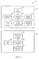
- FIG. 2 is a schematic diagram of a wireless charging system 20 according to an example of the present invention.
- the wireless charging system 20 includes a power transmitter 200 and a power receiver 220.
- the power transmitter 200 may be the power transmitter 100 shown in FIG. 1
- the power receiver 220 may be the power receiver 120 shown in FIG. 1 .
- the power transmitter 200 may include a power supply controller 202 and a wireless power transmitting unit 204.
- the power supply controller 202 such as a microcontroller or an Application Specific Integrated Circuit (ASIC), generally handles signals transmitted/received from the power receiver 200, so as to control the wireless power transmitted by the wireless power transmitting unit 204.
- ASIC Application Specific Integrated Circuit
- the power receiver 220 may include a processing means 222 such as a microprocessor or an ASIC, a wireless power receiving unit 224, a battery unit 226, a communication interface 228, a user interface 230, a program interface 232, and an interruption detecting unit 234.
- the wireless power receiving unit 224 receives the wireless power from the power transmitter 200 to charge the battery unit 226.
- the communication interface 228 is preferably a radio transceiver that transmits and receives radio signals (e.g., messages, emails, or packets) according to processing results of the processing means 222.
- the communication channel between the power transmitter 200 and the power receiver 220 may be an in-band communication channel (e.g. by using load modulation), in which communication signals are carried by the wireless power.
- the communication channel between the power transmitter 200 and the power receiver 220 may be an out-band communication channel (e.g. by using a short-range communication protocol such as Bluetooth).
- the user interface 230 may include a touch panel, keyboard, button, microphone, camera, fingerprint identity sensor, a gesture sensor, or any interface that can receive user inputs.
- the program interface 232 may be an application program interface, which receives a command or a control signal from the processing means 222 to launch a function or control an application provided by the power receiver 220.
- the interruption detecting unit 234 may be coupled to the power receiving unit 224 for real-time detecting whether the wireless power received by the power receiving unit 224 is interrupted.
- FIG. 3 is a flowchart of a process 30 according to an example of the present invention.
- the process 30 is utilized for a wireless charging system, such as the wireless charging system 20 shown in FIG. 2 , to protect a power receiver from being taken without permission while charged wirelessly and thus improve the security of the power receiver.
- the power receiver could be the power receiver 220 in the wireless charging system 20, but is not limited herein.
- the process 30 may be implemented by the power receiver 220 and compiled into a program code to instruct the processing means 222 to execute the following steps:
- an owner of the power receiver 220 may configure the power receiver 220 to perform wireless charging in the security mode.
- the owner may define a specific contour or drawing, a snapshot, a series of numbers and/or alphabets and/or symbols, a voice message including specific words or sentences, a gesture, a fingerprint, an image of a human face or a part of the body, or any of their combinations as the security code of the security mode.
- the interruption detecting unit 234 continuously detects whether the wireless power is interrupted (i.e. the power receiver 220 is removed from the power transmission coverage of the power transmitter 200) and generates a detection result for the processing means 222.
- the processing means 222 determines that an unauthorized interruption occurs and the power receiver 220 might be stolen.
- the power receiver 200 may start the protection function as an action to protect the power receiver 220 from being taken without permission.
- the protection function may be a function for releasing a warning signal to notify an owner of a power receiver theft.
- the warning signal may be in a form of a beep, a noisy sound, video, audio, image, and/or a bright light which is activated via the program interface 232 to draw the owner's attention.
- the present invention can prevent the charging receiver 220 from being taken without permission in a public space.
- the process 30 is an example of the present invention.
- the power receiver 220 may also launch a function or an application for reporting a location of the power receiver 220 through the program interface 232. In this way, the owner may track the lost power receiver 220 and manage to find it easily.
- another function or application may automatically send a loss notification to a specific person and/or a place for help.
- the example of the loss notification may be a message or an email sent via the communication interface 228.
- the example of the specific person and/or the place may be the owner of the power receiver 220, an owner who provided the power transmitter 200 such as a coffee shop or an airport, the front desk of the coffee shop, or a police station nearby.
- the power transmitter may have the capability to warn the owner about the power receiver theft as well.
- FIG. 4 is a schematic diagram of a wireless charging system 40 according to an example of the present invention.
- the wireless charging system 40 includes a power transmitter 400 and a power receiver 420.
- the power transmitter 400 may additionally include an output unit 406 and/or a communication interface 408.
- the output unit 406 may include a speaker, a light-emitted diode (LED), a screen, or a vibrator.
- the communication interface 408 may be a radio transceiver that can transmit and receive radio signals (e.g., messages, emails, or packets) according to a control signal of the power supply controller 402.
- FIG. 5A is a flowchart of a process 50A according to an example of the present invention.
- the process 50A is utilized for a wireless charging system, such as the wireless charging system 40 shown in FIG. 4 , to protect a power receiver from being taken without permission while charged wirelessly and thus improve the security of the power receiver.
- the power receiver could be the power receiver 420 in the wireless charging system 40, but is not limited herein.
- the process 50A may be implemented by the power receiver 420 and compiled into a program code to instruct the processing means 422 to execute the following steps:
- FIG. 5B is a flowchart of a process 50B according to an example of the present invention.
- the process 50B is the corresponding actions of the process 50A for the power transmitter 400.
- the process 50B may be implemented by the power supply controller 402 of the power transmitter 400 to execute the following steps:
- an owner of the power receiver 420 may configure the power receiver 420 to perform wireless charging in the security mode.
- the owner may define a specific contour or drawing, a snapshot, a series of numbers and/or alphabets and/or symbols, a voice message including specific words or sentences, a gesture, a fingerprint, an image of a human face or a part of the body, or any of their combinations as the security code of the security mode.
- the interruption detecting unit 434 continuously detects whether the wireless power is interrupted (i.e. the power receiver 420 is removed from the power transmission coverage of the power transmitter 400) and generates a detection result for the processing means 422.
- the processing means 222 may send an unauthorized interruption notification signal to the power transmitter 400.
- the power transmitter 400 or both the power transmitter 400 and the power receiver 420, can determine that an unauthorized interruption occurs and the power receiver 420 might be stolen, thereby starting the protection function such as releasing a warning signal in a form of a beep, a noisy sound, video, audio, image, and/or a bright light to draw the owner's attention.
- the power receiver 420 may also launch a function or an application for reporting a location of the power receiver 420 for searching the lost power receiver 420.
- the power transmitter 400 and/or the power receiver 420 may send a loss notification (e.g. a message or an email) to a specific person (e.g. the owner of the power receiver 420, an owner or the front desk of a place where the power transmitter 400 is provided such as a coffee shop, a train station, a restaurant or an airport) and/or a place (e.g. a police station nearby) for help via the communication interface 408/428.
- a loss notification e.g. a message or an email
- a specific person e.g. the owner of the power receiver 420, an owner or the front desk of a place where the power transmitter 400 is provided such as a coffee shop, a train station, a restaurant or an airport
- a place e.g. a police station nearby
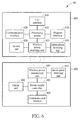
- FIG. 6 is a schematic diagram of a wireless charging system 60 according to an example of the present invention.
- the wireless charging system 60 includes a power transmitter 600 and a power receiver 620. Comparing to the wireless charging system 40 shown in FIG. 4 , the power transmitter 600 additionally includes an interruption detecting unit 610 and the power receiver 620 is not necessarily to include an interruption detecting unit.
- the power transmitter 600 may transmit wireless power to the power receiver 620 for wireless charging, and constantly detect whether the wireless charging is interrupted. If the power transmitter 600 detects that the wireless charging is interrupted, it start may a protection function so as to protect the power receiver 220 from being taken without permission.
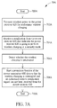
- FIG. 7A is a flowchart of a process 70A according to an example of the present invention.
- the process 70A is utilized for a wireless charging system, such as the wireless charging system 60 shown in FIG. 6 , to protect a power receiver from being taken without permission while charged wirelessly and thus improve the security of the power receiver.
- the power receiver could be the power receiver 620 in the wireless charging system 60, but is not limited herein.
- the process 70A may be implemented by the power supply controller 602 of the power transmitter 600 to execute the following steps:
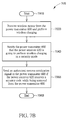
- FIG. 7B is a flowchart of a process 70B according to an example of the present invention.
- the process 70B is the corresponding actions of the process 70A for the power receiver 620.
- the process 70B may be implemented by the power receiver 620 and compiled into a program code to instruct the processing means 622 to execute the following steps:
- an owner of the power receiver 620 may configure the power receiver 620 to perform wireless charging in the security mode.
- the owner may define a specific contour or drawing, a snapshot, a series of numbers and/or alphabets and/or symbols, a voice message including specific words or sentences, a gesture, a fingerprint, an image of a human face or a part of the body, or their combination as the security code of the security mode.
- the power receiver 620 may notify the power transmitter 600 that the power receiver 620 is going to perform the wireless charging in the security mode.
- the interruption detecting unit 610 constantly detects whether the wireless power is interrupted (i.e.
- the power receiver 620 is removed from the power transmission coverage of the power transmitter 600) and generates a detection result for power supply controller 602.
- the owner of the power receiver 620 intends to terminate the wireless charging, the owner enters the security code to unlock the security mode. Accordingly, the power receiver 620 may send an authorized remove notification signal to the power transmitter 600. If the detection result indicates that the wireless charging is interrupted and the power transmitter 600 receives the authorized remove notification signal, the power supply controller 602 determines that the power receiver 620 is removed with permission. Otherwise, if the detection result indicates that the wireless charging is interrupted but the power transmitter 600 has not receive the authorized remove notification signal from the power receiver 620 within a certain period (e.g. 4 seconds), the power supply controller 602 determines that the unauthorized interruption occurs.
- a certain period e.g. 4 seconds
- the power transmitter 400 may determine that the power receiver 620 might be stolen, and therefore, start a protection function such as releasing the warning signal to draw the owner's attention and/or sending a loss notification (e.g. a message or an email) to a specific person to find help.
- a protection function such as releasing the warning signal to draw the owner's attention and/or sending a loss notification (e.g. a message or an email) to a specific person to find help.
- the power receiver 620 may constantly send a feedback to the power transmitter 600. Accordingly, the power transmitter 600 may detect that the wireless charging is interrupted if not receiving the feedback for more than a specific time. The feedback may be sent periodically or non-periodically. The feedback may be included in a control error packet (CEP) for sending to the power transmitter 600 during wireless charging.
- CEP control error packet
- the power receiver 620 may notify the power transmitter 600 that the power receiver 620 is going to perform the wireless charging in the security mode by a bit included in a configuration packet, during an identification and configuration phase which is a period for initializing the wireless charging.
- FIG. 8 illustrates a schematic diagram for a configuration packet 80 according to an example of the present invention. As shown in FIG. 8 , the configuration packet 80 includes a bit 800 which notifies the power transmitter 600 that the power receiver 620 is going to perform the wireless charging in the security mode.
- the authorized remove notification signal may be realized by an end power transfer packet with a message code indicating that the power receiver 620 is removed with authorization.
- FIG. 9 illustrates a schematic diagram for an end power transfer packet 90 according to an example of the present invention. As shown in FIG. 9 , the end power transfer packet 90 is defined with a specific message code (e.g., 0x0B or else) to indicate that the power receiver 620 is removed with authorization.
- a specific message code e.g., 0x0B or else
- the owner of the power receiver 620 may set the power receiver 620 on the power transmitter 600 before configuring the power receiver 620 to perform wireless charging in the security mode.
- the configuration packet 80 may have been sent to the power transmitter 600 already, so the power receiver 620 may send an end power transfer packet with a message code indicating 'Re-configure' and then send the configuration packet 80 for notifying the power transmitter 600 that the security mode is going to used.
- the owner can replace the power receiver 620 on the power transmitter 600.
- the power receiver 620 may send an identification packet to the power transmitter 600. If the power transmitter 600 finds that the identity if the replaced power receiver 620 is consistent with the previous one before the interruption, it may stop the protection functions.
- the power transmitter 600 may send an unauthorized interruption notification signal to the power receiver 620 after detecting the unauthorized interruption. Therefore, the power receiver 620, or both the power transmitter 600 and the power receiver 620, may determine that the power receiver 620 might be stolen, thereby activating the protection functions (e.g. releasing a warning signal to notify an owner of a power receiver theft, launching a function for reporting a location of the power receiver, and/or sending a message to a specific person or a place for help).
- the protection functions e.g. releasing a warning signal to notify an owner of a power receiver theft, launching a function for reporting a location of the power receiver, and/or sending a message to a specific person or a place for help.
- the abovementioned steps of the processes 30, 50A, 50B, 70A, and 70B including suggested steps may be realized by means of hardware, software, firmware, or an electronic system.
- Examples of hardware may include analog, digital and mixed circuits known as microcircuit, microchip, or silicon chip.
- Examples of the electronic system may include a system on chip (SOC), system in package (SiP), and a computer on module (COM).
- SOC system on chip
- SiP system in package
- COM computer on module
- the present invention provides a security mode (i.e. in addition to a normal charging mode) for charging in a public space.
- a security mode i.e. in addition to a normal charging mode
- the protection functions such as releasing the warning signal, sending a loss notification, and functions to track the power receiver are activated, thus preventing the power receiver from being stolen.
Landscapes
- Engineering & Computer Science (AREA)
- Computer Hardware Design (AREA)
- Theoretical Computer Science (AREA)
- Physics & Mathematics (AREA)
- General Physics & Mathematics (AREA)
- Computer Networks & Wireless Communication (AREA)
- Power Engineering (AREA)
- Computer Security & Cryptography (AREA)
- Software Systems (AREA)
- General Engineering & Computer Science (AREA)
- Charge And Discharge Circuits For Batteries Or The Like (AREA)
- Telephone Function (AREA)
Description
- The present invention relates to a method used in a wireless charging system and related wireless charging device, and more particularly, to a method of improving the security of the power receiver in a wireless charging system and related wireless charging device.
- With the proliferation of portable electronic devices such as smart phone and tablet PC, the demand for charging devices, especially for those provided in public areas, is increasing. In addition, people would like to get rid of annoying wires if possible. One technology which realizes this desire is wireless charging, in which mobile device(s) (i.e. power receiver) is placed on and charged through a charging device (i.e. power transmitter). Therefore, the current trend is towards providing wireless charging in public areas so that people can easily find a wireless power supply to charge their portable electronic devices.
- Wireless Power Consortium (WPC) is a leading organization in the world to define wireless charging specification. The document Wireless Power Transfer - Volume I, part I in version 1.1.1 released in July 2012 has specified the communication protocol between a power transmitter and a power receiver. In section 5.3.3, it defines that the power receiver shall transmit the following sequence of packets:
- 1. An Identification Packet, which includes an identity of the power receiver if the power receiver enters an identification and configuration phase from the ping phase.
- 2. An Extended Identification Packet, if the Ext bit of the preceding Identification Packet is set to ONE.
- 3. Up to 7 Optional Configuration Packets.
- 4. A Configuration Packet, where the second byte (B1) and the fifth byte (B4) of the Configuration Packet are reserved bytes, and the 4 bits (b6-b3) in the third byte (B2) are reserved bits.
- On the other hand, the specification defines that the power receiver shall transmit zero or more of the Control Error Packet, the Received Power Packet, the Charge Status Packet, the End Power Transfer Packet, and Any Proprietary Packet. If the power transmitter does not know how to handle the message contained in the Proprietary Packet, the power transmitter shall ignore that message.
- Furthermore, the specification defines that at any time a user can remove a Mobile Device that is receiving power. The power transmitter can recognize such an event from a time-out in the communications from the power receiver or from a violation of the Power Transfer Contract. In addition, the power receiver may stop transmitting packets to the power transmitter at any time.
- From the above description, the specification defines that the Identification Packet is sent from Power Receiver to the power transmitter only once at the identification and configuration phase, and it supports to remove the power receiver at any time. But how the power transmitter knows the power receiver is removed by the owner or by the others is not sure. As people place their mobile devices on a power transmitter, they may not always keep an eye on them. In such a situation, the mobile devices might be taken away by other people without permission.
- Therefore, how to secure the power receiver while the power receiver performs wireless charging publicly is a topic to be addressed and discussed in the industry.
EP 2 620 889 A1 forms part of the prior art pursuant to Art. 54 (3) EPC and discloses a battery powered electronic device which is protected from being stolen in connection with battery charging. A method comprises establishing a connection with an electric charging device, entering a locked mode of operation, where the locked mode of operation comprises monitoring an existence of an unlock signal and monitoring an existence of the connection with the electric charging device, and performing a protective action in response to a non-existence of the signaling connection and a non-existence of the unlock signal.
GB 2 320 397 A
US 2007/279002 A1 discloses a power source, charging system, and inductive receiver for mobile devices. A pad or similar base unit comprises a primary, which creates a magnetic field by applying an alternating current to a winding, coil, or any type of current carrying wire. A receiver comprises a means for receiving the energy from the alternating magnetic field and transferring it to a mobile or other device. The receiver can also comprise electronic components or logic to set the voltage and current to the appropriate levels required by the mobile device, or to communicate information or data to and from the pad. The system may also incorporate efficiency measures that improve the efficiency of power transfer between the charger and receiver. - An objective of the present invention is to provide a method and related wireless charging system capable of protecting the power receiver from being taken without permission.
- The present invention discloses a method for a power receiver for protecting the power receiver from being taken without permission while charged wirelessly, as set forth in claim 1.
- The present invention further discloses a method for a power transmitter for protecting a power receiver from being taken without permission while charged wirelessly, as set forth in claim 5.
Preferred embodiments of the present invention may be gathered from the dependent claims.
These and other objectives of the present invention will no doubt become obvious to those of ordinary skill in the art after reading the following detailed description of the preferred embodiment that is illustrated in the various figures and drawings. -
-
FIG. 1 is a schematic diagram of a wireless charging system according to an example of the present invention. -
FIG. 2 is a schematic diagram of a wireless charging system according to an example of the present invention. -
FIG. 3 is a flowchart of a process according to an example of the present invention. -
FIG. 4 is a schematic diagram of a wireless charging system according to an example of the present invention. -
FIG. 5A is a flowchart of a process according to an example of the present invention. -
FIG. 5B is a flowchart of a process according to an example of the present invention. -
FIG. 6 is a schematic diagram of a wireless charging system according to an example of the present invention. -
FIG. 7A is a flowchart of a process according to an example of the present invention. -
FIG. 7B is a flowchart of a process according to an example of the present invention. -
FIG. 8 is a schematic diagram of a configuration packet according to an example of the present invention. -
FIG. 9 is a schematic diagram of an end power transfer packet according to an example of the present invention. - Please refer to
FIG. 1 , which illustrates a schematic diagram of awireless charging system 10 according to an example of the present disclosure. A wireless charging system may include at least one power transmitter and at least one power receiver. For simplicity, inFIG. 1 , thewireless charging system 10 is briefly composed of apower transmitter 100 and apower receiver 120. The power transmitter may represent a power base station, or a power transmitting module including digital/analog chip(s), to supply wireless power. The power receiver may be a mobile phone, a laptop, a tablet computer, an electronic book, a portable computer system, any other mobile devices or at least a power receiving module. Alternatively, thepower receiver 120 may be any electronic device using battery as its power supply, such as a wearable computing device, a wearable medical device, a portable MP3 player, etc. Thepower receiver 120 may directly attach to thepower transmitter 100 or keep within a distance from thepower transmitter 100 for wireless charging. As shown inFIG. 1 , thepower receiver 120 receives wireless power from thepower transmitter 100 by electromagnetic induction, so as to charge the battery of thepower receiver 120 without using any wire connection. - Please refer to
FIG. 2 , which is a schematic diagram of awireless charging system 20 according to an example of the present invention. Thewireless charging system 20 includes apower transmitter 200 and apower receiver 220. Thepower transmitter 200 may be thepower transmitter 100 shown inFIG. 1 , and thepower receiver 220 may be thepower receiver 120 shown inFIG. 1 . Thepower transmitter 200 may include apower supply controller 202 and a wirelesspower transmitting unit 204. Thepower supply controller 202, such as a microcontroller or an Application Specific Integrated Circuit (ASIC), generally handles signals transmitted/received from thepower receiver 200, so as to control the wireless power transmitted by the wirelesspower transmitting unit 204. Thepower receiver 220 may include a processing means 222 such as a microprocessor or an ASIC, a wirelesspower receiving unit 224, abattery unit 226, acommunication interface 228, auser interface 230, aprogram interface 232, and aninterruption detecting unit 234. The wirelesspower receiving unit 224 receives the wireless power from thepower transmitter 200 to charge thebattery unit 226. Thecommunication interface 228 is preferably a radio transceiver that transmits and receives radio signals (e.g., messages, emails, or packets) according to processing results of the processing means 222. In addition, the communication channel between thepower transmitter 200 and thepower receiver 220 may be an in-band communication channel (e.g. by using load modulation), in which communication signals are carried by the wireless power. Alternatively, the communication channel between thepower transmitter 200 and thepower receiver 220 may be an out-band communication channel (e.g. by using a short-range communication protocol such as Bluetooth). Theuser interface 230 may include a touch panel, keyboard, button, microphone, camera, fingerprint identity sensor, a gesture sensor, or any interface that can receive user inputs. Theprogram interface 232 may be an application program interface, which receives a command or a control signal from the processing means 222 to launch a function or control an application provided by thepower receiver 220. Theinterruption detecting unit 234 may be coupled to thepower receiving unit 224 for real-time detecting whether the wireless power received by thepower receiving unit 224 is interrupted. - Please refer to
FIG. 3 , which is a flowchart of a process 30 according to an example of the present invention. The process 30 is utilized for a wireless charging system, such as thewireless charging system 20 shown inFIG. 2 , to protect a power receiver from being taken without permission while charged wirelessly and thus improve the security of the power receiver. The power receiver could be thepower receiver 220 in thewireless charging system 20, but is not limited herein. The process 30 may be implemented by thepower receiver 220 and compiled into a program code to instruct the processing means 222 to execute the following steps: - Step 300: Start.
- Step 302: Receive wireless power from the
power transmitter 200 and perform wireless charging in a security mode. - Step 304: Detect whether the wireless charging is interrupted without receiving a security code for authorization.
- Step 306: Start a protection function if the
power receiver 220 detects that the wireless charging is interrupted without receiving a security code for authorization. - Step 308: End.
- According to the process 30, an owner of the
power receiver 220 may configure thepower receiver 220 to perform wireless charging in the security mode. The owner may define a specific contour or drawing, a snapshot, a series of numbers and/or alphabets and/or symbols, a voice message including specific words or sentences, a gesture, a fingerprint, an image of a human face or a part of the body, or any of their combinations as the security code of the security mode. When thepower receiving unit 224 performs wireless charging, theinterruption detecting unit 234 continuously detects whether the wireless power is interrupted (i.e. thepower receiver 220 is removed from the power transmission coverage of the power transmitter 200) and generates a detection result for the processing means 222. If the detection result indicates that the wireless charging is interrupted but a user input matching with the security code has not been received within a certain period (e.g. 5 seconds), the processing means 222 determines that an unauthorized interruption occurs and thepower receiver 220 might be stolen. In response, thepower receiver 200 may start the protection function as an action to protect thepower receiver 220 from being taken without permission. For example, the protection function may be a function for releasing a warning signal to notify an owner of a power receiver theft. The warning signal may be in a form of a beep, a noisy sound, video, audio, image, and/or a bright light which is activated via theprogram interface 232 to draw the owner's attention. As a result, the present invention can prevent the chargingreceiver 220 from being taken without permission in a public space. - Note that the process 30 is an example of the present invention. Those skilled in the art should readily make combinations, modifications and/or alterations on the abovementioned description and examples. For example, after the unauthorized interruption is detected, the
power receiver 220 may also launch a function or an application for reporting a location of thepower receiver 220 through theprogram interface 232. In this way, the owner may track the lostpower receiver 220 and manage to find it easily. In addition, another function or application may automatically send a loss notification to a specific person and/or a place for help. The example of the loss notification may be a message or an email sent via thecommunication interface 228. The example of the specific person and/or the place may be the owner of thepower receiver 220, an owner who provided thepower transmitter 200 such as a coffee shop or an airport, the front desk of the coffee shop, or a police station nearby. - In another example, the power transmitter may have the capability to warn the owner about the power receiver theft as well. Please refer to
FIG. 4 , which is a schematic diagram of awireless charging system 40 according to an example of the present invention. Thewireless charging system 40 includes apower transmitter 400 and apower receiver 420. Comparing to thewireless charging system 20 shown inFIG. 2 , thepower transmitter 400 may additionally include anoutput unit 406 and/or acommunication interface 408. Theoutput unit 406 may include a speaker, a light-emitted diode (LED), a screen, or a vibrator. Thecommunication interface 408 may be a radio transceiver that can transmit and receive radio signals (e.g., messages, emails, or packets) according to a control signal of thepower supply controller 402. - Please refer to
FIG. 5A , which is a flowchart of aprocess 50A according to an example of the present invention. Theprocess 50A is utilized for a wireless charging system, such as thewireless charging system 40 shown inFIG. 4 , to protect a power receiver from being taken without permission while charged wirelessly and thus improve the security of the power receiver. The power receiver could be thepower receiver 420 in thewireless charging system 40, but is not limited herein. Theprocess 50A may be implemented by thepower receiver 420 and compiled into a program code to instruct the processing means 422 to execute the following steps: -
Step 500A: Start. -
Step 502A: Receive wireless power from thepower transmitter 400 and perform wireless charging in a security mode. -
Step 504A: Detect whether the wireless charging is interrupted without receiving a security code for authorization. -
Step 506A: Send an unauthorized interruption notification signal to thepower transmitter 400 after thepower receiver 420 detects that the wireless charging is interrupted without receiving the security code for authorization. -
Step 508A: End. - Please refer to
FIG. 5B , which is a flowchart of aprocess 50B according to an example of the present invention. Theprocess 50B is the corresponding actions of theprocess 50A for thepower transmitter 400. Theprocess 50B may be implemented by thepower supply controller 402 of thepower transmitter 400 to execute the following steps: -
Step 500B: Start. -
Step 502B: Transmit wireless power to thepower receiver 420. -
Step 504B: Start a protection function after the unauthorized interruption notification signal is received. -
Step 506B: End. - According to the
processes power receiver 420 may configure thepower receiver 420 to perform wireless charging in the security mode. The owner may define a specific contour or drawing, a snapshot, a series of numbers and/or alphabets and/or symbols, a voice message including specific words or sentences, a gesture, a fingerprint, an image of a human face or a part of the body, or any of their combinations as the security code of the security mode. When thepower receiving unit 424 performs wireless charging, theinterruption detecting unit 434 continuously detects whether the wireless power is interrupted (i.e. thepower receiver 420 is removed from the power transmission coverage of the power transmitter 400) and generates a detection result for the processing means 422. If the detection result indicates that the wireless charging is interrupted but a user input matching with the security code has not been received within a certain period (e.g. 5 seconds), the processing means 222 may send an unauthorized interruption notification signal to thepower transmitter 400. In such a situation, thepower transmitter 400, or both thepower transmitter 400 and thepower receiver 420, can determine that an unauthorized interruption occurs and thepower receiver 420 might be stolen, thereby starting the protection function such as releasing a warning signal in a form of a beep, a noisy sound, video, audio, image, and/or a bright light to draw the owner's attention. - In addition, the
power receiver 420 may also launch a function or an application for reporting a location of thepower receiver 420 for searching the lostpower receiver 420. Furthermore, thepower transmitter 400 and/or thepower receiver 420 may send a loss notification (e.g. a message or an email) to a specific person (e.g. the owner of thepower receiver 420, an owner or the front desk of a place where thepower transmitter 400 is provided such as a coffee shop, a train station, a restaurant or an airport) and/or a place (e.g. a police station nearby) for help via thecommunication interface 408/428. - In another example, the unauthorized interruption is detected by a power transmitter. Please refer to
FIG. 6 , which is a schematic diagram of awireless charging system 60 according to an example of the present invention. Thewireless charging system 60 includes apower transmitter 600 and apower receiver 620. Comparing to thewireless charging system 40 shown inFIG. 4 , thepower transmitter 600 additionally includes aninterruption detecting unit 610 and thepower receiver 620 is not necessarily to include an interruption detecting unit. In this example, thepower transmitter 600 may transmit wireless power to thepower receiver 620 for wireless charging, and constantly detect whether the wireless charging is interrupted. If thepower transmitter 600 detects that the wireless charging is interrupted, it start may a protection function so as to protect thepower receiver 220 from being taken without permission. - Please refer to
FIG. 7A , which is a flowchart of aprocess 70A according to an example of the present invention. Theprocess 70A is utilized for a wireless charging system, such as thewireless charging system 60 shown inFIG. 6 , to protect a power receiver from being taken without permission while charged wirelessly and thus improve the security of the power receiver. The power receiver could be thepower receiver 620 in thewireless charging system 60, but is not limited herein. Theprocess 70A may be implemented by thepower supply controller 602 of thepower transmitter 600 to execute the following steps: -
Step 700A: Start. -
Step 702A: Transmit wireless power to thepower receiver 620 for performing wireless charging. - Step 704A: Receive a notification from the
power receiver 620 that indicates thepower receiver 620 is going to perform wireless charging in a security mode. -
Step 706A: Detect whether the wireless charging is interrupted. -
Step 708A: Start a protection function if thepower transmitter 600 detects that the wireless charging is interrupted and an authorized remove notification signal has not been received from thepower receiver 620. -
Step 710A: End. - Please refer to
FIG. 7B , which is a flowchart of aprocess 70B according to an example of the present invention. Theprocess 70B is the corresponding actions of theprocess 70A for thepower receiver 620. Theprocess 70B may be implemented by thepower receiver 620 and compiled into a program code to instruct the processing means 622 to execute the following steps: -
Step 700B: Start. -
Step 702B: Receive wireless power from thepower transmitter 600 and perform wireless charging. -
Step 704B: Notify thepower transmitter 600 that thepower receiver 620 is going to perform wireless charging in a security mode. -
Step 706B: Send an authorized remove notification signal to thepower transmitter 600 if thepower receiver 620 receives a security code while being removed from thepower transmitter 600. -
Step 708B: End. - According to the
processes power receiver 620 may configure thepower receiver 620 to perform wireless charging in the security mode. The owner may define a specific contour or drawing, a snapshot, a series of numbers and/or alphabets and/or symbols, a voice message including specific words or sentences, a gesture, a fingerprint, an image of a human face or a part of the body, or their combination as the security code of the security mode. During performing wireless charging, thepower receiver 620 may notify thepower transmitter 600 that thepower receiver 620 is going to perform the wireless charging in the security mode. When the wirelesspower transmitting unit 604 transmits wireless power, theinterruption detecting unit 610 constantly detects whether the wireless power is interrupted (i.e. thepower receiver 620 is removed from the power transmission coverage of the power transmitter 600) and generates a detection result forpower supply controller 602. On the other hand, when the owner of thepower receiver 620 intends to terminate the wireless charging, the owner enters the security code to unlock the security mode. Accordingly, thepower receiver 620 may send an authorized remove notification signal to thepower transmitter 600. If the detection result indicates that the wireless charging is interrupted and thepower transmitter 600 receives the authorized remove notification signal, thepower supply controller 602 determines that thepower receiver 620 is removed with permission. Otherwise, if the detection result indicates that the wireless charging is interrupted but thepower transmitter 600 has not receive the authorized remove notification signal from thepower receiver 620 within a certain period (e.g. 4 seconds), thepower supply controller 602 determines that the unauthorized interruption occurs. In such a situation, thepower transmitter 400 may determine that thepower receiver 620 might be stolen, and therefore, start a protection function such as releasing the warning signal to draw the owner's attention and/or sending a loss notification (e.g. a message or an email) to a specific person to find help. - In an example, the
power receiver 620 may constantly send a feedback to thepower transmitter 600. Accordingly, thepower transmitter 600 may detect that the wireless charging is interrupted if not receiving the feedback for more than a specific time. The feedback may be sent periodically or non-periodically. The feedback may be included in a control error packet (CEP) for sending to thepower transmitter 600 during wireless charging. - In an example, the
power receiver 620 may notify thepower transmitter 600 that thepower receiver 620 is going to perform the wireless charging in the security mode by a bit included in a configuration packet, during an identification and configuration phase which is a period for initializing the wireless charging.FIG. 8 illustrates a schematic diagram for aconfiguration packet 80 according to an example of the present invention. As shown inFIG. 8 , theconfiguration packet 80 includes abit 800 which notifies thepower transmitter 600 that thepower receiver 620 is going to perform the wireless charging in the security mode. - The authorized remove notification signal may be realized by an end power transfer packet with a message code indicating that the
power receiver 620 is removed with authorization.FIG. 9 illustrates a schematic diagram for an endpower transfer packet 90 according to an example of the present invention. As shown inFIG. 9 , the endpower transfer packet 90 is defined with a specific message code (e.g., 0x0B or else) to indicate that thepower receiver 620 is removed with authorization. - In another example, the owner of the
power receiver 620 may set thepower receiver 620 on thepower transmitter 600 before configuring thepower receiver 620 to perform wireless charging in the security mode. Under this condition, theconfiguration packet 80 may have been sent to thepower transmitter 600 already, so thepower receiver 620 may send an end power transfer packet with a message code indicating 'Re-configure' and then send theconfiguration packet 80 for notifying thepower transmitter 600 that the security mode is going to used. - If the owner takes the
power receiver 620 away from thepower transmitter 600 without entering the security code of the security mode and thus induces the protection functions (e.g. releasing the warning signal, sending a loss notification, or reporting the location of the power receiver 620) of thewireless charging system 60, the owner can replace thepower receiver 620 on thepower transmitter 600. In such a situation, thepower receiver 620 may send an identification packet to thepower transmitter 600. If thepower transmitter 600 finds that the identity if the replacedpower receiver 620 is consistent with the previous one before the interruption, it may stop the protection functions. - In another example, the
power transmitter 600 may send an unauthorized interruption notification signal to thepower receiver 620 after detecting the unauthorized interruption. Therefore, thepower receiver 620, or both thepower transmitter 600 and thepower receiver 620, may determine that thepower receiver 620 might be stolen, thereby activating the protection functions (e.g. releasing a warning signal to notify an owner of a power receiver theft, launching a function for reporting a location of the power receiver, and/or sending a message to a specific person or a place for help). - The abovementioned steps of the
processes - To sum up, the present invention provides a security mode (i.e. in addition to a normal charging mode) for charging in a public space. After the unauthorized interruption of the wireless charging is detected, the protection functions such as releasing the warning signal, sending a loss notification, and functions to track the power receiver are activated, thus preventing the power receiver from being stolen.
Those skilled in the art will readily observe that numerous modifications and alterations of the device and method may be made while retaining the teachings of the invention. Accordingly, the above disclosure should be construed as limited only by the metes and bounds of the appended claims.
Claims (12)
- A method for a power receiver (120, 220, 420, 620) for protecting the power receiver (120, 220, 420, 620) from being taken without permission while charged wirelessly, the method comprising:receiving (302) wireless power from a power transmitter (100, 200, 400, 600) and performing wireless charging in a security mode by the power receiver (120, 220, 420, 620);constantly transmitting a feedback to the power transmitter (100, 200, 400, 600) so as to enable the power transmitter (100, 200, 400, 600) to determine (706A) that the wireless charging is interrupted when the power transmitter (100, 200, 400, 600) does not receive the feedback for more than a specific time, wherein the feedback is included in a control error packet, CEP, for sending to the power transmitter (100, 200, 400, 600) during wireless charging, and wherein the feedback is sent periodically or non-periodically; anddetecting (304)whether the wireless charging is interrupted without receiving a security code for authorization;starting (306) a protection function if the power receiver (120, 220, 420, 620) detects that the wireless charging is interrupted without receiving the security code for authorization.
- The method of claim 1, wherein the protection function comprises at least one of releasing a warning signal to notify an owner of a power receiver theft, launching a function for reporting a location of the power receiver (120, 220, 420, 620), and sending a message to a specific person or a place for help.
- The method of claim 1, further comprising:sending an unauthorized interruption notification signal to the power transmitter (100, 200, 400, 600) after detecting that the wireless charging is interrupted without receiving the security code for authorization.
- The method of claim 3, wherein the power transmitter (100, 200, 400, 600) releases a warning signal to notify an owner of a power receiver theft or sends a message to a specific person or a place for help after receiving the unauthorized interruption notification signal.
- A method for a power transmitter (100, 200, 400, 600) for protecting a power receiver (120, 220, 420, 620) from being taken without permission while charged wirelessly, the method comprising:transmitting (702A) wireless power to the power receiver (120, 220, 420, 620) for wireless charging by a power transmitter (100, 200, 400, 600);constantly receiving a feedback from the power receiver (120, 220, 420, 620), wherein the feedback is included in a control error packet, CEP, for receiving by the power transmitter (100, 200, 400, 600) during wireless charging, and wherein the feedback is sent periodically or non-periodically;detecting (706A) whether the wireless charging is interrupted by determining that the wireless charging is interrupted when the power transmitter (100, 200, 400, 600) does not receive the feedback for more than a specific time; andstarting (708A) a protection function if the power transmitter (100, 200, 400, 600) detects that the wireless charging is interrupted and an authorized remove notification signal has not been received from the power receiver (120, 220, 420, 620).
- The method of claim 5, further comprising:receiving (704A) a notification from the power receiver (120, 220, 420, 620) indicating that the power receiver (120, 220, 420, 620) is going to perform wireless charging in a security mode.
- The method of claim 6, wherein the notification is realized by a bit included in the configuration packet transmitted to the power transmitter (100, 200, 400, 600), for notifying that the power receiver (120, 220, 420, 620) is going to perform the wireless charging in the security mode.
- The method of claim 5, wherein the authorized remove notification signal is received via an end power transfer packet with a message code indicating that the power receiver (120, 220, 420, 620) is removed with authorization.
- The method of claim 5 , wherein the protection function comprises releasing a warning signal to notify an owner of a power receiver theft, or sending a message to a specific person or a place for help.
- The method of claim 5, further comprising:sending an unauthorized interruption notification signal to the power receiver (120, 220, 420, 620) after detecting that the wireless charging is interrupted.
- The method of claim 10, wherein the power receiver (120, 220, 420, 620) releases a warning signal to notify an owner of a power receiver theft, launches a function for reporting a location of the power receiver (120, 220, 420, 620), or sends a message to a specific person or a place for help after receiving the unauthorized interruption notification signal.
- The method of claim 5, further comprising:stopping the protection function after the power receiver (120, 220, 420, 620) is replaced on the power transmitter (100, 200, 400, 600) or after time-out.
Applications Claiming Priority (2)
| Application Number | Priority Date | Filing Date | Title |
|---|---|---|---|
| US201361768373P | 2013-02-22 | 2013-02-22 | |
| US201361834890P | 2013-06-14 | 2013-06-14 |
Publications (2)
| Publication Number | Publication Date |
|---|---|
| EP2770601A1 EP2770601A1 (en) | 2014-08-27 |
| EP2770601B1 true EP2770601B1 (en) | 2016-08-17 |
Family
ID=50189485
Family Applications (1)
| Application Number | Title | Priority Date | Filing Date |
|---|---|---|---|
| EP14020018.9A Active EP2770601B1 (en) | 2013-02-22 | 2014-02-24 | Method of protecting a power receiver |
Country Status (2)
| Country | Link |
|---|---|
| US (2) | US9507969B2 (en) |
| EP (1) | EP2770601B1 (en) |
Families Citing this family (11)
| Publication number | Priority date | Publication date | Assignee | Title |
|---|---|---|---|---|
| JP6349882B2 (en) * | 2014-03-31 | 2018-07-04 | 富士通株式会社 | Power receiving apparatus, information processing method, and information processing program |
| FR3029313B1 (en) * | 2014-12-01 | 2017-01-13 | Compagnie Ind Et Financiere Dingenierie Ingenico | METHOD FOR DETECTING MAIN CONNECTOR DISCONNECTION OF AN ELECTRONIC PAYMENT TERMINAL, COMPUTER PROGRAM PRODUCT, CORRESPONDING STORAGE MEDIUM AND PAYMENT TERMINAL |
| EP3136814B1 (en) * | 2015-08-24 | 2020-03-04 | GN Audio A/S | Apparatus and method for receiving an audio signal |
| JP6665568B2 (en) * | 2016-02-12 | 2020-03-13 | セイコーエプソン株式会社 | Control device, power receiving device, electronic device, power transmission system, and power supply method |
| CN115603473A (en) * | 2016-07-01 | 2023-01-13 | Lg伊诺特有限公司(Kr) | Method of communicating with wireless power transmitter and wireless power receiver |
| FR3061993B1 (en) * | 2017-01-17 | 2019-09-13 | Continental Automotive France | METHOD FOR CHARGING A BATTERY BY NEAR-FIELD COMMUNICATION |
| US20230123806A1 (en) | 2017-07-07 | 2023-04-20 | Neuroderm, Ltd. | Device for subcutaneous delivery of fluid medicament |
| JP7126544B2 (en) | 2017-07-07 | 2022-08-26 | ニューロダーム リミテッド | Vial adapter, method and filling system for filling a reservoir of a drug delivery device with a flowable drug using the vial adapter |
| CN108877062A (en) * | 2018-06-29 | 2018-11-23 | 深圳来电科技有限公司 | A kind of method, mobile terminal and server for renting wireless charging device |
| JP7278855B2 (en) * | 2019-04-24 | 2023-05-22 | キヤノン株式会社 | Power transmission device, control method executed by power transmission device, and program |
| CN110718972B (en) * | 2019-10-28 | 2021-08-13 | 清华-伯克利深圳学院筹备办公室 | Wireless automatic positioning charging method, device, equipment and storage medium |
Family Cites Families (39)
| Publication number | Priority date | Publication date | Assignee | Title |
|---|---|---|---|---|
| US5530431A (en) * | 1995-04-11 | 1996-06-25 | Wingard; Peter F. | Anti-theft device for protecting electronic equipment |
| JPH1051961A (en) * | 1996-07-31 | 1998-02-20 | Toshiba Corp | Short-circuit protective circuit for battery pack |
| GB2320397B (en) * | 1996-12-11 | 2001-11-07 | Nokia Mobile Phones Ltd | Portable electronic apparatus |
| US6111504A (en) * | 1999-01-12 | 2000-08-29 | Packard; Jeffrey W. | Electronic equipment security and recovery system |
| US6718381B1 (en) * | 1999-01-26 | 2004-04-06 | Dell Usa L.P. | Removal notification for a computer system |
| US6609207B1 (en) * | 1999-03-02 | 2003-08-19 | International Business Machines Corporation | Data processing system and method for securing a docking station and its portable PC |
| JP2002199062A (en) * | 2000-12-25 | 2002-07-12 | Hitachi Ltd | Portable terminal equipment |
| WO2002089081A1 (en) * | 2001-04-26 | 2002-11-07 | Caveo Technology, Llc | Pc card security system |
| AU2002950343A0 (en) * | 2002-07-24 | 2002-09-12 | Evatayhow Holdings Pty Ltd | Theft deterrence security system |
| GB2394843A (en) * | 2002-10-28 | 2004-05-05 | Zap Wireless Technologies Ltd | Charge and data transfer by the same means |
| US20040203601A1 (en) * | 2002-12-19 | 2004-10-14 | Morriss Matthew James | Method and apparatus for activating a restrictive operating mode of a wireless communication device |
| US20050104555A1 (en) | 2003-11-17 | 2005-05-19 | Phillip Simmonds-Short | Secure recharge station |
| US20070072474A1 (en) * | 2005-04-27 | 2007-03-29 | Nigel Beasley | Flexible power adapter systems and methods |
| US8539590B2 (en) * | 2005-12-20 | 2013-09-17 | Apple Inc. | Protecting electronic devices from extended unauthorized use |
| US7948208B2 (en) * | 2006-06-01 | 2011-05-24 | Mojo Mobility, Inc. | Power source, charging system, and inductive receiver for mobile devices |
| FI20065390L (en) * | 2006-06-08 | 2007-12-09 | Innohome Oy | Automatic multi-level access control system for electronic and electrical equipment |
| DE102006029427A1 (en) | 2006-06-27 | 2008-01-03 | Wolf-Dieter Freyhann | Charger for e.g. mobile telephone, has alarm function, which is switched on or off by code, where alarm is triggered, when socket and terminal of cable of charger are disconnected independent of whether charging process is completed or not |
| US20080141069A1 (en) * | 2006-12-06 | 2008-06-12 | Sony Electronics Inc. | Back-up supply for devce registration |
| US8312559B2 (en) * | 2007-01-26 | 2012-11-13 | Hewlett-Packard Development Company, L.P. | System and method of wireless security authentication |
| US20090128346A1 (en) * | 2007-11-20 | 2009-05-21 | Motorola, Inc. | Alert devices and methods for portable electronic device removal from chargers |
| US8103391B2 (en) * | 2008-08-19 | 2012-01-24 | International Business Machines Corporation | System for detecting interrupt conditions during an electric vehicle charging process |
| US20120150670A1 (en) | 2009-01-06 | 2012-06-14 | Access Business Group International Llc | Wireless power delivery during payment |
| WO2011014142A1 (en) * | 2009-07-30 | 2011-02-03 | Orna Vaknin | Public cellular telephone charging station |
| JP2011041409A (en) | 2009-08-12 | 2011-02-24 | Mobilelife Kk | Cellular phone battery charger with security function |
| US8346305B2 (en) * | 2009-09-25 | 2013-01-01 | Intel Corporation | Theft deterrent techniques and secure mobile platform subscription for wirelessly enabled mobile devices |
| US9125174B2 (en) * | 2010-03-25 | 2015-09-01 | Htc Corporation | Apparatuses and methods for selectively receiving multimedia broadcast/multicast service in a wireless communications system |
| DE102010039106A1 (en) * | 2010-08-10 | 2012-02-16 | Hilti Aktiengesellschaft | Hand tool with anti-theft device |
| US8587429B2 (en) * | 2010-08-25 | 2013-11-19 | Itron, Inc. | Device and method for switch-isolated power control of one or more communication devices |
| US8493226B2 (en) * | 2010-08-30 | 2013-07-23 | Brian Tedesco | Battery charger loss prevention adaptor having a notification module |
| CN102005108B (en) | 2010-11-23 | 2014-08-20 | 鸿富锦精密工业(深圳)有限公司 | Electronic device and method for transmitting warning messages timely and anti-theft monitoring system |
| US10043223B2 (en) * | 2010-12-30 | 2018-08-07 | International Business Machines Corporation | Managing power distribution |
| US8525688B2 (en) | 2011-01-10 | 2013-09-03 | Palm, Inc. | Proximity detection alarm for an inductively charged mobile computing device |
| US8946939B2 (en) * | 2011-03-31 | 2015-02-03 | Qualcomm Incorporated | Systems and methods for detecting and protecting a wireless power communication device in a wireless power system |
| JP5758051B2 (en) * | 2011-07-26 | 2015-08-05 | ゴゴロ インク | Apparatus, method, and article for physically ensuring a vehicle power storage device |
| US9551805B2 (en) * | 2011-10-13 | 2017-01-24 | Integrated Device Technology, Inc. | Apparatus, system, and method for detecting a foreign object in an inductive wireless power transfer system via coupling coefficient measurement |
| WO2013087971A1 (en) * | 2011-12-14 | 2013-06-20 | Nokia Corporation | Method and apparatus for optimizing standby power consumption and providing user indications in wpc based wireless charging system |
| WO2013087970A1 (en) * | 2011-12-14 | 2013-06-20 | Nokia Corporation | Method and apparatus for improving electronic devices wireless charging using inertial sensors |
| EP2620889A1 (en) | 2012-01-25 | 2013-07-31 | Sony Ericsson Mobile Communications AB | Theft protection |
| US9490649B2 (en) * | 2012-06-13 | 2016-11-08 | Toyota Motor Engineering & Manufacturing North America, Inc. | System and method for wireless charging |
-
2014
- 2014-02-24 US US14/188,656 patent/US9507969B2/en active Active
- 2014-02-24 EP EP14020018.9A patent/EP2770601B1/en active Active
-
2016
- 2016-10-27 US US15/335,437 patent/US9904812B2/en active Active
Also Published As
| Publication number | Publication date |
|---|---|
| US9904812B2 (en) | 2018-02-27 |
| US20170046541A1 (en) | 2017-02-16 |
| US20140245464A1 (en) | 2014-08-28 |
| EP2770601A1 (en) | 2014-08-27 |
| US9507969B2 (en) | 2016-11-29 |
Similar Documents
| Publication | Publication Date | Title |
|---|---|---|
| EP2770601B1 (en) | Method of protecting a power receiver | |
| US10122841B2 (en) | Smartphone proximity card emulation | |
| KR102147566B1 (en) | Apparatus, method and system for safely charging mobile devices | |
| KR101789540B1 (en) | Method for Wirelessly charging battery, Wireless charger, and electronic device | |
| CN103606211A (en) | Method, equipment and system used for realization of intelligent entrance guard | |
| JP2016531219A (en) | Electronic security bag set controlled by mobile phone | |
| US20130187617A1 (en) | Theft protection | |
| TW201728044A (en) | Wireless charging method and charge controller thereof | |
| JP2007019719A (en) | Portable terminal device, radio communication unit and usage restricting system | |
| CN107993321A (en) | A kind of method of the active unlock of intelligent bicycle lock and intelligent bicycle lock | |
| WO2007004368A1 (en) | Portable terminal and method for controlling portable terminal | |
| WO2004112363A1 (en) | Anti-theft system for mobile electronic devices | |
| JP3651247B2 (en) | Information device and input device for personal authentication system | |
| TWM525019U (en) | Power supplying device and power receiving device of wireless charging system and charge controller thereof | |
| US9171433B1 (en) | Use of NFC in conjunction with other range-based sensors to detect theft of other devices | |
| CN103391352A (en) | Fingerprint recognition and alarm mobile terminal | |
| JP2015118492A (en) | Electronic apparatus, charging device and program | |
| US20150303734A1 (en) | Induction Charger | |
| CN105657164A (en) | Method and device for eliminating service restriction of portable terminal | |
| CN105243543A (en) | Passive fingerprint nfc key | |
| JP2007214632A (en) | Mobile communication terminal | |
| KR101601188B1 (en) | Method for authenticating use of device, recording medium and device for performing the method | |
| JP6247083B2 (en) | Protected terminal and control program | |
| JP2012151720A (en) | Portable radio equipment and charger of portable radio equipment | |
| EP2620889A1 (en) | Theft protection |
Legal Events
| Date | Code | Title | Description |
|---|---|---|---|
| PUAI | Public reference made under article 153(3) epc to a published international application that has entered the european phase |
Free format text: ORIGINAL CODE: 0009012 |
|
| 17P | Request for examination filed |
Effective date: 20140224 |
|
| AK | Designated contracting states |
Kind code of ref document: A1 Designated state(s): AL AT BE BG CH CY CZ DE DK EE ES FI FR GB GR HR HU IE IS IT LI LT LU LV MC MK MT NL NO PL PT RO RS SE SI SK SM TR |
|
| AX | Request for extension of the european patent |
Extension state: BA ME |
|
| RBV | Designated contracting states (corrected) |
Designated state(s): AL AT BE BG CH CY CZ DE DK EE ES FI FR GB GR HR HU IE IS IT LI LT LU LV MC MK MT NL NO PL PT RO RS SE SI SK SM TR |
|
| RAP1 | Party data changed (applicant data changed or rights of an application transferred) |
Owner name: HTC CORPORATION |
|
| GRAP | Despatch of communication of intention to grant a patent |
Free format text: ORIGINAL CODE: EPIDOSNIGR1 |
|
| INTG | Intention to grant announced |
Effective date: 20160303 |
|
| GRAS | Grant fee paid |
Free format text: ORIGINAL CODE: EPIDOSNIGR3 |
|
| GRAA | (expected) grant |
Free format text: ORIGINAL CODE: 0009210 |
|
| AK | Designated contracting states |
Kind code of ref document: B1 Designated state(s): AL AT BE BG CH CY CZ DE DK EE ES FI FR GB GR HR HU IE IS IT LI LT LU LV MC MK MT NL NO PL PT RO RS SE SI SK SM TR |
|
| REG | Reference to a national code |
Ref country code: GB Ref legal event code: FG4D |
|
| REG | Reference to a national code |
Ref country code: CH Ref legal event code: EP |
|
| REG | Reference to a national code |
Ref country code: IE Ref legal event code: FG4D |
|
| REG | Reference to a national code |
Ref country code: AT Ref legal event code: REF Ref document number: 821879 Country of ref document: AT Kind code of ref document: T Effective date: 20160915 |
|
| REG | Reference to a national code |
Ref country code: DE Ref legal event code: R096 Ref document number: 602014003007 Country of ref document: DE |
|
| REG | Reference to a national code |
Ref country code: NL Ref legal event code: MP Effective date: 20160817 |
|
| REG | Reference to a national code |
Ref country code: LT Ref legal event code: MG4D |
|
| REG | Reference to a national code |
Ref country code: AT Ref legal event code: MK05 Ref document number: 821879 Country of ref document: AT Kind code of ref document: T Effective date: 20160817 |
|
| PG25 | Lapsed in a contracting state [announced via postgrant information from national office to epo] |
Ref country code: IT Free format text: LAPSE BECAUSE OF FAILURE TO SUBMIT A TRANSLATION OF THE DESCRIPTION OR TO PAY THE FEE WITHIN THE PRESCRIBED TIME-LIMIT Effective date: 20160817 Ref country code: NO Free format text: LAPSE BECAUSE OF FAILURE TO SUBMIT A TRANSLATION OF THE DESCRIPTION OR TO PAY THE FEE WITHIN THE PRESCRIBED TIME-LIMIT Effective date: 20161117 Ref country code: LT Free format text: LAPSE BECAUSE OF FAILURE TO SUBMIT A TRANSLATION OF THE DESCRIPTION OR TO PAY THE FEE WITHIN THE PRESCRIBED TIME-LIMIT Effective date: 20160817 Ref country code: FI Free format text: LAPSE BECAUSE OF FAILURE TO SUBMIT A TRANSLATION OF THE DESCRIPTION OR TO PAY THE FEE WITHIN THE PRESCRIBED TIME-LIMIT Effective date: 20160817 Ref country code: NL Free format text: LAPSE BECAUSE OF FAILURE TO SUBMIT A TRANSLATION OF THE DESCRIPTION OR TO PAY THE FEE WITHIN THE PRESCRIBED TIME-LIMIT Effective date: 20160817 Ref country code: RS Free format text: LAPSE BECAUSE OF FAILURE TO SUBMIT A TRANSLATION OF THE DESCRIPTION OR TO PAY THE FEE WITHIN THE PRESCRIBED TIME-LIMIT Effective date: 20160817 Ref country code: HR Free format text: LAPSE BECAUSE OF FAILURE TO SUBMIT A TRANSLATION OF THE DESCRIPTION OR TO PAY THE FEE WITHIN THE PRESCRIBED TIME-LIMIT Effective date: 20160817 |
|
| PG25 | Lapsed in a contracting state [announced via postgrant information from national office to epo] |
Ref country code: PL Free format text: LAPSE BECAUSE OF FAILURE TO SUBMIT A TRANSLATION OF THE DESCRIPTION OR TO PAY THE FEE WITHIN THE PRESCRIBED TIME-LIMIT Effective date: 20160817 Ref country code: LV Free format text: LAPSE BECAUSE OF FAILURE TO SUBMIT A TRANSLATION OF THE DESCRIPTION OR TO PAY THE FEE WITHIN THE PRESCRIBED TIME-LIMIT Effective date: 20160817 Ref country code: PT Free format text: LAPSE BECAUSE OF FAILURE TO SUBMIT A TRANSLATION OF THE DESCRIPTION OR TO PAY THE FEE WITHIN THE PRESCRIBED TIME-LIMIT Effective date: 20161219 Ref country code: GR Free format text: LAPSE BECAUSE OF FAILURE TO SUBMIT A TRANSLATION OF THE DESCRIPTION OR TO PAY THE FEE WITHIN THE PRESCRIBED TIME-LIMIT Effective date: 20161118 Ref country code: AT Free format text: LAPSE BECAUSE OF FAILURE TO SUBMIT A TRANSLATION OF THE DESCRIPTION OR TO PAY THE FEE WITHIN THE PRESCRIBED TIME-LIMIT Effective date: 20160817 Ref country code: SE Free format text: LAPSE BECAUSE OF FAILURE TO SUBMIT A TRANSLATION OF THE DESCRIPTION OR TO PAY THE FEE WITHIN THE PRESCRIBED TIME-LIMIT Effective date: 20160817 Ref country code: ES Free format text: LAPSE BECAUSE OF FAILURE TO SUBMIT A TRANSLATION OF THE DESCRIPTION OR TO PAY THE FEE WITHIN THE PRESCRIBED TIME-LIMIT Effective date: 20160817 |
|
| PG25 | Lapsed in a contracting state [announced via postgrant information from national office to epo] |
Ref country code: RO Free format text: LAPSE BECAUSE OF FAILURE TO SUBMIT A TRANSLATION OF THE DESCRIPTION OR TO PAY THE FEE WITHIN THE PRESCRIBED TIME-LIMIT Effective date: 20160817 Ref country code: EE Free format text: LAPSE BECAUSE OF FAILURE TO SUBMIT A TRANSLATION OF THE DESCRIPTION OR TO PAY THE FEE WITHIN THE PRESCRIBED TIME-LIMIT Effective date: 20160817 |
|
| REG | Reference to a national code |
Ref country code: DE Ref legal event code: R097 Ref document number: 602014003007 Country of ref document: DE |
|
| PG25 | Lapsed in a contracting state [announced via postgrant information from national office to epo] |
Ref country code: SM Free format text: LAPSE BECAUSE OF FAILURE TO SUBMIT A TRANSLATION OF THE DESCRIPTION OR TO PAY THE FEE WITHIN THE PRESCRIBED TIME-LIMIT Effective date: 20160817 Ref country code: CZ Free format text: LAPSE BECAUSE OF FAILURE TO SUBMIT A TRANSLATION OF THE DESCRIPTION OR TO PAY THE FEE WITHIN THE PRESCRIBED TIME-LIMIT Effective date: 20160817 Ref country code: DK Free format text: LAPSE BECAUSE OF FAILURE TO SUBMIT A TRANSLATION OF THE DESCRIPTION OR TO PAY THE FEE WITHIN THE PRESCRIBED TIME-LIMIT Effective date: 20160817 Ref country code: SK Free format text: LAPSE BECAUSE OF FAILURE TO SUBMIT A TRANSLATION OF THE DESCRIPTION OR TO PAY THE FEE WITHIN THE PRESCRIBED TIME-LIMIT Effective date: 20160817 Ref country code: BG Free format text: LAPSE BECAUSE OF FAILURE TO SUBMIT A TRANSLATION OF THE DESCRIPTION OR TO PAY THE FEE WITHIN THE PRESCRIBED TIME-LIMIT Effective date: 20161117 Ref country code: BE Free format text: LAPSE BECAUSE OF FAILURE TO SUBMIT A TRANSLATION OF THE DESCRIPTION OR TO PAY THE FEE WITHIN THE PRESCRIBED TIME-LIMIT Effective date: 20160817 |
|
| PLBE | No opposition filed within time limit |
Free format text: ORIGINAL CODE: 0009261 |
|
| STAA | Information on the status of an ep patent application or granted ep patent |
Free format text: STATUS: NO OPPOSITION FILED WITHIN TIME LIMIT |
|
| 26N | No opposition filed |
Effective date: 20170518 |
|
| PG25 | Lapsed in a contracting state [announced via postgrant information from national office to epo] |
Ref country code: SI Free format text: LAPSE BECAUSE OF FAILURE TO SUBMIT A TRANSLATION OF THE DESCRIPTION OR TO PAY THE FEE WITHIN THE PRESCRIBED TIME-LIMIT Effective date: 20160817 |
|
| PG25 | Lapsed in a contracting state [announced via postgrant information from national office to epo] |
Ref country code: MC Free format text: LAPSE BECAUSE OF FAILURE TO SUBMIT A TRANSLATION OF THE DESCRIPTION OR TO PAY THE FEE WITHIN THE PRESCRIBED TIME-LIMIT Effective date: 20160817 |
|
| REG | Reference to a national code |
Ref country code: CH Ref legal event code: PL |
|
| PG25 | Lapsed in a contracting state [announced via postgrant information from national office to epo] |
Ref country code: CH Free format text: LAPSE BECAUSE OF NON-PAYMENT OF DUE FEES Effective date: 20170228 Ref country code: LI Free format text: LAPSE BECAUSE OF NON-PAYMENT OF DUE FEES Effective date: 20170228 |
|
| REG | Reference to a national code |
Ref country code: IE Ref legal event code: MM4A |
|
| REG | Reference to a national code |
Ref country code: FR Ref legal event code: ST Effective date: 20171031 |
|
| PG25 | Lapsed in a contracting state [announced via postgrant information from national office to epo] |
Ref country code: LU Free format text: LAPSE BECAUSE OF NON-PAYMENT OF DUE FEES Effective date: 20170224 |
|
| PG25 | Lapsed in a contracting state [announced via postgrant information from national office to epo] |
Ref country code: FR Free format text: LAPSE BECAUSE OF NON-PAYMENT OF DUE FEES Effective date: 20170228 |
|
| PG25 | Lapsed in a contracting state [announced via postgrant information from national office to epo] |
Ref country code: IE Free format text: LAPSE BECAUSE OF NON-PAYMENT OF DUE FEES Effective date: 20170224 |
|
| PG25 | Lapsed in a contracting state [announced via postgrant information from national office to epo] |
Ref country code: MT Free format text: LAPSE BECAUSE OF NON-PAYMENT OF DUE FEES Effective date: 20170224 |
|
| PG25 | Lapsed in a contracting state [announced via postgrant information from national office to epo] |
Ref country code: AL Free format text: LAPSE BECAUSE OF FAILURE TO SUBMIT A TRANSLATION OF THE DESCRIPTION OR TO PAY THE FEE WITHIN THE PRESCRIBED TIME-LIMIT Effective date: 20160817 |
|
| PG25 | Lapsed in a contracting state [announced via postgrant information from national office to epo] |
Ref country code: HU Free format text: LAPSE BECAUSE OF FAILURE TO SUBMIT A TRANSLATION OF THE DESCRIPTION OR TO PAY THE FEE WITHIN THE PRESCRIBED TIME-LIMIT; INVALID AB INITIO Effective date: 20140224 |
|
| PG25 | Lapsed in a contracting state [announced via postgrant information from national office to epo] |
Ref country code: CY Free format text: LAPSE BECAUSE OF NON-PAYMENT OF DUE FEES Effective date: 20160817 |
|
| PG25 | Lapsed in a contracting state [announced via postgrant information from national office to epo] |
Ref country code: MK Free format text: LAPSE BECAUSE OF FAILURE TO SUBMIT A TRANSLATION OF THE DESCRIPTION OR TO PAY THE FEE WITHIN THE PRESCRIBED TIME-LIMIT Effective date: 20160817 |
|
| PG25 | Lapsed in a contracting state [announced via postgrant information from national office to epo] |
Ref country code: TR Free format text: LAPSE BECAUSE OF FAILURE TO SUBMIT A TRANSLATION OF THE DESCRIPTION OR TO PAY THE FEE WITHIN THE PRESCRIBED TIME-LIMIT Effective date: 20160817 |
|
| PG25 | Lapsed in a contracting state [announced via postgrant information from national office to epo] |
Ref country code: IS Free format text: LAPSE BECAUSE OF FAILURE TO SUBMIT A TRANSLATION OF THE DESCRIPTION OR TO PAY THE FEE WITHIN THE PRESCRIBED TIME-LIMIT Effective date: 20161217 |
|
| P01 | Opt-out of the competence of the unified patent court (upc) registered |
Effective date: 20230602 |
|
| PGFP | Annual fee paid to national office [announced via postgrant information from national office to epo] |
Ref country code: DE Payment date: 20231229 Year of fee payment: 11 Ref country code: GB Payment date: 20240108 Year of fee payment: 11 |