EP2546840B1 - Surface-mountable negative-characteristic ceramic thermistor based on Mn, Co, Ni and Ti compounds - Google Patents
Surface-mountable negative-characteristic ceramic thermistor based on Mn, Co, Ni and Ti compounds Download PDFInfo
- Publication number
- EP2546840B1 EP2546840B1 EP12187814.4A EP12187814A EP2546840B1 EP 2546840 B1 EP2546840 B1 EP 2546840B1 EP 12187814 A EP12187814 A EP 12187814A EP 2546840 B1 EP2546840 B1 EP 2546840B1
- Authority
- EP
- European Patent Office
- Prior art keywords
- mole
- parts
- mol
- content
- ceramic body
- Prior art date
- Legal status (The legal status is an assumption and is not a legal conclusion. Google has not performed a legal analysis and makes no representation as to the accuracy of the status listed.)
- Active
Links
Images
Classifications
-
- H—ELECTRICITY
- H01—ELECTRIC ELEMENTS
- H01C—RESISTORS
- H01C7/00—Non-adjustable resistors formed as one or more layers or coatings; Non-adjustable resistors made from powdered conducting material or powdered semi-conducting material with or without insulating material
- H01C7/04—Non-adjustable resistors formed as one or more layers or coatings; Non-adjustable resistors made from powdered conducting material or powdered semi-conducting material with or without insulating material having negative temperature coefficient
-
- C—CHEMISTRY; METALLURGY
- C04—CEMENTS; CONCRETE; ARTIFICIAL STONE; CERAMICS; REFRACTORIES
- C04B—LIME, MAGNESIA; SLAG; CEMENTS; COMPOSITIONS THEREOF, e.g. MORTARS, CONCRETE OR LIKE BUILDING MATERIALS; ARTIFICIAL STONE; CERAMICS; REFRACTORIES; TREATMENT OF NATURAL STONE
- C04B35/00—Shaped ceramic products characterised by their composition; Ceramics compositions; Processing powders of inorganic compounds preparatory to the manufacturing of ceramic products
- C04B35/01—Shaped ceramic products characterised by their composition; Ceramics compositions; Processing powders of inorganic compounds preparatory to the manufacturing of ceramic products based on oxide ceramics
- C04B35/016—Shaped ceramic products characterised by their composition; Ceramics compositions; Processing powders of inorganic compounds preparatory to the manufacturing of ceramic products based on oxide ceramics based on manganites
-
- C—CHEMISTRY; METALLURGY
- C04—CEMENTS; CONCRETE; ARTIFICIAL STONE; CERAMICS; REFRACTORIES
- C04B—LIME, MAGNESIA; SLAG; CEMENTS; COMPOSITIONS THEREOF, e.g. MORTARS, CONCRETE OR LIKE BUILDING MATERIALS; ARTIFICIAL STONE; CERAMICS; REFRACTORIES; TREATMENT OF NATURAL STONE
- C04B35/00—Shaped ceramic products characterised by their composition; Ceramics compositions; Processing powders of inorganic compounds preparatory to the manufacturing of ceramic products
- C04B35/01—Shaped ceramic products characterised by their composition; Ceramics compositions; Processing powders of inorganic compounds preparatory to the manufacturing of ceramic products based on oxide ceramics
-
- C—CHEMISTRY; METALLURGY
- C04—CEMENTS; CONCRETE; ARTIFICIAL STONE; CERAMICS; REFRACTORIES
- C04B—LIME, MAGNESIA; SLAG; CEMENTS; COMPOSITIONS THEREOF, e.g. MORTARS, CONCRETE OR LIKE BUILDING MATERIALS; ARTIFICIAL STONE; CERAMICS; REFRACTORIES; TREATMENT OF NATURAL STONE
- C04B35/00—Shaped ceramic products characterised by their composition; Ceramics compositions; Processing powders of inorganic compounds preparatory to the manufacturing of ceramic products
- C04B35/622—Forming processes; Processing powders of inorganic compounds preparatory to the manufacturing of ceramic products
- C04B35/626—Preparing or treating the powders individually or as batches ; preparing or treating macroscopic reinforcing agents for ceramic products, e.g. fibres; mechanical aspects section B
- C04B35/62605—Treating the starting powders individually or as mixtures
- C04B35/6261—Milling
- C04B35/6262—Milling of calcined, sintered clinker or ceramics
-
- C—CHEMISTRY; METALLURGY
- C04—CEMENTS; CONCRETE; ARTIFICIAL STONE; CERAMICS; REFRACTORIES
- C04B—LIME, MAGNESIA; SLAG; CEMENTS; COMPOSITIONS THEREOF, e.g. MORTARS, CONCRETE OR LIKE BUILDING MATERIALS; ARTIFICIAL STONE; CERAMICS; REFRACTORIES; TREATMENT OF NATURAL STONE
- C04B35/00—Shaped ceramic products characterised by their composition; Ceramics compositions; Processing powders of inorganic compounds preparatory to the manufacturing of ceramic products
- C04B35/622—Forming processes; Processing powders of inorganic compounds preparatory to the manufacturing of ceramic products
- C04B35/626—Preparing or treating the powders individually or as batches ; preparing or treating macroscopic reinforcing agents for ceramic products, e.g. fibres; mechanical aspects section B
- C04B35/62605—Treating the starting powders individually or as mixtures
- C04B35/62625—Wet mixtures
- C04B35/6263—Wet mixtures characterised by their solids loadings, i.e. the percentage of solids
-
- H—ELECTRICITY
- H01—ELECTRIC ELEMENTS
- H01C—RESISTORS
- H01C1/00—Details
- H01C1/14—Terminals or tapping points or electrodes specially adapted for resistors; Arrangements of terminals or tapping points or electrodes on resistors
- H01C1/148—Terminals or tapping points or electrodes specially adapted for resistors; Arrangements of terminals or tapping points or electrodes on resistors the terminals embracing or surrounding the resistive element
-
- H—ELECTRICITY
- H01—ELECTRIC ELEMENTS
- H01C—RESISTORS
- H01C7/00—Non-adjustable resistors formed as one or more layers or coatings; Non-adjustable resistors made from powdered conducting material or powdered semi-conducting material with or without insulating material
- H01C7/04—Non-adjustable resistors formed as one or more layers or coatings; Non-adjustable resistors made from powdered conducting material or powdered semi-conducting material with or without insulating material having negative temperature coefficient
- H01C7/041—Non-adjustable resistors formed as one or more layers or coatings; Non-adjustable resistors made from powdered conducting material or powdered semi-conducting material with or without insulating material having negative temperature coefficient formed as one or more layers or coatings
-
- H—ELECTRICITY
- H01—ELECTRIC ELEMENTS
- H01C—RESISTORS
- H01C7/00—Non-adjustable resistors formed as one or more layers or coatings; Non-adjustable resistors made from powdered conducting material or powdered semi-conducting material with or without insulating material
- H01C7/04—Non-adjustable resistors formed as one or more layers or coatings; Non-adjustable resistors made from powdered conducting material or powdered semi-conducting material with or without insulating material having negative temperature coefficient
- H01C7/042—Non-adjustable resistors formed as one or more layers or coatings; Non-adjustable resistors made from powdered conducting material or powdered semi-conducting material with or without insulating material having negative temperature coefficient mainly consisting of inorganic non-metallic substances
- H01C7/043—Oxides or oxidic compounds
- H01C7/045—Perovskites, e.g. titanates
-
- H—ELECTRICITY
- H01—ELECTRIC ELEMENTS
- H01C—RESISTORS
- H01C7/00—Non-adjustable resistors formed as one or more layers or coatings; Non-adjustable resistors made from powdered conducting material or powdered semi-conducting material with or without insulating material
- H01C7/18—Non-adjustable resistors formed as one or more layers or coatings; Non-adjustable resistors made from powdered conducting material or powdered semi-conducting material with or without insulating material comprising a plurality of layers stacked between terminals
-
- B—PERFORMING OPERATIONS; TRANSPORTING
- B32—LAYERED PRODUCTS
- B32B—LAYERED PRODUCTS, i.e. PRODUCTS BUILT-UP OF STRATA OF FLAT OR NON-FLAT, e.g. CELLULAR OR HONEYCOMB, FORM
- B32B2311/00—Metals, their alloys or their compounds
- B32B2311/02—Noble metals
- B32B2311/08—Silver
-
- C—CHEMISTRY; METALLURGY
- C04—CEMENTS; CONCRETE; ARTIFICIAL STONE; CERAMICS; REFRACTORIES
- C04B—LIME, MAGNESIA; SLAG; CEMENTS; COMPOSITIONS THEREOF, e.g. MORTARS, CONCRETE OR LIKE BUILDING MATERIALS; ARTIFICIAL STONE; CERAMICS; REFRACTORIES; TREATMENT OF NATURAL STONE
- C04B2235/00—Aspects relating to ceramic starting mixtures or sintered ceramic products
- C04B2235/02—Composition of constituents of the starting material or of secondary phases of the final product
- C04B2235/30—Constituents and secondary phases not being of a fibrous nature
- C04B2235/32—Metal oxides, mixed metal oxides, or oxide-forming salts thereof, e.g. carbonates, nitrates, (oxy)hydroxides, chlorides
- C04B2235/3231—Refractory metal oxides, their mixed metal oxides, or oxide-forming salts thereof
- C04B2235/3232—Titanium oxides or titanates, e.g. rutile or anatase
-
- C—CHEMISTRY; METALLURGY
- C04—CEMENTS; CONCRETE; ARTIFICIAL STONE; CERAMICS; REFRACTORIES
- C04B—LIME, MAGNESIA; SLAG; CEMENTS; COMPOSITIONS THEREOF, e.g. MORTARS, CONCRETE OR LIKE BUILDING MATERIALS; ARTIFICIAL STONE; CERAMICS; REFRACTORIES; TREATMENT OF NATURAL STONE
- C04B2235/00—Aspects relating to ceramic starting mixtures or sintered ceramic products
- C04B2235/02—Composition of constituents of the starting material or of secondary phases of the final product
- C04B2235/30—Constituents and secondary phases not being of a fibrous nature
- C04B2235/32—Metal oxides, mixed metal oxides, or oxide-forming salts thereof, e.g. carbonates, nitrates, (oxy)hydroxides, chlorides
- C04B2235/3262—Manganese oxides, manganates, rhenium oxides or oxide-forming salts thereof, e.g. MnO
- C04B2235/3263—Mn3O4
-
- C—CHEMISTRY; METALLURGY
- C04—CEMENTS; CONCRETE; ARTIFICIAL STONE; CERAMICS; REFRACTORIES
- C04B—LIME, MAGNESIA; SLAG; CEMENTS; COMPOSITIONS THEREOF, e.g. MORTARS, CONCRETE OR LIKE BUILDING MATERIALS; ARTIFICIAL STONE; CERAMICS; REFRACTORIES; TREATMENT OF NATURAL STONE
- C04B2235/00—Aspects relating to ceramic starting mixtures or sintered ceramic products
- C04B2235/02—Composition of constituents of the starting material or of secondary phases of the final product
- C04B2235/30—Constituents and secondary phases not being of a fibrous nature
- C04B2235/32—Metal oxides, mixed metal oxides, or oxide-forming salts thereof, e.g. carbonates, nitrates, (oxy)hydroxides, chlorides
- C04B2235/327—Iron group oxides, their mixed metal oxides, or oxide-forming salts thereof
- C04B2235/3272—Iron oxides or oxide forming salts thereof, e.g. hematite, magnetite
-
- C—CHEMISTRY; METALLURGY
- C04—CEMENTS; CONCRETE; ARTIFICIAL STONE; CERAMICS; REFRACTORIES
- C04B—LIME, MAGNESIA; SLAG; CEMENTS; COMPOSITIONS THEREOF, e.g. MORTARS, CONCRETE OR LIKE BUILDING MATERIALS; ARTIFICIAL STONE; CERAMICS; REFRACTORIES; TREATMENT OF NATURAL STONE
- C04B2235/00—Aspects relating to ceramic starting mixtures or sintered ceramic products
- C04B2235/02—Composition of constituents of the starting material or of secondary phases of the final product
- C04B2235/30—Constituents and secondary phases not being of a fibrous nature
- C04B2235/32—Metal oxides, mixed metal oxides, or oxide-forming salts thereof, e.g. carbonates, nitrates, (oxy)hydroxides, chlorides
- C04B2235/327—Iron group oxides, their mixed metal oxides, or oxide-forming salts thereof
- C04B2235/3275—Cobalt oxides, cobaltates or cobaltites or oxide forming salts thereof, e.g. bismuth cobaltate, zinc cobaltite
- C04B2235/3277—Co3O4
-
- C—CHEMISTRY; METALLURGY
- C04—CEMENTS; CONCRETE; ARTIFICIAL STONE; CERAMICS; REFRACTORIES
- C04B—LIME, MAGNESIA; SLAG; CEMENTS; COMPOSITIONS THEREOF, e.g. MORTARS, CONCRETE OR LIKE BUILDING MATERIALS; ARTIFICIAL STONE; CERAMICS; REFRACTORIES; TREATMENT OF NATURAL STONE
- C04B2235/00—Aspects relating to ceramic starting mixtures or sintered ceramic products
- C04B2235/02—Composition of constituents of the starting material or of secondary phases of the final product
- C04B2235/30—Constituents and secondary phases not being of a fibrous nature
- C04B2235/32—Metal oxides, mixed metal oxides, or oxide-forming salts thereof, e.g. carbonates, nitrates, (oxy)hydroxides, chlorides
- C04B2235/327—Iron group oxides, their mixed metal oxides, or oxide-forming salts thereof
- C04B2235/3279—Nickel oxides, nickalates, or oxide-forming salts thereof
-
- C—CHEMISTRY; METALLURGY
- C04—CEMENTS; CONCRETE; ARTIFICIAL STONE; CERAMICS; REFRACTORIES
- C04B—LIME, MAGNESIA; SLAG; CEMENTS; COMPOSITIONS THEREOF, e.g. MORTARS, CONCRETE OR LIKE BUILDING MATERIALS; ARTIFICIAL STONE; CERAMICS; REFRACTORIES; TREATMENT OF NATURAL STONE
- C04B2235/00—Aspects relating to ceramic starting mixtures or sintered ceramic products
- C04B2235/02—Composition of constituents of the starting material or of secondary phases of the final product
- C04B2235/30—Constituents and secondary phases not being of a fibrous nature
- C04B2235/32—Metal oxides, mixed metal oxides, or oxide-forming salts thereof, e.g. carbonates, nitrates, (oxy)hydroxides, chlorides
- C04B2235/3281—Copper oxides, cuprates or oxide-forming salts thereof, e.g. CuO or Cu2O
-
- C—CHEMISTRY; METALLURGY
- C04—CEMENTS; CONCRETE; ARTIFICIAL STONE; CERAMICS; REFRACTORIES
- C04B—LIME, MAGNESIA; SLAG; CEMENTS; COMPOSITIONS THEREOF, e.g. MORTARS, CONCRETE OR LIKE BUILDING MATERIALS; ARTIFICIAL STONE; CERAMICS; REFRACTORIES; TREATMENT OF NATURAL STONE
- C04B2235/00—Aspects relating to ceramic starting mixtures or sintered ceramic products
- C04B2235/60—Aspects relating to the preparation, properties or mechanical treatment of green bodies or pre-forms
- C04B2235/602—Making the green bodies or pre-forms by moulding
- C04B2235/6025—Tape casting, e.g. with a doctor blade
-
- C—CHEMISTRY; METALLURGY
- C04—CEMENTS; CONCRETE; ARTIFICIAL STONE; CERAMICS; REFRACTORIES
- C04B—LIME, MAGNESIA; SLAG; CEMENTS; COMPOSITIONS THEREOF, e.g. MORTARS, CONCRETE OR LIKE BUILDING MATERIALS; ARTIFICIAL STONE; CERAMICS; REFRACTORIES; TREATMENT OF NATURAL STONE
- C04B2235/00—Aspects relating to ceramic starting mixtures or sintered ceramic products
- C04B2235/70—Aspects relating to sintered or melt-casted ceramic products
- C04B2235/74—Physical characteristics
- C04B2235/76—Crystal structural characteristics, e.g. symmetry
- C04B2235/762—Cubic symmetry, e.g. beta-SiC
- C04B2235/763—Spinel structure AB2O4
-
- C—CHEMISTRY; METALLURGY
- C04—CEMENTS; CONCRETE; ARTIFICIAL STONE; CERAMICS; REFRACTORIES
- C04B—LIME, MAGNESIA; SLAG; CEMENTS; COMPOSITIONS THEREOF, e.g. MORTARS, CONCRETE OR LIKE BUILDING MATERIALS; ARTIFICIAL STONE; CERAMICS; REFRACTORIES; TREATMENT OF NATURAL STONE
- C04B2235/00—Aspects relating to ceramic starting mixtures or sintered ceramic products
- C04B2235/70—Aspects relating to sintered or melt-casted ceramic products
- C04B2235/74—Physical characteristics
- C04B2235/77—Density
-
- C—CHEMISTRY; METALLURGY
- C04—CEMENTS; CONCRETE; ARTIFICIAL STONE; CERAMICS; REFRACTORIES
- C04B—LIME, MAGNESIA; SLAG; CEMENTS; COMPOSITIONS THEREOF, e.g. MORTARS, CONCRETE OR LIKE BUILDING MATERIALS; ARTIFICIAL STONE; CERAMICS; REFRACTORIES; TREATMENT OF NATURAL STONE
- C04B2235/00—Aspects relating to ceramic starting mixtures or sintered ceramic products
- C04B2235/70—Aspects relating to sintered or melt-casted ceramic products
- C04B2235/96—Properties of ceramic products, e.g. mechanical properties such as strength, toughness, wear resistance
- C04B2235/9669—Resistance against chemicals, e.g. against molten glass or molten salts
-
- C—CHEMISTRY; METALLURGY
- C04—CEMENTS; CONCRETE; ARTIFICIAL STONE; CERAMICS; REFRACTORIES
- C04B—LIME, MAGNESIA; SLAG; CEMENTS; COMPOSITIONS THEREOF, e.g. MORTARS, CONCRETE OR LIKE BUILDING MATERIALS; ARTIFICIAL STONE; CERAMICS; REFRACTORIES; TREATMENT OF NATURAL STONE
- C04B2237/00—Aspects relating to ceramic laminates or to joining of ceramic articles with other articles by heating
- C04B2237/30—Composition of layers of ceramic laminates or of ceramic or metallic articles to be joined by heating, e.g. Si substrates
- C04B2237/32—Ceramic
- C04B2237/34—Oxidic
-
- C—CHEMISTRY; METALLURGY
- C04—CEMENTS; CONCRETE; ARTIFICIAL STONE; CERAMICS; REFRACTORIES
- C04B—LIME, MAGNESIA; SLAG; CEMENTS; COMPOSITIONS THEREOF, e.g. MORTARS, CONCRETE OR LIKE BUILDING MATERIALS; ARTIFICIAL STONE; CERAMICS; REFRACTORIES; TREATMENT OF NATURAL STONE
- C04B2237/00—Aspects relating to ceramic laminates or to joining of ceramic articles with other articles by heating
- C04B2237/30—Composition of layers of ceramic laminates or of ceramic or metallic articles to be joined by heating, e.g. Si substrates
- C04B2237/40—Metallic
- C04B2237/408—Noble metals, e.g. palladium, platina or silver
Definitions
- the present invention relates to a surface-mountable negative-characteristic thermistor including plating films arranged on surfaces of external electrodes and suitable for being mounted on a substrate.
- Patent Document 1 discloses a laminated negative-characteristic thermistor having a ceramic body containing Mn, Ni, and Al and having satisfactory reliability and a small change in properties with time.
- Document EP1277215A1 discloses an electric component based on ceramic layers. The ceramic being based on Mn/Ni/Ti solid solution.
- Document EP0206885A1 discloses a ceramic composition for negative characteristic thermistor based on Manganites.
- the laminated negative-characteristic thermistor disclosed in Patent Document 1 will be described below with reference to Fig. 3.
- Fig. 3 is a schematic cross-sectional view of the laminated negative-characteristic thermistor disclosed in Patent Document 1.
- the laminated negative-characteristic thermistor 11 includes a ceramic body 14 having a plurality of ceramic layers 12 having negative resistance temperature characteristics; and a plurality of internal electrodes 13 disposed along interfaces between adjacent ceramic layers.
- External electrodes 15 are disposed on ends of the ceramic body 14 and connected to the internal electrodes 13.
- the ceramic layers 12 are each composed of a ceramic material containing Mn and Ni as main constituents and Al as an additive.
- the internal electrodes are each composed of Pd.
- the external electrodes are each composed of Ag.
- the laminated negative-characteristic thermistor 11 is produced by a known method described below.
- An organic binder is mixed with a ceramic powder to form a slurry.
- the slurry is formed into ceramic green sheets by a doctor blade method or the like.
- a paste for forming internal electrodes and mainly containing Pd is applied to the ceramic green sheets by screen printing to form electrode patterns.
- the ceramic green sheets with the electrode patterns formed thereon by screen printing are stacked, held by the ceramic green sheets on which the electrode patterns are not formed by screen printing, and press-bonded to form a laminate.
- the resulting laminate is calcined and fired to form the ceramic body 14 in which the internal electrodes 13 and the ceramic layers 12 are alternately stacked.
- a paste for forming external electrodes and containing Ag is applied to both ends of the resulting ceramic body 14 and baked to form the external electrodes 15.
- Patent Document 1 Japanese Unexamined Patent Application Publication No. 2004-104093
- the ceramic body 14 composed of the material for a thermistor, the material containing Mn and Ni as main constituents and Al as shown in Patent Document 1, has excellent reliability and only small changes in properties occur with time, whereas the ceramic body cannot sufficiently prevent erosion due to the plating solution.
- a technique for providing an insulating protective layer, such as a glass layer, on a surface of the ceramic body 14 may be employed (for example, Japanese Unexamined Patent Application Publication No. 6-231906 ).
- the plating solution may penetrate into the ceramic body 14 through minute cracks and pinholes present in the glass layer. Hence, the erosion of the ceramic body 14 is not sufficiently prevented. Furthermore, in the case of the formation of the glass layer, it is necessary to perform an additional step of forming the glass layer on the surface of the ceramic body 14, disadvantageously complicating a production process.
- the inventors have conducted intensive studies and have found that in a ceramic body composed of a semiconductor ceramic material containing Mn as an essential constituent and Ni and Co, the incorporation of Ti in an amount within a predetermined range with respect to combinations of Mn, Ni, and Co can prevent erosion due to a plating solution without the need for formation of an insulating protective layer, such as a glass layer, on the ceramic body and provides a high-reliability surface-mountable negative-characteristic thermistor.
- a surface-mountable negative-characteristic thermistor includes a ceramic body composed of a semiconductor ceramic material containing Mn, Ni, Co, and Ti; external electrodes disposed on surfaces of the ceramic body; and plating films disposed on the external electrodes, wherein the semiconductor ceramic material is composed of Mn, Ni, Co, and Ti, the content of Mn is in the range of 0.1 mol% to 90 mol%, the content of Ni is in the range of 0.1 mol% to 45 mol%, and the content of Co is in the range of 0.1 mol% to 90 mol% (provided that the sum of Mn, Ni, and Co is 100 mol%), and wherein when the total molar quantity of Mn, Ni, and Co in the semiconductor ceramic material is defined as 100 parts by mole, the content of Ti is in the range of 0.5 parts by mole to 30 parts by mole.
- the thermistor when the total molar quantity of Mn, Ni, and Co in the above-described semiconductor ceramic material is defined as 100 parts by mole, the thermistor further comprises Fe in the range of 5 parts by mole to 30 parts by mole.
- the thermistor when the total molar quantity of Mn, Ni, and Co in the above-described semiconductor ceramic material is defined as 100 parts by mole, the thermistor further comprises Cu in the range of 1 part by mole to 5 parts by mole.
- internal electrodes are embedded in the ceramic body, and the internal electrodes are electrically connected to the external electrodes.
- the internal electrodes are each composed of Ag-Pd, and the content of Ag is in the range of 60% to 90%.
- the structure of the present invention sufficiently prevents the erosion due to the plating solution without the need for the formation of the insulating protective layer, such as the glass layer, on the surface of the ceramic body and results in high-reliability surface-mountable negative-characteristic thermistor.
- the structure of the present invention improves the sinterability of the ceramic body. For example, it is found that even at a low firing temperature of about 900°C to 1,100°C, the surface-mountable negative-characteristic thermistor having sufficient thermistor characteristics is obtained. Thus, even in the case of a laminated ceramic electronic component, which has internal electrodes in a ceramic body as described in the present invention, there is no need to use an expensive noble metal material, such as Pd or Pt, as an internal electrode material, and sufficient thermistor characteristics are obtained.
- an expensive noble metal material such as Pd or Pt
- the surface-mountable negative-characteristic thermistor including the internal electrode layers each having a high Ag content i.e., each containing Ag in an amount within the range of 60% to 90% as described in the present invention
- nonuniformity in resistance is reduced.
- Ag has a melting point as low as 960°C; hence, when Ag is co-fired with a semiconductor ceramic material having negative resistance-temperature characteristics, Ag disperses before sintering the semiconductor ceramic material, thereby reducing the coverage of the internal electrodes. This is disadvantageously liable to cause nonuniformity in the resistance of the negative-characteristic thermistor.
- the use of the semiconductor ceramic material capable of being co-fired with ceramic layers at a low firing temperature of, for example, 900°C to 1,100°C results in a negative-characteristic thermistor having only small nonuniformity in resistance.
- a surface-mountable negative-characteristic thermistor according to a first embodiment of the present invention will be described in detail below on the basis of the drawings.
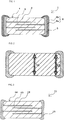
- Fig. 1 is a schematic cross-sectional view of a surface-mountable negative-characteristic thermistor.
- a surface-mountable negative-characteristic thermistor 1 according to the present invention includes internal electrodes 3 disposed in a ceramic body 4 composed of a sintered semiconductor ceramic material showing negative resistance temperature characteristics.
- the ceramic body 4 has a structure in which ceramic layers 2 and the internal electrodes 3 are alternately stacked.
- the internal electrodes 3 extend alternately to end faces of the ceramic body 4.
- External electrodes 5 are formed on the end faces of the ceramic body 4 so as to be electrically connected to the extending internal electrodes 3. Surfaces of the external electrodes 5 are overlaid with plating films 6.
- the semiconductor ceramic materials used for the ceramic body 4 according to the present invention are broadly categorized into semiconductor ceramic materials (1) to (3) described below:
- the incorporation of a predetermined amount of Ti into a semiconductor ceramic material containing Mn and at least one of Ni and Co prevents the erosion of the ceramic body due to a plating solution and improves the strength of the ceramic body.
- Patent Document 1 the use of a semiconductor ceramic material containing Mn and Ni as main constituents and containing Al requires a firing temperature of at least 1,250°C in order to sinter the ceramic body because Al is resistant to sintering.
- the incorporation of Ti in an amount within a predetermined range in place of Al enables a ceramic body to be sintered at a lower firing temperature, such as about 900°C to 1,100°C, and that the resulting ceramic body has excellent thermistor characteristics and reliability comparable with the case where Al is contained.
- hetero-phases e.g., a rock-salt phase
- a spinel phase different from a spinel phase
- the formation of hetero-phases can be inhibited, thereby suppressing a shift in the composition of the spinel phase after firing from an initial composition and preventing a reduction in strength due to the formation of the hetero-phase.
- the semiconductor ceramic material (1) when a thermistor material mainly containing Mn and Ni is fired, spinel phases of Mn and Ni are generally formed.
- a hetero-phase such as a NiO phase which is a rock-salt phase
- the formation of the NiO phase may rapidly increase resistivity and a B constant in response to a change in firing temperature to cause a shift in composition and may significantly shift the composition of the spinel phase in a sintered body from the initial composition.
- Such a NiO phase differs in thermal expansion coefficient from the spinel phase, thus disadvantageously causing the occurrence of cracks during sintering and processing and reducing the strength of the ceramic body.
- low-temperature sintering can be performed.
- the formation of the NiO phase can be inhibited, thereby preventing the reduction in the strength of the ceramic body.
- a hetero-phase such as a rock-salt phase, different from the spinel phase is formed.
- composition ranges of the semiconductor ceramic materials described in the items (1) to (3) are limited will be described below.
- the molar ratio of Mn to Ni is in the range of 55/45 ⁇ a/b ⁇ 90/10.
- the reason for this is as follows: When a/b exceeds 90/10, the ceramic body is insulated; hence, a desired effect for the application as a negative-characteristic thermistor is not obtained.
- a/b is less than 55/45, a large amount of the hetero-phase such as the NiO phase is formed to reduce the strength of the ceramic body, thereby possibly generating cracks during processing the ceramic body.
- the content of Ti is in the range of 0.5 parts by mole to 25 parts by mole.
- a Ti content of less than 0.5 parts by mole cannot sufficiently prevent the erosion of the ceramic body by plating.
- a Ti content exceeding 25 parts by mole results in excessively high resistivity and thus is not preferred.
- the molar ratio of Mn to Ni is in the range of 55/45 ⁇ a/b ⁇ 78.5/21.5 and where the content of Ti is in the range of 5 parts by mole to 25 parts by mole when the total molar quantity of Mn and Ni in the semiconductor ceramic material is defined as 100 parts by mole is preferred because the erosion of the ceramic body due to a plating solution can be further prevented.
- the case where the molar ratio of Mn to Ni is in the range of 55/45 ⁇ a/b ⁇ 70/30 and where the content of Ti is in the range of 5 parts by mole to 25 parts by mole when the total molar quantity of Mn and Ni in the semiconductor ceramic material is defined as 100 parts by mole is preferred because further improved reliability is obtained.
- the molar ratio of Mn to Co is in the range of 10/90 ⁇ a/c ⁇ 70/30.
- the reason for this is as follows: When a/c exceeds 70/30, the ceramic body is insulated; hence, a desired effect for the application as a negative-characteristic thermistor is not obtained. When a/c is less than 10/90, the ceramic body is also insulated; hence, a desired effect for the application as a negative-characteristic thermistor is not obtained.
- the content of Ti is in the range of 1 part by mole to 30 parts by mole.
- a Ti content of less than 1 part by mole cannot sufficiently prevent the erosion of the ceramic body by plating.
- a Ti content exceeding 30 parts by mole results in excessively high resistivity and thus is not preferred.
- a Mn content exceeding 90 mol% results in excessively high resistivity and eliminates usefulness as a thermistor.
- a Mn content of less than 0.1 mol% does not show an addition effect.
- a Ni content exceeding 45 mol% results in the formation of a large amount of the hetero-phase, a reduction in the strength of the body, and significant variations in initial characteristics, thus being not preferred.
- a Ni content of less than 0.1 mol% does not show an addition effect.
- a Co content exceeding 90 mol% results in excessively high resistivity and eliminates usefulness as a thermistor.
- a Co content of less than 0.1 mol% does not show an addition effect.
- the content of Ti is in the range of 0.5 parts by mole to 30 parts by mole.
- a Ti content of less than 0.5 parts by mole cannot sufficiently prevent the erosion of the ceramic body by plating.
- a Ti content exceeding 30 parts by mole results in excessively high resistivity and thus is not preferred.
- the Mn content is in the range of 25 mol% to 65 mol%
- the Ni content is in the range of 5 mol% to 30 mol%
- the Co content is in the range of 5 mol% to 70 mol% (provided that the sum of Mn, Ni, and Co is 100 mol%)
- the Ti content is in the range of 0.5 parts by mole to 30 parts by mole when the total molar quantity of Mn, Ni, and Co in the semiconductor ceramic material is defined as 100 parts by mole is more effective.
- a transition metal element such as Fe or Cu
- the incorporation of Fe reduces variations in initial resistance.
- the incorporation of Cu permits sintering at a lower temperature, thereby improving denseness of the ceramic body.
- the incorporation of Zn is not preferred because plating resistance may degrade due to easy erosion of Zn by a plating solution.
- the semiconductor ceramic layers 2 composed of any one of the semiconductor ceramic materials (1) to (3) according to the present invention may contain impurities from starting materials or included during a production process.
- the impurities include Si, Na, K, Ca, and Zr. It is found that the content of the impurities is about 1,000 ppm or less or at most about 5,000 ppm or less; hence, in the present invention, the impurities do not affect the characteristics.
- Non-limiting examples of materials used for the internal electrodes 3 according to the present invention include elementary substances, such as Ag and Pd; and alloys thereof.
- the internal electrodes each composed of Ag-Pd and having a Ag content of 60 percent by weight to 90 percent by weight can be sufficiently used. That is, the semiconductor ceramic material according to the present invention can be sintered at a low temperature, for example, 900°C to 1,100°C.
- the internal electrodes 3 each composed of a low-melting-point electrode material of Ag-Pd and having a Ag content of 60 percent by weight to 90 percent by weight are used, the internal electrodes 3 can be co-fired with the semiconductor ceramic material; hence, a negative-characteristic thermistor having only small nonuniformity in resistance is obtained.
- the present invention is not limited to such low-temperature sintering. It is to be understood that for example, even when the internal electrodes are composed of pd and fired at a high temperature of 1,100°C or higher, the erosion of the ceramic body by a plating solution can be prevented.
- the external electrodes 5 according to the present invention are each composed of an elementary substance, such as Ag or Pd, or an alloy such as Ag-Pd.
- the use of such external electrodes further improves the connection with the internal electrodes each composed of Ag-Pd and electric continuity.
- the plating films 6 can be appropriately changed in response to an affinity for a metal used for the external electrodes 5.
- the external electrodes 5 are each composed of Ag, a Ni plating film 6a and a Sn plating film 6b are preferably used.
- the ceramic body 4 is easily eroded. Since the surface-mountable negative-characteristic thermistor according to the present invention has excellent plating resistance, even when the acidic plating solution is used, the erosion of the ceramic body 4 by the plating solution can be prevented.
- the erosion of the ceramic body 4 by the plating solution can be prevented without the need for the formation of a protective layer such as a glass layer.
- the glass layer may be formed. That is, also in the case of the surface-mountable negative-characteristic thermistor according to the present invention, for example, in order to be insusceptible to an external environment and to prevent the degradation of characteristics due to temperature, humidity, and the like, a glass layer may be formed on the surface of the ceramic body 4.
- thermoistor 1 having the ceramic body 4 composed of a semiconductor ceramic material containing Mn, Ni, and Ti, will be described below.
- Predetermined amounts of Mn 3 O 4 , NiO, and TiO 2 as starting ceramic materials are weighed, placed into a ball mill containing grinding media such as zirconia balls, and sufficiently wet-ground. The resulting mixture is calcined at a predetermined temperature to form a ceramic powder. An organic binder is added to the ceramic powder. The resulting mixture is wet-mixed to form a slurry. The slurry is formed into ceramic green sheets by a doctor blade process.
- a paste for forming internal electrodes is applied to the ceramic green sheets by screen printing to form electrode patterns.
- the resulting ceramic green sheets having the electrode patterns formed by screen printing are stacked, held by ceramic green sheets not having the electrode patterns, and press-bonded to form a laminate.
- the resulting laminate is cut into pieces having a predetermined size.
- the resulting pieces are placed in a zirconia sagger, calcined, and fired at a predetermined temperature (e.g., 900°C to 1,100°C) to form the piezoelectric ceramic bodies 4 each including the ceramic layers 2 and the internal electrodes 3 that are alternately stacked.
- a paste containing Ag and the like for forming external electrodes is applied to both ends of each ceramic body 4 and baked to form the external electrodes 5.
- the plating films 6a and 6b composed of, for example, Ni and Sn are formed on surfaces of the external electrodes 5 by electrolytic plating. Thereby, a surface-mountable negative-characteristic thermistor according to a first embodiment of the present invention is produced.
- the external electrodes 5 may have satisfactory adhesion and may be formed by a thin-film-forming method, such as sputtering or vacuum evaporation.
- oxides such as Mn 3 O 4 as the starting ceramic materials are used.
- a carbonate or a hydroxide of Mn may be used.
- the same method as the above-described method may be employed.
- the surface-mountable negative-characteristic thermistor according to the present invention is useful for temperature compensation and temperature detection but is not limited thereto. Furthermore, the present invention is not limited to the laminated type as long as the thermistor is surface mountable, i.e., the thermistor has external electrodes disposed on surfaces of the ceramic body chip so as to be surface-mounted on a substrate, the external electrodes having plating films disposed on surfaces of the external electrodes.
- the laminated negative-characteristic thermistor according to the present invention will be described in further detail below.
- Mn 3 O 4 , NiO, and TiO 2 were prepared as starting materials. The materials were mixed in such a manner that the resulting mixtures satisfy compositions of Samples 1 to 54 shown in Table 1.
- the content of Ti shown in Table 1 is the amount of Ti added (part by mole) when the total molar quantity of Mn and Ni is defined as 100 parts by mole.
- Deionized water and a polycarboxylic acid dispersant were added to the starting materials.
- the resulting mixture was mixed and pulverized with media of zirconia balls, dried, calcined at 800°C for 2 hours, and pulverized again with a ball mill to form a calcined powder.
- 40 percent by weight of water and 2.0 percent by weight of polycarboxylic acid dispersant were added to the resulting calcined powder.
- the resulting mixture was mixed for 24 hours, and then 25 percent by weight of an acrylic organic binder and 0.75 percent by weight of polyoxyethylene as a plasticizer were added and mixed for 2 hours to form a ceramic slurry.
- a Ag-Pd conductive paste for forming internal electrodes was prepared by dispersing a metal powder composed of a Ag-Pd alloy (composition: 80 wt% of Ag and 20 wt% of Pd) and an organic binder into an organic solvent.
- the Ag-Pd conductive paste for forming the internal electrodes was applied to a main surface of each ceramic green sheet segment by screen printing.
- the ceramic green sheet segments were stacked in such a manner that the Ag-Pd conductive paste layers to be formed into the internal electrodes were opposed to each other.
- the resulting stack was held by protective ceramic green sheets that were not provided with the Ag-Pd conductive paste for forming the internal electrodes in such a manner that the protective ceramic green sheets were arranged on the top and bottom of the stack.
- the resulting stack was press-bonded and cut into green laminates each having a length of 1.2 mm, a width of 0.6 mm, and a thickness of 0.6 mm.
- the green laminates were calcined in air at 350°C for 10 hours and fired in air at 1,000°C for 2 hours to form the ceramic bodies 4 each including the ceramic layers 2 and the internal electrodes 3 that were alternately stacked.
- a Ag conductive paste for forming external electrodes were prepared by dispersing a Ag powder and an organic binder into an organic solvent.
- the Ag conductive paste for forming the external electrodes was applied to both ends of each ceramic body so as to be electrically connected to the internal electrodes, and baked to form the external electrodes 5.
- Ni plating film 6a and the Sn plating film 6b were sequentially formed by electrolytic plating on surfaces of the external electrodes of the ceramic body 4 having the external electrodes 5 to form the surface-mountable negative-characteristic thermistors 1 of Samples 1 to 54.
- a laminated negative-characteristic thermistor produced by the same method as in Sample 15 was used as REFERENCE EXAMPLE, except that Al 2 O 3 was used in place of TiO 2 , a Ag-Pd alloy (composition: 30 wt% of Ag and 70 wt% of Pd) was used as the internal electrodes, and the firing temperature was 1,300°C.
- composition analysis was performed on the ceramic bodies by inductively coupled plasma-atomic emission spectroscopy (ICP-AES). The results demonstrated that the compositions of the resulting ceramic bodies were equal to initial compositions thereof.
- the percentage of pore areas was measured as an index of sinterability.
- the percentage of the pore areas was measured as follows: After the resulting ceramic body of each sample was immersed in a resin, mirror polishing was performed in the direction parallel to an end face of the ceramic body. Observation was made with a scanning electron microscope (SEM). The sum of the pore areas was determined by image analysis, and the percentage of the pore areas was calculated.
- B constant K InR 25 ⁇ ⁇ InR 50 ⁇ / 1 / 298.15 ⁇ 1 / 323.15
- B constant 3 CV % standard deviation ⁇ 300 / mean of B constant
- single-plate ceramic bodies not including the internal electrodes and negative-characteristic thermistors including Ag external electrodes disposed on both main surfaces of each of the ceramic bodies are prepared as samples produced by the same production conditions as in Samples 1 to 54. Resistance of these samples was measured. The measured resistance values were defined as resistivity of the ceramic materials.
- the percentage of the pore areas is as small as 5% or less.
- the results demonstrate that even at a low firing temperature of 1,000°C, each sample is sufficiently sintered and has sufficient B constant and resistivity.
- the results demonstrate that the percentage of erosion by plating is 1% or less, which is more excellent.
- Negative-characteristic thermistors of Samples 55 to 74 were produced by the same method as in EXAMPLE 1, except that the compositions of the mixtures of the starting materials were adjusted as described above.
- the composition analysis of the ceramic bodies was performed on the resulting laminated negative-characteristic thermistors of Samples 55 to 74 by inductively coupled plasma-atomic emission spectroscopy (ICP-AES). The results demonstrated that the compositions of the resulting ceramic bodies were equal to initial compositions thereof.
- Mn 3 O 4 , NiO, Fe 2 O 3 , CuO, and TiO 2 were prepared as starting materials.
- Samples 75 to 113 were produced by the same method as in EXAMPLE 1, except that the starting materials were mixed in such a manner that the resulting mixtures satisfy compositions shown in Table 3.
- the content of Ti shown in Table 3 is the amount of Ti added (part by mole) when the total molar quantity of Mn and Ni is defined as 100 parts by mole.
- the same characteristic evaluation was performed by the same method as in EXAMPLE 1. Table 3 shows the results.
- the content of Cu is in the range of 3 parts by mole to 7 parts by mole when the total molar quantity of Mn and Ni is defined as 100 parts by mole; hence, the dense ceramic body having a low percentage of the pore areas is obtained even when the ceramic body is formed by low-temperature sintering.
- the content of Fe is represented as the proportion of Fe when the sum of Mn, Ni, and Fe is defined as 100 mol%.
- the proportion is converted into the amount of Fe added (part by mole) when the total amount of Mn and Ni is defined as 100 parts by mole.
- thermoelectric thermistors each including a ceramic body composed of a semiconductor ceramic material containing Mn, Co, and Ti
- comparisons among the thermistors having different proportions of Mn, Co, and Ti in the semiconductor ceramic materials were made.
- Samples 114 to 140 were produced by the same method as in EXAMPLE 1, except that the materials were mixed in such a manner that the resulting mixtures satisfy compositions of Samples 114 to 140 shown in Table 4.
- the content of Ti shown in Table 1 is the amount of Ti added (part by mole) when the total molar quantity of Mn and Co is defined as 100 parts by mole.
- the characteristic evaluation was performed on the resulting laminated negative-characteristic thermistors of Samples 114 to 140 by the same method as in EXAMPLE 1. Table 4 shows the results.
- the percentage of the pore areas is as low as 3.0% or less.
- the results demonstrate that even at a low firing temperature, each sample is sufficiently sintered and has sufficient B constant and resistivity.
- the percentage of erosion by plating is 4.0% or less, and ⁇ R 25 /R 25 , which indicates reliability, is 0.5% or less; hence, the more excellent laminated negative-characteristic thermistor is obtained.
- the content of Fe is in the range of 7 parts by mole to 31 parts by mole when the total molar quantity of Mn and Co is defined as 100 parts by mole, thus reducing variations in characteristic value (B constant 3CV).
- the content of Cu is in the range of 2 parts by mole to 7 parts by mole when the total molar quantity of Mn and Co is defined as 100 parts by mole; hence, the dense ceramic body having a low percentage of the pore areas is obtained even when the ceramic body is formed by low-temperature sintering.
- the sum of Mn, Co, and Fe is defined as 100 mol%
- the sum of Mn, Co, and Cu is defined as 100 mol%
- the sum of Mn, Co, Fe, and Cu is defined as 100 mol%.
- contents of Fe and Cu are represented in terms of part by mole when the sum of Mn and Co is defined as 100 parts by mole.
- semiconductor ceramic materials according to the sixth invention the materials each containing Mn, Ni, and Co as main constituents and containing Ti, comparisons among the materials having different compositions are made. Furthermore, comparisons among the semiconductor ceramic materials containing another transition metal element are made.
- Mn 3 O 9 , NiO, Co 3 O 4 , Fe 2 O 3 , CuO, and TiO 2 were prepared as starting materials.
- Samples 198 to 272 were produced by the same method as in EXAMPLE 1, except that the starting materials were mixed in such a manner that the resulting mixtures satisfy compositions shown in Tables 7 and 8.
- the content of Ti shown in each of Tables 7 and 8 is the amount of Ti added (part by mole) when the total amount of Mn, Ni, and Co in the semiconductor ceramic material is defined as 100 parts by mole.
- the same characteristic evaluation was performed by the same method as in EXAMPLE 1. Tables 7 and 8 show the results.
- the content of Cu is in the range of 1 part by mole to 5 parts by mole when the total molar quantity of Mn, Ni, and Co is defined as 100 parts by mole; hence, the dense ceramic body having a low percentage of the pore areas is obtained even when the ceramic body is formed by low-temperature sintering.
- the sum of Mn, Ni, Co, and Fe is defined as 100 mol% or the sum of Mn, Ni, Co, and Cu is defined as 100 mol%.
- contents of Fe and Cu are represented in terms of part by mole when the sum of Mn, Ni, and Co is defined as 100 parts by mole.
- Samples 273 to 277 were produced by the same method as in Sample 5, except that in a Ag-Pd internal electrode, Ag was incorporated in an amount described in Table 7.
- Samples 278 to 282 were produced by the same method as in Sample 117, except that Ag was incorporated in an amount described in Table 9.
- the same characteristic evaluation was performed by the same method as in EXAMPLE 1. Table 9 shows the results.
- the semiconductor ceramic material according to the present invention can be co-fired with such a Ag-Pd internal electrode material, thereby producing an excellent negative-characteristic thermistor.
- the results demonstrate that the erosion of the ceramic body by a plating solution can be suppressed, and the high-reliability negative-characteristic thermistors having high flexural strength can be obtained.
Applications Claiming Priority (2)
| Application Number | Priority Date | Filing Date | Title |
|---|---|---|---|
| JP2005032339 | 2005-02-08 | ||
| EP06713134.2A EP1848010B1 (en) | 2005-02-08 | 2006-02-06 | Surface mounting-type negative characteristic thermistor |
Related Parent Applications (2)
| Application Number | Title | Priority Date | Filing Date |
|---|---|---|---|
| EP06713134.2 Division | 2006-02-06 | ||
| EP06713134.2A Division EP1848010B1 (en) | 2005-02-08 | 2006-02-06 | Surface mounting-type negative characteristic thermistor |
Publications (3)
| Publication Number | Publication Date |
|---|---|
| EP2546840A2 EP2546840A2 (en) | 2013-01-16 |
| EP2546840A3 EP2546840A3 (en) | 2013-01-23 |
| EP2546840B1 true EP2546840B1 (en) | 2017-04-19 |
Family
ID=36793079
Family Applications (3)
| Application Number | Title | Priority Date | Filing Date |
|---|---|---|---|
| EP12187812.8A Active EP2549491B1 (en) | 2005-02-08 | 2006-02-06 | Surface mountable negative coefficient characteristic ceramic thermistor based on Mn, Co and Ti |
| EP06713134.2A Active EP1848010B1 (en) | 2005-02-08 | 2006-02-06 | Surface mounting-type negative characteristic thermistor |
| EP12187814.4A Active EP2546840B1 (en) | 2005-02-08 | 2006-02-06 | Surface-mountable negative-characteristic ceramic thermistor based on Mn, Co, Ni and Ti compounds |
Family Applications Before (2)
| Application Number | Title | Priority Date | Filing Date |
|---|---|---|---|
| EP12187812.8A Active EP2549491B1 (en) | 2005-02-08 | 2006-02-06 | Surface mountable negative coefficient characteristic ceramic thermistor based on Mn, Co and Ti |
| EP06713134.2A Active EP1848010B1 (en) | 2005-02-08 | 2006-02-06 | Surface mounting-type negative characteristic thermistor |
Country Status (7)
| Country | Link |
|---|---|
| US (2) | US7548149B2 (zh) |
| EP (3) | EP2549491B1 (zh) |
| JP (2) | JP4726890B2 (zh) |
| KR (1) | KR100894967B1 (zh) |
| CN (3) | CN101116154A (zh) |
| TW (1) | TW200701262A (zh) |
| WO (1) | WO2006085507A1 (zh) |
Families Citing this family (21)
| Publication number | Priority date | Publication date | Assignee | Title |
|---|---|---|---|---|
| EP2259273A4 (en) * | 2008-03-28 | 2015-08-26 | Murata Manufacturing Co | NTC RESISTANCE PORCELAIN, METHOD FOR PRODUCING THE NTC RESISTANCE PORCELAIN AND NTC RESISTANCE |
| US8115587B2 (en) | 2008-03-28 | 2012-02-14 | Murata Manufacturing Co., Ltd. | NTC thermistor ceramic, method for producing NTC thermistor ceramic, and NTC thermistor |
| JP5141775B2 (ja) * | 2008-12-02 | 2013-02-13 | 株式会社村田製作所 | ガスセンサ |
| CN102686532B (zh) * | 2010-01-12 | 2014-05-28 | 株式会社村田制作所 | Ntc热敏电阻用半导体瓷器组合物及ntc热敏电阻 |
| JP5533387B2 (ja) * | 2010-07-21 | 2014-06-25 | 株式会社村田製作所 | セラミック電子部品 |
| JP5699819B2 (ja) * | 2010-07-21 | 2015-04-15 | 株式会社村田製作所 | セラミック電子部品 |
| DE102010044856A1 (de) * | 2010-09-09 | 2012-03-15 | Epcos Ag | Widerstandsbauelement und Verfahren zur Herstellung eines Widerstandsbauelements |
| WO2012105955A1 (en) * | 2011-02-01 | 2012-08-09 | Hewlett-Packard Development Company L.P. | Negative differential resistance device |
| JP5510479B2 (ja) | 2012-03-03 | 2014-06-04 | 株式会社村田製作所 | Ntcサーミスタ用半導体磁器組成物 |
| CN104335295B (zh) * | 2012-05-28 | 2017-03-29 | 株式会社村田制作所 | Ntc热敏电阻元件及其制造方法 |
| WO2015008500A1 (ja) * | 2013-07-17 | 2015-01-22 | 株式会社村田製作所 | 内部電極ペースト |
| US9558869B2 (en) | 2013-07-30 | 2017-01-31 | Hewlett Packard Enterprise Development Lp | Negative differential resistance device |
| JP2015133359A (ja) * | 2014-01-09 | 2015-07-23 | 株式会社村田製作所 | 負特性サーミスタおよびその製造方法 |
| CN104844163A (zh) * | 2015-04-10 | 2015-08-19 | 南京工业大学 | 一种高阻值高b值ntc热敏陶瓷材料及制备方法 |
| DE102015110607A1 (de) * | 2015-07-01 | 2017-01-05 | Epcos Ag | Verfahren zur Herstellung eines elektrischen Bauelements |
| WO2017022373A1 (ja) | 2015-07-31 | 2017-02-09 | 株式会社村田製作所 | 温度センサ |
| CN111295724A (zh) * | 2017-11-02 | 2020-06-16 | 株式会社村田制作所 | 热敏电阻元件及其制造方法 |
| DE102018115513A1 (de) * | 2018-06-27 | 2020-01-02 | Tdk Electronics Ag | NTC-Masse, Thermistor und Verfahren zur Herstellung des Thermistors |
| DE102018116222A1 (de) | 2018-07-04 | 2020-01-09 | Tdk Electronics Ag | Keramikmaterial, Varistor und Verfahren zur Herstellung des Keramikmaterials und des Varistors |
| US11756712B2 (en) | 2019-09-20 | 2023-09-12 | Tdk Electronics Ag | Sensor device and method for manufacturing a sensor device |
| EP3901115A1 (en) | 2020-04-24 | 2021-10-27 | Nederlandse Organisatie voor toegepast- natuurwetenschappelijk Onderzoek TNO | A printable ntc ink composition and method of manufacturing thereof |
Family Cites Families (31)
| Publication number | Priority date | Publication date | Assignee | Title |
|---|---|---|---|---|
| GB638436A (en) | 1939-05-17 | 1950-06-07 | Western Electric Co | Resistance units and methods of making them |
| NL301822A (zh) * | 1963-12-13 | |||
| US4231902A (en) * | 1978-08-23 | 1980-11-04 | General Motors Corporation | Thermistor with more stable beta |
| FR2582851B1 (fr) * | 1985-06-04 | 1988-07-08 | Univ Toulouse | Compositions de manganites de metaux de transition sous forme de particules ou sous forme de ceramiques, leur preparation et leur application notamment dans la fabrication de thermistances |
| JPS62137805A (ja) | 1985-12-12 | 1987-06-20 | 株式会社村田製作所 | 負特性積層チップ型サーミスタ |
| JPS63315556A (ja) * | 1987-06-18 | 1988-12-23 | Matsushita Electric Ind Co Ltd | サーミスタ磁器組成物 |
| JPS63315555A (ja) * | 1987-06-18 | 1988-12-23 | Matsushita Electric Ind Co Ltd | サーミスタ磁器組成物 |
| JPS63315550A (ja) * | 1987-06-18 | 1988-12-23 | Matsushita Electric Ind Co Ltd | サ−ミスタ磁器組成物 |
| JPH01215752A (ja) | 1988-02-24 | 1989-08-29 | Nippon Denso Co Ltd | ZnO系負特性半導体材料およびこの材料を用いた発熱体、ならびにこの発熱体を用いた過電流保護装置 |
| JPH02276203A (ja) * | 1989-04-18 | 1990-11-13 | Matsushita Electric Ind Co Ltd | 積層型サーミスタの製造方法 |
| GB2242065C (en) * | 1990-03-16 | 1996-02-08 | Ecco Ltd | Varistor ink formulations |
| KR930005249B1 (ko) * | 1990-08-16 | 1993-06-17 | 한국과학기술연구원 | 금속산화물계 써미스터 재료 |
| US5246628A (en) | 1990-08-16 | 1993-09-21 | Korea Institute Of Science & Technology | Metal oxide group thermistor material |
| JPH053103A (ja) | 1991-06-26 | 1993-01-08 | Matsushita Electric Ind Co Ltd | サーミスタ磁器 |
| JPH06231906A (ja) | 1993-01-28 | 1994-08-19 | Mitsubishi Materials Corp | サーミスタ |
| JP2676469B2 (ja) * | 1993-04-23 | 1997-11-17 | 株式会社芝浦電子 | Ntcサーミスタの製造方法 |
| CN1030873C (zh) * | 1993-12-04 | 1996-01-31 | 清华大学 | 一种制备多层叠片热敏电阻器的方法 |
| DE4480337T1 (de) * | 1993-12-27 | 1996-12-19 | Komatsu Mfg Co Ltd | Thermistor-Sinterkörper und diesen verwendende Thermistorvorrichtung |
| JPH07235405A (ja) * | 1993-12-27 | 1995-09-05 | Komatsu Ltd | サーミスタ焼結体 |
| FR2719587B1 (fr) * | 1994-05-03 | 1996-07-12 | Roussel Uclaf | Nouveaux dérivés de l'érythromycine, leur procédé de préparation et leur application comme médicaments. |
| TW421413U (en) * | 1994-07-18 | 2001-02-01 | Murata Manufacturing Co | Electronic apparatus and surface mounting devices therefor |
| JP3317246B2 (ja) | 1998-09-04 | 2002-08-26 | 三菱マテリアル株式会社 | 複合セラミック及び複合セラミック素子 |
| JP2000277229A (ja) | 1999-03-23 | 2000-10-06 | Tokin Corp | 表面実装型サージ吸収素子の製造方法 |
| WO2001082314A1 (de) * | 2000-04-25 | 2001-11-01 | Epcos Ag | Elektrisches bauelement, verfahren zu dessen herstellung und dessen verwendung |
| JP3653447B2 (ja) * | 2000-05-22 | 2005-05-25 | 日本化学工業株式会社 | 被覆金属粉末及びその製造方法、被覆金属粉末ペースト並びにセラミックス積層部品 |
| JP3711857B2 (ja) | 2000-10-11 | 2005-11-02 | 株式会社村田製作所 | 負の抵抗温度特性を有する半導体磁器組成物及び負特性サーミスタ |
| JP3757794B2 (ja) | 2000-12-26 | 2006-03-22 | 株式会社村田製作所 | サーミスタ用半導体磁器及びそれを用いたチップ型サーミスタ |
| DE10159451A1 (de) * | 2001-12-04 | 2003-06-26 | Epcos Ag | Elektrisches Bauelement mit einem negativen Temperaturkoeffizienten |
| JP2003217905A (ja) | 2002-01-25 | 2003-07-31 | Murata Mfg Co Ltd | チップ型サーミスタおよびその製造方法 |
| JP4029170B2 (ja) | 2002-07-16 | 2008-01-09 | 株式会社村田製作所 | 負特性サーミスタの製造方法 |
| JP4337436B2 (ja) | 2003-07-14 | 2009-09-30 | 株式会社村田製作所 | サーミスタ素子の製造方法 |
-
2006
- 2006-02-06 EP EP12187812.8A patent/EP2549491B1/en active Active
- 2006-02-06 KR KR1020077018187A patent/KR100894967B1/ko active IP Right Grant
- 2006-02-06 EP EP06713134.2A patent/EP1848010B1/en active Active
- 2006-02-06 CN CNA2006800040977A patent/CN101116154A/zh active Pending
- 2006-02-06 CN CN2011101368093A patent/CN102290174A/zh active Pending
- 2006-02-06 CN CN201110136821.4A patent/CN102290175B/zh active Active
- 2006-02-06 EP EP12187814.4A patent/EP2546840B1/en active Active
- 2006-02-06 JP JP2007502596A patent/JP4726890B2/ja active Active
- 2006-02-06 WO PCT/JP2006/301991 patent/WO2006085507A1/ja active Application Filing
- 2006-02-08 TW TW095104259A patent/TW200701262A/zh unknown
-
2007
- 2007-08-07 US US11/835,272 patent/US7548149B2/en active Active
-
2008
- 2008-04-07 JP JP2008099134A patent/JP5064286B2/ja active Active
-
2009
- 2009-03-03 US US12/396,600 patent/US7948354B2/en active Active
Non-Patent Citations (1)
| Title |
|---|
| None * |
Also Published As
| Publication number | Publication date |
|---|---|
| CN102290174A (zh) | 2011-12-21 |
| KR100894967B1 (ko) | 2009-04-24 |
| US7548149B2 (en) | 2009-06-16 |
| US20080048821A1 (en) | 2008-02-28 |
| WO2006085507A1 (ja) | 2006-08-17 |
| EP2549491A1 (en) | 2013-01-23 |
| EP1848010B1 (en) | 2013-05-15 |
| TW200701262A (en) | 2007-01-01 |
| EP1848010A1 (en) | 2007-10-24 |
| CN102290175A (zh) | 2011-12-21 |
| US20090167482A1 (en) | 2009-07-02 |
| CN101116154A (zh) | 2008-01-30 |
| EP2546840A3 (en) | 2013-01-23 |
| CN102290175B (zh) | 2014-06-11 |
| KR20070095397A (ko) | 2007-09-28 |
| EP2549491B1 (en) | 2017-07-26 |
| JPWO2006085507A1 (ja) | 2008-06-26 |
| US7948354B2 (en) | 2011-05-24 |
| TWI308348B (zh) | 2009-04-01 |
| EP1848010A4 (en) | 2011-11-30 |
| JP2008177611A (ja) | 2008-07-31 |
| JP4726890B2 (ja) | 2011-07-20 |
| EP2546840A2 (en) | 2013-01-16 |
| JP5064286B2 (ja) | 2012-10-31 |
Similar Documents
| Publication | Publication Date | Title |
|---|---|---|
| EP2546840B1 (en) | Surface-mountable negative-characteristic ceramic thermistor based on Mn, Co, Ni and Ti compounds | |
| JP4491794B2 (ja) | 誘電体セラミック、及び積層セラミックコンデンサ | |
| US6301092B1 (en) | Ceramic capacitor and method for making the same | |
| US6939822B2 (en) | Dielectric ceramic, methods for making and evaluating the same, and monolithic ceramic electronic component | |
| JP4345071B2 (ja) | 積層セラミックコンデンサ、及び該積層セラミックコンデンサの製造方法 | |
| US8228161B2 (en) | Semiconductor ceramic and positive temperature coefficient thermistor | |
| US8445396B2 (en) | Dielectric ceramic and laminated ceramic capacitor | |
| US7381672B2 (en) | Dielectric ceramic material and multilayer ceramic capacitor | |
| EP2377836A1 (en) | Semiconductor ceramic and positive temperature coefficient thermistor | |
| US20050282403A1 (en) | Ceramic electronic device and the production method | |
| US9530547B2 (en) | Laminated PTC thermistor element | |
| EP2189430A1 (en) | Semiconductor ceramic material and ntc thermistor | |
| EP3196904A1 (en) | Chip-type ceramic semiconductor electronic component | |
| US7679485B2 (en) | Multilayer positive temperature coefficient thermistor | |
| JP7327065B2 (ja) | 誘電体組成物および電子部品 | |
| US20230303451A1 (en) | Dielectric composition and multilayer ceramic electronic device | |
| US20220380257A1 (en) | Dielectric composition and multilayer ceramic electronic device | |
| JP7310543B2 (ja) | 誘電体組成物および電子部品 | |
| EP2450327A1 (en) | Semiconductor ceramic and positive-coefficient thermistor | |
| CN113628879A (zh) | 电介质、电子器件和层叠陶瓷电容器 | |
| JP2004210604A (ja) | 誘電体セラミック、及び積層セラミックコンデンサ | |
| JP2008060612A (ja) | 表面実装型負特性サーミスタ | |
| JP2006160531A (ja) | 誘電体磁器組成物及び磁器コンデンサとそれらの製造方法 | |
| CN115403368A (zh) | 电介质组合物及层叠陶瓷电子部件 |
Legal Events
| Date | Code | Title | Description |
|---|---|---|---|
| PUAL | Search report despatched |
Free format text: ORIGINAL CODE: 0009013 |
|
| PUAI | Public reference made under article 153(3) epc to a published international application that has entered the european phase |
Free format text: ORIGINAL CODE: 0009012 |
|
| AC | Divisional application: reference to earlier application |
Ref document number: 1848010 Country of ref document: EP Kind code of ref document: P |
|
| AK | Designated contracting states |
Kind code of ref document: A2 Designated state(s): AT BE BG CH CY CZ DE DK EE ES FI FR GB GR HU IE IS IT LI LT LU LV MC NL PL PT RO SE SI SK TR |
|
| AK | Designated contracting states |
Kind code of ref document: A3 Designated state(s): AT BE BG CH CY CZ DE DK EE ES FI FR GB GR HU IE IS IT LI LT LU LV MC NL PL PT RO SE SI SK TR |
|
| RIC1 | Information provided on ipc code assigned before grant |
Ipc: C04B 35/01 20060101ALI20121220BHEP Ipc: H01C 7/04 20060101AFI20121220BHEP Ipc: C04B 35/00 20060101ALI20121220BHEP |
|
| 17P | Request for examination filed |
Effective date: 20130723 |
|
| RBV | Designated contracting states (corrected) |
Designated state(s): AT BE BG CH CY CZ DE DK EE ES FI FR GB GR HU IE IS IT LI LT LU LV MC NL PL PT RO SE SI SK TR |
|
| REG | Reference to a national code |
Ref country code: DE Ref legal event code: R079 Ref document number: 602006052350 Country of ref document: DE Free format text: PREVIOUS MAIN CLASS: H01C0007040000 Ipc: H01C0001148000 |
|
| GRAP | Despatch of communication of intention to grant a patent |
Free format text: ORIGINAL CODE: EPIDOSNIGR1 |
|
| RIC1 | Information provided on ipc code assigned before grant |
Ipc: H01C 1/148 20060101AFI20161013BHEP Ipc: C04B 35/01 20060101ALI20161013BHEP Ipc: H01C 7/04 20060101ALI20161013BHEP Ipc: H01C 7/18 20060101ALI20161013BHEP Ipc: C04B 35/626 20060101ALI20161013BHEP |
|
| INTG | Intention to grant announced |
Effective date: 20161104 |
|
| GRAS | Grant fee paid |
Free format text: ORIGINAL CODE: EPIDOSNIGR3 |
|
| GRAA | (expected) grant |
Free format text: ORIGINAL CODE: 0009210 |
|
| AC | Divisional application: reference to earlier application |
Ref document number: 1848010 Country of ref document: EP Kind code of ref document: P |
|
| AK | Designated contracting states |
Kind code of ref document: B1 Designated state(s): AT BE BG CH CY CZ DE DK EE ES FI FR GB GR HU IE IS IT LI LT LU LV MC NL PL PT RO SE SI SK TR |
|
| REG | Reference to a national code |
Ref country code: GB Ref legal event code: FG4D |
|
| REG | Reference to a national code |
Ref country code: CH Ref legal event code: EP |
|
| REG | Reference to a national code |
Ref country code: AT Ref legal event code: REF Ref document number: 886656 Country of ref document: AT Kind code of ref document: T Effective date: 20170515 |
|
| REG | Reference to a national code |
Ref country code: IE Ref legal event code: FG4D |
|
| REG | Reference to a national code |
Ref country code: DE Ref legal event code: R096 Ref document number: 602006052350 Country of ref document: DE |
|
| REG | Reference to a national code |
Ref country code: NL Ref legal event code: MP Effective date: 20170419 |
|
| REG | Reference to a national code |
Ref country code: LT Ref legal event code: MG4D |
|
| REG | Reference to a national code |
Ref country code: AT Ref legal event code: MK05 Ref document number: 886656 Country of ref document: AT Kind code of ref document: T Effective date: 20170419 |
|
| PG25 | Lapsed in a contracting state [announced via postgrant information from national office to epo] |
Ref country code: NL Free format text: LAPSE BECAUSE OF FAILURE TO SUBMIT A TRANSLATION OF THE DESCRIPTION OR TO PAY THE FEE WITHIN THE PRESCRIBED TIME-LIMIT Effective date: 20170419 |
|
| PG25 | Lapsed in a contracting state [announced via postgrant information from national office to epo] |
Ref country code: AT Free format text: LAPSE BECAUSE OF FAILURE TO SUBMIT A TRANSLATION OF THE DESCRIPTION OR TO PAY THE FEE WITHIN THE PRESCRIBED TIME-LIMIT Effective date: 20170419 Ref country code: LT Free format text: LAPSE BECAUSE OF FAILURE TO SUBMIT A TRANSLATION OF THE DESCRIPTION OR TO PAY THE FEE WITHIN THE PRESCRIBED TIME-LIMIT Effective date: 20170419 Ref country code: GR Free format text: LAPSE BECAUSE OF FAILURE TO SUBMIT A TRANSLATION OF THE DESCRIPTION OR TO PAY THE FEE WITHIN THE PRESCRIBED TIME-LIMIT Effective date: 20170720 Ref country code: FI Free format text: LAPSE BECAUSE OF FAILURE TO SUBMIT A TRANSLATION OF THE DESCRIPTION OR TO PAY THE FEE WITHIN THE PRESCRIBED TIME-LIMIT Effective date: 20170419 Ref country code: ES Free format text: LAPSE BECAUSE OF FAILURE TO SUBMIT A TRANSLATION OF THE DESCRIPTION OR TO PAY THE FEE WITHIN THE PRESCRIBED TIME-LIMIT Effective date: 20170419 |
|
| PG25 | Lapsed in a contracting state [announced via postgrant information from national office to epo] |
Ref country code: SE Free format text: LAPSE BECAUSE OF FAILURE TO SUBMIT A TRANSLATION OF THE DESCRIPTION OR TO PAY THE FEE WITHIN THE PRESCRIBED TIME-LIMIT Effective date: 20170419 Ref country code: PL Free format text: LAPSE BECAUSE OF FAILURE TO SUBMIT A TRANSLATION OF THE DESCRIPTION OR TO PAY THE FEE WITHIN THE PRESCRIBED TIME-LIMIT Effective date: 20170419 Ref country code: IS Free format text: LAPSE BECAUSE OF FAILURE TO SUBMIT A TRANSLATION OF THE DESCRIPTION OR TO PAY THE FEE WITHIN THE PRESCRIBED TIME-LIMIT Effective date: 20170819 Ref country code: LV Free format text: LAPSE BECAUSE OF FAILURE TO SUBMIT A TRANSLATION OF THE DESCRIPTION OR TO PAY THE FEE WITHIN THE PRESCRIBED TIME-LIMIT Effective date: 20170419 Ref country code: BG Free format text: LAPSE BECAUSE OF FAILURE TO SUBMIT A TRANSLATION OF THE DESCRIPTION OR TO PAY THE FEE WITHIN THE PRESCRIBED TIME-LIMIT Effective date: 20170719 |
|
| REG | Reference to a national code |
Ref country code: DE Ref legal event code: R097 Ref document number: 602006052350 Country of ref document: DE |
|
| PG25 | Lapsed in a contracting state [announced via postgrant information from national office to epo] |
Ref country code: CZ Free format text: LAPSE BECAUSE OF FAILURE TO SUBMIT A TRANSLATION OF THE DESCRIPTION OR TO PAY THE FEE WITHIN THE PRESCRIBED TIME-LIMIT Effective date: 20170419 Ref country code: RO Free format text: LAPSE BECAUSE OF FAILURE TO SUBMIT A TRANSLATION OF THE DESCRIPTION OR TO PAY THE FEE WITHIN THE PRESCRIBED TIME-LIMIT Effective date: 20170419 Ref country code: EE Free format text: LAPSE BECAUSE OF FAILURE TO SUBMIT A TRANSLATION OF THE DESCRIPTION OR TO PAY THE FEE WITHIN THE PRESCRIBED TIME-LIMIT Effective date: 20170419 Ref country code: SK Free format text: LAPSE BECAUSE OF FAILURE TO SUBMIT A TRANSLATION OF THE DESCRIPTION OR TO PAY THE FEE WITHIN THE PRESCRIBED TIME-LIMIT Effective date: 20170419 Ref country code: DK Free format text: LAPSE BECAUSE OF FAILURE TO SUBMIT A TRANSLATION OF THE DESCRIPTION OR TO PAY THE FEE WITHIN THE PRESCRIBED TIME-LIMIT Effective date: 20170419 |
|
| PLBE | No opposition filed within time limit |
Free format text: ORIGINAL CODE: 0009261 |
|
| STAA | Information on the status of an ep patent application or granted ep patent |
Free format text: STATUS: NO OPPOSITION FILED WITHIN TIME LIMIT |
|
| PG25 | Lapsed in a contracting state [announced via postgrant information from national office to epo] |
Ref country code: IT Free format text: LAPSE BECAUSE OF FAILURE TO SUBMIT A TRANSLATION OF THE DESCRIPTION OR TO PAY THE FEE WITHIN THE PRESCRIBED TIME-LIMIT Effective date: 20170419 |
|
| 26N | No opposition filed |
Effective date: 20180122 |
|
| PG25 | Lapsed in a contracting state [announced via postgrant information from national office to epo] |
Ref country code: SI Free format text: LAPSE BECAUSE OF FAILURE TO SUBMIT A TRANSLATION OF THE DESCRIPTION OR TO PAY THE FEE WITHIN THE PRESCRIBED TIME-LIMIT Effective date: 20170419 |
|
| REG | Reference to a national code |
Ref country code: CH Ref legal event code: PL |
|
| PG25 | Lapsed in a contracting state [announced via postgrant information from national office to epo] |
Ref country code: MC Free format text: LAPSE BECAUSE OF FAILURE TO SUBMIT A TRANSLATION OF THE DESCRIPTION OR TO PAY THE FEE WITHIN THE PRESCRIBED TIME-LIMIT Effective date: 20170419 |
|
| GBPC | Gb: european patent ceased through non-payment of renewal fee |
Effective date: 20180206 |
|
| REG | Reference to a national code |
Ref country code: IE Ref legal event code: MM4A |
|
| REG | Reference to a national code |
Ref country code: BE Ref legal event code: MM Effective date: 20180228 |
|
| PG25 | Lapsed in a contracting state [announced via postgrant information from national office to epo] |
Ref country code: LI Free format text: LAPSE BECAUSE OF NON-PAYMENT OF DUE FEES Effective date: 20180228 Ref country code: CH Free format text: LAPSE BECAUSE OF NON-PAYMENT OF DUE FEES Effective date: 20180228 Ref country code: LU Free format text: LAPSE BECAUSE OF NON-PAYMENT OF DUE FEES Effective date: 20180206 |
|
| REG | Reference to a national code |
Ref country code: FR Ref legal event code: ST Effective date: 20181031 |
|
| PG25 | Lapsed in a contracting state [announced via postgrant information from national office to epo] |
Ref country code: IE Free format text: LAPSE BECAUSE OF NON-PAYMENT OF DUE FEES Effective date: 20180206 |
|
| PG25 | Lapsed in a contracting state [announced via postgrant information from national office to epo] |
Ref country code: BE Free format text: LAPSE BECAUSE OF NON-PAYMENT OF DUE FEES Effective date: 20180228 Ref country code: FR Free format text: LAPSE BECAUSE OF NON-PAYMENT OF DUE FEES Effective date: 20180228 Ref country code: GB Free format text: LAPSE BECAUSE OF NON-PAYMENT OF DUE FEES Effective date: 20180206 |
|
| PG25 | Lapsed in a contracting state [announced via postgrant information from national office to epo] |
Ref country code: TR Free format text: LAPSE BECAUSE OF FAILURE TO SUBMIT A TRANSLATION OF THE DESCRIPTION OR TO PAY THE FEE WITHIN THE PRESCRIBED TIME-LIMIT Effective date: 20170419 |
|
| PG25 | Lapsed in a contracting state [announced via postgrant information from national office to epo] |
Ref country code: HU Free format text: LAPSE BECAUSE OF FAILURE TO SUBMIT A TRANSLATION OF THE DESCRIPTION OR TO PAY THE FEE WITHIN THE PRESCRIBED TIME-LIMIT; INVALID AB INITIO Effective date: 20060206 Ref country code: PT Free format text: LAPSE BECAUSE OF FAILURE TO SUBMIT A TRANSLATION OF THE DESCRIPTION OR TO PAY THE FEE WITHIN THE PRESCRIBED TIME-LIMIT Effective date: 20170419 |
|
| PG25 | Lapsed in a contracting state [announced via postgrant information from national office to epo] |
Ref country code: CY Free format text: LAPSE BECAUSE OF FAILURE TO SUBMIT A TRANSLATION OF THE DESCRIPTION OR TO PAY THE FEE WITHIN THE PRESCRIBED TIME-LIMIT Effective date: 20170419 |
|
| PGFP | Annual fee paid to national office [announced via postgrant information from national office to epo] |
Ref country code: DE Payment date: 20230216 Year of fee payment: 18 |