EP2450754A2 - Bilderzeugungsvorrichtung - Google Patents
Bilderzeugungsvorrichtung Download PDFInfo
- Publication number
- EP2450754A2 EP2450754A2 EP11187592A EP11187592A EP2450754A2 EP 2450754 A2 EP2450754 A2 EP 2450754A2 EP 11187592 A EP11187592 A EP 11187592A EP 11187592 A EP11187592 A EP 11187592A EP 2450754 A2 EP2450754 A2 EP 2450754A2
- Authority
- EP
- European Patent Office
- Prior art keywords
- fixing
- target temperature
- recording medium
- temperature
- image
- Prior art date
- Legal status (The legal status is an assumption and is not a legal conclusion. Google has not performed a legal analysis and makes no representation as to the accuracy of the status listed.)
- Granted
Links
Images







Classifications
-
- G—PHYSICS
- G03—PHOTOGRAPHY; CINEMATOGRAPHY; ANALOGOUS TECHNIQUES USING WAVES OTHER THAN OPTICAL WAVES; ELECTROGRAPHY; HOLOGRAPHY
- G03G—ELECTROGRAPHY; ELECTROPHOTOGRAPHY; MAGNETOGRAPHY
- G03G15/00—Apparatus for electrographic processes using a charge pattern
- G03G15/20—Apparatus for electrographic processes using a charge pattern for fixing, e.g. by using heat
- G03G15/2003—Apparatus for electrographic processes using a charge pattern for fixing, e.g. by using heat using heat
- G03G15/2014—Apparatus for electrographic processes using a charge pattern for fixing, e.g. by using heat using heat using contact heat
- G03G15/2039—Apparatus for electrographic processes using a charge pattern for fixing, e.g. by using heat using heat using contact heat with means for controlling the fixing temperature
- G03G15/205—Apparatus for electrographic processes using a charge pattern for fixing, e.g. by using heat using heat using contact heat with means for controlling the fixing temperature specially for the mode of operation, e.g. standby, warming-up, error
-
- G—PHYSICS
- G03—PHOTOGRAPHY; CINEMATOGRAPHY; ANALOGOUS TECHNIQUES USING WAVES OTHER THAN OPTICAL WAVES; ELECTROGRAPHY; HOLOGRAPHY
- G03G—ELECTROGRAPHY; ELECTROPHOTOGRAPHY; MAGNETOGRAPHY
- G03G15/00—Apparatus for electrographic processes using a charge pattern
- G03G15/04—Apparatus for electrographic processes using a charge pattern for exposing, i.e. imagewise exposure by optically projecting the original image on a photoconductive recording material
- G03G15/04027—Apparatus for electrographic processes using a charge pattern for exposing, i.e. imagewise exposure by optically projecting the original image on a photoconductive recording material and forming half-tone image
-
- G—PHYSICS
- G03—PHOTOGRAPHY; CINEMATOGRAPHY; ANALOGOUS TECHNIQUES USING WAVES OTHER THAN OPTICAL WAVES; ELECTROGRAPHY; HOLOGRAPHY
- G03G—ELECTROGRAPHY; ELECTROPHOTOGRAPHY; MAGNETOGRAPHY
- G03G15/00—Apparatus for electrographic processes using a charge pattern
- G03G15/20—Apparatus for electrographic processes using a charge pattern for fixing, e.g. by using heat
- G03G15/2003—Apparatus for electrographic processes using a charge pattern for fixing, e.g. by using heat using heat
- G03G15/2014—Apparatus for electrographic processes using a charge pattern for fixing, e.g. by using heat using heat using contact heat
- G03G15/2039—Apparatus for electrographic processes using a charge pattern for fixing, e.g. by using heat using heat using contact heat with means for controlling the fixing temperature
Definitions
- the present invention relates to an image forming apparatus such as a copier, a printer, a facsimile machine, a multifunction peripheral having a function of combining of respective functions of a copier, a printer and a facsimile machine, or such.
- a fixing unit of melting and fixing a toner (developer) having adhered to a sheet of paper is provided in an image forming apparatus of an electrophotographic type such as a copier, a printer, a facsimile machine, a multifunction peripheral having a function of combining of respective functions of a copier, a printer and a facsimile machine, or such.
- a temperature (fixing temperature) necessary to fix a not-yet-fixed toner image is previously set.
- the necessary fixing temperature may depend on a type of the toner image, a type of the sheet of paper and so forth.
- the fixing temperature is to be increased to be higher in comparison to a case where a coverage ratio is low and the number of isolated dots is small. Therefore, in an image forming apparatus in the related art, the fixing target temperature is set to meet a severest situation where fixing can be least easily achieved.
- the fixing temperature may be maintained at an unnecessarily high temperature according to the set fixing condition. Therefore, wasteful power consumption may occur in a heating unit, and this may be disadvantageous to the recent demand of saving energy.
- Patent Document 1 Japanese Laid-Open Patent Application No. 2009-53421 discloses a technology in which a nip width is adjusted depending on a toner amount of an image to be fixed, and thus, fixing heat quality is optimized.
- Patent Document 2 Japanese Laid-Open Patent Application No. 2006-133580 discloses a technology in which data is analyzed for each pixel, and a fixing temperature is increased in a case of low consumption mode (where toner consumption is reduced) in which an area coverage modulation process is carried out by using a part of carrying out a dither process for black pixels where the number of pixels is large or a part of creating a halftone image by controlling a laser-turning-on period of time in dot units.
- Patent Document 3 Japanese Patent No. 3295273 discloses a technology in which a fixing-starting-up period of time is changed between a character/letter mode and a photograph mode.
- Patent Document 4 Japanese Laid-Open Patent Application No. 2008-185638 discloses a technology in which it is determined whether a colored small pixel is disposed in an isolated manner and a fixing temperature is controlled.
- Patent Document 5 Japanese Laid-Open Patent Application No. 2008-268784 discloses a technology in which in a case where a coverage ratio is high such as a photograph, an optimum fixing temperature is increased in comparison to a case where a coverage ratio is low. Further, Patent Document 5 discloses a technology in which a converge ratio of each of a photograph area and a character/letter area is obtained, and a fixing temperature is controlled to a temperature optimum to each of these areas.
- Patent Document 6 Japanese Laid-Open Patent Application No. 2009-181065 discloses a technology in which in order to control a fixing temperature to an optimum temperature, the fixing temperature is controlled according to image density information based on the number of data dots per certain area.
- optimum temperature control may be achieved in a case where one recording medium is used to form an image or a case where image forming is carried out in a fixed mode (for example, a photograph mode or a character/letter mode).
- a fixed mode for example, a photograph mode or a character/letter mode.
- Patent Document 1 it may be very difficult to adjust the nip width for each page during a successive process of plural sheets of paper. It may not be realistic to carry out the control during a successive process of plural sheets of paper in a recent environment where an increase in process speed of an image forming apparatus is being progressed.
- a fixing temperature is controlled according to a selected mode, and changing the fixing temperature for each sheet of recording media during a successive process of plural sheets of recording media may not be considered.
- Patent Document 5 merely discloses a technology in which a fixing temperature is controlled depending on an image area for a case of fixing an output image onto a recording medium in which image a photograph image and a text image are mixed. Patent Document 5 is silent about a technology of carrying out temperature control for each sheet of paper during a successive process of plural sheets of paper.
- an image forming apparatus including a fixing unit configured to fix a not-yet-fixed image on a recording medium include a fixing target temperature changing part configured to change a fixing target temperature at a time of a fixing process; and a gradation processing part configured to carry out gradation processing on image information.
- the fixing target temperature is changed based on whether halftone processing is carried out and a type of gradation processing to be used.
- An embodiment of the present invention has been devised in consideration of the above-mentioned situations in the related arts, and an object of the embodiment of the present invention is to provide an image forming apparatus by which an enormous information amount becomes not necessary, and it is possible to set an optimum fixing temperature for each page without selecting a specific mode.
- an image forming apparatus including a fixing unit configured to fix a not-yet-fixed image on a recording medium further includes a fixing target temperature changing part configured to change a fixing target temperature at a time of a fixing process; and a gradation processing part configured to carry out gradation processing on image information.
- the fixing target temperature is changed based on whether halftone processing is carried out and a type of gradation processing to be used.
- the gradation processing part uses a dither method as a type of the gradation processing, and in a case where the type of the gradation processing to be used is the dither method, the fixing target temperature may be changed according to a type of the dither method and the number of lines in the dither method.
- the above-mentioned image forming apparatus may carry out copy output of outputting image information read from an original image and printer output of outputting an image information received from an external apparatus, and in a case of the copy output, the gradation processing according to an error diffusion method is carried out and in a case of the printer output, the gradation processing according to the dither method is carried out.
- the fixing target temperature is set lower in comparison to the case where the gradation processing according to the error diffusion method is used.
- the error diffusion method In the case where the error diffusion method is used as the halftone processing, most of toner on a recording medium is in a form of isolated small points (dots). Therefore, the toner may be removed after the printing unless fixing has been carried out at a sufficiently high temperature. In contrast thereto, in the case where the dither method is used, the amount of toner in a form of isolated dots is smaller in comparison to the case where the error diffusion method is used. Therefore, in the case where the gradation processing is carried out according to the dither method, the fixing target temperature may be reduced in comparison to the case of the gradation processing according to the error diffusion method is used.
- the above-mentioned image forming apparatus may have plural image forming modes in which it is possible to change at least one of resolution of an image to be fixed onto a recording medium and the number of levels of image dot diameter, and the type of the dither method and the number of lines may be changed according to the selected image forming mode.
- an area detection part may be provided and configured to detect a character/letter area and a photograph area in an image of each sheet of recording medium, and the type and the number of lines may be changed according to the detection result of the area detection part.
- a timing of starting a change of the fixing target temperature for a recording medium for which a fixing process is to be carried out next, from the fixing target temperature for a specific recording medium, from among plural sheets of recording media may be controlled according to a difference between the fixing target temperatures before and after the change of the fixing target temperature.
- the timing of starting the change in the fixing target temperature may be made earlier as the difference in the fixing target temperatures is larger.
- the timing of starting the change in the fixing target temperature may be made earlier in comparison to the case where the fixing target temperature for the recording medium for which a fixing process is carried out next is lower than the fixing target temperature for the specific recording medium.
- the change in the fixing target temperature may be started at a time when a first one of plural image forming units starts an image forming operation for the specific recording medium.
- the change in the fixing target temperature may be carried out immediately after the specific recording medium has passed through the fixing unit.
- the fixing unit may include a fixing member configured to fix the not-yet-fixed image on the recording medium to the recording medium; a pressing member configured to press the fixing member and form a fixing nip; and an induction heating part configured to carry out induction heating on the fixing member.
- the fixing unit may include an endless fixing belt configured to fix the not-yet-fixed image on the recording medium to the recording medium; a supporting member configured to support an inner circumferential surface of the fixing belt; a heating member configured to heat the fixing belt; a pressing member configured to press the fixing belt from an outer circumferential surface thereof; and a nip creating part disposed on an inner circumferential side of the fixing belt and configured to come into contact with the pressing member via the fixing belt and create a nip.
- the fixing unit may include a fixing member configured to fix the not-yet-fixed image on the recording medium to the recording medium; a pressing member configured to press the fixing member and create a fixing nip; and a heating member configured to heat at least one of the fixing member and the pressing member.
- the heating member may be configured by a surface-type heating member in which a resistor heating part is disposed in the inside of a deformable film-shaped member.
- the image forming apparatus may be a full-color image forming apparatus, a required fixing temperature for a black toner may be lower by equal to or more than 10°C than a required fixing temperature for a color toner, the black toner may include at least a thermoplastic resin, and as the thermoplastic resins at least crystalline polyester resin and non-crystalline polyester resin, a wax and a colorant.
- information to be obtained for controlling the fixing target temperature is only information as to whether halftone processing is used and information of a type of gradation processing to be used. Therefore, it is possible to set the optimum fixing target temperature (for a fixing process) for each sheet of recording medium during successive printing without need of an enormous information amount and without selecting a specific mode. Thus, it is possible to provide an image forming apparatus matching a recent trend of saving energy and shortening a required starting-up period of time.
- the image forming apparatus shown in FIG. 1 is a color laser printer, and an apparatus body thereof 100 includes four process units 1Y, 1M, 1C and 1Bk as image forming units which are detachably loaded.
- the respective process units 1Y, 1M, 1C and 1Bk have the same configuration except where toners of different colors of yellow (Y), magenta (M), cyan (C) and black (Bk) corresponding to color separation components for a color image are held there, respectively.
- each of the process units 1Y, 1M, 1C and 1Bk includes a photosensitive member 2 having a drum-like shape and acting as an image carrying member; an electrification unit including an electrification roller 3 electrifying a surface of the photosensitive member 2; a development unit 4 supplying a toner (developer) to the surface of the photosensitive member 2; and a cleaning unit including a photosensitive member cleaning blade 5 cleaning the surface of the photosensitive member 2.
- the reference numerals are given only to the photosensitive member 2, the electrification roller 3, the development unit 4 and the cleaning blade 5 in the yellow process unit 1Y, and reference numeral in the other process units 1M, 1C and 1Bk are omitted.
- an exposure unit 6 acting as an exposing part exposing the surface of the photosensitive members 2 is disposed above the respective process units 1Y, 1M, 1C and 1Bk.
- the exposure unit 6 includes light sources, polygon mirrors ⁇ lenses, reflection mirrors and so forth, and irradiates light onto the surfaces of the respective photosensitive members 2 based on given image data.
- the transfer unit 7 includes an intermediate transfer belt 8 made of an endless belt acting as a transfer member.
- the intermediate transfer belt 8 is wound on a driving roller 9 and a driven roller 10 acting as supporting members, and is configured to run to circulate in a direction indicated by an arrow as a result of the driving roller 9 being rotated counterclockwise.
- four primary transfer rollers 11 are disposed.
- the respective primary transfer rollers 11 are pressed onto an inner circumferential surface of the intermediate transfer belt 8 at respective positions, and primary nips are created at the positions where areas of the intermediate transfer belt 8 being thus pressed come into contact with the respective photosensitive members 2, respectively.
- the respective primary transfer rollers 11 are connected to a power source (not shown), and a certain direct-current voltage (DC) and/or alternate-current voltage (AC) is applied to the primary transfer rollers 11.
- DC direct-current voltage
- AC alternate-current voltage
- a secondary transfer roller 12 acting as a secondary transfer part is disposed at a position facing the driving roller 9.
- the secondary transfer roller 12 is pressed onto an outer circumferential surface of the intermediate transfer belt 8, and a secondary nip is created at a position where the secondary transfer roller 12 comes into contact with the intermediate transfer belt 8.
- the secondary transfer roller 12 is connected to a power source (not shown), the same as the primary transfer rollers 11, and a certain direct-current voltage (DC) and/or alternate-current voltage (AC) is applied to the secondary transfer roller 12.
- DC direct-current voltage
- AC alternate-current voltage
- a belt cleaning unit 13 is disposed to clean the surface of the intermediate transfer belt 8.
- a waste toner transport hose (not shown) extending from the belt cleaning unit 13 is connected to an inlet part of a waste toner container 14 disposed below the transfer unit 7.
- a paper supply cassette 15 is disposed below the apparatus body 100 and holds sheet-shaped recording media P such as paper, OHP sheets or such.
- a paper supply roller 16 is provided for feeding out the held recording media P, sheet by sheet.
- a conveyance path R is disposed for conveying a recording medium P from the paper supply cassette 15 to the paper ejection tray 18 via the secondary nip.
- a pair of registration rollers 19 are disposed on a recording-medium-conveyance-direction upstream side with respect to the positron of the secondary transfer roller 12.
- a fixing unit 20 is disposed on a recording-medium-conveyance-direction downstream side with respect to the position of the secondary transfer roller 12.
- the photosensitive members 2 of the respective process units 1 Y, 1M, 1C and 1Bk are rotated clockwise, and the surfaces of the photosensitive members 2 are uniformly electrified to a certain polarity by the electrification rollers 3, respectively.
- image information (image data) of an original image read by a reading unit (not shown)
- laser light is emitted by the exposure unit 6 to the electrified surfaces of the respective photosensitive members 2, and electrostatic latent images are formed on the surfaces of the respective photosensitive members 2.
- the image information for exposing the respective photosensitive members 2 includes image information of respective single colors obtained from decomposing (separating) a desired full-color image into respective sets of color information of yellow, magenta, cyan and black. Toners are supplied by the respective development units 4 to the electrostatic latent images thus formed on the photosensitive members 2, and thus, the electrostatic latent images are visualized into toner images.
- the driving roller 9 on which the intermediate transfer belt 8 is wound is driven and rotated, and thus, the intermediate transfer belt 8 is caused to run to circulate in the direction of the arrow. Further, a constant voltage or a voltage controlled by a constant current at a polarity reverse to the electrified polarity of the toner is applied to the respective primary transfer rollers 11, and thereby, transfer electric fields are created at primary nips between the respective primary transfer rollers 11 and the respective photosensitive members 2. Then, the toner images of the respective colors on the respective photosensitive members 2 are superposed onto the intermediate transfer belt 8 in sequence by the transfer electric fields created at the primary transfer nips. Thus, the intermediate transfer belt 8 has a thus-obtained full-color toner image on the surface thereof. Further, toners on the respective photosensitive members 2 not having been transferred to the intermediate transfer belt 8 are removed by the cleaning blades 5.
- the paper supply roller 16 is rotated, and the recording media P are conveyed, sheet by sheet, from the paper supply cassette 15.
- the thus-conveyed recording medium P is sent to the secondary transfer nip between the secondary transfer roller 12 and the intermediate transfer belt 8 and the timing thereof is determined by the registration roller 19.
- a transfer voltage having the polarity reverse to the electrification polarity of the toner image on the intermediate transfer belt 8 is applied, and thereby, a transfer electric field is created at the secondary transfer nip.
- the toner image on the intermediate transfer belt 8 is transferred to the recording medium P in a lump.
- the recording medium P is sent to the fixing unit 20, and the toner image is fixed onto the recording medium P there.
- the recording medium P is ejected to the paper ejection tray 18 by means of the pair of the paper ejection rollers 17.
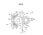
- the fixing unit 20 includes a fixing sleeve 22 as a fixing member fixing a not-yet-fixed image T on the recording medium P; a fixing roller 21 as a supporting member supporting the fixing sleeve 22; an induction heating part 30 as a heating member heating the fixing sleeve 22; and a pressing roller 23 as a pressing member pressing the fixing sleeve 22.
- the fixing sleeve 22 is obtained from forming, on a base layer made of a metal material having a thickness of 30 through 50 ⁇ m, an elastic layer and a releasing layer in sequence, and has an outer diameter of 40 mm.
- a material of the base layer of the fixing sleeve 22 a magnetic metal material such as iron, cobalt, nickel, or an alloy thereof may be used.
- the elastic layer of the fixing sleeve 22 is made of an elastic material such as silicone rubber, and has a thickness of 150 ⁇ m. Thereby, heat capacity is not so much, and it is possible to obtain a satisfactorily fixed image having no fixing unevenness.
- the releasing layer of the fixing sleeve 22 is formed as a result of a fluorine compound such as PFA being coated to have a tube-like shape, and has a thickness of 50 ⁇ m.
- the releasing layer is provided for the purpose of providing toner releasing performance on the surface of the fixing sleeve 22 that directly comes into contact with the toner image (toner) T.
- the fixing roller 21 is formed as a result of forming a heat-resistant elastic layer 21b made of a silicone foam on a cylindrical core metal 21a made of a metal material such as stainless steal, and has an outer diameter of approximately 40 mm.
- the elastic layer 21b of the fixing roller 21 has a radial thickness of 9 mm, and is formed to have Asker C hardness on its axis of 30 through 50 degrees.
- the fixing roller 21 comes into contact with the inner circumferential surface of the fixing sleeve 22, and maintains the fixing sleeve 22 of a thin thickness to have a roller-like shape.
- the pressing roller 23 is formed as a result of forming a heat-resistant elastic layer 23b made of a silicone rubber or such and a releasing layer (not shown) in sequence on a core metal 23a made of a highly thermal conductive metal material such as aluminium or copper, and has an outer diameter of 40 mm.
- the elastic layer 23b is formed to have a radial thickness of 2 mm.
- the releasing layer is formed as a result of coating a PFA tube, and is formed to have a thickness of 50 ⁇ m.
- the pressing roller 23 is pressed onto the fixing roller 21 via the fixing sleeve 22, and forms a nip part at the point of thus being pressed.
- the recording medium P is conveyed to the nip part.
- the induction heating part 30 includes an exciting coil 31, a core part 32 and a demagnetizing coil 33.
- the exciting coil 31 is formed as a result of a litz wire in which fine wires are bound being wound on a coil guide disposed to cover a part of the outer circumferential surface of the fixing sleeve 22 to extend along a width direction (i.e., a direction perpendicular to the drawing of FIG. 2 ).
- the demagnetizing coil 33 is disposed symmetrically to have a physical relationship corresponding to a recording-medium-width direction and is disposed to be superposed on the exciting coil 31.
- the core part 32 is made of a ferromagnetic material (having relative permeability on the order of 2500) such as ferrite, and has a center core 32b and a side core 32a provided to form efficient magnetic fluxes toward the fixing sleeve 22.
- the core part 32 is disposed to face the exiting coil 31 extending in the width direction.
- the fixing unit 20 configured as described above operates as follows:
- a high-frequency alternating electric current of 10 kHz through 1 MHz (preferably, 20 kHz through 800 kHz) is flown in the exciting coil 31 by a power source part (not shown), and thereby magnetic lines of force are formed near the fixing sleeve 22 facing the exciting coil 31 and switched alternately between both directions.
- a power source part not shown
- magnetic lines of force are formed near the fixing sleeve 22 facing the exciting coil 31 and switched alternately between both directions.
- the fixing sleeve 22 is heated through induction heating of the base thereof.
- the surface of the fixing sleeve 22 heated through the induction heating reaches the nip part between the fixing sleeve 22 and the heating roller 23. Then, the not-yet-fixed toner image T (toner) on the recording medium P being conveyed is heated and melted.
- the recording medium P carrying the toner image formed through the above-described image forming process is guided by a guide plate 24 and is sent to and inserted between the fixing sleeve 22 and the pressing roller 23 (as a result of the recording medium P moving in a conveyance direction indicated by an arrow Y1). Then, the toner image T is fixed to the recording medium P by the heat given by the fixing sleeve 22 and the pressure given by the pressing roller 23, and the recording medium P is sent out from the nip part as being separated from the fixing sleeve 22 by a fixing separation plate 25 and a pressing separation plate 26. The surface of the fixing sleeve 22 thus having passed through the nip part then reaches at the position facing the induction heating part 30 again.
- a control part such as a CPU mounted in the image forming apparatus according to the first embodiment of the present invention acts as a gradation processing part carrying out gradation processing on image information, and a fixing temperature changing part changing a fixing target temperature at a time of a fixing process.
- a fixing target temperature at a time of a fixing process means a fixing target temperature at a time when the recording medium is passing through the fixing nip (i.e., the recording medium is passing or the plural recording media are successively passing through the fixing nip), from when the supply of the recording medium is started to when the supply of the recording medium is finished, and does not mean a starting-up temperature or such to which the fixing member is heated before the supply of the recording medium is started.
- the dither method is a method where a gradation image is expressed by two values (i.e., black and white). This method is similar to common binarization, and as a result of using the threshold of the binarization which is changed appropriately, it can be seen when viewed from a distance as if gradation between black and white exists although it is binary.
- the error diffusion method is such a type of method of smoothly expressing an image through halftone processing. In this method, an error occurring from processing of a pixel of a digital image is assigned to peripheral pixels, after that the processing is continued also considering an influence of the error having been assigned, and thus, the error is minimized as a whole.
- the fixing target temperature is set at three levels, and the fixing temperature changing part selects a temperature at any one of the three levels.
- the setting of the fixing target temperature is carried out where the fixing target temperature is set to a value such that no problem such as a fixing failure occurs even for a case where such a type of an image which is most disadvantageous for being fixed onto a recording medium is fixed onto a recording medium, as long as the type of the recording medium is not changed.
- the fixing target temperature that is set in a case of the most disadvantageous type of an image is set as a normal temperature (first fixing target temperature).
- the fixing target temperature slightly reduced from the normal temperature is set as a level 1 temperature (second fixing target temperature), and the fixing target temperature considerably reduced from the normal temperature is set as a level 2 temperature (third fixing target temperature).
- the level 1 temperature is set lower than the normal temperature by 5°C
- the level 2 temperature is set lower than the normal temperature by 10°C.
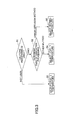
- step S2 a further determination is carried out as to a type of gradation processing used for image forming.
- a type of gradation processing used for image forming step S2
- the normal temperature that is the usual fixing target temperature is selected (step S5).
- step S4 the level 1 temperature is selected.
- selection of the fixing target temperature is thus carried out.
- the above-described process of FIG. 3 is carried out for each sheet of the recording media, and the fixing target temperature is selected for each of the recording media.
- the gradation processing to use is changed between a case of carrying out printer output where image information received from an external apparatus such as a personal computer is output and a case of carrying out copy output where image information read from an original image is output through a copying function.
- the dither method is used in a case of printer output
- the error diffusion method is used for a case of copy output.
- plural image forming modes in which at least one of resolution of an image to be fixed onto a recording medium and the number of levels of size of image dot diameter depending on the purpose are prepared to be set.
- a change of resolution of an image is carried out by changing the number of dots per unit area.
- the image forming modes in printer output includes a speed-preferred general document mode; an image-quality-preferred general document mode; a photograph (image quality preferred) mode; and a high resolution mode.
- Resolution and the number of levels of size of image dot diameter are set as: 600 dpi and 1 bit for the speed-preferred general document mode; 600 dpi and 2 bits for the image-quality-preferred general document mode; 600 dpi and 4 bits for the photograph (image quality preferred) mode; and 1200 dpi and 1 bit for the high resolution mode.
- the speed-preferred general document mode is a mode advantageous to productivity. Jagged shapes may be conspicuous in characters/letters or lines, because the number of lines is small, but a time required for image processing is short.
- a dispersion-type dithering is used for a character/letter area, and the number of lines is large in comparison to the speed-preferred general document mode.
- this mode in comparison to the speed-preferred general document mode, generation of jagged shapes of charters/letters is suppressed, line-screen-type dithering is used for a photograph area, and the mode is advantageous to color shading.
- productivity for example, a time required from when image data is input to when printing thereof is completed
- productivity for example, a time required from when image data is input to when printing thereof is completed
- the photograph mode is a mode in which the number of lines is larger for a photograph area than that of the image-quality-preferred general document mode, the image has higher resolution and graininess is improved.
- the high resolution mode is a mode where the number of lines is larger than that of the photograph (image-quality-preferred) mode in each of a photograph area and a character/letter area, this mode has the highest resolution in the second embodiment and has sharpness of characters/letters or line drawings.
- Switching between the respective modes is carried out by the user using a control panel provided on the apparatus body. Further, a paper type detection part that detects a type of paper (recording medium) may be provided, and switching between the respective modes may be carried out based on the detected type of paper.
- an area detection part is provided to detect a character/letter area and a photograph area of an image, and the type of the dither method and the number of lines are changed for each of the above-mentioned four image forming modes based on the detection result of the area detection part (whether a character/letter area or a photograph area).
- FIG. 4 shows the type (i.e., "concentration type", "line screen type” or "dispersion type") of the dither method and a specific example of the number of lines (150 [1pi], 200 [1pi], 250 [1pi], 300 [1pi] or 600 [1pi]) for each mode.
- fixing performance i.e, performance of fixing a toner image onto a recording medium
- fixing performance of a halftone image differs much depending on the type of the dither method to be used. Below, this point will be described.
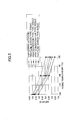
- FIG. 5 shows the fixing performance of a halftone image with respect to the respective types of dithering.
- halftone images are output using respective types of the gradation processing method.
- 11 samples for different image densities of halftone images are prepared where the respective values of the 11 image densities (ID) include those from 0.5 through 1.0 in density in units of 0.05 therebetween measured by X-rite 938 made by X-Rite, Incorporated.
- ID 11 image densities
- the fixing temperatures for the samples three conditions, i.e., 130°C, 140°C and 150°C are prepared.
- the smear fixing performance is one of fixing performance judgment method for copy/printer images, and a method of evaluating how easily toner is removed from a printed halftone image. A specific measuring method will be described now.
- a halftone sample having a base density (ID) of 0.75 ⁇ 0.1 measured by a spectral densitometer made by X-Rite, Incorporated is rubbed 5 times in a going and returning manner by a white cotton cloth with a certain load, and the density of the white cotton cloth at which the toner adheres as a result is measured by the spectral densitometer. Then, it is determined that as the density on the white cotton cloth is higher, the toner is more easily removed, and the fixing performance is worse. At this time, the highest value of the smear ID value from among the samples of the same fixing temperature and the same image processing information is used as a smear ID value of the fixing performance in this gradation processing.
- the smear ID values of the fixing performance in the gradation processing are plotted for the various types of gradation processing with the ordinate of the smear ID value and the abscissa of the fixing temperature as shown in FIG. 5 .
- the fact that the smear ID is larger means that the fixing performance is worse.
- the fixing performance is better than that of the error diffusion method for copy output.
- the fixing performance is worse than that of the case of copy output.
- the result of the fixing performance cannot be determined simply from a single factor such as whether printing output is printer output or copy output. Therefore, it is preferable to carry out control of the fixing temperature to match the fixing performance of each of output images.
- the fixing target temperature is changed based on the type of dithering and the number of lines in a case where the dither method is used as gradation processing.
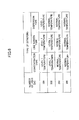
- FIG. 6 shows the fixing target temperature to be selected according to the type of dithering and the number of lines in a case where the dither method is used as a gradation processing method, based on the study result from the graph of FIG. 5 .
- the normal temperature and the level 1 temperature are the fixing target temperatures the same as those mentioned above.
- setting is carried out in such a manner that up to the number of lines of 200 [1pi], the fixing target temperature is reduced to the level 1 temperature.
- setting is carried out in such a manner that for the number of lines of 200 [1pi] or more, the fixing target temperature is not reduced from the normal temperature at any time.
- FIG. 7 shows the fixing target temperatures for each of the image forming modes, with respect to a photograph area and a character/letter area, and whether a halftone image part is included, based on FIGS. 4 and 6 .
- the fixing target temperature is set to any one of the three levels, i.e., the normal temperature, the level 1 temperature and the level 2 temperature.
- steps S1 and S2 are the same as steps S1 and S2 in the flowchart of FIG. 3 according to the first embodiment. Therefore, duplicate description therefor will be omitted, and only points different from the first embodiment will be described.
- the type of the dither method is determined (step S13).
- the normal temperature is selected (step S17) since the dispersion-type dithering is disadvantageous to the fixing performance in comparison to the other types of dithering (concentration-type dithering and line-screen-type dithering) even when the number of lines is the same, and thus, the fixing target temperature cannot be reduced.
- the number of lines is determined (step S14).
- the level 1 temperature slightly reduced from the normal temperature is selected (step S 18) since this case is relatively advantageous to the fixing performance.
- the normal temperature is selected (step S 19) since this case is disadvantageous to the fixing performance.
- the formed image is a monochrome image or a color image, and also whether a character/letter area and/or a photograph area exist, and the fixing target temperature is selected.
- the control method for the fixing target temperature according to the third embodiment will be described. It is noted that also in the third embodiment, the same as the above-mentioned respective embodiments, the fixing target temperature is set to any one of the normal temperature, the level 1 temperature and the level 2 temperature.
- step S21 it is determined whether the input image information is for printer output or copy output (step S21). Also in the third embodiment, the same as the above, the dither method is used in a case of printer output and the error diffusion method is used in a case of copy output. That is, the type of gradation processing is determined by determining whether the printer output or copy output is carried out. As a result, in a case where copy output is carried out, the error diffusion method is used, therefore it is not possible to reduce the fixing target temperature the same as the above, and the normal temperature is selected (step S23). It is noted that even in the case where the error diffusion method is used as a gradation processing method, it is also possible to carry out controlling of the fixing target temperature depending on sizes of dots and/or whether a halftone image part is included.
- step S22 it is determined whether the image is a monochrome image or a color image. Since the dither method is used in a case of a monochrome image, it is then determined by obtaining image processing information 1 described next (see FIG. 10 ) whether it is possible to reduce the fixing target temperature from the normal temperature according to the type of the dithering and the number of lines. This is because the fixing target temperature of a monochrome is determined according to the smear fixing performance, and there is an image having the small number of isolated dots depending on the type of dithering such as the line-screen-type dithering, the concentration-type dithering or such. Therefore, the fixing target temperature may be able to be reduced in a case where the number of isolated dots is small and the image is advantageous to the smear fixing performance for halftone.
- the dither method is used as a gradation processing method also in the case of a full-color image.
- a toner adhesion amount is large and rather solid rendering performance or cold offset becomes a critical condition than the smear fixing performance, and thus, according to the third embodiment, the fixing target temperature is not reduced for full-color images.
- the normal target temperature is selected (step S23). It is possible to add a control of changing the fixing target temperature depending on a toner adhesion amount or such also in cases of full-color images.
- step S24 in a case of a monochrome image (step S24), image processing information I is obtained, and it is determined whether it is possible to reduce the fixing target temperature from the normal temperature. This process will now be described.
- step S31 it is determined from the image processing information 1 whether the image is carried out in a normal mode or a high resolution mode.
- the high resolution mode is the same as the above-mentioned high resolution mode and the normal mode means each of the above-mentioned respective modes other than the high resolution mode (i.e., the speed-preferred general document mode, the image-quality-preferred general document mode or the photograph mode (see FIG. 4 )).
- the determination in step S31 is carried out according to which one of the above-mentioned four image forming modes is selected by the user, for example.
- the normal temperature is selected (step S33) since the number of lines is large in this case. It is noted that even in a case of the high resolution mode, such a control may be carried out that it is determined whether a halftone image part is included or so, and the fixing target temperature may be reduced in a case whether no halftone image part is included.
- step S32 of FIG. 10 in a case of the normal mode (step S32 of FIG. 10 ), the image processing information 2 is obtained and it is determined whether the fixing target temperature can be reduced.
- step S41 it is determined whether a character/letter area exists. In a case where a character/letter area exists, it is determined whether the character/letter area includes an image of less than 100% (i.e., a halftone image part) (step S42). In a case where an image of less than 100% is included in the character/letter area, further it is determined whether the speed-preferred general document mode is used (step S43).
- the concentration-type dithering is used, and in a case of any one of the other image-quality-preferred general document mode and the photograph mode, the dispersion-type dithering is used for character/letter areas (see FIG. 4 ). Therefore, in a case where the image includes a character/letter area, the character/letter area includes an image of less than 100%, and the speed-preferred general document mode is used, the concentration-type dithering where there are few isolated dots is used. Therefore, in this case, the level 1 temperature is selected (step S45) since it is possible to somewhat reduce the fixing target temperature.
- the fixing target temperature is not reduced and the normal temperature is selected (step S44).
- step S46 it is determined (step S46) whether the image includes a photograph area. Then, in a case where it is determined that the image includes a photograph area, it is determined whether the photograph area includes an image of less than 100% (step S47). Then, in a case where the image includes a photograph area and the photograph area includes an image of less than 100%, the line-screen-type dithering may be used the same as the above (see FIG. 4 ). Therefore, there may be few isolated dots, and thus, it is possible to somewhat reduce the fixing target temperature. Therefore, the level 1 temperature is selected (step S48).
- step S46 determines whether the image includes no photograph area or it is determined in step S47 that a photograph area does not include an image of less than 100%
- the level 2 temperature is selected (step S49).
- no halftone image exists, and thus, the image is a 100% solid image. Therefore, the margin for the fixing performance is large, and it is possible to considerably reduce the fixing target temperature.
- steps S42 and S47 of determining whether an image of less than 100% is included are carried out using the CMYK values of the image.
- a low-temperature-fixing toner may be used as the black toner in any one of the above-mentioned embodiments of the present invention.
- FIG. 12 is a flowchart of the control method for the fixing target temperature according to the fourth embodiment of the present invention.
- the fixing target temperature is selected from four levels, and a fixing target temperature changing part selects any temperature of the four levels.
- the fixing target temperature for a case of a full-color image which is most disadvantageous to the fixing performance is set as a normal temperature (first fixing target temperature).
- first fixing target temperature In a case of a monochrome image, it is possible to set the fixing target temperature lower than that of a case of a full-color image.
- a level 1 temperature slightly reduced from the normal temperature of a case of a full-color image
- a level 2 temperature slightly reduced from the level 1 temperature
- a level 3 temperature (fourth fixing target temperature) considerably reduced from the level 1 temperature
- the level 1 temperature is set to a temperature lower than the normal temperature by 10°C
- the level 2 temperature is set to a temperature lower than the normal temperature by 15°C
- the level 3 temperature is set to a temperature lower than the normal temperature by 25°C.
- step S51 it is determined (step S51) whether an image to be formed on a recording medium is a monochrome image or a full-color image.
- the normal temperature is selected as mentioned above (step S57).
- step S52 a determination in step S52 is carried out since it is possible to reduce the fixing target temperature.
- step S52 it is determined whether halftone processing of the image is carried out. Further, depending on a result of the determination, after that (step S53) the type of gradation processing used in image forming may be determined.
- the operations in steps S52 and S53 are the same as those in step S1 and S2 in FIG. 3 , and thus, duplicate description will be emitted.
- the fourth embodiment shown in FIG. 12 is different in that the normal temperature, the level 1 temperature and the level 2 temperature selected as results of steps S1 and S2 of FIG. 3 become the level 1 temperature, the level 2 temperature and the level 3 temperature, respectively, at a time of forming a monochrome image, as shown.
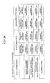
- FIGS. 13A and 13B show the fixing target temperatures for each of the image forming modes at a time of printing full-color image ( FIG. 13A ) and at a time of printing a monochrome image ( FIG. 13B ) depending on a photograph area and a character/letter area, and whether a halftone image part is included (an image of less than 100% is included).
- the normal temperature, the level 1 temperature, the level 2 temperature and the level 3 temperature in the fifth embodiment are the same as those in the fourth embodiment described above.
- tables of FIGS. 13A and 13B are produced based on FIGS. 4 and 6 , and settings of the types of dithering and the number of lines for the respective image forming modes in FIGS. 13A and 13B are the same as those mentioned above.
- FIG. 14 is a flowchart of the control method according to the fifth embodiment of the present invention.
- step S61 in the control of the fixing target temperature according to the fifth embodiment, first it is determined in step S61 whether an image to be formed on a recording medium is a monochrome image or a full-color image.
- the normal temperature is selected as mentioned above (step S66).
- step S66 the normal temperature is selected as mentioned above (step S66).
- step S62 determinations in steps starting from step S62 are carried out since it is possible to reduce the fixing target temperature.
- steps S62, S63, S64 and S65 are the same as those in steps S1, S2, S13 and S14 in FIG. 8 , and thus duplicate description will be omitted.
- the fifth embodiment shown in FIG. 14 is different in that the normal temperature, the level 1 temperature and the level 2 temperature selected as results of steps S1, S2, S 13 and S 14 of FIG. 8 become the level 1 temperature, the level 2 temperature and the level 3 temperature, respectively, at a time of forming a monochrome image.
- FIGS. 15 , 16 and 17 are flowcharts of a control method according to a sixth embodiment of the present invention using the low-temperature-fixing black toner.
- the fixing target temperature is selected from the different four levels, i.e., the normal temperature at a time of forming a full-color image and the level 1 temperature, the level 2 temperature and the level 3 temperature at a time of forming a monochrome image.
- step S81 it is determined whether an image to be formed on a recording medium is a monochrome image or a full-color image.
- the normal temperature is selected as mentioned above (step S85).
- step S82 determinations starting from step S82 are carried out since it is possible to reduce the fixing target temperature.
- step S82 it is determined whether the input image information is for printer output or copy output.
- the level 1 temperature is selected (step S84) since the error diffusion method is used and the fixing target temperature cannot be further reduced at a time of forming a monochrome image. It is note that it is possible to carry out control of the fixing target temperature according to the sizes of dots and/or whether a halftone image part is included even in the case of using the error diffusion method as a gradation processing method.
- a process (of FIG. 16 ) of obtaining image processing information 1 and determining whether the fixing target temperature can be reduced from the level 1 temperature is carried out (step S83).
- FIG. 16 shows a flowchart of obtaining the image processing information 1 and selecting the fixing target temperature.
- FIG. 17 shows a flowchart of, after carrying out the process of FIG. 16 , further obtaining image processing information 2, and selecting the fixing target temperature.
- the flowcharts of FIGS. 16 and 17 are the same as those shown in FIGS. 10 and 11 , and duplicate description will be omitted.
- the sixth embodiment shown in FIGS. 16 and 17 is different in that the normal temperature, the level 1 temperature and the level 2 temperature selected in the flowcharts of FIGS. 10 and 11 become the level 1 temperature, the level 2 temperature and the level 3 temperature, respectively, at a time of forming a monochrome image.
- FIG. 18 shows PDL software
- PDL software includes a parser part 301 carrying out syntax analysis (parsing) for each of PDL such as PS, PCL or RPCS of Ricoh; and a rendering core part 302 carrying out image forming of PDL.
- the rendering core part 302 includes a rendering module I/F part 303 that is an I/F receiving text, images, vector graphics and rendering setting information; an intermediate data storing part 304 storing rendering data such as text, images, vector graphics and so forth and the rendering setting information having colors and transparent settings in an intermediate data memory 305; the intermediate data memory 305; and plural rendering process parts 500 carrying out rendering based on the rendering data to generate output image data.
- Dither information 307 to be used is obtained by the PDL parser part 301 from an environment such as a ROM area or such at a time of starting up and is provided to the rendering core part 302.
- Printing data sent to a controller in the image forming apparatus from a driver of a host PC is data of each of jobs as units, one job includes one or more pages, and 1 page includes one or more bands.
- rendering commands and information used for various sorts of settings are included.
- Typical rendering commands include characters/letters, graphics and images. Further, also commands used for setting rendering colors, commands used for setting resolution of a page or such are included in the rendering commands.
- the PDL parser 301 separates the printing data into the rendering commands and so forth, and transfers them to the rendering module I/F 303.
- a used dither determination part 306 receives the information from the rendering module I/F 303, and selects dither IDs from among the dither information 307 previously obtained as mentioned above to be used in this environment, for being to be used for a page, based on depths, resolutions and other settings of the page. Next, rendering colors are set, and a rendering command I/F (not shown) included in the rendering module I/F 303 is called. Then, dithering to be used for coordinates at which rendering is carried out according to the rendering commands is determined up to planes and density values.
- the used dither determination part 306 may be included in the rendering module 303. When the dither IDs, planes and density values are thus determined, the fixing temperature information is also determined, and thus, the fixing temperature information for the rendering commands is obtained.
- FIG. 19 shows one example of a fixing temperature change during successive printing according to any one of the above-mentioned embodiments of the present invention.
- the fixing target temperature is selected for each sheet of the recording media. Therefore, there may be a case where the fixing target temperature is changed during successive printing operations between the normal temperature, the level 1 temperature and the level 2 temperature or between the normal temperature, the level 1 temperature, the level 2 temperature and the level 3 temperature.
- the fixing target temperatures (the normal temperature (normal), the level 1 temperature (level 1) and the level 2 temperature (level 2)) for first through ninth pages on which printing is carried out successively, and a change in the fixing temperature that is changing according to the change in the fixing target temperature are shown.
- the increasing amount in the fixing target temperature from the level 2 temperature to the normal temperature is large. Therefore, it is necessary to increase the fixing temperature sharply to timely follow the fixing target temperature.
- the fixing temperature is controlled during successive printing operations as will be described now.
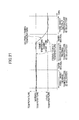
- FIG. 20 shows a change in the (actual) fixing temperature when, as an example, three sheets of recording media are successively processed where the ordinate indicates temperature and abscissa indicates time.
- a long dashed double-short dashed line represents the (actual) fixing temperature
- a solid line represents the fixing target temperature.
- the fixing target temperature selected for the first and second sheets are the same level 2 temperature, and therefore, the fixing target temperature is not to be changed.
- the fixing target temperature selected for the third sheet is the normal temperature. Therefore, it is necessary to increase the fixing temperature by a large amount between the second and third sheets. In such a case where it is necessary to increase the fixing temperature by a large amount between the second and third sheets, a change of the fixing target temperature from the level 2 temperature to the normal temperature is started before the completion of causing the second sheet to pass through the fixing unit (fixing nip).
- the change of the fixing target temperature from the level 2 temperature to the normal temperature is started when the first image forming unit (in the example of FIG. 1 , the process unit 1Y for yellow) among the plural image forming units starts image forming operations on the second sheet of recording medium.
- the first image forming unit in the example of FIG. 1 , the process unit 1Y for yellow
- the surface temperature of the fixing roller as the fixing member has been started to increase from the level 2 temperature to the normal temperature as shown in FIG. 20
- the surface temperature of the fixing roller reaches the normal temperature before the third sheet of recording medium passes through the fixing nip, as shown in FIG. 20 .
- FIG. 21 shows, different from the case of FIG. 20 , a change of the (actual) fixing temperature under the condition where the first and second sheets are output with the normal temperature, and the third sheet is output with the level 2 temperature. It is noted that also in FIG. 21 , a long dashed double-short dashed line represents the (actual) fixing temperature, and a solid line represents the fixing target temperature.
- the fixing target temperature it is necessary to change the fixing target temperature from the normal temperature to the level 2 temperature between the second and third sheets.
- a change of the fixing target temperature is started immediately after the completion of causing the second sheet to pass through the fixing unit (fixing nip), and at a time when causing the third sheet to pass through the fixing nip is started, the fixing temperature has not yet been reduced to the level 2 temperature.
- no problem occurs even when the fixing temperature has not yet been reduced to the level 2 temperature that is the target temperature.
- a start of changing the fixing target temperature is carried out at an earlier timing in comparison to a case where the fixing target temperature of a recording medium for which a fixing process is carried out next is lower than the fixing target temperature of a specific recording medium (for example, in the case of FIG. 21 ).
- the fixing target temperature of a recording medium for which a fixing process is to be carried out next is higher than the fixing target temperature of a specific recording medium.
- the fixing target temperature is changed from the level 2 temperature to the normal temperature between the second and third sheets
- a time required for increasing the fixing temperature is longer since the temperature difference is larger. Therefore, by starting the change at an earlier timing in a case where the difference between the fixing target temperatures is larger, it is possible to timely complete the increase in the fixing temperature.
- the timing at which the change of the fixing target temperature is started has been described using the examples for the temperature change between the level 2 temperature and the normal temperature.
- the timing at which the change of the fixing target temperature is started may be changed in the same way also for the temperature change between the level 3 temperature and the normal temperature or the temperature change between the level 3 temperature and the level 1 temperature, for example.
- FIG. 22 shows a general sectional view of a configuration of another fixing unit applicable to any one of the above-mentioned embodiments of the present invention.
- the fixing unit 50 includes an endless fixing belt 51 fixing a not-yet-fixed image T on a recording medium.
- a metal pipe 52 as a supporting member supporting an inner circumferential surface of the fixing belt 51; a heater 53 as a heating member heating the fixing belt 51; a pressing roller 54 as a pressing member pressing the fixing belt 51 from the outer circumferential side; a nip creating part 55 disposed on the inner circumferential side of the fixing belt 51 and coming into contact with the pressing roller 54 via the fixing belt 51 to form a fixing nip; and an auxiliary stay 56.
- the fixing belt 51 includes a base made of SUS or nickel and a surface layer made of silicone rubber and a surface layer made of PFA coated on the base.
- the metal pipe 52 has a base made of SUS or nickel, and it is preferable to provide a fluorine-based slidable coating on the outer circumferential surface coming into contact with the fixing belt 51.
- the pressing roller 54 includes a core metal made of a metal and an elastic layer made of silicone rubber coated on the outer circumferential surface of the core metal.
- the nip creating part 55 is formed as a result of fluororubber or such being wound by a PTFE sheet or such.
- the heater 53 As a result of the heater 53 generating heat, the metal pipe 52 is heated. Thereby, the temperature of the fixing belt 51, with which the metal pipe 52 is contact, is increased. Then, as a result of the recording medium P on which the not-yet-fixed toner image T is formed passing through the fixing nip between the fixing belt 51 being rotated and the pressing roller 54 in a state where the temperature of the fixing belt 51 has reached the fixing target temperature, the not-yet-fixed image T on the recording medium P is fixed. Further, the fixing belt 51, the temperature of which has been reduced through the fixing operation, is heated again by the heater 53, and this flow is repeated.
- FIG. 23 is a general sectional view of a configuration of yet another fixing unit applicable to any one of the above-mentioned embodiments of the present invention.
- the fixing unit 60 includes a fixing sleeve 61 as a fixing member; a pressing roller 62 as a pressing member pressing the fixing sleeve 61; a nip creating part 63 disposed on the inner circumferential side of the fixing sleeve 61 and coming into contact with the pressing roller 62 via the fixing sleeve 61 to form a fixing nip; a surface-type heating member 64 as a heating member heating the fixing sleeve 61; and a heating member supporting part 65 supporting the surface-type heating member 64 at a certain position.
- the reference numeral 66 denotes a terminal table stay
- the reference numeral 67 denotes a power supply line
- the reference numeral 68 denotes a core supporting member.
- the surface-type heating member 64 is formed as a result of a resistor heating part being disposed in the inside of a deformable film-shaped member. Further, the surface-type heating member is configured to come into contact with the inner circumferential surface of the fixing sleeve 61 and directly heat the fixing sleeve 61. Further, the surface-type heating member 64 may be disposed adjacent to the fixing sleeve 61.
- a not-yet-fixed image T on a recording medium P is fixed as a result of the recording medium P on which the not-yet-fixed toner image T is formed passing through the fixing nip between the fixing sleeve 61 being rotated and the pressing roller 62 in a state where the temperature of the fixing sleeve 61 has reached the fixing target temperature.
- a fixing unit to which any one of the above-mentioned embodiments of the present invention is applicable is not limited to the above-described fixing units.
- a pressing member such as a pressing belt may be used instead of the pressing roller, and a heating member that heats the pressing member may be provided.
- an image forming apparatus to which any one of the above-mentioned embodiments of the present invention is applicable is not limited to the laser printer shown in FIG.
- 1 may be an image forming apparatus such as another type of a printer, a copier, a facsimile machine, a multifunction peripheral having a function of a printer, a copier and a facsimile machine in a combined manner, or such.
- an image forming apparatus such as another type of a printer, a copier, a facsimile machine, a multifunction peripheral having a function of a printer, a copier and a facsimile machine in a combined manner, or such.
- the low-temperature-fixing black toner used in the fourth, fifth and sixth embodiments of the present invention has a required fixing temperature lower than that of color toners by equal to or more than 10°C, contains at least a thermoplastic resin, and contains as the thermoplastic resins at least crystalline polyester resin and noncrystalline polyester resin, a wax and a colorant.
- the low-temperature-fixing black toner has a clear endothermic peak at 50 through 10°C on a differential thermal curve in DSC (Differential Scanning Calorimetry) temperature increase, the melting point of the above-mentioned crystalline polyester is 60°C through 80°C, and the melting point of the wax is 70°C through 90°C.
- the melting point of the crystalline polyester is less than 60°C, degradation in heat resisting storage stability appears, and in a case where the melting point of the crystalline polyester is more than 80°C, degradation in low-temperature fixing performance appears.
- the melting point of the wax is less than 70°C, degradation in heat resisting storage stability appears, and in a case where the melting point of the was is more than 90°C, degradation in low-temperature fixing performance appears.
- the melting points of the crystalline polyester and the wax are lower because of low-temperature fixing performance. However, if the melting points thereof are too low, heat resisting storage stability may be degraded. Further, as to the wax, it is preferable that the melting point is higher than that of crystalline polyester since the wax tends to be degraded in heat resisting storage stability in comparison to crystalline polyester.
- organic solvent one which completely dissolves crystalline polyester resin at high temperature to form a uniform solution, and on the other hand, which is separated from crystalline polyester when being cooled to a low temperature to form an opaque nonuniform solution is preferable.
- organic solvent it is possible to use alone or in a manner of combining two or more of toluene, ethyl acetate, butyl acetate, methyl ethyl ketone, methyl isobutyl ketone and so forth.
- Crystalline polyester resin in the toner shows thermofusion characteristics showing a sharp reduction of viscosity near the fixing start temperature since it has high crystallinity. That is, heat resisting storage stability is satisfactory up to immediately before the melting start temperature due to crystallinity, and at the melting start temperature, a sharp reduction of viscosity (sharp melting characteristics) occurs, and thus fixing is achieved. Therefore, it is possible to design the toner having both satisfactory heat resisting storage salability and low-temperature fixing performance. Further, it has been seen that as to a releasing range (a difference between a fixing lower-limit temperature and a hot-offset occurring temperature), satisfactory result is shown.
- alcohol ingredients saturated aliphatic diol compounds having the carbon number of 2 through 12, for example, 1,4-butane
- crystalline polyester resin by only a saturated diol ingredient having the carbon number of 4 through 12 of any one of 1,4-butanediol, 1,6-hexanediol, 1,8-octanediol, 1,10-decanediol and 1,12-dodecanediol; and a saturated dicarboxylic acid ingredient having the carbon number of 4 through 12 of any one of 1,4-butanedioic acid, 1,6-hexanedioic acid, 1,8-octanedioic acid, 1,10-decanedioic acid and 1,12-dodecanedioic acid.
- a method of controlling the crystallinity and the softening point of crystalline polyester resin a method may be cited of designing and using nonlinear polyester obtained from at a time of synthesizing polyester, adding polyhydric alcohol of equal to or more than trihydric such as glycerin to the alcohol ingredient and/or adding polyvalent carboxylic acid of equal to or more than trivalent such as trimellitic anhydride to the acid ingredient, to carry out condensation polymerization.
- a molecular structure of crystalline polyester resin according to the embodiments of the present invention can be seen by NMR measurement using a solution or a solid, or, other than it, X-ray analysis, GC/MS, LC/MS, IR measurement or such. More easily, one having absorption based on ⁇ CH (out-of-plane bending vibration) of olefin at 956 ⁇ 10 cm -1 or 990 ⁇ 10 cm -1 in infrared ray absorption spectrum may be cited as an example.
- ⁇ CH out-of-plane bending vibration
- the ratio of number average molecular weight of equal to or less than 500 is equal to or more than 0% and equal to or less than 2.0%, and also, the ratio of the above-mentioned crystalline polyester Mn of equal to or less than 1000 is equal to or more than 0% and equal to or less than 4.0%.
- the acid number and the hydroxyl value of crystalline polyester resin according the embodiments of the present invention when A denotes the acid number and B denotes hydroxyl value, satisfy the following formulas: 10 mg KOH / g ⁇ A ⁇ 40 mg KOH / g 0 mg KOH / g ⁇ B ⁇ 20 mg KOH / g 20 mg KOH / g ⁇ A + B ⁇ 40 mg KOH / g
- the acid number is equal to or less than 10 mg KOH/g
- affinity with paper as the recording medium may be degraded, and heat resisting storage stability may be degraded.
- the acid number is equal to or more than 40 mg KOH/g, or the hydroxyl value is equal to or less than 20 mg KOH/g, electrification capability of the toner under high temperature and high humidity may be degraded.
- compatibility with noncrystalline polyester may be degraded, and sufficient low-temperature fixing performance may not be obtained.
- compatibility between crystalline polyester and noncrystalline polyester may be increased too much, and heat resisting storage stability may be degraded.
- solubility of crystalline polyester to organic solvent at 70°C is equal to or more than 10 parts by mass. In a case of less than 10 parts by mass, affinity between organic solvent and crystalline polyester may be poor, it may be difficult to disperse crystalline polyester in organic solvent to a submicron size, crystalline polyester existing in the toner may be nonuniform, and degradation in electrification capability and degradation in image quality may occur when using the toner for a long term.
- solubility of crystalline polyester in organic solvent at 20°C is less than 3.0 parts by mass.
- solubility of crystalline polyester in organic solvent at 20°C is less than 3.0 parts by mass.
- crystalline polyester dissolved in organic solvent may become easily compatible with noncrystalline polyester before being heated, degradation in heat resisting storage stability, contamination of the development unit, and degradation in images may occur.
- the above-mentioned binder resin ingredients contain a binder resin precursor.
- a toner is preferable which is obtained as a result of after dissolving a compound that carries out elongation from or cross-linking with a binder resin precursor into an oil phase obtained from dissolving and dispersing in organic solvent, at least a colorant, a releasing agent, crystalline polyester resin, the above-mentioned binder resin precursor made of modified polyester-based resin, and binder resin ingredients other than these, the above-mentioned oil phase being dispersed into an aqueous medium in which a fine particle dispersing agent exists, to obtain an emulsified dispersion, the above-mentioned binder resin precursor being caused to carry out cross-linking reaction and/or elongation reaction in the emulsified dispersion and the organic solvent being removed.
- a binder resin precursor made of modified polyester-based resin is preferable, and polyester prepolymer modified by isocyanate, epoxy or such may be cited.
- This carries out elongation reaction with a compound (amines or such) having active hydrogen groups, and contributes to improving the releasing range (a difference between a fixing lower-limit temperature and a hot-offset occurring temperature).
- a method of synthesizing the polyester prepolymer it is possible to easily synthesize it by causing a known isocyanate-producing agent or epoxidizing agent to react to polyester resin acting as a base.
- aliphatic polyisocyanate tetramethylene diisocyanate, hexamethylene diisocyanate, 2,6-di(isocyanatomethyl)caproate or such
- alycyclic polyisocyanate isohoron diisocyanate, cyclohexylmethane diisocyanate or such
- aromatic diisocyanate tlylene diisocyanate, diphenylmethane diisocyanate or such
- aromatic aliphatic diisocyanate ⁇ , ⁇ , ⁇ ', ⁇ '-tetramethylxylylene diisocyanate or such
- isocyanurates one obtained from the above-mentioned polyisocyanate being blocked by phenol derivative, oxime, caprolactam or such; and combined usage of two or more thereof
- epichlorohydrin or such may be cited as a typical example.
- a ratio of the isocyanate-producing agent is, as an equivalent ratio [NCO]/[OH] of an isocyanate group [NCO] and a hydroxyl group [OH] of polyester as a base, usually 5/1 through 1/1, preferably 4/1 through 1.2/1, and more preferably 2.5/1 through 1.5/1.
- [NCO]/[OH] exceeds 5
- low-temperature fixing performance may be degraded.
- the molar ratio of [NCO] is less than 1, the urea content of the polyester prepolymer is reduced, and hot-offset resisting performance may be degraded.
- the content of the isocyanate-producing agent in the polyester prepolymer may be usually 0.5 through 40 percent by weight, preferably 1 through 30 percent by weight, and more preferably 2 through 20 percent by weight.
- hot-offset resisting performance may be degraded, and also, it may be disadvantageous to both heat resisting storage stability and low-temperature fixing performance. Further, when more than 40 percent by weight, low-temperature fixing performance may be degraded.
- Isocyanate groups contained per molecule of the polyester prepolymer are usually one or more, preferably 1.5 through 3 on average, and more preferably 1.8 through 2.5 on average. When less than one per molecule, the molecular weight of urea modified polyester resin after elongation reaction may be reduced and hot-offset resisting performance may be degraded.
- the weight average molecular weight of the above-mentioned binder resin precursor is equal to or more than 1 ⁇ 10 4 and equal to or less than 3 ⁇ 10 5 .
- a compound having active hydrogen groups may be cited, and as a typical one thereof, amines may be cited.
- amines diamine compounds, polyamine compounds having trivalent or more, aminoalcohol compounds, aminomercaptan compounds, amino-acid compounds, compounds blocking these amino groups and so forth may be cited.
- aromatic diamine phenyl diamine, diethyltoluene diamine, 4,4' diaminodiphenylmethane and so forth
- alycyclic diamine (4,4'-diamino-3,3' dimethyl dicyclohexylmethane, diamine cyclohexane, isohoron diamine or such)
- aliphatic diamine ethylene diamine, tetramethylene diamine, hexamethylene diamine or such
- polyamine compounds of more than trivalent diethylenetriamine, triethylene tetramine and so forth may be cited.
- aminoalcohol compounds methanol amine, hydroxyethyl aniline and so forth may be cited.
- amino mercaptan compounds aminoethyl mercaptan, aminopropyl mercaptan and so forth may be cited.
- amino acid compounds amino propione acid, amino caproic acid and so forth may be cited.
- compounds blocking these amino groups ketimine compounds obtained from the above-mentioned amines and ketones (acetone, methyl ethyl ketone, methylisobutyl ketone and so forth), oxazoline compounds and so forth may be cited.
- Preferable ones of these amines are diamine compounds, and mixtures of diamine compounds and few amounts of polyamine compounds.
- colorant of the embodiments of the present invention all of known dyes and pigments can be used, and for example, carbon black, nigrosin dye, iron black, naphthol yellow S, hansa yellow (10G, 5G, G), cadmium yellow, yellow iron oxide, yellow ochre, chrome yellow, titanium yellow, polyazo yellow, oil yellow, hansa yellow (GR, A, RN, R), pigment yellow L, benzidine yellow (G, GR), permanent yellow (NCG), vulcan fast yellow (5G, R), tartrazinelake, quinoline yellow lake, anthrazan yellow BGL, isoindolinone yellow, red iron oxide, red lead, lead vermilion, cadmium red, cadmium mercury red, antimoniy vermilion, permanent red 4R, para red, fire red, parachloroorthonitro anilin red, lithol fast scarlet G, brilliant fast scarlet, brilliant carmine BS, permanent red (F2R, F4R, FRL, FRLL and F4R
- the colorant used in the embodiments of the present invention may be used as a master batch mixed with resin.
- binder resin which is to be used in manufacturing the master batch or kneaded together with the master batch include the above-mentioned modified or unmodified polyester resins; styrenes and polymers of substituted products thereof, such as polystyrenes, poly-p-chlorostyrenes, polyvinyltoluenes and so forth; styrene-based copolymers such as styrene-p-chlorostyrene copolymers, styrene-propylene copolymers, styrene-vinyltoluene copolymers, styrene-vinylnaphthalene copolymers, styrene-methyl acrylate copolymers, styrene-ethyl acrylate copolymers, styrene-butyl acrylate cop
- the master batch may be prepared by mixing and kneading a colorant and a resin prepared for the master batch through application of high shearing force.
- an organic solvent may be used for the purpose of improving interaction between the colorant and the resin.
- a so-called flashing method may be preferably used where an aqueous paste containing the colorant and water is mixed and kneaded with the resin and the organic solvent, thus the colorant is caused to transfer to the resin, and the moisture and the organic solvent ingredient are removed, since the wet cake of the colorant can be directly used (i.e., no drying is required to be performed).
- a high-shearing disperser e.g., three-roll mill or such is preferably used.
- the releasing agent is preferably a wax having a melting point of 50 through 120°C.
- the melting point of the wax may be obtained using a TG-DSC system TAS-100 (Rigaku Corporation) as a differential scanning calorimeter, and measuring the endothermic maximum peak.
- any one of the following materials may be used.
- waxes vegetable-based waxes such as carnauba wax, a cotton wax, a Japan wax, a rice wax and so forth; animal-based waxes such as bees wax, lanolin and so forth; mineral-based waxes such as ozokerite, cersin and so forth; petroleum waxes such as paraffin, microcrystalline, petrolatum and so forth, and so forth may be cited. Further, as releasing agents other than these natural waxes, synthesized hydrocarbon waxes such as a fischer-tropsch wax, a polyethylene wax and so forth; synthesized waxes such as ester, ketone, ether and so forth, and so forth may be cited.
- fatty amides such as 1,2-amide hydroxystearate, amide stearate, imide phthalic anhydride, chlorinated hydrocarbon and so forth; and as crystalline polymers having low molecular weight, crystalline polymers having long chain alkyl groups on side chains such as homopolymers or copolymers (for example, n-stearyl acrylate-ethyl methacrylate copolymers and so forth) of poly n-stearyl methacrylate, poly n-lauryl methacrylate and so forth, may be used as the releasing agents.
- the toner of the embodiments of the present invention may optionally contain an electrification control agent.
- electrification control agents all of those known as electrification control agents may be used, for example, nigrosin-based dyes, triphenylmethane-based dyes, chrome-containing metal complex dyes, chelate molybdate dyes, rhodamine-based dyes, alkoxy-based amines, quaternary ammonium salts (including fluorine-modified quaternary ammonium salts), alkyl amides, phosphor used alone or as compounds, tungsten used alone and as compounds, fluorine-based activators, salicylate metal salts, metal salts of salicylate derivatives, and so forth.
- a nigrosin-based dye Bontron 03; a quaternary ammonium salt: Bontron P-51; a metal-containing azo dye: Bontron S-34; an oxynaphtoic acidbased metal complex; E-82, a salicylic acid based metal complex: E-84; phenol based condensation product: E-89 (the above-mentioned products being made by ORIENT CHEMICAL PINSTRIPED CO., LTD); quaternary ammonium salt molybdenum complexes; TP-302, TP-415 (the above-mentioned products being made by HODOGAYA CHEMICAL CO., LTD.); a quaternary ammonium salt: COPY CHARGE PSY VP2038; a triphenylmethane derivative: COPY BLUE PR; quaternary ammonium salts: COPY CHARGE NEG VP2036, COPY CHARGE NX VP434 (the above-
- the amount to use the electrification control agent is determined by the type of the binder resin, whether additives optionally used are used and the toner manufacturing method including the dispersion method, and thus, is not uniquely limited.
- the electrification control agent is used in a range of 0.1 through 10 parts by weight for 100 parts by weight of the binder resin. A range of 0.2 through 5 parts by weight is more preferably. In a case where 10 parts by weight is exceeded, the electrification performance of the toner is to large, the effect of the main electrification control agent is reduced, the electrostatic attraction force with the development roller is increased, and thus, reduction in flowability of the developer and/or reduction in the image density may occur.
- the electrification control agent may be dissolved and dispersed after being melted and kneaded together with the master batch and resin.
- the electrification control agent may be added at the time of direct dissolution and dispersion in the organic solvent, or may be fixed to the toner surfaces after the toner particles are produced.
- non-crystalline, unmodified polyester resins are used as the above-mentioned binder resin ingredients.
- the unmodified polyester resin and the modified polyester resin obtained from the binder resin precursor made of the modified polyester based resin being caused to carry out cross-linking and/or expansion reactions are preferably dissolved in each other at least part thereof.
- polyols and carboxylic acids in the modified polyester resin and the unmodified polyester resin have similar compositions.
- the non-crystalline polyester resin used in the crystalline polyester dispersion may be used if the non-crystalline polyester resin is unmodified.
- the acid value of the crystalline polyester is A and the acid value of the unmodified polyester resin is C, it is preferable that the following relationship is satisfied: - 10 mg KOH / g ⁇ A - C ⁇ 10 mg KOH / g
- compatibility and affinity between the crystalline polyester and the nonpolyester may be poor, and the low-temperature fixing performance may be inferior. Further, the crystalline polyester may become likely to be exposed on the toner surfaces, and contamination of the development unit and filming may be likely to occur.
- urea modified polyester resin may be used in combination with polyester resin modified by chemical bond other than urea bond, for example, polyester resin modified by urethane bond, in addition to unmodified polyester resin.
- the modified polyester resin may be manufactured by a one-shot process or such.
- polyester resin having hydroxyl groups is obtained.
- the polyester resin having the hydroxyl groups and polyisocyanate are reacted at 40 through 140°C, and polyester prepolymer having isocyanate groups is obtained.
- the polyester prepolymer having the isocyanate groups and amines are reacted at 0 through 140°C, and urea modified polyester resin is obtained.
- the number average molecular weight of urea modified polyester resin is usually 1000 through 10000, and is preferably 1500 through 6000.
- solvents may be used optionally.
- solvents ones inactive to isocyanate groups such as aromatic solvents (toluene, xylene and so forth); ketones (acetones, methyl ethyl ketones, methyl isobutyl ketones and so forth); esters (ethyl acetates and so forth); amides (dimethyl formamides, dimethyl acetamides and so forth); ethers (tetrahydrofuranes and so forth) and so forth may be cited.
- aromatic solvents toluene, xylene and so forth
- ketones acetones, methyl ethyl ketones, methyl isobutyl ketones and so forth
- esters ethyl acetates and so forth
- amides dimethyl formamides, dimethyl acetamides and so forth
- ethers tetrahydrofuranes and so forth
- polyester resin having the hydroxyl groups may be mixed in the solution of urea modified polyester resin after the reaction.
- binder resin ingredients to be contained in the oil phase in the embodiments of the present invention crystalline polyester resin, non-crystalline polyester resin, binder resin precursor and unmodified resin may be used in combination. Further, it is also possible to contain binder resin ingredients other than these resins.
- binder resin ingredients it is preferable to contain polyester resins, and it is further preferable to contain polyester resins by equal to or more than 50 percent by weight. If the content of polyethylene resins is less than 50 percent by weight, the low-temperature fixing performance may be degraded. It is especially preferable that all of the binder resin ingredients are polyester resins.
- polyester resins other then polyester resins, styrenes or polymers of styrene substitution products such as polystyrene, poly(p-chlorostyrene), polyvinyltoluene and so forth; styrene-based copolymers such as styrene-p-ohlorostyrene copolymer, styrene-propylene copolymer, styrene-vinyltoluene copolymer, styrene-vinylnaphthalene copolymer, styrene-methyl acrylate copolymer, styrene-ethyl acrylate copolymer, styrene-butyl acrylate copolymer, styrene-octyl acrylate copolymer, styrene-methyl methacrylate copolymer, styrene-e
- water may be used alone or water and a water-miscible solvent are used in combination.
- a water-miscible solvent include, but are not limited to, alcohol (methanol, isopropanol, ethylene glycol and so forth), dimethylformamide, tetrahydrofuran, cellosolves (methyl cellosolve and so forth), lower ketones (acetone, methyl ethyl ketone and so forth), and so forth.
- the binder resin precursor, colorant, releasing agent, crystalline polyester dispersion, electrification control agent, unmodified polyester resin and so forth, forming the toner particles may be mixed when the dispersing elements are formed in the aqueous medium.
- the mixture is added to the aqueous medium and is dispersed.
- the other toner raw materials such as the colorant, releasing agent, electrification control agent and so forth are not necessarily mixed previously when the particles are formed in the aqueous medium, and may be added after the particles are formed.
- the colorant may be added by a known dyeing method.
- the dispersion although is not limited to, know equipment such as one of a low-speed shearing type, a high-speed shearing type, a frictional type, a high-pressure jet type, or an ultrasonic type, for example, may be used.
- the one of high-speed shearing type is preferable to obtain the particles of the dispersing elements having a particle diameter of 2 through 20 ⁇ m.
- the revolution may be usually 1,000 through 30,000 rpm, and preferably 5,000 through 20,000 rpm.
- the dispersing time is not particularly limited to, the dispersing time may be usually 0.1 through 60 minutes in a case where a batch system is used.
- the temperature at a time of the dispersion may be usually 0 through 80°C (under pressure), and preferably, 10 through 40°C.
- the amount of the aqueous medium to use with respect to 100 parts by weight of the toner composition is usually 100 through 1000 parts by weight.
- the amount of the aqueous medium is less than 100 parts by weight, the dispersion condition of the toner composition may not be satisfactory, and the toner having a desired particle diameter may not be obtained.
- the amount of the aqueous medium exceeds 1000 parts by weight, it may be disadvantageous from an economical viewpoint.
- the dispersing agent narrows the size distribution of the resulting toner and stabilizes the dispersion.
- the compound having the active hydrogen groups may be added and be caused to react before the toner composition is dispersed in the aqueous medium, or the compound having the active hydrogen groups may be added after the dispersion in the aqueous medium and reaction may be caused to occur from the particle interfaces.
- polyester modified by polyester prepolymer is produced preferentially on the produced toner surfaces and it is possible to provide a concentration gradient in the inside of the particles.
- anionic surfactants such as alkylbenzene sulfonate, ⁇ -olefin sulfonate and phosphate
- amine-salt-type cationic surfactants such as alkylamine salts, amino alcohol fatty acid derivative, polyamine fatty acid derivative and imidazoline
- quaternary-ammonium-salt-type cationic surfactants such as alkyl trimethyl ammonium salt, dialkyl dimethyl ammonium salt, alkyl dimethyl benzyl ammonium salt, pyridinium salt, alkyl isoquinolinium salt, and benzethonium chloride
- nonionic surfactants such as fatty acid amide derivative, polyvalent alcohol derivative and so forth
- ampholytic surfactants for example, alanine, dodecyl di(aminoethyl)glycine
- surfactants having fluoroalkyl groups which will be preferably used, fluoroalkyl carboxylic acid having the carbon number of 2 through 10 and metal salt thereof, perfluorooctane sulfonyl glutamic acid disodium, 3-[omega-fluoroalkyl(C6 through C11)oxy]-1-alkyl(C3 through C4) sulfonic acid sodium, 3-[omega-fluoroalkanoyl(C6 through C8)-N-ethylamino]-1-propane sulfonic acid sodium, fluoroalkyl(C11 through C20)carboxylic acid and metal salt thereof, perfluoroalkyl carboxylic acid(C7 through C13) and metal salt thereof, perfluoroalkyl(C4 through C12)sulfonic acid and metal salt thereof, perfluor
- SURFLON S-111, S-112, and S-113 made by AGC Seimi Chemical Co., Ltd.
- FLUORAD FC-93, FC-95, FC-98, and FC-129 made by Sumitomo 3M
- UNIDYNE DS-101 and DS-102 made by Daikin Industries, Ltd.
- MEGAFACE F-110, F-120, F-113, F-191, F-812, and F-833 made by DIC Corporation
- EFTOP EF-102, 103, 104, 105, 112, 123A, 123B, 306A, 501, 201, and 204 made by Mitsubishi Materials Electronic Chemicals Co., Ltd.
- FTERGENT F-100 and F-150 made by Neos Company Limited
- cationic surfactants aliphatic primary, secondary, or tertiary amine acids having fluoroalkyl groups; and aliphatic quaternary ammonium salts such as perfluoroalkyl(C6 through C10)sulfonamide propyl trimethyl ammonium salt, benzalkonium salt, benzethonium chloride, pyridinium salt, imidazolinium salt and so forth may be cited.
- SURFLON S-121 (made by AGC Seimi Chemical Co., Ltd.); FLUORAD FC-135 (made by Sumitomo 3M); UNIDYNE DS-202 (made by Daikin Industries, Ltd.); MEGAFACE F-150 and F-824 (made by DIC Corporation); EFTOP EF-132 (made by Mitsubishi Materials Electronic Chemicals Co., Ltd.); and FTERGENT F-300 (made by Neos Company Limited), and so forth may be cited.
- tricalcium phosphate calcium carbonate, titanium oxide, colloidal silica, hydroxyapatite, and so forth may be used.
- dispersion liquid droplets may be stabilized.
- (meth)acryl-based monomers containing acids such as acrylic acid, methacrylic acid, ⁇ -cyanoacrylic acid, ⁇ -cyanomethacrylic acid, itaconic acid, crotonic acid, fumaric acid, maleic acid, maleic anhydride and so forth, or containing hydroxyl groups, for example, ⁇ -hydroxyethyl acrylate, ⁇ -hydroxyethyl methacrylate, ⁇ -hydroxypropyl acrylate, ⁇ -hydroxypropyl methacrylate, ⁇ -hydroxypropyl acrylate, ⁇ -hydroxypropyl methacrylate, 3-chloro-2-hydroxypropyl acrylate, 3-chloro-2-hydroxypropyl methacrylate, diethylene glycol monoacrylate, diethylene glycol monomethacrylate, glycerin monoacrylate, glycerin monomethacrylate, N-methylo
- the calcium phosphate is to be removed from the particulates by a method of water washing or such after the calcium phosphate is dissolved by acid such as hydrochloric acid.
- the calcium phosphate may be removed by an operation of dissolution by enzyme.
- the dispersing agent In a case of using the dispersing agent, it is possible that the dispersing agent is to be caused to remain on the toner particle surfaces. However, it is preferable from a viewpoint of electrification performance, to clean and remove the dispersing agent after the reaction.
- the solvent by which the polyester obtained from the reaction and the modification of the polyester prepolymer is soluble.
- the solvent is preferable in that the particle size distribution can be narrowed. It is preferable that the solvent is volatile having a boiling point of less than 100°C in that removal thereof becomes easier.
- solvents for example, toluene, xylene, benzene, carbon tetrachloride, methylene chloride, 1,2-dichloroethane, 1,1,2-trichloroethane, trichloroethylene, chloroform, monochlorobenzone, dichloroethylidene, methyl acetate, ethyl acetate, methylethyl ketone, methylisobutyl ketone and so forth may be used, where these may be used alone or in combination.
- aromatic- series-based solvents for example, toluene and xylene, and halogenated hydrocarbons such as methylene chloride, 1,2-dichloroethane, chloroform and carbon tetrachloride, are preferred.
- the content of the solvent is usually 0 through 300 parts, preferably 0 through 100 parts and more preferably 25 through 70 parts, for 100 parts of the polyester prepolymer.
- the solvent is removed from the resultant product under normal pressure or a reduced pressure after the elongation and/or cross-linking reaction.
- the cross-linking reaction time and/or the elongation reaction time is determined depending on the reactivity determined by the combination of the polyester prepolymer and the compound having active hydrogen groups.
- the cross-linking reaction time and/or the elongation reaction time is usually 10 minutes through 40 hours, and preferably 30 minutes through 24 hours.
- the reaction temperature is usually 0 through 100°C, and preferably from 10 through 50°C.
- a known catalyst may be optionally used. Specifically, tertiary amines such as trimethyl amine, imidazole and so forth may be cited.
- a method may be used where the temperature of the entire system is gradually increased, and the organic solvent in the liquid droplets are caused to be completely evaporated and removed.
- the emulsified dispersion may be sprayed to dried atmosphere, the non water soluble organic solvent in the liquid droplets may be completely removed and the toner particulates may be produced, and further, the aqueous dispersion may be evaporated and removed.
- a gas in which air, nitrogen, carbon dioxide gas, combustion gas or such is heated may be used as the dried atmosphere to which the emulsified dispersion is sprayed.
- various sorts of air streams heated to a temperature equal to or more than the boiling point of the used solvent having the highest boiling point, may be generally used.
- the desired quality can be sufficiently obtained through the process within a short time using a spray drier, a belt drier, a rotary kiln or such.
- the particle size distribution may be arranged through a classification operation aiming at a desired particle size distribution.
- particulate part can be removed from the liquid.
- the classification operation may be carried out after the powder obtained after the drying is obtained. However, carrying out the classification operation in the liquid is preferable as doing so has better efficiency. Unwanted particulate part or coarse particles obtained therethrough may be returned to the kneading process and used for forming the particles again. When returning the unwanted particulate part or coarse particles, those particles may be in a wet condition.
- the used dispersing agent may preferably be removed from the obtained dispersion liquid as much as possible.
- the removing may preferably be carried out at the same time with the above-mentioned classification operation.
- Specific methods thereof include a method of giving impact force to the mixture with high-speed-spinning blades; a method of injecting in a high-velocity air stream, accelerating and causing the particles to collide together or the complex particles to collide with an appropriate collision plate, and so forth.
- Examples of devices can be used are Ongmill (made by Hosokawa Micron Corporation), a modified I-type Mill (made by Nippon Pneumatic Mfg. Co., Ltd.) in which its grinding air pressure is decreased, Hybridization System (made by NARA MACHINERY CO., LTD.), Kryptron System (made by Kawasaki Heavy Industries, Ltd.), an automatic mortar, and so forth.
- the toner according to the embodiments of the present invention may contain an external additive to assist the fluidity, development performance or electrification performance.
- inorganic particulates may be preferably used.
- the primary particle diameter of the inorganic particulates is preferably 5 nm through 2 ⁇ m, and especially preferably 5 nm through 500 nm.
- the specific surface area based on the BET method is preferably 20 through 500 m 2 /g.
- the usage ratio of the inorganic particulates is preferably 0.01 through 5 percent by weight and especially preferably 0.01 through 2.0 percent by weight.
- the inorganic particulates include, for example, silica, alumina, titanium oxide, barium titanate, magnesium titanate, calcium titanate, strontium titanate, zinc oxide, tin oxide, siliceous sand, clay, mica, wollastonite, diatomaceous earth, chromium oxide, cerium oxide, red iron oxide, antimony trioxide, magnesium oxide, zirconium oxide, barium sulfate, barium carbonate, calcium carbonate, silicon carbide and silicon nitride.
- Such a fluidizing agent may be subjected to a surface treatment to increase hydrophobicity and prevent deterioration of fluidization performance and electrification performance even under high humidity.
- preferable surface treatment agents include a silane coupling agent, a silylation agent, a silane coupling agent having alkylfluoride groups, an organotitanate-type coupling agent, an aluminum-type coupling agent, silicone oil and modified silicon oil.
- Examples of a cleaning property improving agent to remove the developer remaining on the photosensitive members or on the primary transfer medium after the transferring process include, for example, fatty acid metal salts such as zinc stearate, calcium stearate and stearic acid, polymer particulates or such produced by soap-free emulsion polymerization or such, for example, polymethyl methacrylate particulates, polystyrene particulates and so fourth.
- the polymer particulates preferably have a relatively narrow particle size distribution and the volume mean particle diameter of preferably 0.01 through 1 ⁇ m.
- the information to be obtained for controlling the fixing target temperature is only whether halftone processing is carried out and the information concerning the type of the gradation processing to be used. Therefore, enormous information is not necessary, and also, it is possible to set the most suitable fixing target temperature for the time of fixing process for each sheet of recording media that are being processed successively, without selecting a specific mode. Thereby, it is possible to provide an image forming apparatus matching a recent demand of energy saving and increase in the starting up period of time. Further, it is possible to achieve fine temperature control by combining factors of the type of dither method, the number of lines and so forth as in the above-mentioned second and third embodiments or the fifth and sixth embodiments of the present invention.
Landscapes
- Physics & Mathematics (AREA)
- General Physics & Mathematics (AREA)
- Control Or Security For Electrophotography (AREA)
- Fixing For Electrophotography (AREA)
- Color Electrophotography (AREA)
- Developing Agents For Electrophotography (AREA)
Applications Claiming Priority (2)
| Application Number | Priority Date | Filing Date | Title |
|---|---|---|---|
| JP2010247493 | 2010-11-04 | ||
| JP2010253904 | 2010-11-12 |
Publications (3)
| Publication Number | Publication Date |
|---|---|
| EP2450754A2 true EP2450754A2 (de) | 2012-05-09 |
| EP2450754A3 EP2450754A3 (de) | 2017-12-13 |
| EP2450754B1 EP2450754B1 (de) | 2019-01-09 |
Family
ID=45023600
Family Applications (1)
| Application Number | Title | Priority Date | Filing Date |
|---|---|---|---|
| EP11187592.8A Active EP2450754B1 (de) | 2010-11-04 | 2011-11-03 | Bilderzeugungsvorrichtung |
Country Status (3)
| Country | Link |
|---|---|
| US (2) | US8655214B2 (de) |
| EP (1) | EP2450754B1 (de) |
| JP (1) | JP5850301B2 (de) |
Cited By (1)
| Publication number | Priority date | Publication date | Assignee | Title |
|---|---|---|---|---|
| EP2829921A1 (de) * | 2013-07-26 | 2015-01-28 | Konica Minolta, Inc. | Bilderzeugungsvorrichtung, Temperaturregelverfahren und Temperaturregelprogramm |
Families Citing this family (28)
| Publication number | Priority date | Publication date | Assignee | Title |
|---|---|---|---|---|
| JP5850301B2 (ja) | 2010-11-04 | 2016-02-03 | 株式会社リコー | 画像形成装置 |
| JP5674240B2 (ja) * | 2010-11-04 | 2015-02-25 | 株式会社リコー | 画像形成装置 |
| JP2013076853A (ja) * | 2011-09-30 | 2013-04-25 | Canon Inc | 画像処理装置及び画像処理方法並びにプログラム |
| JP5906658B2 (ja) * | 2011-10-20 | 2016-04-20 | 株式会社リコー | 画像形成装置および画像形成方法 |
| JP5843607B2 (ja) * | 2011-12-27 | 2016-01-13 | キヤノン株式会社 | 現像装置及び現像方法 |
| JP5896281B2 (ja) * | 2012-02-09 | 2016-03-30 | 株式会社リコー | 画像形成装置 |
| JP2014092679A (ja) * | 2012-11-02 | 2014-05-19 | Canon Inc | 画像形成装置及びその制御方法、並びにプログラム |
| JP6095345B2 (ja) * | 2012-12-03 | 2017-03-15 | キヤノン株式会社 | 画像形成装置 |
| JP6334872B2 (ja) * | 2013-09-11 | 2018-05-30 | キヤノン株式会社 | 画像形成装置、制御装置およびそれらの制御方法 |
| JP6269000B2 (ja) | 2013-12-06 | 2018-01-31 | コニカミノルタ株式会社 | 液体現像剤 |
| JP5900474B2 (ja) | 2013-12-11 | 2016-04-06 | コニカミノルタ株式会社 | 画像形成装置 |
| JP5900478B2 (ja) | 2013-12-18 | 2016-04-06 | コニカミノルタ株式会社 | 画像形成装置 |
| JP6060940B2 (ja) | 2014-06-16 | 2017-01-18 | コニカミノルタ株式会社 | 画像形成装置 |
| JP6440506B2 (ja) * | 2015-01-23 | 2018-12-19 | キヤノン株式会社 | 画像形成装置 |
| US9244410B1 (en) * | 2015-02-17 | 2016-01-26 | Xerox Corporation | Fuser member |
| JP6330722B2 (ja) * | 2015-05-13 | 2018-05-30 | コニカミノルタ株式会社 | 画像形成装置及び画像形成システム |
| US20190037101A1 (en) * | 2017-07-31 | 2019-01-31 | Canon Kabushiki Kaisha | Image forming apparatus that converts image data based on conversion condition corresponding to type of halftone process |
| JP6836725B2 (ja) * | 2018-03-27 | 2021-03-03 | 京セラドキュメントソリューションズ株式会社 | 画像形成装置 |
| US11638331B2 (en) | 2018-05-29 | 2023-04-25 | Kontak LLC | Multi-frequency controllers for inductive heating and associated systems and methods |
| US11555473B2 (en) | 2018-05-29 | 2023-01-17 | Kontak LLC | Dual bladder fuel tank |
| JP7070151B2 (ja) | 2018-06-27 | 2022-05-18 | 株式会社リコー | 画像形成装置 |
| JP2020190607A (ja) * | 2019-05-21 | 2020-11-26 | キヤノン株式会社 | 画像形成装置、画像形成方法及びプログラム |
| JP2020197598A (ja) * | 2019-05-31 | 2020-12-10 | キヤノン株式会社 | 画像形成装置、画像形成方法及びプログラム |
| JP7414516B2 (ja) * | 2019-12-24 | 2024-01-16 | キヤノン株式会社 | 画像形成装置 |
| JP7395345B2 (ja) | 2019-12-27 | 2023-12-11 | キヤノン株式会社 | 画像形成装置、画像形成方法及びプログラム |
| JP7588995B2 (ja) * | 2020-09-30 | 2024-11-25 | キヤノン株式会社 | 画像形成装置 |
| CN112462816B (zh) * | 2020-10-30 | 2022-07-29 | 北京空间飞行器总体设计部 | 一种用于提高系统温度稳定性的自适应控温方法 |
| JP2024177843A (ja) * | 2023-06-12 | 2024-12-24 | 株式会社リコー | 画像形成装置 |
Citations (8)
| Publication number | Priority date | Publication date | Assignee | Title |
|---|---|---|---|---|
| JP3295273B2 (ja) | 1995-04-07 | 2002-06-24 | キヤノン株式会社 | 画像形成方法及び装置 |
| JP2006133580A (ja) | 2004-11-08 | 2006-05-25 | Canon Inc | 画像形成装置 |
| JP2008185638A (ja) | 2007-01-26 | 2008-08-14 | Fuji Xerox Co Ltd | 画像形成装置 |
| JP2008268784A (ja) | 2007-04-25 | 2008-11-06 | Kyocera Mita Corp | 定着装置,画像形成装置 |
| JP2009053421A (ja) | 2007-08-27 | 2009-03-12 | Ricoh Co Ltd | 加熱装置、熱定着装置、熱伝熱装置および画像形成装置 |
| JP2009181065A (ja) | 2008-01-31 | 2009-08-13 | Oki Data Corp | 画像形成装置及び画像形成システム |
| JP2010247493A (ja) | 2009-04-20 | 2010-11-04 | Nissha Printing Co Ltd | 成形同時加飾成形品の製造方法及びその成形品、並びに加飾シート |
| JP2010253904A (ja) | 2009-04-28 | 2010-11-11 | Edm Kk | サーマルプリンタ |
Family Cites Families (75)
| Publication number | Priority date | Publication date | Assignee | Title |
|---|---|---|---|---|
| JP2586174B2 (ja) | 1990-04-13 | 1997-02-26 | 日本電気株式会社 | 記憶装置 |
| JPH0895468A (ja) * | 1994-09-26 | 1996-04-12 | Canon Inc | プロセスカートリッジ及び画像形成装置 |
| US5708949A (en) | 1995-04-18 | 1998-01-13 | Ricoh Company, Ltd. | Image fixing device for image forming apparatus |
| JP4070387B2 (ja) | 1999-06-21 | 2008-04-02 | 株式会社リコー | 現像装置及び画像形成装置 |
| US6559421B1 (en) | 1999-10-29 | 2003-05-06 | Ricoh Company, Ltd. | Image forming apparatus and fixing device therefor |
| JP2002082559A (ja) | 2000-06-22 | 2002-03-22 | Ricoh Co Ltd | 加熱ローラ及び加熱ローラの製造方法及び加熱装置及び定着装置及び画像形成装置 |
| JP2002072586A (ja) | 2000-08-31 | 2002-03-12 | Ricoh Co Ltd | 画像形成装置 |
| JP3998955B2 (ja) | 2000-12-20 | 2007-10-31 | 株式会社リコー | 定着装置およびこれを用いた画像形成装置 |
| US6795676B2 (en) | 2001-06-01 | 2004-09-21 | Ricoh Company, Ltd | Sheet wrapping avoidable fixing apparatus and image forming apparatus |
| JP4132728B2 (ja) | 2001-06-08 | 2008-08-13 | 株式会社リコー | 現像装置、画像形成装置及びプロセスカートリッジ |
| JP2003076189A (ja) | 2001-06-22 | 2003-03-14 | Ricoh Co Ltd | 定着装置および画像形成装置 |
| US20030009479A1 (en) | 2001-07-03 | 2003-01-09 | Calvetta Phair | Employment placement method |
| EP1326143A3 (de) | 2001-11-01 | 2003-07-16 | Ricoh Company, Ltd. | Entwicklungsvorrichtung in einem Bilderzeugungsgerät für Zweikomponentenentwickler mit einem magnetischen Toner |
| JP2003162184A (ja) | 2001-11-26 | 2003-06-06 | Ricoh Co Ltd | 画像形成装置 |
| JP3914755B2 (ja) | 2001-11-27 | 2007-05-16 | 株式会社リコー | 現像装置及び画像形成装置 |
| US6795678B2 (en) | 2001-11-29 | 2004-09-21 | Ricoh Company, Ltd. | Image forming apparatus for fixing a toner image on a sheet or recording medium by use of a belt member |
| JP3902565B2 (ja) | 2002-05-31 | 2007-04-11 | 株式会社リコー | 定着装置および画像形成装置 |
| JP2004070011A (ja) | 2002-08-06 | 2004-03-04 | Ricoh Co Ltd | 定着装置、画像形成装置および定着制御方法 |
| CN1315013C (zh) | 2002-09-24 | 2007-05-09 | 株式会社理光 | 清洁装置、处理盒、成像装置及调色剂 |
| JP2004264619A (ja) | 2003-03-03 | 2004-09-24 | Ricoh Co Ltd | 帯電ローラクリーニング機構、プロセスカートリッジ、画像形成装置 |
| JP4386339B2 (ja) * | 2003-10-10 | 2009-12-16 | 株式会社リコー | 画像形成装置および画像形成方法 |
| JP2005189799A (ja) | 2003-12-05 | 2005-07-14 | Ricoh Co Ltd | 画像形成装置、画像形成方法及びプロセスカートリッジ |
| JP2005195938A (ja) | 2004-01-08 | 2005-07-21 | Ricoh Co Ltd | 画像形成装置およびプロセスカートリッジ |
| US7477862B2 (en) | 2004-02-09 | 2009-01-13 | Ricoh Company, Ltd. | Charged device, cleaning device, process cartridge, toner, and image-forming device that uses these |
| JP2005234151A (ja) | 2004-02-19 | 2005-09-02 | Ricoh Co Ltd | 画像形成装置 |
| JP4368702B2 (ja) | 2004-03-11 | 2009-11-18 | 株式会社リコー | 帯電装置、プロセスカートリッジ、画像形成装置 |
| US20050232665A1 (en) | 2004-03-26 | 2005-10-20 | Koike Toshio | Image forming apparatus, process cartridge, lubrication method, and toner |
| JP2005300626A (ja) | 2004-04-07 | 2005-10-27 | Ricoh Co Ltd | クリーニング装置、画像形成装置 |
| JP4393265B2 (ja) * | 2004-05-07 | 2010-01-06 | 株式会社リコー | 画像形成装置 |
| JP2005326524A (ja) | 2004-05-13 | 2005-11-24 | Ricoh Co Ltd | 定着装置および画像形成装置 |
| US20050271420A1 (en) | 2004-06-08 | 2005-12-08 | Yuji Arai | Charging apparatus, and image forming apparatus equipped with same |
| JP4558383B2 (ja) | 2004-06-14 | 2010-10-06 | 株式会社リコー | 画像形成装置およびプロセスカートリッジ |
| JP2006091809A (ja) | 2004-08-23 | 2006-04-06 | Ricoh Co Ltd | クリーニング装置、プロセスカートリッジ、画像形成装置及びトナー |
| JP2006065189A (ja) * | 2004-08-30 | 2006-03-09 | Kyocera Mita Corp | 画像形成装置 |
| JP2006113511A (ja) | 2004-09-17 | 2006-04-27 | Ricoh Co Ltd | 画像形成装置 |
| JP4849794B2 (ja) | 2004-11-12 | 2012-01-11 | 株式会社リコー | 画像形成装置 |
| JP2006154412A (ja) | 2004-11-30 | 2006-06-15 | Ricoh Co Ltd | 画像形成装置 |
| US20060115286A1 (en) | 2004-11-30 | 2006-06-01 | Takeshi Uchitani | Electrophotographic image forming apparatus, and toner, process cartridge and image forming method therefor |
| JP4621015B2 (ja) * | 2004-12-10 | 2011-01-26 | キヤノン株式会社 | 加熱装置 |
| US7826786B2 (en) | 2004-12-10 | 2010-11-02 | Ricoh Company, Limited | Image forming apparatus, lubricant applying device, transfer device, process cartridge, and toner |
| US7373101B2 (en) | 2004-12-28 | 2008-05-13 | Ricoh Co., Ltd. | Method and apparatus for image forming and effectively applying lubricant to an image bearing member |
| JP2006191294A (ja) * | 2005-01-05 | 2006-07-20 | Ricoh Co Ltd | 画像処理装置、プログラムおよび画像処理方法 |
| EP1748636B1 (de) | 2005-07-28 | 2008-11-19 | Harman Becker Automotive Systems GmbH | Verbesserte Kommunikation für Innenräume von Kraftfahrzeugen |
| EP1764661A3 (de) | 2005-09-14 | 2007-04-18 | Ricoh Company, Ltd. | Schmiermittelapplikator, Bilderzeugungsvorrichtung und Prozesskartusche mit dem Schmiermittelapplikator sowie Verfahren zur Montage der Prozesskartusche |
| US20080013998A1 (en) | 2005-09-28 | 2008-01-17 | Naohiro Kumagai | Powder transport unit having enhanced transportability and operability, process cartridge and image forming apparatus using the same |
| JP4749137B2 (ja) | 2005-11-30 | 2011-08-17 | 株式会社リコー | 部品寿命管理装置及び画像形成システム |
| JP4724543B2 (ja) | 2005-11-30 | 2011-07-13 | 株式会社リコー | 部品寿命管理装置及び画像形成システム |
| JP4810205B2 (ja) | 2005-11-30 | 2011-11-09 | 株式会社リコー | 画像形成装置及び画像形成システム |
| DE602007001337D1 (de) | 2006-02-03 | 2009-07-30 | Du Pont | Nichtwässrige flüssigbeschichtungszusammensetzungen |
| JP5086646B2 (ja) | 2006-03-23 | 2012-11-28 | 株式会社リコー | 像担持体用保護剤及びその製造方法、並びに保護層形成装置、画像形成方法、画像形成装置、及びプロセスカートリッジ |
| JP2007271870A (ja) * | 2006-03-31 | 2007-10-18 | Kyocera Mita Corp | 画像形成装置 |
| JP4852402B2 (ja) | 2006-11-28 | 2012-01-11 | 株式会社リコー | 絶縁性トナーの光バイアス制御方法及び画像形成装置 |
| JP2008225118A (ja) | 2007-03-13 | 2008-09-25 | Ricoh Co Ltd | 廃トナー回収装置及び画像形成装置 |
| JP5353020B2 (ja) | 2007-07-26 | 2013-11-27 | 株式会社リコー | 画像形成装置 |
| JP5073454B2 (ja) | 2007-11-09 | 2012-11-14 | 株式会社リコー | 潤滑剤塗布装置、プロセスカートリッジ及び画像形成装置 |
| JP2009151102A (ja) * | 2007-12-20 | 2009-07-09 | Canon Inc | 画像形成装置及び画像処理方法 |
| JP5532382B2 (ja) | 2008-05-09 | 2014-06-25 | 株式会社リコー | 画像形成装置 |
| US7941075B2 (en) | 2008-06-11 | 2011-05-10 | Ricoh Company, Ltd. | Image forming apparatus including a cleaner-less image carrier cleaning system |
| CN101655681B (zh) | 2008-08-18 | 2012-06-13 | 株式会社理光 | 图像形成设备 |
| JP5455018B2 (ja) | 2008-09-17 | 2014-03-26 | 株式会社リコー | 画像形成装置 |
| JP5268020B2 (ja) | 2008-10-22 | 2013-08-21 | 株式会社リコー | 画像形成装置 |
| JP2010176011A (ja) * | 2009-01-30 | 2010-08-12 | Canon Inc | 画像形成装置 |
| JP2011033648A (ja) | 2009-07-29 | 2011-02-17 | Ricoh Co Ltd | 画像形成装置 |
| JP2011064907A (ja) * | 2009-09-16 | 2011-03-31 | Fuji Xerox Co Ltd | 画像形成装置及びトナーセット |
| JP5440257B2 (ja) | 2010-03-01 | 2014-03-12 | 株式会社リコー | 画像形成装置 |
| JP5370858B2 (ja) * | 2010-03-08 | 2013-12-18 | 株式会社リコー | 画像形成装置、画像形成システム、定着制御方法、プログラム及び記録媒体 |
| US20110229232A1 (en) | 2010-03-17 | 2011-09-22 | Takeshi Kojima | Lubricant applying device, image forming apparatus, process unit, and solid lubricant |
| JP5516219B2 (ja) | 2010-08-18 | 2014-06-11 | 株式会社リコー | 画像形成装置 |
| JP5909928B2 (ja) * | 2010-09-16 | 2016-04-27 | 株式会社リコー | 画像形成装置、画像形成方法、およびプログラム |
| JP5545449B2 (ja) | 2010-10-13 | 2014-07-09 | 株式会社リコー | 画像形成装置 |
| JP5850301B2 (ja) | 2010-11-04 | 2016-02-03 | 株式会社リコー | 画像形成装置 |
| JP5674240B2 (ja) | 2010-11-04 | 2015-02-25 | 株式会社リコー | 画像形成装置 |
| JP5748093B2 (ja) | 2011-01-11 | 2015-07-15 | 株式会社リコー | トナー容器、及び、画像形成装置 |
| JP2012173462A (ja) * | 2011-02-21 | 2012-09-10 | Ricoh Co Ltd | 画像形成装置、画像形成制御方法、画像形成制御プログラム及び記録媒体 |
| JP5863011B2 (ja) | 2011-03-10 | 2016-02-16 | 株式会社リコー | 画像形成装置 |
-
2011
- 2011-06-08 JP JP2011128333A patent/JP5850301B2/ja active Active
- 2011-11-01 US US13/286,732 patent/US8655214B2/en active Active
- 2011-11-03 EP EP11187592.8A patent/EP2450754B1/de active Active
-
2012
- 2012-05-22 US US13/477,442 patent/US8849142B2/en active Active
Patent Citations (8)
| Publication number | Priority date | Publication date | Assignee | Title |
|---|---|---|---|---|
| JP3295273B2 (ja) | 1995-04-07 | 2002-06-24 | キヤノン株式会社 | 画像形成方法及び装置 |
| JP2006133580A (ja) | 2004-11-08 | 2006-05-25 | Canon Inc | 画像形成装置 |
| JP2008185638A (ja) | 2007-01-26 | 2008-08-14 | Fuji Xerox Co Ltd | 画像形成装置 |
| JP2008268784A (ja) | 2007-04-25 | 2008-11-06 | Kyocera Mita Corp | 定着装置,画像形成装置 |
| JP2009053421A (ja) | 2007-08-27 | 2009-03-12 | Ricoh Co Ltd | 加熱装置、熱定着装置、熱伝熱装置および画像形成装置 |
| JP2009181065A (ja) | 2008-01-31 | 2009-08-13 | Oki Data Corp | 画像形成装置及び画像形成システム |
| JP2010247493A (ja) | 2009-04-20 | 2010-11-04 | Nissha Printing Co Ltd | 成形同時加飾成形品の製造方法及びその成形品、並びに加飾シート |
| JP2010253904A (ja) | 2009-04-28 | 2010-11-11 | Edm Kk | サーマルプリンタ |
Cited By (2)
| Publication number | Priority date | Publication date | Assignee | Title |
|---|---|---|---|---|
| EP2829921A1 (de) * | 2013-07-26 | 2015-01-28 | Konica Minolta, Inc. | Bilderzeugungsvorrichtung, Temperaturregelverfahren und Temperaturregelprogramm |
| US9423731B2 (en) | 2013-07-26 | 2016-08-23 | Konica Minolta, Inc. | Image forming apparatus and non-transitory recording medium having recorded therein temperature control program for use in image forming apparatus |
Also Published As
| Publication number | Publication date |
|---|---|
| US20120114358A1 (en) | 2012-05-10 |
| JP5850301B2 (ja) | 2016-02-03 |
| EP2450754A3 (de) | 2017-12-13 |
| JP2012118496A (ja) | 2012-06-21 |
| US20120315060A1 (en) | 2012-12-13 |
| US8655214B2 (en) | 2014-02-18 |
| EP2450754B1 (de) | 2019-01-09 |
| US8849142B2 (en) | 2014-09-30 |
Similar Documents
| Publication | Publication Date | Title |
|---|---|---|
| EP2450754B1 (de) | Bilderzeugungsvorrichtung | |
| EP1701220B1 (de) | Toner und entwickler, tonergeladener behälter, prozesskassette, bilderzeugungsvorrichtung und verfahren zur bilderzeugung | |
| US7056638B1 (en) | Toner for electrophotography, developer using the same, process cartridge using the same, image-forming apparatus using the same, and image-forming process using the same | |
| US7056636B2 (en) | Dry toner, and process cartridge, image forming process and apparatus using the same | |
| JP5510058B2 (ja) | 画像形成装置 | |
| US7662532B2 (en) | Image forming method and image forming apparatus | |
| US7587161B2 (en) | Fixer and image forming apparatus | |
| US7258959B2 (en) | Toner for electrophotography and image forming apparatus | |
| US8652719B2 (en) | Toner, process cartridge, and image forming apparatus | |
| EP2492754A1 (de) | Bilderzeugungsvorrichtung und -verfahren, Toner, Entwickler und Prozesskartusche zur Bilderzeugung | |
| JP5828222B2 (ja) | 画像形成装置 | |
| JP4295144B2 (ja) | トナー及びその製造方法、並びに、現像剤、トナー入り容器、プロセスカートリッジ、画像形成装置及び画像形成方法 | |
| JP2013003506A (ja) | 画像形成装置 | |
| JP4141355B2 (ja) | 電子写真用トナー及びそれを用いる画像形成装置 | |
| JP4742246B2 (ja) | 定着装置及び画像形成装置 | |
| JP4712900B2 (ja) | 定着装置 | |
| JP2014092557A (ja) | 画像形成装置 | |
| JP2006047514A (ja) | 定着装置、画像形成装置及びこれらに用いられるトナー | |
| JP2006017781A (ja) | 静電荷像現像用トナー、現像剤、画像形成装置、プロセスカートリッジ | |
| JP2005266745A (ja) | 定着装置、画像形成装置及びこれらに用いられるトナー | |
| JP2004295106A (ja) | 静電荷像現像用トナー、現像剤及び画像形成装置 | |
| JP2006085107A (ja) | 画像定着装置 | |
| JP2006085089A (ja) | 定着装置および画像形成装置 | |
| JP2013174631A (ja) | 画像形成装置 |
Legal Events
| Date | Code | Title | Description |
|---|---|---|---|
| PUAI | Public reference made under article 153(3) epc to a published international application that has entered the european phase |
Free format text: ORIGINAL CODE: 0009012 |
|
| 17P | Request for examination filed |
Effective date: 20111103 |
|
| AK | Designated contracting states |
Kind code of ref document: A2 Designated state(s): AL AT BE BG CH CY CZ DE DK EE ES FI FR GB GR HR HU IE IS IT LI LT LU LV MC MK MT NL NO PL PT RO RS SE SI SK SM TR |
|
| AX | Request for extension of the european patent |
Extension state: BA ME |
|
| PUAL | Search report despatched |
Free format text: ORIGINAL CODE: 0009013 |
|
| AK | Designated contracting states |
Kind code of ref document: A3 Designated state(s): AL AT BE BG CH CY CZ DE DK EE ES FI FR GB GR HR HU IE IS IT LI LT LU LV MC MK MT NL NO PL PT RO RS SE SI SK SM TR |
|
| AX | Request for extension of the european patent |
Extension state: BA ME |
|
| RIC1 | Information provided on ipc code assigned before grant |
Ipc: G03G 15/01 20060101ALI20171109BHEP Ipc: G03G 15/20 20060101AFI20171109BHEP |
|
| GRAP | Despatch of communication of intention to grant a patent |
Free format text: ORIGINAL CODE: EPIDOSNIGR1 |
|
| STAA | Information on the status of an ep patent application or granted ep patent |
Free format text: STATUS: GRANT OF PATENT IS INTENDED |
|
| RIC1 | Information provided on ipc code assigned before grant |
Ipc: G03G 15/01 20060101ALI20180703BHEP Ipc: G03G 15/20 20060101AFI20180703BHEP |
|
| INTG | Intention to grant announced |
Effective date: 20180802 |
|
| GRAS | Grant fee paid |
Free format text: ORIGINAL CODE: EPIDOSNIGR3 |
|
| GRAA | (expected) grant |
Free format text: ORIGINAL CODE: 0009210 |
|
| STAA | Information on the status of an ep patent application or granted ep patent |
Free format text: STATUS: THE PATENT HAS BEEN GRANTED |
|
| AK | Designated contracting states |
Kind code of ref document: B1 Designated state(s): AL AT BE BG CH CY CZ DE DK EE ES FI FR GB GR HR HU IE IS IT LI LT LU LV MC MK MT NL NO PL PT RO RS SE SI SK SM TR |
|
| REG | Reference to a national code |
Ref country code: GB Ref legal event code: FG4D |
|
| RIN1 | Information on inventor provided before grant (corrected) |
Inventor name: OJIMI, TOKUYA Inventor name: KAMIHARA, KAZUAKI Inventor name: SHIORI, JUN Inventor name: SUGIYAMA, HIROYUKI Inventor name: YURA, JUN Inventor name: TAKESHITA, HIRONOBU Inventor name: SUKESAKO, MASAKI Inventor name: IWASAKI, YUKIKO |
|
| REG | Reference to a national code |
Ref country code: CH Ref legal event code: EP Ref country code: AT Ref legal event code: REF Ref document number: 1088053 Country of ref document: AT Kind code of ref document: T Effective date: 20190115 |
|
| REG | Reference to a national code |
Ref country code: IE Ref legal event code: FG4D |
|
| REG | Reference to a national code |
Ref country code: DE Ref legal event code: R096 Ref document number: 602011055510 Country of ref document: DE |
|
| REG | Reference to a national code |
Ref country code: NL Ref legal event code: MP Effective date: 20190109 |
|
| REG | Reference to a national code |
Ref country code: LT Ref legal event code: MG4D |
|
| PG25 | Lapsed in a contracting state [announced via postgrant information from national office to epo] |
Ref country code: NL Free format text: LAPSE BECAUSE OF FAILURE TO SUBMIT A TRANSLATION OF THE DESCRIPTION OR TO PAY THE FEE WITHIN THE PRESCRIBED TIME-LIMIT Effective date: 20190109 |
|
| REG | Reference to a national code |
Ref country code: AT Ref legal event code: MK05 Ref document number: 1088053 Country of ref document: AT Kind code of ref document: T Effective date: 20190109 |
|
| PG25 | Lapsed in a contracting state [announced via postgrant information from national office to epo] |
Ref country code: PT Free format text: LAPSE BECAUSE OF FAILURE TO SUBMIT A TRANSLATION OF THE DESCRIPTION OR TO PAY THE FEE WITHIN THE PRESCRIBED TIME-LIMIT Effective date: 20190509 Ref country code: SE Free format text: LAPSE BECAUSE OF FAILURE TO SUBMIT A TRANSLATION OF THE DESCRIPTION OR TO PAY THE FEE WITHIN THE PRESCRIBED TIME-LIMIT Effective date: 20190109 Ref country code: FI Free format text: LAPSE BECAUSE OF FAILURE TO SUBMIT A TRANSLATION OF THE DESCRIPTION OR TO PAY THE FEE WITHIN THE PRESCRIBED TIME-LIMIT Effective date: 20190109 Ref country code: NO Free format text: LAPSE BECAUSE OF FAILURE TO SUBMIT A TRANSLATION OF THE DESCRIPTION OR TO PAY THE FEE WITHIN THE PRESCRIBED TIME-LIMIT Effective date: 20190409 Ref country code: PL Free format text: LAPSE BECAUSE OF FAILURE TO SUBMIT A TRANSLATION OF THE DESCRIPTION OR TO PAY THE FEE WITHIN THE PRESCRIBED TIME-LIMIT Effective date: 20190109 Ref country code: LT Free format text: LAPSE BECAUSE OF FAILURE TO SUBMIT A TRANSLATION OF THE DESCRIPTION OR TO PAY THE FEE WITHIN THE PRESCRIBED TIME-LIMIT Effective date: 20190109 Ref country code: ES Free format text: LAPSE BECAUSE OF FAILURE TO SUBMIT A TRANSLATION OF THE DESCRIPTION OR TO PAY THE FEE WITHIN THE PRESCRIBED TIME-LIMIT Effective date: 20190109 |
|
| PG25 | Lapsed in a contracting state [announced via postgrant information from national office to epo] |
Ref country code: IS Free format text: LAPSE BECAUSE OF FAILURE TO SUBMIT A TRANSLATION OF THE DESCRIPTION OR TO PAY THE FEE WITHIN THE PRESCRIBED TIME-LIMIT Effective date: 20190509 Ref country code: HR Free format text: LAPSE BECAUSE OF FAILURE TO SUBMIT A TRANSLATION OF THE DESCRIPTION OR TO PAY THE FEE WITHIN THE PRESCRIBED TIME-LIMIT Effective date: 20190109 Ref country code: LV Free format text: LAPSE BECAUSE OF FAILURE TO SUBMIT A TRANSLATION OF THE DESCRIPTION OR TO PAY THE FEE WITHIN THE PRESCRIBED TIME-LIMIT Effective date: 20190109 Ref country code: RS Free format text: LAPSE BECAUSE OF FAILURE TO SUBMIT A TRANSLATION OF THE DESCRIPTION OR TO PAY THE FEE WITHIN THE PRESCRIBED TIME-LIMIT Effective date: 20190109 Ref country code: GR Free format text: LAPSE BECAUSE OF FAILURE TO SUBMIT A TRANSLATION OF THE DESCRIPTION OR TO PAY THE FEE WITHIN THE PRESCRIBED TIME-LIMIT Effective date: 20190410 Ref country code: BG Free format text: LAPSE BECAUSE OF FAILURE TO SUBMIT A TRANSLATION OF THE DESCRIPTION OR TO PAY THE FEE WITHIN THE PRESCRIBED TIME-LIMIT Effective date: 20190409 |
|
| REG | Reference to a national code |
Ref country code: DE Ref legal event code: R097 Ref document number: 602011055510 Country of ref document: DE |
|
| PG25 | Lapsed in a contracting state [announced via postgrant information from national office to epo] |
Ref country code: RO Free format text: LAPSE BECAUSE OF FAILURE TO SUBMIT A TRANSLATION OF THE DESCRIPTION OR TO PAY THE FEE WITHIN THE PRESCRIBED TIME-LIMIT Effective date: 20190109 Ref country code: IT Free format text: LAPSE BECAUSE OF FAILURE TO SUBMIT A TRANSLATION OF THE DESCRIPTION OR TO PAY THE FEE WITHIN THE PRESCRIBED TIME-LIMIT Effective date: 20190109 Ref country code: CZ Free format text: LAPSE BECAUSE OF FAILURE TO SUBMIT A TRANSLATION OF THE DESCRIPTION OR TO PAY THE FEE WITHIN THE PRESCRIBED TIME-LIMIT Effective date: 20190109 Ref country code: EE Free format text: LAPSE BECAUSE OF FAILURE TO SUBMIT A TRANSLATION OF THE DESCRIPTION OR TO PAY THE FEE WITHIN THE PRESCRIBED TIME-LIMIT Effective date: 20190109 Ref country code: AT Free format text: LAPSE BECAUSE OF FAILURE TO SUBMIT A TRANSLATION OF THE DESCRIPTION OR TO PAY THE FEE WITHIN THE PRESCRIBED TIME-LIMIT Effective date: 20190109 Ref country code: DK Free format text: LAPSE BECAUSE OF FAILURE TO SUBMIT A TRANSLATION OF THE DESCRIPTION OR TO PAY THE FEE WITHIN THE PRESCRIBED TIME-LIMIT Effective date: 20190109 Ref country code: AL Free format text: LAPSE BECAUSE OF FAILURE TO SUBMIT A TRANSLATION OF THE DESCRIPTION OR TO PAY THE FEE WITHIN THE PRESCRIBED TIME-LIMIT Effective date: 20190109 Ref country code: SK Free format text: LAPSE BECAUSE OF FAILURE TO SUBMIT A TRANSLATION OF THE DESCRIPTION OR TO PAY THE FEE WITHIN THE PRESCRIBED TIME-LIMIT Effective date: 20190109 |
|
| PLBE | No opposition filed within time limit |
Free format text: ORIGINAL CODE: 0009261 |
|
| STAA | Information on the status of an ep patent application or granted ep patent |
Free format text: STATUS: NO OPPOSITION FILED WITHIN TIME LIMIT |
|
| PG25 | Lapsed in a contracting state [announced via postgrant information from national office to epo] |
Ref country code: SM Free format text: LAPSE BECAUSE OF FAILURE TO SUBMIT A TRANSLATION OF THE DESCRIPTION OR TO PAY THE FEE WITHIN THE PRESCRIBED TIME-LIMIT Effective date: 20190109 |
|
| 26N | No opposition filed |
Effective date: 20191010 |
|
| PG25 | Lapsed in a contracting state [announced via postgrant information from national office to epo] |
Ref country code: SI Free format text: LAPSE BECAUSE OF FAILURE TO SUBMIT A TRANSLATION OF THE DESCRIPTION OR TO PAY THE FEE WITHIN THE PRESCRIBED TIME-LIMIT Effective date: 20190109 |
|
| PG25 | Lapsed in a contracting state [announced via postgrant information from national office to epo] |
Ref country code: TR Free format text: LAPSE BECAUSE OF FAILURE TO SUBMIT A TRANSLATION OF THE DESCRIPTION OR TO PAY THE FEE WITHIN THE PRESCRIBED TIME-LIMIT Effective date: 20190109 |
|
| REG | Reference to a national code |
Ref country code: CH Ref legal event code: PL |
|
| PG25 | Lapsed in a contracting state [announced via postgrant information from national office to epo] |
Ref country code: MC Free format text: LAPSE BECAUSE OF FAILURE TO SUBMIT A TRANSLATION OF THE DESCRIPTION OR TO PAY THE FEE WITHIN THE PRESCRIBED TIME-LIMIT Effective date: 20190109 Ref country code: LI Free format text: LAPSE BECAUSE OF NON-PAYMENT OF DUE FEES Effective date: 20191130 Ref country code: CH Free format text: LAPSE BECAUSE OF NON-PAYMENT OF DUE FEES Effective date: 20191130 Ref country code: LU Free format text: LAPSE BECAUSE OF NON-PAYMENT OF DUE FEES Effective date: 20191103 |
|
| REG | Reference to a national code |
Ref country code: BE Ref legal event code: MM Effective date: 20191130 |
|
| PG25 | Lapsed in a contracting state [announced via postgrant information from national office to epo] |
Ref country code: IE Free format text: LAPSE BECAUSE OF NON-PAYMENT OF DUE FEES Effective date: 20191103 |
|
| PG25 | Lapsed in a contracting state [announced via postgrant information from national office to epo] |
Ref country code: BE Free format text: LAPSE BECAUSE OF NON-PAYMENT OF DUE FEES Effective date: 20191130 |
|
| PG25 | Lapsed in a contracting state [announced via postgrant information from national office to epo] |
Ref country code: CY Free format text: LAPSE BECAUSE OF FAILURE TO SUBMIT A TRANSLATION OF THE DESCRIPTION OR TO PAY THE FEE WITHIN THE PRESCRIBED TIME-LIMIT Effective date: 20190109 |
|
| PG25 | Lapsed in a contracting state [announced via postgrant information from national office to epo] |
Ref country code: MT Free format text: LAPSE BECAUSE OF FAILURE TO SUBMIT A TRANSLATION OF THE DESCRIPTION OR TO PAY THE FEE WITHIN THE PRESCRIBED TIME-LIMIT Effective date: 20190109 Ref country code: HU Free format text: LAPSE BECAUSE OF FAILURE TO SUBMIT A TRANSLATION OF THE DESCRIPTION OR TO PAY THE FEE WITHIN THE PRESCRIBED TIME-LIMIT; INVALID AB INITIO Effective date: 20111103 |
|
| PG25 | Lapsed in a contracting state [announced via postgrant information from national office to epo] |
Ref country code: MK Free format text: LAPSE BECAUSE OF FAILURE TO SUBMIT A TRANSLATION OF THE DESCRIPTION OR TO PAY THE FEE WITHIN THE PRESCRIBED TIME-LIMIT Effective date: 20190109 |
|
| P01 | Opt-out of the competence of the unified patent court (upc) registered |
Effective date: 20230522 |
|
| PGFP | Annual fee paid to national office [announced via postgrant information from national office to epo] |
Ref country code: DE Payment date: 20251119 Year of fee payment: 15 |
|
| PGFP | Annual fee paid to national office [announced via postgrant information from national office to epo] |
Ref country code: GB Payment date: 20251121 Year of fee payment: 15 |
|
| PGFP | Annual fee paid to national office [announced via postgrant information from national office to epo] |
Ref country code: FR Payment date: 20251124 Year of fee payment: 15 |