EP2444554A2 - Schlauchschelle für Baumaschine - Google Patents
Schlauchschelle für Baumaschine Download PDFInfo
- Publication number
- EP2444554A2 EP2444554A2 EP11185775A EP11185775A EP2444554A2 EP 2444554 A2 EP2444554 A2 EP 2444554A2 EP 11185775 A EP11185775 A EP 11185775A EP 11185775 A EP11185775 A EP 11185775A EP 2444554 A2 EP2444554 A2 EP 2444554A2
- Authority
- EP
- European Patent Office
- Prior art keywords
- clamp
- clamping members
- pair
- frame
- clamp body
- Prior art date
- Legal status (The legal status is an assumption and is not a legal conclusion. Google has not performed a legal analysis and makes no representation as to the accuracy of the status listed.)
- Withdrawn
Links
- 238000010276 construction Methods 0.000 title claims abstract description 26
- 230000008878 coupling Effects 0.000 claims abstract description 13
- 238000010168 coupling process Methods 0.000 claims abstract description 13
- 238000005859 coupling reaction Methods 0.000 claims abstract description 13
- 239000002184 metal Substances 0.000 claims description 26
- 125000006850 spacer group Chemical group 0.000 claims description 18
- 238000005192 partition Methods 0.000 claims description 17
- 239000013013 elastic material Substances 0.000 claims description 6
- 230000005540 biological transmission Effects 0.000 description 14
- 230000004048 modification Effects 0.000 description 8
- 238000012986 modification Methods 0.000 description 8
- 230000010349 pulsation Effects 0.000 description 4
- 230000005489 elastic deformation Effects 0.000 description 3
- 230000015572 biosynthetic process Effects 0.000 description 2
- 238000003780 insertion Methods 0.000 description 2
- 230000037431 insertion Effects 0.000 description 2
- 230000007812 deficiency Effects 0.000 description 1
- 230000000694 effects Effects 0.000 description 1
- 238000000034 method Methods 0.000 description 1
- 238000003466 welding Methods 0.000 description 1
Images

Classifications
-
- E—FIXED CONSTRUCTIONS
- E02—HYDRAULIC ENGINEERING; FOUNDATIONS; SOIL SHIFTING
- E02F—DREDGING; SOIL-SHIFTING
- E02F9/00—Component parts of dredgers or soil-shifting machines, not restricted to one of the kinds covered by groups E02F3/00 - E02F7/00
- E02F9/20—Drives; Control devices
- E02F9/22—Hydraulic or pneumatic drives
- E02F9/2264—Arrangements or adaptations of elements for hydraulic drives
- E02F9/2275—Hoses and supports therefor and protection therefor
Definitions
- the present invention relates to a pipe clamp for holding a pipe such as a delivery hose for connecting between a hydraulic pump and a control valve onto a frame of a construction machine such as a hydraulic shovel.
- patent literature 1 Japanese Unexamined Patent Publication No. 2001-317081
- patent literature 2 Japanese Unexamined Patent Publication No. 2001-317081
- the hydraulic shovel shown in FIG. 7 is provided with a crawler-type lower propelling body 1, an upper slewing body 2 loaded on the lower propelling body 1 slewably about an axis perpendicular to the ground, and a working attachment 6 attached to rise and fall with respect to the upper slewing body 2.
- the working attachment 6 is provided with a boom 3, an arm 4, and a bucket 5.
- the upper slewing body 2 is provided with an upper frame 7 as a base portion on which the working attachment 6 is attached, a cabin 8 loaded on the upper frame 7, a guard member 9 such as a guard panel, an engine 14, a hydraulic pump 15, a control valve 16, a plurality of delivery hoses (hereinafter, simply called as hoses) 17, and a pipe clamp 19.
- front and rear directions (or a longitudinal direction) and left and right directions (or a lateral direction) are defined based on the premise that the cabin 8 is loaded on a front-left part of the hydraulic shovel.
- the cabin 8 is loaded on the upper frame 7 at a front part of the upper frame 7.
- the guard member 9 is disposed at a rear part of the upper frame 7 to form an engine room 10.
- the upper frame 7 is provided with left and right vertical plates 11, 12 extending longitudinally substantially over the entire length of the upper frame 7 in front and rear directions, and a partition plate 13 extending laterally in left and right directions orthogonal to the vertical plates 11, 12 at a longitudinally intermediate portion of the upper frame 7.
- the space above the upper frame 7 is divided into a front section S1 and a rear section S2 by the partition plate 13.
- the engine room 10 is formed in the rear section S2.
- the engine 14 is disposed in the rear section S2 (namely in the engine room 10), with the length direction thereof being aligned with the left and right directions of the hydraulic shovel.
- the hydraulic pump 15 to be driven by the engine 14 is disposed on one of left and right sides of the engine 14 (normally, on the left side as shown in FIG. 8 , hereinafter, description is made based on this example).
- the cabin 8 is loaded on the left side of the front section S1, and the control valve 16 is disposed on the right side of the front section S1.
- the hoses 17 are adapted to connect between the hydraulic pump 15 and the control valve 16.
- the hoses 17 are connected between the hydraulic pump 15 and the control valve 16 through a cutaway 18 (see FIG. 9 ) formed in the partition plate 13. Intermediate portions of the hoses 17 are held by a pipe clamp 19. Specifically, the pipe clamp 19 is disposed on the front surface side of the partition plate 13, while facing the cutaway 18.
- the pipe clamp 19 includes a clamp receiver 20 constituted of a metal plate bulging from the partition plate 13 in a shelf-like configuration, as shown in FIG. 9 , a pair of upper and lower rubber clamping members 21, 22 placed one over the other onto the clamp receiver 20, a clamp presser 23 constituted of a metal plate and placed on the top surface of the upper clamping member 21, and a plurality of tubular spacers 24 passing through the clamping members 21, 22.
- the four members i.e. the clamp receiver 20, the clamping members 21, 22, and the clamp presser 23 are integrally united to each other in a state that the respective hoses 17 are sandwiched, whereby the respective hoses 17 are fixed onto the partition plate 13 (namely, onto the upper frame 7).
- the reference sign 27 denotes a lower washer which is interposed between a head portion of each of the fastening bolts 25 and the clamp receiver 20
- the reference sign 28 denotes an upper washer which is interposed between each of the nuts 26 and the clamp presser 23
- the reference sign 29 denotes a floor plate.
- the four members i.e. the clamp receiver 20, the clamping members 21, 22, and the clamp presser 23 are integrally united to each other, and the four members and the hoses 17 are fixed in all directions as one unit.
- An object of the invention is to provide a construction machine that enables to suppress transmission of vibrations of a pipe to a frame.
- An aspect of the invention is directed to a construction machine including a frame, with an attachment pin projecting therefrom; and a clamp body attached to the frame.
- the clamp body includes a pair of clamping members which sandwich a pipe from both sides of the pipe in a diameter direction thereof; and a coupling mechanism which is operable to couple the pair of clamping members to each other in a state that the pipe is sandwiched between the pair of clamping members.
- Each of the pair of clamping members is formed with a clamping member pin hole for passing the attachment pin therethrough, and the attachment pin passes through both of the pair of clamping members via the clamping member pin holes, whereby the clamp body is attached onto the frame in a state that the clamp body is movable in a length direction of the attachment pin.
- a hydraulic shovel as an example of a construction machine embodying the invention is provided with a crawler-type lower propelling body 1, an upper slewing body 2 loaded on the lower propelling body 1 slewably about an axis perpendicular to the ground, and a working attachment 6 attached to rise and fall with respect to the upper slewing body 2.
- the working attachment 6 is provided with a boom 3, an arm 4, and a bucket 5.
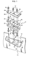
- the upper slewing body 2 is provided with an upper frame 7 as a base portion on which the working attachment 6 is attached, a cabin 8 loaded on the upper frame 7, a guard member 9 such as a guard panel, an engine 14, a hydraulic pump 15, a control valve 16, a plurality of delivery hoses (hereinafter, simply called as hoses) 17, a floor plate 29 (see FIG. 5 ), and a clamp body 31 (see FIG. 1 ).
- the upper frame 7 is a metal member, and is provided with left and right vertical plates 11, 12 extending longitudinally substantially over the entire length of the upper frame 7 in front and back directions, and a partition plate 13 extending laterally in left and right directions orthogonal to the vertical plates 11, 12 at a longitudinally intermediate portion of the upper frame 7.
- the space above the upper frame 7 is divided into a front section S 1 and a rear section S2 by the partition plate 13.
- An engine room 10 is formed in the rear section S2.
- the engine 14 is disposed in the rear section S2 (namely in the engine room 10), with the length direction thereof being aligned with the lateral direction (left and right directions) of the hydraulic shovel.
- the hydraulic pump 15 to be driven by the engine 14 is disposed on one of left and right sides of the engine 14 (normally, on the left side as shown in FIG. 8 , hereinafter, description is made based on this example).
- the cabin 8 is loaded on the left side of the front section S1, and the control valve 16 is disposed on the right side of the front section S1.
- the hoses 17 are adapted to connect between the hydraulic pump 15 and the control valve 16.
- the hoses 17 are connected between the hydraulic pump 15 and the control valve 16 through a cutaway 18 (see FIG. 1 ) formed in the partition plate 13. Intermediate portions of the hoses 17 are held by the clamp body 31 to be described later.
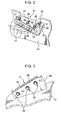
- the hydraulic shovel in the embodiment is provided with a metal clamp receiver 30 (a part of the upper frame 7) which bulges forwardly from a front surface of the partition plate 13, and with the clamp body 31 which is supported on the clamp receiver 30.
- the clamp receiver 30 is a metal plate with left and right ends thereof being bent upwardly. Further, the clamp receiver 30 has a placement surface 30a which is formed between the left and right bent portions, and which is adapted to place the clamp body 31 thereon.
- the placement surface 30a is a surface orthogonal to a slewing axis about which the upper slewing body 2 is slewed.
- the clamp receiver 30 has two attachment pins 42, 42 projecting upwardly from the placement surface 30a. These attachment pins 42 are insertable into the clamp body 31 so that the clamp body 31 to be described later is attached onto the clamp receiver 30 in a state that the clamp body 31 is vertically movable.
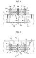
- the method for fixing the attachment pin 42 onto the clamp receiver 30 is not specifically limited. Specifically, as shown in FIG. 4 , a lower end of the attachment pin 42 may be fixedly attached to the clamp receiver 30 by e.g. welding in a state that the attachment pin 42 passes through the clamp receiver 30. Further alternatively, a lower end of the attachment pin 42 may be fixedly attached to the placement surface 30a of the clamp receive 30.
- the clamp body 31 is formed on the front surface side of the partition plate 13, while facing the cutaway 18. Specifically, the clamp body 31 is disposed horizontally in a state that the clamp body 31 is placed on the placement surface 30a of the clamp receiver 30.
- the clamp body 31 holds intermediate portions of the respective hoses 17.
- the clamp body 31 is provided with a pair of upper and lower clamping members 32, 33 for fixing the respective hoses 17 while holding the respective hoses 17 from both sides thereof in the diameter direction thereof, and a coupling mechanism for coupling the clamping members 32 and 33 to each other in a state that the respective hoses 17 are sandwiched therebetween.
- the clamping members 32, 33 are made of an elastic material such as rubber. Further, each of the clamping members 32, 33 is formed with two clamping member pin holes 40 for passing the corresponding attachment pins 42 therethrough.
- the clamping member pin holes 40 are respectively formed in a transversely center portion (a center portion in left and right directions) and in a left portion of each of the clamping members 32, 33 at positions corresponding to the attachment pins 42.
- the clamping member pin holes 40 in the clamping member 32, and the clamping member pin holes 40 in the clamping member 33 are formed at such a position that the clamping member pin holes 40 in the clamping member 32, and the clamping member pin holes 40 in the clamping member 33 align with each other in a state that the clamping members 32, 33 are placed one over the other.
- recess grooves 32a, 33a for receiving the hoses 17 are respectively formed in the clamping members 32, 33 at positions opposite to each other in a state that the clamping member pin holes 40 in the clamping member 32, and the clamping member pin holes 40 in the clamping member 33 align each other.
- the recess grooves 32a, 33a each has an inner lateral surface which is configured to firmly contact with an outer lateral surface of the corresponding hose 17.
- the coupling mechanism is provided with a metal clamp presser 34 which is placed over the top surface of the upper clamping member 32, a plurality of tubular metal spacers 35 which pass through both of the clamping members 32 and 33, fastening bolts 36 which pass through the corresponding metal spacers 35 from below, nuts 37 which are screwed into upper ends of the corresponding fastening bolts 36, metal washers 38 which are disposed between heads of the corresponding fastening bolts 36 and the lower clamping member 33, and metal washers 39 which are disposed between the corresponding nuts 37 and the clamp presser 34.
- the clamp presser 34 is a metal plate for holding the clamping members 32, 33.
- the clamp presser 34 is formed with three insertion holes 34a for passing lead ends (screw portions) of the fastening bolts 36 therethrough, and each of which has a size incapable of passing the metal spacer 35.
- the clamp presser 34 is formed with two clamp presser pin holes 41 at positions corresponding to the clamping member pin holes 40 formed in the clamping members 32, 33.
- the metal spacer 35 is adapted to keep the thickness of the pair of clamping members 32, 33 to a predetermined size or more against a fastening force by the fastening bolt 36 and the nut 37. Specifically, the metal spacer 35 keeps the thickness of the pair of clamping members 32, 33 by restricting the washers 38, 39 from coming close to each other at both ends thereof.
- the fastening bolt 36 and the nut 37 press the pair of clamping members 32, 33 toward the clamp presser 34.
- the pair of clamping members 32, 33 are held between the washers 38, 39 by engagement of the lead ends of the fastening bolts 36 with the nuts 37.
- the three members i.e. the pair of clamping members 32, 33 and the clamp presser 34 are integrally united to each other.
- the diameter of the clamping member pin hole 40 is set larger than the diameter of the attachment pin 42, and is set smaller than the diameter of the clamp presser pin hole 41.
- a is the diameter of the attachment pin 42
- b is the diameter of the clamping member pin hole 40 of the clamping members 32, 33
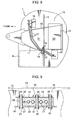
- c is the diameter of the clamp presser pin hole 41 of the clamp presser 34 (see FIG. 6 ).
- the clamping member pin hole 40 and the clamp presser pin hole 41 are formed into a clearance hole having a larger diameter than the diameter of the attachment pin 42, and the clamp presser pin hole 41 is formed into a hole having a larger diameter than the diameter of the clamping member pin hole 40.
- the clamp receiver 30 in this embodiment is formed with three relief holes 43 in a region between the left and right bent portions of the clamp receiver 30.
- the three relief holes 43 vertically pass through the clamp receiver 30.
- These relief holes 43 are adapted to avoid contact between the heads of the fastening bolts 36 and the washers 38, and the clamp receiver 30.
- each of the relief holes 43 is formed in the clamp receiver 30 at a position corresponding to the corresponding fastening bolt 36.
- each of the relief holes 43 has a larger diameter than the diameter of the head of the fastening bolt 36 and the diameter of the lower washer 38 to avoid contact between the clamp receiver 30, and the head of the fastening bolt 36 and the washer 38.
- the clamp body 31 is attached onto the clamp receiver 30 as follows. Firstly, as shown in FIG. 4 , the respective hoses 17 are sandwiched between the clamping members 32 and 33, and the clamp presser 34 is placed on the clamping members 32, 33. In this state, the three members i.e. the clamping members 32, 33 and the clamp presser 34 are fastened to each other by the fastening bolts 36 and the nuts 37. The clamp body 31 is assembled in this way.
- the clamp body 31 is placed on the placement surface 30a of the clamp receiver 30 while allowing the attachment pins 42, 42 to pass through the clamping member pin holes 40 and through the clamp presser pin holes 41.
- the clamp body 31 is attached onto the clamp receiver 30 in a state that the clamp body 31 is vertically movable in the length direction (up and down directions) of the attachment pins 42, 42.
- inserting the attachment pins 42 in the clamping member pin holes 40 enables to attach the clamp body 31 onto the clamp receiver 30 in a state that the clamp body 31 is movable in the length direction of the attachment pin 42.
- the clamp body 31 is attached onto the upper frame 7 in a state that vibrations from the clamp receiver 30 are cut off, unlike the clamp arrangement shown in FIG. 9 , in which the clamp body and the frame are fixed in all directions as one unit.
- the embodiment is particularly advantageous in reducing noises in a cabin resulting from vibrations, and in improving operability and comfort in working in a construction machine constructed such that the cabin 8 is loaded on the upper frame 7 like a hydraulic shovel.
- the clamp body 31 is securely held onto the clamp receiver 30 by insertion of the attachment pins 42 through the clamping member pin holes 40 and through the clamp receiver pin holes 41.
- the clamp body 31 can sufficiently function as means for holding the respective hoses 17 at a predetermined position.
- the clamping members 32, 33 are made of an elastic material; and the clamp body 31 is provided with the fastening bolts 36 and the nuts 37 for pressing the clamping members 32, 33 toward the clamp presser 34, and with the metal spacers 35 for keeping the thickness of the clamping members 32, 33.
- vibrations of the hoses 17 can be absorbed by elastic deformation of the clamping members 32, 33, and the vibration absorbing function can be effectively secured by suppressing excessive pressing of the clamping members 32, 33 by the metal spacers 35.
- the clamp body 31 is placed on the placement surface 30a in such a manner that the clamp presser 34 faces upward, and the contact between the heads of the fastening bolts 36 and the washers 38, and the clamp receiver 30 is avoided by the formation of the relief holes 43.
- the contact between the members made of a metal i.e. the clamp receiver 30, the clamp presser 34, the fastening bolts 36, and the nuts 37) is avoided to thereby effectively suppress transmission of vibrations via these metal members.
- each of the relief holes 43 has such a size as to avoid the contact between the washer 38 and the clamp receiver 30.
- the diameter "b" of the clamping member pin hole 40 is set larger than the diameter "a" of the attachment pin 42 and is set smaller than the diameter "c" of the clamp presser pin hole 41.
- the contact between the heads of the fastening bolts 36 and the washers 38, and the clamp receiver 30 is avoided by the formation of the relief holes 43 as described above.
- the floor plate 29 is disposed above the clamp body 31.
- the existence of the floor plate 29 prevents disengagement of the clamp body 31 from the attachment pins 42.
- the above arrangement enables to keep the inserted state of the attachment pins 42 in the clamp body 31, even if the clamp body 31 is vertically vibrated by hydraulic pulsation of the hoses 17.
- the clamp body 31 is attached in such a manner that the clamping members 32, 33 are vertically disposed one above the other.
- the clamp body 31 may be attached in such a manner that the clamping members 32, 33 are disposed side by side.
- the arrangement substantially the same as in the embodiment may be applied. It is, however, desirable to provide a stopper for preventing horizontal disengagement of the clamp body 31 from the attachment pins 42, at the lead end side of the attachment pins 42.
- An aspect of the invention is directed to a construction machine including a frame, with an attachment pin projecting therefrom; and a clamp body attached to the frame.
- the clamp body includes a pair of clamping members which sandwich a pipe from both sides of the pipe in a diameter direction thereof; and a coupling mechanism which is operable to couple the pair of clamping members to each other in a state that the pipe is sandwiched between the pair of clamping members.
- Each of the pair of clamping members is formed with a clamping member pin hole for passing the attachment pin therethrough, and the attachment pin passes through both of the pair of clamping members via the clamping member pin holes, whereby the clamp body is attached onto the frame in a state that the clamp body is movable in a length direction of the attachment pin.
- the clamp body it is possible to attach the clamp body onto the frame in a state that the clamp body is movable in the length direction of the attachment pin by passing the attachment pin through the clamping member pin holes.
- the above arrangement is particularly advantageous in reducing noises in a cabin, and in improving operability and comfort in working in a construction machine constructed such that a cabin is loaded on an upper frame like a hydraulic shovel.
- the pair of clamping members may be made of an elastic material
- the coupling mechanism may include a metal clamp presser which is placed on one of the pair of clamping members, with the one of the pair of clamping members being interposed between the clamp presser and the other of the pair of clamping members, a pressing mechanism which presses the other of the pair of clamping members toward the clamp presser, and a spacer which keeps a thickness of the pair of clamping members to a predetermined size or more against a pressing force by the pressing mechanism
- the clamp presser may be formed with a clamp presser pin hole for passing the attachment pin therethrough, at a position corresponding to the clamping member pin hole.
- the pair of clamping members are made of an elastic material
- the coupling mechanism includes the pressing mechanism which presses the pair of clamping members toward the clamp presser, and the spacer which keeps the thickness of the pair of clamping members against a pressing force by the pressing mechanism.
- the spacer may be a tubular member which passes through both of the pair of clamping members
- the pressing mechanism may include a fastening bolt which passes through the spacer and through the clamp presser, and a nut which is screwed into a lead end of the fastening bolt.
- the frame may have a placement surface on which the clamp body is placed, the attachment pin may project upwardly from the placement surface, the clamp body may be placed on the placement surface, with the clamp presser being directed upwardly, and the frame may be formed with a contact avoiding portion which avoids contact between the frame, and one of a head of the fastening bolt and the nut which is disposed below the frame.
- the clamp body is placed on the placement surface, with the clamp presser being directed upwardly, and the contact avoiding portion avoids the contact between the frame, and one of the head of the fastening bolt and the nut which is disposed below the frame.
- the contact between the members made of a metal i.e. the frame, the clamp presser, the bolt, and the nut
- the coupling mechanism may include a first washer which is disposed between the head of the fastening bolt and the pair of clamping members, and a second washer which is disposed between the nut and the pair of clamping members, and the contact avoiding portion may have such a size as to avoid the contact between the frame, and one of the first washer and the second washer which is disposed below the frame.
- the first washer is disposed between the fastening bolt and the pair of clamping members
- the second washer is disposed between the nut and the pair of clamping members
- the contact avoiding portion has such a size as to avoid the contact between the frame and the first washer, and between the frame and the second washer.
- the diameter of the clamping member pin hole may be set larger than the diameter of the attachment pin, and may be set smaller than the diameter of the clamp presser pin hole.
- the diameter of the clamping member pin hole is set larger than the diameter of the attachment pin, and is set smaller than the diameter of the clamp presser pin hole.
- the construction machine may further include a lower propelling body, and the frame may be an upper frame which is loaded slewably onto the lower propelling body.
- the upper frame may include a partition plate which divides a space above the upper frame into a front section and a rear section, and a clamp receiver which bulges from the partition plate, with the attachment pin projecting upwardly, and the clamp body may be supported on the clamp receiver in a state that the attachment pin is received through the clamp body.
- the attachment pin projects upwardly on the clamp receiver of the upper frame.
- the clamp body is placed on the clamp receiver, with the attachment pin passing through the clamp body. This enables to attach the clamp body onto the frame, while suppressing transmission of vibrations to the upper frame via the partition plate.
- the construction machine may further include a stopper member which prevents disengagement of the clamp body from the attachment pin.
- the construction machine is provided with the stopper member which prevents disengagement of the clamp body from the attachment pin. This enables to securely attach the clamp body onto the frame, while suppressing transmission of vibrations from the pipe to the frame as described above.
- a construction machine is provided with a clamp receiver 30 with a projecting attachment pin 42, and a clamp body 31 attached onto the clamp receiver 30.
- the clamp body 31 includes a pair of clamping members 32, 33 which sandwich a hose 17 from both sides of the hose 17 in the diameter direction thereof, and a coupling mechanism which is operable to couple the clamping members 32, 33 to each other in a state that the hose 17 is sandwiched between the clamping members 32 and 33.
- Each of the clamping members 32, 33 is formed with a clamping member pin hole 40 for passing the attachment pin 42 therethrough.
Landscapes
- Engineering & Computer Science (AREA)
- Mining & Mineral Resources (AREA)
- Civil Engineering (AREA)
- General Engineering & Computer Science (AREA)
- Structural Engineering (AREA)
- Component Parts Of Construction Machinery (AREA)
- Supports For Pipes And Cables (AREA)
Applications Claiming Priority (1)
| Application Number | Priority Date | Filing Date | Title |
|---|---|---|---|
| JP2010235770A JP5177201B2 (ja) | 2010-10-20 | 2010-10-20 | 建設機械の配管クランプ |
Publications (2)
| Publication Number | Publication Date |
|---|---|
| EP2444554A2 true EP2444554A2 (de) | 2012-04-25 |
| EP2444554A3 EP2444554A3 (de) | 2013-03-20 |
Family
ID=44993484
Family Applications (1)
| Application Number | Title | Priority Date | Filing Date |
|---|---|---|---|
| EP11185775A Withdrawn EP2444554A3 (de) | 2010-10-20 | 2011-10-19 | Schlauchschelle für Baumaschine |
Country Status (4)
| Country | Link |
|---|---|
| US (1) | US20120097468A1 (de) |
| EP (1) | EP2444554A3 (de) |
| JP (1) | JP5177201B2 (de) |
| CN (1) | CN202509553U (de) |
Families Citing this family (15)
| Publication number | Priority date | Publication date | Assignee | Title |
|---|---|---|---|---|
| JP5403013B2 (ja) * | 2011-08-24 | 2014-01-29 | コベルコ建機株式会社 | 作業機械における配管取付け構造 |
| CN103958786A (zh) * | 2011-11-30 | 2014-07-30 | 沃尔沃建造设备有限公司 | 用于动臂回转式挖掘机的液压管路固定装置 |
| JP2014105499A (ja) * | 2012-11-28 | 2014-06-09 | Kobelco Contstruction Machinery Ltd | 建設機械のアッパーフレーム |
| BR112015029531A2 (pt) * | 2013-05-30 | 2017-07-25 | Volvo Constr Equip Ab | dispositivo de fixação de canos para máquinas de construção |
| JP6345087B2 (ja) * | 2014-11-14 | 2018-06-20 | Kyb−Ys株式会社 | 機器取付構造 |
| JP6588206B2 (ja) * | 2014-12-22 | 2019-10-09 | Nok株式会社 | 配管固定部材 |
| JP6640515B2 (ja) * | 2015-09-30 | 2020-02-05 | 株式会社クボタ | 作業機 |
| CN105333231A (zh) * | 2015-12-04 | 2016-02-17 | 四川海搏液压机械有限公司 | 一种液压管夹持工装 |
| US9925983B2 (en) * | 2016-07-18 | 2018-03-27 | Caterpillar Inc. | System and method to eliminate or reduce frame contact during operation of articulated machine |
| US10995477B2 (en) * | 2017-03-01 | 2021-05-04 | William Lewis | Coupler guard system |
| JP6873771B2 (ja) * | 2017-03-22 | 2021-05-19 | 三菱ロジスネクスト株式会社 | 荷役車両 |
| CN110224350B (zh) * | 2018-03-02 | 2021-08-10 | 神讯电脑(昆山)有限公司 | 电缆夹 |
| JP6832305B2 (ja) * | 2018-03-15 | 2021-02-24 | 日立建機株式会社 | 建設機械 |
| KR102764812B1 (ko) * | 2018-10-02 | 2025-02-06 | 두산 밥캣 노스 아메리카, 인크. | 분배 유압 시스템 |
| EP4365370A4 (de) * | 2021-06-29 | 2025-06-11 | Kubota Corporation | Schlauchklemmenstruktur und arbeitsmaschine |
Citations (2)
| Publication number | Priority date | Publication date | Assignee | Title |
|---|---|---|---|---|
| JP2001317081A (ja) | 2000-05-10 | 2001-11-16 | Hitachi Constr Mach Co Ltd | 旋回式建設機械 |
| JP2010235770A (ja) | 2009-03-31 | 2010-10-21 | Yamatou Co Ltd | 皮革材の表面処理方法 |
Family Cites Families (56)
| Publication number | Priority date | Publication date | Assignee | Title |
|---|---|---|---|---|
| USRE26011E (en) * | 1966-05-03 | Tube clamps | ||
| US2160689A (en) * | 1938-03-31 | 1939-05-30 | Vapor Car Heating Co Inc | Support for radiating pipes |
| US2248170A (en) * | 1938-08-09 | 1941-07-08 | Robert G Hansen | Adjustable carrying bracket for automobiles |
| US2361943A (en) * | 1942-01-23 | 1944-11-07 | Adel Prec Products Corp | Conduit supporting and bonding block |
| US2362124A (en) * | 1942-08-18 | 1944-11-07 | Adel Prec Products Corp | Conduit support |
| US2425935A (en) * | 1943-07-10 | 1947-08-19 | Hayman Richard Lowell | Tube holding block |
| US2404531A (en) * | 1943-12-13 | 1946-07-23 | Adel Prec Products Corp | Conduit supporting block |
| US2354919A (en) * | 1944-04-08 | 1944-08-01 | Leroy Robert Bowles | Multiple clamping device |
| US2807398A (en) * | 1952-12-03 | 1957-09-24 | Mack G Mathews | Fish pole carrier |
| US3047263A (en) * | 1960-01-18 | 1962-07-31 | Charles F Mittenzwei | Bracket |
| US3099056A (en) * | 1960-11-07 | 1963-07-30 | Rolls Royce | Clamp |
| US3186051A (en) * | 1964-01-02 | 1965-06-01 | Jessie A Waddell | Tube clamp |
| US3216683A (en) * | 1964-03-10 | 1965-11-09 | Donald A Girard | Tube clamps for multiple tube layers |
| US3261579A (en) * | 1964-09-21 | 1966-07-19 | Engman Mfg Company | Universal muffler and tail pipe holding bracket |
| US3397431A (en) * | 1967-05-12 | 1968-08-20 | Hydro Craft Inc | Tube clamp assembly |
| US3531071A (en) * | 1968-08-16 | 1970-09-29 | Arthur F Kubli | Cable support |
| US3582029A (en) * | 1969-04-09 | 1971-06-01 | Ramcor Inc | Clamp apparatus |
| US3682422A (en) * | 1970-10-05 | 1972-08-08 | Theodore D Evans | Tube clamping member |
| US4431152A (en) * | 1981-12-10 | 1984-02-14 | Square D Company | Adjustable cable restraint assembly |
| US4444370A (en) * | 1982-06-14 | 1984-04-24 | Guenther Krueger | Pipe support device |
| US5098047A (en) * | 1990-10-18 | 1992-03-24 | Flex Rail, Inc. | Tube clamp |
| JPH0510547U (ja) * | 1991-07-18 | 1993-02-12 | 油谷重工株式会社 | パイプクランプ装置 |
| US5205520A (en) * | 1992-05-26 | 1993-04-27 | Hydro-Craft, Inc. | Retaining block for clamping system |
| JPH0596670U (ja) * | 1992-06-01 | 1993-12-27 | 日立建機株式会社 | ホース固定部材 |
| JP2834383B2 (ja) * | 1993-04-09 | 1998-12-09 | 株式会社クボタ | バックホウの旋回台構造 |
| JPH09210251A (ja) * | 1996-01-30 | 1997-08-12 | Hitachi Constr Mach Co Ltd | 建設機械のフロント配管保持装置 |
| US6009643A (en) * | 1996-05-14 | 2000-01-04 | Kabushiki Kaisha Kobe Seiko Sho | Hydraulic working machine |
| JPH1113940A (ja) * | 1997-06-30 | 1999-01-22 | Hitachi Constr Mach Co Ltd | 流体用配管の支持装置 |
| US5971663A (en) * | 1997-07-10 | 1999-10-26 | Brothers; Jerry T. | Culvert collar |
| US5996945A (en) * | 1997-10-31 | 1999-12-07 | Caterpillar Inc. | Hose clamp assembly offset mounting capability |
| JP3755788B2 (ja) * | 1998-04-08 | 2006-03-15 | 小松フォークリフト株式会社 | 油圧配管装置 |
| JP3967501B2 (ja) * | 1999-09-22 | 2007-08-29 | 日立建機株式会社 | 旋回式建設機械 |
| JP4678705B2 (ja) * | 2000-11-29 | 2011-04-27 | 株式会社小松製作所 | 油圧駆動式作業機 |
| JP2003278178A (ja) * | 2002-03-25 | 2003-10-02 | Komatsu Ltd | 作業機用の油圧配管支持構造 |
| JP3979528B2 (ja) * | 2002-09-24 | 2007-09-19 | 新キャタピラー三菱株式会社 | 建設機械におけるホース支持構造 |
| JP2004217195A (ja) * | 2002-12-26 | 2004-08-05 | Yamaha Motor Co Ltd | 雪上車の懸架装置 |
| JP2004218659A (ja) * | 2003-01-09 | 2004-08-05 | Kobelco Contstruction Machinery Ltd | クランプ |
| JP4082587B2 (ja) * | 2003-02-20 | 2008-04-30 | 新キャタピラー三菱株式会社 | 建設機械における配管構造 |
| JP2004285702A (ja) * | 2003-03-24 | 2004-10-14 | Komatsu Ltd | スイング式油圧ショベルの配管取り回し構造 |
| JP3956907B2 (ja) * | 2003-06-24 | 2007-08-08 | コベルコ建機株式会社 | 小型ショベル |
| US20050247505A1 (en) * | 2004-05-06 | 2005-11-10 | Nagle Christopher N | Frame and bracket system for motorized vehicle |
| JP4631338B2 (ja) * | 2004-07-23 | 2011-02-16 | トヨタ自動車株式会社 | クランプ |
| JP4217687B2 (ja) * | 2005-03-14 | 2009-02-04 | ヤンマー株式会社 | ローダの配管構造 |
| JP4543996B2 (ja) * | 2005-03-29 | 2010-09-15 | コベルコ建機株式会社 | 作業機械 |
| JP4720499B2 (ja) * | 2005-12-28 | 2011-07-13 | コベルコ建機株式会社 | 作業機械 |
| JP4894466B2 (ja) * | 2006-11-07 | 2012-03-14 | コベルコ建機株式会社 | 建設機械のホースクランプ装置 |
| JP4941089B2 (ja) * | 2007-05-15 | 2012-05-30 | コベルコ建機株式会社 | 上部旋回体及びこれを備えた建設機械 |
| JP2009243212A (ja) * | 2008-03-31 | 2009-10-22 | Sumitomo (Shi) Construction Machinery Co Ltd | 建設機械の油圧配管用クランプ装置 |
| JP4954159B2 (ja) * | 2008-08-05 | 2012-06-13 | 日立建機株式会社 | ホースクランプ装置 |
| JP4585585B2 (ja) * | 2008-08-06 | 2010-11-24 | 本田技研工業株式会社 | 車体構造 |
| US8074945B2 (en) * | 2008-12-15 | 2011-12-13 | Caterpillar Inc. | Conduit mounting system |
| JP5003711B2 (ja) * | 2009-04-02 | 2012-08-15 | コベルコクレーン株式会社 | 配管用クランプ装置 |
| JP5453887B2 (ja) * | 2009-04-03 | 2014-03-26 | コベルコ建機株式会社 | ホースクランプ |
| JP5141678B2 (ja) * | 2009-12-24 | 2013-02-13 | コベルコ建機株式会社 | 配管クランプ |
| JP5046138B2 (ja) * | 2009-12-26 | 2012-10-10 | コベルコ建機株式会社 | アタッチメントホースのクランプ構造 |
| US8443923B2 (en) * | 2011-03-17 | 2013-05-21 | Cnh America Llc | Vibration isolator device |
-
2010
- 2010-10-20 JP JP2010235770A patent/JP5177201B2/ja not_active Expired - Fee Related
-
2011
- 2011-10-11 US US13/270,458 patent/US20120097468A1/en not_active Abandoned
- 2011-10-19 EP EP11185775A patent/EP2444554A3/de not_active Withdrawn
- 2011-10-20 CN CN201120421239.8U patent/CN202509553U/zh not_active Expired - Fee Related
Patent Citations (2)
| Publication number | Priority date | Publication date | Assignee | Title |
|---|---|---|---|---|
| JP2001317081A (ja) | 2000-05-10 | 2001-11-16 | Hitachi Constr Mach Co Ltd | 旋回式建設機械 |
| JP2010235770A (ja) | 2009-03-31 | 2010-10-21 | Yamatou Co Ltd | 皮革材の表面処理方法 |
Also Published As
| Publication number | Publication date |
|---|---|
| JP5177201B2 (ja) | 2013-04-03 |
| JP2012087549A (ja) | 2012-05-10 |
| US20120097468A1 (en) | 2012-04-26 |
| CN202509553U (zh) | 2012-10-31 |
| EP2444554A3 (de) | 2013-03-20 |
Similar Documents
| Publication | Publication Date | Title |
|---|---|---|
| EP2444554A2 (de) | Schlauchschelle für Baumaschine | |
| CN100515689C (zh) | 安装破碎机用的托架 | |
| US8950538B2 (en) | Working machine | |
| US8128155B2 (en) | Construction machine | |
| US8376063B2 (en) | Structure for attaching rear work machine to tractor | |
| US6340201B1 (en) | Anti-vibration support for construction machine cab | |
| US9333992B2 (en) | Upper slewing body for use in construction machine | |
| US20170009425A1 (en) | Cab Protection Device for Working Machine | |
| JP6523426B2 (ja) | 取付金具、取付ユニット、及び鉄道車両 | |
| JP4296987B2 (ja) | エンジンマウント構造 | |
| EP2960380A1 (de) | Baumaschine | |
| EP2078638A2 (de) | Baumaschine mit Vorrichtungen zur Befestigung von Seitenspiegeln | |
| US8899260B2 (en) | Construction machine | |
| JP5516439B2 (ja) | 建設機械 | |
| US20070278811A1 (en) | System for operably coupling a vehicle cab to a vehicle | |
| EP3798369A1 (de) | Baumaschine | |
| JP4954159B2 (ja) | ホースクランプ装置 | |
| JP3979528B2 (ja) | 建設機械におけるホース支持構造 | |
| JP2013241817A (ja) | 建設機械 | |
| JP6473663B2 (ja) | 防振装置 | |
| JP4418328B2 (ja) | 旋回フレーム構造 | |
| JP5164177B2 (ja) | キャブを備えた建設機械 | |
| JP5305403B2 (ja) | 建設機械におけるバッテリの位置決め構造 | |
| CN210859423U (zh) | 一种钢材安装稳定加固装置 | |
| JP4835988B2 (ja) | マウントブラケット |
Legal Events
| Date | Code | Title | Description |
|---|---|---|---|
| AK | Designated contracting states |
Kind code of ref document: A2 Designated state(s): AL AT BE BG CH CY CZ DE DK EE ES FI FR GB GR HR HU IE IS IT LI LT LU LV MC MK MT NL NO PL PT RO RS SE SI SK SM TR |
|
| AX | Request for extension of the european patent |
Extension state: BA ME |
|
| PUAI | Public reference made under article 153(3) epc to a published international application that has entered the european phase |
Free format text: ORIGINAL CODE: 0009012 |
|
| PUAL | Search report despatched |
Free format text: ORIGINAL CODE: 0009013 |
|
| AK | Designated contracting states |
Kind code of ref document: A3 Designated state(s): AL AT BE BG CH CY CZ DE DK EE ES FI FR GB GR HR HU IE IS IT LI LT LU LV MC MK MT NL NO PL PT RO RS SE SI SK SM TR |
|
| AX | Request for extension of the european patent |
Extension state: BA ME |
|
| RIC1 | Information provided on ipc code assigned before grant |
Ipc: E02F 9/22 20060101AFI20130213BHEP |
|
| STAA | Information on the status of an ep patent application or granted ep patent |
Free format text: STATUS: THE APPLICATION IS DEEMED TO BE WITHDRAWN |
|
| 18D | Application deemed to be withdrawn |
Effective date: 20130921 |