EP2431536B1 - Machine de construction - Google Patents
Machine de construction Download PDFInfo
- Publication number
- EP2431536B1 EP2431536B1 EP11181497.6A EP11181497A EP2431536B1 EP 2431536 B1 EP2431536 B1 EP 2431536B1 EP 11181497 A EP11181497 A EP 11181497A EP 2431536 B1 EP2431536 B1 EP 2431536B1
- Authority
- EP
- European Patent Office
- Prior art keywords
- surface plate
- plate
- urea water
- water tank
- tank
- Prior art date
- Legal status (The legal status is an assumption and is not a legal conclusion. Google has not performed a legal analysis and makes no representation as to the accuracy of the status listed.)
- Active
Links
Images


Classifications
-
- E—FIXED CONSTRUCTIONS
- E02—HYDRAULIC ENGINEERING; FOUNDATIONS; SOIL SHIFTING
- E02F—DREDGING; SOIL-SHIFTING
- E02F9/00—Component parts of dredgers or soil-shifting machines, not restricted to one of the kinds covered by groups E02F3/00 - E02F7/00
- E02F9/08—Superstructures; Supports for superstructures
- E02F9/0833—Improving access, e.g. for maintenance, steps for improving driver's access, handrails
-
- B—PERFORMING OPERATIONS; TRANSPORTING
- B01—PHYSICAL OR CHEMICAL PROCESSES OR APPARATUS IN GENERAL
- B01D—SEPARATION
- B01D53/00—Separation of gases or vapours; Recovering vapours of volatile solvents from gases; Chemical or biological purification of waste gases, e.g. engine exhaust gases, smoke, fumes, flue gases, aerosols
- B01D53/34—Chemical or biological purification of waste gases
- B01D53/92—Chemical or biological purification of waste gases of engine exhaust gases
- B01D53/94—Chemical or biological purification of waste gases of engine exhaust gases by catalytic processes
-
- B—PERFORMING OPERATIONS; TRANSPORTING
- B60—VEHICLES IN GENERAL
- B60K—ARRANGEMENT OR MOUNTING OF PROPULSION UNITS OR OF TRANSMISSIONS IN VEHICLES; ARRANGEMENT OR MOUNTING OF PLURAL DIVERSE PRIME-MOVERS IN VEHICLES; AUXILIARY DRIVES FOR VEHICLES; INSTRUMENTATION OR DASHBOARDS FOR VEHICLES; ARRANGEMENTS IN CONNECTION WITH COOLING, AIR INTAKE, GAS EXHAUST OR FUEL SUPPLY OF PROPULSION UNITS IN VEHICLES
- B60K13/00—Arrangement in connection with combustion air intake or gas exhaust of propulsion units
- B60K13/04—Arrangement in connection with combustion air intake or gas exhaust of propulsion units concerning exhaust
-
- E—FIXED CONSTRUCTIONS
- E02—HYDRAULIC ENGINEERING; FOUNDATIONS; SOIL SHIFTING
- E02F—DREDGING; SOIL-SHIFTING
- E02F9/00—Component parts of dredgers or soil-shifting machines, not restricted to one of the kinds covered by groups E02F3/00 - E02F7/00
- E02F9/08—Superstructures; Supports for superstructures
- E02F9/0858—Arrangement of component parts installed on superstructures not otherwise provided for, e.g. electric components, fenders, air-conditioning units
- E02F9/0883—Tanks, e.g. oil tank, urea tank, fuel tank
-
- F—MECHANICAL ENGINEERING; LIGHTING; HEATING; WEAPONS; BLASTING
- F01—MACHINES OR ENGINES IN GENERAL; ENGINE PLANTS IN GENERAL; STEAM ENGINES
- F01N—GAS-FLOW SILENCERS OR EXHAUST APPARATUS FOR MACHINES OR ENGINES IN GENERAL; GAS-FLOW SILENCERS OR EXHAUST APPARATUS FOR INTERNAL COMBUSTION ENGINES
- F01N3/00—Exhaust or silencing apparatus having means for purifying, rendering innocuous, or otherwise treating exhaust
- F01N3/08—Exhaust or silencing apparatus having means for purifying, rendering innocuous, or otherwise treating exhaust for rendering innocuous
- F01N3/10—Exhaust or silencing apparatus having means for purifying, rendering innocuous, or otherwise treating exhaust for rendering innocuous by thermal or catalytic conversion of noxious components of exhaust
- F01N3/18—Exhaust or silencing apparatus having means for purifying, rendering innocuous, or otherwise treating exhaust for rendering innocuous by thermal or catalytic conversion of noxious components of exhaust characterised by methods of operation; Control
- F01N3/20—Exhaust or silencing apparatus having means for purifying, rendering innocuous, or otherwise treating exhaust for rendering innocuous by thermal or catalytic conversion of noxious components of exhaust characterised by methods of operation; Control specially adapted for catalytic conversion ; Methods of operation or control of catalytic converters
- F01N3/2066—Selective catalytic reduction [SCR]
- F01N3/208—Control of selective catalytic reduction [SCR], e.g. dosing of reducing agent
-
- F—MECHANICAL ENGINEERING; LIGHTING; HEATING; WEAPONS; BLASTING
- F01—MACHINES OR ENGINES IN GENERAL; ENGINE PLANTS IN GENERAL; STEAM ENGINES
- F01N—GAS-FLOW SILENCERS OR EXHAUST APPARATUS FOR MACHINES OR ENGINES IN GENERAL; GAS-FLOW SILENCERS OR EXHAUST APPARATUS FOR INTERNAL COMBUSTION ENGINES
- F01N3/00—Exhaust or silencing apparatus having means for purifying, rendering innocuous, or otherwise treating exhaust
- F01N3/08—Exhaust or silencing apparatus having means for purifying, rendering innocuous, or otherwise treating exhaust for rendering innocuous
- F01N3/10—Exhaust or silencing apparatus having means for purifying, rendering innocuous, or otherwise treating exhaust for rendering innocuous by thermal or catalytic conversion of noxious components of exhaust
- F01N3/24—Exhaust or silencing apparatus having means for purifying, rendering innocuous, or otherwise treating exhaust for rendering innocuous by thermal or catalytic conversion of noxious components of exhaust characterised by constructional aspects of converting apparatus
- F01N3/28—Construction of catalytic reactors
-
- B—PERFORMING OPERATIONS; TRANSPORTING
- B60—VEHICLES IN GENERAL
- B60W—CONJOINT CONTROL OF VEHICLE SUB-UNITS OF DIFFERENT TYPE OR DIFFERENT FUNCTION; CONTROL SYSTEMS SPECIALLY ADAPTED FOR HYBRID VEHICLES; ROAD VEHICLE DRIVE CONTROL SYSTEMS FOR PURPOSES NOT RELATED TO THE CONTROL OF A PARTICULAR SUB-UNIT
- B60W2300/00—Indexing codes relating to the type of vehicle
- B60W2300/17—Construction vehicles, e.g. graders, excavators
-
- B—PERFORMING OPERATIONS; TRANSPORTING
- B60—VEHICLES IN GENERAL
- B60Y—INDEXING SCHEME RELATING TO ASPECTS CROSS-CUTTING VEHICLE TECHNOLOGY
- B60Y2200/00—Type of vehicle
- B60Y2200/40—Special vehicles
- B60Y2200/41—Construction vehicles, e.g. graders, excavators
- B60Y2200/412—Excavators
-
- F—MECHANICAL ENGINEERING; LIGHTING; HEATING; WEAPONS; BLASTING
- F01—MACHINES OR ENGINES IN GENERAL; ENGINE PLANTS IN GENERAL; STEAM ENGINES
- F01N—GAS-FLOW SILENCERS OR EXHAUST APPARATUS FOR MACHINES OR ENGINES IN GENERAL; GAS-FLOW SILENCERS OR EXHAUST APPARATUS FOR INTERNAL COMBUSTION ENGINES
- F01N2570/00—Exhaust treating apparatus eliminating, absorbing or adsorbing specific elements or compounds
- F01N2570/14—Nitrogen oxides
-
- F—MECHANICAL ENGINEERING; LIGHTING; HEATING; WEAPONS; BLASTING
- F01—MACHINES OR ENGINES IN GENERAL; ENGINE PLANTS IN GENERAL; STEAM ENGINES
- F01N—GAS-FLOW SILENCERS OR EXHAUST APPARATUS FOR MACHINES OR ENGINES IN GENERAL; GAS-FLOW SILENCERS OR EXHAUST APPARATUS FOR INTERNAL COMBUSTION ENGINES
- F01N2610/00—Adding substances to exhaust gases
- F01N2610/02—Adding substances to exhaust gases the substance being ammonia or urea
-
- F—MECHANICAL ENGINEERING; LIGHTING; HEATING; WEAPONS; BLASTING
- F01—MACHINES OR ENGINES IN GENERAL; ENGINE PLANTS IN GENERAL; STEAM ENGINES
- F01N—GAS-FLOW SILENCERS OR EXHAUST APPARATUS FOR MACHINES OR ENGINES IN GENERAL; GAS-FLOW SILENCERS OR EXHAUST APPARATUS FOR INTERNAL COMBUSTION ENGINES
- F01N2610/00—Adding substances to exhaust gases
- F01N2610/14—Arrangements for the supply of substances, e.g. conduits
- F01N2610/1453—Sprayers or atomisers; Arrangement thereof in the exhaust apparatus
Definitions
- the present invention relates to a construction machine such as a hydraulic excavator mounting a NOx purifying device for removing nitrogen oxides in an exhaust gas and a urea water tank thereon.
- a hydraulic excavator as a representative example of a construction machine is constituted by an automotive lower traveling structure, an upper revolving structure swingably mounted on the lower traveling structure, and a working mechanism liftably mounted on the front side of the upper revolving structure.
- the upper revolving structure is provided with a revolving frame serving as a support structural member, an engine mounted at the rear side of the revolving frame, and a cab located at the left front side of the revolving frame to be positioned along the left side of the working mechanism, wherein an operator's seat in which an operator is seated and the like are provided in the cab.
- a fuel tank is provided in the revolving frame to be positioned in the right side of the working mechanism for reserving fuel supplied to the engine, and an article accommodating box is provided in front of the fuel tank for accommodating articles such as tools, a grease gun, and various consumables.
- a diesel engine is adopted as the engine in the hydraulic excavator, and the diesel engine is supposed to discharge a large amount of nitrogen oxides (hereinafter referred to as NOx) and the like. Therefore, a NOx purifying device for purifying NOx is as a post-treatment device of the exhaust gas in the diesel engine.
- the NOx purifying device for example, is constructed to accommodate a urea selective reduction catalyst for removing NOx in the exhaust gas in an accommodating tubular casing provided in the halfway of an exhaust pipe of the engine.
- the hydraulic excavator is provided with a urea water tank for reserving a urea solution as a reducing agent and a urea water injection valve for injecting the urea solution in the urea water tank toward the upstream side of the urea selective reduction catalyst, and the urea water tank is connected to the urea water injection valve by a connecting pipe.
- WO2009/131561A1 discloses an apparatus for separately containing different fluids.
- a peripheral wall of a first vessel is configured as a fuel tank and extends beyond an end wall to form a rim.
- a recess is formed between the rim and the end wall, and a second vessel for containing urea water is accommodated in the recess.
- the construction which the present invention adopts is characterized in that the oil reservoir tank is formed of an angular tubular or a cylindrical side surface plate forming an outer peripheral surface, a bottom surface plate closing a bottom surface of the side surface plate, and a top surface plate closing a top surface of the side surface plate and including a flange portion extending furthermore to an outside in relation to the side surface plate, a surplus space portion is formed in a side of the outer peripheral surface of the side surface plate to be projected in the upper and lower directions in a range of the flange portion of the top surface plate, and the urea water tank is arranged along the oil reservoir tank in such a manner as to enter into the surplus space portion.
- the surplus space portion can be formed in the side of the outer peripheral surface of the side surface plate of the oil reservoir tank to be projected in the upper and lower directions in a range of the flange portion of the top surface plate.
- the urea water tank can be arranged along the oil reservoir tank in such a manner as to enter into the surplus space portion.
- the urea water tank is constructed to enter into the surplus space portion by using the surplus space portion formed in the oil reservoir tank, a capacity of the urea water tank can be increased as compared to a case of accommodating the urea water tank in the article accommodating box.
- urea water tank is arranged along the oil reservoir tank, it is possible to have easy access to the urea water tank at the time of filling urea water therein, and operability at the time of supplying the urea water can be improved.
- the urea water tank having a large capacity can be arranged by using the surplus space portion at the front side of the oil reservoir tank and the space portion between the oil reservoir tank and the article accommodating box.
- the oil reservoir tank can be formed only by connecting the first plate to the second plate and can be formed as a hollow container by the two plates.
- the front flange portion may be formed in the top surface plate to extend furthermore to the front side in relation to the front surface plate by the dimension difference between the first plate and the second plate in the front and rear directions
- the urea water tank may be positioned in the outer peripheral side of the front surface plate of the oil reservoir tank to be arranged in such a manner as to enter into the front surplus space portion projected in the upper and lower directions in a range of the front flange portion of the top surface plate. Therefore, the urea water tank having a large capacity can be arranged without sacrificing the installation space of the circumferential members.
- the oil reservoir tank can be formed only by connecting the first plate to the second plate and can be as a hollow container by the two plates, and the effect similar to that of the above paragraph (3) can be obtained.
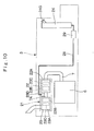
- Fig. 1 to Fig. 10 show a first embodiment in the present invention.
- the case is illustrated in which a urea water tank is arranged along an oil reservoir tank to be positioned inside of a front cover.
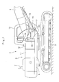
- a hydraulic excavator known as a representative example of a construction machine used in an excavating operation of earth and sand and the like.
- the hydraulic excavator 1 is largely constituted by an automotive crawler type lower traveling structure 2, an upper revolving structure 3 which is swingably mounted on the lower traveling structure 2 and constitutes a traveling vehicle together with the lower traveling structure 2, and a working mechanism 4 provided liftably on the front side of the upper revolving structure 3.
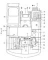
- the upper revolving structure 3 is constituted by a revolving frame 5, an engine 6, a cab 10, an operating oil tank 11, a fuel tank 12, an article accommodating box 16, a front cover 20, a post-treatment device 21, a urea water tank 24, and the like, which will be described hereinafter.
- the revolving frame 5 is the revolving frame as a support frame, which serves as a support structural member for the upper revolving structure 3.
- the revolving frame 5 is, constituted by a thick bottom plate 5A extending in the front and rear directions, left and right vertical plates 5B and 5C provided upright on the bottom plate 5A and extending in the front and rear directions to be spaced by a predetermined interval in the right and left directions, a plurality of extension beams 5D and 5E (see Fig.
- the extension beam 5D positioned at the front side serves to support a front side portion of the fuel tank 12 to be described later.
- the extension beam 5D has an upper flat portion formed to extend forward, and therefore, the urea water tank 24 can be mounted on the extension beam 5D.
- Indicated at 6 is the engine provided at the rear side of the revolving frame 5 (see Fig. 2 ), and the engine 6 is constructed as a diesel engine and mounted on the revolving frame 5 in a horizontal state.
- the engine 6 is provided with an exhaust pipe 7 for discharging an exhaust gas.
- the diesel engine 6 achieves a high efficiency and is advantageous in durability, and on the other hand, has a defect that harmful substances such as particulate matter (PM) and nitrogen oxides (NOx) are discharged together with the exhaust gas. Therefore, as described later, the post-treatment device 21, which will be described later, mounted in the exhaust pipe 7 is provided with a PM trapping device 22 for removing the particulate matter, and a NOx purifying device 23 for removing the nitrogen oxides (NOx).
- the PM trapping device 22 and the NOx purifying device 23 are connected by a connecting pipe portion 7A in the exhaust pipe 7.
- Indicated at 8 is a heat exchanger provided at the left side of the engine 6 (see Fig. 2 ), and the heat exchanger 8 is constituted by a radiator for cooling engine cooling water, an oil cooler for cooling operating oil, an intercooler for cooling air to be sucked for the engine 6, and the like.
- Indicated at 9 is a hydraulic pump mounted on the right side of the engine 6, and is driven by the engine 6 to discharge the operating oil from the operating oil tank 11 as pressurized oil.
- Indicated at 10 is the cab provided in the left front side of the revolving frame 5.
- An operator's seat in which an operator is seated, levers for operating various kinds of operations, a pedal and the like (any of them not shown) are located inside the cab 10.
- the operating oil tank 11 is the operating oil tank as an oil reservoir tank provided in the right side of the revolving frame 5 to be positioned forward of the engine 6.
- the operating oil tank 11 is formed as a pressure tight tank in a rectangular shape extending in the upper and lower directions.
- Designated at 12 is the fuel tank as an oil reservoir tank provided in the right side of the revolving frame 5 to be adjacent to the front side of the operating oil tank 11.
- the fuel tank 12 can reserve fuel enough for performing a predetermined working time operation.
- the fuel tank 12 is constituted by a first plate 13 and a second plate 14, which will be described later, and the like.
- the first plate 13 is the first plate constituting the fuel tank 12.
- a dimension L1 of the first plate 13 in the front and rear directions is set to be smaller than a dimension L2 of the second plate 14 in the front and rear directions to be described later (L1 ⁇ L2).
- the first plate 13 is formed by folding one sheet of a metallic plate carved out in a strip shape in a U-shape. That is, as shown in Fig.
- the first plate 13 is formed by a rectangular bottom surface plate 13A extending in the horizontal direction to be positioned in the bottom side, a front surface plate 13B extending to be bent upward from the front side of the bottom surface plate 13A, and a rear surface plate 13C extending in parallel with the front surface plate 13B to be bent upward from the rear side of the bottom surface plate 13A.
- Two screw holes 13D are provided in the front surface plate 13B in the intermediate position in the height direction to be spaced from each other in the right and left directions.
- Bolts 27 are screwed into the two screw holes 13D for mounting a fixing member 26 for fixing the urea water tank 24 to be described later.
- a third step plate 19 to be described later is mounted in the upper position of the front surface plate 13B.
- Denoted at 14 is the second plate provided to cover the first plate 13.
- a dimension L2 of the second plate 14 in the front and rear directions is set to be larger than a dimension L1 of the first plate 13 in the front and rear directions (L2 > L1).
- the second plate 14 is, in the substantially same way as the first plate 13, formed by folding one sheet of a metallic plate carved out in a strip shape in a reverse U-shape. That is, the second plate 14 is constructed of a rectangular top surface plate 14A extending in the horizontal direction to be positioned in the top side, a left surface plate 14B extending to be bent downward from the left side of the top surface plate 14A, and a right surface plate 14C to be bent downward from the right side of the top surface plate 14A.
- a fuel filling opening 14D for supplying fuel into the fuel tank 12 is provided in the top surface plate 14A of the second plate 14.
- the width dimension L2 of the second plate 14 in the front and rear directions is set to be larger than the dimension L1 between the front surface plate 13B and the rear surface plate 13C as the dimension of the first plate 13 in the front and rear directions (L2 > L1). Accordingly, as shown in Fig. 7 , the front surface plate 13B and the rear surface plate 13C of the first plate 13 are arranged to be shifted by 90 degrees in the circumferential direction between the left surface plate 14B and the right surface plate 14C of the second plate 14, and a peripheral edge of the first plate 13 is welded to the second plate 14 air and liquid-tightly.
- the fuel tank 12 is formed of a side surface plate in an angular tubular shape to have an outer peripheral surface formed of the front surface plate 13B and the rear surface plate 13C of the first plate 13 and the left surface plate 14B and the right surface plate 14C of the second plate 14.
- the bottom surface of the side surface plate is closed by the bottom surface plate 13A of the first plate 13, and further, the top surface of the side surface plate is closed by the top surface plate 14A of the second plate 14.
- the top surface plate 14A of the second plate 14 constituting the side surface plate has a front flange portion 14A1 which corresponds to a front portion thereof extending furthermore to an outside in relation to the front surface plate 13B of the first plate 13 and a rear flange portion 14A2 which corresponds to a rear portion extending furthermore to an outside in relation to the rear surface plate 13C.
- the left surface plate 14B of the second plate 14 has a front flange portion 14B1 which corresponds to a front portion thereof extending furthermore to an outside in relation to the front surface plate 13B and a rear flange portion 14B2 which corresponds to a rear portion thereof extending furthermore to an outside in relation to the rear surface plate 13C.
- the right surface plate 14C of the second plate 14 has a front flange portion 14C1 which corresponds to a front portion thereof extending furthermore to an outside in relation to the front surface plate 13B and a rear flange portion 14C2 which corresponds to a rear portion thereof extending furthermore to an outside in relation to the rear surface plate 13C.
- the front flange portions 14A1, 14B1, and 14C1 and the rear flange portions 14A2, 14B2,and 14C2 are formed by a dimension difference between the dimension L1 of the first plate 13 in the front and rear directions and the dimension L2 of the second plate 14 in the front and rear directions.
- Denoted at 15A is a front surplus space portion formed in a front side position among the outer surface of the fuel tank 12, and the front surplus space portion 15A corresponds to a portion (portion shown in a lattice shape in Fig. 5 and Fig. 6 ) projected in the upper and lower directions in a range of the front flange portion 14A1 of the top surface plate 14A and projected in the right and left directions in a range between the front flange portion 14B1 of the left surface plate 14B and the front flange portion 14C1 of the right surface plate 14C.
- Denoted at 15B is a rear surplus space portion formed in a rear side position among the outer surface of the fuel tank 12, and the rear surplus space portion 15B corresponds to a portion projected in the upper and lower directions in a range of the rear flange portion 14A2 of the top surface plate 14A and projected in the right and left directions in a range between the rear flange portion 14B2 of the left surface plate 14B and the rear flange portion 14C2 of the right surface plate 14C.
- the front surplus space portion 15A and the rear surplus space portion 15B are a space formed without failure at the time of welding the two plates 13 and 14 to form the fuel tank 12.
- the urea water tank 24 is arranged in such a manner as to enter into the front surplus space portion 15A between the fuel tank 12 and the article accommodating box 16 among the front surplus space portion 15A and the rear surplus space portion 15B.
- a front side portion of the fuel tank 12 is mounted on the extension beam 5D positioned at the front side and on the right side frame 5G
- a rear side portion of the fuel tank 12 is mounted on the extension beam 5E positioned at the rear side of the extension beam 5D and on the right side frame 5G.
- the urea water tank 24 is arranged on the extension beam 5D at the front side on which the front side portion of the fuel tank 12 is mounted.
- the article accommodating box 16 provided in the right front portion of the revolving frame 5.
- the article accommodating box 16 accommodates tools for repair, a grease gun, consumables, hydraulic devices and the like, and is arranged forward of the fuel tank 12 to have a predetermined interval dimension thereto.
- the article accommodating box 16 is mounted on the revolving frame 5 and is formed by a boxy box portion 16A an upper side of which is opened and a lid portion 16B provided to close the top side of the box portion 16A.
- the lid portion 16B has a rear portion which is rotatably mounted on the box portion 16A through a hinge 16C, thus making it possible for the lid portion 16B to open/close toward the forward side.
- the article accommodating box 16 does not accommodate the urea water tank 24 to be described later, a capacity thereof can be increased so that the article accommodating box 16 can accommodate tools and consumables according to amounts needed, and the tools and consumables can be easily taken out or in the article accommodating box 16. Meanwhile, in a case where the article accommodating box 16 accommodates hydraulic devices such as a control valve, a maintenance operation of the hydraulic device can be easily performed. Further, a second step plate 18 to be described later is provided integrally with the lid portion 16B of the article accommodating box 16.
- Indicated at 17, 18, and 19 are three-stepped plates provided in the right front side of the upper revolving structure 3.
- the first step plate 17 is mounted in the right front portion of the revolving frame 5 to extend forward of the article accommodating box 16.
- the second step plate 18 is formed integrally with the lid portion 16B by flatly expanding on the lid portion 16B of the article accommodating box 16.
- the third step plate 19 is fixed to the top side portion of the front surface plate 13B in the first plate 13 constituting the fuel tank 12 at a position higher than the urea water tank 24 to be described later by welding means, screw means or the like.
- an operator steps on the three-stepped plates 17, 18, and 19 in that order from the lower traveling structure 2, and the operator can easily board on the upper revolving structure 3 to easily and safely perform an oil supply operation to the fuel tank 12, a water supply operation to the urea water tank 24, and the like.
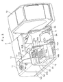
- the front cover 20 is the front cover provided between the fuel tank 12 and the backside of the article accommodating box 16.
- the front cover 20 serves to improve an external appearance by covering the portion between the fuel tank 12 and the backside of the article accommodating box 16.
- the front cover 20 is formed of a side surface portion 20A provided to be connected to the right surface plate 14C of the second plate 14 in the fuel tank 12 forward thereof and a front surface portion 20B for closing the front side of the side surface portion 20A.
- the front cover 20 is formed such that the upper side portion is narrow in width in the front and rear directions, for establishing a smooth connection between the fuel tank 12 and the article accommodating box 16.
- a step insert opening 20C is provided in the upper side portion of the front cover 20 for protruding the third step plate 19 forward, and a water supply opening 20D is provided under the step insert opening 20C for exposing a water supply port 24G of the urea water tank 24 to an outside.
- Designated at 21 is the post-treatment device provided to be connected to the exhaust pipe 7 in the engine 6.
- the post-treatment device 21 is provided with the PM trapping device 22 to be described later for trapping and removing particulate matter (PM: Particulate Matter) in an exhaust gas and the NOx purifying device 23 to be described later for purifying the nitrogen oxides (NOx) in the exhaust gas by using a urea solution as a reducing agent.
- the post-treatment device 21 is largely constituted by the PM trapping device 22 and the NOx purifying device 23.
- the PM trapping device 22 (particulate matter removing device) provided to be connected to the outlet side of the exhaust pipe 7 in the engine 6.
- the PM trapping device 22 serves to trap and remove particulate matter (PM) contained in an exhaust gas.
- the PM trapping device 22 is formed as a hollow tubular casing extending in the front and rear directions and is largely constituted by an accommodating tubular casing 22A having an upstream side (front side) connected to the exhaust pipe 7 in the engine 6, a PM trapping filter 22B accommodated in the accommodating tubular casing 22A, and an oxidation catalyst 22C arranged upstream of the PM trapping filter 22B.
- the PM trapping device 22 oxides carbon monoxides (CO), hydrocarbon (HC) and the like contained in the exhaust gas for removal and removes nitrogen oxides (NO) as nitrogen dioxides (NO 2 ) by the oxidation catalyst 22C. Further, the PM trapping filter 22B traps particulate matter contained in the exhaust gas and burns the trapped particulate matter for removal.
- the NOx purifying device 23 serves to purify nitrogen oxides (NOx) in the exhaust gas by using the urea solution.
- the NOx purifying device 23 is formed as a hollow tubular casing extending in the front and rear directions and is largely constituted by an accommodating tubular casing 23A connected to the downstream side (rear side) of the PM trapping device 22 through the connecting pipe portion 7A in the exhaust pipe 7, a urea selective reduction catalyst 23B accommodated in the upstream side of the accommodating tubular casing 23A, an oxidation catalyst 23C arranged downstream of the urea selective reduction catalyst 23B, and a urea water injection valve 23D provided upstream of the urea selective reduction catalyst 23B, for example, in the connecting pipe portion 7A in the exhaust pipe 7. Further, the urea water injection valve 23D is connected to the urea water tank 24 through a connecting pipe 28 and a supply pump 29 to be described later.
- the NOx purifying device 23 injects a urea solution into the exhaust gas by the urea water injection valve 23D, and reduces NOx in the exhaust gas by using ammonia generated from the urea solution by the urea selective reduction catalyst 23B to water and nitrogen.
- the NOx purifying device 23 removes the ammonia in the exhaust gas by the oxidation catalyst 23C.
- urea water tank 24 according to the first embodiment provided between the fuel tank 12 and the article accommodating box 16 will be described with reference to Figs. 4 , 8 , 9 and the like.
- urea water tank 24 for reserving the urea solution to be injected upstream of the urea selective reduction catalyst 23B.
- the urea water tank 24 is positioned in the outer peripheral side (front side) of the front surface plate 13B of the first plate 13 constituting the fuel tank 12 to be arranged in such a manner as to enter into the front surplus space portion 15A projected in the upper and lower directions in a range of the front flange portion 14A1 of the top surface plate 14A and projected in the right and left directions in a range of the front flange portions 14B1 and 14C1 of the left surface plate 14B and the right surface plate 14C.
- the urea water tank 24 is formed flatly in the front and rear directions as a boxy casing as having a height dimension to the extent that it can be accommodated under the third step plate 19 and is arranged along the front side of the fuel tank 12 in a state of being concealed by the front cover 20.
- the urea water tank 24 is constituted by a front surface portion 24A, a rear surface portion 24B, a left surface portion 24C, a right surface portion 24D, a top surface portion 24E, and a bottom surface portion 24F, and a water supply port 24G for supplying the urea water is provided in the top position of the front surface portion 24A.
- the cushion materials 25A and 25B respectively are fixed to the rear surface portion 24B and the bottom surface portion 24F of the urea water tank 24.
- the cushion material 25A makes contact with the front surface plate 13B of the first plate 13 constituting the fuel tank 12, and the cushion material 25B makes contact with the extension beam 5D of the revolving frame 5.
- Each of the cushion materials 25A and 25B prevents a vibration at the time of an excavating operation of the hydraulic excavator 1 and a vibration of the engine 6 from being transmitted to the urea water tank 24.
- a fixing member 26 formed by folding a long plate in a substantially U-shape is arranged in the urea water tank 24 in such a manner as to hold it from forward.
- bolts 27 inserted into both end portions of the fixing member 26 are screwed into the screw holes 13D provided in the front surface plate 13B, and thus the urea water tank 24 can be mounted on the fuel tank 12 to be disposed along the front side thereof.
- each of the cushion materials 25A and 25B can fix the fuel tank 12 and the urea water tank 24 without any gap therebetween and prevent an external vibration from being transmitted to the urea water tank 24.
- the urea water tank 24 since the urea water tank 24 according to the first embodiment is arranged between the fuel tank 12 and the article accommodating box 16 and the rear side portion thereof enters into the front surplus space portion 15A formed in the front side of the fuel tank 12, the urea water tank 24 can have a capacity to the extent that the amount of the urea water required for a long time of working can be reserved without downsizing the article accommodating box 16. In addition, the urea water tank 24 can be securely fixed to the fuel tank 12 without any gap therebetween by the respective cushion materials 25A and 25B. Meanwhile, since the urea water tank 24 is arranged along the front side of the fuel tank 12, the urea water can be easily supplied by using the respective step plates 17, 18, and 19 disposed for facilitating a fuel filling operation to the fuel tank 12. Further, since urea water tank 24 can be concealed by the front cover 20, the external appearance can be improved.
- Indicated at 28 is the connecting pipe provided for connection between the urea water tank 24 and the urea water injection valve 23D.
- the supply pump 29 is provided in the halfway of the connecting pipe 28. Therefore, the urea water in the urea water tank 24 can be supplied in a pressurized state to the urea water injection valve 23D through the connecting pipe 28.
- the hydraulic excavator 1 has the aforementioned construction, and next, an operation thereof will be explained.
- An operator boards at the cab 10 and starts the engine 6 to drive the hydraulic pump 9.
- the lever or the like for travelling By operating the lever or the like for travelling, the lower traveling structure 2 can be forwarded or retreated.
- the working mechanism 4 can be tilted to perform an excavating operation of earth and sand.
- the PM trapping device 22 removes the particulate matter.
- the NOx purifying device 23 removes the nitrogen oxides. Namely, for removing the nitrogen oxides by the NOx purifying device 23, the urea solution in the urea water tank 24 is supplied to the urea water injection valve 23D of the NOx purifying device 23 from the connecting pipe 28 by using the supply pump 29. The NOx purifying device 23 injects the urea solution as the reducing agent into the exhaust gas from the urea water injection valve 23D to generate ammonia.
- the urea selective reduction catalyst 23B reduces the nitrogen oxides to water and nitrogen and the oxidation catalyst 23C removes the ammonia in the exhaust gas. Thereafter, the purified exhaust gas is discharged to an outside, thus making it possible to remove a discharge amount of the nitrogen oxides.
- the fuel tank 12 extends the front flange portion 14A1 of the top surface plate 14A in the second plate 14 furthermore to an outside in relation to the front surface plate 13B in the first plate 13 as the side surface plate and likewise extends the front flange portion 14B1 of the left surface plate 14B and the front flange portion 14C1 of the right surface plate 14C furthermore to an outside.
- the front surplus space portion 15A projected in the upper and lower directions in a range of the front flange portion 14A1 of the top surface plate 14A and projected in the right and left directions in a range between the front flange portions 14B1 and 14C1 of the left surface plate 14B and the right surface plate 14C is formed in the front surface side of the front surface plate 13B.
- the urea water tank 24 is arranged along the fuel tank 12 in such a manner that the rear side portion thereof enters into the front surplus space portion 15A.
- the urea water tank 24 enters into the front surplus space portion 15A by using the front surplus space portion 15A formed in the fuel tank 12, and therefore, the capacity of the urea water can be increased without accommodating the urea water tank 24 into the article accommodating box 16 or downsizing the article accommodating box 16.
- the accommodating space in the article accommodating box 16 can be secured largely, tools, consumables and the like can be sufficiently accommodated therein.
- the urea water tank 24 is arranged along the fuel tank 12, an operator can have easy access to the urea water tank 24 at the time of filling the urea water therein by using the first step plate 17 provided for supplying the fuel to the fuel tank 12, and thus the operational efficiency at the time of supplying the urea water can be improved.
- the urea water tank 24 is arranged between the fuel tank 12 and the article accommodating box 16
- the space portion formed between the fuel tank 12 and the article accommodating box 16 in addition to the front surplus space portion 15A can be used as the installation space to furthermore increase the capacity.
- the fuel tank 12 according to the first embodiment is formed by connecting the U-shaped first plate 13 in which the front surface plate 13B and the rear surface plate 13C each extend upward from the both sides of the bottom surface plate 13A in the front and rear directions to the reverse U-shaped second plate 14 which has the dimension L2 in the front and rear directions larger than the dimension L1 of the first plate 13 in the front and rear directions and in which the left surface plate 14B and the right surface plate 14C each extend downward from the both sides of the top surface plate 14A in the right and left directions. Therefore, the hollow container can be easily formed by the two plates 13 and 14.
- the front flange portion 14A1 extending the furthermore to the front side in relation to the front surface plate 13B and the rear flange portion 14A2 extending furthermore to the rear side in relation to the rear surface plate 13C can be formed in the top surface plate 14A by a dimension difference between the first plate 13 and the second plate 14 in the front and rear directions.
- the front flange portions 14B1 and 14C1 extending furthermore to the front side in relation to the front surface plate 13B and the rear flange portions 14B2 and 14C2 extending furthermore to the rear side in relation to the rear surface plate 13C can be formed in the left surface plate 14B and the right surface plate 14C.
- the front surplus space portion 15A projected in the upper and lower directions and in the right and left directions in a range of the front flange portions 14A1, 14B1, and 14C1 can be formed, and the rear surplus space portion 15B projected in the upper and lower directions and in the right and left directions in a range of the rear flange portions 14A2, 14B2, and 14C2 can be formed.
- the urea water tank 24 can be positioned in the outer peripheral side of the front surface plate 13B of the fuel tank 12 to be arranged in such a manner as to enter into the front surplus space portion 15A projected in the upper and lower directions in a range of the front flange portion 14A1 of the top surface plate 14A and projected in the right and left directions in a range between the front flange portions 14B1 and 14C1 of the left surface plate 14B and in the right surface plate 14C. Consequently, the urea water tank 24 having a large tank capacity can be arranged without sacrificing the installation space of the circumferential members such as the article accommodating box 16.
- the front cover 20 for covering the portion between the fuel tank 12 and the article accommodating box 16 is provided between the fuel tank 12 and the article accommodating box 16, and the urea water tank 24 is arranged in a state of being concealed by the front cover 20.
- the urea water tank 24 can be concealed by the front cover 20 to improve the external appearance.
- the cushion material 25A is provided between the fuel tank 12 and the urea water tank 24, and the cushion material 25B is provided between the revolving frame 5 and the urea water tank 24.
- Fig. 11 shows a second embodiment according to the present invention.
- the present embodiment is characterized in that a urea water tank is formed to be higher than a third step plate.
- the component elements that are identical to those of the foregoing first embodiment will be simply denoted by the same reference numerals to avoid repetitions of similar explanations.
- a front cover in the second embodiment used instead of the front cover 20 according to the first embodiment.
- the front cover 31 is formed of a side surface portion (not shown) and a front surface portion 31B in the substantially same way as the front cover 20 according to the first embodiment.
- a third step plate 32 is directly mounted to the front cover 31 according to the second embodiment without the step insert opening and a water supply opening 31C is provided in the front cover 31 at a position above the mounting portion of the third step plate 32.
- Denoted at 33 is a urea water tank according to the second embodiment provided inside the front cover 31.
- the urea water tank 33 is arranged along the fuel tank 12 in such a manner as to enter into the front surplus space portion 15A.
- the urea water tank 33 is, in the substantially same way as the urea water tank 24 according to the first embodiment, formed as a boxy casing by a front surface portion 33A, a rear surface portion 33B, a left surface portion 33C, a right surface portion (not shown), a top surface portion 33D, and a bottom surface portion 33E.
- the urea water tank 33 according to the second embodiment differs from the urea water tank 24 according to the first embodiment on the two points that it is formed to have a height dimension larger than that of the third step plate 32 and that a water supply port 33F is provided in the top surface portion 33D.
- the second embodiment can also obtain the substantially same effect as that of the first embodiment mentioned before.
- the tank capacity thereof can be furthermore increased.
- Fig. 12 shows an example useful for understanding the present invention.
- the present example is characterized in that a urea water tank serves also as the front cover.
- the component elements that are identical to those of the foregoing first embodiment will be simply denoted by the same reference numerals to avoid repetitions of similar explanations.
- Denoted at 41 is a urea water tank in this example used instead of the urea water tank 24 according to the first embodiment.
- the urea water tank 41 differs from the urea water tank 24 according to the first embodiment and is provided in a state of being exposed to an outside. Further, the urea water tank 41 is positioned between the fuel tank 12 and the article accommodating box 16 and is arranged along the fuel tank 12 in a state in which the rear side portion thereof enters into the front surplus space portion 15A.
- the urea water tank 41 is formed as an irregular-shaped angular tubular casing by a front surface portion 41A, a rear surface portion 41B, a left surface portion 41C, a right surface portion (not shown), a top surface portion 41D, and a bottom surface portion 41E.
- the urea water tank 41 has a dimension in the front and rear directions slightly smaller than an interval dimension between the front surface plate 13B of the first plate 13 constituting the fuel tank 12 and the rear surface of the article accommodating box 16. Therefore, the urea water tank 41 can be formed to be large in size in the front and rear directions.
- the upper side portion of the front surface portion 41A is inclined backward in the upper direction in the substantially same way as the upper side portion of the front cover 20 according to the first embodiment and establishes a smooth connection between the fuel tank 12 and the article accommodating box 16. Therefore, the urea water tank 41 serves also as the front cover for establishing the smooth connection on the external appearance between the fuel tank 12 and the article accommodating box 16. Meanwhile, a water supply port 41F is provided in the top surface portion 41D and a third step plate 42 is mounted on the upper side portion of the front surface portion 41A.
- the operational effect substantially similar to that of the first embodiment described before can be obtained.
- the tank capacity of the urea water tank 41 can be maximized in a range of the front surplus space portion 15A.
- the urea water tank 41 serves also as the front cover, the number of the components can be reduced to improve assembly operability and the like.
- Fig. 13 shows another example useful for understanding the present invention.
- the example is characterized in that a side surface plate forming an outer peripheral surface of an oil reservoir tank is formed in a cylindrical shape.
- the component elements that are identical to those of the foregoing first embodiment will be simply denoted by the same reference numerals to avoid repetitions of similar explanations.
- the fuel tank 51 is a fuel tank as an oil reservoir tank according to the example used instead of the fuel tank 12 according to the first embodiment.
- the fuel tank 51 is formed by a cylindrical side surface plate 51A forming an outer peripheral surface, a rectangular bottom surface plate 51B closing a bottom surface of the side surface plate 51A, and a rectangular top surface plate 51C closing a top surface of the side surface plate 51A and having a flange portion 51C1 extending furthermore to an outside in relation to the side surface plate 51A.
- a ring-shaped surplus space portion 52 projected in the upper and lower directions in a range of the flange portion 51C1 of the top surface plate 51C is formed in an outer peripheral surface side of the side surface plate 51A.
- urea water tank 53 Denoted at 53 is a urea water tank 53 according to the example provided along the front side of the fuel tank 51.
- the urea water tank 53 is, in the substantially same way as the urea water tank 24 according to the first embodiment, formed as a boxy casing by a front surface portion 53A, a rear surface portion 53B, a left surface portion 53C, a right surface portion 53D, a top surface portion 53E, and a bottom surface portion 53F.
- a rear surface portion 53B facing the side surface plate 51A of the fuel tank 51 formed in a cylindrical shape is formed in a concave arc shape in such a manner as to correspond to the cylindrical shape of the side surface plate 51A.
- a water supply port 53G is provided in the upper side position of the front surface portion 53A.
- a cushion material 54A is fixed to the rear surface portion 53B and a cushion material 54B is fixed to the bottom surface portion 53F.
- the cushion material 54A is made in contact with the side surface plate 51A of the fuel tank 51 and the cushion material 54B is made in contact with the extension beam 5D of the revolving frame 5.
- the urea water tank 53 is arranged in such a manner as to enter into the front side portion between the fuel tank 51 and the article accommodating box 16 among the ring-shaped surplus space portion 52 (portion corresponding to a position of the front surplus space portion 15A in the first embodiment).
- the urea water tank 53 can be fixed in such a manner as to be positioned along the front side of the fuel tank 51 by mounting a fixing member 55 formed by folding a long plate in a substantially U-shape on a belt 56 wound around the side surface plate 51A by using bolts 57.
- the operational effect substantially similar to that of the first embodiment described before can be obtained.
- the urea water tank 53 can be arranged also to the fuel tank 51 equipped with the cylindrical side surface plate 51A in a state of having entered into the front side in the ring-shaped surplus space portion 52.
- Fig. 14 shows a fifth embodiment according to the present invention.
- the present embodiment is characterized in that a water supply opening is arranged closer to the right side of a front cover.
- the component elements that are identical to those of the foregoing first embodiment will be simply denoted by the same reference numerals to avoid repetitions of similar explanations.
- the front cover 61 is formed of a side surface portion 61A and a front surface portion 61B in the substantially same way as the front cover 20 according to the first embodiment, and a step insert opening 61C is provided in the upper side portion of the front surface portion 61B to be positioned closer to the left side for protruding the third step plate 19 forward.
- the front cover 61 according to the fifth embodiment differs from the front cover 20 according to the first embodiment in that a water supply opening 61D for exposing a water supply port 62A of a urea water tank 62 to be described later to an outside is provided closer to the right side.
- a lid member 61E for covering the water supply opening 61D is mounted in the water supply opening 61D of the front cover 61 to be capable of opening and closing. Therefore, the lid member 61E can cover the water supply port 62A for protection and improve an external appearance.
- Denoted at 62 is the urea water tank (illustrated in a dotted line) according to the fifth embodiment provided in the front cover 61.
- the urea water tank 62 is constructed in the substantially same way as the urea water tank 24 according to the first embodiment.
- the urea water tank 62 according to the fifth embodiment differs from the urea water tank 24 according to the first embodiment in that the water supply port 62A is provided closer to the right side to correspond to the water supply opening 61D of the front cover 61.
- the operational effect substantially similar to that of the first embodiment can be obtained.
- the water supply opening 61D of the front cover 61 is provided closer to the right side, different from the step insert opening 61C provided closer to the left side. Therefore, the water supply can be smoothly carried out from the water supply port 62A to the urea water tank 62 without interruption of the third step plate 19. Further, since the lid member 61E is mounted to the water supply opening 61D, the lid member 61E can cover the water supply port 62A for protection and improve an external appearance.
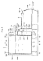
- Fig. 15 shows a sixth embodiment according to the present invention.
- the present embodiment is characterized in that a front surplus space portion is provided only in the front side of an oil reservoir tank.
- the component elements that are identical to those of the foregoing first embodiment will be simply denoted by the same reference numerals to avoid repetitions of similar explanations.
- the fuel tank 71 is, in the substantially same way as the fuel tank 12 according to the first embodiment, constituted by a first plate 72 formed by folding one sheet of a metallic plate carved out in a strip shape in a U-shape and a second plate 73 formed by folding one sheet of a metallic plate carved out in a strip shape in a reverse U-shape.
- the first plate 72 is formed of a bottom surface plate 72A, a front surface plate 72B, and a rear surface plate 72C.
- the second plate 73 is formed of a top surface plate 73A, a left surface plate 73B, and a right surface plate (not shown).
- the first plate 72 and the second plate 73 constituting the fuel tank 71 are constructed in such a manner that the front surface plate 72B and the rear surface plate 72C of the first plate 72 are arranged to be shifted by 90 degrees in the circumferential direction between the left surface plate 73B and the right surface plate of the second plate 73 for air and liquid-tightly welding a peripheral edge of the first plate 72 to the second plate 73.
- the fuel tank 71 forms a side surface plate of an angular tubular shape whose outer peripheral surface is formed by the front surface plate 72B and the rear surface plate 72C of the first plate 72, and the left surface plate 73B and the right surface plate of the second plate 73.
- the top surface plate 73A, the left surface plate 73B, and the right surface plate of the second plate 73 are constructed to extend furthermore to the front side in relation to the front surface plate 72B of the first plate 72, whereby the front portions of the top surface plate 73A, the left surface plate 73B, and the right surface plate constitute front flange portions 73A1 and 73B1.
- the front flange portions 73A1 and 73B1 is formed by the dimension difference caused by making a dimension of the second plate 73 in the front and rear directions longer than a dimension of the first plate 72 in the front and rear directions.
- a flange portion is not formed in each of the top surface plate 73A, the left surface plate 73B, and the right surface plate of the second plate 73 because of arranging the rear surface plate 72C of the first plate 72 to be substantially coincident with rear end edges 73A2 and 73B2 of the top surface plate 73A, the left surface plate 73B, and the right surface plate of the second plate 73 in the front and rear directions.
- Denoted at 74 is a front surplus space portion formed in a front side position of the fuel tank 71, and the front surplus space portion 74 corresponds to a portion (portion shown in a lattice shape) projected in the upper and lower directions in a range of the front flange portion 73A1 of the top surface plate 73A and projected in the right and left directions in a range between the front flange portion 73B1 of the left surface plate 73B and the front flange portion of the right surface plate in the second plate 73.
- the urea water tank 24 is arranged in a state of having entered into the front surplus space portion 74.
- the operational effect substantially similar to that of the first embodiment described before can be obtained.
- the front surplus space portion 74 is formed in the front side position of the fuel tank 71, the urea water tank 24 can be accommodated inside the front surplus space portion 74.
- the surplus space portion (flange portion) is not formed in the rear side portion of the fuel tank 71, the rear surface plate 72C of the first plate 72 can be arranged to be closer to the front surface of the operating oil tank 11 to achieve an increase in the tank capacity of the fuel tank 71 and the downsizing of the upper revolving structure 3, and the like.
- a urea water tank 81 may be constructed to be bolted to the fuel tank 12 and the revolving frame 5 by using mount brackets 82. This construction may be applied similarly to the other embodiments.
- the explanation is made on the first embodiment by taking a case where the fuel tank 12 for reserving fuel is shown as the reservoir tank and the urea water tank 24 is arranged in the front side of the fuel tank 12, as an example.
- the present invention is not limited to this particular example, and may be constructed such that the surplus space portion is provided in the operating oil tank 11 and the urea water tank 24 is arranged in such a manner as to enter into the surplus space portion. This construction may be applied similarly to the other embodiments.
- each of the embodiments described above exemplifies the crawler type hydraulic excavator 1 as the construction machine.
- the present invention is not limited to this particular example, and may be applied to a wheel type hydraulic excavator.
- the present invention may be widely applied to other construction machines such as a wheel loader and a hydraulic crane.
- Features, components and specific details of the structures of the above-described embodiments may be exchanged or combined to form further embodiments optimized for the respective application. As far as those modifications are readily apparent for an expert skilled in the art they shall be disclosed implicitly by the above description without specifying explicitly every possible combination, for the sake of conciseness of the present description.
Claims (4)
- Machine de construction comprenant : un châssis de support (5) formant un élément structurel de support pour une structure de déplacement (2, 3) ;
un moteur (6) monté sur le côté arrière dudit châssis de support (5) ; une cabine (10) qui est positionnée du côté avant dudit châssis de support (5) pour être agencée dans un côté dans les directions droite/gauche de celui-ci et au bord de laquelle embarque un opérateur ;
un récipient réservoir d'huile (12, 71) agencé dans ledit châssis de support (5) dans l'autre côté dans les directions droite/gauche de celui-ci pour mettre en réserve du carburant à fournir audit moteur (6) ou pour mettre en réserve de l'huile fonctionnelle à utiliser dans un système hydraulique ;
une boîte de logement d'articles (16) prévue sur ledit châssis de support (5) pour être positionnée en avant dudit récipient réservoir d'huile (12, 71) ;
un dispositif de purification de NOx (23) prévu dans un tube d'échappement (7) dudit moteur (6) et équipé d'un catalyseur de réduction sélective à base d'urée (23B) pour supprimer les oxydes d'azote dans un gaz d'échappement ;
un réservoir urée/eau (24, 33, 62, 81) formé d'un conteneur creux pour mettre en réserve un mélange urée/eau à titre d'agent réducteur ; et
un tube de connexion (28) établissant une connexion entre ledit réservoir urée/eau (24, 33, 62, 81) et ledit tube d'échappement (7) dudit moteur (6) ;
dans laquelle ledit récipient réservoir d'huile (12, 71) est formé d'un tube angulaire ou d'une plaque de surface latérale cylindrique (13B, 13C, 14B, 14C, 72B, 72C, 73B) formant une surface périphérique extérieure, une plaque de surface inférieure (13A, 72A) fermant une surface inférieure de ladite plaque de surface latérale (13B, 13C, 14B, 14C, 72B, 72C, 73B), et une plaque de surface supérieure (14A, 73A) fermant une surface supérieure de ladite plaque de surface latérale (13B, 13C, 14B, 14C, 72B, 72C, 73B) et incluant une portion en bride (14A1, 14A2, 73A1) s'étendant plus loin vers l'extérieur en relation à ladite plaque de surface latérale (13B, 13C, 14B, 14C, 72B, 72C, 73B) ;
une portion formant espace supplémentaire (15A, 15B, 74) est formée dans un côté de la surface périphérique extérieure de ladite plaque de surface latérale (13B, 13C, 14B, 14C, 72B, 72C, 73B) pour se projeter dans la direction vers le haut et la direction vers le bas dans une zone de ladite portion en bride (14A1, 14A2, 73A1) de ladite plaque de surface supérieure (14A, 73A) ;
ladite machine de construction étant caractérisée en ce que :ledit réservoir urée/eau (24, 33, 62, 81) est agencé le long dudit récipient réservoir d'huile (12, 71) de manière à entrer dans ladite portion formant espace supplémentaire (15A, 74) formée entre un côté avant dudit récipient réservoir d'huile (12, 71) et ladite boîte de logement d'articles (16) à l'intérieur de ladite portion formant espace supplémentaire (15A, 15B, 74) ; etun couvercle avant (20, 31, 61), qui couvre ledit réservoir urée/eau (24, 33, 62, 81) dans une situation dans laquelle ledit réservoir urée/eau (24, 33, 62, 81) est dissimulé vis-à-vis de l'extérieur, est prévu entre ledit récipient réservoir d'huile (12, 71) et ladite boîte de logement d'articles (16). - Machine de construction selon la revendication 1, dans laquelle ledit récipient réservoir d'huile (12, 71) est formé sous une forme tubulaire angulaire en connectant une première plaque (13, 72) formée sous une forme en U dans laquelle une plaque de surface avant (13B, 72B) et une plaque de surface arrière (13C, 72C) s'étendent respectivement vers le haut depuis les deux côtés de ladite plaque de surface inférieure (13A, 72A) dans les directions avant/arrière vers une seconde plaque (14, 73) ayant une dimension (L2) dans les directions avant/arrière plus grande qu'une dimension (L1) de ladite première plaque (13, 72) dans les directions avant/arrière et formée sous une forme en U inversé, dans laquelle une plaque de surface gauche (14B, 73B) et une plaque de surface droite (14C) s'étendent respectivement vers le bas depuis les deux côtés de ladite plaque de surface supérieure (14A, 73A) dans les directions droite/gauche,
une portion en bride avant (14A1, 73A1) est formée dans ladite plaque de surface supérieure (14A, 73A) pour s'étendre plus loin vers le côté avant en relation à ladite plaque de surface avant (13B, 72B) à raison d'une différence de dimension entre ladite première plaque (13, 72) et ladite seconde plaque (14, 73) dans les directions avant/arrière, et
ledit réservoir urée/eau (24, 33, 41, 62, 81) est positionné dans un côté périphérique extérieur de ladite plaque de surface avant (13B, 72B) dudit récipient réservoir d'huile (12, 71) pour être agencé de manière à entrer dans une portion formant espace supplémentaire avant (15A, 74) qui se projette dans les directions vers le haut et vers le bas dans une zone de ladite portion en bride avant (14A1, 73A1) de ladite plaque de surface supérieure (14A, 73A. - Machine de construction selon la revendication 1, dans laquelle ledit récipient réservoir d'huile (12, 71) est formé sous une forme tubulaire angulaire en connectant une première plaque (13, 72) formée sous une forme en U dans laquelle une plaque de surface avant (13B, 72B) et une plaque de surface arrière (13C, 72C) s'étendent respectivement vers le haut depuis les deux côtés de ladite plaque de surface inférieure (13A, 72A) dans les directions avant/arrière vers une seconde plaque (14, 73) ayant une dimension (L2) dans lés directions avant/arrière plus grande qu'une dimension (L1) de ladite première plaque (13, 72) dans les directions avant/arrière et formée sous une forme en U inversé, dans laquelle une plaque de surface gauche (14B, 73B) et une plaque de surface droite (14C) s'étendent respectivement vers le bas depuis les deux côtés de ladite plaque de surface supérieure (14A, 73A) dans les directions droite/gauche,
une portion en bride avant (14A1, 14B1, 14C1, 73A1, 73B1) est formée dans chacune de ladite plaque de surface supérieure (14A, 73A), de ladite plaque de surface gauche (14B, 73B) et de ladite plaque de surface droite (14C) pour s'étendre plus loin vers le côté avant en relation à ladite plaque de surface avant (13B, 72B) à raison d'une différence de dimension entre ladite première plaque (13, 72) et ladite seconde plaque (14, 73) dans les directions avant/arrière, et
ledit réservoir urée/eau (24, 33, 41, 62, 81) est positionné dans un côté périphérique extérieur de ladite plaque de surface avant (13B, 72B) dudit récipient réservoir d'huile (12, 71) pour être agencé de manière à entrer dans une portion formant espace supplémentaire avant (15A, 74) qui se projette dans la direction vers le haut et la direction vers le bas dans une zone de ladite portion en bride avant (14A1, 73A1) de ladite plaque de surface supérieure (14A, 73A) et qui se projette dans les directions droite/gauche dans une zone entre lesdites portions en bride avant (14B1, 14C1, 73B1) de ladite plaque de surface gauche (14B, 73B) et ladite plaque de surface droite (14C). - Machine de construction selon l'une au moins des revendications 1, 2 et 3, dans laquelle un matériau formant coussin (25A) est prévu entre ladite plaque de surface latérale (13B, 72B) dudit récipient réservoir d'huile (12, 71) et une portion de surface arrière (24B, 33B) dudit réservoir urée/eau (24, 33, 62) pour absorber des vibrations externes.
Applications Claiming Priority (1)
| Application Number | Priority Date | Filing Date | Title |
|---|---|---|---|
| JP2010207860A JP5562777B2 (ja) | 2010-09-16 | 2010-09-16 | 建設機械 |
Publications (2)
| Publication Number | Publication Date |
|---|---|
| EP2431536A1 EP2431536A1 (fr) | 2012-03-21 |
| EP2431536B1 true EP2431536B1 (fr) | 2015-05-27 |
Family
ID=44872173
Family Applications (1)
| Application Number | Title | Priority Date | Filing Date |
|---|---|---|---|
| EP11181497.6A Active EP2431536B1 (fr) | 2010-09-16 | 2011-09-15 | Machine de construction |
Country Status (5)
| Country | Link |
|---|---|
| US (1) | US8708087B2 (fr) |
| EP (1) | EP2431536B1 (fr) |
| JP (1) | JP5562777B2 (fr) |
| KR (1) | KR20120029990A (fr) |
| CN (1) | CN102444148B (fr) |
Families Citing this family (74)
| Publication number | Priority date | Publication date | Assignee | Title |
|---|---|---|---|---|
| GB0913581D0 (en) * | 2009-08-05 | 2009-09-16 | Agco Gmbh | Tractors |
| JP2011247232A (ja) * | 2010-05-31 | 2011-12-08 | Caterpillar Sarl | 作業機械 |
| US8905165B1 (en) | 2010-08-06 | 2014-12-09 | David Johnstone | Track driven sub-base assembly |
| US8550193B1 (en) * | 2010-08-06 | 2013-10-08 | David Johnstone | Track driven sub-base assembly |
| US9528447B2 (en) | 2010-09-14 | 2016-12-27 | Jason Eric Green | Fuel mixture control system |
| JP5630216B2 (ja) * | 2010-10-29 | 2014-11-26 | コベルコ建機株式会社 | 建設機械 |
| JP2012171596A (ja) * | 2011-02-24 | 2012-09-10 | Hitachi Constr Mach Co Ltd | 建設機械 |
| CN102781705B (zh) | 2011-03-02 | 2014-03-12 | 株式会社小松制作所 | 储油罐以及建设车辆 |
| US8998234B2 (en) * | 2011-08-09 | 2015-04-07 | Hitachi Construction Machinery Co., Ltd. | Construction machine |
| US9421861B2 (en) | 2011-09-16 | 2016-08-23 | Gaseous Fuel Systems, Corp. | Modification of an industrial vehicle to include a containment area and mounting assembly for an alternate fuel |
| US9248736B2 (en) * | 2011-09-16 | 2016-02-02 | Gaseous Fuel Systems, Corp. | Modification of an industrial vehicle to include a containment area and mounting assembly for an alternate fuel |
| US8882071B2 (en) * | 2011-09-16 | 2014-11-11 | Jason Green | Modification of an industrial vehicle to include a containment area and mounting assembly for an alternate fuel |
| US10086694B2 (en) | 2011-09-16 | 2018-10-02 | Gaseous Fuel Systems, Corp. | Modification of an industrial vehicle to include a containment area and mounting assembly for an alternate fuel |
| US8820289B2 (en) | 2011-09-27 | 2014-09-02 | Jason Green | Module containment of fuel control system for a vehicle |
| US8881933B2 (en) | 2011-10-17 | 2014-11-11 | Jason E. Green | Vehicle mounting assembly for a fuel supply |
| US9278614B2 (en) | 2011-10-17 | 2016-03-08 | Gaseous Fuel Systems, Corp. | Vehicle mounting assembly for a fuel supply |
| US9738154B2 (en) | 2011-10-17 | 2017-08-22 | Gaseous Fuel Systems, Corp. | Vehicle mounting assembly for a fuel supply |
| CN104169502B (zh) * | 2012-03-16 | 2016-08-10 | 日立建机株式会社 | 工程机械 |
| JP5891111B2 (ja) * | 2012-05-31 | 2016-03-22 | ヤンマー株式会社 | 作業車両 |
| JP5181076B1 (ja) * | 2012-08-03 | 2013-04-10 | 株式会社小松製作所 | 油圧ショベル |
| JP5859933B2 (ja) * | 2012-08-31 | 2016-02-16 | 日立建機株式会社 | 建設機械 |
| FR2995831B1 (fr) | 2012-09-25 | 2014-08-29 | Renault Sa | Implantation de pipe de reservoir d'uree dans un vehicule utilitaire a moteur diesel et vehicule correspondant |
| JP5442829B1 (ja) * | 2012-10-16 | 2014-03-12 | 株式会社小松製作所 | 油圧ショベル |
| JP5439634B1 (ja) | 2012-10-30 | 2014-03-12 | 株式会社小松製作所 | 排気ガス後処理装置を搭載した建設車両 |
| WO2014069026A1 (fr) * | 2012-10-30 | 2014-05-08 | 株式会社小松製作所 | Véhicule de chantier équipé d'un dispositif de post-traitement des gaz d'échappement |
| CN103687996B (zh) * | 2012-12-20 | 2014-12-31 | 株式会社小松制作所 | 机动平地机 |
| JP5336648B1 (ja) | 2012-12-20 | 2013-11-06 | 株式会社小松製作所 | モータグレーダ |
| US9696066B1 (en) | 2013-01-21 | 2017-07-04 | Jason E. Green | Bi-fuel refrigeration system and method of retrofitting |
| DE112013000122B4 (de) * | 2013-02-15 | 2017-06-14 | Komatsu Ltd. | Hydraulikbagger |
| US9469970B2 (en) * | 2013-02-18 | 2016-10-18 | Komatsu Ltd. | Hydraulic excavator |
| JP5761245B2 (ja) * | 2013-04-02 | 2015-08-12 | コベルコ建機株式会社 | 作業機械 |
| US20150025774A1 (en) | 2013-07-22 | 2015-01-22 | Jason Green | Fuel mixture system and assembly |
| US9845744B2 (en) | 2013-07-22 | 2017-12-19 | Gaseous Fuel Systems, Corp. | Fuel mixture system and assembly |
| US9394841B1 (en) | 2013-07-22 | 2016-07-19 | Gaseous Fuel Systems, Corp. | Fuel mixture system and assembly |
| US9267268B2 (en) | 2013-09-25 | 2016-02-23 | Komatsu Ltd. | Motor grader |
| CN103797192B (zh) * | 2013-09-27 | 2015-10-21 | 株式会社小松制作所 | 还原剂箱及作业车辆 |
| EP3056613B1 (fr) | 2013-10-08 | 2023-08-30 | Sumitomo (S.H.I.) Construction Machinery Co., Ltd. | Pelle |
| JP5867485B2 (ja) * | 2013-11-20 | 2016-02-24 | コベルコ建機株式会社 | 建設機械 |
| DE102013019448A1 (de) | 2013-11-21 | 2015-06-03 | Wirtgen Gmbh | Selbstfahrende Baumaschine |
| CN103670612B (zh) * | 2013-12-20 | 2016-06-01 | 凯龙高科技股份有限公司 | 集成化汽车scr后处理系统尿素溶液供给装置 |
| JP6260284B2 (ja) * | 2014-01-09 | 2018-01-17 | コベルコ建機株式会社 | 建設機械のサイドフレーム |
| JP5949793B2 (ja) * | 2014-01-17 | 2016-07-13 | コベルコ建機株式会社 | 建設機械 |
| JP6303717B2 (ja) * | 2014-03-28 | 2018-04-04 | コベルコ建機株式会社 | 建設機械 |
| JP6218674B2 (ja) * | 2014-05-28 | 2017-10-25 | 株式会社クボタ | 作業車 |
| WO2015059982A1 (fr) | 2014-08-08 | 2015-04-30 | 株式会社小松製作所 | Pelle hydraulique |
| JP5719092B1 (ja) * | 2014-08-25 | 2015-05-13 | 株式会社小松製作所 | ブルドーザ |
| US9254849B1 (en) | 2014-10-07 | 2016-02-09 | Gaseous Fuel Systems, Corp. | Device and method for interfacing with a locomotive engine |
| US9931929B2 (en) | 2014-10-22 | 2018-04-03 | Jason Green | Modification of an industrial vehicle to include a hybrid fuel assembly and system |
| US9428047B2 (en) * | 2014-10-22 | 2016-08-30 | Jason Green | Modification of an industrial vehicle to include a hybrid fuel assembly and system |
| JP6307019B2 (ja) * | 2014-11-28 | 2018-04-04 | 日立建機株式会社 | 建設機械 |
| CN104500461B (zh) * | 2014-12-16 | 2016-08-17 | 江苏柳工机械有限公司 | 挖掘装载机液压油箱 |
| DE202014010518U1 (de) * | 2014-12-18 | 2015-11-09 | Hamm Ag | Bodenbearbeitungsmaschine, insbesondere Bodenverdichter |
| US9885318B2 (en) | 2015-01-07 | 2018-02-06 | Jason E Green | Mixing assembly |
| US9404238B1 (en) * | 2015-01-10 | 2016-08-02 | Bauer Maschinen Gmbh | Construction machine |
| JP6038967B2 (ja) * | 2015-01-22 | 2016-12-07 | 住友建機株式会社 | 油圧ショベル |
| DE112015000013T5 (de) * | 2015-01-29 | 2016-11-10 | Komatsu Ltd. | Arbeitsfahrzeug |
| KR101809577B1 (ko) * | 2015-02-23 | 2017-12-15 | 가부시키가이샤 고마쓰 세이사쿠쇼 | 유압 셔블 |
| JP6529799B2 (ja) * | 2015-03-20 | 2019-06-12 | 住友建機株式会社 | 小旋回型ショベル |
| JP6495082B2 (ja) * | 2015-04-17 | 2019-04-03 | 日立建機株式会社 | 建設機械 |
| IN2015DN07856A (fr) * | 2015-05-21 | 2015-10-23 | Komatsu Mfg Co Ltd | |
| JP6588239B2 (ja) * | 2015-06-03 | 2019-10-09 | 日立建機株式会社 | 建設機械 |
| JP6497737B2 (ja) * | 2015-06-18 | 2019-04-10 | キャタピラー エス エー アール エル | 建設機械におけるカウンタウエイト支持構造 |
| US20160040389A1 (en) * | 2015-10-20 | 2016-02-11 | Caterpillar Sarl | Serviceable anti-skid structure |
| JP2017081259A (ja) * | 2015-10-23 | 2017-05-18 | ヤンマー株式会社 | 作業車両 |
| JP6280536B2 (ja) * | 2015-12-11 | 2018-02-14 | ヤンマー株式会社 | トラクタ |
| JP2016065542A (ja) * | 2015-12-11 | 2016-04-28 | ヤンマー株式会社 | 作業車両 |
| US10196953B2 (en) * | 2016-04-22 | 2019-02-05 | Lund, Inc. | Tank cover for diesel exhaust fluid tank |
| JP6216413B2 (ja) * | 2016-06-16 | 2017-10-18 | ヤンマー株式会社 | トラクタ |
| JP6619378B2 (ja) * | 2017-03-30 | 2019-12-11 | ヤンマー株式会社 | クローラトラクタ |
| JP6965804B2 (ja) | 2018-03-28 | 2021-11-10 | コベルコ建機株式会社 | 建設機械 |
| WO2020031213A1 (fr) * | 2018-08-10 | 2020-02-13 | Hero MotoCorp Limited | Système d'échappement |
| JP7166202B2 (ja) * | 2019-02-28 | 2022-11-07 | 日立建機株式会社 | 建設機械 |
| JP6922960B2 (ja) * | 2019-09-26 | 2021-08-18 | コベルコ建機株式会社 | 建設機械 |
| US20230044506A1 (en) * | 2021-08-06 | 2023-02-09 | Anthony Kelly | Fuel/diesel exhaust fluid combination auxiliary tank |
Family Cites Families (25)
| Publication number | Priority date | Publication date | Assignee | Title |
|---|---|---|---|---|
| JPS5936500Y2 (ja) * | 1979-10-25 | 1984-10-08 | 株式会社クボタ | 作業車のオイルタンク構造 |
| JPH09235752A (ja) | 1996-03-04 | 1997-09-09 | Kubota Corp | 旋回作業機のボンネット装置 |
| JP4130723B2 (ja) * | 2000-03-21 | 2008-08-06 | 日立建機株式会社 | 建設機械 |
| JP2002061223A (ja) * | 2000-08-21 | 2002-02-28 | Hitachi Constr Mach Co Ltd | 建設機械 |
| JP2003020936A (ja) * | 2001-07-03 | 2003-01-24 | Komatsu Ltd | NOx還元触媒用液体還元剤タンクの配置構造 |
| CN100402762C (zh) * | 2002-03-26 | 2008-07-16 | 神钢建设机械株式会社 | 小型摇摆式挖掘机 |
| JP3751962B2 (ja) * | 2003-09-05 | 2006-03-08 | 日産ディーゼル工業株式会社 | エンジンの排気浄化装置 |
| JP2005140305A (ja) * | 2003-11-10 | 2005-06-02 | Hitachi Constr Mach Co Ltd | 建設機械のタンクの構造 |
| CN2777057Y (zh) * | 2005-01-10 | 2006-05-03 | 牛根元 | 拖拉机变型挖掘机 |
| JP4233595B2 (ja) | 2005-01-31 | 2009-03-04 | 株式会社小松製作所 | 作業車両 |
| US7388301B2 (en) * | 2005-10-12 | 2008-06-17 | Kobelco Construction Machinery Co., Ltd. | Construction machine |
| JP2008240676A (ja) * | 2007-03-28 | 2008-10-09 | Komatsu Ltd | 建設車両 |
| JP4966100B2 (ja) * | 2007-05-31 | 2012-07-04 | 日立建機株式会社 | 建設機械 |
| WO2009001587A1 (fr) * | 2007-06-26 | 2008-12-31 | Hitachi Construction Machinery Co., Ltd. | Machine de construction autotractée |
| JP4900163B2 (ja) * | 2007-09-26 | 2012-03-21 | コベルコ建機株式会社 | 建設機械 |
| JP4928474B2 (ja) * | 2008-01-08 | 2012-05-09 | 日立建機株式会社 | 建設機械のNOx低減装置の配設構造 |
| JP2009166713A (ja) * | 2008-01-17 | 2009-07-30 | Kobelco Contstruction Machinery Ltd | 建設機械のタンク |
| JP5101324B2 (ja) * | 2008-02-07 | 2012-12-19 | 日立建機株式会社 | 建設機械のNOx低減装置の配設構造 |
| US8490821B2 (en) * | 2008-04-21 | 2013-07-23 | Mack Trucks, Inc. | Apparatus for separately containing different fluids |
| EP2302180B1 (fr) * | 2008-07-10 | 2014-04-30 | Hitachi Construction Machinery Co., Ltd | Machine de construction |
| JP5107822B2 (ja) * | 2008-08-11 | 2012-12-26 | 日立建機株式会社 | 排気ガス浄化装置 |
| US8904766B2 (en) * | 2008-09-08 | 2014-12-09 | Hitachi Construction Machinery Co, Ltd. | Exhaust gas treatment device |
| JP5152027B2 (ja) * | 2009-02-13 | 2013-02-27 | コベルコ建機株式会社 | ツールボックス構造 |
| JP4937291B2 (ja) * | 2009-03-30 | 2012-05-23 | 住友建機株式会社 | 建設機械 |
| JP2011247232A (ja) * | 2010-05-31 | 2011-12-08 | Caterpillar Sarl | 作業機械 |
-
2010
- 2010-09-16 JP JP2010207860A patent/JP5562777B2/ja not_active Expired - Fee Related
-
2011
- 2011-06-28 KR KR1020110062807A patent/KR20120029990A/ko not_active Application Discontinuation
- 2011-07-13 US US13/181,820 patent/US8708087B2/en active Active
- 2011-09-14 CN CN201110277009.3A patent/CN102444148B/zh active Active
- 2011-09-15 EP EP11181497.6A patent/EP2431536B1/fr active Active
Also Published As
| Publication number | Publication date |
|---|---|
| CN102444148B (zh) | 2015-07-08 |
| US8708087B2 (en) | 2014-04-29 |
| JP5562777B2 (ja) | 2014-07-30 |
| EP2431536A1 (fr) | 2012-03-21 |
| KR20120029990A (ko) | 2012-03-27 |
| CN102444148A (zh) | 2012-05-09 |
| US20120067660A1 (en) | 2012-03-22 |
| JP2012062693A (ja) | 2012-03-29 |
Similar Documents
| Publication | Publication Date | Title |
|---|---|---|
| EP2431536B1 (fr) | Machine de construction | |
| US9027697B2 (en) | Construction machine | |
| JP5012406B2 (ja) | 建設機械 | |
| KR101885233B1 (ko) | 건설 기계 | |
| EP2826921B1 (fr) | Machine de construction | |
| KR101970262B1 (ko) | 건설 기계 | |
| EP2474672A1 (fr) | Véhicule de travail de type à roues | |
| EP2679426A1 (fr) | Machine de construction | |
| KR101628798B1 (ko) | 환원제 탱크 및 작업 차량 | |
| EP3006250B1 (fr) | Engin de chantier | |
| US10323557B2 (en) | Construction machine | |
| US20120067661A1 (en) | Construction machine | |
| EP3361010B1 (fr) | Engin de construction avec système de traitement de gaz d'échappement | |
| JP6307019B2 (ja) | 建設機械 | |
| JP7025307B2 (ja) | 建設機械 | |
| JP2022065361A (ja) | 建設機械 | |
| JP2019019792A (ja) | 建設機械 |
Legal Events
| Date | Code | Title | Description |
|---|---|---|---|
| PUAI | Public reference made under article 153(3) epc to a published international application that has entered the european phase |
Free format text: ORIGINAL CODE: 0009012 |
|
| AK | Designated contracting states |
Kind code of ref document: A1 Designated state(s): AL AT BE BG CH CY CZ DE DK EE ES FI FR GB GR HR HU IE IS IT LI LT LU LV MC MK MT NL NO PL PT RO RS SE SI SK SM TR |
|
| AX | Request for extension of the european patent |
Extension state: BA ME |
|
| 17P | Request for examination filed |
Effective date: 20120302 |
|
| GRAP | Despatch of communication of intention to grant a patent |
Free format text: ORIGINAL CODE: EPIDOSNIGR1 |
|
| INTG | Intention to grant announced |
Effective date: 20141211 |
|
| GRAS | Grant fee paid |
Free format text: ORIGINAL CODE: EPIDOSNIGR3 |
|
| GRAA | (expected) grant |
Free format text: ORIGINAL CODE: 0009210 |
|
| AK | Designated contracting states |
Kind code of ref document: B1 Designated state(s): AL AT BE BG CH CY CZ DE DK EE ES FI FR GB GR HR HU IE IS IT LI LT LU LV MC MK MT NL NO PL PT RO RS SE SI SK SM TR |
|
| REG | Reference to a national code |
Ref country code: GB Ref legal event code: FG4D |
|
| REG | Reference to a national code |
Ref country code: CH Ref legal event code: EP |
|
| REG | Reference to a national code |
Ref country code: AT Ref legal event code: REF Ref document number: 728946 Country of ref document: AT Kind code of ref document: T Effective date: 20150615 |
|
| REG | Reference to a national code |
Ref country code: IE Ref legal event code: FG4D |
|
| REG | Reference to a national code |
Ref country code: DE Ref legal event code: R096 Ref document number: 602011016718 Country of ref document: DE |
|
| REG | Reference to a national code |
Ref country code: AT Ref legal event code: MK05 Ref document number: 728946 Country of ref document: AT Kind code of ref document: T Effective date: 20150527 |
|
| REG | Reference to a national code |
Ref country code: LT Ref legal event code: MG4D |
|
| PG25 | Lapsed in a contracting state [announced via postgrant information from national office to epo] |
Ref country code: ES Free format text: LAPSE BECAUSE OF FAILURE TO SUBMIT A TRANSLATION OF THE DESCRIPTION OR TO PAY THE FEE WITHIN THE PRESCRIBED TIME-LIMIT Effective date: 20150527 Ref country code: FI Free format text: LAPSE BECAUSE OF FAILURE TO SUBMIT A TRANSLATION OF THE DESCRIPTION OR TO PAY THE FEE WITHIN THE PRESCRIBED TIME-LIMIT Effective date: 20150527 Ref country code: LT Free format text: LAPSE BECAUSE OF FAILURE TO SUBMIT A TRANSLATION OF THE DESCRIPTION OR TO PAY THE FEE WITHIN THE PRESCRIBED TIME-LIMIT Effective date: 20150527 Ref country code: NO Free format text: LAPSE BECAUSE OF FAILURE TO SUBMIT A TRANSLATION OF THE DESCRIPTION OR TO PAY THE FEE WITHIN THE PRESCRIBED TIME-LIMIT Effective date: 20150827 Ref country code: HR Free format text: LAPSE BECAUSE OF FAILURE TO SUBMIT A TRANSLATION OF THE DESCRIPTION OR TO PAY THE FEE WITHIN THE PRESCRIBED TIME-LIMIT Effective date: 20150527 Ref country code: PT Free format text: LAPSE BECAUSE OF FAILURE TO SUBMIT A TRANSLATION OF THE DESCRIPTION OR TO PAY THE FEE WITHIN THE PRESCRIBED TIME-LIMIT Effective date: 20150928 |
|
| REG | Reference to a national code |
Ref country code: NL Ref legal event code: MP Effective date: 20150527 |
|
| PG25 | Lapsed in a contracting state [announced via postgrant information from national office to epo] |
Ref country code: AT Free format text: LAPSE BECAUSE OF FAILURE TO SUBMIT A TRANSLATION OF THE DESCRIPTION OR TO PAY THE FEE WITHIN THE PRESCRIBED TIME-LIMIT Effective date: 20150527 Ref country code: BG Free format text: LAPSE BECAUSE OF FAILURE TO SUBMIT A TRANSLATION OF THE DESCRIPTION OR TO PAY THE FEE WITHIN THE PRESCRIBED TIME-LIMIT Effective date: 20150827 Ref country code: LV Free format text: LAPSE BECAUSE OF FAILURE TO SUBMIT A TRANSLATION OF THE DESCRIPTION OR TO PAY THE FEE WITHIN THE PRESCRIBED TIME-LIMIT Effective date: 20150527 Ref country code: GR Free format text: LAPSE BECAUSE OF FAILURE TO SUBMIT A TRANSLATION OF THE DESCRIPTION OR TO PAY THE FEE WITHIN THE PRESCRIBED TIME-LIMIT Effective date: 20150828 Ref country code: IS Free format text: LAPSE BECAUSE OF FAILURE TO SUBMIT A TRANSLATION OF THE DESCRIPTION OR TO PAY THE FEE WITHIN THE PRESCRIBED TIME-LIMIT Effective date: 20150927 Ref country code: RS Free format text: LAPSE BECAUSE OF FAILURE TO SUBMIT A TRANSLATION OF THE DESCRIPTION OR TO PAY THE FEE WITHIN THE PRESCRIBED TIME-LIMIT Effective date: 20150527 |
|
| PG25 | Lapsed in a contracting state [announced via postgrant information from national office to epo] |
Ref country code: EE Free format text: LAPSE BECAUSE OF FAILURE TO SUBMIT A TRANSLATION OF THE DESCRIPTION OR TO PAY THE FEE WITHIN THE PRESCRIBED TIME-LIMIT Effective date: 20150527 Ref country code: DK Free format text: LAPSE BECAUSE OF FAILURE TO SUBMIT A TRANSLATION OF THE DESCRIPTION OR TO PAY THE FEE WITHIN THE PRESCRIBED TIME-LIMIT Effective date: 20150527 |
|
| PG25 | Lapsed in a contracting state [announced via postgrant information from national office to epo] |
Ref country code: CZ Free format text: LAPSE BECAUSE OF FAILURE TO SUBMIT A TRANSLATION OF THE DESCRIPTION OR TO PAY THE FEE WITHIN THE PRESCRIBED TIME-LIMIT Effective date: 20150527 Ref country code: PL Free format text: LAPSE BECAUSE OF FAILURE TO SUBMIT A TRANSLATION OF THE DESCRIPTION OR TO PAY THE FEE WITHIN THE PRESCRIBED TIME-LIMIT Effective date: 20150527 Ref country code: RO Free format text: LAPSE BECAUSE OF NON-PAYMENT OF DUE FEES Effective date: 20150527 Ref country code: SK Free format text: LAPSE BECAUSE OF FAILURE TO SUBMIT A TRANSLATION OF THE DESCRIPTION OR TO PAY THE FEE WITHIN THE PRESCRIBED TIME-LIMIT Effective date: 20150527 |
|
| REG | Reference to a national code |
Ref country code: DE Ref legal event code: R097 Ref document number: 602011016718 Country of ref document: DE |
|
| PLBE | No opposition filed within time limit |
Free format text: ORIGINAL CODE: 0009261 |
|
| STAA | Information on the status of an ep patent application or granted ep patent |
Free format text: STATUS: NO OPPOSITION FILED WITHIN TIME LIMIT |
|
| PG25 | Lapsed in a contracting state [announced via postgrant information from national office to epo] |
Ref country code: LU Free format text: LAPSE BECAUSE OF FAILURE TO SUBMIT A TRANSLATION OF THE DESCRIPTION OR TO PAY THE FEE WITHIN THE PRESCRIBED TIME-LIMIT Effective date: 20150915 Ref country code: MC Free format text: LAPSE BECAUSE OF FAILURE TO SUBMIT A TRANSLATION OF THE DESCRIPTION OR TO PAY THE FEE WITHIN THE PRESCRIBED TIME-LIMIT Effective date: 20150527 Ref country code: IT Free format text: LAPSE BECAUSE OF FAILURE TO SUBMIT A TRANSLATION OF THE DESCRIPTION OR TO PAY THE FEE WITHIN THE PRESCRIBED TIME-LIMIT Effective date: 20150527 |
|
| REG | Reference to a national code |
Ref country code: CH Ref legal event code: PL |
|
| 26N | No opposition filed |
Effective date: 20160301 |
|
| GBPC | Gb: european patent ceased through non-payment of renewal fee |
Effective date: 20150915 |
|
| PG25 | Lapsed in a contracting state [announced via postgrant information from national office to epo] |
Ref country code: SI Free format text: LAPSE BECAUSE OF FAILURE TO SUBMIT A TRANSLATION OF THE DESCRIPTION OR TO PAY THE FEE WITHIN THE PRESCRIBED TIME-LIMIT Effective date: 20150527 |
|
| REG | Reference to a national code |
Ref country code: IE Ref legal event code: MM4A |
|
| REG | Reference to a national code |
Ref country code: FR Ref legal event code: ST Effective date: 20160531 |
|
| PG25 | Lapsed in a contracting state [announced via postgrant information from national office to epo] |
Ref country code: IE Free format text: LAPSE BECAUSE OF NON-PAYMENT OF DUE FEES Effective date: 20150915 Ref country code: LI Free format text: LAPSE BECAUSE OF NON-PAYMENT OF DUE FEES Effective date: 20150930 Ref country code: CH Free format text: LAPSE BECAUSE OF NON-PAYMENT OF DUE FEES Effective date: 20150930 Ref country code: GB Free format text: LAPSE BECAUSE OF NON-PAYMENT OF DUE FEES Effective date: 20150915 |
|
| PG25 | Lapsed in a contracting state [announced via postgrant information from national office to epo] |
Ref country code: BE Free format text: LAPSE BECAUSE OF FAILURE TO SUBMIT A TRANSLATION OF THE DESCRIPTION OR TO PAY THE FEE WITHIN THE PRESCRIBED TIME-LIMIT Effective date: 20150527 Ref country code: FR Free format text: LAPSE BECAUSE OF NON-PAYMENT OF DUE FEES Effective date: 20150930 |
|
| PG25 | Lapsed in a contracting state [announced via postgrant information from national office to epo] |
Ref country code: MT Free format text: LAPSE BECAUSE OF FAILURE TO SUBMIT A TRANSLATION OF THE DESCRIPTION OR TO PAY THE FEE WITHIN THE PRESCRIBED TIME-LIMIT Effective date: 20150527 |
|
| PG25 | Lapsed in a contracting state [announced via postgrant information from national office to epo] |
Ref country code: SM Free format text: LAPSE BECAUSE OF FAILURE TO SUBMIT A TRANSLATION OF THE DESCRIPTION OR TO PAY THE FEE WITHIN THE PRESCRIBED TIME-LIMIT Effective date: 20150527 Ref country code: HU Free format text: LAPSE BECAUSE OF FAILURE TO SUBMIT A TRANSLATION OF THE DESCRIPTION OR TO PAY THE FEE WITHIN THE PRESCRIBED TIME-LIMIT; INVALID AB INITIO Effective date: 20110915 |
|
| PG25 | Lapsed in a contracting state [announced via postgrant information from national office to epo] |
Ref country code: NL Free format text: LAPSE BECAUSE OF FAILURE TO SUBMIT A TRANSLATION OF THE DESCRIPTION OR TO PAY THE FEE WITHIN THE PRESCRIBED TIME-LIMIT Effective date: 20150527 Ref country code: CY Free format text: LAPSE BECAUSE OF FAILURE TO SUBMIT A TRANSLATION OF THE DESCRIPTION OR TO PAY THE FEE WITHIN THE PRESCRIBED TIME-LIMIT Effective date: 20150527 Ref country code: SE Free format text: LAPSE BECAUSE OF FAILURE TO SUBMIT A TRANSLATION OF THE DESCRIPTION OR TO PAY THE FEE WITHIN THE PRESCRIBED TIME-LIMIT Effective date: 20150527 |
|
| PG25 | Lapsed in a contracting state [announced via postgrant information from national office to epo] |
Ref country code: TR Free format text: LAPSE BECAUSE OF FAILURE TO SUBMIT A TRANSLATION OF THE DESCRIPTION OR TO PAY THE FEE WITHIN THE PRESCRIBED TIME-LIMIT Effective date: 20150527 |
|
| PG25 | Lapsed in a contracting state [announced via postgrant information from national office to epo] |
Ref country code: MK Free format text: LAPSE BECAUSE OF FAILURE TO SUBMIT A TRANSLATION OF THE DESCRIPTION OR TO PAY THE FEE WITHIN THE PRESCRIBED TIME-LIMIT Effective date: 20150527 |
|
| PG25 | Lapsed in a contracting state [announced via postgrant information from national office to epo] |
Ref country code: AL Free format text: LAPSE BECAUSE OF FAILURE TO SUBMIT A TRANSLATION OF THE DESCRIPTION OR TO PAY THE FEE WITHIN THE PRESCRIBED TIME-LIMIT Effective date: 20150527 |
|
| PGFP | Annual fee paid to national office [announced via postgrant information from national office to epo] |
Ref country code: DE Payment date: 20220621 Year of fee payment: 12 |