EP2317397B1 - Developing device, developing cartridge, process cartridge and image forming apparatus - Google Patents
Developing device, developing cartridge, process cartridge and image forming apparatus Download PDFInfo
- Publication number
- EP2317397B1 EP2317397B1 EP10188646.3A EP10188646A EP2317397B1 EP 2317397 B1 EP2317397 B1 EP 2317397B1 EP 10188646 A EP10188646 A EP 10188646A EP 2317397 B1 EP2317397 B1 EP 2317397B1
- Authority
- EP
- European Patent Office
- Prior art keywords
- developing
- roller
- container
- developer
- cartridge
- Prior art date
- Legal status (The legal status is an assumption and is not a legal conclusion. Google has not performed a legal analysis and makes no representation as to the accuracy of the status listed.)
- Active
Links
- 238000000034 method Methods 0.000 title claims description 20
- 230000008569 process Effects 0.000 title claims description 19
- 238000004891 communication Methods 0.000 claims description 41
- 239000000463 material Substances 0.000 claims description 5
- 238000012546 transfer Methods 0.000 description 21
- 230000008859 change Effects 0.000 description 11
- 238000004140 cleaning Methods 0.000 description 5
- 238000005452 bending Methods 0.000 description 4
- 238000011161 development Methods 0.000 description 4
- 230000018109 developmental process Effects 0.000 description 4
- 239000002245 particle Substances 0.000 description 4
- 238000013459 approach Methods 0.000 description 2
- 230000008901 benefit Effects 0.000 description 2
- 230000005540 biological transmission Effects 0.000 description 2
- 230000015572 biosynthetic process Effects 0.000 description 2
- 238000007599 discharging Methods 0.000 description 2
- 230000007246 mechanism Effects 0.000 description 2
- 230000001105 regulatory effect Effects 0.000 description 2
- 230000002238 attenuated effect Effects 0.000 description 1
- 239000003086 colorant Substances 0.000 description 1
- 239000000470 constituent Substances 0.000 description 1
- 230000007547 defect Effects 0.000 description 1
- 230000001419 dependent effect Effects 0.000 description 1
- 230000000694 effects Effects 0.000 description 1
- 238000002474 experimental method Methods 0.000 description 1
- 230000001678 irradiating effect Effects 0.000 description 1
- 238000012986 modification Methods 0.000 description 1
- 230000004048 modification Effects 0.000 description 1
- 230000001151 other effect Effects 0.000 description 1
- 230000035939 shock Effects 0.000 description 1
- 238000003466 welding Methods 0.000 description 1
Images


Classifications
-
- G—PHYSICS
- G03—PHOTOGRAPHY; CINEMATOGRAPHY; ANALOGOUS TECHNIQUES USING WAVES OTHER THAN OPTICAL WAVES; ELECTROGRAPHY; HOLOGRAPHY
- G03G—ELECTROGRAPHY; ELECTROPHOTOGRAPHY; MAGNETOGRAPHY
- G03G15/00—Apparatus for electrographic processes using a charge pattern
- G03G15/06—Apparatus for electrographic processes using a charge pattern for developing
- G03G15/08—Apparatus for electrographic processes using a charge pattern for developing using a solid developer, e.g. powder developer
- G03G15/0806—Apparatus for electrographic processes using a charge pattern for developing using a solid developer, e.g. powder developer on a donor element, e.g. belt, roller
- G03G15/0808—Apparatus for electrographic processes using a charge pattern for developing using a solid developer, e.g. powder developer on a donor element, e.g. belt, roller characterised by the developer supplying means, e.g. structure of developer supply roller
Definitions
- the present invention relates to a developing device according to the preamble of claim 1, a developing cartridge comprising said developing device and a process cartridge comprising said developing device which are detachably mountable to an electrophotographic image forming apparatus, and the image forming apparatus comprising said developing device.
- the developing device develops an electrostatic latent image formed on an image bearing member by a developing means to visualize the electrostatic latent image as a toner image.
- the developing cartridge includes at least a developer carrying member (hereinafter referred to as a developing roller) and is detachably mountable to a main assembly of the image forming apparatus.
- a developing roller a developer carrying member
- the process cartridge is prepared by integrally assembling the image bearing member and at least one of a charging means and the developing means into a cartridge, and the cartridge is detachably mountable to the main assembly of the image forming apparatus.
- the image forming apparatus such as a printer or a facsimile machine includes the image bearing member and the developing device, and the electrostatic latent image formed on the image bearing member is developed by the developing device to be visualized as the toner image.
- the developing device has conventionally included the developing roller disposed at an opening of a developing container and a developer supplying roller, disposed inside the developing container, for supplying a developer to the developing roller in some cases. Further, at one edge portion of the opening with respect to a longitudinal direction of the opening, a developing blade extending toward the developing roller is attached. Further, at the other edge portion of the opening with respect to the longitudinal direction of the opening, a sheet member extending toward the developing roller is attached in order to prevent the developer in the developing container from leaking out of the opening of the developing container and a gap between the developing roller and the other edge portion of the developing container.
- JP 2005-352076 A discloses a developing device.
- the developing device disclosed in JP 2005-352076 A includes a developing container, a depressurizing hole provided in a wall of the developing container, a ventilating duct, and a duct collecting filter provided inside the ventilating duct. According to such a constitution, a high air pressure state inside the developing container is alleviated, so that a phenomenon that the inside of the image forming apparatus main assembly is contaminated with the toner and the recording material is contaminated with the toner is suppressed. This is also true for the developing cartridge, the process cartridge, and the image forming apparatus which have the same constitution.
- a toner seal member has been conventionally provided on the developing container in some cases.
- the toner seal member is in a state in which it is removed, the phenomenon that the toner leaks out from the opening of the developing container is prevented.
- a space enclosed by the developing container, the developing roller, the developer supplying roller and the sheet member is small (narrow) and therefore a pressure fluctuation due to the bending of the developing roller and the developer supplying roller is large. As a result, there is a possibility that the toner leaks out from a gap between the sheet member and the developing roller.
- JP H11-272076 A shows a generic developing device according to the preamble of claim 1, comprising a developing container capable of accommodating a developer; a developing roller, disposed at an opening of said developing container, for developing an electrostatic latent image formed on an image bearing member with the developer carried thereon; a developer supplying roller, disposed inside said developing container, for supplying the developer to said developing roller in contact with said developing roller; a sheet member, which is attached to said developing container at its base end portion and which contacts said developing roller at its free end portion, for preventing the developer from leaking out of said developer container; a communication hole, provided in a wall of said developing container, for establishing communication between an inside and an outside of said developing container; and a filter member for covering said communication hole so as to prevent passage of the developer therethrough while permitting passage of air therethrough, wherein said communication hole is provided so as to be connected to an enclosed space defined by an inner wall of said developing container defining a smaller one of spaces provided by dividing said developing container by a plane including a rotation axis
- JP S59-182479 A and JP 2000-122418 A Further developing devices according to the prior art are shown in JP S59-182479 A and JP 2000-122418 A .
- the object of the present invention is achieved by a developing device having the features of claim 1.
- a developing cartridge comprising the developing device according to the present invention is defined in claim 4
- a process cartridge comprising the developing device according to the present invention is defined in claim 5
- an image forming apparatus comprising the developing device according to the present invention is defined in claim 6.
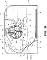
- Figure 1A is a sectional view showing a structure of an image forming apparatus 11 according to Embodiment 1 of the present invention.
- the image forming apparatus 11 utilizes an electrophotographic image forming process and is a four color-based full-color laser beam printer.
- the image forming apparatus 11 includes a main assembly 11A thereof and inside the main assembly 11A, an image forming portion for forming an image is provided.
- the image forming portion includes a photosensitive drum 3a as an image bearing member and includes a primary transfer roller 14 and the like.
- the image forming apparatus 11 includes the photosensitive drum 3a.
- a charging roller 3b as a charging means for uniformly charging the photosensitive drum 3a and an exposure device 12 as an exposure means for irradiating the photosensitive drum 3a with laser light to form a latent image on the photosensitive drum 3a are disposed.
- an one of developing cartridges, for developing the latent image formed on the photosensitive drum 3a with an associated color toner, consisting of yellow developing cartridge 5a, a magenta developing cartridge 5b, a cyan developing cartridge 5c and a black developing cartridge 5d is disposed.
- a cleaning device 3c as a cleaning means for removing residual toner on the photosensitive drum 3a is disposed.
- the photosensitive drum 3a, the charging roller 3b and the cleaning device 3c are integrally constituted and are assembled into a drum cartridge 3 which is detachably mountable to the image forming apparatus 11.
- the drum cartridge will be described.
- Each of the photosensitive drum 3a, the charging roller 3b and the cleaning device 3c may have an independent constitution or may also have an integral constitution.
- the yellow developing cartridge 5a, the magenta developing cartridge 5b, the cyan developing cartridge 5c and the black developing cartridge 5d are held by a rotary 101 which is rotatably attached to the apparatus main assembly 11A.
- Each of the yellow developing cartridge 5a, the magenta developing cartridge 5b, the cyan developing cartridge 5c and the black developing cartridge 5d may also be stationary type developing device fixed in the rotary 101.
- a developing cartridge type in which the developing cartridge is detachably mountable to the rotary 101 like the yellow developing cartridge 5a, the magenta developing cartridge 5b, the cyan developing cartridge 5c and the black developing cartridge 5d is employed.
- the rotary 101 has the same developing cartridge holding constitution with respect to all the yellow developing cartridge 5a, the magenta developing cartridge 5b, the cyan developing cartridge 5c and the black developing cartridge 5d. Therefore, in this embodiment, the constitution in which the rotary 101 holds each of the developing cartridges 5a to 5d will be described with respect to the yellow developing cartridge 5a.
- the photosensitive drum 3a is rotated in a direction indicated by an arrow A in Figure 1A .
- an intermediary transfer belt 13 is rotated in a direction indicated by an arrow C in Figure 1A .
- the surface of the photosensitive drum 3a is uniformly charged by the charging roller 3b and is irradiated with light for a yellow image by the exposure means 12 as the exposure device, so that an electrostatic latent image for yellow is formed on the photosensitive drum 3a.
- FIG 1B is a sectional view showing a driving process of the image forming apparatus 11.
- the rotary 101 is rotatable while holding the yellow developing cartridge 5a, the magenta developing cartridge 5b, the cyan developing cartridge 5c and the black developing cartridge 5d simultaneously with the formation of the electrostatic latent image described above.
- the rotary 101 is rotated about a rotary rotation shaft (rotational axis) 101a in a direction indicated by an arrow B in Figure 1A by a drive transmission mechanism provided in the apparatus main assembly 11A.
- the yellow developing cartridge 5a is disposed at a developing position in which the yellow developing cartridge 5a opposes the photosensitive drum 3a as shown in Figure 1B .
- a potential difference is set between the photosensitive drum 3a and the developing roller 2a so that a yellow developer is deposited on the latent image formed on the photosensitive drum 3a.
- the latent image formed on the photosensitive drum 3a is developed by depositing the yellow developer thereon. That is, a yellow developer image is formed on the photosensitive drum 3a.
- the yellow toner image is primary-transferred from the photosensitive drum 3a on to the intermediary transfer belt.
- the rotary 101 is further rotationally moved in the arrow B direction in Figure 1B by receiving a driving force from the drive transmission mechanism of the image forming apparatus 11. Then, the magenta developing cartridge 5b, the cyan developing cartridge 5c and the black developing cartridge 5d are successively positioned at the developing position in which the positioned developing cartridge opposes the photosensitive drum 3a.
- the formation of the electrostatic latent image, the development of the electrostatic latent image and the primary transfer are successively performed, so that four color toner images are superposed on the intermediary transfer belt 13.
- the primary transfer roller 14 described above, and an inner secondary transfer roller 15b and rollers 61 and 62 which are a conveying means for conveying a sheet as a recording material (medium) are disposed inside the intermediary transfer member 13.
- a secondary transfer roller 15 as the conveying means is disposed in non-contact with the intermediary transfer belt 13.
- a cleaning unit 16 for the intermediary transfer belt 13 is also disposed in non-contact with the intermediary transfer belt 13.
- sheets P which are a member on which the toner images are to be transferred are stacked and accommodated in a sheet feeding cassette 17 provided at a lower portion of the apparatus main assembly 11A.
- the sheets P are separated and fed one by one from the sheet feeding cassette 17 by a sheet feeding roller 18 as a feeding means, thus being fed to conveying rollers 19 as the conveying means.
- the conveying rollers 19 send the fed sheet 110 between the intermediary transfer belt 13 and the secondary transfer roller 15a.
- the secondary transfer roller 15 is in a state in which it press-contacts the intermediary transfer belt 13.
- the voltage of the opposite polarity to the toner charge polarity has been applied to the secondary transfer roller 15a, so that the above-described four color toner images superposed on the intermediary transfer belt 13 are secondary-transferred onto the surface of the conveyed sheet P.
- the sheet P on which the toner images are transferred is sent to a fixing device 20.
- the sheet P is heated and pressed, so that the toner images are fixed on the sheet P.
- an image is formed on the sheet P.
- the sheet P is discharged from the fixing device 20 to a sheet discharge portion 21 outside the image forming apparatus 11 through (sheet) discharging rollers 64a and 64b as a discharging means.
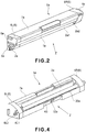
- FIG. 2 is a perspective view showing a structure (constitution) of the yellow developing cartridge 5a.
- the yellow developing cartridge 5a includes a developing container 7a capable of accommodating the developer.
- a developing roller 2a and a toner supply roller 8a which extend in a longitudinal direction of the developing container 7a.
- side members 6L and 6R are attached.
- a portion to be locked 6a engageable with a locking member 103a of the rotary 101 is formed on each of these two side members 6 (i.e., the side members 6L and 6R). For this reason, detaching of the yellow developing cartridge 5a from the rotary 101 is suppressed.
- the locking member 103a ( Figure 1A ) engages with the yellow developing cartridge 5a by a spring (not shown), thus preventing movement of the yellow developing cartridge 5a in a direction indicated by a double-pointed arrow D indicated in Figure 1A .
- a portion to be locked similar to the portion to be locked 6a is provided on each of the magenta developing cartridge 5b, the cyan developing cartridge 5c and the black developing cartridge 5d.
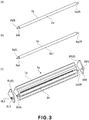
- Figure 3(a) is a perspective view showing a structure of the developing roller 2a.
- the developing roller 2a includes a rigid shaft 2a2 and a rubber roller portion 2a1 formed around the rigid shaft 2a2. That is, the rigid shaft 2a2 penetrates the rubber roller portion 2a1 in a direction along the rotational axis of the developing roller 2a, so that end portions of the rigid shaft 2a2 are projected from the rubber roller portion 2a1 to constitute projected portions 2a2L and 2a2R.
- Figure 3(b) is a perspective view showing a structure of the toner supply roller 8a.
- the toner supply roller 8a includes a rigid shaft 8a2 and a sponge roller portion 8a1 formed around the rigid shaft 8a2. That is, the rigid shaft 8a2 penetrates the sponge roller portion 8a1 in a direction along the rotational axis of the toner supply roller 8a, so that end portions of the rigid shaft 8a2 are projected from the sponge roller portion 8a1 to constitute projected portions 8a2L and 8a2R.
- Figure 3(c) is an exploded perspective view showing an inner structure (constitution) of the developing container 7a from which the side members 6L and 6R are detached.
- the side member 6L is provided with holes 6L1 and 6L2
- the side member 6R is provided with holes 6R1 and 6R2.
- the projected portion 2a2L of the developing roller 2a is inserted and into the hole 6R1, the projected portion 2a2R of the developing roller 2a is inserted, so that the developing roller 2a is rotatable relative to the developing container 7a.
- the yellow developing cartridge 5a rotatably holds the developing roller 2a and the toner supply roller 8a by the side members 6L and 6R for holding the projected portions 2a2L and 2a2R, respectively, of the developing roller 2a.
- FIG 4 is a perspective view showing the structure of the yellow developing cartridge 5a.
- a recessed portion 63 is formed at a central portion of the developing container 7a with respect to the longitudinal direction of the developing container 7a.
- the recessed portion 63 is provided with a communication hole 31a ( Figure 5 ) for establishing communication between the inside and the outside of the developing container 7a.
- a filter member 32a is fixed so as to cover the communication hole 31a from the outside of the developing container 7a. Therefore, the communication hole 31a and the filter member 32a are provided at the central portion of the developing container 7a with respect to an axial direction of the developing roller 2a.
- the communication hole 31a and the filter member 32a may only be required to be provided in the neighborhood of the central portion of the developing container 7a with respect to the longitudinal direction of the rubber roller portion 2a1. Fixation of the filter member 32a on the developing container 7a is performed by bonding the filter member 32a to the developing container 7a through welding but my fixing method can be employed.
- the developing roller 2a as a developer carrying member is disposed at an opening 52 ( Figure 5 ) of the developing container 7a and develops the electrostatic latent image, formed on the photosensitive drum 3a as the image bearing member, with the developer.
- the toner supply roller 8a as a developer supplying roller is disposed inside the developing container 7a and the supplies the developer to the developing roller 2a in contact with the developing roller 2a.
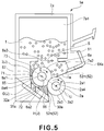
- Figure 5 is a sectional view showing the structure of the yellow developing cartridge 5a.
- the developing container 7a of the yellow developing cartridge 5a includes a first chamber 7a1 and a second chamber 7a2. Between the first chamber 7a1 and the second chamber 7a2, a through-opening 51 is provided, so that toner t inside the first chamber 7a1 can move to the second chamber 7a2.
- the through-opening 51 is sealed with a toner seal member S before the yellow developing cartridge 5a is used, so that the movement of the toner t from the first chamber 7a1 to the second chamber 7a2 is suppressed.
- the opening is uncovered by removing the seal member S by a user or the like at the time of starting the use of the cartridge, so that the toner inside the first chamber 7a1 is supplied into the second chamber 7a2.
- the second chamber 7a2 is provided with the opening 52.
- the opening 52 is defined by a portion including an upper edge portion 52m and a lower edge portion 52n.
- a developing blade 1a extending toward the surface of the developing roller 2a is attached. That is, the developing blade 1a is attached to the developing container 7a at its base en portion and contacts the developing roller 2a at its free end portion, thus regulating a layer thickness of the developer on the surface of the developing roller 2a.
- an elastic sheet member 30a extending toward the surface of the developing roller 2a is attached. That is, the elastic sheet member 30a is attached to the developing container 7a at its base end portion and contacts the developing roller 2a at its free end portion, thus preventing the developer from leaking out of the developing container 7a.
- the toner supply roller 8a is disposed in the second chamber 7a2 and inside and the opening 52.
- the developing roller 2a is disposed at the opening 52.
- the toner t is fed.
- the toner t in the first chamber 7a1 moves to the second chamber 7a2.
- the toner t is fed (supplied) to the toner supply roller 8a, and when the toner supplying roller 8a is toner t rotated about a rotational axis 8a4 in a direction indicated by an arrow E, the toner t is fed to the developing roller 2a.
- the toner t on the developing roller 2a is subjected to the development (of the electrostatic latent image formed) on the photosensitive drum 3a while being regulated by the developing blade 1a.
- the toner t left on the developing roller 2a after the development is removed by the toner supplying roller 8a. Thereafter, the toner t is fed again to the developing roller 2a by the toner supplying roller 8a.
- a voltage is applied from the image forming apparatus 11 in order to provide a potential difference between the developing roller 2a and the photosensitive drum 3a. Also to the toner supply roller 8a, a voltage is applied from the image forming apparatus 11.
- the elastic sheet member 30a functions as the toner seal member for preventing the toner t inside the second chamber 7a2 from leaking out from between the lower edge portion 52n of the opening 52 and the rubber roller portion 2a1 of the developing roller 2a.
- the base end of the elastic sheet member 30a is fixed on the developing container 7a along the longitudinal direction. Further, the free end of the elastic sheet member 30a contacts the entire developing area of the rubber roller portion 2a1 along the longitudinal direction.
- the elastic sheet member 30a contacts the developing roller 2a with a small pressure. This is because when the contact pressure of the elastic sheet member 30a with respect to the developing roller 2a is large, the toner layer on the developing roller 2a is disturbed and thus there is a possibility of an occurrence of image defect.
- the yellow developing cartridge 5a is urged toward the photosensitive drum 3a together with the rotary 103 which holds the yellow developing cartridge 5a.
- the developing roller 2a of the yellow developing cartridge 5a can contact the photosensitive drum 3a with a predetermined pressure.
- the developing container 7a is provided with the communication hole 31a in a wall of the second chamber 7a2 so as to establish communication between the inside and the outside of the developing container 7a.
- the filter member 32a is attached to the developing container 7a so as to externally cover the communication hole 31a.
- the filter member 32a covers the communication hole 31a, thus preventing passage of the developer while permitting passage of the air.
- the surface of the sponge roller portion 8a1 of the toner supply roller 8a constitutes a roller surface 8a3, and an inner wall surface of the developing container 7a which is formed coaxially with a rotation center 8a4 of the toner supply roller 8a along the (circumferential) roller surface 8a3 of the toner supply roller 8a constitutes a coaxial surface (curved surface portion) 65.
- a phantom plane which can be drawn from a lowermost-stream position of the coaxial surface (curved surface portion) 65, with respect to the toner supply roller rotational direction, to the roller surface 8a3 constitutes a first phantom plane 71.
- a phantom plane which can be drawn from an uppermost-stream position of the coaxial surface 65, with respect to the toner supply roller rotation direction, to the roller surface 8a3 constitutes a second phantom plane 72.
- a space enclosed by the toner supply roller surface 8a3, the coaxial surface 65, the first phantom plane 71 are the second phantom plane 72 constitutes a phantom space G.
- the first phantom plane 71, the second phantom plane 72 and the phantom space G are not present actually but are the planes and the space which are used for showing the position or the area inside the developing container 7a for convenience's sake. This is true for an enclosed space J, a third phantom plane 73, a phantom plane H, and a phantom plane I described later.
- the surface of the rubber roller portion 2a1 of the developing roller 2a constitutes a roller surface 2a3
- the surface of the developing container 7a formed closer to the elastic sheet member 30a than the phantom space G constitutes an inner wall surface 66.
- a distance between the inner wall surface 66 and the roller surface 8a3 is larger than a distance between the curved surface portion 65 and the roller surface 8a3.
- a space enclosed by the roller surfaces 2a3 and 8a3, the phantom plane 72, the inner wall surface 66 and the elastic sheet member 30a constitutes the phantom space H.
- the surface of the developing container 7a formed farther from the elastic sheet member 30a than the phantom space G constitutes an inner wall surface 67.
- a distance between the inner wall surface 67 and the roller surface 8a3 is larger than a distance between the curved surface portion 65 and the roller surface 8a3.
- a plane including a rotational axis 8a4 of the toner supply roller 8a and a rotational axis 2a4 of the developing roller 2 constitutes a plane U.
- a phantom plane which is provided in this plane U so as to extend from the roller surface 8a3 of the toner supply roller 8a to the inner wall of the developing container 7a constitutes the third phantom plane 73.
- a space enclosed by the roller surface 8a3, the first phantom plane 71, the inner wall surface 67 and the third phantom plane 73 constitutes the phantom space I.
- a space enclosed by the toner supply roller surface 8a3, the second phantom plane 72, the inner wall surface 66, the elastic sheet member 30a and the developing roller surface 2a3 constitutes the phantom space H.
- the communication hole 31a described above establishes communication between an area including the phantom spaces G, H and I, and an external area of the developing container 7a.
- the communication hole 31a faces the enclosed space J including the phantom spaces G, H and I and opens to the inside of the developing container 7a. That is, the communication hole 31a is provided so as to be connected to the enclosed space J. For that reason, the air in the enclosed space J can pass through the communication hole 31a. Further, the air can move to the outside of the developing container 7a.
- the enclosed space J enclosed (defined) by the developing container 7a, the developing roller 2a, the toner supply roller 8a and the elastic sheet member 30a is narrow, so that a change in pressure occurs due to bending of the developing roller 2a and the toner supply roller 8a.
- the pressure change is large in the neighborhood of longitudinal central portion at which the developing roller 2a and the toner supply roller 8a are liable to be bent largely, so that there is a possibility of an occurrence of the leakage of the toner from between the developing roller 2a and the elastic sheet member 30a contacting the developing roller 2a with the small pressure.
- the present invention by employing such a constitution that the communication hole 31a is directly connected to a small space when the developing container 7a is divided into the small space and a large space by the plane U described above, the toner leakage is effectively suppressed.
- the small space is the enclosed space J
- the large space is a space in the developing container 7a except the enclosed space J (the space located above the plane U in Figure 5 ). Therefore, the inner wall of the developing container 7a constituting the enclosed space J is the inner wall constituting the small space when the developing container 7a is divided into the small space and the large space.
- this inner wall corresponds to the inner wall surfaces 66, 65 and 67.
- the communication hole 31a is connected to the phantom space G which is a narrowest area of the small space (the enclosed space). That is, the communication hole 31a is configured to be connected to the curved surface portion 65 of the container inner wall.
- the toner t toner particles having an average particle size of 6 - 8 ⁇ m are used.
- the filter member 32 a member having a hole diameter of 5 ⁇ m is used in a superposed state. For this reason, the filter member 32 prevents the leakage of the toner t while permitting the passage of the air.
- the hole diameter of the filter member 32 may preferably be smaller than the toner particle size.
- the toner leakage from the filter member 32 can be prevented.
- Figure 6(a) shows an arrangement relationship between the developing roller 2a and the toner supply roller 8a in a normal use state, as seen from a Z direction in Figure 4 .
- Figure 6(b) is a sectional view taken along L-L line indicated in Figure 6(a) .
- the developing roller 2a and the toner supply roller 8a are in a state in which these rollers are extended in a straight line.
- the filter member 32a is located at the central portion of the developing container 7a corresponding to a substantially central portion of the sponge roller portion 8a1 of the toner supply roller 8a and is located at a portion corresponding to a lower end portion of the sponge roller portion 8a1.
- the volume of the narrow area is kept at that in the normal (use) state. Further, the developing roller 2a is in a state in which the developing roller 2a partly deforms the sponge roller portion 8a1 of the toner supply roller 8a.
- Figure 7(a) shows an arrangement relationship between the developing roller 2a and the toner supply roller 8a in the case where the yellow developing cartridge 5a is dropped on a floor and is a sectional view, as seen from the Z direction in Figure 4 .
- Figure 7(b) is a sectional view taken along M-M line indicated in Figure 7(a) .
- the developing roller 2a and the toner supply roller 8a can be bent in a direction in which the central portions of the developing roller 2a and the toner supply roller 8a with respect to the longitudinal direction are spaced from each other.
- Figure 7(x) shows an arrangement relationship between the developing roller 2a and the toner supply roller 8a in the case where the yellow developing cartridge 5a is dropped on a floor and is a sectional view, as seen from the Z direction in Figure 4 .
- Figure 7(d) is a sectional view taken along N-N line indicated in Figure 7(c) .
- the developing roller 2a and the toner supply roller 8a can be bent in a direction in which the central portions of the developing roller 2a and the toner supply roller 8a with respect to the longitudinal direction approach each other.
- the drum cartridge 3 at least including the photosensitive drum 3a and the charging roller 3b and the developing cartridge 5 at least including the developing roller 2a have independent constitutions, and each of the cartridges is detachably mountable to the apparatus main assembly 11A.
- the form of the cartridges is not limited to those described above but may also be that of a process cartridge having a constitution in which the drum cartridge 3 and the developing cartridge 5 are integrally assembled.
- the yellow developing cartridge 5a is prepared by integrally assembling the developing roller 2a for developing the electrostatic latent image formed on the photosensitive drum 3a, the developing container 7a for accommodating the developer, and the developing blade 1a into a cartridge, which is detachably mountable to the apparatus main assembly 11A.
- the process cartridge is prepared by integrally assembling the photosensitive drum 3a, the developing roller 2a for developing the electrostatic latent image formed on the photosensitive drum 3a, and the developing container 7a for accommodating the developer into a cartridge, which is detachably mountable to the apparatus main assembly 11A.
- the pressure change occurs in the neighborhood of the elastic sheet member 30a.
- the communication hole 31a is provided at a portion enclosed by the developing container 7a, the developing roller 2a, the toner supply roller 8a and the elastic sheet member 30a and the outside of the portion is covered with the filter member 32a by bonding.
- the toner was leaked in some instances by abrupt movement of the air inside the developing container 7a or by bending of the developing roller 2a or the toner supply roller 8a.
- the space enclosed by the developing container 7a, the developing roller 2a, the toner supply roller 8a and the elastic sheet member 30a is narrow, and the developing roller 2a and the toner supply roller 8a are bent to cause the change in pressure.
- the change in pressure is large.
- the filter member 32a which permits the passage of the air and prevents the passage of the toner t is provided.
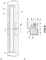
- FIG 8 is a sectional view showing a structure of a yellow developing cartridge 105a according to Embodiment 2.
- the yellow developing cartridge 105a portions or members having the same constitutions and effects as those for the yellow developing cartridge 5a in Embodiment 1 are represented by the same reference numerals or symbols and will be appropriately omitted from description.
- the yellow developing cartridge 105a is applicable to the image forming apparatus similar to that in Embodiment 1, so that the description of the image forming apparatus will be omitted.
- a difference of the yellow developing cartridge 105a in Embodiment 2 from the yellow developing cartridge 5a in Embodiment 1 is that a path of the creation of a communication hole 131a is different from that of the communication hole 31a.
- the constitution of the yellow developing cartridge 105a will be described but the magenta developing cartridge, the cyan developing cartridge and the back developing cartridge have the same constitution.
- the communication hole 131a is provided in the wall of the second chamber 7a2 inside the enclosed space J similarly as in Embodiment 1 but is provided at a position which is farther from the elastic sheet member 30a than the phantom space G, i.e., is open to the inside of the developing container 7a in the phantom space I. Also in this embodiment, the communication hole 131a is configured to be connected to the enclosed space J which is the narrow space in which the pressure change is liable to become large, so that the toner leakage can be suppressed.
- Embodiments 1 and 2 in the case where the developing device, the developing cartridge, the process cartridge and the image forming apparatus are subjected to the impact, the pressure fluctuation due to the bending of the developing roller 2a and the toner supply roller 8a can be reduced efficiently. As a result, in the case where the toner seal member S is removed, it is possible to reduce the possibility of the leakage of the toner t from the gap between the elastic sheet member 30a and the developing roller 2a.
- the toner in the enclosed space J is most liable to be leaked out from between the elastic sheet member 30a and the developing roller 2a.
- the communication holes 31a and 131a are connected to the enclosed space J and are open to the inside of the developing container 7a, the leakage of the toner t in the enclosed space J is suppressed very effectively.
- the constitution of the developing cartridges 5a to 5d is not limited to those in Embodiments 1 and 2 but may also be applied to the developing device fixed in the apparatus main assembly 11A and to the process cartridge using the developing cartridge and the drum cartridge in combination.
- a developing device as defined by claim 1 includes among other elements a developing container capable of accommodating a developer; a developing roller disposed at an opening of the developing container; a developer supplying roller, disposed inside the developing container; a sheet member which is attached to the developing container at its base end portion and which contacts the developing roller at its free end portion; a communication hole provided in a wall of the developing container; and a filter member for covering the communication hole so as to prevent passage of the developer therethrough while permitting passage of air therethrough.
- the communication hole is provided so as to be connected to an enclosed space defined by an inner wall of the developing container defining a smaller one of spaces provided by dividing the developing container by a plane including a rotation axis of said developer supplying roller and a rotational axis of said developing roller, a phantom plane which is included in the plane and extends from a surface of the developer supplying roller to the inner wall of the developer container, the sheet member, a surface of the developing roller, and a surface of the developer supplying roller.
Landscapes
- Physics & Mathematics (AREA)
- General Physics & Mathematics (AREA)
- Dry Development In Electrophotography (AREA)
Applications Claiming Priority (2)
| Application Number | Priority Date | Filing Date | Title |
|---|---|---|---|
| JP2009250150 | 2009-10-30 | ||
| JP2010205557A JP5751779B2 (ja) | 2009-10-30 | 2010-09-14 | 現像装置、現像カートリッジ、プロセスカートリッジ、及び、画像形成装置 |
Publications (3)
| Publication Number | Publication Date |
|---|---|
| EP2317397A2 EP2317397A2 (en) | 2011-05-04 |
| EP2317397A3 EP2317397A3 (en) | 2017-11-01 |
| EP2317397B1 true EP2317397B1 (en) | 2020-12-09 |
Family
ID=43479496
Family Applications (1)
| Application Number | Title | Priority Date | Filing Date |
|---|---|---|---|
| EP10188646.3A Active EP2317397B1 (en) | 2009-10-30 | 2010-10-25 | Developing device, developing cartridge, process cartridge and image forming apparatus |
Country Status (5)
| Country | Link |
|---|---|
| US (1) | US8483589B2 (zh) |
| EP (1) | EP2317397B1 (zh) |
| JP (1) | JP5751779B2 (zh) |
| KR (1) | KR101324386B1 (zh) |
| CN (1) | CN102053529B (zh) |
Families Citing this family (13)
| Publication number | Priority date | Publication date | Assignee | Title |
|---|---|---|---|---|
| EP2333620A1 (en) | 2008-09-01 | 2011-06-15 | Canon Kabushiki Kaisha | Developing cartridge, process cartridge, and electrophotographic image forming apparatus |
| JP4954261B2 (ja) * | 2009-10-30 | 2012-06-13 | キヤノン株式会社 | 電子写真画像形成装置 |
| JP6128823B2 (ja) * | 2011-12-21 | 2017-05-17 | キヤノン株式会社 | 現像容器、その製造方法、それを用いる現像装置及び画像形成装置 |
| JP6108728B2 (ja) | 2012-08-31 | 2017-04-05 | キヤノン株式会社 | 梱包材及びカートリッジ |
| JP6207140B2 (ja) * | 2012-09-27 | 2017-10-04 | キヤノン株式会社 | カートリッジ及びカートリッジの製造方法 |
| CN103869661B (zh) * | 2012-12-17 | 2018-09-11 | 株式会社理光 | 显影装置以及图像形成装置 |
| US10620563B2 (en) | 2016-10-31 | 2020-04-14 | Canon Kabushiki Kaisha | Developer container, process cartridge, and image forming apparatus |
| US10866539B2 (en) | 2016-11-09 | 2020-12-15 | Canon Kabushiki Kaisha | Unit having a developer conveying member and a filter for a chamber |
| SG10202111783UA (en) | 2017-06-15 | 2021-12-30 | Canon Kk | Cartridge and electrophotographic image forming apparatus |
| US10534291B2 (en) * | 2017-10-26 | 2020-01-14 | Hewlett-Packard Development Company, L.P. | Image forming system with developer retainer |
| JP7080678B2 (ja) | 2018-03-13 | 2022-06-06 | キヤノン株式会社 | カートリッジ |
| JP7275514B2 (ja) | 2018-09-27 | 2023-05-18 | ブラザー工業株式会社 | トナーカートリッジ |
| JP7187305B2 (ja) | 2018-12-28 | 2022-12-12 | キヤノン株式会社 | プロセスカートリッジ及び現像カートリッジ |
Family Cites Families (85)
| Publication number | Priority date | Publication date | Assignee | Title |
|---|---|---|---|---|
| US2101005A (en) * | 1930-03-20 | 1937-11-30 | Hemphill Co | Knitting machine |
| JPS59182479A (ja) * | 1983-04-01 | 1984-10-17 | Fuji Xerox Co Ltd | 電子写真複写機等におけるトナ−クラウド防止装置 |
| JPS6012565A (ja) * | 1983-07-04 | 1985-01-22 | Matsushita Electric Ind Co Ltd | 現像装置 |
| JPH03289683A (ja) * | 1990-04-06 | 1991-12-19 | Matsushita Electric Ind Co Ltd | 現像器 |
| JPH04298772A (ja) * | 1991-01-23 | 1992-10-22 | Canon Inc | 現像装置 |
| US5331373A (en) | 1992-03-13 | 1994-07-19 | Canon Kabushiki Kaisha | Image forming apparatus, process cartridge mountable within it and method for attaching photosensitive drum to process cartridge |
| JP3352155B2 (ja) | 1992-06-30 | 2002-12-03 | キヤノン株式会社 | プロセスカートリッジ及び画像形成装置 |
| JP3094255B2 (ja) * | 1992-07-08 | 2000-10-03 | コニカ株式会社 | 現像器 |
| JPH06194947A (ja) * | 1992-12-25 | 1994-07-15 | Canon Inc | 現像装置 |
| EP0625729B1 (en) | 1993-05-20 | 1998-11-04 | Canon Kabushiki Kaisha | A process cartridge |
| JP3869868B2 (ja) | 1994-04-27 | 2007-01-17 | キヤノン株式会社 | プロセスカートリッジ及び画像形成装置 |
| JP3337859B2 (ja) | 1994-04-26 | 2002-10-28 | キヤノン株式会社 | プロセスカートリッジ及び画像形成装置 |
| AU3426895A (en) | 1994-10-17 | 1996-05-02 | Canon Kabushiki Kaisha | Toner container, toner container assembling method, process cartridge, and electrophotographic image forming apparatus |
| JP3315560B2 (ja) | 1995-06-13 | 2002-08-19 | キヤノン株式会社 | プロセスカートリッジ及び電子写真画像形成装置及び電子写真感光体ドラムの取り付け方法 |
| JP3372719B2 (ja) | 1995-07-11 | 2003-02-04 | キヤノン株式会社 | プロセスカートリッジ及び画像形成装置 |
| JP3402872B2 (ja) | 1995-08-25 | 2003-05-06 | キヤノン株式会社 | プロセスカートリッジの再生方法及びプロセスカートリッジ |
| JPH0962079A (ja) | 1995-08-25 | 1997-03-07 | Canon Inc | プロセスカートリッジのトナー再充填方法及びプロセスカートリッジ |
| JP3363751B2 (ja) | 1996-08-29 | 2003-01-08 | キヤノン株式会社 | プロセスカートリッジ及び電子写真画像形成装置 |
| JP3332818B2 (ja) | 1996-08-29 | 2002-10-07 | キヤノン株式会社 | プロセスカートリッジ及び電子写真画像形成装置及び接続端子の接続方法 |
| JP3342362B2 (ja) | 1996-09-20 | 2002-11-05 | キヤノン株式会社 | プロセスカートリッジ及び電子写真画像形成装置 |
| JPH10222041A (ja) | 1996-12-03 | 1998-08-21 | Canon Inc | プロセスカートリッジ及び電子写真画像形成装置 |
| JP3363727B2 (ja) | 1996-12-12 | 2003-01-08 | キヤノン株式会社 | プロセスカートリッジ及び電子写真画像形成装置及びプロセスカートリッジの組立方法及び廃トナー容器の組立方法 |
| JP3745111B2 (ja) | 1997-03-18 | 2006-02-15 | キヤノン株式会社 | 結合部材、プロセスカートリッジ、及び、プロセスカートリッジの組立方法 |
| JP3332813B2 (ja) | 1997-08-01 | 2002-10-07 | キヤノン株式会社 | プロセスカートリッジ及び電子写真画像形成装置 |
| JPH11249495A (ja) | 1998-03-03 | 1999-09-17 | Canon Inc | アース部材、円筒部材、プロセスカートリッジ、電子写真画像形成装置 |
| JPH11249494A (ja) | 1998-03-03 | 1999-09-17 | Canon Inc | ドラムフランジ、円筒部材、プロセスカートリッジ、電子写真画像形成装置 |
| JPH11272076A (ja) * | 1998-03-20 | 1999-10-08 | Ricoh Co Ltd | 現像装置 |
| JPH11305545A (ja) * | 1998-04-17 | 1999-11-05 | Canon Inc | 現像装置、プロセスカートリッジ及び画像形成装置 |
| JP3768681B2 (ja) | 1998-05-26 | 2006-04-19 | キヤノン株式会社 | トナー容器及びプロセスカートリッジ |
| JP2000075638A (ja) * | 1998-08-31 | 2000-03-14 | Canon Inc | 現像装置、現像カートリッジ及び画像形成装置 |
| JP2000122418A (ja) * | 1998-10-12 | 2000-04-28 | Minolta Co Ltd | 現像装置 |
| JP3673658B2 (ja) | 1998-10-28 | 2005-07-20 | キヤノン株式会社 | プロセスカートリッジ及び電子写真画像形成装置 |
| JP3697090B2 (ja) | 1998-10-26 | 2005-09-21 | キヤノン株式会社 | 電子写真画像形成装置 |
| JP3684092B2 (ja) | 1998-10-26 | 2005-08-17 | キヤノン株式会社 | 電子写真画像形成装置 |
| JP2000131940A (ja) | 1998-10-27 | 2000-05-12 | Canon Inc | 現像装置、現像カ−トリッジおよび画像形成装置 |
| JP3320399B2 (ja) | 1999-05-20 | 2002-09-03 | キヤノン株式会社 | プロセスカートリッジ及びプロセスカートリッジの組み立て方法及び電子写真画像形成装置 |
| JP3748506B2 (ja) | 1999-05-20 | 2006-02-22 | キヤノン株式会社 | プロセスカートリッジ及びプロセスカートリッジの組立方法 |
| JP3320398B2 (ja) | 1999-05-20 | 2002-09-03 | キヤノン株式会社 | プロセスカートリッジおよび電子写真画像形成装置 |
| US6549736B2 (en) | 2000-01-19 | 2003-04-15 | Canon Kabushiki Kaisha | Process cartridge, engaging member therefor and method for mounting developing roller and magnet |
| DE60144502D1 (de) | 2000-06-09 | 2011-06-09 | Canon Kk | Entwicklungsgerät, Arbeitseinheit und flexibele Dichtung |
| JP3658315B2 (ja) | 2000-12-19 | 2005-06-08 | キヤノン株式会社 | プロセスカートリッジ及び電子写真画像形成装置 |
| JP4677093B2 (ja) | 2000-12-25 | 2011-04-27 | キヤノン株式会社 | プロセスカートリッジ |
| JP3542569B2 (ja) | 2001-04-27 | 2004-07-14 | キヤノン株式会社 | プロセスカートリッジの再生産方法 |
| JP3840063B2 (ja) | 2001-04-27 | 2006-11-01 | キヤノン株式会社 | プロセスカートリッジ |
| JP3564080B2 (ja) | 2001-04-27 | 2004-09-08 | キヤノン株式会社 | プロセスカートリッジの再生産方法 |
| US6915094B2 (en) * | 2002-01-16 | 2005-07-05 | Canon Kabushiki Kaisha | Composition for accessing a memory in image formation apparatus and method for accessing a memory in image formation apparatus |
| JP2003270939A (ja) | 2002-03-18 | 2003-09-25 | Seiko Epson Corp | 現像装置、画像形成装置、及びコンピュータシステム |
| JP3919678B2 (ja) * | 2003-02-20 | 2007-05-30 | 株式会社リコー | 現像装置、画像形成装置及びプロセスカートリッジ |
| JP4110143B2 (ja) | 2004-01-30 | 2008-07-02 | キヤノン株式会社 | 電子写真画像形成装置、電子写真画像形成装置に着脱可能なユニット及びプロセスカートリッジ |
| US7164875B2 (en) | 2004-03-30 | 2007-01-16 | Canon Kabushiki Kaisha | Electrophotographic image forming apparatus having a plurality of mounting portions for detachably mounting a plurality process cartridges |
| JP3970274B2 (ja) | 2004-03-31 | 2007-09-05 | キヤノン株式会社 | プロセスカートリッジ及び電子写真画像形成装置 |
| JP4110128B2 (ja) | 2004-04-26 | 2008-07-02 | キヤノン株式会社 | プロセスカートリッジ、電子写真画像形成装置及び軸受部材 |
| JP2005316192A (ja) | 2004-04-28 | 2005-11-10 | Canon Inc | 電子写真画像形成装置 |
| JP4631318B2 (ja) * | 2004-06-09 | 2011-02-16 | 富士ゼロックス株式会社 | 画像形成装置および像担持体ユニット |
| US20060008289A1 (en) | 2004-07-06 | 2006-01-12 | Canon Kabushiki Kaisha | Electrophotographic image forming apparatus and process cartridge |
| JP4617122B2 (ja) | 2004-09-08 | 2011-01-19 | キヤノン株式会社 | 現像剤搬送部材、現像装置、および、プロセスカートリッジ |
| JP4886182B2 (ja) | 2004-09-27 | 2012-02-29 | キヤノン株式会社 | カートリッジ、プロセスカートリッジ、及び、電子写真画像形成装置 |
| JP3950882B2 (ja) | 2004-10-06 | 2007-08-01 | キヤノン株式会社 | 電子写真画像形成装置 |
| JP3950883B2 (ja) | 2004-10-06 | 2007-08-01 | キヤノン株式会社 | 電子写真画像形成装置 |
| JP2006250973A (ja) | 2005-03-08 | 2006-09-21 | Fuji Xerox Co Ltd | 現像装置及びこれを用いた画像形成装置 |
| JP4337759B2 (ja) * | 2005-03-28 | 2009-09-30 | コニカミノルタビジネステクノロジーズ株式会社 | 現像装置及び画像形成装置 |
| JP4794892B2 (ja) | 2005-04-11 | 2011-10-19 | キヤノン株式会社 | プロセスカートリッジ及び電子写真画像形成装置 |
| JP2007072107A (ja) * | 2005-09-06 | 2007-03-22 | Canon Inc | カートリッジおよびこれを用いた画像形成装置 |
| JP4695542B2 (ja) | 2005-10-25 | 2011-06-08 | 株式会社リコー | 現像装置、プロセスカートリッジ及び画像形成装置 |
| JP4646802B2 (ja) * | 2005-12-28 | 2011-03-09 | シャープ株式会社 | 現像装置及び画像形成装置 |
| JP4498407B2 (ja) | 2006-12-22 | 2010-07-07 | キヤノン株式会社 | プロセスカートリッジ、電子写真画像形成装置、及び、電子写真感光体ドラムユニット |
| JP4948382B2 (ja) | 2006-12-22 | 2012-06-06 | キヤノン株式会社 | 感光ドラム取り付け用カップリング部材 |
| JP4535077B2 (ja) * | 2007-03-15 | 2010-09-01 | コニカミノルタビジネステクノロジーズ株式会社 | 現像装置および画像形成装置 |
| JP5311854B2 (ja) * | 2007-03-23 | 2013-10-09 | キヤノン株式会社 | 電子写真画像形成装置、現像装置、及び、カップリング部材 |
| US7711287B2 (en) | 2007-05-15 | 2010-05-04 | Canon Kabushiki Kaisha | Cartridge and electrophotographic image forming apparatus |
| JP4262294B2 (ja) * | 2007-05-15 | 2009-05-13 | キヤノン株式会社 | カラー電子写真画像形成装置 |
| JP2009020286A (ja) * | 2007-07-11 | 2009-01-29 | Canon Inc | 現像装置及びプロセスカートリッジ |
| US7725058B2 (en) * | 2007-09-14 | 2010-05-25 | Samsung Electronics Co., Ltd. | Developing unit and image forming apparatus having the same |
| JP5327573B2 (ja) * | 2007-10-31 | 2013-10-30 | 株式会社リコー | 現像装置、プロセスユニット及び画像形成装置 |
| JP2009204845A (ja) * | 2008-02-27 | 2009-09-10 | Kyocera Mita Corp | 画像形成装置 |
| JP5463008B2 (ja) * | 2008-03-31 | 2014-04-09 | 京セラドキュメントソリューションズ株式会社 | 現像装置及びそれを備えた画像形成装置 |
| JP5335543B2 (ja) * | 2008-06-20 | 2013-11-06 | キヤノン株式会社 | 画像形成装置 |
| JP5306050B2 (ja) | 2008-06-20 | 2013-10-02 | キヤノン株式会社 | カートリッジ、カップリング部材の取り付け方法、及び、カップリング部材の取り外し方法 |
| JP5371627B2 (ja) | 2008-08-27 | 2013-12-18 | キヤノン株式会社 | 現像装置、現像カートリッジ、及び、電子写真画像形成装置 |
| JP5386129B2 (ja) * | 2008-08-29 | 2014-01-15 | 京セラドキュメントソリューションズ株式会社 | 現像装置および画像形成装置 |
| JP5419584B2 (ja) | 2008-09-01 | 2014-02-19 | キヤノン株式会社 | カートリッジ及び電子写真画像形成装置 |
| JP5335329B2 (ja) | 2008-09-01 | 2013-11-06 | キヤノン株式会社 | 画像形成装置 |
| JP4663801B2 (ja) | 2008-09-01 | 2011-04-06 | キヤノン株式会社 | プロセスカートリッジ及び画像形成装置 |
| JP5147607B2 (ja) | 2008-09-01 | 2013-02-20 | キヤノン株式会社 | 画像形成装置 |
| JP5305233B2 (ja) * | 2009-02-24 | 2013-10-02 | 株式会社リコー | 現像装置、プロセスカートリッジ、及び、画像形成装置 |
-
2010
- 2010-09-14 JP JP2010205557A patent/JP5751779B2/ja not_active Expired - Fee Related
- 2010-10-18 US US12/906,441 patent/US8483589B2/en active Active
- 2010-10-25 EP EP10188646.3A patent/EP2317397B1/en active Active
- 2010-10-29 CN CN2010105297675A patent/CN102053529B/zh active Active
- 2010-10-29 KR KR1020100106800A patent/KR101324386B1/ko active IP Right Grant
Non-Patent Citations (1)
| Title |
|---|
| None * |
Also Published As
| Publication number | Publication date |
|---|---|
| CN102053529A (zh) | 2011-05-11 |
| EP2317397A2 (en) | 2011-05-04 |
| CN102053529B (zh) | 2013-07-03 |
| US8483589B2 (en) | 2013-07-09 |
| JP5751779B2 (ja) | 2015-07-22 |
| EP2317397A3 (en) | 2017-11-01 |
| KR20110048006A (ko) | 2011-05-09 |
| KR101324386B1 (ko) | 2013-11-01 |
| JP2011118357A (ja) | 2011-06-16 |
| US20110103827A1 (en) | 2011-05-05 |
Similar Documents
| Publication | Publication Date | Title |
|---|---|---|
| EP2317397B1 (en) | Developing device, developing cartridge, process cartridge and image forming apparatus | |
| US8401441B2 (en) | Cartridge and electrophotographic image forming apparatus | |
| JP4663802B2 (ja) | カバー部材及びカートリッジ | |
| EP3258321B1 (en) | Detachable toner cartridge and image forming apparatus including the same | |
| US8687994B2 (en) | Cartridge with roller shaft having an exposed electroconductive portion | |
| US8270879B2 (en) | Electrophotographic image forming apparatus | |
| EP1170641A2 (en) | Developing cartridge, process cartridge and electrophotographic image forming apparatus | |
| US7983589B2 (en) | Developing apparatus, process cartridge, and image forming apparatus | |
| US8787803B2 (en) | Developing device, image forming unit and image forming apparatus | |
| US8050591B2 (en) | Powder developer holding apparatus, developing apparatus, and image forming apparatus | |
| US20110103823A1 (en) | Developing cartridge and process cartridge | |
| JP4157809B2 (ja) | 剤供給装置及び画像形成装置 | |
| US8798501B2 (en) | Cover member and cartridge | |
| US6498914B2 (en) | Seal part and developing device having the same | |
| US10571858B2 (en) | Image forming apparatus and configuration of cartridge unit | |
| US20130121721A1 (en) | Developer conveyance apparatus developing apparatus and process cartridge | |
| US9507293B2 (en) | Image forming apparatus and image carrier unit | |
| JP5306146B2 (ja) | 現像カートリッジ | |
| JP5240562B2 (ja) | 現像装置、プロセスカートリッジ及び画像形成装置 | |
| US7647010B2 (en) | Toner cartridge and image forming apparatus | |
| US8626031B2 (en) | Image forming apparatus | |
| JP4850879B2 (ja) | 現像カートリッジ及びプロセスカートリッジ |
Legal Events
| Date | Code | Title | Description |
|---|---|---|---|
| PUAI | Public reference made under article 153(3) epc to a published international application that has entered the european phase |
Free format text: ORIGINAL CODE: 0009012 |
|
| AK | Designated contracting states |
Kind code of ref document: A2 Designated state(s): AL AT BE BG CH CY CZ DE DK EE ES FI FR GB GR HR HU IE IS IT LI LT LU LV MC MK MT NL NO PL PT RO RS SE SI SK SM TR |
|
| AX | Request for extension of the european patent |
Extension state: BA ME |
|
| PUAL | Search report despatched |
Free format text: ORIGINAL CODE: 0009013 |
|
| AK | Designated contracting states |
Kind code of ref document: A3 Designated state(s): AL AT BE BG CH CY CZ DE DK EE ES FI FR GB GR HR HU IE IS IT LI LT LU LV MC MK MT NL NO PL PT RO RS SE SI SK SM TR |
|
| AX | Request for extension of the european patent |
Extension state: BA ME |
|
| RIC1 | Information provided on ipc code assigned before grant |
Ipc: G03G 15/08 20060101AFI20170928BHEP |
|
| STAA | Information on the status of an ep patent application or granted ep patent |
Free format text: STATUS: REQUEST FOR EXAMINATION WAS MADE |
|
| 17P | Request for examination filed |
Effective date: 20180502 |
|
| RBV | Designated contracting states (corrected) |
Designated state(s): AL AT BE BG CH CY CZ DE DK EE ES FI FR GB GR HR HU IE IS IT LI LT LU LV MC MK MT NL NO PL PT RO RS SE SI SK SM TR |
|
| GRAP | Despatch of communication of intention to grant a patent |
Free format text: ORIGINAL CODE: EPIDOSNIGR1 |
|
| STAA | Information on the status of an ep patent application or granted ep patent |
Free format text: STATUS: GRANT OF PATENT IS INTENDED |
|
| INTG | Intention to grant announced |
Effective date: 20200709 |
|
| RIN1 | Information on inventor provided before grant (corrected) |
Inventor name: UNEME, TETSUSHI Inventor name: MIYABE, SHIGEO Inventor name: NUMATA, TETSUYA |
|
| GRAS | Grant fee paid |
Free format text: ORIGINAL CODE: EPIDOSNIGR3 |
|
| GRAA | (expected) grant |
Free format text: ORIGINAL CODE: 0009210 |
|
| STAA | Information on the status of an ep patent application or granted ep patent |
Free format text: STATUS: THE PATENT HAS BEEN GRANTED |
|
| AK | Designated contracting states |
Kind code of ref document: B1 Designated state(s): AL AT BE BG CH CY CZ DE DK EE ES FI FR GB GR HR HU IE IS IT LI LT LU LV MC MK MT NL NO PL PT RO RS SE SI SK SM TR |
|
| REG | Reference to a national code |
Ref country code: GB Ref legal event code: FG4D |
|
| REG | Reference to a national code |
Ref country code: AT Ref legal event code: REF Ref document number: 1344046 Country of ref document: AT Kind code of ref document: T Effective date: 20201215 Ref country code: CH Ref legal event code: EP |
|
| REG | Reference to a national code |
Ref country code: DE Ref legal event code: R096 Ref document number: 602010066100 Country of ref document: DE |
|
| REG | Reference to a national code |
Ref country code: IE Ref legal event code: FG4D |
|
| PG25 | Lapsed in a contracting state [announced via postgrant information from national office to epo] |
Ref country code: GR Free format text: LAPSE BECAUSE OF FAILURE TO SUBMIT A TRANSLATION OF THE DESCRIPTION OR TO PAY THE FEE WITHIN THE PRESCRIBED TIME-LIMIT Effective date: 20210310 Ref country code: FI Free format text: LAPSE BECAUSE OF FAILURE TO SUBMIT A TRANSLATION OF THE DESCRIPTION OR TO PAY THE FEE WITHIN THE PRESCRIBED TIME-LIMIT Effective date: 20201209 Ref country code: RS Free format text: LAPSE BECAUSE OF FAILURE TO SUBMIT A TRANSLATION OF THE DESCRIPTION OR TO PAY THE FEE WITHIN THE PRESCRIBED TIME-LIMIT Effective date: 20201209 Ref country code: NO Free format text: LAPSE BECAUSE OF FAILURE TO SUBMIT A TRANSLATION OF THE DESCRIPTION OR TO PAY THE FEE WITHIN THE PRESCRIBED TIME-LIMIT Effective date: 20210309 |
|
| REG | Reference to a national code |
Ref country code: AT Ref legal event code: MK05 Ref document number: 1344046 Country of ref document: AT Kind code of ref document: T Effective date: 20201209 |
|
| PG25 | Lapsed in a contracting state [announced via postgrant information from national office to epo] |
Ref country code: LV Free format text: LAPSE BECAUSE OF FAILURE TO SUBMIT A TRANSLATION OF THE DESCRIPTION OR TO PAY THE FEE WITHIN THE PRESCRIBED TIME-LIMIT Effective date: 20201209 Ref country code: SE Free format text: LAPSE BECAUSE OF FAILURE TO SUBMIT A TRANSLATION OF THE DESCRIPTION OR TO PAY THE FEE WITHIN THE PRESCRIBED TIME-LIMIT Effective date: 20201209 Ref country code: BG Free format text: LAPSE BECAUSE OF FAILURE TO SUBMIT A TRANSLATION OF THE DESCRIPTION OR TO PAY THE FEE WITHIN THE PRESCRIBED TIME-LIMIT Effective date: 20210309 |
|
| REG | Reference to a national code |
Ref country code: NL Ref legal event code: MP Effective date: 20201209 |
|
| PG25 | Lapsed in a contracting state [announced via postgrant information from national office to epo] |
Ref country code: HR Free format text: LAPSE BECAUSE OF FAILURE TO SUBMIT A TRANSLATION OF THE DESCRIPTION OR TO PAY THE FEE WITHIN THE PRESCRIBED TIME-LIMIT Effective date: 20201209 Ref country code: NL Free format text: LAPSE BECAUSE OF FAILURE TO SUBMIT A TRANSLATION OF THE DESCRIPTION OR TO PAY THE FEE WITHIN THE PRESCRIBED TIME-LIMIT Effective date: 20201209 |
|
| REG | Reference to a national code |
Ref country code: LT Ref legal event code: MG9D |
|
| PG25 | Lapsed in a contracting state [announced via postgrant information from national office to epo] |
Ref country code: LT Free format text: LAPSE BECAUSE OF FAILURE TO SUBMIT A TRANSLATION OF THE DESCRIPTION OR TO PAY THE FEE WITHIN THE PRESCRIBED TIME-LIMIT Effective date: 20201209 Ref country code: SK Free format text: LAPSE BECAUSE OF FAILURE TO SUBMIT A TRANSLATION OF THE DESCRIPTION OR TO PAY THE FEE WITHIN THE PRESCRIBED TIME-LIMIT Effective date: 20201209 Ref country code: RO Free format text: LAPSE BECAUSE OF FAILURE TO SUBMIT A TRANSLATION OF THE DESCRIPTION OR TO PAY THE FEE WITHIN THE PRESCRIBED TIME-LIMIT Effective date: 20201209 Ref country code: PT Free format text: LAPSE BECAUSE OF FAILURE TO SUBMIT A TRANSLATION OF THE DESCRIPTION OR TO PAY THE FEE WITHIN THE PRESCRIBED TIME-LIMIT Effective date: 20210409 Ref country code: SM Free format text: LAPSE BECAUSE OF FAILURE TO SUBMIT A TRANSLATION OF THE DESCRIPTION OR TO PAY THE FEE WITHIN THE PRESCRIBED TIME-LIMIT Effective date: 20201209 Ref country code: EE Free format text: LAPSE BECAUSE OF FAILURE TO SUBMIT A TRANSLATION OF THE DESCRIPTION OR TO PAY THE FEE WITHIN THE PRESCRIBED TIME-LIMIT Effective date: 20201209 Ref country code: CZ Free format text: LAPSE BECAUSE OF FAILURE TO SUBMIT A TRANSLATION OF THE DESCRIPTION OR TO PAY THE FEE WITHIN THE PRESCRIBED TIME-LIMIT Effective date: 20201209 |
|
| PG25 | Lapsed in a contracting state [announced via postgrant information from national office to epo] |
Ref country code: AT Free format text: LAPSE BECAUSE OF FAILURE TO SUBMIT A TRANSLATION OF THE DESCRIPTION OR TO PAY THE FEE WITHIN THE PRESCRIBED TIME-LIMIT Effective date: 20201209 Ref country code: PL Free format text: LAPSE BECAUSE OF FAILURE TO SUBMIT A TRANSLATION OF THE DESCRIPTION OR TO PAY THE FEE WITHIN THE PRESCRIBED TIME-LIMIT Effective date: 20201209 |
|
| REG | Reference to a national code |
Ref country code: DE Ref legal event code: R097 Ref document number: 602010066100 Country of ref document: DE |
|
| PG25 | Lapsed in a contracting state [announced via postgrant information from national office to epo] |
Ref country code: IS Free format text: LAPSE BECAUSE OF FAILURE TO SUBMIT A TRANSLATION OF THE DESCRIPTION OR TO PAY THE FEE WITHIN THE PRESCRIBED TIME-LIMIT Effective date: 20210409 |
|
| PLBE | No opposition filed within time limit |
Free format text: ORIGINAL CODE: 0009261 |
|
| STAA | Information on the status of an ep patent application or granted ep patent |
Free format text: STATUS: NO OPPOSITION FILED WITHIN TIME LIMIT |
|
| PG25 | Lapsed in a contracting state [announced via postgrant information from national office to epo] |
Ref country code: AL Free format text: LAPSE BECAUSE OF FAILURE TO SUBMIT A TRANSLATION OF THE DESCRIPTION OR TO PAY THE FEE WITHIN THE PRESCRIBED TIME-LIMIT Effective date: 20201209 Ref country code: IT Free format text: LAPSE BECAUSE OF FAILURE TO SUBMIT A TRANSLATION OF THE DESCRIPTION OR TO PAY THE FEE WITHIN THE PRESCRIBED TIME-LIMIT Effective date: 20201209 |
|
| 26N | No opposition filed |
Effective date: 20210910 |
|
| PG25 | Lapsed in a contracting state [announced via postgrant information from national office to epo] |
Ref country code: DK Free format text: LAPSE BECAUSE OF FAILURE TO SUBMIT A TRANSLATION OF THE DESCRIPTION OR TO PAY THE FEE WITHIN THE PRESCRIBED TIME-LIMIT Effective date: 20201209 Ref country code: ES Free format text: LAPSE BECAUSE OF FAILURE TO SUBMIT A TRANSLATION OF THE DESCRIPTION OR TO PAY THE FEE WITHIN THE PRESCRIBED TIME-LIMIT Effective date: 20201209 Ref country code: SI Free format text: LAPSE BECAUSE OF FAILURE TO SUBMIT A TRANSLATION OF THE DESCRIPTION OR TO PAY THE FEE WITHIN THE PRESCRIBED TIME-LIMIT Effective date: 20201209 |
|
| PG25 | Lapsed in a contracting state [announced via postgrant information from national office to epo] |
Ref country code: IS Free format text: LAPSE BECAUSE OF FAILURE TO SUBMIT A TRANSLATION OF THE DESCRIPTION OR TO PAY THE FEE WITHIN THE PRESCRIBED TIME-LIMIT Effective date: 20210409 |
|
| REG | Reference to a national code |
Ref country code: CH Ref legal event code: PL |
|
| REG | Reference to a national code |
Ref country code: BE Ref legal event code: MM Effective date: 20211031 |
|
| PG25 | Lapsed in a contracting state [announced via postgrant information from national office to epo] |
Ref country code: MC Free format text: LAPSE BECAUSE OF FAILURE TO SUBMIT A TRANSLATION OF THE DESCRIPTION OR TO PAY THE FEE WITHIN THE PRESCRIBED TIME-LIMIT Effective date: 20201209 |
|
| PG25 | Lapsed in a contracting state [announced via postgrant information from national office to epo] |
Ref country code: LU Free format text: LAPSE BECAUSE OF NON-PAYMENT OF DUE FEES Effective date: 20211025 Ref country code: BE Free format text: LAPSE BECAUSE OF NON-PAYMENT OF DUE FEES Effective date: 20211031 |
|
| PG25 | Lapsed in a contracting state [announced via postgrant information from national office to epo] |
Ref country code: LI Free format text: LAPSE BECAUSE OF NON-PAYMENT OF DUE FEES Effective date: 20211031 Ref country code: CH Free format text: LAPSE BECAUSE OF NON-PAYMENT OF DUE FEES Effective date: 20211031 |
|
| PG25 | Lapsed in a contracting state [announced via postgrant information from national office to epo] |
Ref country code: IE Free format text: LAPSE BECAUSE OF NON-PAYMENT OF DUE FEES Effective date: 20211025 |
|
| PG25 | Lapsed in a contracting state [announced via postgrant information from national office to epo] |
Ref country code: HU Free format text: LAPSE BECAUSE OF FAILURE TO SUBMIT A TRANSLATION OF THE DESCRIPTION OR TO PAY THE FEE WITHIN THE PRESCRIBED TIME-LIMIT; INVALID AB INITIO Effective date: 20101025 Ref country code: CY Free format text: LAPSE BECAUSE OF FAILURE TO SUBMIT A TRANSLATION OF THE DESCRIPTION OR TO PAY THE FEE WITHIN THE PRESCRIBED TIME-LIMIT Effective date: 20201209 |
|
| PGFP | Annual fee paid to national office [announced via postgrant information from national office to epo] |
Ref country code: GB Payment date: 20230920 Year of fee payment: 14 |
|
| PGFP | Annual fee paid to national office [announced via postgrant information from national office to epo] |
Ref country code: FR Payment date: 20230920 Year of fee payment: 14 |
|
| PGFP | Annual fee paid to national office [announced via postgrant information from national office to epo] |
Ref country code: DE Payment date: 20230920 Year of fee payment: 14 |
|
| PG25 | Lapsed in a contracting state [announced via postgrant information from national office to epo] |
Ref country code: MK Free format text: LAPSE BECAUSE OF FAILURE TO SUBMIT A TRANSLATION OF THE DESCRIPTION OR TO PAY THE FEE WITHIN THE PRESCRIBED TIME-LIMIT Effective date: 20201209 |