EP2311683B1 - Diagnosevorrichtung für kraftstoffsparendes fahrverhalten, diagnosesystem für kraftstoffsparendes fahrverhalten, steuereinheit für elektrische antriebsvorrichtung, auswertungsvorrichtung für kraftstoffsparendes fahrverhalten und diagnoseverfahren für kraftstoffsparendes fahrverhalten - Google Patents
Diagnosevorrichtung für kraftstoffsparendes fahrverhalten, diagnosesystem für kraftstoffsparendes fahrverhalten, steuereinheit für elektrische antriebsvorrichtung, auswertungsvorrichtung für kraftstoffsparendes fahrverhalten und diagnoseverfahren für kraftstoffsparendes fahrverhalten Download PDFInfo
- Publication number
- EP2311683B1 EP2311683B1 EP09802860.8A EP09802860A EP2311683B1 EP 2311683 B1 EP2311683 B1 EP 2311683B1 EP 09802860 A EP09802860 A EP 09802860A EP 2311683 B1 EP2311683 B1 EP 2311683B1
- Authority
- EP
- European Patent Office
- Prior art keywords
- eco
- vehicle
- fuel
- zone
- saving driving
- Prior art date
- Legal status (The legal status is an assumption and is not a legal conclusion. Google has not performed a legal analysis and makes no representation as to the accuracy of the status listed.)
- Active
Links
- 239000000446 fuel Substances 0.000 title claims description 49
- 238000002405 diagnostic procedure Methods 0.000 title claims description 14
- 238000003745 diagnosis Methods 0.000 claims description 88
- 230000001133 acceleration Effects 0.000 claims description 20
- 239000002803 fossil fuel Substances 0.000 claims description 6
- 230000005611 electricity Effects 0.000 claims description 5
- 238000000034 method Methods 0.000 description 21
- 238000010586 diagram Methods 0.000 description 14
- 238000007796 conventional method Methods 0.000 description 7
- 230000008859 change Effects 0.000 description 5
- 230000000694 effects Effects 0.000 description 4
- 238000012806 monitoring device Methods 0.000 description 4
- 238000012545 processing Methods 0.000 description 4
- 230000008929 regeneration Effects 0.000 description 4
- 238000011069 regeneration method Methods 0.000 description 4
- 230000008901 benefit Effects 0.000 description 3
- 230000007613 environmental effect Effects 0.000 description 3
- 230000007246 mechanism Effects 0.000 description 3
- 238000010792 warming Methods 0.000 description 3
- CURLTUGMZLYLDI-UHFFFAOYSA-N Carbon dioxide Chemical compound O=C=O CURLTUGMZLYLDI-UHFFFAOYSA-N 0.000 description 2
- 238000004891 communication Methods 0.000 description 2
- 230000005484 gravity Effects 0.000 description 2
- 239000005431 greenhouse gas Substances 0.000 description 2
- 238000012986 modification Methods 0.000 description 2
- 230000004048 modification Effects 0.000 description 2
- 230000002040 relaxant effect Effects 0.000 description 2
- 230000004044 response Effects 0.000 description 2
- 229910002092 carbon dioxide Inorganic materials 0.000 description 1
- 239000001569 carbon dioxide Substances 0.000 description 1
- 230000000295 complement effect Effects 0.000 description 1
- 238000012937 correction Methods 0.000 description 1
- 230000001419 dependent effect Effects 0.000 description 1
- 238000013461 design Methods 0.000 description 1
- 239000007789 gas Substances 0.000 description 1
- 230000007935 neutral effect Effects 0.000 description 1
- 238000010248 power generation Methods 0.000 description 1
- 230000009467 reduction Effects 0.000 description 1
- 230000001172 regenerating effect Effects 0.000 description 1
- 238000000926 separation method Methods 0.000 description 1
- 238000012360 testing method Methods 0.000 description 1
Images


Classifications
-
- B—PERFORMING OPERATIONS; TRANSPORTING
- B60—VEHICLES IN GENERAL
- B60W—CONJOINT CONTROL OF VEHICLE SUB-UNITS OF DIFFERENT TYPE OR DIFFERENT FUNCTION; CONTROL SYSTEMS SPECIALLY ADAPTED FOR HYBRID VEHICLES; ROAD VEHICLE DRIVE CONTROL SYSTEMS FOR PURPOSES NOT RELATED TO THE CONTROL OF A PARTICULAR SUB-UNIT
- B60W50/00—Details of control systems for road vehicle drive control not related to the control of a particular sub-unit, e.g. process diagnostic or vehicle driver interfaces
- B60W50/08—Interaction between the driver and the control system
-
- B—PERFORMING OPERATIONS; TRANSPORTING
- B60—VEHICLES IN GENERAL
- B60K—ARRANGEMENT OR MOUNTING OF PROPULSION UNITS OR OF TRANSMISSIONS IN VEHICLES; ARRANGEMENT OR MOUNTING OF PLURAL DIVERSE PRIME-MOVERS IN VEHICLES; AUXILIARY DRIVES FOR VEHICLES; INSTRUMENTATION OR DASHBOARDS FOR VEHICLES; ARRANGEMENTS IN CONNECTION WITH COOLING, AIR INTAKE, GAS EXHAUST OR FUEL SUPPLY OF PROPULSION UNITS IN VEHICLES
- B60K35/00—Instruments specially adapted for vehicles; Arrangement of instruments in or on vehicles
- B60K35/20—Output arrangements, i.e. from vehicle to user, associated with vehicle functions or specially adapted therefor
- B60K35/21—Output arrangements, i.e. from vehicle to user, associated with vehicle functions or specially adapted therefor using visual output, e.g. blinking lights or matrix displays
- B60K35/22—Display screens
-
- B—PERFORMING OPERATIONS; TRANSPORTING
- B60—VEHICLES IN GENERAL
- B60K—ARRANGEMENT OR MOUNTING OF PROPULSION UNITS OR OF TRANSMISSIONS IN VEHICLES; ARRANGEMENT OR MOUNTING OF PLURAL DIVERSE PRIME-MOVERS IN VEHICLES; AUXILIARY DRIVES FOR VEHICLES; INSTRUMENTATION OR DASHBOARDS FOR VEHICLES; ARRANGEMENTS IN CONNECTION WITH COOLING, AIR INTAKE, GAS EXHAUST OR FUEL SUPPLY OF PROPULSION UNITS IN VEHICLES
- B60K35/00—Instruments specially adapted for vehicles; Arrangement of instruments in or on vehicles
- B60K35/20—Output arrangements, i.e. from vehicle to user, associated with vehicle functions or specially adapted therefor
- B60K35/28—Output arrangements, i.e. from vehicle to user, associated with vehicle functions or specially adapted therefor characterised by the type of the output information, e.g. video entertainment or vehicle dynamics information; characterised by the purpose of the output information, e.g. for attracting the attention of the driver
-
- B—PERFORMING OPERATIONS; TRANSPORTING
- B60—VEHICLES IN GENERAL
- B60K—ARRANGEMENT OR MOUNTING OF PROPULSION UNITS OR OF TRANSMISSIONS IN VEHICLES; ARRANGEMENT OR MOUNTING OF PLURAL DIVERSE PRIME-MOVERS IN VEHICLES; AUXILIARY DRIVES FOR VEHICLES; INSTRUMENTATION OR DASHBOARDS FOR VEHICLES; ARRANGEMENTS IN CONNECTION WITH COOLING, AIR INTAKE, GAS EXHAUST OR FUEL SUPPLY OF PROPULSION UNITS IN VEHICLES
- B60K6/00—Arrangement or mounting of plural diverse prime-movers for mutual or common propulsion, e.g. hybrid propulsion systems comprising electric motors and internal combustion engines ; Control systems therefor, i.e. systems controlling two or more prime movers, or controlling one of these prime movers and any of the transmission, drive or drive units Informative references: mechanical gearings with secondary electric drive F16H3/72; arrangements for handling mechanical energy structurally associated with the dynamo-electric machine H02K7/00; machines comprising structurally interrelated motor and generator parts H02K51/00; dynamo-electric machines not otherwise provided for in H02K see H02K99/00
- B60K6/20—Arrangement or mounting of plural diverse prime-movers for mutual or common propulsion, e.g. hybrid propulsion systems comprising electric motors and internal combustion engines ; Control systems therefor, i.e. systems controlling two or more prime movers, or controlling one of these prime movers and any of the transmission, drive or drive units Informative references: mechanical gearings with secondary electric drive F16H3/72; arrangements for handling mechanical energy structurally associated with the dynamo-electric machine H02K7/00; machines comprising structurally interrelated motor and generator parts H02K51/00; dynamo-electric machines not otherwise provided for in H02K see H02K99/00 the prime-movers consisting of electric motors and internal combustion engines, e.g. HEVs
- B60K6/42—Arrangement or mounting of plural diverse prime-movers for mutual or common propulsion, e.g. hybrid propulsion systems comprising electric motors and internal combustion engines ; Control systems therefor, i.e. systems controlling two or more prime movers, or controlling one of these prime movers and any of the transmission, drive or drive units Informative references: mechanical gearings with secondary electric drive F16H3/72; arrangements for handling mechanical energy structurally associated with the dynamo-electric machine H02K7/00; machines comprising structurally interrelated motor and generator parts H02K51/00; dynamo-electric machines not otherwise provided for in H02K see H02K99/00 the prime-movers consisting of electric motors and internal combustion engines, e.g. HEVs characterised by the architecture of the hybrid electric vehicle
- B60K6/48—Parallel type
-
- B—PERFORMING OPERATIONS; TRANSPORTING
- B60—VEHICLES IN GENERAL
- B60L—PROPULSION OF ELECTRICALLY-PROPELLED VEHICLES; SUPPLYING ELECTRIC POWER FOR AUXILIARY EQUIPMENT OF ELECTRICALLY-PROPELLED VEHICLES; ELECTRODYNAMIC BRAKE SYSTEMS FOR VEHICLES IN GENERAL; MAGNETIC SUSPENSION OR LEVITATION FOR VEHICLES; MONITORING OPERATING VARIABLES OF ELECTRICALLY-PROPELLED VEHICLES; ELECTRIC SAFETY DEVICES FOR ELECTRICALLY-PROPELLED VEHICLES
- B60L15/00—Methods, circuits, or devices for controlling the traction-motor speed of electrically-propelled vehicles
- B60L15/20—Methods, circuits, or devices for controlling the traction-motor speed of electrically-propelled vehicles for control of the vehicle or its driving motor to achieve a desired performance, e.g. speed, torque, programmed variation of speed
- B60L15/2045—Methods, circuits, or devices for controlling the traction-motor speed of electrically-propelled vehicles for control of the vehicle or its driving motor to achieve a desired performance, e.g. speed, torque, programmed variation of speed for optimising the use of energy
-
- B—PERFORMING OPERATIONS; TRANSPORTING
- B60—VEHICLES IN GENERAL
- B60L—PROPULSION OF ELECTRICALLY-PROPELLED VEHICLES; SUPPLYING ELECTRIC POWER FOR AUXILIARY EQUIPMENT OF ELECTRICALLY-PROPELLED VEHICLES; ELECTRODYNAMIC BRAKE SYSTEMS FOR VEHICLES IN GENERAL; MAGNETIC SUSPENSION OR LEVITATION FOR VEHICLES; MONITORING OPERATING VARIABLES OF ELECTRICALLY-PROPELLED VEHICLES; ELECTRIC SAFETY DEVICES FOR ELECTRICALLY-PROPELLED VEHICLES
- B60L50/00—Electric propulsion with power supplied within the vehicle
- B60L50/50—Electric propulsion with power supplied within the vehicle using propulsion power supplied by batteries or fuel cells
- B60L50/60—Electric propulsion with power supplied within the vehicle using propulsion power supplied by batteries or fuel cells using power supplied by batteries
- B60L50/61—Electric propulsion with power supplied within the vehicle using propulsion power supplied by batteries or fuel cells using power supplied by batteries by batteries charged by engine-driven generators, e.g. series hybrid electric vehicles
-
- B—PERFORMING OPERATIONS; TRANSPORTING
- B60—VEHICLES IN GENERAL
- B60L—PROPULSION OF ELECTRICALLY-PROPELLED VEHICLES; SUPPLYING ELECTRIC POWER FOR AUXILIARY EQUIPMENT OF ELECTRICALLY-PROPELLED VEHICLES; ELECTRODYNAMIC BRAKE SYSTEMS FOR VEHICLES IN GENERAL; MAGNETIC SUSPENSION OR LEVITATION FOR VEHICLES; MONITORING OPERATING VARIABLES OF ELECTRICALLY-PROPELLED VEHICLES; ELECTRIC SAFETY DEVICES FOR ELECTRICALLY-PROPELLED VEHICLES
- B60L58/00—Methods or circuit arrangements for monitoring or controlling batteries or fuel cells, specially adapted for electric vehicles
- B60L58/10—Methods or circuit arrangements for monitoring or controlling batteries or fuel cells, specially adapted for electric vehicles for monitoring or controlling batteries
-
- B—PERFORMING OPERATIONS; TRANSPORTING
- B60—VEHICLES IN GENERAL
- B60L—PROPULSION OF ELECTRICALLY-PROPELLED VEHICLES; SUPPLYING ELECTRIC POWER FOR AUXILIARY EQUIPMENT OF ELECTRICALLY-PROPELLED VEHICLES; ELECTRODYNAMIC BRAKE SYSTEMS FOR VEHICLES IN GENERAL; MAGNETIC SUSPENSION OR LEVITATION FOR VEHICLES; MONITORING OPERATING VARIABLES OF ELECTRICALLY-PROPELLED VEHICLES; ELECTRIC SAFETY DEVICES FOR ELECTRICALLY-PROPELLED VEHICLES
- B60L7/00—Electrodynamic brake systems for vehicles in general
- B60L7/10—Dynamic electric regenerative braking
- B60L7/14—Dynamic electric regenerative braking for vehicles propelled by ac motors
-
- B—PERFORMING OPERATIONS; TRANSPORTING
- B60—VEHICLES IN GENERAL
- B60R—VEHICLES, VEHICLE FITTINGS, OR VEHICLE PARTS, NOT OTHERWISE PROVIDED FOR
- B60R16/00—Electric or fluid circuits specially adapted for vehicles and not otherwise provided for; Arrangement of elements of electric or fluid circuits specially adapted for vehicles and not otherwise provided for
- B60R16/02—Electric or fluid circuits specially adapted for vehicles and not otherwise provided for; Arrangement of elements of electric or fluid circuits specially adapted for vehicles and not otherwise provided for electric constitutive elements
- B60R16/023—Electric or fluid circuits specially adapted for vehicles and not otherwise provided for; Arrangement of elements of electric or fluid circuits specially adapted for vehicles and not otherwise provided for electric constitutive elements for transmission of signals between vehicle parts or subsystems
- B60R16/0231—Circuits relating to the driving or the functioning of the vehicle
- B60R16/0236—Circuits relating to the driving or the functioning of the vehicle for economical driving
-
- B—PERFORMING OPERATIONS; TRANSPORTING
- B60—VEHICLES IN GENERAL
- B60W—CONJOINT CONTROL OF VEHICLE SUB-UNITS OF DIFFERENT TYPE OR DIFFERENT FUNCTION; CONTROL SYSTEMS SPECIALLY ADAPTED FOR HYBRID VEHICLES; ROAD VEHICLE DRIVE CONTROL SYSTEMS FOR PURPOSES NOT RELATED TO THE CONTROL OF A PARTICULAR SUB-UNIT
- B60W10/00—Conjoint control of vehicle sub-units of different type or different function
- B60W10/04—Conjoint control of vehicle sub-units of different type or different function including control of propulsion units
- B60W10/06—Conjoint control of vehicle sub-units of different type or different function including control of propulsion units including control of combustion engines
-
- B—PERFORMING OPERATIONS; TRANSPORTING
- B60—VEHICLES IN GENERAL
- B60W—CONJOINT CONTROL OF VEHICLE SUB-UNITS OF DIFFERENT TYPE OR DIFFERENT FUNCTION; CONTROL SYSTEMS SPECIALLY ADAPTED FOR HYBRID VEHICLES; ROAD VEHICLE DRIVE CONTROL SYSTEMS FOR PURPOSES NOT RELATED TO THE CONTROL OF A PARTICULAR SUB-UNIT
- B60W10/00—Conjoint control of vehicle sub-units of different type or different function
- B60W10/04—Conjoint control of vehicle sub-units of different type or different function including control of propulsion units
- B60W10/08—Conjoint control of vehicle sub-units of different type or different function including control of propulsion units including control of electric propulsion units, e.g. motors or generators
-
- B—PERFORMING OPERATIONS; TRANSPORTING
- B60—VEHICLES IN GENERAL
- B60W—CONJOINT CONTROL OF VEHICLE SUB-UNITS OF DIFFERENT TYPE OR DIFFERENT FUNCTION; CONTROL SYSTEMS SPECIALLY ADAPTED FOR HYBRID VEHICLES; ROAD VEHICLE DRIVE CONTROL SYSTEMS FOR PURPOSES NOT RELATED TO THE CONTROL OF A PARTICULAR SUB-UNIT
- B60W20/00—Control systems specially adapted for hybrid vehicles
-
- B—PERFORMING OPERATIONS; TRANSPORTING
- B60—VEHICLES IN GENERAL
- B60W—CONJOINT CONTROL OF VEHICLE SUB-UNITS OF DIFFERENT TYPE OR DIFFERENT FUNCTION; CONTROL SYSTEMS SPECIALLY ADAPTED FOR HYBRID VEHICLES; ROAD VEHICLE DRIVE CONTROL SYSTEMS FOR PURPOSES NOT RELATED TO THE CONTROL OF A PARTICULAR SUB-UNIT
- B60W50/00—Details of control systems for road vehicle drive control not related to the control of a particular sub-unit, e.g. process diagnostic or vehicle driver interfaces
- B60W50/08—Interaction between the driver and the control system
- B60W50/14—Means for informing the driver, warning the driver or prompting a driver intervention
-
- B—PERFORMING OPERATIONS; TRANSPORTING
- B60—VEHICLES IN GENERAL
- B60K—ARRANGEMENT OR MOUNTING OF PROPULSION UNITS OR OF TRANSMISSIONS IN VEHICLES; ARRANGEMENT OR MOUNTING OF PLURAL DIVERSE PRIME-MOVERS IN VEHICLES; AUXILIARY DRIVES FOR VEHICLES; INSTRUMENTATION OR DASHBOARDS FOR VEHICLES; ARRANGEMENTS IN CONNECTION WITH COOLING, AIR INTAKE, GAS EXHAUST OR FUEL SUPPLY OF PROPULSION UNITS IN VEHICLES
- B60K2360/00—Indexing scheme associated with groups B60K35/00 or B60K37/00 relating to details of instruments or dashboards
- B60K2360/16—Type of output information
- B60K2360/174—Economic driving
-
- B—PERFORMING OPERATIONS; TRANSPORTING
- B60—VEHICLES IN GENERAL
- B60L—PROPULSION OF ELECTRICALLY-PROPELLED VEHICLES; SUPPLYING ELECTRIC POWER FOR AUXILIARY EQUIPMENT OF ELECTRICALLY-PROPELLED VEHICLES; ELECTRODYNAMIC BRAKE SYSTEMS FOR VEHICLES IN GENERAL; MAGNETIC SUSPENSION OR LEVITATION FOR VEHICLES; MONITORING OPERATING VARIABLES OF ELECTRICALLY-PROPELLED VEHICLES; ELECTRIC SAFETY DEVICES FOR ELECTRICALLY-PROPELLED VEHICLES
- B60L2240/00—Control parameters of input or output; Target parameters
- B60L2240/40—Drive Train control parameters
- B60L2240/42—Drive Train control parameters related to electric machines
- B60L2240/423—Torque
-
- B—PERFORMING OPERATIONS; TRANSPORTING
- B60—VEHICLES IN GENERAL
- B60L—PROPULSION OF ELECTRICALLY-PROPELLED VEHICLES; SUPPLYING ELECTRIC POWER FOR AUXILIARY EQUIPMENT OF ELECTRICALLY-PROPELLED VEHICLES; ELECTRODYNAMIC BRAKE SYSTEMS FOR VEHICLES IN GENERAL; MAGNETIC SUSPENSION OR LEVITATION FOR VEHICLES; MONITORING OPERATING VARIABLES OF ELECTRICALLY-PROPELLED VEHICLES; ELECTRIC SAFETY DEVICES FOR ELECTRICALLY-PROPELLED VEHICLES
- B60L2240/00—Control parameters of input or output; Target parameters
- B60L2240/60—Navigation input
- B60L2240/64—Road conditions
-
- B—PERFORMING OPERATIONS; TRANSPORTING
- B60—VEHICLES IN GENERAL
- B60L—PROPULSION OF ELECTRICALLY-PROPELLED VEHICLES; SUPPLYING ELECTRIC POWER FOR AUXILIARY EQUIPMENT OF ELECTRICALLY-PROPELLED VEHICLES; ELECTRODYNAMIC BRAKE SYSTEMS FOR VEHICLES IN GENERAL; MAGNETIC SUSPENSION OR LEVITATION FOR VEHICLES; MONITORING OPERATING VARIABLES OF ELECTRICALLY-PROPELLED VEHICLES; ELECTRIC SAFETY DEVICES FOR ELECTRICALLY-PROPELLED VEHICLES
- B60L2240/00—Control parameters of input or output; Target parameters
- B60L2240/60—Navigation input
- B60L2240/68—Traffic data
-
- B—PERFORMING OPERATIONS; TRANSPORTING
- B60—VEHICLES IN GENERAL
- B60L—PROPULSION OF ELECTRICALLY-PROPELLED VEHICLES; SUPPLYING ELECTRIC POWER FOR AUXILIARY EQUIPMENT OF ELECTRICALLY-PROPELLED VEHICLES; ELECTRODYNAMIC BRAKE SYSTEMS FOR VEHICLES IN GENERAL; MAGNETIC SUSPENSION OR LEVITATION FOR VEHICLES; MONITORING OPERATING VARIABLES OF ELECTRICALLY-PROPELLED VEHICLES; ELECTRIC SAFETY DEVICES FOR ELECTRICALLY-PROPELLED VEHICLES
- B60L2250/00—Driver interactions
- B60L2250/16—Driver interactions by display
-
- B—PERFORMING OPERATIONS; TRANSPORTING
- B60—VEHICLES IN GENERAL
- B60W—CONJOINT CONTROL OF VEHICLE SUB-UNITS OF DIFFERENT TYPE OR DIFFERENT FUNCTION; CONTROL SYSTEMS SPECIALLY ADAPTED FOR HYBRID VEHICLES; ROAD VEHICLE DRIVE CONTROL SYSTEMS FOR PURPOSES NOT RELATED TO THE CONTROL OF A PARTICULAR SUB-UNIT
- B60W50/00—Details of control systems for road vehicle drive control not related to the control of a particular sub-unit, e.g. process diagnostic or vehicle driver interfaces
- B60W50/08—Interaction between the driver and the control system
- B60W50/14—Means for informing the driver, warning the driver or prompting a driver intervention
- B60W2050/146—Display means
-
- B—PERFORMING OPERATIONS; TRANSPORTING
- B60—VEHICLES IN GENERAL
- B60W—CONJOINT CONTROL OF VEHICLE SUB-UNITS OF DIFFERENT TYPE OR DIFFERENT FUNCTION; CONTROL SYSTEMS SPECIALLY ADAPTED FOR HYBRID VEHICLES; ROAD VEHICLE DRIVE CONTROL SYSTEMS FOR PURPOSES NOT RELATED TO THE CONTROL OF A PARTICULAR SUB-UNIT
- B60W2510/00—Input parameters relating to a particular sub-units
- B60W2510/24—Energy storage means
- B60W2510/242—Energy storage means for electrical energy
- B60W2510/244—Charge state
-
- B—PERFORMING OPERATIONS; TRANSPORTING
- B60—VEHICLES IN GENERAL
- B60W—CONJOINT CONTROL OF VEHICLE SUB-UNITS OF DIFFERENT TYPE OR DIFFERENT FUNCTION; CONTROL SYSTEMS SPECIALLY ADAPTED FOR HYBRID VEHICLES; ROAD VEHICLE DRIVE CONTROL SYSTEMS FOR PURPOSES NOT RELATED TO THE CONTROL OF A PARTICULAR SUB-UNIT
- B60W2520/00—Input parameters relating to overall vehicle dynamics
- B60W2520/10—Longitudinal speed
-
- B—PERFORMING OPERATIONS; TRANSPORTING
- B60—VEHICLES IN GENERAL
- B60W—CONJOINT CONTROL OF VEHICLE SUB-UNITS OF DIFFERENT TYPE OR DIFFERENT FUNCTION; CONTROL SYSTEMS SPECIALLY ADAPTED FOR HYBRID VEHICLES; ROAD VEHICLE DRIVE CONTROL SYSTEMS FOR PURPOSES NOT RELATED TO THE CONTROL OF A PARTICULAR SUB-UNIT
- B60W2540/00—Input parameters relating to occupants
- B60W2540/10—Accelerator pedal position
-
- B—PERFORMING OPERATIONS; TRANSPORTING
- B60—VEHICLES IN GENERAL
- B60W—CONJOINT CONTROL OF VEHICLE SUB-UNITS OF DIFFERENT TYPE OR DIFFERENT FUNCTION; CONTROL SYSTEMS SPECIALLY ADAPTED FOR HYBRID VEHICLES; ROAD VEHICLE DRIVE CONTROL SYSTEMS FOR PURPOSES NOT RELATED TO THE CONTROL OF A PARTICULAR SUB-UNIT
- B60W2540/00—Input parameters relating to occupants
- B60W2540/215—Selection or confirmation of options
-
- B—PERFORMING OPERATIONS; TRANSPORTING
- B60—VEHICLES IN GENERAL
- B60W—CONJOINT CONTROL OF VEHICLE SUB-UNITS OF DIFFERENT TYPE OR DIFFERENT FUNCTION; CONTROL SYSTEMS SPECIALLY ADAPTED FOR HYBRID VEHICLES; ROAD VEHICLE DRIVE CONTROL SYSTEMS FOR PURPOSES NOT RELATED TO THE CONTROL OF A PARTICULAR SUB-UNIT
- B60W2710/00—Output or target parameters relating to a particular sub-units
- B60W2710/08—Electric propulsion units
- B60W2710/083—Torque
-
- Y—GENERAL TAGGING OF NEW TECHNOLOGICAL DEVELOPMENTS; GENERAL TAGGING OF CROSS-SECTIONAL TECHNOLOGIES SPANNING OVER SEVERAL SECTIONS OF THE IPC; TECHNICAL SUBJECTS COVERED BY FORMER USPC CROSS-REFERENCE ART COLLECTIONS [XRACs] AND DIGESTS
- Y02—TECHNOLOGIES OR APPLICATIONS FOR MITIGATION OR ADAPTATION AGAINST CLIMATE CHANGE
- Y02T—CLIMATE CHANGE MITIGATION TECHNOLOGIES RELATED TO TRANSPORTATION
- Y02T10/00—Road transport of goods or passengers
- Y02T10/10—Internal combustion engine [ICE] based vehicles
- Y02T10/40—Engine management systems
-
- Y—GENERAL TAGGING OF NEW TECHNOLOGICAL DEVELOPMENTS; GENERAL TAGGING OF CROSS-SECTIONAL TECHNOLOGIES SPANNING OVER SEVERAL SECTIONS OF THE IPC; TECHNICAL SUBJECTS COVERED BY FORMER USPC CROSS-REFERENCE ART COLLECTIONS [XRACs] AND DIGESTS
- Y02—TECHNOLOGIES OR APPLICATIONS FOR MITIGATION OR ADAPTATION AGAINST CLIMATE CHANGE
- Y02T—CLIMATE CHANGE MITIGATION TECHNOLOGIES RELATED TO TRANSPORTATION
- Y02T10/00—Road transport of goods or passengers
- Y02T10/60—Other road transportation technologies with climate change mitigation effect
- Y02T10/62—Hybrid vehicles
-
- Y—GENERAL TAGGING OF NEW TECHNOLOGICAL DEVELOPMENTS; GENERAL TAGGING OF CROSS-SECTIONAL TECHNOLOGIES SPANNING OVER SEVERAL SECTIONS OF THE IPC; TECHNICAL SUBJECTS COVERED BY FORMER USPC CROSS-REFERENCE ART COLLECTIONS [XRACs] AND DIGESTS
- Y02—TECHNOLOGIES OR APPLICATIONS FOR MITIGATION OR ADAPTATION AGAINST CLIMATE CHANGE
- Y02T—CLIMATE CHANGE MITIGATION TECHNOLOGIES RELATED TO TRANSPORTATION
- Y02T10/00—Road transport of goods or passengers
- Y02T10/60—Other road transportation technologies with climate change mitigation effect
- Y02T10/64—Electric machine technologies in electromobility
-
- Y—GENERAL TAGGING OF NEW TECHNOLOGICAL DEVELOPMENTS; GENERAL TAGGING OF CROSS-SECTIONAL TECHNOLOGIES SPANNING OVER SEVERAL SECTIONS OF THE IPC; TECHNICAL SUBJECTS COVERED BY FORMER USPC CROSS-REFERENCE ART COLLECTIONS [XRACs] AND DIGESTS
- Y02—TECHNOLOGIES OR APPLICATIONS FOR MITIGATION OR ADAPTATION AGAINST CLIMATE CHANGE
- Y02T—CLIMATE CHANGE MITIGATION TECHNOLOGIES RELATED TO TRANSPORTATION
- Y02T10/00—Road transport of goods or passengers
- Y02T10/60—Other road transportation technologies with climate change mitigation effect
- Y02T10/70—Energy storage systems for electromobility, e.g. batteries
-
- Y—GENERAL TAGGING OF NEW TECHNOLOGICAL DEVELOPMENTS; GENERAL TAGGING OF CROSS-SECTIONAL TECHNOLOGIES SPANNING OVER SEVERAL SECTIONS OF THE IPC; TECHNICAL SUBJECTS COVERED BY FORMER USPC CROSS-REFERENCE ART COLLECTIONS [XRACs] AND DIGESTS
- Y02—TECHNOLOGIES OR APPLICATIONS FOR MITIGATION OR ADAPTATION AGAINST CLIMATE CHANGE
- Y02T—CLIMATE CHANGE MITIGATION TECHNOLOGIES RELATED TO TRANSPORTATION
- Y02T10/00—Road transport of goods or passengers
- Y02T10/60—Other road transportation technologies with climate change mitigation effect
- Y02T10/7072—Electromobility specific charging systems or methods for batteries, ultracapacitors, supercapacitors or double-layer capacitors
-
- Y—GENERAL TAGGING OF NEW TECHNOLOGICAL DEVELOPMENTS; GENERAL TAGGING OF CROSS-SECTIONAL TECHNOLOGIES SPANNING OVER SEVERAL SECTIONS OF THE IPC; TECHNICAL SUBJECTS COVERED BY FORMER USPC CROSS-REFERENCE ART COLLECTIONS [XRACs] AND DIGESTS
- Y02—TECHNOLOGIES OR APPLICATIONS FOR MITIGATION OR ADAPTATION AGAINST CLIMATE CHANGE
- Y02T—CLIMATE CHANGE MITIGATION TECHNOLOGIES RELATED TO TRANSPORTATION
- Y02T10/00—Road transport of goods or passengers
- Y02T10/60—Other road transportation technologies with climate change mitigation effect
- Y02T10/72—Electric energy management in electromobility
-
- Y—GENERAL TAGGING OF NEW TECHNOLOGICAL DEVELOPMENTS; GENERAL TAGGING OF CROSS-SECTIONAL TECHNOLOGIES SPANNING OVER SEVERAL SECTIONS OF THE IPC; TECHNICAL SUBJECTS COVERED BY FORMER USPC CROSS-REFERENCE ART COLLECTIONS [XRACs] AND DIGESTS
- Y02—TECHNOLOGIES OR APPLICATIONS FOR MITIGATION OR ADAPTATION AGAINST CLIMATE CHANGE
- Y02T—CLIMATE CHANGE MITIGATION TECHNOLOGIES RELATED TO TRANSPORTATION
- Y02T10/00—Road transport of goods or passengers
- Y02T10/80—Technologies aiming to reduce greenhouse gasses emissions common to all road transportation technologies
- Y02T10/84—Data processing systems or methods, management, administration
-
- Y—GENERAL TAGGING OF NEW TECHNOLOGICAL DEVELOPMENTS; GENERAL TAGGING OF CROSS-SECTIONAL TECHNOLOGIES SPANNING OVER SEVERAL SECTIONS OF THE IPC; TECHNICAL SUBJECTS COVERED BY FORMER USPC CROSS-REFERENCE ART COLLECTIONS [XRACs] AND DIGESTS
- Y02—TECHNOLOGIES OR APPLICATIONS FOR MITIGATION OR ADAPTATION AGAINST CLIMATE CHANGE
- Y02T—CLIMATE CHANGE MITIGATION TECHNOLOGIES RELATED TO TRANSPORTATION
- Y02T90/00—Enabling technologies or technologies with a potential or indirect contribution to GHG emissions mitigation
- Y02T90/10—Technologies relating to charging of electric vehicles
- Y02T90/16—Information or communication technologies improving the operation of electric vehicles
Definitions
- the present invention relates to a fuel-saving driving diagnostic device, a fuel-saving driving diagnostic system, a control device of an electric drive device, a fuel-saving driving rating device, and a fuel-saving driving diagnostic method for diagnosing and rating fuel-saving driving of the driver of a vehicle that has an electric drive device for driving the vehicle using electricity as energy and notifying the rating result to the driver to raise awareness of the fuel-saving driving.
- a hybrid vehicle normally has a gasoline engine that uses fossil fuel as energy, and a motor that uses electricity as energy.
- a hybrid vehicle uses a motor as the driving force at the time of low to medium speed driving, and uses a gasoline engine as the driving force at the time of high speed driving.
- a hybrid vehicle When running with a motor as the driving force, a hybrid vehicle does not emit exhaust gases at all. Accordingly, a hybrid vehicle has the effect to prevent further global warming, emitting no greenhouse gases. Also, since a motor uses electricity as energy, a motor can achieve higher energy usage efficiency, and realize more fuel saving than a gasoline engine. A fuel saving effect can be measured by measuring distances that can be traveled with the same amount of energy, or the amount of energy consumed to travel the same distance, and using them as indicators.
- an in-vehicle display device that reports to the driver about how long the driver has performed eco-friendly driving has been suggested. If a travel distance converted into a unit amount with the use of fuel consumed at the present location is determined to be larger than a reference value, the driving of the vehicle is regarded as eco-friendly driving (fuel-saving driving friendly to the global environment; "eco” being an abbreviation of "ecology", which also applies in the descriptions below).
- eco-friendly driving fuel-saving driving friendly to the global environment
- the in-vehicle display device subtracts the reference value from the travel distance to calculate an eco numerical value indicating the eco-friendly driving in the form of a numerical value and adding up the eco numerical values.
- a hybrid vehicle driving operation evaluating device that reports to the driver about the information as to driving operations in actual driving has been suggested.
- the hybrid vehicle driving operation evaluating device measures ideal fuel consumption data about each driving pattern in a driving test of a hybrid vehicle. Then, the hybrid vehicle driving operation evaluating device measures actual fuel consumption data for each driving pattern in actual driving of the hybrid vehicle, and evaluates the actual driving based on the difference between the ideal fuel consumption data and actual fuel consumption data.
- a display device that reports to the driver about the driving efficiency of a hybrid electric vehicle and a method of calculating the driving efficiency to be displayed on the display device have been suggested.
- the display device displays on an eco-meter a correction value that is calculated by correcting the instantaneous fuel consumption calculated based on the travel distance and the amount of fuel consumption of the hybrid electric vehicle, with the acceleration of the hybrid electric vehicle being a parameter.
- a fuel consumption display device that can instantly cause the driver to visually recognize the information about the fuel consumption has been suggested.
- the fuel consumption display device calculates and displays the information about the fuel consumption from the travel distance and the amount of fuel consumption of the vehicle, and changes the luminance and color of a lamp in accordance with the information about the fuel consumption.
- WO 2008/056529 discloses a display device for a hybrid vehicle and a technique of informing the driver of the actuation state of motive power sources, the regeneration state and the like.
- US 2007/0143002 discloses a system for evaluating and improving driving performance and fuel efficiency.
- WO 2008/087811 A1 discloses a hybrid vehicle, wherein an economy driving state corresponds to a region of generally low-speed, low-torque driving and a meter display unit is provided for informing the driver of whether the current driving state is the economy driving state or not.
- a driver cannot make an absolute and fair determination on the information about fuel consumption, based simply on a report of the mean fuel consumption obtained by dividing the travel distance by the amount of fuel consumption, and the information about fuel consumption obtained by calculating the instantaneous fuel consumption per 0.1 second, for example. This is because the driving conditions of a vehicle vary widely with situation, and the driving conditions have a large influence on fuel consumption.
- a check can be made to determine whether a current driving situation is good by determining whether the information about fuel consumption exceeds a threshold value, but how good or bad the current driving situation is cannot be determined. Therefore, it is not possible to estimate an allowable range of the trade-off relationship between fuel saving and comfortable driving, when a driver wishes to enjoy pleasant driving while maintaining the fuel consumption within a fuel-saving range, for example.
- the fuel-saving driving diagnostic device, the fuel-saving driving diagnostic system, the control device of electric drive device, the fuel-saving driving rating device, and fuel-saving driving diagnostic method disclosed in the following have been made to solve the above problems (issues), and the objects of them are to enable an absolute and fair determination based on the information about fuel consumptions, indicate the allowable range of the trade-off relationship between fuel saving and comfortable driving, and increase the driver's effort to improve his/her driving operations and the driver's awareness of fuel-saving driving.
- the present invention has the effect to enable an absolute and fair determination based on the information about fuel consumptions, particularly the information about acceleration and deceleration, indicate the allowable range of the trade-off relationship between fuel saving and comfortable driving, and increase the driver's effort to improve his/her driving operations and the driver's awareness about fuel-saving driving.
- the vehicle disclosed in the following example of an embodiment is a hybrid vehicle (hereinafter referred to simply as HV) that has both a gasoline engine (or some other engine using fossil fuel as energy) and a drive motor (hereinafter referred to simply as the motor), and runs by switching drive sources in accordance with driving situations.
- HV hybrid vehicle
- this example of an embodiment may be applied not only to HVs but also to a wide variety of vehicles that run using a motor as the driving force, such as electric vehicles and vehicles powered by a fuel battery.
- the speed changer mechanism of a vehicle described below is an example of an automatic speed changer mechanism or an infinite variable speed changer mechanism.
- a fuel-saving driving diagnostic device a fuel-saving driving diagnostic system, and a fuel-saving driving diagnostic method are briefly described.
- a check is made to determine whether driving being performed is fuel-saving driving by comparing the driving operation states of the HV driver, particularly the driving operation states of acceleration and deceleration, with both an eco range and a HV eco range.
- the driving operation state of the driver is the accelerator opening observed at the time of acceleration, and is equivalent to the torque required of the driving source.
- the eco range is the range with an upper limit value that is the torque that can perform acceleration to such a degree as not to cause an excessive increase in fuel consumption.
- the HV eco range is the range with an upper limit value that is the torque indicating the limitation of traveling with the motor (HV eco information).
- the eco range and the HV eco range are both values that vary with vehicle model and vehicle speed.
- the HV eco range further varies with motor characteristics, motor temperature, and the SOC (State of Charge) of the battery.
- the HV eco range is a range having a lower limit value that is a negative value varying with vehicle model to clearly indicate power generation by the regeneration brake function of the motor.
- the HV eco range indicates the range in which driving is performed by efficiently using the motor, in accordance with the motor characteristics.
- curves of the required torque in the eco range (an upper limit value) and the required torque in the HV eco range (an upper limit value) depending on vehicle speed are mapped based on the required torque, the HV eco zone information, the vehicle speed, and other driving operations, in response to a driving operation of the driver.
- Rerative amount of required torque Required torque current value Required torque in eco range upper limit value %
- the relative amount of the required torque is the percentage of the required torque (the current value) with respect to the required torque in the eco range (the upper limit value) at the current vehicle speed.
- the required torque in the eco range (the upper limit value) is the upper limit value of the eco range, and this upper limit value is set as 100[%].
- acceleration of the vehicle that does not exceed the required torque in the HV eco range (the upper limit value) indicates acceleration performed by effectively using the motor. Therefore, evaluating vehicle traveling within the range of required torque in the HV eco range (the upper limit value) while the later described eco lamp 16b is on is particularly meaningful when the fuel saving characteristics of the driving of the vehicle using the motor as the driving source is evaluated.
- FIG. 2 is a diagram illustrating the display formats of an eco lamp and a vehicle power indication status quantity display unit.
- the eco lamp 16b is a conventional lamp, and is lighted when eco-friendly driving that satisfies various lighting conditions is being performed.
- Part (d) in FIG. 2 depicts an off state of the eco lamp 16b.
- the parts other than (d) in FIG. 2 depict on states of the eco lamp 16b.
- a vehicle power indication status quantity display unit 16a is an indicator that updates and displays the relative amount of the required torque calculated according to the above equation (1) every 100 milliseconds, for example.
- the relative amount of the required torque will be referred to as the vehicle power indication status quantity.
- An eco zone 501 of the vehicle power indication status quantity display unit 16a is the zone that is determined by the upper limit value and the lower limit value of the eco range.
- a HV eco zone 502 is the zone that is determined by the upper limit value and the lower limit value of the HV eco range.
- a maximum display status quantity 503 is the upper limit on the indicator that is capable of displaying a vehicle power indication status quantity 505.
- a vehicle power indication status quantity non-eco zone 504 is the zone extending from the overrun portion beyond the upper limit value of the eco zone 501 to the maximum display status quantity 503.
- the upper limit value and the lower limit value of the HV eco zone 502 can vary with vehicle model and vehicle speed.
- the value indicated by the vehicle power indication status quantity 505 can vary with vehicle model and vehicle speed.
- the ordinate axis indicated by "0" in the figure represents the boundary line between the positive regions and the negative regions of the eco zone 501 and the HV eco zone 502.
- the vehicle power indication status quantity 505 depicted in (b) of FIG. 2 is within the HV eco zone 502, and indicates that HV eco driving is being performed with cruising and acceleration within the HV eco zone range.
- the vehicle power indication status quantity 505 depicted in (c) of FIG. 2 is partially located outside the HV eco zone 502, but is within the eco zone 501. Accordingly, the vehicle power indication status quantity depicted in (c) of FIG. 2 indicates that the driving involves cruising and acceleration within the eco zone range.
- the vehicle power indication status quantity 505 depicted in (d) of FIG. 2 is partially located outside the eco zone 501, and indicates that the driving involves excess acceleration beyond the eco zone range.
- the vehicle power indication status quantity 505 depicted in (e) of FIG. 2 is in the negative region of the HV eco zone 502, and therefore, indicates that the driving involves deceleration within the HV eco zone range (where the regeneration brake of the motor is used, and the accelerator is off).
- the vehicle power indication status quantity 505 depicted in (f) of FIG. 2 is partially located outside the negative region of the HV eco zone 502, and therefore, indicates that the driving involves deceleration beyond the HV eco zone range (with the use of a mechanical brake).
- the conditions under which acceleration or deceleration of the vehicle is determined to be eco-friendly acceleration/deceleration within the HV zone range are that the eco lamp 16b is on, and the vehicle power indication status quantity 505 is in the range of the HV eco zone 502.
- the vehicle power indication status quantity 505 accompanying acceleration or deceleration of the vehicle is displayed on an indicator, so that the driver can readily recognize whether the acceleration or deceleration is eco-friendly, and can have greater awareness about eco-friendly acceleration and deceleration. Also, through the indicator display, it is possible to determine an allowable range of a trade-off relationship between low fuel consumption and pleasant driving when the driver wishes to enjoy comfortable driving (accelerating and decelerating) while keeping the fuel consumption within the fuel-saving range.
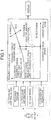
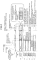
- FIG. 3 is a functional block diagram illustrating a structure related to a fuel-saving driving diagnostic device 10a and a HV traveling control device 20a of a vehicle 1a according to the example of an embodiment.
- the fuel-saving driving diagnostic device 10a includes a fuel-saving driving diagnostic unit 11, a fuel-saving driving rating unit 12, a fuel-saving driving advice generating unit 13, an in-vehicle network interface unit 14, and an output interface unit 15. Also, the fuel-saving driving diagnostic device 10a is connected to the HV traveling control device 20a via the in-vehicle network interface unit 14 and an in-vehicle network 100.
- the HV traveling control device 20a is a computer that performs HV traveling control, and includes a required torque calculating unit 21a, a HV eco zone information calculating unit 21b, a motor characteristics information managing unit 21c, and a vehicle model information managing unit 21d.
- a battery monitoring device 23 that monitors the state of a battery that accumulates power to be supplied to the motor for driving the vehicle is connected to the HV traveling control device 20a.
- An engine control device 24a that controls the gasoline engine for driving the vehicle, and a motor control device 24b that controls the motor for driving the vehicle arc also connected to the HV traveling control device 20a.
- a brake control device 25 is also connected to the HV traveling control device 20a.
- the brake control device 25 controls the mechanical brake in accordance with brake operations by the driver, and performs control so as to use the motor as a regeneration brake in accordance with shift lever operations of the driver.
- a vehicle speed sensor 26 that senses the current speed of the vehicle
- an accelerator operation quantity sensor 27 that senses the current quantity of the accelerator operation of the driver
- a shift sensor 28 that senses the current shift lever position of the vehicle and the current shift mode state of the vehicle
- a vehicle speed pulse signal added-up value storing unit 29 are connected to the HV traveling control device 20a.
- the vehicle speed pulse signal added-up value storing unit 29 stores a vehicle speed pulse signal added-up value that is incremented by 1 every time a pulse sensor provided on the inner diameter of each wheel of the vehicle 1a senses a vehicle speed pulse signal as the wheel rotates 360 degrees.
- the vehicle speed pulse signal added-up value is a value obtained by accumulating the number of rotations of the wheel.
- the travel distance of the vehicle 1a in a predetermined period of time (100 milliseconds, for example) can be calculated by calculating the difference in vehicle speed pulse signal added-up values obtained before and after the predetermined period of time passes, and multiplying the difference by the outer circumference of the wheel.
- the required torque calculating unit 21a of the HV traveling control device 20a calculates the required torque for accelerating the vehicle 1a in accordance with the quantity of the accelerator operation (the accelerator opening) conducted by the driver and sensed by the accelerator operation quantity sensor 27.
- the HV eco zone information calculating unit 21b of the HV traveling control device 20a calculates HV eco zone information in accordance with the vehicle speed, based on motor characteristics obtained from the motor characteristics information managing unit 21c, vehicle model information obtained from the vehicle model information managing unit 21d, the motor temperature monitored by the motor control device 24b, and the SOC of the battery monitored by the battery monitoring device 23.
- the HV eco zone information indicates the lower limit value and the upper limit value that define the HV eco range of the required torque at each vehicle speed.
- the HV eco zone information calculated by the HV eco zone information calculating unit 21b is transferred to a diagnosis condition managing unit 11a of the fuel-saving driving diagnostic device 10a.
- the diagnosis condition managing unit 11a stores the HV eco zone information as the lower limit values and the upper limit values at the respective vehicle speeds in the HV eco zone columns in an eco zone table depicted in FIG. 4 .
- the values stored in the eco zone columns of the eco zone table are calculated by an eco zone information calculating unit 11b as described above and are then stored.
- the vehicle power indication status quantity display unit 16a, the eco lamp 16b, and a display unit 16c having a display screen are connected to the fuel-saving driving diagnostic device 10a via the output interface unit 15.
- the fuel-saving driving diagnostic unit 11 includes the diagnosis condition managing unit 11a, the eco zone information calculating unit 11b, a vehicle power indication status quantity calculation determining unit 11c, an eco lamp lighting determining unit 11d, and a travel distance adding-up unit 11e.
- the diagnosis condition managing unit 11a manages the conditions under which driving is determined to be eco driving in the HV eco zone, and the conditions under which the vehicle power indication status quantity is in the HV eco zone range, and the eco lamp 16b is put into a lighting state.
- the eco zone table depicted in FIG. 4 a HV eco zone traveling determining conditions table depicted in FIG. 5 , and an eco lamp lighting determining conditions table shown in FIG. 6 are stored.
- the eco zone table depicted in FIG. 4 stores the lower limit value and the upper limit value of the HV eco zone of each vehicle speed range calculated by the HV eco zone information calculating unit 21b.
- the eco zone table also stores the lower limit value and the upper limit value of the eco zone of each vehicle speed range calculated by the later described eco zone information calculating unit 11b, based on the vehicle model information.
- the HV eco zone traveling determining conditions table depicted in FIG. 5 has vehicle power status indication quantity[%] and the like stored as the determination items for determining whether the traveling is within the HV eco zone range.
- the HV eco zone traveling determining conditions table stores the current values of the respective determination items, the diagnosis condition values (initial values), and diagnosis condition values (changed values).
- the current value P of the vehicle power indication status quantity in the HV eco zone traveling determining conditions table is the value obtained by dividing the required torque calculated by the required torque calculating unit 21a of the HV traveling control device 20a every 100 milliseconds by the upper limit value di (i being one of 1 through 7 in accordance with the current vehicle speed) of the eco zone of the current vehicle speed, referring to the eco zone table.
- the diagnosis condition values (the initial values) in the HV eco zone traveling determining conditions table are values calculated for each vehicle speed by the HV eco zone information calculating unit 21b, based on the upper limit value of the eco zone information, the motor characteristics, the vehicle model information, and the remaining battery level monitored by the battery monitoring device 23.
- the diagnosis condition values are values changed from the diagnosis condition values (the initial values) by the diagnosis condition managing unit 11a, based on map information supplied from a map information DB 17a of a car navigation device 17, and road conditions and traffic conditions received by a road information receiving device 18.
- the diagnosis condition values (the changed values) serve as values that relax or tighten the diagnosis condition values (the initial values).
- the road information receiving device 18 is a VICS (registered trademark) receiving device or a DSRC (Dedicated Short Range Communications; road-to-vehicle communications) device.
- VICS registered trademark
- DSRC Dedicated Short Range Communications; road-to-vehicle communications
- the eco lamp lighting determining conditions table depicted in FIG. 6 has the vehicle speed [k/m], the accelerator opening (the angle of the accelerator opening conducted by the driver) ⁇ [deg], the shift lever position, the shift mode state, and the like stored as the determination items for allowing the eco lamp 16b to light up.
- the eco lamp lighting determining conditions table stores the current values of the respective determination items, the diagnosis condition values (the initial values), and the diagnosis condition values (changed values).
- the current value v of the vehicle speed, the current value ⁇ of the accelerator opening, the shift lever position, and the shift mode state in the eco lamp lighting determining conditions table are values that are acquired from the vehicle speed sensor 26, the accelerator operation quantity sensor 27, and the shift sensor 28 via the HV traveling control device 20a every 100 milliseconds, for example.
- the shift lever position is “P” (Parking), “R” (Reverse), “D” (Drive; normal drive), “N” (Neutral), “B” (Break; regenerative braking by the motor), “2" (Second; second gear position), “1” (First: first gear position), or the like.
- "D” is selected as the shift lever position for driving, to realize fuel-saving driving.
- the shift mode state is a function to complement the shift lever selection and set the driving of the vehicle 1a, and this function can be switched on and off with a switch attached to the shift lever.
- the shift mode state is a "normal mode", an "eco mode” (a state where fuel-saving driving is performed), a "sport mode” (a state where sporty-type driving is performed), a “snow mode” (a state where safe driving is secured in the snow), or the like. Normally, the "normal mode” or the "eco mode” is selected as the shift mode state for driving, to perform fuel-saving driving.
- the diagnosis condition values (the initial values) in the eco lamp lighting determining conditions table are values that are set in advance.
- the diagnosis condition values (changed values) are values changed from the diagnosis condition values (the initial values) by the diagnosis condition managing unit 11a, based on map information supplied from the map information DB 17a of the car navigation device 17, and road conditions and traffic conditions received by the road information receiving device 18.
- the diagnosis condition values (the changed values) serve as values that relax or tighten the diagnosis condition values (the initial values).
- the reason that the diagnosis condition managing unit 11a relaxes or tightens the diagnosis condition values in accordance with the map information and the road and traffic conditions as described above is as follows.
- the indication and lighting of the vehicle power indication status quantity display unit 16a and the eco lamp 16b are information that indicates fuel-saving driving of the driver.
- the diagnosis condition managing unit 11a relaxes or tightens the diagnosis condition values in accordance with the map information and road and traffic conditions, to perform fair diagnoses and rating, and satisfy the user who is the driver.
- Relaxing or tightening the diagnosis condition values in accordance with the map information and road and traffic conditions is realized by shifting the lower limit value and the upper limit values represented by numerical values by 20 to 30%, and/or adding or deleting a condition with respect to the shift lever position and the shift mode state.
- the eco zone information calculating unit 11b calculates the eco zone information that contains the information about the upper limit value of the torque that can achieve acceleration without an excessive increase in fuel consumption at each vehicle speed even if a gasoline engine is used.
- the eco zone information has the lower limit value and the upper limit value at each vehicle in the eco zone column in the eco zone table.
- the vehicle power indication status quantity calculation determining unit 11c calculates the vehicle power indication status quantity by dividing the required torque T at the current vehicle speed v calculated by the required torque calculating unit 21a by the upper limit value (see FIG. 4 ) of the eco zone at the corresponding vehicle speed calculated by the eco zone information calculating unit 11b.
- the calculated vehicle power indication status quantity is displayed on the vehicle power indication status quantity display unit 16a.
- the vehicle power indication status quantity is the relative amount of the required torque calculated according to the above equation (1).
- the vehicle power indication status quantity calculation determining unit 11c determines whether the calculated vehicle power indication status quantity is within the range of the lower limit value to the upper limit value of the diagnosis condition value (changed value) for the vehicle power indication status quantity shown in FIG. 5 .
- driving is determined to be HV eco driving. This determination is called a fuel-saving driving diagnosis.
- the vehicle power indication status quantity calculation determining unit 11c determines whether the calculated vehicle power indication status quantity is within the range of the lower limit value to the upper limit value of the diagnosis condition values (the initial values) for the vehicle power indication status quantity shown in FIG. 5 .
- the eco lamp lighting determining unit 11d determines whether the current vehicle speed, the accelerator opening, the shift lever position, and the shift mode state (these will be referred to as the eco lamp lighting determination items) of the vehicle 1a acquired via the HV traveling control device 20a satisfy the respective diagnosis condition values (changed values) illustrated in FIG. 6 . This determination is also a fuel-saving driving diagnosis. When all the eco lamp lighting determination items satisfy the diagnosis condition values (changed values), the eco lamp lighting determining unit 11d lights the eco lamp 16b.
- the eco lamp lighting determining unit 11d determines whether the eco lamp lighting determination items are within the ranges of the lower limit values to the upper limits values of the respective diagnosis condition values (the initial values) illustrated in FIG. 6 .
- the travel distance adding-up unit 11e adds the 100-msec travel distance acquired from the vehicle speed pulse signal added-up value storing unit 29 via the HV traveling control device 20a every 100 milliseconds to a one-trip travel distance, an eco lamp lighting travel distance, a travel distance within the HV eco zone range, and a travel distance beyond the HV eco zone range.
- the one-trip travel distance is the distance the vehicle 1a traveled since the ignition was turned on until the ignition was turned off.
- the eco lamp lighting travel distance is the distance traveled within the one-trip travel distance, with the eco lamp 16b being on.
- the travel distance within the HV eco zone range is the distance traveled in the on-trip travel distance with the eco lamp 16b being on, and the vehicle power indication status quantity being within the HV eco zone range.
- the travel distance beyond the HV eco zone range is the distance traveled within the one-trip travel distance, with the vehicle power indication status quantity being beyond the HV eco zone range.
- the travel distance beyond the HV eco zone range has weighting coefficients by which the respective travel distances in accordance with overruns beyond the HV eco zone are to be multiplied, as shown in a HV eco zone overrun rank weighting coefficient table illustrated in FIG. 7 .
- FIG. 7 the following relationship is established: 1 ⁇ ⁇ 1 ⁇ ⁇ 2 ⁇ ⁇ 3.
- the travel distance beyond the HV eco zone range is calculated by: the overrun rank-A travel distance ⁇ ⁇ 1 + overrun rank-B travel distance ⁇ ⁇ 2 + overrun rank-C travel distance ⁇ ⁇ 3. In this manner, as the overrun beyond the HV eco zone range becomes larger, the travel distance beyond the HV eco zone range is multiplied by a larger coefficient.
- the fuel-saving driving rating unit 12 of the fuel-saving driving diagnostic device 10a rates the driving of the driver, based on the respective added-up values calculated by the travel distance adding-up unit 11e.
- Score of traveling within the HV eco zone range travel distance within HV eco zone range One-trip travel distance ⁇ 100 %
- Score of traveling beyond the HV eco zone range Travel distance beyond HV eco zone range
- One-trip travel distance Overrun rank ⁇ A travel distance ⁇ ⁇ 1 + Overrun rank ⁇ B travel distance ⁇ ⁇ 2 + Overrun rank ⁇ C travel distance ⁇ ⁇ 3 / One-trip travel distance ⁇ 100 %
- the score of an eco lamp lighting travel and the score of traveling within the HV eco zone range are "merit” scores for recognizing that the driver has performed fuel-saving driving.
- the score of traveling beyond the HV eco zone range is a "demerit” score for noting that the driver has failed to perform fuel-saving driving.
- the fuel-saving driving rating unit 12 then causes the display unit 16c to display the score of an eco lamp lighting travel, the score of traveling within HV eco zone range, and the score of traveling beyond the HV eco zone range shown as an example in FIG. 14 .
- a total score may be calculated, with the "merit" scores being point-addition components, the "demerit” score being a point-deduction component.
- the fuel-saving driving of the driver is rated by calculating the respective scores based on the respective travel distances. In this manner, fair, clear, and satisfactory rating results can be presented to the driver.
- the fuel-saving driving advice generating unit 13 of the fuel-saving driving diagnostic device 10a causes the display unit 16c to display fuel-saving driving advices illustrated as examples in FIG. 8 , in accordance with the score of an eco lamp lighting travel and the score of traveling within the HV eco zone range.
- the fuel-saving driving advice generating unit 13 also causes the display unit 16c to display fuel-saving driving advices illustrated as examples in FIG. 9 , in accordance with the score of traveling beyond the HV eco zone range.
- FIGS. 15 and 16 are diagrams each showing an exemplary display format in which the display unit 16c is caused to display a fuel-saving driving advice.
- the fuel-saving driving advice generating unit 13 may generate a message from a message template promptly in response to any of the score of an eco lamp lighting travel, the score of traveling within the HV eco zone range, and score of traveling beyond the HV eco zone range.
- FIG. 10 is a flowchart illustrating the procedures in the fuel-saving driving diagnosing operation. This operation is an operation to be performed every 100 milliseconds, for example.
- the diagnosis condition managing unit 11a first acquires the vehicle speed, the vehicle speed pulse sensor added-up value, the accelerator opening, the shift lever position, the shift mode state, the required torque, and the HV eco zone information from the HV traveling control device 20a (step S101).
- the travel distance adding-up unit 11e then calculates the 100-msec travel distance from the difference between the vehicle speed pulse sensor added-up value acquired previously and the vehicle speed pulse sensor added-up value acquired this time (step S102).
- the travel distance adding-up unit 11e adds the 100-msec travel distance calculated at step S102 to the one-trip travel distance (step S103).
- the eco zone information calculating unit 11b calculates the eco zone information at each vehicle speed, based on the vehicle model information (step S104).
- the diagnosis condition managing unit 11a acquires map information from the map information DB 17a (step S105).
- the diagnosis condition managing unit 11a determines whether the current position of the vehicle is a point where a change needs to be made to the diagnosis conditions (step S106). If it is determined to be a point where a change needs to be made to the diagnosis conditions ("Yes" at step S106), the operation moves on to step S107. If it is determined not to be a point where a change needs to be made to the diagnosis conditions ("No" at step S106), the operation moves on to step S108.
- the diagnosis condition managing unit 11a changes the diagnosis conditions for fuel-saving driving, based on the acquired map information.
- the vehicle power indication status quantity calculation determining unit 11c calculates the vehicle power indication status quantity, and displays the vehicle power indication status quantity on the vehicle power indication status quantity display unit 16a.
- the eco lamp lighting determining unit 11d then performs an eco lamp lighting determining operation (step S109).
- the eco lamp lighting determining operation will be described later in detail, with reference to FIG. 11 .
- the vehicle power indication status quantity calculation determining unit 11c determines whether the eco lamp 16b is on, and the vehicle power indication status quantity is within the HV eco zone range (step S110). If the eco lamp 16b is determined to be on, and the vehicle power indication status quantity is determined to be within the HV eco zone range ("Yes" at step S110), the operation moves on to step S111. If the eco lamp 16b is determined not to be on, and the vehicle power indication status quantity is determined not to be within the HV eco zone range ("No" at step S110), the operation moves on to step S112.
- the travel distance adding-up unit 11e adds the 100-msec travel distance calculated at step S102 to the travel distance within the HV eco zone range.
- the vehicle power indication status quantity calculation determining unit 11c determines whether the vehicle power indication status quantity is within the HV eco zone. If the vehicle power indication status quantity is determined to be within the HV eco zone range ("Yes" at step S112), the fuel-saving driving diagnosing operation comes to an end. If the vehicle power indication status quantity is determined not to be within the HV eco zone range ("No" at step S112), the 100-msec travel distance calculated at step S102 is added to the travel distance beyond the HV eco zone range (step S113). When this procedure is completed, the fuel-saving driving diagnosing operation comes to an end.
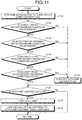
- FIG. 11 is a flowchart illustrating the procedures in the eco lamp lighting determining operation. As illustrated in the figure, the eco lamp lighting determining unit 11d first performs initialization to turn on an eco lamp lighting flag (step S121).
- the eco lamp lighting determining unit 11d determines whether the vehicle speed is within a diagnosis condition value range (step S122). If the vehicle speed is determined to be within the diagnosis condition value range ("Yes" at step S122), the operation moves on to step S123. If the vehicle speed is determined not to be within the diagnosis condition value range ("No" at step S122), the operation moves on to step S126.
- the eco lamp lighting determining unit 11d determines whether the accelerator opening is within a diagnosis condition value range (step S123). If the accelerator opening is determined to be within the diagnosis condition value range ("Yes" at step S123), the operation moves on to step S124. If the accelerator opening is determined not to be within the diagnosis condition value range ("No" at step S123), the operation moves on to step S126.
- the eco lamp lighting determining unit 11d determines whether the shift lever position satisfies a diagnosis condition value (step S124). If the shift lever position is determined to satisfy a diagnosis condition value ("Yes" at step S124), the operation moves on to step S125. If the shift lever position is determined not to satisfy a diagnosis condition value ("No" at step S124), the operation moves on to step S126.
- the eco lamp lighting determining unit 11d determines whether the shift mode state satisfies a diagnosis condition value (step S125). If the shift mode state is determined to satisfy a diagnosis condition value ("Yes" at step S125), the operation moves on to step S127. If the shift lever position is determined not to satisfy a diagnosis condition value ("No" at step S125), the operation moves on to step S126.
- the eco lamp lighting determining unit 11d turns the eco lamp lighting flag off.
- the eco lamp lighting determining unit 11d determines whether the eco lamp lighting flag is on. If the eco lamp lighting flag is determined to be on ("Yes" at step S127), the eco lamp lighting determining unit 11d lights an eco lamp 16d (step S128), and adds the 100-msec travel distance calculated at step S102 of FIG. 10 to the eco lamp lighting travel distance (step S129).
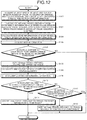
- step S104 may be carried out after step S102, and step S103 may be carried out if the determination result of step S106 is positive, as illustrated in FIG. 12 , with like step numbers being allotted to like procedures.
- steps S108 through S113 are carried out. If the determination result of step S106 is negative, the fuel-saving driving diagnosing operation is immediately performed.
- a diagnosis is not made when the current position of the vehicle is a point where a change needs to be made to the diagnosis conditions, and the 100-msec travel distance is not added to either of the one-trip travel distance and the travel distance within the HV eco zone range.
- a fair fuel-saving driving diagnosis can be made, with the driving conditions of the vehicle 1a and the traffic conditions and the like being taken into consideration.
- FIG. 13 is a flowchart illustrating the procedures in the fuel-saving driving rating result advice notifying operation.
- the fuel-saving driving rating unit 12 first determines whether one-trip traveling has been ended (step S201). If one-trip traveling is determined to have been ended ("Yes" at step S201), the operation moves on to step S202. If one-trip traveling is determined not to have been ended ("No" at step S201), step S201 is repeated.
- the fuel-saving driving rating unit 12 calculates an eco lamp lighting score, a score of traveling within the HV eco zone range, and a score of traveling beyond the HV eco zone range, based on the above described equations (2) through (4).
- the fuel-saving driving rating unit 12 then causes the display unit 16c to display the respective scores calculated through the procedures of step S202 (step S203).
- the fuel-saving driving advice generating unit 13 then causes the display unit 16c to display advising messages to increase the driver's awareness about fuel-saving driving in accordance with the eco lamp lighting score, the score of traveling within the HV eco zone range, and the score of traveling beyond the HV eco zone range (step S204).
- the fuel-saving driving rating result advice notifying operation comes to an end.
- the rating results and the fuel-saving driving advices are presented to the driver.
- the driver's awareness about fuel-saving driving can be raised and increased, and the driver can perform driving by sufficiently taking advantage of the environmental design of a hybrid vehicle.
- the HV traveling control device 20b may include a fuel-saving driving diagnostic unit 22, instead of the fuel-saving driving diagnostic device 10a including the fuel-saving driving diagnostic unit 11 in the vehicle 1a shown in FIG. 3 .
- the structures of the fuel-saving driving diagnostic device and the HV traveling control device differ from those of the above described embodiment, and the other aspects are the same as those of the above described embodiment. With this arrangement, the structure of the fuel-saving driving diagnostic device 10b can be simplified, and the processing load can be reduced.
- a diagnosis condition managing unit 22a, an eco zone information calculating unit 22b, a vehicle power indication status quantity calculation determining unit 22c, an eco lamp lighting determining unit 22d, and a travel distance adding-up unit 22e of the fuel-saving driving diagnostic unit 22 have the same functional structures as the diagnosis condition managing unit 11a, the eco zone information calculating unit 11b, the vehicle power indication status quantity calculation determining unit 11c, the eco lamp lighting determining unit 11d, and the travel distance adding-up unit 11e of the fuel-saving driving diagnostic unit 11, respectively.
- the eco lamp lighting determining unit 22d and/or the travel distance adding-up unit 22e may be included in the fuel-saving driving diagnostic device 10b, instead of the fuel-saving driving diagnostic unit 22.
- the vehicle power indication status quantity may be diagnosed and rated, before the eco lamp 16b is lighted.
- the conditions for diagnosing the vehicle power indication status quantity may be changed only with respect to the gravity to which the vehicle 1a is more subjected than in the case of flatland traveling. In that case, it is possible to use a gravity sensor, instead of the map information DB 17a.
- the values of conditions for diagnosing the vehicle power indication status quantity may be changed, with the weight of the passengers or cargo on board or the like being taken into account.
- the vehicle power indication status quantity may be then diagnosed and rated.
- a score may be increased at the time of rating. Also, at the time of rating, the weighting of the score may be changed in accordance with the usage rate of the charging power used for generating the required torque.
- the method for notifying the vehicle driver of the result of rating or an advice is not limited to displaying on the display unit 16c, but may involve acoustic or audio means.
- the conditions for diagnosing fuel-saving driving are relaxed or tightened by taking into consideration the driving conditions of the vehicle. Accordingly, the precision of fuel-saving driving diagnoses can be made higher, and the accuracy of fuel-saving driving rating can also be made higher.
- fair fuel-saving driving diagnoses are made by relaxing or tightening the predetermined fuel-saving driving diagnosis conditions, based on road conditions, traffic conditions, road surface conditions, weather conditions, or the like.
- Fuel-saving driving diagnosis conditions may be generated based on road conditions, traffic conditions, road surface conditions, weather conditions, or the like. Based on the generated fuel-saving driving diagnosis conditions, fuel-saving driving diagnoses may be made. Further, appropriate fuel-saving driving diagnosis conditions may be selected from the generated fuel-saving driving diagnosis conditions. Based on the selected fuel-saving driving diagnosis conditions, fuel-saving driving diagnoses may be made. In this manner, fairer fuel-saving driving diagnoses can be made, based on flexible fuel-saving driving diagnosis conditions varying with situations, instead of fixed fuel-saving driving diagnosis conditions.
- each of the components of each device shown in the drawings is merely functional and conceptual, and does not need to be physically structured as in the drawings.
- specific forms of separations and combinations of the devices are not limited to those shown in the drawings, but all of or part of them may be functionally or physically divided or integrated by an arbitrary unit, in accordance with various kinds of loads and the usage conditions.
- each processing function to be carried out in each device may be realized by a CPU (Central Processing Unit) (or a microcomputer such as a MPU (Micro Processing Unit) or a MCU (Micro Controller Unit)), or a program to be analyzed and executed by a CPU (or a microcomputer such as a MPU or MCU), or may be realized as hardware formed with wired logics.
- a CPU Central Processing Unit
- MPU Micro Processing Unit
- MCU Micro Controller Unit
- the disclosed fuel-saving driving diagnostic device, the fuel-saving driving diagnostic system, and the fuel-saving driving diagnostic method are effective to increase the driver's awareness about fuel saving driving, particularly fuel-saving acceleration and deceleration in driving, by diagnosing eco-friendly driving of the driver of the vehicle, rating the driving based on the diagnosis result, and returning the rating result and a fuel-saving driving advice based on the rating result to the driver.
Landscapes
- Engineering & Computer Science (AREA)
- Mechanical Engineering (AREA)
- Transportation (AREA)
- Chemical & Material Sciences (AREA)
- Combustion & Propulsion (AREA)
- Automation & Control Theory (AREA)
- Power Engineering (AREA)
- Sustainable Development (AREA)
- Sustainable Energy (AREA)
- Life Sciences & Earth Sciences (AREA)
- Human Computer Interaction (AREA)
- Electric Propulsion And Braking For Vehicles (AREA)
- Control Of Vehicle Engines Or Engines For Specific Uses (AREA)
- Hybrid Electric Vehicles (AREA)
- Combined Controls Of Internal Combustion Engines (AREA)
Claims (9)
- Diagnosevorrichtung (10a) für kraftstoffsparendes Fahrverhalten, die ein kraftstoffsparendes Fahrverhalten eines Fahrzeugs, das eine elektrische Antriebsvorrichtung zum Antreiben des Fahrzeugs unter Verwendung von Elektrizität als Energie und eine Kraftmaschine zum Antreiben des Fahrzeugs unter Verwendung eines fossilen Brennstoffs als Energie aufweist, diagnostiziert, umfassend:eine Einheit (21a) zum Berechnen eines benötigten Drehmoments, die ein benötigtes Drehmoment basierend auf dem Ausmaß der Beschleunigungsoperation durch den Fahrer berechnet;eine Diagnosezustandsverwaltungseinheit (11a), die das benötigte Drehmoment von der Einheit (21a) zum Berechnen des benötigten Drehmoments erhält und eine aktuelle Fahrzeuggeschwindigkeit des Fahrzeugs erhält;eine Einheit (21b) zum Berechnen von HV-Ökozoneninformationen, die HV-Ökozoneninformationen als eine Funktion einer Fahrzeuggeschwindigkeit des Fahrzeugs berechnet, die einen oberen Grenzwert und einen unteren Grenzwert eines Drehmoments umfassen, die einen HV-Ökobereich definieren, wobei der obere und der untere Grenzwert ferner auf Motormerkmalen, Fahrzeugmodellinformationen, der Motortemperatur und einem SOC der Batterie basieren, wobei der obere Grenzwert und der untere Grenzwert eines Drehmoments, die den HV-Ökobereich definieren, jeweils einen oberen Grenzwert und einen unteren Grenzwert eines Drehmoments angeben, wenn das Fahrzeug nur von der elektrischen Antriebsvorrichtung angetrieben wird;eine Ökozoneninformationsberechnungseinheit (11b), die Ökozoneninformationen, die einen oberen Grenzwert eines Drehmoments umfassen, als eine Funktion einer Fahrzeuggeschwindigkeit des Fahrzeugs basierend auf einem Fahrzeugmodell des Fahrzeugs berechnet, wobei der obere Grenzwert des Drehmoments für die Ökozone mit zunehmenden Fahrzeuggeschwindigkeiten zunimmt, und wobei der obere Grenzwert des Drehmoments für die Ökozone einer Beschleunigung ohne übermäßige Erhöhung des Kraftstoffverbrauchs entspricht, selbst wenn die Fossilbrennstoffkraftmaschine verwendet wird;eine Fahrzeugleistungsangabestatusmengenberechnungsbestimmungseinheit (11c), die einen prozentuellen Wert, welcher ein relatives Ausmaß des benötigten Drehmoments ist, durch Teilen des benötigten Drehmoments, das durch die Diagnosezustandsverwaltungseinheit (11a) erhalten wird, durch den oberen Grenzwert, der in den Ökozoneninformationen enthalten ist, die durch die Ökozoneninformationsberechnungseinheit (11b) berechnet werden, gemäß der aktuellen Fahrzeuggeschwindigkeit berechnet, bestimmt, ob das berechnete relative Ausmaß des benötigten Drehmoments innerhalb eines Bereichs liegt oder nicht, der der HV-Ökozone entspricht, die eine Zone ist, die durch den oberen Grenzwert und den unteren Grenzwert eines Drehmoments definiert ist, die den HV-Ökobereich definieren, wobei der obere Grenzwert des Drehmoments der HV-Ökozone einem prozentuellen Wert des oberen Grenzdrehmoments der Ökozone entspricht, der geringer als 100 % ist, und eine berechnete Fahrzeugleistungsangabestatusmenge auf einer Fahrzeugleistungsangabestatusmengenanzeigeeinheit (16a) anzeigt, wobei die angezeigte Fahrzeugleistungsangabestatusmenge angibt, ob das Fahrzeug innerhalb der HV-Ökozone, innerhalb der Ökozone oder außerhalb der Ökozone betrieben wird; und eine Ökolampenbeleuchtungsbestimmungseinheit (11d), die bestimmt, ob ein Ökolampenbeleuchtungsbestimmungselement zur Beleuchtung einer Ökolampe (16b) einen Diagnosezustandswert eines Ökolampenbeleuchtungsbestimmungselements einhält oder nicht, und die Ökolampe (16b) in einem Fall, wo das Ökolampenbeleuchtungsbestimmungselement den Diagnosezustandswert des Ökolampenbeleuchtungsbestimmungselements einhält, beleuchtet, wobei der Diagnosezustandswert des Ökolampenbeleuchtungsbestimmungselements gemäß Informationen, die von einer Kraftfahrzeugnavigationsvorrichtung (17) oder einer Straßeninformationsempfangsvorrichtung (18) erhalten werden, gelockert oder festgemacht wird, wobei die Fahrzeugleistungsangabestatusmenge diagnostiziert und bewertet wird, bevor die Ökolampe (16b) beleuchtet wird.
- Diagnosevorrichtung (10a) für kraftstoffsparendes Fahrverhalten nach Anspruch 1, wobei
die Diagnosezustandsverwaltungseinheit (11a) die HV-Ökozoneninformationen und den Diagnosezustandswert eines Ökolampenbeleuchtungsbestimmungselements gemäß einem Straßenzustand oder einem Verkehrszustand, die von der Diagnosezustandsverwaltungseinheit (11a) erhalten werden, ändert. - Diagnosevorrichtung (10a) für kraftstoffsparendes Fahrverhalten nach Anspruch 1 oder 2, ferner umfassend
eine Bewertungseinheit (12) für kraftstoffsparendes Fahrverhalten, die eine Auswertung des Fahrens innerhalb eines HV-Ökozonenbereichs durch Teilen durch eine Einwegfahrdistanz, die eine Fahrdistanz des Fahrzeugs vom Einschalten bis zum Ausschalten der Zündung des Fahrzeugs ist, einer Fahrdistanz innerhalb eines HV-Ökozonenbereichs, die eine Fahrdistanz des Fahrzeugs ist, wo die Ökolampe (16b) beleuchtet wird und die berechnete Fahrzeugleistungsangabestatusmenge innerhalb eines Bereichs der HV-Ökozone liegt, berechnet und die berechnete Auswertung des Fahrens innerhalb eines HV-Ökozonenbereichs auf einer Anzeigeeinheit (16c) anzeigt. - Diagnosevorrichtung (10a) für kraftstoffsparendes Fahrverhalten nach Anspruch 3, ferner umfassend
eine Hinweiserzeugungseinheit (13) für kraftstoffsparendes Fahrverhalten, die einen Hinweis auf kraftstoffsparendes Fahrverhalten, der eine Nachricht ist, basierend auf der Auswertung des Fahrens innerhalb eines HV-Ökozonenbereichs erzeugt, der durch die Bewertungseinheit (12) für kraftstoffsparendes Fahrverhalten berechnet wird, und den erzeugten Hinweis auf kraftstoffsparendes Fahrverhalten auf der Anzeigeeinheit (16c) anzeigt. - Diagnosevorrichtung (10a) für kraftstoffsparendes Fahrverhalten nach Anspruch 4, ferner umfassend
die Anzeigeeinheit (16c), die die Auswertung des Fahrens innerhalb eines HV-Ökozonenbereichs, die durch die Bewertungseinheit (12) für kraftstoffsparendes Fahrverhalten berechnet wird, und den Hinweis auf kraftstoffsparendes Fahrverhalten, der von der Hinweiserzeugungseinheit (13) für kraftstoffsparendes Fahrverhalten erzeugt wird, anzeigt. - Diagnoseverfahren für kraftstoffsparendes Fahrverhalten, das kraftstoffsparendes Fahrverhalten eines Fahrzeugs, das eine elektrische Antriebsvorrichtung zum Antreiben des Fahrzeugs unter Verwendung von Elektrizität als Energie und eine Kraftmaschine zum Antreiben des Fahrzeugs unter Verwendung eines fossilen Brennstoffs als Energie aufweist, diagnostiziert, umfassend:einen Schritt zur Berechnung des benötigten Drehmoments, der ein benötigtes Drehmoment basierend auf dem Ausmaß der Beschleunigungsoperation durch den Fahrer berechnet,einen Diagnosezustandsverwaltungsschritt, der das benötigte Drehmoment von dem Schritt zur Berechnung des benötigten Drehmoments erhält und eine aktuelle Fahrzeuggeschwindigkeit des Fahrzeugs erhält,einen HV-Ökozoneninformationsberechnungsschritt, der HV-Ökozoneninformationen als eine Funktion einer Fahrzeuggeschwindigkeit des Fahrzeugs berechnet, die einen oberen Grenzwert und einen unteren Grenzwert eines Drehmoments umfassen, die einen HV-Ökobereich definieren, wobei der obere und der untere Grenzwert ferner auf Motormerkmalen, Fahrzeugmodellinformationen, der Motortemperatur und einem SOC der Batterie basieren, wobei der obere Grenzwert und der untere Grenzwert eines Drehmoments, die den HV-Ökobereich definieren, jeweils einen oberen Grenzwert und einen unteren Grenzwert eines Drehmoments angeben, wenn das Fahrzeug nur von der elektrischen Antriebsvorrichtung angetrieben wird;einen Ökozoneninformationsberechnungsschritt, der Ökozoneninformationen berechnet, die einen oberen Grenzwert eines Drehmoments umfassen, als eine Funktion einer Fahrzeuggeschwindigkeit des Fahrzeugs basierend auf einem Fahrzeugmodell des Fahrzeugs, wobei der obere Grenzwert des Drehmoments für die Ökozone mit zunehmenden Fahrzeuggeschwindigkeiten zunimmt, und wobei der obere Grenzwert des Drehmoments für die Ökozone einer Beschleunigung ohne übermäßige Erhöhung des Kraftstoffverbrauchs entspricht, selbst wenn die Fossilbrennstoffkraftmaschine verwendet wird;einen Fahrzeugleistungsangabestatusmengenberechnungsbestimmungsschritt, der einen prozentuellen Wert, welcher ein relatives Ausmaß des benötigten Drehmoments ist, durch Teilen des benötigten Drehmoments, das durch den Diagnosezustandsverwaltungsschritt erhalten wird, durch den oberen Grenzwert, der in den Ökozoneninformationen enthalten ist, die durch den Ökozoneninformationsberechnungsschritt berechnet werden, gemäß der aktuellen Fahrzeuggeschwindigkeit berechnet, bestimmt, ob das berechnete relative Ausmaß des benötigten Drehmoments innerhalb eines Bereichs liegt oder nicht, der der HV-Ökozone entspricht, die eine Zone ist, die durch den oberen Grenzwert und den unteren Grenzwert eines Drehmoments definiert ist, die den HV-Ökobereich definieren, wobei der obere Grenzwert des Drehmoments der HV-Ökozone einem prozentuellen Wert des oberen Grenzdrehmoments der Ökozone entspricht, der geringer als 100 % ist, und eine berechnete Fahrzeugleistungsangabestatusmenge in einem Fahrzeugleistungsangabestatusmengeanzeigeschritt anzeigt, wobei die angezeigte Fahrzeugleistungsangabestatusmenge angibt, ob das Fahrzeug innerhalb der HV-Ökozone, innerhalb der Ökozone oder außerhalb der Ökozone betrieben wird; undeinen Ökolampenbeleuchtungsbestimmungsschritt, der bestimmt, ob ein Ökolampenbeleuchtungsbestimmungselement zur Beleuchtung einer Ökolampe (16b) einen Diagnosezustandswert eines Ökolampenbeleuchtungsbestimmungselements einhält oder nicht und die Ökolampe (16b) in einem Fall, wo das Ökolampenbeleuchtungsbestimmungselement den Diagnosezustandswert des Ökolampenbeleuchtungsbestimmungselements einhält, wobei der Diagnosezustandswert des Ökolampenbeleuchtungsbestimmungselements gemäß Informationen, die von einer Kraftfahrzeugnavigationsvorrichtung (17) oder einer Straßeninformationsempfangsvorrichtung (18) erhalten werden, gelockert oder festgemacht wird, wobei die Fahrzeugleistungsangabestatusmenge diagnostiziert und bewertet wird, bevor die Ökolampe (16b) beleuchtet wird.
- Diagnoseverfahren für kraftstoffsparendes Fahrverhalten nach Anspruch 6, wobei der Diagnosezustandsverwaltungsschritt die HV-Ökozoneninformationen und den Diagnosezustandswert des Ökolampenbeleuchtungsbestimmungselements gemäß einem Straßenzustand oder einem Verkehrszustand, die in dem Diagnosezustandsverwaltungsschritt erhalten werden, ändert.
- Diagnoseverfahren für kraftstoffsparendes Fahrverhalten nach Anspruch 6 oder 7, ferner umfassend einen Bewertungsschritt für kraftstoffsparendes Fahrverhalten, der eine Auswertung des Fahrens innerhalb eines HV-Ökozonenbereichs durch Teilen durch eine Einwegfahrdistanz, die eine Fahrdistanz des Fahrzeugs vom Einschalten bis zum Ausschalten der Zündung des Fahrzeugs ist, einer Fahrdistanz innerhalb eines HV-Ökozonenbereichs, die eine Fahrdistanz des Fahrzeugs ist, wo die Ökolampe (16b) beleuchtet wird und die berechnete Fahrzeugleistungsangabestatusmenge innerhalb eines Bereichs der HV-Ökozone liegt, berechnet und die berechnete Auswertung des Fahrens innerhalb eines HV-Ökozonenbereichs auf einer Anzeigeeinheit (16c) anzeigt.
- Diagnoseverfahren für kraftstoffsparendes Fahrverhalten nach Anspruch 8, ferner umfassend
einen Hinweiserzeugungsschritt für kraftstoffsparendes Fahrverhalten, der einen Hinweis auf kraftstoffsparendes Fahrverhalten, der eine Nachricht ist, basierend auf der Auswertung des Fahrens innerhalb eines HV-Ökozonenbereichs erzeugt, die in dem Bewertungsschritt für kraftstoffsparendes Fahrverhalten berechnet wird, und den erzeugten Hinweis auf kraftstoffsparendes Fahrverhalten auf der Anzeigeeinheit (16c) anzeigt.
Applications Claiming Priority (2)
| Application Number | Priority Date | Filing Date | Title |
|---|---|---|---|
| JP2008198382A JP4495234B2 (ja) | 2008-07-31 | 2008-07-31 | 省燃費運転診断装置、省燃費運転診断システム及び省燃費運転診断方法 |
| PCT/JP2009/063047 WO2010013617A1 (ja) | 2008-07-31 | 2009-07-21 | 省燃費運転診断装置、省燃費運転診断システム、電気駆動装置の制御装置、省燃費運転採点装置及び省燃費運転診断方法 |
Publications (3)
| Publication Number | Publication Date |
|---|---|
| EP2311683A1 EP2311683A1 (de) | 2011-04-20 |
| EP2311683A4 EP2311683A4 (de) | 2017-03-29 |
| EP2311683B1 true EP2311683B1 (de) | 2021-01-06 |
Family
ID=41610317
Family Applications (1)
| Application Number | Title | Priority Date | Filing Date |
|---|---|---|---|
| EP09802860.8A Active EP2311683B1 (de) | 2008-07-31 | 2009-07-21 | Diagnosevorrichtung für kraftstoffsparendes fahrverhalten, diagnosesystem für kraftstoffsparendes fahrverhalten, steuereinheit für elektrische antriebsvorrichtung, auswertungsvorrichtung für kraftstoffsparendes fahrverhalten und diagnoseverfahren für kraftstoffsparendes fahrverhalten |
Country Status (5)
| Country | Link |
|---|---|
| US (1) | US8655527B2 (de) |
| EP (1) | EP2311683B1 (de) |
| JP (1) | JP4495234B2 (de) |
| CN (1) | CN102105324B (de) |
| WO (1) | WO2010013617A1 (de) |
Families Citing this family (59)
| Publication number | Priority date | Publication date | Assignee | Title |
|---|---|---|---|---|
| DE102008028424A1 (de) * | 2008-06-17 | 2009-12-24 | Continental Automotive Gmbh | Verfahren zum Betrieb einer Steuereinrichtung eines Kraftfahrzeuges und Steuereinrichtung eines Kraftfahrzeuges zur Durchführung des Verfahrens |
| JP5300512B2 (ja) * | 2009-02-02 | 2013-09-25 | 矢崎総業株式会社 | 走行距離演算方法 |
| JP4692646B2 (ja) * | 2009-02-04 | 2011-06-01 | 株式会社デンソー | 動力発生源制御装置 |
| JP4670978B2 (ja) * | 2009-03-11 | 2011-04-13 | 株式会社デンソー | 省燃費運転支援装置、プログラム |
| DE112009005220B4 (de) * | 2009-09-11 | 2018-07-26 | Toyota Jidosha Kabushiki Kaisha | Hybridfahrzeug und ein Parameteranzeigeverfahren für ein Hybridfahrzeug |
| JP5440101B2 (ja) * | 2009-11-04 | 2014-03-12 | アイシン・エィ・ダブリュ株式会社 | 案内制御装置、案内制御方法、及び案内制御プログラム |
| WO2011092729A1 (ja) | 2010-01-26 | 2011-08-04 | 三菱電機株式会社 | ナビゲーション装置、車両情報表示装置および車両情報表示システム |
| US8502654B2 (en) | 2010-03-17 | 2013-08-06 | Ford Global Technologies, Llc | Vehicle information display and method |
| US8786418B2 (en) * | 2010-03-17 | 2014-07-22 | Ford Global Technologies, Llc | Ambient lighting to reflect changes in vehicle operating parameters |
| JP5316466B2 (ja) * | 2010-04-05 | 2013-10-16 | 三菱自動車工業株式会社 | 表示装置 |
| KR101664489B1 (ko) * | 2010-06-07 | 2016-10-12 | 현대모비스 주식회사 | 하이브리드 차량을 인식하는 하이브리드 트랜스폼 디스플레이 장치 및 방법 |
| DE102010048323A1 (de) * | 2010-10-13 | 2012-04-19 | Man Truck & Bus Ag | Fahrerassistenzsystem und entsprechendes Betriebsverfahren zur Anzeige oder Mitteilung einer Kraftstoffeinsparungssituation zur Senkung des Kraftstoffverbrauchs eines Kraftfahrzeugs |
| JP5273121B2 (ja) * | 2010-10-19 | 2013-08-28 | 株式会社デンソー | 発進支援装置 |
| US20120179314A1 (en) * | 2011-01-06 | 2012-07-12 | Ford Global Technologies, Llc | Vehicle Range Surplus Display And Method |
| CN102673568A (zh) * | 2011-03-10 | 2012-09-19 | 株式会社电装 | 省燃料费驾驶评价系统及方法、存储介质 |
| CN102673567B (zh) * | 2011-03-10 | 2016-01-20 | 株式会社电装 | 省燃费驾驶支援系统 |
| FR2972412B1 (fr) * | 2011-03-10 | 2016-01-01 | Renault Sas | Procede d'aide a une conduite economique en energie d'un vehicule automobile |
| DE102011015528A1 (de) * | 2011-03-30 | 2012-10-04 | GM Global Technology Operations LLC (n. d. Gesetzen des Staates Delaware) | Verfahren und Vorrichtung zum Beurteilen des Fahrverhaltens |
| WO2012147164A1 (ja) * | 2011-04-26 | 2012-11-01 | トヨタ自動車株式会社 | 車両制御装置 |
| JP5170286B2 (ja) | 2011-05-27 | 2013-03-27 | 日産自動車株式会社 | 減速情報伝達装置、減速情報伝達方法 |
| US9146131B2 (en) * | 2011-07-05 | 2015-09-29 | Aisin Aw Co., Ltd. | Evaluation indication system, evaluation indication method and computer-readable storage medium |
| US20130041552A1 (en) * | 2011-08-11 | 2013-02-14 | Ford Global Technologies, Llc | Methods and Apparatus for Estimating Power Usage |
| JP5725659B2 (ja) * | 2011-08-29 | 2015-05-27 | 本田技研工業株式会社 | 車両の瞬間燃費表示装置 |
| FR2985235B1 (fr) * | 2012-01-02 | 2014-03-14 | Peugeot Citroen Automobiles Sa | Procede d'aide a la conduite pour un vehicule hybride |
| US20130173136A1 (en) * | 2012-01-04 | 2013-07-04 | Samsung Electronics Co., Ltd. | Apparatus and method for displaying vehicle-driving information in mobile terminal |
| CN103247091B (zh) * | 2012-02-07 | 2016-01-20 | 厦门金龙联合汽车工业有限公司 | 一种驾驶评价系统及方法 |
| CN102849106B (zh) * | 2012-04-19 | 2014-10-29 | 北京理工大学 | 一种双侧电机驱动履带车辆转向系统 |
| DE102012008688B4 (de) * | 2012-04-28 | 2020-08-13 | Audi Ag | Verfahren zum Bestimmen eines zu erwartenden Verbrauchswertes eine Kraftwagens |
| FR2994923B1 (fr) | 2012-08-31 | 2015-11-27 | IFP Energies Nouvelles | Procede de determination d'un indicateur energetique d'un deplacement d'un vehicule |
| JPWO2014097408A1 (ja) * | 2012-12-18 | 2017-01-12 | トヨタ自動車株式会社 | 表示装置 |
| JP5887288B2 (ja) * | 2013-02-04 | 2016-03-16 | 日立建機株式会社 | ホイールローダ |
| BR112015019050A2 (pt) * | 2013-02-08 | 2017-07-18 | Toyota Motor Co Ltd | dispositivo de exibição |
| US9074894B2 (en) * | 2013-07-08 | 2015-07-07 | GM Global Technology Operations LLC | Vehicle range projection estimation |
| JP5913248B2 (ja) * | 2013-10-10 | 2016-04-27 | 富士重工業株式会社 | 車載用表示装置 |
| GB2519786A (en) * | 2013-10-30 | 2015-05-06 | Sergej Michailovic Kiprijanov | Multivalent antigen-binding protein molecules |
| FR3013643B1 (fr) * | 2013-11-27 | 2017-03-03 | Technoboost | Dispositif d'affichage pour vehicule hybride qui comprend un moteur a combustion interne et au moins une source de puissance motrice d'hybridation |
| US9824505B2 (en) * | 2014-02-25 | 2017-11-21 | Ford Global Technologies, Llc | Method for triggering a vehicle system monitor |
| DE102014006321A1 (de) * | 2014-04-30 | 2015-11-05 | Avl List Gmbh | System und Verfahren zur Analyse der Energieeffizienz eines Kraftfahrzeugs, insbesondere einer Vorrichtung des Kraftfahrzeugs |
| US20160089954A1 (en) * | 2014-09-30 | 2016-03-31 | Continental Automotive Systems Inc. | System and method for setting an environmental condition in or around a vehicle in response to a determined mood |
| JP2016089716A (ja) * | 2014-11-05 | 2016-05-23 | ヤマハ発動機株式会社 | 鞍乗型車両 |
| CN104442556B (zh) * | 2014-11-18 | 2016-11-02 | 观致汽车有限公司 | 一种与车辆有关信息的显示方法 |
| JP6024734B2 (ja) * | 2014-12-18 | 2016-11-16 | トヨタ自動車株式会社 | 運転支援装置 |
| US20170088119A1 (en) * | 2015-09-25 | 2017-03-30 | Parker-Hannifin Corporation | Adaptive power management for hybrid vehicles |
| DE102016207790A1 (de) | 2016-05-04 | 2017-11-09 | Volkswagen Aktiengesellschaft | Ausgabevorrichtung eines Kraftfahrzeugs und zugehöriges Betriebsverfahren |
| CN106240571B (zh) * | 2016-08-03 | 2019-01-25 | 东软集团股份有限公司 | 驾驶行为分析方法和装置 |
| US10137898B2 (en) * | 2016-11-03 | 2018-11-27 | Ford Global Technologies, Llc | Vehicle operator notification system |
| KR102638974B1 (ko) * | 2016-12-22 | 2024-02-22 | 현대자동차주식회사 | 연비 측정 장비 및 그 제어방법 |
| DE102017202638B4 (de) * | 2017-02-20 | 2022-04-28 | Ford Global Technologies, Llc | Vorrausschauendes Wärmemanagement für Kraftfahrzeuge |
| CN106740270B (zh) * | 2017-02-24 | 2019-04-09 | 北京新能源汽车股份有限公司 | 一种电机输出功率百分比的显示方法、装置及电动汽车 |
| BR112020011906A2 (pt) * | 2017-12-15 | 2020-11-24 | Nissan Motor Co., Ltd. | método de exibição de estado operacional e sistema de exibição de estado operacional |
| US11535230B2 (en) * | 2017-12-15 | 2022-12-27 | Nissan Motor Co., Ltd. | Fuel economy display control method and fuel economy display control system |
| GB2571335B (en) * | 2018-02-26 | 2020-09-02 | Jaguar Land Rover Ltd | A controller for a vehicle display system |
| GB2572743B (en) * | 2018-02-26 | 2020-09-02 | Jaguar Land Rover Ltd | A controller for a vehicle display system |
| US11858348B2 (en) * | 2018-02-26 | 2024-01-02 | Jaguar Land Rover Limited | Controller for vehicle display system |
| CN108973982B (zh) * | 2018-06-28 | 2020-06-23 | 浙江吉利控股集团有限公司 | 一种关于混动车型的驱动模式切换系统 |
| CN111497854B (zh) * | 2019-01-29 | 2022-01-14 | 长城汽车股份有限公司 | 评价驾驶员驾驶情况的方法和装置及机器可读存储介质 |
| JP2021046077A (ja) * | 2019-09-18 | 2021-03-25 | トヨタ自動車株式会社 | ハイブリッド自動車 |
| JP2022138726A (ja) * | 2021-03-10 | 2022-09-26 | トヨタ自動車株式会社 | 運転診断装置及び運転診断方法 |
| CN115782788B (zh) * | 2022-12-11 | 2024-04-12 | 中国重汽集团济南动力有限公司 | 一种整车内部需求扭矩协调控制方法及系统 |
Family Cites Families (29)
| Publication number | Priority date | Publication date | Assignee | Title |
|---|---|---|---|---|
| JP2900675B2 (ja) * | 1992-01-13 | 1999-06-02 | トヨタ自動車株式会社 | 車両走行特性変更装置 |
| JP3401181B2 (ja) * | 1998-02-17 | 2003-04-28 | トヨタ自動車株式会社 | ハイブリッド車の駆動制御装置 |
| JP2001231102A (ja) * | 2000-02-16 | 2001-08-24 | Mitsubishi Motors Corp | 電気自動車のモータ効率表示装置 |
| US6600413B1 (en) * | 2002-03-04 | 2003-07-29 | Jui-Yang Lo | Automobile efficiency meter |
| JP3915592B2 (ja) * | 2002-05-10 | 2007-05-16 | いすゞ自動車株式会社 | 省燃費運転評価装置および方法 |
| CN1953886B (zh) * | 2004-06-30 | 2011-05-18 | 福特汽车公司 | 车辆的信息显示器及其显示信息的方法 |
| US20070143002A1 (en) * | 2005-12-21 | 2007-06-21 | Crowell Thomas J | System for evaluating and improving driving performance and fuel efficiency |
| JP4424315B2 (ja) | 2006-02-10 | 2010-03-03 | トヨタ自動車株式会社 | ハイブリッド車用運転操作評価装置 |
| JP2007253727A (ja) * | 2006-03-22 | 2007-10-04 | Denso Corp | 表示装置と表示装置が表示する走行効率の算出方法 |
| JP5217103B2 (ja) * | 2006-03-24 | 2013-06-19 | トヨタ自動車株式会社 | 燃費表示装置 |
| DE102006017176A1 (de) * | 2006-04-12 | 2007-10-18 | Robert Bosch Gmbh | Geschwindigkeitsregelvorrichtung und Kraftfahrzeug mit einer solchen Geschwindigkeitsregelvorrichtung |
| JP4655007B2 (ja) * | 2006-08-29 | 2011-03-23 | 株式会社デンソー | 車両用表示装置 |
| JP4539638B2 (ja) * | 2006-10-25 | 2010-09-08 | トヨタ自動車株式会社 | アクセル開度表示装置 |
| WO2008050741A1 (fr) * | 2006-10-25 | 2008-05-02 | Toyota Jidosha Kabushiki Kaisha | Dispositif pour afficher un degré d'ouverture d'accélérateur et procédé pour afficher un degré d'ouverture d'accélérateur |
| JP4251210B2 (ja) * | 2006-11-07 | 2009-04-08 | トヨタ自動車株式会社 | ハイブリッド車両の表示装置 |
| JP4241837B2 (ja) * | 2007-01-15 | 2009-03-18 | トヨタ自動車株式会社 | 車両およびその制御方法 |
| JP4311451B2 (ja) * | 2007-01-16 | 2009-08-12 | トヨタ自動車株式会社 | 車両およびその制御方法 |
| JP2008174100A (ja) * | 2007-01-18 | 2008-07-31 | Toyota Motor Corp | ハイブリッド車の操作状態表示装置 |
| JP4345819B2 (ja) * | 2007-01-19 | 2009-10-14 | トヨタ自動車株式会社 | エコドライブ支援装置、エコドライブ支援方法 |
| JP4997986B2 (ja) * | 2007-01-19 | 2012-08-15 | トヨタ自動車株式会社 | ハイブリッド車両の制御装置 |
| JP5032180B2 (ja) * | 2007-03-31 | 2012-09-26 | 渉 堀川 | エコドライブ支援装置、カーナビゲーションシステム及びエコドライブ支援プログラム |
| JP4396723B2 (ja) * | 2007-04-03 | 2010-01-13 | トヨタ自動車株式会社 | 省エネルギ運転促進装置 |
| JP2009120092A (ja) * | 2007-11-16 | 2009-06-04 | Toyoda Gosei Co Ltd | エコドライブ表示計 |
| JP2009126246A (ja) * | 2007-11-20 | 2009-06-11 | Toyota Motor Corp | エコドライブ支援システム、並びに、そのシステムを構成するエコドライブ支援装置及び特典付与装置 |
| JP4456630B2 (ja) * | 2007-12-17 | 2010-04-28 | 富士通テン株式会社 | エコ運転状態表示装置 |
| JP4456631B2 (ja) * | 2007-12-17 | 2010-04-28 | 富士通テン株式会社 | エコ運転支援装置 |
| JP5143540B2 (ja) * | 2007-12-18 | 2013-02-13 | 富士通テン株式会社 | エコ運転支援装置 |
| JP2009156132A (ja) * | 2007-12-26 | 2009-07-16 | Fujitsu Ten Ltd | エコ運転支援装置 |
| US7898405B2 (en) * | 2008-03-25 | 2011-03-01 | Ford Global Technologies, Llc | Vehicle information display and method |
-
2008
- 2008-07-31 JP JP2008198382A patent/JP4495234B2/ja active Active
-
2009
- 2009-07-21 US US13/002,233 patent/US8655527B2/en active Active
- 2009-07-21 CN CN200980129275.2A patent/CN102105324B/zh active Active
- 2009-07-21 EP EP09802860.8A patent/EP2311683B1/de active Active
- 2009-07-21 WO PCT/JP2009/063047 patent/WO2010013617A1/ja active Application Filing
Non-Patent Citations (1)
| Title |
|---|
| None * |
Also Published As
| Publication number | Publication date |
|---|---|
| US20110125357A1 (en) | 2011-05-26 |
| CN102105324B (zh) | 2014-04-16 |
| US8655527B2 (en) | 2014-02-18 |
| JP2010041750A (ja) | 2010-02-18 |
| JP4495234B2 (ja) | 2010-06-30 |
| EP2311683A4 (de) | 2017-03-29 |
| CN102105324A (zh) | 2011-06-22 |
| WO2010013617A1 (ja) | 2010-02-04 |
| EP2311683A1 (de) | 2011-04-20 |
Similar Documents
| Publication | Publication Date | Title |
|---|---|---|
| EP2311683B1 (de) | Diagnosevorrichtung für kraftstoffsparendes fahrverhalten, diagnosesystem für kraftstoffsparendes fahrverhalten, steuereinheit für elektrische antriebsvorrichtung, auswertungsvorrichtung für kraftstoffsparendes fahrverhalten und diagnoseverfahren für kraftstoffsparendes fahrverhalten | |
| US8633812B2 (en) | Fuel-saving driving diagnostic device, fuel-saving driving diagnostic system, travel control device, fuel-saving driving rating device, and fuel-saving driving diagnostic method | |
| US8548670B2 (en) | Fuel-saving driving diagnostic device, fuel-saving driving diagnostic system, travel control device, fuel-saving driving rating device, and fuel-saving driving diagnostic method | |
| JP4689708B2 (ja) | 省燃費運転診断装置、原動機の制御装置及び省燃費運転診断方法 | |
| JP5549726B2 (ja) | 航続距離演算装置 | |
| US20140167944A1 (en) | Display device | |
| US8630792B2 (en) | Vehicle fuel cost-per-time display | |
| US20110118921A1 (en) | System and method for controlling economical driving of hybrid vehicle and a hybrid vehicle embodying same | |
| JP2011102801A (ja) | 自動車の走行可能距離を推定する方法 | |
| CN103863119B (zh) | 车辆用显示装置 | |
| JP2007274806A (ja) | ハイブリッド車両用電池情報表示装置 | |
| CA2722467A1 (en) | System and method for displaying power status of hybrid vehicle | |
| WO2014091591A1 (ja) | 車両制御装置 | |
| JP2002274219A (ja) | 車両の走行状態表示装置 | |
| US20130225362A1 (en) | Hybrid vehicle | |
| US20190039512A1 (en) | Vehicle display device | |
| JP2009126464A (ja) | 車両用表示装置 | |
| JP2013040575A (ja) | 省燃費運転評価システム及び省燃費運転評価システム用プログラム | |
| US9817018B2 (en) | Deceleration factor estimation apparatus | |
| JP5408921B2 (ja) | 省燃費運転診断装置、省燃費運転診断システム、走行制御装置、省燃費運転採点装置及び省燃費運転診断方法 | |
| JP5408920B2 (ja) | 省燃費運転診断装置、省燃費運転診断システム、走行制御装置、省燃費運転採点装置及び省燃費運転診断方法 | |
| JP4456630B2 (ja) | エコ運転状態表示装置 | |
| KR101849980B1 (ko) | Re-ev 에너지 모니터링 디스플레이 시스템 |
Legal Events
| Date | Code | Title | Description |
|---|---|---|---|
| PUAI | Public reference made under article 153(3) epc to a published international application that has entered the european phase |
Free format text: ORIGINAL CODE: 0009012 |
|
| 17P | Request for examination filed |
Effective date: 20110221 |
|
| AK | Designated contracting states |
Kind code of ref document: A1 Designated state(s): AT BE BG CH CY CZ DE DK EE ES FI FR GB GR HR HU IE IS IT LI LT LU LV MC MK MT NL NO PL PT RO SE SI SK SM TR |
|
| AX | Request for extension of the european patent |
Extension state: AL BA RS |
|
| DAX | Request for extension of the european patent (deleted) | ||
| RAP1 | Party data changed (applicant data changed or rights of an application transferred) |
Owner name: TOYOTA JIDOSHA KABUSHIKI KAISHA Owner name: FUJITSU TEN LIMITED |
|
| RA4 | Supplementary search report drawn up and despatched (corrected) |
Effective date: 20170227 |
|
| RIC1 | Information provided on ipc code assigned before grant |
Ipc: B60K 6/20 20071001ALI20170221BHEP Ipc: B60W 10/08 20060101ALI20170221BHEP Ipc: B60W 10/06 20060101ALI20170221BHEP Ipc: B60W 20/00 20160101ALI20170221BHEP Ipc: B60R 16/023 20060101ALI20170221BHEP Ipc: B60L 11/18 20060101ALI20170221BHEP Ipc: B60K 6/48 20071001ALI20170221BHEP Ipc: B60W 50/14 20120101ALI20170221BHEP Ipc: B60L 3/00 20060101AFI20170221BHEP Ipc: B60K 35/00 20060101ALI20170221BHEP Ipc: B60L 11/12 20060101ALI20170221BHEP Ipc: B60L 15/20 20060101ALI20170221BHEP Ipc: B60L 7/14 20060101ALI20170221BHEP |
|
| STAA | Information on the status of an ep patent application or granted ep patent |
Free format text: STATUS: EXAMINATION IS IN PROGRESS |
|
| 17Q | First examination report despatched |
Effective date: 20180406 |
|
| RIC1 | Information provided on ipc code assigned before grant |
Ipc: B60W 10/08 20060101ALI20170221BHEP Ipc: B60R 16/023 20060101ALI20170221BHEP Ipc: B60K 35/00 20060101ALI20170221BHEP Ipc: B60L 3/00 20190101AFI20170221BHEP Ipc: B60L 11/18 20060101ALI20170221BHEP Ipc: B60W 50/14 20120101ALI20170221BHEP Ipc: B60L 15/20 20060101ALI20170221BHEP Ipc: B60L 11/12 20060101ALI20170221BHEP Ipc: B60L 7/14 20060101ALI20170221BHEP Ipc: B60K 6/48 20071001ALI20170221BHEP Ipc: B60K 6/20 20071001ALI20170221BHEP Ipc: B60W 10/06 20060101ALI20170221BHEP Ipc: B60W 20/00 20160101ALI20170221BHEP |
|
| REG | Reference to a national code |
Ref country code: DE Ref legal event code: R079 Ref document number: 602009063247 Country of ref document: DE Free format text: PREVIOUS MAIN CLASS: B60L0003000000 Ipc: B60K0006480000 |
|
| GRAP | Despatch of communication of intention to grant a patent |
Free format text: ORIGINAL CODE: EPIDOSNIGR1 |
|
| STAA | Information on the status of an ep patent application or granted ep patent |
Free format text: STATUS: GRANT OF PATENT IS INTENDED |
|
| RIC1 | Information provided on ipc code assigned before grant |
Ipc: B60L 50/61 20190101ALI20200904BHEP Ipc: B60K 35/00 20060101ALI20200904BHEP Ipc: B60W 50/14 20200101ALI20200904BHEP Ipc: B60R 16/023 20060101ALI20200904BHEP Ipc: B60W 10/08 20060101ALI20200904BHEP Ipc: B60W 20/00 20160101ALI20200904BHEP Ipc: B60L 7/14 20060101ALI20200904BHEP Ipc: B60K 6/48 20071001AFI20200904BHEP Ipc: B60W 10/06 20060101ALI20200904BHEP Ipc: B60L 15/20 20060101ALI20200904BHEP Ipc: B60L 58/10 20190101ALI20200904BHEP |
|
| INTG | Intention to grant announced |
Effective date: 20201007 |
|
| GRAS | Grant fee paid |
Free format text: ORIGINAL CODE: EPIDOSNIGR3 |
|
| GRAA | (expected) grant |
Free format text: ORIGINAL CODE: 0009210 |
|
| STAA | Information on the status of an ep patent application or granted ep patent |
Free format text: STATUS: THE PATENT HAS BEEN GRANTED |
|
| AK | Designated contracting states |
Kind code of ref document: B1 Designated state(s): AT BE BG CH CY CZ DE DK EE ES FI FR GB GR HR HU IE IS IT LI LT LU LV MC MK MT NL NO PL PT RO SE SI SK SM TR |
|
| REG | Reference to a national code |
Ref country code: GB Ref legal event code: FG4D |
|
| REG | Reference to a national code |
Ref country code: DE Ref legal event code: R082 Ref document number: 602009063247 Country of ref document: DE Representative=s name: HL KEMPNER PATENTANWAELTE, SOLICITORS (ENGLAND, DE Ref country code: DE Ref legal event code: R082 Ref document number: 602009063247 Country of ref document: DE Representative=s name: HL KEMPNER PATENTANWALT, RECHTSANWALT, SOLICIT, DE |
|
| REG | Reference to a national code |
Ref country code: AT Ref legal event code: REF Ref document number: 1351974 Country of ref document: AT Kind code of ref document: T Effective date: 20210115 Ref country code: CH Ref legal event code: EP |
|
| REG | Reference to a national code |
Ref country code: DE Ref legal event code: R096 Ref document number: 602009063247 Country of ref document: DE |
|
| REG | Reference to a national code |
Ref country code: IE Ref legal event code: FG4D |
|
| REG | Reference to a national code |
Ref country code: NL Ref legal event code: MP Effective date: 20210106 |
|
| REG | Reference to a national code |
Ref country code: AT Ref legal event code: MK05 Ref document number: 1351974 Country of ref document: AT Kind code of ref document: T Effective date: 20210106 |
|
| REG | Reference to a national code |
Ref country code: LT Ref legal event code: MG9D |
|
| PG25 | Lapsed in a contracting state [announced via postgrant information from national office to epo] |
Ref country code: GR Free format text: LAPSE BECAUSE OF FAILURE TO SUBMIT A TRANSLATION OF THE DESCRIPTION OR TO PAY THE FEE WITHIN THE PRESCRIBED TIME-LIMIT Effective date: 20210407 Ref country code: HR Free format text: LAPSE BECAUSE OF FAILURE TO SUBMIT A TRANSLATION OF THE DESCRIPTION OR TO PAY THE FEE WITHIN THE PRESCRIBED TIME-LIMIT Effective date: 20210106 Ref country code: FI Free format text: LAPSE BECAUSE OF FAILURE TO SUBMIT A TRANSLATION OF THE DESCRIPTION OR TO PAY THE FEE WITHIN THE PRESCRIBED TIME-LIMIT Effective date: 20210106 Ref country code: LT Free format text: LAPSE BECAUSE OF FAILURE TO SUBMIT A TRANSLATION OF THE DESCRIPTION OR TO PAY THE FEE WITHIN THE PRESCRIBED TIME-LIMIT Effective date: 20210106 Ref country code: BG Free format text: LAPSE BECAUSE OF FAILURE TO SUBMIT A TRANSLATION OF THE DESCRIPTION OR TO PAY THE FEE WITHIN THE PRESCRIBED TIME-LIMIT Effective date: 20210406 Ref country code: NO Free format text: LAPSE BECAUSE OF FAILURE TO SUBMIT A TRANSLATION OF THE DESCRIPTION OR TO PAY THE FEE WITHIN THE PRESCRIBED TIME-LIMIT Effective date: 20210406 Ref country code: NL Free format text: LAPSE BECAUSE OF FAILURE TO SUBMIT A TRANSLATION OF THE DESCRIPTION OR TO PAY THE FEE WITHIN THE PRESCRIBED TIME-LIMIT Effective date: 20210106 Ref country code: PT Free format text: LAPSE BECAUSE OF FAILURE TO SUBMIT A TRANSLATION OF THE DESCRIPTION OR TO PAY THE FEE WITHIN THE PRESCRIBED TIME-LIMIT Effective date: 20210506 |
|
| PG25 | Lapsed in a contracting state [announced via postgrant information from national office to epo] |
Ref country code: SE Free format text: LAPSE BECAUSE OF FAILURE TO SUBMIT A TRANSLATION OF THE DESCRIPTION OR TO PAY THE FEE WITHIN THE PRESCRIBED TIME-LIMIT Effective date: 20210106 Ref country code: AT Free format text: LAPSE BECAUSE OF FAILURE TO SUBMIT A TRANSLATION OF THE DESCRIPTION OR TO PAY THE FEE WITHIN THE PRESCRIBED TIME-LIMIT Effective date: 20210106 Ref country code: LV Free format text: LAPSE BECAUSE OF FAILURE TO SUBMIT A TRANSLATION OF THE DESCRIPTION OR TO PAY THE FEE WITHIN THE PRESCRIBED TIME-LIMIT Effective date: 20210106 Ref country code: PL Free format text: LAPSE BECAUSE OF FAILURE TO SUBMIT A TRANSLATION OF THE DESCRIPTION OR TO PAY THE FEE WITHIN THE PRESCRIBED TIME-LIMIT Effective date: 20210106 |
|
| PG25 | Lapsed in a contracting state [announced via postgrant information from national office to epo] |
Ref country code: IS Free format text: LAPSE BECAUSE OF FAILURE TO SUBMIT A TRANSLATION OF THE DESCRIPTION OR TO PAY THE FEE WITHIN THE PRESCRIBED TIME-LIMIT Effective date: 20210506 |
|
| REG | Reference to a national code |
Ref country code: DE Ref legal event code: R097 Ref document number: 602009063247 Country of ref document: DE |
|
| PG25 | Lapsed in a contracting state [announced via postgrant information from national office to epo] |
Ref country code: SM Free format text: LAPSE BECAUSE OF FAILURE TO SUBMIT A TRANSLATION OF THE DESCRIPTION OR TO PAY THE FEE WITHIN THE PRESCRIBED TIME-LIMIT Effective date: 20210106 Ref country code: EE Free format text: LAPSE BECAUSE OF FAILURE TO SUBMIT A TRANSLATION OF THE DESCRIPTION OR TO PAY THE FEE WITHIN THE PRESCRIBED TIME-LIMIT Effective date: 20210106 Ref country code: CZ Free format text: LAPSE BECAUSE OF FAILURE TO SUBMIT A TRANSLATION OF THE DESCRIPTION OR TO PAY THE FEE WITHIN THE PRESCRIBED TIME-LIMIT Effective date: 20210106 |
|
| PLBE | No opposition filed within time limit |
Free format text: ORIGINAL CODE: 0009261 |
|
| STAA | Information on the status of an ep patent application or granted ep patent |
Free format text: STATUS: NO OPPOSITION FILED WITHIN TIME LIMIT |
|
| PG25 | Lapsed in a contracting state [announced via postgrant information from national office to epo] |
Ref country code: RO Free format text: LAPSE BECAUSE OF FAILURE TO SUBMIT A TRANSLATION OF THE DESCRIPTION OR TO PAY THE FEE WITHIN THE PRESCRIBED TIME-LIMIT Effective date: 20210106 Ref country code: SK Free format text: LAPSE BECAUSE OF FAILURE TO SUBMIT A TRANSLATION OF THE DESCRIPTION OR TO PAY THE FEE WITHIN THE PRESCRIBED TIME-LIMIT Effective date: 20210106 Ref country code: DK Free format text: LAPSE BECAUSE OF FAILURE TO SUBMIT A TRANSLATION OF THE DESCRIPTION OR TO PAY THE FEE WITHIN THE PRESCRIBED TIME-LIMIT Effective date: 20210106 Ref country code: ES Free format text: LAPSE BECAUSE OF FAILURE TO SUBMIT A TRANSLATION OF THE DESCRIPTION OR TO PAY THE FEE WITHIN THE PRESCRIBED TIME-LIMIT Effective date: 20210106 |
|
| 26N | No opposition filed |
Effective date: 20211007 |
|
| PG25 | Lapsed in a contracting state [announced via postgrant information from national office to epo] |
Ref country code: SI Free format text: LAPSE BECAUSE OF FAILURE TO SUBMIT A TRANSLATION OF THE DESCRIPTION OR TO PAY THE FEE WITHIN THE PRESCRIBED TIME-LIMIT Effective date: 20210106 |
|
| REG | Reference to a national code |
Ref country code: CH Ref legal event code: PL |
|
| PG25 | Lapsed in a contracting state [announced via postgrant information from national office to epo] |
Ref country code: MC Free format text: LAPSE BECAUSE OF FAILURE TO SUBMIT A TRANSLATION OF THE DESCRIPTION OR TO PAY THE FEE WITHIN THE PRESCRIBED TIME-LIMIT Effective date: 20210106 |
|
| REG | Reference to a national code |
Ref country code: BE Ref legal event code: MM Effective date: 20210731 |
|
| PG25 | Lapsed in a contracting state [announced via postgrant information from national office to epo] |
Ref country code: LI Free format text: LAPSE BECAUSE OF NON-PAYMENT OF DUE FEES Effective date: 20210731 Ref country code: IT Free format text: LAPSE BECAUSE OF FAILURE TO SUBMIT A TRANSLATION OF THE DESCRIPTION OR TO PAY THE FEE WITHIN THE PRESCRIBED TIME-LIMIT Effective date: 20210106 Ref country code: CH Free format text: LAPSE BECAUSE OF NON-PAYMENT OF DUE FEES Effective date: 20210731 |
|
| PG25 | Lapsed in a contracting state [announced via postgrant information from national office to epo] |
Ref country code: IS Free format text: LAPSE BECAUSE OF FAILURE TO SUBMIT A TRANSLATION OF THE DESCRIPTION OR TO PAY THE FEE WITHIN THE PRESCRIBED TIME-LIMIT Effective date: 20210506 Ref country code: LU Free format text: LAPSE BECAUSE OF NON-PAYMENT OF DUE FEES Effective date: 20210721 |
|
| PG25 | Lapsed in a contracting state [announced via postgrant information from national office to epo] |
Ref country code: IE Free format text: LAPSE BECAUSE OF NON-PAYMENT OF DUE FEES Effective date: 20210721 Ref country code: BE Free format text: LAPSE BECAUSE OF NON-PAYMENT OF DUE FEES Effective date: 20210731 |
|
| PG25 | Lapsed in a contracting state [announced via postgrant information from national office to epo] |
Ref country code: HU Free format text: LAPSE BECAUSE OF FAILURE TO SUBMIT A TRANSLATION OF THE DESCRIPTION OR TO PAY THE FEE WITHIN THE PRESCRIBED TIME-LIMIT; INVALID AB INITIO Effective date: 20090721 Ref country code: CY Free format text: LAPSE BECAUSE OF FAILURE TO SUBMIT A TRANSLATION OF THE DESCRIPTION OR TO PAY THE FEE WITHIN THE PRESCRIBED TIME-LIMIT Effective date: 20210106 |
|
| PG25 | Lapsed in a contracting state [announced via postgrant information from national office to epo] |
Ref country code: MK Free format text: LAPSE BECAUSE OF FAILURE TO SUBMIT A TRANSLATION OF THE DESCRIPTION OR TO PAY THE FEE WITHIN THE PRESCRIBED TIME-LIMIT Effective date: 20210106 |
|
| PG25 | Lapsed in a contracting state [announced via postgrant information from national office to epo] |
Ref country code: TR Free format text: LAPSE BECAUSE OF FAILURE TO SUBMIT A TRANSLATION OF THE DESCRIPTION OR TO PAY THE FEE WITHIN THE PRESCRIBED TIME-LIMIT Effective date: 20210106 |
|
| PG25 | Lapsed in a contracting state [announced via postgrant information from national office to epo] |
Ref country code: MT Free format text: LAPSE BECAUSE OF FAILURE TO SUBMIT A TRANSLATION OF THE DESCRIPTION OR TO PAY THE FEE WITHIN THE PRESCRIBED TIME-LIMIT Effective date: 20210106 |
|
| PGFP | Annual fee paid to national office [announced via postgrant information from national office to epo] |
Ref country code: DE Payment date: 20240719 Year of fee payment: 16 |
|
| PGFP | Annual fee paid to national office [announced via postgrant information from national office to epo] |
Ref country code: GB Payment date: 20240723 Year of fee payment: 16 |
|
| PGFP | Annual fee paid to national office [announced via postgrant information from national office to epo] |
Ref country code: FR Payment date: 20240729 Year of fee payment: 16 |