EP2310234B1 - Arrangement de siège de véhicule et arrangement de coussin gonflable pour un véhicule automobile ainsi que procédé pour protéger un passager d un véhicule - Google Patents
Arrangement de siège de véhicule et arrangement de coussin gonflable pour un véhicule automobile ainsi que procédé pour protéger un passager d un véhicule Download PDFInfo
- Publication number
- EP2310234B1 EP2310234B1 EP09780554.3A EP09780554A EP2310234B1 EP 2310234 B1 EP2310234 B1 EP 2310234B1 EP 09780554 A EP09780554 A EP 09780554A EP 2310234 B1 EP2310234 B1 EP 2310234B1
- Authority
- EP
- European Patent Office
- Prior art keywords
- vehicle
- vehicle seat
- inflatable element
- inflatable
- airbag
- Prior art date
- Legal status (The legal status is an assumption and is not a legal conclusion. Google has not performed a legal analysis and makes no representation as to the accuracy of the status listed.)
- Not-in-force
Links
Images


Classifications
-
- B—PERFORMING OPERATIONS; TRANSPORTING
- B60—VEHICLES IN GENERAL
- B60R—VEHICLES, VEHICLE FITTINGS, OR VEHICLE PARTS, NOT OTHERWISE PROVIDED FOR
- B60R21/00—Arrangements or fittings on vehicles for protecting or preventing injuries to occupants or pedestrians in case of accidents or other traffic risks
- B60R21/02—Occupant safety arrangements or fittings, e.g. crash pads
- B60R21/16—Inflatable occupant restraints or confinements designed to inflate upon impact or impending impact, e.g. air bags
- B60R21/20—Arrangements for storing inflatable members in their non-use or deflated condition; Arrangement or mounting of air bag modules or components
- B60R21/207—Arrangements for storing inflatable members in their non-use or deflated condition; Arrangement or mounting of air bag modules or components in vehicle seats
-
- B—PERFORMING OPERATIONS; TRANSPORTING
- B60—VEHICLES IN GENERAL
- B60R—VEHICLES, VEHICLE FITTINGS, OR VEHICLE PARTS, NOT OTHERWISE PROVIDED FOR
- B60R21/00—Arrangements or fittings on vehicles for protecting or preventing injuries to occupants or pedestrians in case of accidents or other traffic risks
- B60R21/02—Occupant safety arrangements or fittings, e.g. crash pads
- B60R21/16—Inflatable occupant restraints or confinements designed to inflate upon impact or impending impact, e.g. air bags
- B60R21/23—Inflatable members
- B60R21/231—Inflatable members characterised by their shape, construction or spatial configuration
- B60R21/233—Inflatable members characterised by their shape, construction or spatial configuration comprising a plurality of individual compartments; comprising two or more bag-like members, one within the other
-
- B—PERFORMING OPERATIONS; TRANSPORTING
- B60—VEHICLES IN GENERAL
- B60R—VEHICLES, VEHICLE FITTINGS, OR VEHICLE PARTS, NOT OTHERWISE PROVIDED FOR
- B60R21/00—Arrangements or fittings on vehicles for protecting or preventing injuries to occupants or pedestrians in case of accidents or other traffic risks
- B60R21/02—Occupant safety arrangements or fittings, e.g. crash pads
- B60R21/16—Inflatable occupant restraints or confinements designed to inflate upon impact or impending impact, e.g. air bags
- B60R21/23—Inflatable members
- B60R21/231—Inflatable members characterised by their shape, construction or spatial configuration
- B60R21/2334—Expansion control features
- B60R21/2338—Tethers
-
- B—PERFORMING OPERATIONS; TRANSPORTING
- B60—VEHICLES IN GENERAL
- B60R—VEHICLES, VEHICLE FITTINGS, OR VEHICLE PARTS, NOT OTHERWISE PROVIDED FOR
- B60R21/00—Arrangements or fittings on vehicles for protecting or preventing injuries to occupants or pedestrians in case of accidents or other traffic risks
- B60R21/02—Occupant safety arrangements or fittings, e.g. crash pads
- B60R21/16—Inflatable occupant restraints or confinements designed to inflate upon impact or impending impact, e.g. air bags
- B60R21/23—Inflatable members
- B60R21/237—Inflatable members characterised by the way they are folded
-
- B—PERFORMING OPERATIONS; TRANSPORTING
- B60—VEHICLES IN GENERAL
- B60R—VEHICLES, VEHICLE FITTINGS, OR VEHICLE PARTS, NOT OTHERWISE PROVIDED FOR
- B60R21/00—Arrangements or fittings on vehicles for protecting or preventing injuries to occupants or pedestrians in case of accidents or other traffic risks
- B60R21/02—Occupant safety arrangements or fittings, e.g. crash pads
- B60R21/16—Inflatable occupant restraints or confinements designed to inflate upon impact or impending impact, e.g. air bags
- B60R21/23—Inflatable members
- B60R21/231—Inflatable members characterised by their shape, construction or spatial configuration
- B60R2021/23107—Inflatable members characterised by their shape, construction or spatial configuration the bag being integrated in a multi-bag system
-
- B—PERFORMING OPERATIONS; TRANSPORTING
- B60—VEHICLES IN GENERAL
- B60R—VEHICLES, VEHICLE FITTINGS, OR VEHICLE PARTS, NOT OTHERWISE PROVIDED FOR
- B60R21/00—Arrangements or fittings on vehicles for protecting or preventing injuries to occupants or pedestrians in case of accidents or other traffic risks
- B60R21/02—Occupant safety arrangements or fittings, e.g. crash pads
- B60R21/16—Inflatable occupant restraints or confinements designed to inflate upon impact or impending impact, e.g. air bags
- B60R21/23—Inflatable members
- B60R21/231—Inflatable members characterised by their shape, construction or spatial configuration
- B60R21/2334—Expansion control features
- B60R21/2338—Tethers
- B60R2021/23382—Internal tether means
Definitions
- the present invention relates to a vehicle seat assembly for a motor vehicle according to claim 1 and a method for protecting a vehicle occupant according to claim 15.
- the genus-forming reveals DE 199 50 702 A1 a vehicle seat with an inflatable side wall.
- the DE 200 17 919 U1 describes a gas bag integrated in a vehicle seat, which emerges from a gap between a trim part and a padding of the vehicle seat.
- the problem to be solved by the invention is to provide an easily realizable and efficient protection for a vehicle occupant located on a vehicle seat.
- the inflatable element comprises a wrapping material that defines an inflatable chamber.
- the wrapping material is z. B. formed from a conventional airbag fabric, wherein two or more layers of the airbag material, in particular via an edge seam, may be connected to each other.
- other (e.g., elastic) materials may be considered as the shell material.
- the chamber of the inflatable element may also be directly limited by structures of the vehicle seat itself, so that the inflatable element does not have a separate covering material. This embodiment will be discussed in more detail below.
- the inflatable element extends flat when not inflated.
- the inflatable element which is not folded at all or simply folded, has an enveloping material that consists of one or more layers of material.
- a portion of the deflated inflatable element i. in particular, a portion of the wrapping material, inverted into the interior of the inflatable element.
- the inflatable element should be unfolded or simply folded, refers to the finished inflatable element.
- the inflatable element can certainly be made by folding over a Hüllmaterialzuitess and be folded again for placement in the vehicle seat, for example, such that after folding two sections of the outside of the inflatable element to each other.
- the inflatable element is designed and arranged such that, when inflated, it largely faces between a side of the installed vehicle seat which faces the vehicle longitudinal side closer to the vehicle seat (the two vehicle longitudinal sides facing one another) and Vehicle occupants extends.
- the inflatable element does not extend like a conventional side airbag predominantly between the vehicle seat and the vehicle longitudinal side, but in a region which is bounded on the one hand by a plane in which extends the vehicle longitudinal side facing side of the vehicle seat and on the other hand by the vehicle occupant.
- the inflatable element thus protrudes in the inflated state hardly or not at all in the space between the vehicle seat and the vehicle longitudinal side.
- the inflatable element For inflating the inflatable element in particular means are provided which inflate the inflatable element from the beginning of a collision of the motor vehicle.
- the means are activated by a control signal of a crash sensor of the vehicle; in particular, if it detects a side collision of the vehicle.
- the inflatable element has the function of protecting the vehicle occupant in the event of a collision actually occurring.
- the inflatable element is configured and arranged to exert a force (or impulse) on the vehicle occupant as it extends (impulsively) away from a vehicle side structure (vehicle longitudinal side).
- a force or impulse
- the vehicle occupant is moved away from a collision point of the vehicle by the inflatable inflatable element, in particular from a section of the vehicle longitudinal side closest to the vehicle seat, which is affected by a collision of the vehicle.
- the inflation of the inflatable element is in particular such that the force on the vehicle occupant is not so great that there is a risk of injury.
- the inflatable element thus exerts the force on the vehicle occupant moving it away from the collision location before coming into direct contact with a section of the vehicle side structure intruding into the vehicle interior. That is, moving the vehicle occupant away from the collision location is independent of the movement of the collision location toward the vehicle occupant, i. the vehicle occupant is not moved onto the inflatable element due to an impact of the intruding vehicle side structure. Only in the further course of the collision, d. H. if the vehicle side structure has penetrated into the interior in an advanced manner, an indirect or direct impact of the intruding structure with the vehicle occupant can occur, whereby the magnitude of the impact due to the extended absorption path is reduced.
- the inflatable element is formed in a variant of the invention, and arranged so that it acts predominantly on the rib area of the vehicle occupant.
- the force is transmitted predominantly in the region of the shoulder and / or the pelvis of the vehicle occupant.
- the vehicle seat arrangement has means for damping an impact of the vehicle occupant and / or a vehicle structure on the inflatable element.
- the means comprise an absorbing element which dissipates energy of the impacting structure or vehicle occupant.
- the means comprise a shock absorber structure, which is coupled to the inflatable element, or a discharge opening, from which gas can flow outward from the inflatable element.
- the discharge opening is permanently present in a casing material surrounding a chamber of the inflatable element.
- the discharge opening is closed at the beginning of the inflation of the inflatable element and is opened only at a predeterminable time after the start of inflation or it is formed only after a certain time in the inflatable element.
- the inflatable element is configured to exert force on the vehicle occupant in a first phase of expansion, while the means for damping an impact (of the vehicle occupant and / or an intruding vehicle structure) during a subsequent, second phase of expansion of the inflatable element to be activated.
- inflation of the inflatable element thus takes place first, without the means for damping the impact being activated.
- This allows in particular the most efficient transmission of power from the expanding inflatable element on the vehicle occupants and thus the most effective way moving the vehicle occupant.
- the means for damping an impact in this variant of the invention on a discharge opening of the inflatable element which is released after a certain time after the start of inflation of the inflatable element, so that the inflatable element in the initial phase expands as quickly as possible and as possible great impulse to the vehicle occupants.
- the discharge opening can, for. B. be controlled passively, d. H. in particular, comprise a mechanism which utilizes the expansion of the gas bag to release the discharge opening.
- This may for example be a band which is fixed to a shell material of the inflatable element and which is connected to a closure mechanism of the outflow opening.
- the opening of the discharge opening can also be active, in particular by a closure device which responds to a control signal of crash electronics of the vehicle and the outflow opening in response to the control signal z. B. pyrotechnic or electromechanical releases.
- the inflatable element and / or the means for inflating the inflatable element are activated in particular at the beginning of the collision.
- the inflation of the inflatable element is initiated even before the beginning of the actual collision in order to move the vehicle occupant as far away from the collision location as possible and to create the largest possible absorption path.
- the triggering of the inflatable element can thus already take place in response to a control signal of a pre-crash electronics of the vehicle.
- the inflatable element is reversibly inflatable, d. H. it may also be inflated for comfort purposes (e.g., to change the shape of the seat).
- the means for inflating the inflatable element are configured to allow repeated inflation of the inflatable element.
- the vehicle seat may also have a plurality of inflatable elements.
- several inflatable elements may each be designed in the form of a chamber of a multi-chamber element.
- the chambers are z. B. by a common Covering limited and each other z. B. delimited by seams, wherein it is not excluded that the chambers or some of the chambers are in fluid communication with each other.
- the inflatable element or the plurality of inflatable elements is / are beyond z. B. on or in a side cheek of the vehicle seat, which faces the vehicle occupant located on the seat.
- the side wall delimits in particular a middle part of a seat surface and / or a backrest of the vehicle seat. It can also be provided that in each case inflatable elements are arranged on opposite side cheeks of the vehicle seat.
- At least two inflatable elements - based on the installed state of the vehicle seat - along the vehicle height direction one above the other and / or at least two inflatable elements arranged transversely to the vehicle longitudinal direction side by side.
- the arrangement of several inflatable elements one above the other makes it possible in particular for a larger body section of the vehicle occupant (along its body length) to be covered by the inflatable element or for a force to be transmitted to the vehicle occupant over a larger body section.
- the inflatable elements arranged one above another are such that, when inflated, they do not substantially extend between the vehicle seat and the vehicle side structure closest to the vehicle seat.
- the inflatable elements arranged transversely to the vehicle longitudinal direction are in particular designed and arranged such that the forces in the direction of the vehicle occupant, which respectively arise during expansion of the inflatable elements, add up, so that an increased force (or pulse) relative to a single inflatable element the vehicle occupant acts.
- the juxtaposed multiple inflatable elements are configured and arranged so that they do not substantially extend between the vehicle seat and the vehicle seat nearest the vehicle seat when inflated.
- the plurality of inflatable elements which are arranged in the vehicle height direction one above the other or in the vehicle transverse direction side by side, either as separately manufactured elements, the z. B. are connected to each other, or may be formed as chambers of a multi-chamber element.
- the individual inflatable elements do not necessarily have to be filled at the same time. It is also conceivable that the inflatable elements successively or some of the inflatable elements are not filled. How or which of the inflatable elements are filled is determined in particular by control electronics of the vehicle, the type and severity of the collision and / or characteristics (height, body weight, etc.) of the vehicle occupant is detected.
- the inflatable element is arranged between a padding and a cover (eg fabric or leather) of the vehicle seat.
- the inflatable element is e.g. fixed to the upholstery and / or cover, d. H. connected via fasteners to the cover.
- the inflatable element may be connected to another structure of the vehicle seat.
- the purpose of connecting the inflatable element to a structure of the vehicle seat is, in particular, to dissipate forces which arise in the event of a collision of the vehicle occupant with the inflatable element or to hold the inflatable element in position upon impact of the vehicle occupant.
- the vehicle seat assembly may include attachment means by which the inflatable member is secured to a structure of the vehicle seat such that the direction of expansion of the inflatable member is affected.
- the fastening means comprise a band which connects a portion of a wrapping material of the inflatable element to the vehicle seat, the band controlling the main extension direction of the inflatable element.
- several such bands may be provided.
- the vehicle seat assembly according to the invention comprises a wrapping material delimiting a chamber of the inflatable element, wherein a connecting element is provided which connects two portions of an inner side of the wrapping material so that the direction of expansion of the inflatable element is influenced.
- the connecting element in the form of a band (“tether”) is formed. It can also be arranged several such bands.
- the vehicle seat assembly further comprises a gas bag, which extends in the deployed state largely between a vehicle side structure and the vehicle seat.
- a gas bag which extends in the deployed state largely between a vehicle side structure and the vehicle seat.
- a conventional airbag in particular a side airbag
- an intruding vehicle structure in particular a structure of a vehicle longitudinal side.
- such an additional conventional gas bag is not absolutely necessary due to the protective effect of the inflatable element.
- a means for inflating the inflatable element in particular a pyrotechnic gas generator is used, which is ignited at the time of collision of the vehicle.
- a pneumatic pressure source is used to inflate the inflatable element, e.g. can be supplemented with a conventional gas generator.
- the pneumatic pressure source may be used to inflate the inflatable element prior to or at the beginning of the actual collision, i. H. in a first phase of inflation while igniting the conventional (e.g., pyrotechnic) gas generator at a later second stage to assist in inflating the inflatable element.
- the means for inflating the inflatable element should additionally a conventional airbag be present, at the same time serve to inflate the conventional airbag.
- the inflatable element and the conventional airbag each have their own means for inflating.
- the inflatable element and the means for inflating the inflatable element are integrated in the vehicle seat, in particular in the backrest of the vehicle seat.
- these components are realized as a separate module, which is arranged during assembly of the vehicle seat or after assembly of the vehicle seat in this or on this.
- the inflatable element can be designed so that its effect is substantially independent of the type of vehicle, so that the inflatable element (or a module comprising the inflatable element and means for inflating the inflatable element) can be used for different types of vehicles is.
- Fig. 1 shows a vehicle seat assembly 1 mounted in a vehicle 2.
- the vehicle seat assembly 1 comprises a vehicle seat 3, which has an inflatable element 4 arranged in the region of its backrest 31.
- the inflatable element 4 is inflated when a crash sensor of the vehicle detects a collision on a side structure 21 (vehicle longitudinal side) of the vehicle.
- the force acting on the side structure due to the collision is indicated by the arrow K.
- the inflatable element 4 is designed and arranged such that, after being activated, it expands predominantly in the direction of a vehicle occupant 5 located on the seat and thus exerts a force F on the vehicle occupant 5 during expansion.
- the force F experienced by the vehicle occupant by the expanding inflatable element 4 moves it away from the side structure 21 and thus away from the collision location, thereby providing the absorption path available to energy of a vehicle longitudinal side structure 21, which intrudes under the action of the collision force K in the vehicle interior to dissipate.
- the inflatable element 4 is arranged on the vehicle seat such that, when inflated, it largely extends between a side 312 of the vehicle seat 3 which faces the vehicle longitudinal side 21 adjacent to the seat 3 and the vehicle occupant 5.
- a conventional side airbag extends in the inflated state in the space between the side 312 and the vehicle longitudinal side 21st
- Fig. 2 shows in a modification of the example not according to the invention Fig. 1 a vehicle seat assembly, which also has a conventional side airbag 6 in addition to the inflatable element 4.
- the vehicle occupant is moved away by the expanding inflatable element 4 from the side structure 21, which is affected by a collision.
- the absorption of energy of a structure intruding due to the collision is supported by the side gas bag 6 extending in the inflated state between the vehicle seat 3 and the vehicle longitudinal side 21.
- FIG. 3 Another variation of the example of Fig. 1 shows Fig. 3 , Here are two inflatable elements 4a, 4b arranged transversely to the vehicle longitudinal axis side by side, each exerting a force on the vehicle occupant 5, when they expand.
- the force of the outer (ie closer to the vehicle longitudinal side 21) arranged element 4b is transmitted predominantly indirectly via the inner inflatable element 4a on the vehicle occupants.
- the inflatable elements 4a, 4b are in particular arranged so that in the inflated state each extend largely between the side 312 of the vehicle seat on the vehicle occupant 5, ie they do not extend or only with a small proportion between the vehicle seat 3 (ie its side 312 ) and the vehicle longitudinal side 21.
- Fig. 4 shows a further modification of the example of Fig. 1 according to which two inflatable elements 4a, 4b are arranged one above the other in the vehicle height direction. With this arrangement, it is possible to act on a larger body portion of the vehicle occupant 5.
- the upper inflatable element 4 a is arranged in the shoulder region of the vehicle occupant, while the lower inflatable element 4 b extends from a rib area to a pelvic area of the vehicle occupant 5.
- FIGS. 2 to 4 also be combined with each other.
- several elements in vehicle height direction one above the other and simultaneously several elements in the vehicle transverse direction may be arranged side by side.
- a conventional side airbag, as in Fig. 2 be shown provided.
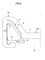
- Fig. 5 shows a horizontal section through a vehicle seat assembly not according to the invention in the amount of a backrest of the vehicle seat of the vehicle seat assembly.
- the backrest 31 has a side wall 311 which delimits a central part 314 of the backrest 31.
- a frame 313 is arranged, which stabilizes the backrest.
- the frame 313 is at least partially surrounded by a padding 7, which also forms a portion of the vehicle seat, which is to be located on the seat occupant (not shown).
- the padding 7 is surrounded by a cover 8, which forms an outer side of the vehicle seat.
- the padding 7 is z. B. formed by a foam-like material.
- an inflatable element 4 is arranged in the padding 7, an inflatable element 4 is arranged.
- the inflatable element has a wrapping material different from the material of the padding 7, which delimits an inflatable chamber 41.
- the shell material consists of a textile fabric, such as a conventional airbag material.
- the inflatable element 4 does not have a separate wrapping material, but the material of the padding 7 directly limits the inflatable chamber 41.
- the inflatable element is thus formed as a stretchable hollow space in the padding 7.
- the inflatable element 4 integrated in the padding 7 is inflated via means for inflating it in the form of a gas generator 9 (eg a micro gas generator).
- the gas generator 9 is integrated into the backrest 31 of the vehicle seat and attached via a holder 91, which may be fixed in particular to the frame 313.
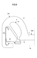
- Fig. 6 shows the inflatable element 4 in inflated or at least partially inflated state.
- the inflatable element 4 is arranged and arranged to extend substantially in the direction of a vehicle occupant (not shown) located on a vehicle seat, thus exerting, via padding 7, a force on the vehicle occupant to move the vehicle away from a collision location.
- the material of the padding is designed correspondingly stretchable, so that the inflatable element in its interior can expand substantially unhindered in the direction of the vehicle occupant.
- the padding 7 is such that it at least partially ruptures by the expansion of the inflatable element 4, and thus hampers the expansion of the inflatable element and the power transmission to the vehicle occupant as little as possible.
- the padding is designed so that it tears together with the cover 8 in two parts 7a, 7b.
- the vehicle occupant-facing part 7b is moved toward the vehicle occupant by the expanding inflatable member, so that a force is transmitted from the expanding inflatable member via the portion 7b of the pad 7 to the vehicle occupant.
- Fig. 8 shows a section through the backrest portion of a vehicle seat of a vehicle seat assembly according to the invention.
- the inflatable element 4 is disposed between the padding 7 and the cover 8.
- an enveloping material which delimits the inflatable chamber 41 of the element 4 extends between the padding 7 and the cover 8 (see section 8A).
- the inflatable element 4 does not have any wrapping material other than the cover or upholstery, but the inflatable element is formed directly by the upholstery and / or padding of the vehicle seat, i. the chamber 41 of the inflatable element is bounded by the cover 8 and / or the padding 7.
- the chamber 41 is separated in this variant by seams that define the reference to the padding.
- the inflatable element Indicates the inflatable element as in Fig. 8 a separate shell material, this can be fixed to the cover 7 and / or the padding.
- This is in sections B and C according to which the covering material 42 of the inflatable element 4 are fastened to the cover 8 or to the padding 7 via fastening means 45 (eg adhesive or a seam).
- the fastening means 45 also serve, in particular, to hold the inflatable element 4 in position upon impact of the vehicle occupant or of a vehicle structure (intruding, for example, in the vehicle interior) and / or to divert a force which acts on the inflatable element.
- Fig. 9 shows an arranged between the padding 7 and the seat cover 8 inflatable element 4 in at least partially inflated state.
- the seat cover 8 is formed so stretchable in this example that it impedes the expansion of the inflatable element as little as possible.
- the seat cover is torn by the expansion of the inflatable element, so that the inflatable element can expand unhindered.
- weakenings eg in the form of a perforation or a tear seam
- the vehicle seat assembly in this embodiment also has fastening means in the form of a band 100, via which a portion of the wrapping material 42 of the inflatable element is connected to a part 200 of the vehicle seat.
- the band 100 serves to influence the direction of expansion of the inflatable element, i. H. to help the inflatable element expand predominantly toward the vehicle occupant.
- the belt 100 may be configured and arranged to hold the inflatable element in position upon impact of the vehicle occupant and / or vehicle structure.
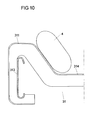
- Fig. 10 relates to a further variant of a non-inventive vehicle seat assembly, wherein again a sectional view through a backrest 31 of the vehicle seat of the vehicle seat assembly is shown.
- the inflatable element 4 is arranged in this variant from the outside to the backrest 31 (more precisely on the side cheek 311) and z. B. connected to the cover 8 and / or the padding 7 of the backrest 31.
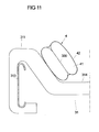
- Fig. 11 shows a development of the variant of Fig. 10 , wherein in the interior, ie in the chamber 41, of the inflatable element 4, a connecting element in the form of a tether 300 is arranged.
- the tether 300 connects portions of the inner surface of the wrapping material 42 to each other, so that the inflatable element 4 has a constriction in the inflated state.
- the tether 300 serves in particular to influence the direction of expansion of the inflatable element, in particular so that the inflatable element expands substantially in the direction of the vehicle occupant.
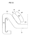
- Fig. 12 relates to a further modification of the variant of Fig. 10 in which two inflatable elements 4a, 4b are provided, each of which is designed as a chamber of a multi-chamber element 40.
- the multi-chamber element 40 has an enveloping material 402 which delimits the two chambers 4a and 4b.
- the two chambers are separated from one another by a separating element 403, whereby the separating element 300 passes through the interior of the wrapping material 402.
- the separating element 403 has an opening, so that an overflow of gas from one inflatable element into the other is possible.
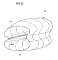
- Fig. 13 is a perspective view of a multi-chamber element 40, in which inflatable elements 4a, 4b are formed in the form of chambers. The chambers are separated by a partition 403.
- FIG. 13 Another embodiment of two inflatable elements is in Fig. 13 shown. Thereafter, two separately manufactured inflatable elements 4a, 4b abut one another in sections with their outer sides and are connected to one another via a connection 400 (eg in the form of a seam).
- a connection 400 eg in the form of a seam
- FIG. 15 shows a non-inventive airbag assembly with a gas bag 10, which is disposed on a z along the vertical vehicle axis z extending portion 22 of a body 2100 of a vehicle seat 20, wherein the main body 2100 is a seat frame of the vehicle seat 20 and at that area 22 um a portion of a back frame 23 of the vehicle seat 20, which is a part of the seat frame 2100.
- the back frame 23 forms a skeleton or a body of two back cheeks 25 of the vehicle seat 20, which protrude along the vehicle longitudinal axis x of a backrest 26 which extends in the zy plane, wherein the backrest 26 is usually pivotable about an axis extending along the vehicle transverse axis y axis (adjustable) is.
- the present considered backrest cheek 25 offers a occupant occupying the vehicle seat hold along the vehicle transverse axis y and is arranged adjacent to a lateral vehicle body.
- the vehicle seat 20 can also be a motor vehicle rear bench.
- the gas bag 10 is composed at least of a first airbag part 1000 and a second airbag part 101, which are interconnected along their outer peripheral edges, for example by means of a seam.
- the two airbag parts 1000, 101 can be separated be formed or integrally formed on each other. In the latter case, the two airbag parts 1000, 101 are folded along one axis and the superimposed edge portions of those airbag parts 1000, 101 connected to each other (so-called butterfly blank).
- the gas bag 10 thus formed is wrapped around the said area 22 of the main body 2100-here a back frame portion 22-so that the back frame portion 22 is arranged between the gas bag 10 along the vehicle transverse axis y.
- the gas bag 10 is divided into a first portion 110 and a second portion 111 connected thereto, wherein the transition from the first to the second portion 110, 111 along an end face 22a of the back frame portion 22, which faces the vehicle front.
- the first section 110 of the airbag 10 is arranged on an inner side 22b of the backrest frame section 22, which faces a occupant occupying the vehicle seat 20 as intended.
- the second section 111 of the airbag 10 is arranged on an outer side 22c of the backrest frame section 22 facing away from the inner side 22b.
- a gas generator 30 arranged in the first section 110 is provided, ie the gas generator 30 is arranged in a region of an interior of the airbag 10 defined by the section 110, the gas generator 30 being arranged on the inside 22b along the backrest frame section 22 extends and is secured to the said inner side 22b of the back frame portion 22.
- the gas bag 10 is also fastened to the back frame section 22 via the gas generator 30, for example by the gas generator 30 pressing a region of the gas bag 10 against the back frame section 22.
- Said back frame portion 22 is surrounded together with the gas bag 10 and inflator 30 secured thereto by a portion 4000 of a seat foam (seat foam portion 4000) of the vehicle seat 20, that seat foam forming an outer cover of the main body 2100 of the vehicle seat 20, which may be related to a final seat cover , That is, the seat foam portion 4000 has a recess 450, in which the airbag module (gas generator 30 and airbag 10) is arranged.
- the gas bag 10 can expand in the seat foam portion 4000 during inflation, is on one of the end face 22a of the back frame portion 22 facing wall 46th the recess 450 of the seat foam portion 4000 a recess 50 provided in the form of a groove which extends along said end face 22a.
- the seat foam portion 4000 can thus expand in cross-section - with unfolding of that groove 50 - so that the recess 450 of the seat foam portion 4000 can also accommodate an enlarged as a result of inflation gas bag volume.
- the airbag 10 is divided into the two sections 110, 111 as described above, the occupant to be protected is pushed away from the inside 22b of the back frame section 22 by the airbag 10 (due to the expansion of the seat foam section 4000), so that the occupant at the outside of the Lehmen frame section 22 directed action on the vehicle body can be transported away from the danger zone.
- a connection 60 between an edge region 111a of the second section 111 of the airbag 10 and the outer side 22c of the back frame section due to the pressure prevailing in the airbag pressure can be released, so that the airbag deploys in the xz plane.
- the gas bag may pierce a predetermined breaking point 47 of the seat foam section 4000 (cf. FIG. 20 ).
- FIG. 16 shows a modification of the in FIG. 15 shown gas bag assembly, in which the second portion 111 of the airbag 10 in contrast to FIG. 15 is not disposed on the outer side 22c of the back frame portion 22, but along the vehicle transverse axis y between the first portion 110 and the back frame portion 22.
- Both in the FIG. 15 as well as at the FIG. 16 Both sections 110, 111 preferably extend along the xz plane prior to inflation and preferably have the same area.
- the edge portion 111 a of the second portion via the connection 60 is not connected to the outside 22 b of the back frame portion, but with the inside 22 b of the back frame portion.
- FIG. 17 shows in connection with the FIG. 18 with reference to a schematic, sectional sectional view of a modification of the in FIGS. 15 and 16 shown gas bag assembly.
- an additional abutment member 70 is provided, with a first part 71 which extends flat in the xz plane and over the abutment member 70 is connected to the back frame portion 22. From a vehicle front facing, along the vertical axis of the vehicle extending edge 72 of the abutment member 70 is a second part 73 of the abutment member 70 in the direction of the occupant to be protected, which is integrally formed on the first part 71 and inclined to the xz plane along the vertical vehicle axis z extends, so that said edge 72 is formed at an acute angle with respect to the xy plane.
- the above-mentioned planes are spanned by the vehicle longitudinal axis x and the vertical vehicle axis z or by the vehicle longitudinal axis x and the vehicle transverse axis y. According to the FIG. 18 If said edge 72 can also be formed at an obtuse angle.
- the abutment element 70 can form a carrier of an airbag module, that is, both the gas bag 10 and the gas generator 30 and possibly the seat foam section 4000 can be fastened to the abutment element (carrier) 70.
- the entire airbag module is then fixed to the backrest frame section 22 or the region 22 via the abutment element.
- the gas bag 10 can be supported during inflation and thus displace the occupant effectively obliquely forwards towards the vehicle front (due to the inclination of the second part 73, there is a component of movement along the vehicle transverse axis y) Interior).
- the first part 71 of the abutment element 70 is located at a closer to the vehicle front, along the vertical vehicle axis z extending edge region 74 of the abutment member 70, so that the abutment member 70 engages around the end face 22a of the back frame portion 22 in cross-section, ie, the said end face 22a is arranged along the vehicle transverse axis y between the first and the second part 71, 73.
- the gas generator 30 may also be arranged along the vehicle transverse axis y between the first and the second part 71, 73 of the abutment element 70. In this case, the gas generator 30 may be fastened to the abutment element 70 and / or to the backrest frame section 22. Alternatively, the gas generator is arranged on the outer side 22c of the back frame section 22 and fastened there to the back frame section 22.
- the gas bag 10 extends before inflating along a surface 73 a facing the occupant of the second part 73 of the abutment element 70 and is thereby turned over so that the two sections 110, 111 of the airbag 10 are stacked and parallel are arranged to said surface 73a.
- the second section 111 is preferably arranged along a normal N to the surface 73a between the said surface 73a and the first section 111. That is to say, the gas bag rests against the surface 73a of the abutment element 70 via the second section 111.
- a supply line 80 is provided, which is preferably made of an airbag material.
- the supply line 80 can be discharged from the gas generator 30 into the first section or the second section.
- the feed line 80 can be guided through a passage opening 90 of the first part 71 of the abutment element 70 and possibly through a passage opening 90 of the second part 72. It is also possible to feed the feed line 80 around the abutment element 70 around set. In a gas generator 30 fixed to the abutment element 70, the feed line 80 can be guided through a through-opening 90 of the second part 73 or can be placed around the second part 73.
- a seat foam section 4000 surrounding the airbag module (gas bag, gas generator, supply line and abutment element) is provided (cf. FIGS. 15 and 16 ).
- the additional abutment member 70 is not as in the FIGS. 17 and 18 formed by a preferably made of metal element, but consists of a foam, which is, however, harder than a surrounding seat foam of the vehicle seat 20 is formed.
- the airbag module gas bag, gas generator
- the gas generator 30 is preferably fastened to the edge region 73 of the backrest frame section 22, in particular with a screw connection which is screwed from the inside 22b of the back frame section 22, wherein the gas generator 30 itself is arranged on the front side 22a of the back frame section 22.
- the abutment element 70 consisting of foam has at least the first part 73, via which the gas bag 10 can support itself as it is inflated, as described above.
- FIG. 20 shows a modification of the in FIG. 17 shown gas bag assembly, in contrast to FIG. 17 the abutment element 70 forms a housing for the gas generator 30, which is fastened via the abutment element 70 on the back frame section 22, wherein the gas generator is arranged on the front side 22a of the backrest frame section 22 and is surrounded in the xy plane by the abutment element 70 at least from three sides.
- the abutment element 70 is correspondingly curved in the said cross-sectional plane, so that it can embrace the said end face 22a with the gas generator 30 attached thereto.
- the abutment element 70 has two edge regions 74a, 74b extending along the vertical vehicle axis z, wherein the abutment element 70 is connected to the outside 22c of the back frame section 22 via a first edge region 74a and to the inside 22b of the back frame section 22 via the second edge region 74b.
- the abutment element 70 is bolted via the first edge region 74a from the outside 22c forth with the back frame portion 22 (via a screw 77, which is introduced from the outside 22c of the back frame portion 22 forth in a corresponding through hole of the back frame portion 22) and with the second edge region 74b suspended from the inside 22b forth in the back frame portion 22, wherein a portion of the second edge portion 74b engages behind a portion of the back frame portion 22.
- the gas bag 10 itself is according to the FIG. 15 wrapped around the abutment member 70 so that the first portion 110 rests against an occupant facing inner side 70a of the abutment member 70 and the second portion on an inner side 70a facing away from the outer side 70b of the abutment member 70th
- the gas bag 10 is preferably suspended on the inner side 70a of the abutment element 70 and fixed on the outer side 70b of the abutment element 70 via the said screw 77 on the abutment element 70.
- This connection of the second section 111 of the airbag 10 may be designed to be released during inflation of the airbag 10, so that the second section 111 may possibly unfold along the x-z plane.
- the abutment element 70 preferably forms a support of an airbag module which carries the gas bag, the gas generator and possibly the section 4000 of the seat foam, ie these components are fastened to the carrier and are preferably conveyed via this carrier to the back frame section 22 or area 22 established.
- FIG. 21 shows a variant in which the main body 2100 of the vehicle seat 20 is formed by a seat shell, which is covered on a vehicle front side facing by a seat foam.
- that region 22 of the main body 2100 is replaced by a along the vertical vehicle axis z extended portion of the seat 2100 formed, which forms part of a backbone for a backrest cheek 25 of the vehicle seat 20.
- This has an inner side 22a, which faces the occupant to be protected and extends along the xz plane, on which the abutment element 70 formed as a housing is fixed.
- the gas bag 10 folded in the manner of FIG.
- the abutment element 70 embodied as a housing is covered by a seat foam section 4000 on a side facing away from the inside 22a.
- the abutment member 70 forms a carrier of the airbag module.
- FIG. 22 shows an alternative arrangement or convolution of the airbag 10.
- the gas generator 30 is disposed on the outer side 22c of the back frame portion 22 and connected by a supply line 80 to the airbag 10, which is arranged on the inner side 22b of the back frame portion 22, wherein that feed line 80th is guided through a passage opening 90 of the back frame portion 22 to the airbag 10 and there opens centrally into the first portion 110 of the airbag 10, and off a circumferential seam 201 through which a first airbag portion 2001 of the first portion 110 of the airbag 10 with a peripheral region 202a of circulating second airbag part 202 is connected.
- that first airbag part 2001 extends flat along the inner side 22b of the backrest frame section 22.
- FIG. 23 shows a variant of a non-inventive airbag assembly or a non-inventive airbag module, wherein the airbag 10 in contrast to the FIGS. 15 to 22 is not covered by a seat foam portion 4000, but is spread over this area, said seat foam portion 4000 surrounds the back frame portion 22 in cross section. Accordingly, the gas bag 10 is wrapped around the back frame portion 22, so that the first portion 110 of the airbag 10 on the inside 22 a
- the gas generator 30 is embedded on the inside 22b of the back frame section 22 in the seat foam section 4000 and can be foamed in particular in those seat foam section 4000. As a result, the gas generator 30 is fixed relative to the backrest frame section 22.
- the gas generator 30 may be arranged in the first section 110. Alternatively, a supply line 80 may be provided, via which the gas generator 30 may be connected to the first section 110.
- FIG. 24 shows a modification of the in FIG. 22 shown gas bag assembly, in which the gas bag 10 in contrast to FIG. 22 has no bellows shape, but is divided into three sections 110, 111 and 112, wherein the first portion 110, in which the feed line 80 of the gas generator 30 opens, along the inner side 22b of the back frame portion 22 is extended and along the end face 22a in the second section 111, which extends flat along the outer side 22c.
- the first and second sections 110, 111 of the airbag 10 are therefore placed around the backrest frame section 22.
- the third section 112 of the airbag 10, which integrally adjoins the second section 111, is folded over onto the first and second sections 110, 111 so that it covers the first and second sections 110, 111.
- the gas bag 10 is according to FIG. 25 which is a modification of the in the FIG. 24 shown gas bag assembly, only according to FIG. 15 divided into two sections 110, 111, wherein the gas bag 24 according to FIG. 25 having a butterfly cut. That is, the airbag 10 has a first airbag part 3000 and a second airbag part 301, which are integrally formed along a folding axis 302 and are folded along this folding axis 302 to each other.
- the outer edge sections of the two airbag parts 3000, 301 which come to lie on top of each other are connected to one another by means of a connection 305, in particular in the form of a seam.
- the folding axis 302 runs along the vertical vehicle axis z along the inside 22b of the backrest frame section 22 and lies opposite the gas generator 30 along the vehicle transverse axis y.
- FIG. 26 shows a modification of the in FIG. 16 shown gas bag assembly in which the gas bag10 is taken, so that the first and the second portion 110, 111 respectively with their edge portions 110a, 111b, which are along the vertical vehicle axis z are adjacent to the end face 22a of the back frame portion 22 are arranged.
- the gas bag 10 is further foamed into the surrounding seat foam portion 4000, wherein on the gas bag 10, a plurality of openings 4001 is formed through which foam can penetrate during foaming in an inner space defined by the gas bag 10. As a result, the airbag 10 is anchored in the seat foam.
- FIG. 27 Such openings 4001 are provided, in contrast to FIG. 26 two separate airbags 10a and 10b are provided which extend in the non-inflated state in each case flat along the inner side 22b of the back frame portion 22 and are arranged congruently one above the other.
- FIG. 31 shows a modification of the in FIG. 26 shown gas bag assembly in which the gas bag 10 in contrast to FIG. 26 according to the FIG. 16 is formed and in addition the basis of the FIG. 26 having openings 4001 described.
- FIGS. 26, 27 and 31 can the superposed airbag parts 500, 501 of the gas bags 10, 10a, 10b shown there also according to FIG. 33 are glued together and with the surrounding seat foam portion 4000 to permanently position the gas bags 10, 10a, 10b with respect to the seat foam, which bonds dissolve when the respective gas bags 10, 10a, 10b are inflated.
- the two gas bags 10a and 10b can be made according to FIG. 28 can also be arranged in a recess 450 of the seat foam section 4000, wherein a wall 4100 of the recess 450 may have an opening to the occupant, so that the two gas bags 10a, 10b covering wall 4100 when inflating the airbags 10a, 10b through the airbags 10a, 10b can be deflected in the direction of the occupant.
- wall 4100 may be wrapped around the airbag (s) 10, 10a, 10b, or around the back frame section 22, such that a relatively large portion of the seat foam section 4000 is hinged toward the occupant.
- This hinged wall 4100 shields the occupants in a side crash additionally.
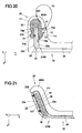
- FIG. 30 can the seat foam portion 4000 according to FIG. 29 as well as all the above-described seat foam sections 4000 on the airbag module (comprising gas bag 10, 10a, 10b, gas generator 30 and possibly abutment element 70 or a carrier or a housing of the airbag module) prefixed or fastened, wherein those seat foam section 4000 during assembly of the airbag module at the airbag modules described above preferably front side, ie, takes place from the end face 22a of the back frame portion 22 ago, is arranged in a provided on the seat foam of the vehicle seat recess.
- FIG. 32 shows this with reference to a schematic, sectioned section through a vehicle seat 20 along the yz plane.
- the airbag module according to FIG. 30 preferably has the seat foam section 4000, which envelops the gas bag 10 and is preferably preformed such that the seat foam section is curved and can embrace the back frame section 22 in such a way that the gas bag 10 extending in the section 4000 corresponds to FIG FIG. 15 is wrapped around the back frame portion 22 when the airbag module is mounted on the vehicle seat 20.
- a supply line 80 along the vehicle longitudinal axis x out which connects the airbag 10 (first portion 110) with the gas generator 30 which is mounted together with the seat foam portion 4000 and the airbag 10 to a support 600, via which the Airbag module on the back frame portion 22 is fixed.
- the gas generator 30 is positioned on the inner side 22b of the back frame section 22.
- the carrier 600 may also be correspondingly FIG. 20 be formed as an abutment element.
Claims (15)
- Arrangement de siège de véhicule pour un véhicule automobile avec :- un siège de véhicule (3) qui présente au moins un élément (4, 4a, 4b) gonflable pour la protection d'un occupant de véhicule (5) se trouvant sur le siège de véhicule,- l'élément gonflable (4, 4a, 4b) étant réalisé et disposé de sorte à se dilater principalement en direction de l'occupant de véhicule (5) quand il est gonflé, caractérisé en ce que- l'élément gonflable (4, 4a, 4b) est intégré en étant déplié ou pourvu seulement d'un pli ou d'un retournement dans un dossier du siège de véhicule (3) et- l'élément gonflable (4, 4a, 4b) est disposé entre un rembourrage (7) du siège de véhicule (3) et un revêtement (8) du siège de véhicule (3).
- Arrangement de siège de véhicule selon la revendication 1, caractérisé en ce que l'élément gonflable (4, 4a, 4b) s'étend à l'état gonflé principalement entre un côté (312) du siège de véhicule (3) intégré dans le véhicule, qui est tourné vers le côté longitudinal du véhicule (21) plus près du siège de véhicule, et l'occupant du véhicule (5).
- Arrangement de siège de véhicule selon l'une quelconque des revendications précédentes, caractérisé en ce que l'élément gonflable (4, 4a, 4b) est réalisé et disposé de sorte à exercer, lorsqu'il se dilate, une force (F) sur l'occupant du véhicule (5) qui l'éloigne d'un côté (21) du véhicule.
- Arrangement de siège de véhicule selon la revendication 3, caractérisé en ce que l'élément gonflable (4, 4a, 4b) est réalisé afin d'exercer la force (F) sur l'occupant du véhicule (5) avant qu'il n'entre en contact avec une section s'introduisant dans l'habitacle du véhicule de la structure latérale du véhicule (21).
- Arrangement de siège de véhicule selon l'une quelconque des revendications précédentes, caractérisé par des moyens pour l'amortissement d'un choc des occupants de véhicule et/ou d'une structure du véhicule sur l'élément gonflable (4, 4a, 4b).
- Arrangement de siège de véhicule selon les revendications 4 et 5, caractérisé en ce que- l'élément gonflable (4, 4a, 4b) est réalisé afin d'exercer dans une première phase de dilatation la force (F) sur l'occupant du véhicule (5) et- les moyens pour l'amortissement d'un choc sont réalisés afin d'être activés seulement pendant une seconde phase consécutive de dilatation de l'élément gonflable (4, 4a, 4b).
- Arrangement de siège de véhicule selon l'une quelconque des revendications précédentes, caractérisé en ce qu'au moins deux éléments gonflables sont disposés à l'état intégré du siège de véhicule (3) le long du sens vertical de véhicule l'un au-dessus de l'autre et/ou au moins deux éléments gonflables sont disposés l'un à côté de l'autre transversalement au sens longitudinal du véhicule.
- Arrangement de siège de véhicule selon l'une quelconque des revendications précédentes, caractérisé par une pluralité d'éléments gonflables (4a, 4b) qui sont réalisés respectivement sous la forme d'une chambre d'un élément à plusieurs chambres (40).
- Arrangement de siège de véhicule selon l'une quelconque des revendications précédentes, caractérisé en ce que l'élément gonflable (4, 4a, 4b) est disposé sur ou dans une section d'une joue latérale (311) du siège de véhicule (3) qui est tournée vers l'occupant du véhicule (5).
- Arrangement de siège de véhicule selon l'une quelconque des revendications précédentes, caractérisé en ce que l'élément gonflable (4, 4a, 4b) est fixé sur le rembourrage (7) et/ou sur le revêtement (8).
- Arrangement de siège de véhicule selon l'une quelconque des revendications précédentes, caractérisé par des moyens de fixation (100), par lesquels l'élément gonflable est fixé sur une structure (200) du siège de véhicule (3) de sorte que la direction de dilatation de l'élément gonflable soit influencée.
- Arrangement de siège de véhicule selon l'une quelconque des revendications précédentes, caractérisé par- un matériau enveloppant (42) qui délimite une chambre (41) de l'élément gonflable (4, 4a, 4b) ; et- au moins un élément de liaison (300) qui relie entre elles deux sections d'un côté intérieur du matériau enveloppant (42) de sorte que la direction de dilatation de l'élément gonflable (4, 4a, 4b) soit influencée.
- Arrangement de siège de véhicule selon l'une quelconque des revendications précédentes, caractérisé par un sac gonflable (6) qui s'étend à l'état déplié principalement entre un côté longitudinal de véhicule (21) et le siège de véhicule (3).
- Arrangement de siège de véhicule selon l'une quelconque des revendications précédentes, caractérisé en ce que l'élément gonflable (4, 4a, 4a) s'étend à plat à l'état non gonflé.
- Procédé de protection d'un occupant de véhicule, avec les étapes suivantes :- mettre à disposition un siège de véhicule (3) qui présente un élément gonflable (4, 4a, 4b) qui est intégré en étant déplié ou pourvu seulement d'un pli ou d'un retournement dans un dossier du siège de véhicule ;- disposer et gonfler l'élément gonflable (4, 4a, 4b) de telle manière qu'il se dilate principalement en direction de l'occupant de véhicule (5),- l'élément gonflable (4, 4a, 4b) étant disposé entre un rembourrage (7) du siège de véhicule (3) et un revêtement (8) du siège de véhicule (3).
Applications Claiming Priority (3)
| Application Number | Priority Date | Filing Date | Title |
|---|---|---|---|
| DE200810033714 DE102008033714A1 (de) | 2008-07-15 | 2008-07-15 | Fahrzeugsitzanordnung für ein Kraftfahrzeug sowie Verfahren zum Schutz eines Fahrzeuginsassen |
| DE200810052479 DE102008052479A1 (de) | 2008-10-17 | 2008-10-17 | Gassackanordnung für ein Kraftfahrzeug |
| PCT/EP2009/058973 WO2010007055A1 (fr) | 2008-07-15 | 2009-07-14 | Arrangement de siège de véhicule et arrangement de coussin gonflable pour un véhicule automobile ainsi que procédé pour protéger un passager d’un véhicule |
Publications (2)
| Publication Number | Publication Date |
|---|---|
| EP2310234A1 EP2310234A1 (fr) | 2011-04-20 |
| EP2310234B1 true EP2310234B1 (fr) | 2014-09-03 |
Family
ID=41059504
Family Applications (1)
| Application Number | Title | Priority Date | Filing Date |
|---|---|---|---|
| EP09780554.3A Not-in-force EP2310234B1 (fr) | 2008-07-15 | 2009-07-14 | Arrangement de siège de véhicule et arrangement de coussin gonflable pour un véhicule automobile ainsi que procédé pour protéger un passager d un véhicule |
Country Status (6)
| Country | Link |
|---|---|
| US (1) | US8459690B2 (fr) |
| EP (1) | EP2310234B1 (fr) |
| JP (1) | JP5485990B2 (fr) |
| CN (1) | CN102099227B (fr) |
| RU (1) | RU2463181C1 (fr) |
| WO (1) | WO2010007055A1 (fr) |
Families Citing this family (47)
| Publication number | Priority date | Publication date | Assignee | Title |
|---|---|---|---|---|
| JP5501772B2 (ja) * | 2007-03-15 | 2014-05-28 | タカタ・ペトリ アーゲー | 車両シート装置 |
| EP2319734B1 (fr) * | 2009-11-04 | 2014-10-22 | Autoliv Development AB | Agencement de sécurité |
| KR20120050717A (ko) * | 2010-11-11 | 2012-05-21 | 현대자동차주식회사 | 승객 이동용 에어백 장치, 승객 이동용 에어백 장치를 포함하는 사이드 에어백 시스템 및 그 제어 방법 |
| DE102010052412B4 (de) * | 2010-11-24 | 2017-11-16 | Daimler Ag | Verfahren und Vorrichtung zum Schützen eines Fahrzeuginsassen in einem Fahrzeugsitz eines Fahrzeugs |
| JP2012179956A (ja) * | 2011-02-28 | 2012-09-20 | Fuji Heavy Ind Ltd | 乗員保護装置及び乗員保護方法 |
| JP6075935B2 (ja) * | 2011-02-28 | 2017-02-08 | 富士重工業株式会社 | 乗員保護装置及び乗員保護方法 |
| KR101283698B1 (ko) * | 2011-03-29 | 2013-07-05 | 기아자동차주식회사 | 차량의 사이드 에어백 |
| DE102011081144A1 (de) | 2011-08-17 | 2011-11-17 | Takata-Petri Ag | Gassack für ein Personen-Rückhaltesystem eines Kraftfahrzeugs, Fahrzeugkomponente mit einem solchen Gassack und Verfahren zur Herstellung eines solchen Gassacks |
| WO2013024071A1 (fr) | 2011-08-17 | 2013-02-21 | Takata AG | Sac gonflable pour un système de retenue de personne d'un véhicule automobile et procédé de production d'un tel sac gonflable |
| DE102011117939A1 (de) * | 2011-11-08 | 2013-05-08 | GM Global Technology Operations LLC (n. d. Gesetzen des Staates Delaware) | Kraftfahrzeugsitz mit einer Seitenairbageinrichtung, Kraftfahrzeug mit einem solchen Kraftfahrzeugsitz und Verfahren zur Steuerung einer Seitenairbageinrichtung eines Kraftfahrzeugsitzes |
| KR101355594B1 (ko) * | 2011-12-07 | 2014-01-29 | 현대자동차주식회사 | 차량용 듀얼 챔버 사이드에어백 장치 |
| KR20130066407A (ko) * | 2011-12-12 | 2013-06-20 | 현대자동차주식회사 | 차량용 사이드에어백의 설치장치 |
| KR101360434B1 (ko) * | 2012-03-28 | 2014-02-11 | 기아자동차주식회사 | 사이드 에어백 |
| DE102012214220B4 (de) | 2012-08-09 | 2017-06-08 | Takata AG | Gassackanordnung für ein Kraftfahrzeug |
| JP5966791B2 (ja) * | 2012-09-13 | 2016-08-10 | トヨタ紡織株式会社 | サイドエアバッグを備えた車両用シートの製造方法 |
| EP2746112B1 (fr) * | 2012-12-18 | 2016-10-26 | Autoliv Development AB | Unité d'airbag |
| DE102012224178A1 (de) | 2012-12-21 | 2013-03-28 | Takata AG | Seitenairbag für Kraftfahrzeuge |
| JP5696748B2 (ja) * | 2013-07-31 | 2015-04-08 | トヨタ自動車株式会社 | 車両用サイドエアバッグ装置及び車両用シート |
| DE102013221657A1 (de) * | 2013-10-24 | 2015-04-30 | Volkswagen Aktiengesellschaft | Sitzanordnung |
| KR101575454B1 (ko) * | 2014-02-27 | 2015-12-07 | 현대자동차주식회사 | 사이드 에어백의 전개 방향 유도가 가능한 자동차용 시트의 사이드 볼스터 조절 장치 |
| JP5879380B2 (ja) * | 2014-03-28 | 2016-03-08 | 富士重工業株式会社 | エアバッグ装置 |
| FR3021009A1 (fr) * | 2014-05-14 | 2015-11-20 | Peugeot Citroen Automobiles Sa | Dispositif de protection laterale gonflable pour siege de vehicule |
| US9987961B2 (en) | 2014-06-09 | 2018-06-05 | Lear Corporation | Adjustable seat assembly |
| US10328823B2 (en) | 2014-06-09 | 2019-06-25 | Lear Corporation | Adjustable seat assembly |
| CN107107792B (zh) * | 2014-11-21 | 2020-05-19 | Tk控股公司 | 气囊模块 |
| US9981577B2 (en) | 2015-01-19 | 2018-05-29 | Lear Corporation | Thoracic air bladder assembly |
| US9845026B2 (en) | 2015-05-19 | 2017-12-19 | Lear Corporation | Adjustable seat assembly |
| US9884570B2 (en) | 2015-05-19 | 2018-02-06 | Lear Corporation | Adjustable seat assembly |
| JP6402691B2 (ja) * | 2015-08-03 | 2018-10-10 | トヨタ自動車株式会社 | 乗員保護装置 |
| JP6304166B2 (ja) * | 2015-08-03 | 2018-04-04 | トヨタ自動車株式会社 | 乗員保護装置 |
| JP6508038B2 (ja) * | 2015-12-28 | 2019-05-08 | 豊田合成株式会社 | サイドエアバッグ装置付き車両用シート |
| US9827888B2 (en) | 2016-01-04 | 2017-11-28 | Lear Corporation | Seat assemblies with adjustable side bolster actuators |
| JP6614047B2 (ja) * | 2016-06-24 | 2019-12-04 | 豊田合成株式会社 | サイドエアバッグ装置 |
| JP6561942B2 (ja) * | 2016-08-22 | 2019-08-21 | トヨタ自動車株式会社 | サイドエアバッグ装置を搭載した車両用シート |
| JP6610493B2 (ja) * | 2016-10-03 | 2019-11-27 | トヨタ自動車株式会社 | サイドエアバッグ装置を備えた車両用シート |
| EP3549830A4 (fr) * | 2016-12-05 | 2020-04-22 | Autoliv Development AB | Dispositif airbag latéral |
| JP6823079B2 (ja) * | 2016-12-05 | 2021-01-27 | オートリブ ディベロップメント エービー | サイドエアバッグ装置 |
| DE102017103590B3 (de) | 2017-02-22 | 2018-07-12 | Lisa Dräxlmaier GmbH | Verfahren zum herstellen eines haut-schaum-träger-verbundbauteils für ein kraftfahrzeug und haut-schaum-träger-verbundbauteil für ein kraftfahrzeug |
| JP6698047B2 (ja) * | 2017-03-31 | 2020-05-27 | 株式会社Subaru | エアバッグ装置 |
| DE102017117856A1 (de) * | 2017-08-07 | 2019-02-07 | Joyson Safety Systems Germany Gmbh | Fahrzeugsitzanordnungen für ein Kraftfahrzeug |
| DE102017213855A1 (de) | 2017-08-09 | 2019-02-14 | Volkswagen Aktiengesellschaft | Sicherheitsvorrichtung für einen Fahrzeugsitz eines Kraftfahrzeuges mit einem Airbag |
| JP6856482B2 (ja) | 2017-09-20 | 2021-04-07 | トヨタ自動車株式会社 | サイドエアバッグ装置を搭載した車両用シート及びサイドエアバッグ装置 |
| DE102018202417A1 (de) * | 2018-02-16 | 2019-08-22 | Takata AG | Fahrzeuginsassen-Rückhaltesystem |
| DE102018123209A1 (de) * | 2018-09-20 | 2020-03-26 | Joyson Safety Systems Germany Gmbh | Sicherheitsgurtanordnungen für ein Kraftfahrzeug |
| DE102019124091A1 (de) * | 2019-01-29 | 2020-07-30 | Joyson Safety Systems Germany Gmbh | Gassackanordnung für ein Fahrzeuginsassen-Rückhaltesystem |
| JP7107864B2 (ja) * | 2019-01-31 | 2022-07-27 | トヨタ自動車株式会社 | 座席装置 |
| JP2022133977A (ja) * | 2021-03-02 | 2022-09-14 | 本田技研工業株式会社 | サイドエアバッグ装置 |
Family Cites Families (90)
| Publication number | Priority date | Publication date | Assignee | Title |
|---|---|---|---|---|
| US3623768A (en) * | 1970-08-05 | 1971-11-30 | Stanford Research Inst | Vehicular safety seat |
| US4589695A (en) * | 1984-03-28 | 1986-05-20 | Tachikawa Spring Co., Ltd. | Vehicle seat |
| JPS60234037A (ja) | 1984-05-04 | 1985-11-20 | Daihatsu Motor Co Ltd | 着座者の保護装置 |
| JPS60234007A (ja) | 1984-05-08 | 1985-11-20 | Bridgestone Corp | タイヤのスリツプサイン用打込みピン |
| US4655505A (en) * | 1984-12-13 | 1987-04-07 | Nhk Spring Co., Ltd. | Pneumatically controlled seat for vehicle |
| US4920591A (en) * | 1985-07-16 | 1990-05-01 | Hiroshi Sekido | Air support for chair and method for manufacturing chair utilizing the air support |
| JPH074648B2 (ja) | 1986-06-25 | 1995-01-25 | マツダ株式会社 | 鋳型造型機の金型交換装置 |
| US4885827A (en) * | 1987-11-04 | 1989-12-12 | General Motors Corporation | Elastic membrane seat with fluidic bladder tensioning method |
| DE3804959C2 (de) | 1988-02-18 | 2000-09-07 | Mannesmann Vdo Ag | Verfahren zum Befüllen von Luftkammern eines Sitzes |
| DE4034121A1 (de) | 1990-04-06 | 1991-10-10 | Grammer Ag | Sitz, insbesondere fahrzeugsitz |
| DE4024838C2 (de) | 1990-08-04 | 1996-05-23 | Audi Ag | Sitz für Fahrzeuge |
| DE4032381A1 (de) | 1990-10-12 | 1992-04-16 | Audi Ag | Sicherheitsvorrichtung an einem kraftfahrzeug |
| DE4106863C2 (de) * | 1991-03-05 | 1994-10-20 | Daimler Benz Ag | Kraftfahrzeugsitz |
| DE4305295B4 (de) * | 1992-03-04 | 2006-05-18 | Volkswagen Ag | Kraftfahrzeug mit einem Sitz, der zumindest eine zwischen einer Ruhestellung und einer Betriebsstellung bewegbare Seitenwange besitzt |
| US5531470A (en) | 1992-07-13 | 1996-07-02 | Joalto Design, Inc. | Side air bag incorporated in vehicle outer armrest |
| US6343810B1 (en) * | 1994-05-23 | 2002-02-05 | Automotive Technologies International Inc. | Side impact airbag system with anticipatory sensor |
| US6918459B2 (en) * | 1994-05-23 | 2005-07-19 | Automotive Technologies International, Inc. | Method and apparatus for deploying airbags |
| DE19614314A1 (de) | 1995-04-21 | 1996-10-24 | Volkswagen Ag | Fahrzeugsitz |
| DE19605779C2 (de) | 1996-02-16 | 2000-05-25 | Audi Ag | Fahrzeugsitz mit verstellbaren Sitz- und Lehnenwangen |
| DE19648654A1 (de) | 1996-11-15 | 1998-05-20 | Petri Ag | Gassack für ein Airbagmodul sowie Verfahren und Vorrichtung zur Faltung eines Gassacks |
| FR2761310B1 (fr) | 1997-03-25 | 1999-06-11 | Peugeot | Siege pour vehicule automobile comprenant des bourrelets lateraux de rigidite automatiquement reglable |
| US6457741B2 (en) * | 1997-08-22 | 2002-10-01 | Honda Giken Kogyo Kabushiki Kaisha | Seat mounted side air bag |
| JP3592496B2 (ja) | 1997-09-03 | 2004-11-24 | 本田技研工業株式会社 | 乗員保護装置 |
| DE19748026A1 (de) | 1997-10-30 | 1999-05-12 | Takata Europ Gmbh | Sicherheitsvorrichtung für ein Kraftfahrzeug |
| DE19750223C2 (de) * | 1997-11-13 | 2002-01-10 | Daimler Chrysler Ag | Verfahren zur fahrsituations- und fahrweisen bedingten Adaption der Seitenabstützung eines Sitzenden in einem Fahrzeugsitz und Fahrzeugsitz hierzu |
| US6371512B1 (en) | 1998-08-03 | 2002-04-16 | Toyota Jidosha Kabushiki Kaisha | Airbag apparatus for head-protecting |
| JP2000070078A (ja) * | 1998-08-27 | 2000-03-07 | Ikeda Bussan Co Ltd | 車両用シート |
| DE29815521U1 (de) | 1998-08-31 | 1998-12-03 | Thau Barbara | Sitz für ein Fahrzeug |
| DE19851456A1 (de) | 1998-11-09 | 2000-05-11 | Bosch Gmbh Robert | Vorrichtung und Verfahren zum Verstellen von bewegbaren Teilen |
| DE19858209C1 (de) | 1998-12-17 | 2000-04-13 | Faure Bertrand Sitztech Gmbh | Sitz, insbesondere für Kraftfahrzeuge |
| GB2349618B (en) | 1999-05-06 | 2002-07-03 | Delphi Tech Inc | A method of assembling an airbag module |
| DE19938698A1 (de) | 1999-08-14 | 2001-02-15 | Volkswagen Ag | Fahrzeugsitz |
| US6203105B1 (en) * | 1999-08-20 | 2001-03-20 | Mccord Winn Textron Inc. | Vehicle impact responsive multiple bladder seating and headrest system and method |
| DE19946406B4 (de) | 1999-09-28 | 2005-03-31 | Siemens Restraint Systems Gmbh | Sicherheitseinrichtung für einen Fahrzeugsitz |
| DE19950702B4 (de) * | 1999-10-21 | 2009-12-24 | Volkswagen Ag | Kraftfahrzeugsitz |
| US6588838B1 (en) * | 2000-03-23 | 2003-07-08 | Lear Corporation | Reinforced seat cover |
| DE10036261A1 (de) | 2000-07-26 | 2002-02-07 | Daimler Chrysler Ag | Kopfstütze |
| DE10046745C1 (de) | 2000-09-21 | 2002-02-14 | Keiper Recaro Gmbh Co | Fahrzeugsitz, insbesondere Kraftfahrzeugsitz |
| DE20017919U1 (de) * | 2000-10-19 | 2001-03-01 | Trw Repa Gmbh | Baugruppe bestehend aus Sitzlehne und Gassack-Modul |
| DE10057151A1 (de) | 2000-11-17 | 2001-06-28 | Audi Ag | Seitenaufprallschutzvorrichtung und Seitenaufprallschutzverfahren |
| US6629715B2 (en) * | 2000-11-27 | 2003-10-07 | Visteon Global Technologies, Inc. | Method for engaging an adjustable bolster on a seat |
| JP2002362295A (ja) | 2001-06-11 | 2002-12-18 | Toyoda Gosei Co Ltd | 頭部保護エアバッグ装置 |
| DE10150719B4 (de) * | 2001-10-13 | 2004-11-11 | Daimlerchrysler Ag | Fahrzeugsitz und Verfahren zur Ansteuerung desselben |
| DE10156400C1 (de) | 2001-11-16 | 2003-04-24 | Autoliv Dev | Airbagmodul mit einem sich sequenziell entfaltenden Gassack |
| DE10214383B4 (de) | 2002-03-30 | 2005-06-23 | Keiper Gmbh & Co. Kg | Fahrzeugsitz mit automatisch einstellbaren Seitenwangen |
| JP2004009798A (ja) | 2002-06-04 | 2004-01-15 | Takata Corp | 乗員保護装置 |
| JP4334853B2 (ja) | 2002-06-28 | 2009-09-30 | ダイセル化学工業株式会社 | エアバッグ装置 |
| US20040135356A1 (en) * | 2002-06-28 | 2004-07-15 | Nobuyuki Katsuda | Air bag apparatus |
| JP2004189187A (ja) * | 2002-12-13 | 2004-07-08 | Mitsubishi Motors Corp | サイドエアバック袋体の縫製方法 |
| GB2397047B (en) * | 2003-01-10 | 2006-02-22 | Autoliv Development Ab | Improvements in or relating to vehicle air-seats and air-bag units |
| GB2397048A (en) * | 2003-01-10 | 2004-07-14 | Autoliv Dev | Vehicle seat comprising airbag |
| US7114744B2 (en) * | 2003-02-20 | 2006-10-03 | Nissan Motor Co., Ltd. | Airbag apparatus and related method |
| EP1470969A1 (fr) * | 2003-04-24 | 2004-10-27 | Autoliv Development AB | Système d'airbag |
| JP4075680B2 (ja) * | 2003-05-08 | 2008-04-16 | 豊田合成株式会社 | サイドエアバッグ装置 |
| US7183941B2 (en) * | 2003-07-30 | 2007-02-27 | Lear Corporation | Bus-based appliance remote control |
| US20050070414A1 (en) * | 2003-09-11 | 2005-03-31 | Schneider David W. | Cushion fold patterns for overhead airbags |
| DE20316865U1 (de) | 2003-10-30 | 2004-02-12 | Takata-Petri Ag | Sicherheitsvorrichtung für einen Kraftfahrzeugsitz |
| JP4207813B2 (ja) | 2003-11-27 | 2009-01-14 | 豊田合成株式会社 | 頭部保護エアバッグ |
| DE102004002809A1 (de) | 2004-01-20 | 2005-08-04 | Volkswagen Ag | Fahrzeugsitz mit einer Sicherheitseinrichtung |
| EP1559622B1 (fr) | 2004-01-27 | 2013-05-22 | Takata Corporation | Dispositif de protection d'un passager de véhicule |
| DE102004005412B4 (de) | 2004-02-03 | 2009-04-09 | Takata-Petri Ag | Insassenschutzeinrichtung |
| US7175196B2 (en) * | 2004-02-09 | 2007-02-13 | Trw Vehicle Safety Systems Inc. | Support bracket for an inflatable curtain |
| DE102004012880A1 (de) * | 2004-03-16 | 2005-10-06 | Daimlerchrysler Ag | Insassenschutzsystem für ein Kraftfahrzeug |
| DE102004017650B4 (de) | 2004-04-05 | 2010-07-22 | Takata-Petri Ag | Sicherheitsanordnung für Kraftfahrzeuge |
| JP4391308B2 (ja) | 2004-04-28 | 2009-12-24 | タカタ株式会社 | エアバッグ装置 |
| JP4452598B2 (ja) * | 2004-10-08 | 2010-04-21 | 日本発條株式会社 | サイドエアバッグを備えたシート |
| DE102005002466B4 (de) | 2005-01-18 | 2006-09-28 | Autoliv Development Ab | Sicherheitssystem |
| DE102005002464B4 (de) | 2005-01-18 | 2009-04-02 | Autoliv Development Ab | Sicherheitsanordnung |
| EP1698521A1 (fr) | 2005-03-04 | 2006-09-06 | Mazda Motor Corporation | Dispositif et procédé de protection de passager pour véhicule |
| JP2006240544A (ja) | 2005-03-04 | 2006-09-14 | Mazda Motor Corp | 車両用乗員保護装置 |
| FR2884464B1 (fr) | 2005-04-19 | 2007-07-13 | Faurecia Sieges Automobile | Element de siege, systeme et vehicule comprenant un tel element de siege, vehicule comprenant un tel systeme, et procede de protection d'un occupant d'un tel element de siege |
| DE102005031545B4 (de) | 2005-07-06 | 2007-09-27 | Autoliv Development Ab | Seitengassack-Einheit für ein Kraftfahrzeug |
| DE102005032033A1 (de) | 2005-07-08 | 2007-08-23 | Trw Automotive Gmbh | Fahrzeuginsassen-Rückhaltesystem |
| ATE532668T1 (de) | 2005-07-20 | 2011-11-15 | Prospective Concepts Ag | Pneumatische kissenstrukturen |
| US20090230742A1 (en) * | 2005-07-20 | 2009-09-17 | Daniel Habegger | Pneumatic Vehicle Seat |
| DE102005040696B3 (de) | 2005-08-24 | 2007-04-19 | Günter Dürschinger | Seitenairbag für ein Insassenrückhaltesystem in einem Kraftfahrzeug |
| DE202005015840U1 (de) | 2005-08-24 | 2006-01-26 | Dürschinger, Günter | Seitenairbag für ein Insassenrückhaltesystem in einem Kraftfahrzeug |
| DE202005021200U1 (de) * | 2005-09-14 | 2007-05-10 | Recaro Gmbh & Co. Kg | Fahrzeugsitz, insbesondere Sportsitz |
| DE102005044012B4 (de) * | 2005-09-14 | 2015-04-16 | Recaro Automotive Ltd. & Co. Kg | Fahrzeugsitz, insbesondere Sportsitz |
| DE102005059997B4 (de) | 2005-12-13 | 2009-01-29 | Autoliv Development Ab | Sicherheitseinrichtung |
| DE102005062849A1 (de) * | 2005-12-23 | 2007-09-06 | Takata-Petri Ag | Insassenrückhalteeinrichtung für ein Kraftfahrzeug |
| DE102006014381B4 (de) * | 2006-03-27 | 2010-09-16 | Autoliv Development Ab | Sicherheitsvorrichtung für Kraftfahrzeuge |
| JP4691727B2 (ja) * | 2006-03-29 | 2011-06-01 | ダイハツ工業株式会社 | サイドエアバッグ内蔵シート |
| DE112006004132A5 (de) | 2006-09-15 | 2009-09-10 | Takata-Petri Ag | Fahrzeugsitz für ein Kraftfahrzeug |
| DE102007057016A1 (de) | 2007-11-23 | 2009-05-28 | Takata-Petri Ag | Fahrzeugsitzanordnung und Verfahren zum Schützen eines Fahrzeuginsassen |
| DE102007013105A1 (de) | 2007-03-15 | 2008-09-18 | Takata-Petri Ag | Insassenschutzeinrichtung für einen Insassen eines Kraftfahrzeugs |
| DE102007013106A1 (de) | 2007-03-15 | 2008-09-25 | Takata-Petri Ag | Fahrzeugsitzanordnung und Verfahren zum Schützen eines Fahrezuginsassen |
| JP5501772B2 (ja) * | 2007-03-15 | 2014-05-28 | タカタ・ペトリ アーゲー | 車両シート装置 |
| DE102007013543A1 (de) | 2007-03-16 | 2008-09-25 | Takata-Petri Ag | Insassenrückhalteeinrichtung für ein Kraftfahrzeug und Verfahren zum Rückhalten eines Insassen eines Kraftfahrzeuges |
| DE202007010364U1 (de) | 2007-07-23 | 2007-11-08 | Takata-Petri Ag | Insassenschutzeinrichtung für ein Kraftfahrzeug |
-
2009
- 2009-07-14 WO PCT/EP2009/058973 patent/WO2010007055A1/fr active Application Filing
- 2009-07-14 RU RU2011103037/11A patent/RU2463181C1/ru not_active IP Right Cessation
- 2009-07-14 EP EP09780554.3A patent/EP2310234B1/fr not_active Not-in-force
- 2009-07-14 CN CN200980127937.2A patent/CN102099227B/zh not_active Expired - Fee Related
- 2009-07-14 JP JP2011517903A patent/JP5485990B2/ja not_active Expired - Fee Related
-
2011
- 2011-01-13 US US13/006,136 patent/US8459690B2/en not_active Expired - Fee Related
Also Published As
| Publication number | Publication date |
|---|---|
| US20110169250A1 (en) | 2011-07-14 |
| RU2011103037A (ru) | 2012-08-20 |
| JP5485990B2 (ja) | 2014-05-07 |
| US8459690B2 (en) | 2013-06-11 |
| EP2310234A1 (fr) | 2011-04-20 |
| WO2010007055A1 (fr) | 2010-01-21 |
| RU2463181C1 (ru) | 2012-10-10 |
| JP2011527965A (ja) | 2011-11-10 |
| CN102099227A (zh) | 2011-06-15 |
| CN102099227B (zh) | 2014-04-16 |
Similar Documents
| Publication | Publication Date | Title |
|---|---|---|
| EP2310234B1 (fr) | Arrangement de siège de véhicule et arrangement de coussin gonflable pour un véhicule automobile ainsi que procédé pour protéger un passager d un véhicule | |
| DE102007022620B4 (de) | Fahrzeugsitz mit einem integrierten Airbag-Modul | |
| DE60223241T2 (de) | Gefalteter airbag | |
| DE19615744C1 (de) | Kraftfahrzeug mit mehreren Karosserieteilen | |
| DE102015207233A1 (de) | Geflügelter fahrerairbag | |
| DE10204333B9 (de) | Rückzugsmechanismus für die Verkleidung eines Airbagsystems | |
| US8590927B2 (en) | Airbag module | |
| DE19742151A1 (de) | Seitenaufprall-Airbagsystem | |
| DE19928784A1 (de) | Aufblasbare Verkleidungsanordnung für Sicherheits-Rückhalte-Systeme | |
| DE10297233T5 (de) | Dünnes Airbag-Moduldesign für Überkopf-Anwendungen | |
| EP1164062A1 (fr) | Dispositif de protection pour passager de véhicule et méthode de protection | |
| DE102013223183A1 (de) | Bag-in-Bag-Sicherheitsrückhaltung mit gesichertem Aufblasen | |
| DE102016104963A1 (de) | Stützfläche für einen Hauptairbag in einem Fahrzeug | |
| DE102012007110A1 (de) | Airbag mit nicht aufgeblasener Tasche | |
| EP1745991B1 (fr) | Système de retenue d'un passager d'un véhicule avec un coussin gonflable | |
| DE102016106815B4 (de) | Aktive Handschuhfachklappe mit entlüfteter Reaktionsplatte | |
| DE10020929C2 (de) | Airbagmodul | |
| DE112018006758T5 (de) | Fahrer-Airbag | |
| EP2942242B1 (fr) | Système d'airbag de tête pour véhicule et véhicule doté de celui-ci | |
| DE102011083759B3 (de) | Fahrzeugsitzanordnung mit starrem Airbag-Schutzelement | |
| EP1514744A2 (fr) | Système de retenue des passagers dans la zone des sièges arrière d'un véhicule | |
| WO2006037536A1 (fr) | Module d'airbag lateral dans un vehicule a moteur | |
| DE102008052480B4 (de) | Fahrzeugsitzanordnung für ein Kraftfahrzeug | |
| DE10039800A1 (de) | Fahrzeugdach, Insbesondere für ein Kraftfahrzeug | |
| DE10039803A1 (de) | Fahrzeugdach, insbesondere für ein Kraftfahrzeug |
Legal Events
| Date | Code | Title | Description |
|---|---|---|---|
| PUAI | Public reference made under article 153(3) epc to a published international application that has entered the european phase |
Free format text: ORIGINAL CODE: 0009012 |
|
| 17P | Request for examination filed |
Effective date: 20110210 |
|
| AK | Designated contracting states |
Kind code of ref document: A1 Designated state(s): AT BE BG CH CY CZ DE DK EE ES FI FR GB GR HR HU IE IS IT LI LT LU LV MC MK MT NL NO PL PT RO SE SI SK SM TR |
|
| AX | Request for extension of the european patent |
Extension state: AL BA RS |
|
| DAX | Request for extension of the european patent (deleted) | ||
| RAP1 | Party data changed (applicant data changed or rights of an application transferred) |
Owner name: TAKATA AG |
|
| 17Q | First examination report despatched |
Effective date: 20120904 |
|
| REG | Reference to a national code |
Ref country code: DE Ref legal event code: R079 Ref document number: 502009009904 Country of ref document: DE Free format text: PREVIOUS MAIN CLASS: B60R0021207000 Ipc: B60R0021233000 |
|
| RIC1 | Information provided on ipc code assigned before grant |
Ipc: B60R 21/231 20110101ALI20130919BHEP Ipc: B60R 21/2338 20110101ALI20130919BHEP Ipc: B60R 21/237 20060101ALI20130919BHEP Ipc: B60R 21/233 20060101AFI20130919BHEP Ipc: B60R 21/207 20060101ALI20130919BHEP |
|
| GRAP | Despatch of communication of intention to grant a patent |
Free format text: ORIGINAL CODE: EPIDOSNIGR1 |
|
| INTG | Intention to grant announced |
Effective date: 20131211 |
|
| GRAS | Grant fee paid |
Free format text: ORIGINAL CODE: EPIDOSNIGR3 |
|
| GRAA | (expected) grant |
Free format text: ORIGINAL CODE: 0009210 |
|
| AK | Designated contracting states |
Kind code of ref document: B1 Designated state(s): AT BE BG CH CY CZ DE DK EE ES FI FR GB GR HR HU IE IS IT LI LT LU LV MC MK MT NL NO PL PT RO SE SI SK SM TR |
|
| REG | Reference to a national code |
Ref country code: GB Ref legal event code: FG4D Free format text: NOT ENGLISH |
|
| REG | Reference to a national code |
Ref country code: AT Ref legal event code: REF Ref document number: 685404 Country of ref document: AT Kind code of ref document: T Effective date: 20140915 Ref country code: CH Ref legal event code: EP |
|
| REG | Reference to a national code |
Ref country code: IE Ref legal event code: FG4D Free format text: LANGUAGE OF EP DOCUMENT: GERMAN |
|
| REG | Reference to a national code |
Ref country code: DE Ref legal event code: R096 Ref document number: 502009009904 Country of ref document: DE Effective date: 20141016 |
|
| PG25 | Lapsed in a contracting state [announced via postgrant information from national office to epo] |
Ref country code: FI Free format text: LAPSE BECAUSE OF FAILURE TO SUBMIT A TRANSLATION OF THE DESCRIPTION OR TO PAY THE FEE WITHIN THE PRESCRIBED TIME-LIMIT Effective date: 20140903 Ref country code: NO Free format text: LAPSE BECAUSE OF FAILURE TO SUBMIT A TRANSLATION OF THE DESCRIPTION OR TO PAY THE FEE WITHIN THE PRESCRIBED TIME-LIMIT Effective date: 20141203 Ref country code: SE Free format text: LAPSE BECAUSE OF FAILURE TO SUBMIT A TRANSLATION OF THE DESCRIPTION OR TO PAY THE FEE WITHIN THE PRESCRIBED TIME-LIMIT Effective date: 20140903 Ref country code: GR Free format text: LAPSE BECAUSE OF FAILURE TO SUBMIT A TRANSLATION OF THE DESCRIPTION OR TO PAY THE FEE WITHIN THE PRESCRIBED TIME-LIMIT Effective date: 20141204 Ref country code: ES Free format text: LAPSE BECAUSE OF FAILURE TO SUBMIT A TRANSLATION OF THE DESCRIPTION OR TO PAY THE FEE WITHIN THE PRESCRIBED TIME-LIMIT Effective date: 20140903 Ref country code: LT Free format text: LAPSE BECAUSE OF FAILURE TO SUBMIT A TRANSLATION OF THE DESCRIPTION OR TO PAY THE FEE WITHIN THE PRESCRIBED TIME-LIMIT Effective date: 20140903 |
|
| REG | Reference to a national code |
Ref country code: NL Ref legal event code: VDEP Effective date: 20140903 |
|
| REG | Reference to a national code |
Ref country code: LT Ref legal event code: MG4D |
|
| PG25 | Lapsed in a contracting state [announced via postgrant information from national office to epo] |
Ref country code: HR Free format text: LAPSE BECAUSE OF FAILURE TO SUBMIT A TRANSLATION OF THE DESCRIPTION OR TO PAY THE FEE WITHIN THE PRESCRIBED TIME-LIMIT Effective date: 20140903 Ref country code: LV Free format text: LAPSE BECAUSE OF FAILURE TO SUBMIT A TRANSLATION OF THE DESCRIPTION OR TO PAY THE FEE WITHIN THE PRESCRIBED TIME-LIMIT Effective date: 20140903 Ref country code: CY Free format text: LAPSE BECAUSE OF FAILURE TO SUBMIT A TRANSLATION OF THE DESCRIPTION OR TO PAY THE FEE WITHIN THE PRESCRIBED TIME-LIMIT Effective date: 20140903 |
|
| PG25 | Lapsed in a contracting state [announced via postgrant information from national office to epo] |
Ref country code: NL Free format text: LAPSE BECAUSE OF FAILURE TO SUBMIT A TRANSLATION OF THE DESCRIPTION OR TO PAY THE FEE WITHIN THE PRESCRIBED TIME-LIMIT Effective date: 20140903 |
|
| PG25 | Lapsed in a contracting state [announced via postgrant information from national office to epo] |
Ref country code: SK Free format text: LAPSE BECAUSE OF FAILURE TO SUBMIT A TRANSLATION OF THE DESCRIPTION OR TO PAY THE FEE WITHIN THE PRESCRIBED TIME-LIMIT Effective date: 20140903 Ref country code: PT Free format text: LAPSE BECAUSE OF FAILURE TO SUBMIT A TRANSLATION OF THE DESCRIPTION OR TO PAY THE FEE WITHIN THE PRESCRIBED TIME-LIMIT Effective date: 20150105 Ref country code: CZ Free format text: LAPSE BECAUSE OF FAILURE TO SUBMIT A TRANSLATION OF THE DESCRIPTION OR TO PAY THE FEE WITHIN THE PRESCRIBED TIME-LIMIT Effective date: 20140903 Ref country code: RO Free format text: LAPSE BECAUSE OF FAILURE TO SUBMIT A TRANSLATION OF THE DESCRIPTION OR TO PAY THE FEE WITHIN THE PRESCRIBED TIME-LIMIT Effective date: 20140903 Ref country code: IS Free format text: LAPSE BECAUSE OF FAILURE TO SUBMIT A TRANSLATION OF THE DESCRIPTION OR TO PAY THE FEE WITHIN THE PRESCRIBED TIME-LIMIT Effective date: 20150103 Ref country code: EE Free format text: LAPSE BECAUSE OF FAILURE TO SUBMIT A TRANSLATION OF THE DESCRIPTION OR TO PAY THE FEE WITHIN THE PRESCRIBED TIME-LIMIT Effective date: 20140903 |
|
| PG25 | Lapsed in a contracting state [announced via postgrant information from national office to epo] |
Ref country code: PL Free format text: LAPSE BECAUSE OF FAILURE TO SUBMIT A TRANSLATION OF THE DESCRIPTION OR TO PAY THE FEE WITHIN THE PRESCRIBED TIME-LIMIT Effective date: 20140903 |
|
| REG | Reference to a national code |
Ref country code: DE Ref legal event code: R097 Ref document number: 502009009904 Country of ref document: DE |
|
| PLBE | No opposition filed within time limit |
Free format text: ORIGINAL CODE: 0009261 |
|
| STAA | Information on the status of an ep patent application or granted ep patent |
Free format text: STATUS: NO OPPOSITION FILED WITHIN TIME LIMIT |
|
| PG25 | Lapsed in a contracting state [announced via postgrant information from national office to epo] |
Ref country code: DK Free format text: LAPSE BECAUSE OF FAILURE TO SUBMIT A TRANSLATION OF THE DESCRIPTION OR TO PAY THE FEE WITHIN THE PRESCRIBED TIME-LIMIT Effective date: 20140903 |
|
| 26N | No opposition filed |
Effective date: 20150604 |
|
| PG25 | Lapsed in a contracting state [announced via postgrant information from national office to epo] |
Ref country code: IT Free format text: LAPSE BECAUSE OF FAILURE TO SUBMIT A TRANSLATION OF THE DESCRIPTION OR TO PAY THE FEE WITHIN THE PRESCRIBED TIME-LIMIT Effective date: 20140903 |
|
| PGFP | Annual fee paid to national office [announced via postgrant information from national office to epo] |
Ref country code: DE Payment date: 20150707 Year of fee payment: 7 |
|
| PG25 | Lapsed in a contracting state [announced via postgrant information from national office to epo] |
Ref country code: SI Free format text: LAPSE BECAUSE OF FAILURE TO SUBMIT A TRANSLATION OF THE DESCRIPTION OR TO PAY THE FEE WITHIN THE PRESCRIBED TIME-LIMIT Effective date: 20140903 |
|
| PG25 | Lapsed in a contracting state [announced via postgrant information from national office to epo] |
Ref country code: MC Free format text: LAPSE BECAUSE OF FAILURE TO SUBMIT A TRANSLATION OF THE DESCRIPTION OR TO PAY THE FEE WITHIN THE PRESCRIBED TIME-LIMIT Effective date: 20140903 |
|
| REG | Reference to a national code |
Ref country code: CH Ref legal event code: PL |
|
| GBPC | Gb: european patent ceased through non-payment of renewal fee |
Effective date: 20150714 |
|
| PG25 | Lapsed in a contracting state [announced via postgrant information from national office to epo] |
Ref country code: LU Free format text: LAPSE BECAUSE OF FAILURE TO SUBMIT A TRANSLATION OF THE DESCRIPTION OR TO PAY THE FEE WITHIN THE PRESCRIBED TIME-LIMIT Effective date: 20150714 |
|
| REG | Reference to a national code |
Ref country code: IE Ref legal event code: MM4A |
|
| PG25 | Lapsed in a contracting state [announced via postgrant information from national office to epo] |
Ref country code: GB Free format text: LAPSE BECAUSE OF NON-PAYMENT OF DUE FEES Effective date: 20150714 Ref country code: LI Free format text: LAPSE BECAUSE OF NON-PAYMENT OF DUE FEES Effective date: 20150731 Ref country code: CH Free format text: LAPSE BECAUSE OF NON-PAYMENT OF DUE FEES Effective date: 20150731 |
|
| REG | Reference to a national code |
Ref country code: FR Ref legal event code: ST Effective date: 20160331 |
|
| PG25 | Lapsed in a contracting state [announced via postgrant information from national office to epo] |
Ref country code: FR Free format text: LAPSE BECAUSE OF NON-PAYMENT OF DUE FEES Effective date: 20150731 |
|
| PG25 | Lapsed in a contracting state [announced via postgrant information from national office to epo] |
Ref country code: IE Free format text: LAPSE BECAUSE OF NON-PAYMENT OF DUE FEES Effective date: 20150714 |
|
| REG | Reference to a national code |
Ref country code: AT Ref legal event code: MM01 Ref document number: 685404 Country of ref document: AT Kind code of ref document: T Effective date: 20150714 |
|
| PG25 | Lapsed in a contracting state [announced via postgrant information from national office to epo] |
Ref country code: AT Free format text: LAPSE BECAUSE OF NON-PAYMENT OF DUE FEES Effective date: 20150714 |
|
| REG | Reference to a national code |
Ref country code: DE Ref legal event code: R119 Ref document number: 502009009904 Country of ref document: DE |
|
| PG25 | Lapsed in a contracting state [announced via postgrant information from national office to epo] |
Ref country code: MT Free format text: LAPSE BECAUSE OF FAILURE TO SUBMIT A TRANSLATION OF THE DESCRIPTION OR TO PAY THE FEE WITHIN THE PRESCRIBED TIME-LIMIT Effective date: 20140903 |
|
| PG25 | Lapsed in a contracting state [announced via postgrant information from national office to epo] |
Ref country code: DE Free format text: LAPSE BECAUSE OF NON-PAYMENT OF DUE FEES Effective date: 20170201 |
|
| PG25 | Lapsed in a contracting state [announced via postgrant information from national office to epo] |
Ref country code: HU Free format text: LAPSE BECAUSE OF FAILURE TO SUBMIT A TRANSLATION OF THE DESCRIPTION OR TO PAY THE FEE WITHIN THE PRESCRIBED TIME-LIMIT; INVALID AB INITIO Effective date: 20090714 Ref country code: SM Free format text: LAPSE BECAUSE OF FAILURE TO SUBMIT A TRANSLATION OF THE DESCRIPTION OR TO PAY THE FEE WITHIN THE PRESCRIBED TIME-LIMIT Effective date: 20140903 Ref country code: BG Free format text: LAPSE BECAUSE OF FAILURE TO SUBMIT A TRANSLATION OF THE DESCRIPTION OR TO PAY THE FEE WITHIN THE PRESCRIBED TIME-LIMIT Effective date: 20140903 |
|
| PG25 | Lapsed in a contracting state [announced via postgrant information from national office to epo] |
Ref country code: BE Free format text: LAPSE BECAUSE OF NON-PAYMENT OF DUE FEES Effective date: 20150731 |
|
| PG25 | Lapsed in a contracting state [announced via postgrant information from national office to epo] |
Ref country code: TR Free format text: LAPSE BECAUSE OF FAILURE TO SUBMIT A TRANSLATION OF THE DESCRIPTION OR TO PAY THE FEE WITHIN THE PRESCRIBED TIME-LIMIT Effective date: 20140903 |
|
| PG25 | Lapsed in a contracting state [announced via postgrant information from national office to epo] |
Ref country code: MK Free format text: LAPSE BECAUSE OF FAILURE TO SUBMIT A TRANSLATION OF THE DESCRIPTION OR TO PAY THE FEE WITHIN THE PRESCRIBED TIME-LIMIT Effective date: 20140903 |