EP2310234B1 - Vehicle seat arrangement and airbag arrangement for motor vehicle and method for protecting a vehicle occupant - Google Patents
Vehicle seat arrangement and airbag arrangement for motor vehicle and method for protecting a vehicle occupant Download PDFInfo
- Publication number
- EP2310234B1 EP2310234B1 EP09780554.3A EP09780554A EP2310234B1 EP 2310234 B1 EP2310234 B1 EP 2310234B1 EP 09780554 A EP09780554 A EP 09780554A EP 2310234 B1 EP2310234 B1 EP 2310234B1
- Authority
- EP
- European Patent Office
- Prior art keywords
- vehicle
- vehicle seat
- inflatable element
- inflatable
- airbag
- Prior art date
- Legal status (The legal status is an assumption and is not a legal conclusion. Google has not performed a legal analysis and makes no representation as to the accuracy of the status listed.)
- Not-in-force
Links
Images


Classifications
-
- B—PERFORMING OPERATIONS; TRANSPORTING
- B60—VEHICLES IN GENERAL
- B60R—VEHICLES, VEHICLE FITTINGS, OR VEHICLE PARTS, NOT OTHERWISE PROVIDED FOR
- B60R21/00—Arrangements or fittings on vehicles for protecting or preventing injuries to occupants or pedestrians in case of accidents or other traffic risks
- B60R21/02—Occupant safety arrangements or fittings, e.g. crash pads
- B60R21/16—Inflatable occupant restraints or confinements designed to inflate upon impact or impending impact, e.g. air bags
- B60R21/20—Arrangements for storing inflatable members in their non-use or deflated condition; Arrangement or mounting of air bag modules or components
- B60R21/207—Arrangements for storing inflatable members in their non-use or deflated condition; Arrangement or mounting of air bag modules or components in vehicle seats
-
- B—PERFORMING OPERATIONS; TRANSPORTING
- B60—VEHICLES IN GENERAL
- B60R—VEHICLES, VEHICLE FITTINGS, OR VEHICLE PARTS, NOT OTHERWISE PROVIDED FOR
- B60R21/00—Arrangements or fittings on vehicles for protecting or preventing injuries to occupants or pedestrians in case of accidents or other traffic risks
- B60R21/02—Occupant safety arrangements or fittings, e.g. crash pads
- B60R21/16—Inflatable occupant restraints or confinements designed to inflate upon impact or impending impact, e.g. air bags
- B60R21/23—Inflatable members
- B60R21/231—Inflatable members characterised by their shape, construction or spatial configuration
- B60R21/233—Inflatable members characterised by their shape, construction or spatial configuration comprising a plurality of individual compartments; comprising two or more bag-like members, one within the other
-
- B—PERFORMING OPERATIONS; TRANSPORTING
- B60—VEHICLES IN GENERAL
- B60R—VEHICLES, VEHICLE FITTINGS, OR VEHICLE PARTS, NOT OTHERWISE PROVIDED FOR
- B60R21/00—Arrangements or fittings on vehicles for protecting or preventing injuries to occupants or pedestrians in case of accidents or other traffic risks
- B60R21/02—Occupant safety arrangements or fittings, e.g. crash pads
- B60R21/16—Inflatable occupant restraints or confinements designed to inflate upon impact or impending impact, e.g. air bags
- B60R21/23—Inflatable members
- B60R21/231—Inflatable members characterised by their shape, construction or spatial configuration
- B60R21/2334—Expansion control features
- B60R21/2338—Tethers
-
- B—PERFORMING OPERATIONS; TRANSPORTING
- B60—VEHICLES IN GENERAL
- B60R—VEHICLES, VEHICLE FITTINGS, OR VEHICLE PARTS, NOT OTHERWISE PROVIDED FOR
- B60R21/00—Arrangements or fittings on vehicles for protecting or preventing injuries to occupants or pedestrians in case of accidents or other traffic risks
- B60R21/02—Occupant safety arrangements or fittings, e.g. crash pads
- B60R21/16—Inflatable occupant restraints or confinements designed to inflate upon impact or impending impact, e.g. air bags
- B60R21/23—Inflatable members
- B60R21/237—Inflatable members characterised by the way they are folded
-
- B—PERFORMING OPERATIONS; TRANSPORTING
- B60—VEHICLES IN GENERAL
- B60R—VEHICLES, VEHICLE FITTINGS, OR VEHICLE PARTS, NOT OTHERWISE PROVIDED FOR
- B60R21/00—Arrangements or fittings on vehicles for protecting or preventing injuries to occupants or pedestrians in case of accidents or other traffic risks
- B60R21/02—Occupant safety arrangements or fittings, e.g. crash pads
- B60R21/16—Inflatable occupant restraints or confinements designed to inflate upon impact or impending impact, e.g. air bags
- B60R21/23—Inflatable members
- B60R21/231—Inflatable members characterised by their shape, construction or spatial configuration
- B60R2021/23107—Inflatable members characterised by their shape, construction or spatial configuration the bag being integrated in a multi-bag system
-
- B—PERFORMING OPERATIONS; TRANSPORTING
- B60—VEHICLES IN GENERAL
- B60R—VEHICLES, VEHICLE FITTINGS, OR VEHICLE PARTS, NOT OTHERWISE PROVIDED FOR
- B60R21/00—Arrangements or fittings on vehicles for protecting or preventing injuries to occupants or pedestrians in case of accidents or other traffic risks
- B60R21/02—Occupant safety arrangements or fittings, e.g. crash pads
- B60R21/16—Inflatable occupant restraints or confinements designed to inflate upon impact or impending impact, e.g. air bags
- B60R21/23—Inflatable members
- B60R21/231—Inflatable members characterised by their shape, construction or spatial configuration
- B60R21/2334—Expansion control features
- B60R21/2338—Tethers
- B60R2021/23382—Internal tether means
Definitions
- the present invention relates to a vehicle seat assembly for a motor vehicle according to claim 1 and a method for protecting a vehicle occupant according to claim 15.
- the genus-forming reveals DE 199 50 702 A1 a vehicle seat with an inflatable side wall.
- the DE 200 17 919 U1 describes a gas bag integrated in a vehicle seat, which emerges from a gap between a trim part and a padding of the vehicle seat.
- the problem to be solved by the invention is to provide an easily realizable and efficient protection for a vehicle occupant located on a vehicle seat.
- the inflatable element comprises a wrapping material that defines an inflatable chamber.
- the wrapping material is z. B. formed from a conventional airbag fabric, wherein two or more layers of the airbag material, in particular via an edge seam, may be connected to each other.
- other (e.g., elastic) materials may be considered as the shell material.
- the chamber of the inflatable element may also be directly limited by structures of the vehicle seat itself, so that the inflatable element does not have a separate covering material. This embodiment will be discussed in more detail below.
- the inflatable element extends flat when not inflated.
- the inflatable element which is not folded at all or simply folded, has an enveloping material that consists of one or more layers of material.
- a portion of the deflated inflatable element i. in particular, a portion of the wrapping material, inverted into the interior of the inflatable element.
- the inflatable element should be unfolded or simply folded, refers to the finished inflatable element.
- the inflatable element can certainly be made by folding over a Hüllmaterialzuitess and be folded again for placement in the vehicle seat, for example, such that after folding two sections of the outside of the inflatable element to each other.
- the inflatable element is designed and arranged such that, when inflated, it largely faces between a side of the installed vehicle seat which faces the vehicle longitudinal side closer to the vehicle seat (the two vehicle longitudinal sides facing one another) and Vehicle occupants extends.
- the inflatable element does not extend like a conventional side airbag predominantly between the vehicle seat and the vehicle longitudinal side, but in a region which is bounded on the one hand by a plane in which extends the vehicle longitudinal side facing side of the vehicle seat and on the other hand by the vehicle occupant.
- the inflatable element thus protrudes in the inflated state hardly or not at all in the space between the vehicle seat and the vehicle longitudinal side.
- the inflatable element For inflating the inflatable element in particular means are provided which inflate the inflatable element from the beginning of a collision of the motor vehicle.
- the means are activated by a control signal of a crash sensor of the vehicle; in particular, if it detects a side collision of the vehicle.
- the inflatable element has the function of protecting the vehicle occupant in the event of a collision actually occurring.
- the inflatable element is configured and arranged to exert a force (or impulse) on the vehicle occupant as it extends (impulsively) away from a vehicle side structure (vehicle longitudinal side).
- a force or impulse
- the vehicle occupant is moved away from a collision point of the vehicle by the inflatable inflatable element, in particular from a section of the vehicle longitudinal side closest to the vehicle seat, which is affected by a collision of the vehicle.
- the inflation of the inflatable element is in particular such that the force on the vehicle occupant is not so great that there is a risk of injury.
- the inflatable element thus exerts the force on the vehicle occupant moving it away from the collision location before coming into direct contact with a section of the vehicle side structure intruding into the vehicle interior. That is, moving the vehicle occupant away from the collision location is independent of the movement of the collision location toward the vehicle occupant, i. the vehicle occupant is not moved onto the inflatable element due to an impact of the intruding vehicle side structure. Only in the further course of the collision, d. H. if the vehicle side structure has penetrated into the interior in an advanced manner, an indirect or direct impact of the intruding structure with the vehicle occupant can occur, whereby the magnitude of the impact due to the extended absorption path is reduced.
- the inflatable element is formed in a variant of the invention, and arranged so that it acts predominantly on the rib area of the vehicle occupant.
- the force is transmitted predominantly in the region of the shoulder and / or the pelvis of the vehicle occupant.
- the vehicle seat arrangement has means for damping an impact of the vehicle occupant and / or a vehicle structure on the inflatable element.
- the means comprise an absorbing element which dissipates energy of the impacting structure or vehicle occupant.
- the means comprise a shock absorber structure, which is coupled to the inflatable element, or a discharge opening, from which gas can flow outward from the inflatable element.
- the discharge opening is permanently present in a casing material surrounding a chamber of the inflatable element.
- the discharge opening is closed at the beginning of the inflation of the inflatable element and is opened only at a predeterminable time after the start of inflation or it is formed only after a certain time in the inflatable element.
- the inflatable element is configured to exert force on the vehicle occupant in a first phase of expansion, while the means for damping an impact (of the vehicle occupant and / or an intruding vehicle structure) during a subsequent, second phase of expansion of the inflatable element to be activated.
- inflation of the inflatable element thus takes place first, without the means for damping the impact being activated.
- This allows in particular the most efficient transmission of power from the expanding inflatable element on the vehicle occupants and thus the most effective way moving the vehicle occupant.
- the means for damping an impact in this variant of the invention on a discharge opening of the inflatable element which is released after a certain time after the start of inflation of the inflatable element, so that the inflatable element in the initial phase expands as quickly as possible and as possible great impulse to the vehicle occupants.
- the discharge opening can, for. B. be controlled passively, d. H. in particular, comprise a mechanism which utilizes the expansion of the gas bag to release the discharge opening.
- This may for example be a band which is fixed to a shell material of the inflatable element and which is connected to a closure mechanism of the outflow opening.
- the opening of the discharge opening can also be active, in particular by a closure device which responds to a control signal of crash electronics of the vehicle and the outflow opening in response to the control signal z. B. pyrotechnic or electromechanical releases.
- the inflatable element and / or the means for inflating the inflatable element are activated in particular at the beginning of the collision.
- the inflation of the inflatable element is initiated even before the beginning of the actual collision in order to move the vehicle occupant as far away from the collision location as possible and to create the largest possible absorption path.
- the triggering of the inflatable element can thus already take place in response to a control signal of a pre-crash electronics of the vehicle.
- the inflatable element is reversibly inflatable, d. H. it may also be inflated for comfort purposes (e.g., to change the shape of the seat).
- the means for inflating the inflatable element are configured to allow repeated inflation of the inflatable element.
- the vehicle seat may also have a plurality of inflatable elements.
- several inflatable elements may each be designed in the form of a chamber of a multi-chamber element.
- the chambers are z. B. by a common Covering limited and each other z. B. delimited by seams, wherein it is not excluded that the chambers or some of the chambers are in fluid communication with each other.
- the inflatable element or the plurality of inflatable elements is / are beyond z. B. on or in a side cheek of the vehicle seat, which faces the vehicle occupant located on the seat.
- the side wall delimits in particular a middle part of a seat surface and / or a backrest of the vehicle seat. It can also be provided that in each case inflatable elements are arranged on opposite side cheeks of the vehicle seat.
- At least two inflatable elements - based on the installed state of the vehicle seat - along the vehicle height direction one above the other and / or at least two inflatable elements arranged transversely to the vehicle longitudinal direction side by side.
- the arrangement of several inflatable elements one above the other makes it possible in particular for a larger body section of the vehicle occupant (along its body length) to be covered by the inflatable element or for a force to be transmitted to the vehicle occupant over a larger body section.
- the inflatable elements arranged one above another are such that, when inflated, they do not substantially extend between the vehicle seat and the vehicle side structure closest to the vehicle seat.
- the inflatable elements arranged transversely to the vehicle longitudinal direction are in particular designed and arranged such that the forces in the direction of the vehicle occupant, which respectively arise during expansion of the inflatable elements, add up, so that an increased force (or pulse) relative to a single inflatable element the vehicle occupant acts.
- the juxtaposed multiple inflatable elements are configured and arranged so that they do not substantially extend between the vehicle seat and the vehicle seat nearest the vehicle seat when inflated.
- the plurality of inflatable elements which are arranged in the vehicle height direction one above the other or in the vehicle transverse direction side by side, either as separately manufactured elements, the z. B. are connected to each other, or may be formed as chambers of a multi-chamber element.
- the individual inflatable elements do not necessarily have to be filled at the same time. It is also conceivable that the inflatable elements successively or some of the inflatable elements are not filled. How or which of the inflatable elements are filled is determined in particular by control electronics of the vehicle, the type and severity of the collision and / or characteristics (height, body weight, etc.) of the vehicle occupant is detected.
- the inflatable element is arranged between a padding and a cover (eg fabric or leather) of the vehicle seat.
- the inflatable element is e.g. fixed to the upholstery and / or cover, d. H. connected via fasteners to the cover.
- the inflatable element may be connected to another structure of the vehicle seat.
- the purpose of connecting the inflatable element to a structure of the vehicle seat is, in particular, to dissipate forces which arise in the event of a collision of the vehicle occupant with the inflatable element or to hold the inflatable element in position upon impact of the vehicle occupant.
- the vehicle seat assembly may include attachment means by which the inflatable member is secured to a structure of the vehicle seat such that the direction of expansion of the inflatable member is affected.
- the fastening means comprise a band which connects a portion of a wrapping material of the inflatable element to the vehicle seat, the band controlling the main extension direction of the inflatable element.
- several such bands may be provided.
- the vehicle seat assembly according to the invention comprises a wrapping material delimiting a chamber of the inflatable element, wherein a connecting element is provided which connects two portions of an inner side of the wrapping material so that the direction of expansion of the inflatable element is influenced.
- the connecting element in the form of a band (“tether”) is formed. It can also be arranged several such bands.
- the vehicle seat assembly further comprises a gas bag, which extends in the deployed state largely between a vehicle side structure and the vehicle seat.
- a gas bag which extends in the deployed state largely between a vehicle side structure and the vehicle seat.
- a conventional airbag in particular a side airbag
- an intruding vehicle structure in particular a structure of a vehicle longitudinal side.
- such an additional conventional gas bag is not absolutely necessary due to the protective effect of the inflatable element.
- a means for inflating the inflatable element in particular a pyrotechnic gas generator is used, which is ignited at the time of collision of the vehicle.
- a pneumatic pressure source is used to inflate the inflatable element, e.g. can be supplemented with a conventional gas generator.
- the pneumatic pressure source may be used to inflate the inflatable element prior to or at the beginning of the actual collision, i. H. in a first phase of inflation while igniting the conventional (e.g., pyrotechnic) gas generator at a later second stage to assist in inflating the inflatable element.
- the means for inflating the inflatable element should additionally a conventional airbag be present, at the same time serve to inflate the conventional airbag.
- the inflatable element and the conventional airbag each have their own means for inflating.
- the inflatable element and the means for inflating the inflatable element are integrated in the vehicle seat, in particular in the backrest of the vehicle seat.
- these components are realized as a separate module, which is arranged during assembly of the vehicle seat or after assembly of the vehicle seat in this or on this.
- the inflatable element can be designed so that its effect is substantially independent of the type of vehicle, so that the inflatable element (or a module comprising the inflatable element and means for inflating the inflatable element) can be used for different types of vehicles is.
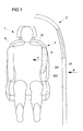
- Fig. 1 shows a vehicle seat assembly 1 mounted in a vehicle 2.
- the vehicle seat assembly 1 comprises a vehicle seat 3, which has an inflatable element 4 arranged in the region of its backrest 31.
- the inflatable element 4 is inflated when a crash sensor of the vehicle detects a collision on a side structure 21 (vehicle longitudinal side) of the vehicle.
- the force acting on the side structure due to the collision is indicated by the arrow K.
- the inflatable element 4 is designed and arranged such that, after being activated, it expands predominantly in the direction of a vehicle occupant 5 located on the seat and thus exerts a force F on the vehicle occupant 5 during expansion.
- the force F experienced by the vehicle occupant by the expanding inflatable element 4 moves it away from the side structure 21 and thus away from the collision location, thereby providing the absorption path available to energy of a vehicle longitudinal side structure 21, which intrudes under the action of the collision force K in the vehicle interior to dissipate.
- the inflatable element 4 is arranged on the vehicle seat such that, when inflated, it largely extends between a side 312 of the vehicle seat 3 which faces the vehicle longitudinal side 21 adjacent to the seat 3 and the vehicle occupant 5.
- a conventional side airbag extends in the inflated state in the space between the side 312 and the vehicle longitudinal side 21st
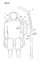
- Fig. 2 shows in a modification of the example not according to the invention Fig. 1 a vehicle seat assembly, which also has a conventional side airbag 6 in addition to the inflatable element 4.
- the vehicle occupant is moved away by the expanding inflatable element 4 from the side structure 21, which is affected by a collision.
- the absorption of energy of a structure intruding due to the collision is supported by the side gas bag 6 extending in the inflated state between the vehicle seat 3 and the vehicle longitudinal side 21.
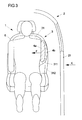
- FIG. 3 Another variation of the example of Fig. 1 shows Fig. 3 , Here are two inflatable elements 4a, 4b arranged transversely to the vehicle longitudinal axis side by side, each exerting a force on the vehicle occupant 5, when they expand.
- the force of the outer (ie closer to the vehicle longitudinal side 21) arranged element 4b is transmitted predominantly indirectly via the inner inflatable element 4a on the vehicle occupants.
- the inflatable elements 4a, 4b are in particular arranged so that in the inflated state each extend largely between the side 312 of the vehicle seat on the vehicle occupant 5, ie they do not extend or only with a small proportion between the vehicle seat 3 (ie its side 312 ) and the vehicle longitudinal side 21.
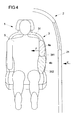
- Fig. 4 shows a further modification of the example of Fig. 1 according to which two inflatable elements 4a, 4b are arranged one above the other in the vehicle height direction. With this arrangement, it is possible to act on a larger body portion of the vehicle occupant 5.
- the upper inflatable element 4 a is arranged in the shoulder region of the vehicle occupant, while the lower inflatable element 4 b extends from a rib area to a pelvic area of the vehicle occupant 5.
- FIGS. 2 to 4 also be combined with each other.
- several elements in vehicle height direction one above the other and simultaneously several elements in the vehicle transverse direction may be arranged side by side.
- a conventional side airbag, as in Fig. 2 be shown provided.
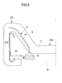
- Fig. 5 shows a horizontal section through a vehicle seat assembly not according to the invention in the amount of a backrest of the vehicle seat of the vehicle seat assembly.
- the backrest 31 has a side wall 311 which delimits a central part 314 of the backrest 31.
- a frame 313 is arranged, which stabilizes the backrest.
- the frame 313 is at least partially surrounded by a padding 7, which also forms a portion of the vehicle seat, which is to be located on the seat occupant (not shown).
- the padding 7 is surrounded by a cover 8, which forms an outer side of the vehicle seat.
- the padding 7 is z. B. formed by a foam-like material.
- an inflatable element 4 is arranged in the padding 7, an inflatable element 4 is arranged.
- the inflatable element has a wrapping material different from the material of the padding 7, which delimits an inflatable chamber 41.
- the shell material consists of a textile fabric, such as a conventional airbag material.
- the inflatable element 4 does not have a separate wrapping material, but the material of the padding 7 directly limits the inflatable chamber 41.
- the inflatable element is thus formed as a stretchable hollow space in the padding 7.
- the inflatable element 4 integrated in the padding 7 is inflated via means for inflating it in the form of a gas generator 9 (eg a micro gas generator).
- the gas generator 9 is integrated into the backrest 31 of the vehicle seat and attached via a holder 91, which may be fixed in particular to the frame 313.
- Fig. 6 shows the inflatable element 4 in inflated or at least partially inflated state.
- the inflatable element 4 is arranged and arranged to extend substantially in the direction of a vehicle occupant (not shown) located on a vehicle seat, thus exerting, via padding 7, a force on the vehicle occupant to move the vehicle away from a collision location.
- the material of the padding is designed correspondingly stretchable, so that the inflatable element in its interior can expand substantially unhindered in the direction of the vehicle occupant.
- the padding 7 is such that it at least partially ruptures by the expansion of the inflatable element 4, and thus hampers the expansion of the inflatable element and the power transmission to the vehicle occupant as little as possible.
- the padding is designed so that it tears together with the cover 8 in two parts 7a, 7b.
- the vehicle occupant-facing part 7b is moved toward the vehicle occupant by the expanding inflatable member, so that a force is transmitted from the expanding inflatable member via the portion 7b of the pad 7 to the vehicle occupant.
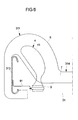
- Fig. 8 shows a section through the backrest portion of a vehicle seat of a vehicle seat assembly according to the invention.
- the inflatable element 4 is disposed between the padding 7 and the cover 8.
- an enveloping material which delimits the inflatable chamber 41 of the element 4 extends between the padding 7 and the cover 8 (see section 8A).
- the inflatable element 4 does not have any wrapping material other than the cover or upholstery, but the inflatable element is formed directly by the upholstery and / or padding of the vehicle seat, i. the chamber 41 of the inflatable element is bounded by the cover 8 and / or the padding 7.
- the chamber 41 is separated in this variant by seams that define the reference to the padding.
- the inflatable element Indicates the inflatable element as in Fig. 8 a separate shell material, this can be fixed to the cover 7 and / or the padding.
- This is in sections B and C according to which the covering material 42 of the inflatable element 4 are fastened to the cover 8 or to the padding 7 via fastening means 45 (eg adhesive or a seam).
- the fastening means 45 also serve, in particular, to hold the inflatable element 4 in position upon impact of the vehicle occupant or of a vehicle structure (intruding, for example, in the vehicle interior) and / or to divert a force which acts on the inflatable element.
- Fig. 9 shows an arranged between the padding 7 and the seat cover 8 inflatable element 4 in at least partially inflated state.
- the seat cover 8 is formed so stretchable in this example that it impedes the expansion of the inflatable element as little as possible.
- the seat cover is torn by the expansion of the inflatable element, so that the inflatable element can expand unhindered.
- weakenings eg in the form of a perforation or a tear seam
- the vehicle seat assembly in this embodiment also has fastening means in the form of a band 100, via which a portion of the wrapping material 42 of the inflatable element is connected to a part 200 of the vehicle seat.
- the band 100 serves to influence the direction of expansion of the inflatable element, i. H. to help the inflatable element expand predominantly toward the vehicle occupant.
- the belt 100 may be configured and arranged to hold the inflatable element in position upon impact of the vehicle occupant and / or vehicle structure.
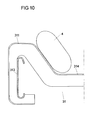
- Fig. 10 relates to a further variant of a non-inventive vehicle seat assembly, wherein again a sectional view through a backrest 31 of the vehicle seat of the vehicle seat assembly is shown.
- the inflatable element 4 is arranged in this variant from the outside to the backrest 31 (more precisely on the side cheek 311) and z. B. connected to the cover 8 and / or the padding 7 of the backrest 31.
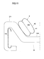
- Fig. 11 shows a development of the variant of Fig. 10 , wherein in the interior, ie in the chamber 41, of the inflatable element 4, a connecting element in the form of a tether 300 is arranged.
- the tether 300 connects portions of the inner surface of the wrapping material 42 to each other, so that the inflatable element 4 has a constriction in the inflated state.
- the tether 300 serves in particular to influence the direction of expansion of the inflatable element, in particular so that the inflatable element expands substantially in the direction of the vehicle occupant.
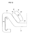
- Fig. 12 relates to a further modification of the variant of Fig. 10 in which two inflatable elements 4a, 4b are provided, each of which is designed as a chamber of a multi-chamber element 40.
- the multi-chamber element 40 has an enveloping material 402 which delimits the two chambers 4a and 4b.
- the two chambers are separated from one another by a separating element 403, whereby the separating element 300 passes through the interior of the wrapping material 402.
- the separating element 403 has an opening, so that an overflow of gas from one inflatable element into the other is possible.
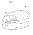
- Fig. 13 is a perspective view of a multi-chamber element 40, in which inflatable elements 4a, 4b are formed in the form of chambers. The chambers are separated by a partition 403.
- FIG. 13 Another embodiment of two inflatable elements is in Fig. 13 shown. Thereafter, two separately manufactured inflatable elements 4a, 4b abut one another in sections with their outer sides and are connected to one another via a connection 400 (eg in the form of a seam).
- a connection 400 eg in the form of a seam
- FIG. 15 shows a non-inventive airbag assembly with a gas bag 10, which is disposed on a z along the vertical vehicle axis z extending portion 22 of a body 2100 of a vehicle seat 20, wherein the main body 2100 is a seat frame of the vehicle seat 20 and at that area 22 um a portion of a back frame 23 of the vehicle seat 20, which is a part of the seat frame 2100.
- the back frame 23 forms a skeleton or a body of two back cheeks 25 of the vehicle seat 20, which protrude along the vehicle longitudinal axis x of a backrest 26 which extends in the zy plane, wherein the backrest 26 is usually pivotable about an axis extending along the vehicle transverse axis y axis (adjustable) is.
- the present considered backrest cheek 25 offers a occupant occupying the vehicle seat hold along the vehicle transverse axis y and is arranged adjacent to a lateral vehicle body.
- the vehicle seat 20 can also be a motor vehicle rear bench.
- the gas bag 10 is composed at least of a first airbag part 1000 and a second airbag part 101, which are interconnected along their outer peripheral edges, for example by means of a seam.
- the two airbag parts 1000, 101 can be separated be formed or integrally formed on each other. In the latter case, the two airbag parts 1000, 101 are folded along one axis and the superimposed edge portions of those airbag parts 1000, 101 connected to each other (so-called butterfly blank).
- the gas bag 10 thus formed is wrapped around the said area 22 of the main body 2100-here a back frame portion 22-so that the back frame portion 22 is arranged between the gas bag 10 along the vehicle transverse axis y.
- the gas bag 10 is divided into a first portion 110 and a second portion 111 connected thereto, wherein the transition from the first to the second portion 110, 111 along an end face 22a of the back frame portion 22, which faces the vehicle front.
- the first section 110 of the airbag 10 is arranged on an inner side 22b of the backrest frame section 22, which faces a occupant occupying the vehicle seat 20 as intended.
- the second section 111 of the airbag 10 is arranged on an outer side 22c of the backrest frame section 22 facing away from the inner side 22b.
- a gas generator 30 arranged in the first section 110 is provided, ie the gas generator 30 is arranged in a region of an interior of the airbag 10 defined by the section 110, the gas generator 30 being arranged on the inside 22b along the backrest frame section 22 extends and is secured to the said inner side 22b of the back frame portion 22.
- the gas bag 10 is also fastened to the back frame section 22 via the gas generator 30, for example by the gas generator 30 pressing a region of the gas bag 10 against the back frame section 22.
- Said back frame portion 22 is surrounded together with the gas bag 10 and inflator 30 secured thereto by a portion 4000 of a seat foam (seat foam portion 4000) of the vehicle seat 20, that seat foam forming an outer cover of the main body 2100 of the vehicle seat 20, which may be related to a final seat cover , That is, the seat foam portion 4000 has a recess 450, in which the airbag module (gas generator 30 and airbag 10) is arranged.
- the gas bag 10 can expand in the seat foam portion 4000 during inflation, is on one of the end face 22a of the back frame portion 22 facing wall 46th the recess 450 of the seat foam portion 4000 a recess 50 provided in the form of a groove which extends along said end face 22a.
- the seat foam portion 4000 can thus expand in cross-section - with unfolding of that groove 50 - so that the recess 450 of the seat foam portion 4000 can also accommodate an enlarged as a result of inflation gas bag volume.
- the airbag 10 is divided into the two sections 110, 111 as described above, the occupant to be protected is pushed away from the inside 22b of the back frame section 22 by the airbag 10 (due to the expansion of the seat foam section 4000), so that the occupant at the outside of the Lehmen frame section 22 directed action on the vehicle body can be transported away from the danger zone.
- a connection 60 between an edge region 111a of the second section 111 of the airbag 10 and the outer side 22c of the back frame section due to the pressure prevailing in the airbag pressure can be released, so that the airbag deploys in the xz plane.
- the gas bag may pierce a predetermined breaking point 47 of the seat foam section 4000 (cf. FIG. 20 ).
- FIG. 16 shows a modification of the in FIG. 15 shown gas bag assembly, in which the second portion 111 of the airbag 10 in contrast to FIG. 15 is not disposed on the outer side 22c of the back frame portion 22, but along the vehicle transverse axis y between the first portion 110 and the back frame portion 22.
- Both in the FIG. 15 as well as at the FIG. 16 Both sections 110, 111 preferably extend along the xz plane prior to inflation and preferably have the same area.
- the edge portion 111 a of the second portion via the connection 60 is not connected to the outside 22 b of the back frame portion, but with the inside 22 b of the back frame portion.
- FIG. 17 shows in connection with the FIG. 18 with reference to a schematic, sectional sectional view of a modification of the in FIGS. 15 and 16 shown gas bag assembly.
- an additional abutment member 70 is provided, with a first part 71 which extends flat in the xz plane and over the abutment member 70 is connected to the back frame portion 22. From a vehicle front facing, along the vertical axis of the vehicle extending edge 72 of the abutment member 70 is a second part 73 of the abutment member 70 in the direction of the occupant to be protected, which is integrally formed on the first part 71 and inclined to the xz plane along the vertical vehicle axis z extends, so that said edge 72 is formed at an acute angle with respect to the xy plane.
- the above-mentioned planes are spanned by the vehicle longitudinal axis x and the vertical vehicle axis z or by the vehicle longitudinal axis x and the vehicle transverse axis y. According to the FIG. 18 If said edge 72 can also be formed at an obtuse angle.
- the abutment element 70 can form a carrier of an airbag module, that is, both the gas bag 10 and the gas generator 30 and possibly the seat foam section 4000 can be fastened to the abutment element (carrier) 70.
- the entire airbag module is then fixed to the backrest frame section 22 or the region 22 via the abutment element.
- the gas bag 10 can be supported during inflation and thus displace the occupant effectively obliquely forwards towards the vehicle front (due to the inclination of the second part 73, there is a component of movement along the vehicle transverse axis y) Interior).
- the first part 71 of the abutment element 70 is located at a closer to the vehicle front, along the vertical vehicle axis z extending edge region 74 of the abutment member 70, so that the abutment member 70 engages around the end face 22a of the back frame portion 22 in cross-section, ie, the said end face 22a is arranged along the vehicle transverse axis y between the first and the second part 71, 73.
- the gas generator 30 may also be arranged along the vehicle transverse axis y between the first and the second part 71, 73 of the abutment element 70. In this case, the gas generator 30 may be fastened to the abutment element 70 and / or to the backrest frame section 22. Alternatively, the gas generator is arranged on the outer side 22c of the back frame section 22 and fastened there to the back frame section 22.
- the gas bag 10 extends before inflating along a surface 73 a facing the occupant of the second part 73 of the abutment element 70 and is thereby turned over so that the two sections 110, 111 of the airbag 10 are stacked and parallel are arranged to said surface 73a.
- the second section 111 is preferably arranged along a normal N to the surface 73a between the said surface 73a and the first section 111. That is to say, the gas bag rests against the surface 73a of the abutment element 70 via the second section 111.
- a supply line 80 is provided, which is preferably made of an airbag material.
- the supply line 80 can be discharged from the gas generator 30 into the first section or the second section.
- the feed line 80 can be guided through a passage opening 90 of the first part 71 of the abutment element 70 and possibly through a passage opening 90 of the second part 72. It is also possible to feed the feed line 80 around the abutment element 70 around set. In a gas generator 30 fixed to the abutment element 70, the feed line 80 can be guided through a through-opening 90 of the second part 73 or can be placed around the second part 73.
- a seat foam section 4000 surrounding the airbag module (gas bag, gas generator, supply line and abutment element) is provided (cf. FIGS. 15 and 16 ).
- the additional abutment member 70 is not as in the FIGS. 17 and 18 formed by a preferably made of metal element, but consists of a foam, which is, however, harder than a surrounding seat foam of the vehicle seat 20 is formed.
- the airbag module gas bag, gas generator
- the gas generator 30 is preferably fastened to the edge region 73 of the backrest frame section 22, in particular with a screw connection which is screwed from the inside 22b of the back frame section 22, wherein the gas generator 30 itself is arranged on the front side 22a of the back frame section 22.
- the abutment element 70 consisting of foam has at least the first part 73, via which the gas bag 10 can support itself as it is inflated, as described above.
- FIG. 20 shows a modification of the in FIG. 17 shown gas bag assembly, in contrast to FIG. 17 the abutment element 70 forms a housing for the gas generator 30, which is fastened via the abutment element 70 on the back frame section 22, wherein the gas generator is arranged on the front side 22a of the backrest frame section 22 and is surrounded in the xy plane by the abutment element 70 at least from three sides.
- the abutment element 70 is correspondingly curved in the said cross-sectional plane, so that it can embrace the said end face 22a with the gas generator 30 attached thereto.
- the abutment element 70 has two edge regions 74a, 74b extending along the vertical vehicle axis z, wherein the abutment element 70 is connected to the outside 22c of the back frame section 22 via a first edge region 74a and to the inside 22b of the back frame section 22 via the second edge region 74b.
- the abutment element 70 is bolted via the first edge region 74a from the outside 22c forth with the back frame portion 22 (via a screw 77, which is introduced from the outside 22c of the back frame portion 22 forth in a corresponding through hole of the back frame portion 22) and with the second edge region 74b suspended from the inside 22b forth in the back frame portion 22, wherein a portion of the second edge portion 74b engages behind a portion of the back frame portion 22.
- the gas bag 10 itself is according to the FIG. 15 wrapped around the abutment member 70 so that the first portion 110 rests against an occupant facing inner side 70a of the abutment member 70 and the second portion on an inner side 70a facing away from the outer side 70b of the abutment member 70th
- the gas bag 10 is preferably suspended on the inner side 70a of the abutment element 70 and fixed on the outer side 70b of the abutment element 70 via the said screw 77 on the abutment element 70.
- This connection of the second section 111 of the airbag 10 may be designed to be released during inflation of the airbag 10, so that the second section 111 may possibly unfold along the x-z plane.
- the abutment element 70 preferably forms a support of an airbag module which carries the gas bag, the gas generator and possibly the section 4000 of the seat foam, ie these components are fastened to the carrier and are preferably conveyed via this carrier to the back frame section 22 or area 22 established.
- FIG. 21 shows a variant in which the main body 2100 of the vehicle seat 20 is formed by a seat shell, which is covered on a vehicle front side facing by a seat foam.
- that region 22 of the main body 2100 is replaced by a along the vertical vehicle axis z extended portion of the seat 2100 formed, which forms part of a backbone for a backrest cheek 25 of the vehicle seat 20.
- This has an inner side 22a, which faces the occupant to be protected and extends along the xz plane, on which the abutment element 70 formed as a housing is fixed.
- the gas bag 10 folded in the manner of FIG.
- the abutment element 70 embodied as a housing is covered by a seat foam section 4000 on a side facing away from the inside 22a.
- the abutment member 70 forms a carrier of the airbag module.
- FIG. 22 shows an alternative arrangement or convolution of the airbag 10.
- the gas generator 30 is disposed on the outer side 22c of the back frame portion 22 and connected by a supply line 80 to the airbag 10, which is arranged on the inner side 22b of the back frame portion 22, wherein that feed line 80th is guided through a passage opening 90 of the back frame portion 22 to the airbag 10 and there opens centrally into the first portion 110 of the airbag 10, and off a circumferential seam 201 through which a first airbag portion 2001 of the first portion 110 of the airbag 10 with a peripheral region 202a of circulating second airbag part 202 is connected.
- that first airbag part 2001 extends flat along the inner side 22b of the backrest frame section 22.
- FIG. 23 shows a variant of a non-inventive airbag assembly or a non-inventive airbag module, wherein the airbag 10 in contrast to the FIGS. 15 to 22 is not covered by a seat foam portion 4000, but is spread over this area, said seat foam portion 4000 surrounds the back frame portion 22 in cross section. Accordingly, the gas bag 10 is wrapped around the back frame portion 22, so that the first portion 110 of the airbag 10 on the inside 22 a
- the gas generator 30 is embedded on the inside 22b of the back frame section 22 in the seat foam section 4000 and can be foamed in particular in those seat foam section 4000. As a result, the gas generator 30 is fixed relative to the backrest frame section 22.
- the gas generator 30 may be arranged in the first section 110. Alternatively, a supply line 80 may be provided, via which the gas generator 30 may be connected to the first section 110.
- FIG. 24 shows a modification of the in FIG. 22 shown gas bag assembly, in which the gas bag 10 in contrast to FIG. 22 has no bellows shape, but is divided into three sections 110, 111 and 112, wherein the first portion 110, in which the feed line 80 of the gas generator 30 opens, along the inner side 22b of the back frame portion 22 is extended and along the end face 22a in the second section 111, which extends flat along the outer side 22c.
- the first and second sections 110, 111 of the airbag 10 are therefore placed around the backrest frame section 22.
- the third section 112 of the airbag 10, which integrally adjoins the second section 111, is folded over onto the first and second sections 110, 111 so that it covers the first and second sections 110, 111.
- the gas bag 10 is according to FIG. 25 which is a modification of the in the FIG. 24 shown gas bag assembly, only according to FIG. 15 divided into two sections 110, 111, wherein the gas bag 24 according to FIG. 25 having a butterfly cut. That is, the airbag 10 has a first airbag part 3000 and a second airbag part 301, which are integrally formed along a folding axis 302 and are folded along this folding axis 302 to each other.
- the outer edge sections of the two airbag parts 3000, 301 which come to lie on top of each other are connected to one another by means of a connection 305, in particular in the form of a seam.
- the folding axis 302 runs along the vertical vehicle axis z along the inside 22b of the backrest frame section 22 and lies opposite the gas generator 30 along the vehicle transverse axis y.
- FIG. 26 shows a modification of the in FIG. 16 shown gas bag assembly in which the gas bag10 is taken, so that the first and the second portion 110, 111 respectively with their edge portions 110a, 111b, which are along the vertical vehicle axis z are adjacent to the end face 22a of the back frame portion 22 are arranged.
- the gas bag 10 is further foamed into the surrounding seat foam portion 4000, wherein on the gas bag 10, a plurality of openings 4001 is formed through which foam can penetrate during foaming in an inner space defined by the gas bag 10. As a result, the airbag 10 is anchored in the seat foam.
- FIG. 27 Such openings 4001 are provided, in contrast to FIG. 26 two separate airbags 10a and 10b are provided which extend in the non-inflated state in each case flat along the inner side 22b of the back frame portion 22 and are arranged congruently one above the other.
- FIG. 31 shows a modification of the in FIG. 26 shown gas bag assembly in which the gas bag 10 in contrast to FIG. 26 according to the FIG. 16 is formed and in addition the basis of the FIG. 26 having openings 4001 described.
- FIGS. 26, 27 and 31 can the superposed airbag parts 500, 501 of the gas bags 10, 10a, 10b shown there also according to FIG. 33 are glued together and with the surrounding seat foam portion 4000 to permanently position the gas bags 10, 10a, 10b with respect to the seat foam, which bonds dissolve when the respective gas bags 10, 10a, 10b are inflated.
- the two gas bags 10a and 10b can be made according to FIG. 28 can also be arranged in a recess 450 of the seat foam section 4000, wherein a wall 4100 of the recess 450 may have an opening to the occupant, so that the two gas bags 10a, 10b covering wall 4100 when inflating the airbags 10a, 10b through the airbags 10a, 10b can be deflected in the direction of the occupant.
- wall 4100 may be wrapped around the airbag (s) 10, 10a, 10b, or around the back frame section 22, such that a relatively large portion of the seat foam section 4000 is hinged toward the occupant.
- This hinged wall 4100 shields the occupants in a side crash additionally.
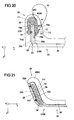
- FIG. 30 can the seat foam portion 4000 according to FIG. 29 as well as all the above-described seat foam sections 4000 on the airbag module (comprising gas bag 10, 10a, 10b, gas generator 30 and possibly abutment element 70 or a carrier or a housing of the airbag module) prefixed or fastened, wherein those seat foam section 4000 during assembly of the airbag module at the airbag modules described above preferably front side, ie, takes place from the end face 22a of the back frame portion 22 ago, is arranged in a provided on the seat foam of the vehicle seat recess.
- FIG. 32 shows this with reference to a schematic, sectioned section through a vehicle seat 20 along the yz plane.
- the airbag module according to FIG. 30 preferably has the seat foam section 4000, which envelops the gas bag 10 and is preferably preformed such that the seat foam section is curved and can embrace the back frame section 22 in such a way that the gas bag 10 extending in the section 4000 corresponds to FIG FIG. 15 is wrapped around the back frame portion 22 when the airbag module is mounted on the vehicle seat 20.
- a supply line 80 along the vehicle longitudinal axis x out which connects the airbag 10 (first portion 110) with the gas generator 30 which is mounted together with the seat foam portion 4000 and the airbag 10 to a support 600, via which the Airbag module on the back frame portion 22 is fixed.
- the gas generator 30 is positioned on the inner side 22b of the back frame section 22.
- the carrier 600 may also be correspondingly FIG. 20 be formed as an abutment element.
Description
Die vorliegende Erfindung betrifft eine Fahrzeugsitzanordnung für ein Kraftfahrzeug gemäß Anspruch 1 sowie ein Verfahren zum Schützen eines Fahrzeuginsassen gemäß Anspruch 15.The present invention relates to a vehicle seat assembly for a motor vehicle according to
Es ist bekannt, in einen Fahrzeugsitz eines Kraftfahrzeuges einen Seitengassack zu integrieren, der sich bei einer Kollision des Fahrzeuges in den Raum zwischen dem Fahrzeugsitz und der Fahrzeugseitenstruktur hinein entfaltet.It is known to integrate in a vehicle seat of a motor vehicle, a side airbag, which unfolds in a collision of the vehicle in the space between the vehicle seat and the vehicle side structure.
Aus der
Zudem offenbart die gattungsbildende
Darüber hinaus offenbart die
Das von der Erfindung zu lösende Problem besteht darin, einen auf einfache Weise realisierbaren und effizienten Schutz für einen auf einem Fahrzeugsitz befindlichen Fahrzeuginsassen zu schaffen.The problem to be solved by the invention is to provide an easily realizable and efficient protection for a vehicle occupant located on a vehicle seat.
Dieses Problem wird durch die Fahrzeugsitzanordnung gemäß Anspruch 1 sowie durch das Verfahren gemäß Anspruch 15 gelöst. Weiterbildungen der Erfindung sind in den abhängigen Ansprüchen angegeben.This problem is solved by the vehicle seat assembly according to
Danach wird eine Fahrzeugsitzanordnung für ein Kraftfahrzeug bereitgestellt, mit
- einem Fahrzeugsitz, der mindestens ein zum Schutz eines auf dem Fahrzeugsitz befindlichen Fahrzeuginsassen aufblasbares Element aufweist, wobei
- das aufblasbare Element so ausgebildet und angeordnet ist, dass es sich überwiegend in Richtung auf den Fahrzeuginsassen ausdehnt, wenn es aufgeblasen wird, und wobei
- das aufblasbare Element ungefaltet oder mit nur einer Falte oder einer Stülpung versehen in eine Rückenlehne des Fahrzeugsitzes integriert ist, wobei
- das aufblasbare Element zwischen einer Polsterung des Fahrzeugsitzes und einem Bezug des Fahrzeugsitzes angeordnet ist.
- a vehicle seat having at least one inflatable element for protecting a vehicle occupant located on the vehicle seat, wherein
- the inflatable element is configured and arranged to expand predominantly toward the vehicle occupant when inflated, and wherein
- the inflatable element unfolded or provided with only one fold or an inverted piece is integrated in a backrest of the vehicle seat, wherein
- the inflatable element is disposed between a padding of the vehicle seat and a reference of the vehicle seat.
Das aufblasbare Element weist insbesondere ein Hüllmaterial auf, das eine aufblasbare Kammer begrenzt. Das Hüllmaterial ist z. B. aus einem herkömmlichen Gassackgewebe gebildet, wobei zwei oder mehr Lagen des Gassackmaterials, insbesondere über eine Randnaht, miteinander verbunden sein können. Als Hüllmaterial kommen jedoch auch andere (z.B. elastische) Materialien in Frage.In particular, the inflatable element comprises a wrapping material that defines an inflatable chamber. The wrapping material is z. B. formed from a conventional airbag fabric, wherein two or more layers of the airbag material, in particular via an edge seam, may be connected to each other. However, other (e.g., elastic) materials may be considered as the shell material.
Des Weiteren kann die Kammer des aufblasbaren Elementes auch unmittelbar durch Strukturen des Fahrzeugsitzes selber begrenzt sein, so dass das aufblasbare Element kein gesondertes Hüllmaterial aufweist. Auf diese Ausgestaltung wird weiter unten genauer eingegangen.Furthermore, the chamber of the inflatable element may also be directly limited by structures of the vehicle seat itself, so that the inflatable element does not have a separate covering material. This embodiment will be discussed in more detail below.
In einer Variante erstreckt sich das aufblasbare Element im nicht aufgeblasenen Zustand flach. Insbesondere weist das gar nicht oder einfach gefaltete bzw. gestülpte aufblasbare Element ein Hüllmaterial auf, das aus einer oder aus mehreren Materiallagen besteht. Zum Versehen des aufblasbaren Elementes mit einer "Stülpung" wird ein Abschnitt des unaufgeblasenen aufblasbaren Elementes, d.h. insbesondere ein Abschnitt des Hüllmaterials, in das Innere des aufblasbaren Elementes hineingestülpt.In one variant, the inflatable element extends flat when not inflated. In particular, the inflatable element, which is not folded at all or simply folded, has an enveloping material that consists of one or more layers of material. To provide the inflatable element with a "protuberance", a portion of the deflated inflatable element, i. in particular, a portion of the wrapping material, inverted into the interior of the inflatable element.
Dass das aufblasbare Element ungefaltet bzw. nur einfach gefaltet sein soll, bezieht auf das fertiggestellte aufblasbare Element. Das aufblasbare Element kann jedoch durchaus durch Umfalten eines Hüllmaterialzuschnitts hergestellt werden und zur Unterbringung in dem Fahrzeugsitz noch einmal gefaltet werden, z.B. derart, dass nach der Faltung zwei Abschnitte der Außenseite des aufblasbaren Elementes aneinander liegen.That the inflatable element should be unfolded or simply folded, refers to the finished inflatable element. However, the inflatable element can certainly be made by folding over a Hüllmaterialzuschnitts and be folded again for placement in the vehicle seat, for example, such that after folding two sections of the outside of the inflatable element to each other.
Des Weiteren ist das aufblasbare Element in einem Beispiel der Erfindung so ausgebildet und angeordnet, dass es sich im aufgeblasenen Zustand größtenteils zwischen einer Seite des eingebauten Fahrzeugsitzes, die der dem Fahrzeugsitz näheren Fahrzeuglängsseite (der beiden, einander gegenüberliegenden Fahrzeuglängsseiten des Fahrzeugs) zugewandt ist und dem Fahrzeuginsassen erstreckt. D. h. das aufblasbare Element erstreckt sich nicht wie ein konventioneller Seitengassack überwiegend zwischen dem Fahrzeugsitz und der Fahrzeuglängsseite, sondern in einem Bereich, der einerseits durch eine Ebene, in der sich die zur Fahrzeuglängsseite weisende Seite des Fahrzeugsitzes erstreckt und andererseits durch den Fahrzeuginsassen begrenzt ist. Das aufblasbare Element ragt somit im aufgeblasenen Zustand kaum oder gar nicht in den Raum zwischen dem Fahrzeugsitz und der Fahrzeuglängsseite hinein.Furthermore, in one example of the invention, the inflatable element is designed and arranged such that, when inflated, it largely faces between a side of the installed vehicle seat which faces the vehicle longitudinal side closer to the vehicle seat (the two vehicle longitudinal sides facing one another) and Vehicle occupants extends. Ie. The inflatable element does not extend like a conventional side airbag predominantly between the vehicle seat and the vehicle longitudinal side, but in a region which is bounded on the one hand by a plane in which extends the vehicle longitudinal side facing side of the vehicle seat and on the other hand by the vehicle occupant. The inflatable element thus protrudes in the inflated state hardly or not at all in the space between the vehicle seat and the vehicle longitudinal side.
Zum Aufblasen des aufblasbaren Elementes sind insbesondere Mittel vorgesehen, die das aufblasbare Element ab Beginn einer Kollision des Kraftfahrzeuges aufblasen. Die Mittel werden durch ein Steuersignal einer Crash-Sensorik des Fahrzeuges aktiviert; insbesondere, wenn diese eine Seitenkollision des Fahrzeugs detektiert. Somit hat das aufblasbare Element die Funktion, den Fahrzeuginsassen im Falle einer sich tatsächlich ereignenden Kollision zu schützen.For inflating the inflatable element in particular means are provided which inflate the inflatable element from the beginning of a collision of the motor vehicle. The means are activated by a control signal of a crash sensor of the vehicle; in particular, if it detects a side collision of the vehicle. Thus, the inflatable element has the function of protecting the vehicle occupant in the event of a collision actually occurring.
Das aufblasbare Element ist in einer anderen Ausgestaltung der Erfindung so ausgebildet und angeordnet, dass es, während es sich (impulsartig) ausdehnt, eine Kraft (bzw. einen Impuls) auf den Fahrzeuginsassen ausübt, die ihn von einer Fahrzeugseitenstruktur (Fahrzeuglängsseite) weg bewegt. Insbesondere wird der Fahrzeuginsasse durch das sich aufblasende aufblasbare Element von einer Kollisionsstelle des Fahrzeugs, insbesondere von einem Abschnitt der dem Fahrzeugsitz nächstliegenden Fahrzeuglängsseite, der von einer Kollision des Fahrzeugs betroffen ist, weg bewegt. Das Aufblasen des aufblasbaren Elementes erfolgt insbesondere so, dass die Kraft auf den Fahrzeuginsassen nicht so groß wird, dass ein Verletzungsrisiko besteht.In another aspect of the invention, the inflatable element is configured and arranged to exert a force (or impulse) on the vehicle occupant as it extends (impulsively) away from a vehicle side structure (vehicle longitudinal side). In particular, the vehicle occupant is moved away from a collision point of the vehicle by the inflatable inflatable element, in particular from a section of the vehicle longitudinal side closest to the vehicle seat, which is affected by a collision of the vehicle. The inflation of the inflatable element is in particular such that the force on the vehicle occupant is not so great that there is a risk of injury.
Durch das Bewegen des Fahrzeuginsassen von der Kollisionsstelle weg wird einer Bewegung des Fahrzeuginsassen aufgrund seiner Massenträgheit auf die Kollisionsstelle zu entgegengewirkt. Zudem vergrößert sich der zwischen dem Fahrzeuginsassen und der Kollisionsstelle vorhandene Weg (Absorptionsweg), so dass mehr Energie einer infolge der Kollision in den Fahrzeuginnenraum intrudierenden Struktur des Fahrzeugs (insbesondere der Fahrzeuglängsseite) dissipiert wird, bevor die Struktur auf den Fahrzeuginsassen auftrifft, als bei Verwendung nur eines konventionellen Seitengassacks.By moving the vehicle occupant away from the collision location, a movement of the vehicle occupant due to its inertia on the collision point is counteracted. In addition, the existing between the vehicle occupant and the collision location path (absorption path) increases, so that more energy of an intruding due to the collision in the vehicle interior structure of the vehicle (especially the vehicle longitudinal side) is dissipated before the structure impinges on the vehicle occupant, as in use just a conventional side airbag.
Insbesondere übt das aufblasbare Element somit die Kraft auf den Fahrzeuginsassen, die ihn von der Kollisionsstelle weg bewegt, aus, bevor es in direkten Kontakt mit einem in den Fahrzeuginnenraum intrudierenden Abschnitt der Fahrzeugseitenstruktur kommt. Das bedeutet, dass das Wegbewegen des Fahrzeuginsassen von der Kollisionsstelle unabhängig von der Bewegung der Kollisionsstelle auf den Fahrzeuginsassen zu ist, d.h. der Fahrzeuginsasse wird nicht aufgrund eines Aufpralls der intrudierenden Fahrzeugseitenstruktur auf das aufblasbare Element bewegt. Erst im weiteren Verlauf der Kollision, d. h. bei fortgeschrittenem Eindringen der Fahrzeugseitenstruktur in den Innenraum, kann es zu einem mittelbaren oder unmittelbaren Aufprall der intrudierenden Struktur mit dem Fahrzeuginsassen kommen, wobei die Stärke des Aufpralls durch den verlängerten Absorptionsweg vermindert ist.In particular, the inflatable element thus exerts the force on the vehicle occupant moving it away from the collision location before coming into direct contact with a section of the vehicle side structure intruding into the vehicle interior. That is, moving the vehicle occupant away from the collision location is independent of the movement of the collision location toward the vehicle occupant, i. the vehicle occupant is not moved onto the inflatable element due to an impact of the intruding vehicle side structure. Only in the further course of the collision, d. H. if the vehicle side structure has penetrated into the interior in an advanced manner, an indirect or direct impact of the intruding structure with the vehicle occupant can occur, whereby the magnitude of the impact due to the extended absorption path is reduced.
Das aufblasbare Element ist in einer Variante der Erfindung so ausgebildet, und angeordnet, dass es überwiegend auf den Rippenbereich des Fahrzeuginsassen einwirkt. In einer anderen Ausgestaltung wird die Kraft vorwiegend im Bereich der Schulter und/oder des Beckens des Fahrzeuginsassen auf diesen übertragen.The inflatable element is formed in a variant of the invention, and arranged so that it acts predominantly on the rib area of the vehicle occupant. In another embodiment, the force is transmitted predominantly in the region of the shoulder and / or the pelvis of the vehicle occupant.
In einer anderen Weiterbildung der Erfindung weist die Fahrzeugsitzanordnung Mittel zum Dämpfen eines Aufpralls des Fahrzeuginsassen und/oder einer Fahrzeugstruktur auf das aufblasbare Element auf. Die Mittel umfassen insbesondere ein absorbierendes Element, das Energie der aufprallenden Struktur bzw. des aufprallenden Fahrzeuginsassen dissipiert. Beispielsweise umfassen die Mittel eine Stoßdämpferstruktur, die mit dem aufblasbaren Element gekoppelt ist, oder eine Abströmöffnung, aus der Gas aus dem aufblasbaren Element nach außen abströmen kann.In another development of the invention, the vehicle seat arrangement has means for damping an impact of the vehicle occupant and / or a vehicle structure on the inflatable element. In particular, the means comprise an absorbing element which dissipates energy of the impacting structure or vehicle occupant. For example, the means comprise a shock absorber structure, which is coupled to the inflatable element, or a discharge opening, from which gas can flow outward from the inflatable element.
Die Abströmöffnung ist beispielsweise permanent in einem Hüllenmaterial, das eine Kammer des aufblasbaren Elementes umgibt, vorhanden. In einer anderen Ausgestaltung ist die Abströmöffnung zu Beginn des Aufblasens des aufblasbaren Elementes verschlossen und wird erst zu einem vorgebbaren Zeitpunkt nach Beginn des Aufblasens geöffnet oder sie wird erst nach einer bestimmten Zeit in dem aufblasbaren Element gebildet. Es können selbstverständlich auch mehrere Abströmöffnungen vorhanden sein.For example, the discharge opening is permanently present in a casing material surrounding a chamber of the inflatable element. In another embodiment, the discharge opening is closed at the beginning of the inflation of the inflatable element and is opened only at a predeterminable time after the start of inflation or it is formed only after a certain time in the inflatable element. Of course, there may also be several outflow openings.
In einer Weiterbildung ist das aufblasbare Element ausgebildet, in einer ersten Phase des Ausdehnens die Kraft auf den Fahrzeuginsassen auszuüben, während die Mittel zum Dämpfen eines Aufpralls (des Fahrzeuginsassen und/oder einer intrudierenden Fahrzeugstruktur) während einer nachfolgenden, zweiten Phase des Ausdehnens des aufblasbaren Elementes aktiviert werden.In one embodiment, the inflatable element is configured to exert force on the vehicle occupant in a first phase of expansion, while the means for damping an impact (of the vehicle occupant and / or an intruding vehicle structure) during a subsequent, second phase of expansion of the inflatable element to be activated.
In dieser Weiterbildung erfolgt somit zuerst ein Aufblasen des aufblasbaren Elementes, ohne dass die Mittel zum Dämpfen des Aufpralls aktiviert sind. Dies ermöglicht insbesondere eine möglichst effiziente Kraftübertragung vom sich ausdehnenden aufblasbaren Element auf den Fahrzeuginsassen und somit ein möglichst wirksames Wegbewegen des Fahrzeuginsassen. Beispielsweise weisen die Mittel zum Dämpfen eines Aufpralls in dieser Variante der Erfindung eine Abströmöffnung des aufblasbaren Elementes auf, die erst nach einer bestimmten Zeit nach Beginn des Aufblasens des aufblasbaren Elementes freigegeben wird, damit sich das aufblasbare Element in der Anfangsphase möglichst rasch ausdehnt und einen möglichst großen Impuls auf den Fahrzeuginsassen ausübt.In this development, inflation of the inflatable element thus takes place first, without the means for damping the impact being activated. This allows in particular the most efficient transmission of power from the expanding inflatable element on the vehicle occupants and thus the most effective way moving the vehicle occupant. For example, the means for damping an impact in this variant of the invention on a discharge opening of the inflatable element, which is released after a certain time after the start of inflation of the inflatable element, so that the inflatable element in the initial phase expands as quickly as possible and as possible great impulse to the vehicle occupants.
Die Abströmöffnung kann z. B. passiv gesteuert sein, d. h. insbesondere einen Mechanismus umfassen, der die Ausdehnung des Gassacks nutzt, um die Abströmöffnung freizugeben. Dies kann beispielsweise ein Band sein, das an einem Hüllmaterial des aufblasbaren Elementes festgelegt ist und das mit einem Verschlussmechanismus der Abströmöffnung verbunden ist. Das Öffnen der Abströmöffnung kann auch aktiv erfolgen, insbesondere durch eine Verschlussvorrichtung, die auf ein Steuersignal einer Crash-Elektronik des Fahrzeugs reagiert und die Ausströmöffnung in Abhängigkeit von dem Steuersignal z. B. pyrotechnisch oder elektromechanisch freigibt.The discharge opening can, for. B. be controlled passively, d. H. in particular, comprise a mechanism which utilizes the expansion of the gas bag to release the discharge opening. This may for example be a band which is fixed to a shell material of the inflatable element and which is connected to a closure mechanism of the outflow opening. The opening of the discharge opening can also be active, in particular by a closure device which responds to a control signal of crash electronics of the vehicle and the outflow opening in response to the control signal z. B. pyrotechnic or electromechanical releases.
Es wird darauf hingewiesen, dass das aufblasbare Element und/oder die Mittel zum Aufblasen des aufblasbaren Elementes zwar insbesondere bei Beginn der Kollision aktiviert werden. Es kann jedoch auch vorgesehen sein, dass das Aufblasen des aufblasbaren Elementes bereits vor dem Beginn der eigentlichen Kollision initiiert wird, um den Fahrzeuginsassen möglichst weit von der Kollisionsstelle weg zu bewegen und einen möglichst großen Absorptionsweg zu schaffen. Das Auslösen des aufblasbaren Elementes kann somit bereits als Reaktion auf ein Steuersignal einer Pre-Crash-Elektronik des Fahrzeugs erfolgen.It should be noted that, although the inflatable element and / or the means for inflating the inflatable element are activated in particular at the beginning of the collision. However, it can also be provided that the inflation of the inflatable element is initiated even before the beginning of the actual collision in order to move the vehicle occupant as far away from the collision location as possible and to create the largest possible absorption path. The triggering of the inflatable element can thus already take place in response to a control signal of a pre-crash electronics of the vehicle.
In einer anderen Ausgestaltung der Erfindung ist das aufblasbare Element reversibel aufblasbar gestaltet, d. h. es kann auch zu Komfortzwecken (z.B. zur Veränderung der Form des Sitzes) aufgeblasen werden. Gleichzeitig sind die Mittel zum Aufblasen des aufblasbaren Elementes so ausgestaltet, dass sie ein wiederholtes Befüllen des aufblasbaren Elementes ermöglichen.In another embodiment of the invention, the inflatable element is reversibly inflatable, d. H. it may also be inflated for comfort purposes (e.g., to change the shape of the seat). At the same time, the means for inflating the inflatable element are configured to allow repeated inflation of the inflatable element.
Es versteht sich, dass der Fahrzeugsitz auch eine Mehrzahl aufblasbare Elemente aufweisen kann. Insbesondere können mehrere aufblasbare Elemente jeweils in Form einer Kammer eines Mehrkammerelementes ausgebildet sein. Die Kammern sind z. B. durch ein gemeinsames Hüllmaterial begrenzt und untereinander z. B. durch Nähte abgegrenzt, wobei nicht ausgeschlossen ist, dass die Kammern oder einige der Kammern in Strömungsverbindung miteinander stehen.It is understood that the vehicle seat may also have a plurality of inflatable elements. In particular, several inflatable elements may each be designed in the form of a chamber of a multi-chamber element. The chambers are z. B. by a common Covering limited and each other z. B. delimited by seams, wherein it is not excluded that the chambers or some of the chambers are in fluid communication with each other.
Das aufblasbare Element bzw. die mehreren aufblasbaren Elemente ist/sind darüber hinaus z. B. an oder in einer Seitenwange des Fahrzeugsitzes angeordnet, der dem auf dem Sitz befindlichen Fahrzeuginsassen zugewandt ist. Die Seitenwange begrenzt insbesondere ein Mittelteil einer Sitzfläche und/oder einer Rückenlehne des Fahrzeugsitzes. Es kann auch vorgesehen sein, dass an einander gegenüberliegenden Seitenwangen des Fahrzeugsitzes jeweils aufblasbare Elemente angeordnet sind.The inflatable element or the plurality of inflatable elements is / are beyond z. B. on or in a side cheek of the vehicle seat, which faces the vehicle occupant located on the seat. The side wall delimits in particular a middle part of a seat surface and / or a backrest of the vehicle seat. It can also be provided that in each case inflatable elements are arranged on opposite side cheeks of the vehicle seat.
In einer anderen Ausgestaltung der Erfindung sind mindestens zwei aufblasbare Elemente - bezogen auf den eingebauten Zustand des Fahrzeugsitzes - entlang der Fahrzeughöhenrichtung übereinander und/oder mindestens zwei aufblasbare Elemente quer zur Fahrzeuglängsrichtung nebeneinander angeordnet. Das Anordnen mehrerer aufblasbarer Elemente übereinander ermöglicht insbesondere, dass ein größerer Körperabschnitt des Fahrzeuginsassen (entlang seiner Körperlänge) von dem aufblasbaren Element abgedeckt wird bzw. über einen größeren Körperabschnitt eine Kraft auf den Fahrzeuginsassen übertragen werden kann. Insbesondere sind die übereinander angeordneten aufblasbaren Elemente so beschaffen, dass sie sich im aufgeblasenen Zustand jeweils im Wesentlichen nicht zwischen dem Fahrzeugsitz und der dem Fahrzeugsitz nächstliegenden Fahrzeugseitenstruktur erstrecken.In another embodiment of the invention, at least two inflatable elements - based on the installed state of the vehicle seat - along the vehicle height direction one above the other and / or at least two inflatable elements arranged transversely to the vehicle longitudinal direction side by side. The arrangement of several inflatable elements one above the other makes it possible in particular for a larger body section of the vehicle occupant (along its body length) to be covered by the inflatable element or for a force to be transmitted to the vehicle occupant over a larger body section. In particular, the inflatable elements arranged one above another are such that, when inflated, they do not substantially extend between the vehicle seat and the vehicle side structure closest to the vehicle seat.
Die quer zur Fahrzeuglängsrichtung angeordneten aufblasbaren Elemente sind insbesondere so ausgebildet und angeordnet, dass sich die Kräfte in Richtung des Fahrzeuginsassen, die jeweils beim Ausdehnen der aufblasbaren Elemente entstehen, addieren, so dass eine gegenüber einem einzelnen aufblasbaren Element erhöhte Kraft (bzw. Impuls) auf den Fahrzeuginsassen einwirkt. Insbesondere sind die nebeneinander angeordneten mehreren aufblasbaren Elemente so ausgestaltet und angeordnet, dass sie sich im aufgeblasenen Zustand im Wesentlichen nicht zwischen dem Fahrzeugsitz und der dem Fahrzeugsitz nächstgelegenen Fahrzeugseitenstruktur erstrecken.The inflatable elements arranged transversely to the vehicle longitudinal direction are in particular designed and arranged such that the forces in the direction of the vehicle occupant, which respectively arise during expansion of the inflatable elements, add up, so that an increased force (or pulse) relative to a single inflatable element the vehicle occupant acts. In particular, the juxtaposed multiple inflatable elements are configured and arranged so that they do not substantially extend between the vehicle seat and the vehicle seat nearest the vehicle seat when inflated.
Es versteht sich, dass die mehreren aufblasbaren Elemente, die in Fahrzeughöhenrichtung übereinander bzw. die in Fahrzeugquerrichtung nebeneinander angeordnet sind, entweder als separat hergestellte Elemente, die z. B. miteinander verbunden sind, oder als Kammern eines Mehrkammerelementes ausgebildet sein können.It is understood that the plurality of inflatable elements, which are arranged in the vehicle height direction one above the other or in the vehicle transverse direction side by side, either as separately manufactured elements, the z. B. are connected to each other, or may be formed as chambers of a multi-chamber element.
Sind mehrere aufblasbare Elemente vorhanden (z. B. in Form mehrerer Kammern eines aufblasbaren Mehrkammerelementes) müssen die einzelnen aufblasbaren Elemente nicht unbedingt gleichzeitig befüllt werden. Denkbar ist auch, dass die aufblasbaren Elemente nacheinander oder einige der aufblasbaren Elemente gar nicht befüllt werden. Wie bzw. welche der aufblasbaren Elemente befüllt werden, wird insbesondere von einer Steuerelektronik des Fahrzeugs bestimmt, die Art und Schwere der Kollision und/oder Kenndaten (Körpergröße, Körpergewicht, etc.) des Fahrzeuginsassen erfasst.If several inflatable elements are present (eg in the form of several chambers of an inflatable multi-chamber element), the individual inflatable elements do not necessarily have to be filled at the same time. It is also conceivable that the inflatable elements successively or some of the inflatable elements are not filled. How or which of the inflatable elements are filled is determined in particular by control electronics of the vehicle, the type and severity of the collision and / or characteristics (height, body weight, etc.) of the vehicle occupant is detected.
Erfindungsgemäß ist das aufblasbare Element zwischen einer Polsterung und einem Bezug (z. B. Stoff oder Leder) des Fahrzeugsitzes angeordnet. Zudem ist das aufblasbare Element z.B. an der Polsterung und/oder an dem Bezug festgelegt, d. h. über Befestigungsmittel mit dem Bezug verbunden. Zusätzlich oder alternativ kann das aufblasbare Element mit einer anderen Struktur des Fahrzeugsitzes verbunden sein. Das Verbinden des aufblasbaren Elementes mit einer Struktur des Fahrzeugsitzes hat insbesondere den Zweck, Kräfte, die bei einem Aufprall des Fahrzeuginsassen auf das aufblasbare Element entstehen, abzuleiten bzw. das aufblasbare Element beim Aufprall des Fahrzeuginsassen in Position zu halten.According to the invention, the inflatable element is arranged between a padding and a cover (eg fabric or leather) of the vehicle seat. In addition, the inflatable element is e.g. fixed to the upholstery and / or cover, d. H. connected via fasteners to the cover. Additionally or alternatively, the inflatable element may be connected to another structure of the vehicle seat. The purpose of connecting the inflatable element to a structure of the vehicle seat is, in particular, to dissipate forces which arise in the event of a collision of the vehicle occupant with the inflatable element or to hold the inflatable element in position upon impact of the vehicle occupant.
Des Weiteren kann die Fahrzeugsitzanordnung Befestigungsmittel aufweisen, über die das aufblasbare Element so an einer Struktur des Fahrzeugsitzes befestigt ist, dass die Richtung des Ausdehnens des aufblasbaren Elementes beeinflusst wird. Beispielsweise umfassen die Befestigungsmittel ein Band, das einen Abschnitt eines Hüllmaterials des aufblasbaren Elementes mit dem Fahrzeugsitz verbindet, wobei das Band die Hauptausdehnungsrichtung des aufblasbaren Elementes steuert. Selbstverständlich können auch mehrere derartige Bänder vorgesehen sein.Further, the vehicle seat assembly may include attachment means by which the inflatable member is secured to a structure of the vehicle seat such that the direction of expansion of the inflatable member is affected. For example, the fastening means comprise a band which connects a portion of a wrapping material of the inflatable element to the vehicle seat, the band controlling the main extension direction of the inflatable element. Of course, several such bands may be provided.
In einer weiteren Variante weist die erfindungsgemäße Fahrzeugsitzanordnung ein Hüllmaterial auf, das eine Kammer des aufblasbaren Elementes begrenzt, wobei ein Verbindungselement vorgesehen ist, das zwei Abschnitte einer Innenseite des Hüllmaterials so miteinander verbindet, dass die Richtung des Ausdehnen des aufblasbaren Elementes beeinflusst wird. Insbesondere ist das Verbindungselement in Form eines Bandes ("Fangband") ausgebildet. Es können auch mehrere derartige Bänder angeordnet sein.In a further variant, the vehicle seat assembly according to the invention comprises a wrapping material delimiting a chamber of the inflatable element, wherein a connecting element is provided which connects two portions of an inner side of the wrapping material so that the direction of expansion of the inflatable element is influenced. In particular, the connecting element in the form of a band ("tether") is formed. It can also be arranged several such bands.
In einer weiteren Ausgestaltung der Erfindung umfasst die Fahrzeugsitzanordnung des Weiteren einen Gassack, der sich im entfalteten Zustand größtenteils zwischen einer Fahrzeugseitenstruktur und dem Fahrzeugsitz erstreckt. D. h. neben dem aufblasbaren Element bzw. der Mehrzahl aufblasbarer Elemente, die beim Ausdehnen eine Kraft auf den Fahrzeuginsassen ausüben, ist ein konventioneller Gassack (insbesondere ein Seitengassack) angeordnet, der dazu dient, Energie einer intrudierenden Fahrzeugstruktur (insbesondere einer Struktur einer Fahrzeuglängsseite) zu dissipieren. Ein derartiger zusätzlicher konventioneller Gassack ist aufgrund der Schutzwirkung des aufblasbaren Elementes jedoch nicht zwingend erforderlich.In a further embodiment of the invention, the vehicle seat assembly further comprises a gas bag, which extends in the deployed state largely between a vehicle side structure and the vehicle seat. Ie. in addition to the inflatable element or the plurality of inflatable elements, the force when expanding a force on the vehicle occupant exercise, a conventional airbag (in particular a side airbag) is arranged, which serves to dissipate energy of an intruding vehicle structure (in particular a structure of a vehicle longitudinal side). However, such an additional conventional gas bag is not absolutely necessary due to the protective effect of the inflatable element.
Als Mittel zum Aufblasen des aufblasbaren Elementes wird insbesondere ein pyrotechnischer Gasgenerator verwendet, der zum Zeitpunkt der Kollision des Fahrzeugs gezündet wird. In einem anderen Beispiel dient eine pneumatische Druckquelle zum Aufblasen des aufblasbaren Elementes, die z.B. mit einem herkömmlichen Gasgenerator ergänzt werden kann.As a means for inflating the inflatable element, in particular a pyrotechnic gas generator is used, which is ignited at the time of collision of the vehicle. In another example, a pneumatic pressure source is used to inflate the inflatable element, e.g. can be supplemented with a conventional gas generator.
Insbesondere kann die pneumatische Druckquelle zu einem Aufblasen des aufblasbaren Elementes vor oder bei Beginn der eigentlichen Kollision verwendet werden, d. h. in einer ersten Phase des Aufblasens, während der herkömmliche (z.B. pyrotechnische) Gasgenerator erst in einer späteren zweiten Phase gezündet wird, um das Aufblasen des aufblasbaren Elementes zu unterstützen. Die Mittel zum Aufblasen des aufblasbaren Elementes können, sollte zusätzlich ein konventioneller Gassack vorhanden sein, gleichzeitig auch dazu dienen, den konventionellen Gassack aufzublasen. Es kann jedoch auch vorgesehen sein, dass das aufblasbare Element und der konventionelle Gassack jeweils eigene Mittel zum Aufblasen aufweisen.In particular, the pneumatic pressure source may be used to inflate the inflatable element prior to or at the beginning of the actual collision, i. H. in a first phase of inflation while igniting the conventional (e.g., pyrotechnic) gas generator at a later second stage to assist in inflating the inflatable element. The means for inflating the inflatable element, should additionally a conventional airbag be present, at the same time serve to inflate the conventional airbag. However, it may also be provided that the inflatable element and the conventional airbag each have their own means for inflating.
In einer weiteren Variante der Erfindung sind das aufblasbare Element und die Mittel zum Aufblasen des aufblasbaren Elementes (und gegebenenfalls weitere Elemente wie z. B. Halteelemente) in den Fahrzeugsitz, insbesondere in die Rückenlehne des Fahrzeugsitzes, integriert. In einer Ausgestaltung sind diese Komponenten als separates Modul realisiert, das während des Zusammenbaus des Fahrzeugsitzes oder nach dem Zusammenbau des Fahrzeugsitzes in diesem oder an diesem angeordnet wird. Insbesondere kann das aufblasbare Element so ausgelegt sein, dass seine Wirkung im Wesentlichen unabhängig von der Art des Fahrzeuges ist, so dass das aufblasbare Element (bzw. ein Modul, das das aufblasbare Element und Mittel zum Aufblasen des aufblasbaren Elementes umfasst) für unterschiedliche Fahrzeugtypen verwendbar ist.In a further variant of the invention, the inflatable element and the means for inflating the inflatable element (and optionally other elements such as retaining elements) are integrated in the vehicle seat, in particular in the backrest of the vehicle seat. In one embodiment, these components are realized as a separate module, which is arranged during assembly of the vehicle seat or after assembly of the vehicle seat in this or on this. In particular, the inflatable element can be designed so that its effect is substantially independent of the type of vehicle, so that the inflatable element (or a module comprising the inflatable element and means for inflating the inflatable element) can be used for different types of vehicles is.
Die Erfindung betrifft auch ein Verfahren zum Schützen eines Fahrzeuginsassen, mit den Schritten:
- Bereitstellen eines Fahrzeugsitzes, das ein aufblasbares Element aufweist, das ungefaltet oder mit nur einer Falte oder einer Stülpung versehen in eine Rückenlehne des Fahrzeugsitzes integriert ist;
- Anordnen und Aufblasen des aufblasbaren Elementes derart, dass es sich überwiegend in Richtung auf den Fahrzeuginsassen ausdehnt, wobei
- das aufblasbare Element zwischen einer Polsterung des Fahrzeugsitzes und einem Bezug des Fahrzeugsitzes angeordnet wird.
- Providing a vehicle seat having an inflatable element, which is unfolded or provided with only a fold or a protuberance integrated in a backrest of the vehicle seat;
- Arranging and inflating the inflatable element so that it expands predominantly in the direction of the vehicle occupant, wherein
- the inflatable element is disposed between a padding of the vehicle seat and a reference of the vehicle seat.
Die Erfindung wird im Folgenden anhand von Ausführungsbeispielen unter Bezugnahme auf die Figuren näher erläutert. Es zeigen:
- Fig. 1
- eine Fahrzeugsitzanordnung gemäß einem ersten nicht erfindungsgemäßen Beispiel;
- Fig. 2
- eine Fahrzeugsitzanordnung gemäß einem zweiten nicht erfindungsgemäßen Beispiel ;
- Fig. 3
- eine Fahrzeugsitzanordnung gemäß einem dritten nicht erfindungsgemäßen Beispiel;
- Fig. 4
- eine Fahrzeugsitzanordnung gemäß einem vierten nicht erfindungsgemäßen Beispiel;
- Fig. 5
- eine Schnittansicht eines Teiles eines Fahrzeugsitzes gemäß einem fünften nicht erfindungsgemäßen Beispiel;
- Fig. 6
- den Fahrzeugsitz aus
Fig. 5 mit einem aufblasbaren Element im aufgeblasenen Zustand; - Fig. 7
- eine Schnittansicht eines Teiles eines Fahrzeugsitzes einer Fahrzeugsitzanordnung gemäß einem sechsten nicht erfindungsgemäßen Beispiel;
- Fig. 8
- eine Schnittansicht eines Teiles einer Fahrzeugsitzanordnung gemäß einem ersten Ausführungsbeispiel der Erfindung;
- Fig. 9
- eine Schnittansicht eines Teiles einer Fahrzeugsitzanordnung gemäß einem zweiten Ausführungsbeispiel der Erfindung;
- Fig. 10
- eine Schnittansicht eines Teiles einer Fahrzeugsitzanordnung gemäß einem nicht erfindungsgemäßen Beispiel ;
- Fig. 11
- eine Abwandlung des Beispiels der
Fig. 10 ; - Fig. 12
- eine weitere Abwandlung desBeispiels der
Fig. 10 ; - Fig. 13
- eine perspektivische Ansicht einer Ausgestaltung zweier aufblasbarer Elemente;
- Fig. 14
- eine perspektivische Ansicht einer anderen Ausgestaltung zweier aufblasbarer Elemente;
- Fig. 15
- eine schematische, ausschnitthafte Schnittansicht eines nicht erfindungsgemäßen Airbagmoduls bzw. einer nicht erfindungsgemäßen Gassackanordnung,
- Fig. 16
- eine schematische, ausschnitthafte Schnittansicht eines nicht erfindungsgemäßen Airbagmoduls bzw. einer nicht erfindungsgemäßen Gassackanordnung,
- Fig. 17
- eine schematische, ausschnitthafte Schnittansicht eines nicht erfindungsgemäßen Airbagmoduls bzw. einer nicht erfindungsgemäßen Gassackanordnung mit einem Widerlagerelement,
- Fig. 18
- eine schematische, ausschnitthafte Schnittansicht eines nicht erfindungsgemäßen Airbagmoduls bzw. einer nicht erfindungsgemäßen Gassackanordnung nach Art der
Figur 17 , - Fig. 19
- eine schematische, ausschnitthafte Schnittansicht eines nicht erfindungsgemäßen Airbagmoduls bzw. einer nicht erfindungsgemäßen Gassackanordnung mit einem Widerlagerelement aus einem harten Schaum,
- Fig. 20
- eine schematische, ausschnitthafte Schnittansicht eines nicht erfindungsgemäßen Airbagmoduls bzw. einer nicht erfindungsgemäßen Gassackanordnung mit einem Widerlagerelement in Form eines Gehäuses,
- Fig. 21
- eine schematische, ausschnitthafte Schnittansicht eines nicht erfindungsgemäßen Airbagmoduls bzw. einer nicht erfindungsgemäßen Gassackanordnung für einen Schalensitz,
- Fig. 22
- eine schematische, ausschnitthafte Schnittansicht eines nicht erfindungsgemäßen Airbagmoduls bzw. einer nicht erfindungsgemäßen Gässackanördnung mit einem balgförmigen Gassack,
- Fig. 23
- eine schematische, ausschnitthafte Schnittansicht eines nicht erfindungsgemäßen Airbagmoduls bzw. einer nicht erfindungsgemäßen Gassackanordnung mit einem auf dem Sitzschaum ausgebreiteten Gassack,
- Fig. 24
- eine schematische, ausschnitthafte Schnittansicht eines nicht erfindungsgemäßen Airbagmoduls bzw. einer nicht erfindungsgemäßen Gassackanordnung mit einem verlängerten Gassack,
- Fig. 25
- eine schematische, ausschnitthafte Schnittansicht eines nicht erfindungsgemäßen Airbagmoduls bzw. einer nicht erfindungsgemäßen Gassackanordnung mit einer Durchgangsöffnung am Lehnenrahmen für eine Gasgeneratorzuleitung,
- Fig. 26
- eine schematische, ausschnitthafte Schnittansicht eines nicht erfindungsgemäßen Airbagmoduls bzw. einer nicht erfindungsgemäßen Gassackanordnung mit Befestigungslöchern im Gassack,
- Fig. 27
- eine schematische, ausschnitthafte Schnittansicht eines nicht erfindungsgemäßen Airbagmoduls bzw. einer nicht erfindungsgemäßen Gassackanordnung mit zwei Gassäcken,
- Fig. 28
- eine schematische, ausschnitthafte Schnittansicht eines nicht erfindungsgemäßen Airbagmoduls bzw. einer nicht erfindungsgemäßen Gassackanordnung mit einer Sitzschaumausnehmung zur Aufnahme des oder der Gassäcke,
- Fig. 29
- eine schematische, ausschnitthafte Schnittansicht eines nicht erfindungsgemäßen Airbagmoduls bzw. einer nicht erfindungsgemäßen Gassackanordnung mit einer großflächigen Überdeckung der Ausnehmung des Sitzschaumes,
- Fig. 30
- eine schematische, ausschnitthafte Schnittansicht eines nicht erfindungsgemäßen Airbagmoduls bzw. einer nicht erfindungsgemäßen Gassackanordnung mit einem am Airbagmodul vorgesehenen Sitzschaumabschnitt,
- Fig. 31
- eine schematische, ausschnitthafte Schnittansicht einer Abwandlung der in
der Figur 26 gezeigten nicht erfindungsgemäßen Gassackanordnung, - Fig. 32
- eine schematische, ausschnitthafte Schnittansicht eines nicht erfindungsgemäßen Airbagmoduls bzw. einer nicht erfindungsgemäßen Gassackanordnung gemäß
Figur 30 , und - Fig. 33
- eine schematische, ausschnitthafte Schnittansicht eines Gassackes eines nicht erfindungsgemäßen Airbagmoduls bzw. einer nicht erfindungsgemäßen Gassackanordnung mit miteinander verklebten Gassackteilen.
- Fig. 1
- a vehicle seat assembly according to a first non-inventive example;
- Fig. 2
- a vehicle seat assembly according to a second non-inventive example;
- Fig. 3
- a vehicle seat assembly according to a third non-inventive example;
- Fig. 4
- a vehicle seat assembly according to a fourth non-inventive example;
- Fig. 5
- a sectional view of a part of a vehicle seat according to a fifth non-inventive example;
- Fig. 6
- the vehicle seat
Fig. 5 with an inflatable element in the inflated state; - Fig. 7
- a sectional view of a part of a vehicle seat of a vehicle seat assembly according to a sixth non-inventive example;
- Fig. 8
- a sectional view of a part of a vehicle seat assembly according to a first embodiment of the invention;
- Fig. 9
- a sectional view of a part of a vehicle seat assembly according to a second embodiment of the invention;
- Fig. 10
- a sectional view of a part of a vehicle seat assembly according to a non-inventive example;
- Fig. 11
- a modification of the example of
Fig. 10 ; - Fig. 12
- a further modification of the example of
Fig. 10 ; - Fig. 13
- a perspective view of an embodiment of two inflatable elements;
- Fig. 14
- a perspective view of another embodiment of two inflatable elements;
- Fig. 15
- a schematic, sectional sectional view of a non-inventive airbag module or a non-inventive airbag assembly,
- Fig. 16
- a schematic, sectional sectional view of a non-inventive airbag module or a non-inventive airbag assembly,
- Fig. 17
- 2 shows a schematic, sectional view of a non-inventive airbag module or a non-inventive airbag arrangement with an abutment element,
- Fig. 18
- a schematic sectional view of a non-inventive airbag module or a non-inventive airbag assembly according to the type
FIG. 17 . - Fig. 19
- 2 is a schematic, sectional view in section of a non-inventive airbag module or a non-inventive airbag arrangement with an abutment element made of a hard foam,
- Fig. 20
- 2 shows a schematic, sectional view of a non-inventive airbag module or a non-inventive airbag arrangement with an abutment element in the form of a housing,
- Fig. 21
- a schematic, sectional view of a non-inventive airbag module or a non-inventive airbag assembly for a bucket seat,
- Fig. 22
- 2 shows a schematic, sectional view of a non-inventive airbag module or a non-inventive Gässackanördnung with a bellows-shaped airbag,
- Fig. 23
- 2 shows a schematic, sectional view in section of a non-inventive airbag module or a non-inventive airbag arrangement with an airbag spread on the seat foam,
- Fig. 24
- 2 shows a schematic, sectional view of a non-inventive airbag module or a non-inventive airbag arrangement with an extended airbag,
- Fig. 25
- 2 shows a schematic, sectioned sectional view of a non-inventive airbag module or a non-inventive airbag arrangement with a passage opening on the backrest frame for a gas generator supply line,
- Fig. 26
- a schematic, sectional view of a non-inventive airbag module or a non-inventive airbag assembly with mounting holes in the airbag,
- Fig. 27
- 2 shows a schematic, sectional view of a non-inventive airbag module or a non-inventive airbag arrangement with two gas bags,
- Fig. 28
- 2 shows a schematic, sectioned sectional view of a non-inventive airbag module or a non-inventive airbag arrangement with a seat foam recess for receiving the airbag (s),
- Fig. 29
- 2 shows a schematic, sectional view in section of a non-inventive airbag module or a gasbag arrangement not according to the invention with a large-area covering of the recess of the seat foam,
- Fig. 30
- 2 shows a schematic, sectional view of a non-inventive airbag module or a non-inventive airbag arrangement with a seat foam section provided on the airbag module,
- Fig. 31
- a schematic, sectional sectional view of a modification of the in
FIG. 26 shown non-inventive airbag assembly, - Fig. 32
- a schematic sectional view of a non-inventive airbag module or a non-inventive airbag assembly according to
FIG. 30 , and - Fig. 33
- a schematic, sectional sectional view of a gas bag of a non-inventive airbag module or a gas bag arrangement not according to the invention with gas bag parts glued together.
Das aufblasbare Element 4 wird aufgeblasen, wenn eine Crash-Sensorik des Fahrzeugs eine Kollision an einer Seitenstruktur 21 (Fahrzeuglängsseite) des Fahrzeugs feststellt. Die Kraft, die aufgrund der Kollision auf die Seitenstruktur einwirkt, ist durch den Pfeil K gekennzeichnet. Das aufblasbare Element 4 ist so ausgebildet und angeordnet, dass es sich nach Aktivieren impulsartig überwiegend in Richtung auf einen auf dem Sitz befindlichen Fahrzeuginsassen 5 ausdehnt und so beim Ausdehnen eine Kraft F auf den Fahrzeuginsassen 5 ausübt.The
Die Kraft F, die der Fahrzeuginsasse durch das sich ausdehnende aufblasbare Element 4 erfährt, bewegt ihn von der Seitenstruktur 21 und somit von der Kollisionsstelle weg, wodurch sich der Absorptionsweg, der zur Verfügung steht, um Energie einer Struktur der Fahrzeuglängsseite 21, die unter Einwirkung der Kollisionskraft K in den Fahrzeuginnenraum intrudiert, zu dissipieren.The force F experienced by the vehicle occupant by the expanding
Das aufblasbare Element 4 ist im Unterschied zu einem herkömmlichen Seitengassack so an dem Fahrzeugsitz angeordnet, dass es sich im aufgeblasenen Zustand größtenteils zwischen einer Seite 312 des Fahrzeugsitzes 3, die der dem Sitz 3 benachbarten Fahrzeuglängsseite 21 zugewandt ist, und dem Fahrzeuginsassen 5 erstreckt. Ein konventioneller Seitengassack erstreckt sich hingegen im aufgeblasenen Zustand in dem Raum zwischen der Seite 312 und der Fahrzeuglängsseite 21.In contrast to a conventional side airbag, the
Eine andere Abwandlung des Beispiels der
Die in Richtung auf den Fahrzeuginsassen weisenden Kräfte addieren sich durch diese Anordnung der beiden aufblasbaren Elemente, so dass eine größere Kraft auf den Fahrzeuginsassen 5 einwirkt als bei Verwendung nur eines einzelnen aufblasbaren Elementes, wodurch der Fahrzeuginsasse um einen größeren Weg von der Kollisionsstelle wegbewegt werden kann.The forces pointing in the direction of the vehicle occupant add up by this arrangement of the two inflatable elements, so that a greater force acts on the
Die aufblasbaren Elemente 4a, 4b sind insbesondere so angeordnet, dass sich im aufgeblasenen Zustand jeweils größtenteils zwischen der Seite 312 des Fahrzeugsitzes an dem Fahrzeuginsassen 5 erstrecken, d. h. sie erstrecken sich nicht oder nur mit einem geringen Anteil zwischen dem Fahrzeugsitz 3 (d.h. dessen Seite 312) und der Fahrzeuglängsseite 21.
Selbstverständlich können die Anordnungen der
Der Rahmen 313 ist zumindest abschnittsweise von einer Polsterung 7 umgeben, die darüber hinaus einen Abschnitt des Fahrzeugsitzes bildet, der einem auf dem Sitz befindlichen Fahrzeuginsassen (nicht dargestellt) zugewandt sein soll. Die Polsterung 7 ist von einem Bezug 8 umgeben, der eine Außenseite des Fahrzeugsitzes bildet. Die Polsterung 7 ist z. B. durch ein schaumartiges Material gebildet.The
In der Polsterung 7 ist ein aufblasbares Element 4 angeordnet. Das aufblasbare Element weist in einer Variante ein vom Material der Polsterung 7 verschiedenes Hüllmaterial auf, das eine aufblasbare Kammer 41 begrenzt. Z. B. besteht das Hüllmaterial aus einem textilen Gewebe, etwa einem konventionellen Gassackmaterial.In the
In einer anderen Variante weist das aufblasbare Element 4 kein gesondertes Hüllmaterial auf, sondern das Material der Polsterung 7 begrenzt unmittelbar die aufblasbare Kammer 41. In dieser Variante ist das aufblasbare Element somit als dehnbarer Holraum in der Polsterung 7 ausgebildet.In another variant, the
Das in die Polsterung 7 integrierte aufblasbare Element 4 wird über Mittel zum Aufblasen in Form eines Gasgenerators 9 (z. B. eines Mikro-Gasgenerators) aufgeblasen. Der Gasgenerator 9 ist in die Rückenlehne 31 des Fahrzeugsitzes integriert und über einen Halter 91, der insbesondere an dem Rahmen 313 festgelegt sein kann, befestigt.The
In einer anderen Variante (
Dabei erstreckt sich insbesondere ein Hüllmaterial, das die aufblasbare Kammer 41 des Elementes 4 begrenzt, zwischen der Polsterung 7 und dem Bezug 8 (vgl. Ausschnitt 8A). In einer anderen Variante weist das aufblasbare Element 4 kein vom Bezug oder der Polsterung verschiedenes Hüllmaterial auf, sondern das aufblasbare Element wird unmittelbar durch den Bezug und/oder die Polsterung des Fahrzeugsitzes gebildet, d.h. die Kammer 41 des aufblasbaren Elementes wird durch den Bezug 8 und/oder die Polsterung 7 begrenzt. Beispielsweise ist die Kammer 41 in dieser Variante durch Nähte, die den Bezug an der Polsterung festlegen, abgeteilt.In particular, an enveloping material which delimits the
Weist das aufblasbare Element wie in
Die Fahrzeugsitzanordnung weist in diesem Ausführungsbeispiel zudem Befestigungsmittel in Form eines Bandes 100 auf, über die ein Abschnitt des Hüllmaterials 42 des aufblasbaren Elementes mit einem Teil 200 des Fahrzeugsitzes verbunden ist. Das Band 100 dient dazu, die Richtung des Ausdehnens des aufblasbaren Elementes zu beeinflussen, d. h. dazu beizutragen, dass sich das aufblasbare Element überwiegend in Richtung auf den Fahrzeuginsassen ausdehnt. Gleichzeitig kann das Band 100 so beschaffen und angeordnet sein, dass es das aufblasbare Element beim Aufprall des Fahrzeuginsassen und/oder einer Fahrzeugstruktur in Position hält.The vehicle seat assembly in this embodiment also has fastening means in the form of a
Eine andere Ausgestaltung zweier aufblasbarer Elemente ist in
Der Gassack 10 setzt sich zumindest aus einem ersten Gassackteil 1000 und einem zweiten Gassackteil 101 zusammen, die entlang ihrer äußeren umlaufenden Ränder miteinander verbunden sind, z.B. mittels einer Naht. Die beiden Gassackteile 1000, 101 können separat ausgebildet sein oder sind einstückig aneinander angeformt. Im letztgenannten Falle sind die beiden Gassackteile 1000, 101 entlang einer Achse aufeinander gefaltet und die aufeinander liegenden Randabschnitte jener Gassackteile 1000, 101 miteinander verbunden (so genannter Schmetterlingszuschnitt).The
Der so ausgeformte Gassack 10 ist um den besagten Bereich 22 des Grundkörpers 2100 - hier ein Lehnenrahmenabschnitt 22 - herumgelegt, so dass der Lehnenrahmenabschnitt 22 entlang der Fahrzeugquerachse y zwischen dem Gassack 10 angeordnet ist. Auf diese Weise ist der Gassack 10 in einen ersten Abschnitt 110 und einen damit verbundenen zweiten Abschnitt 111 unterteilt, wobei der Übergang vom ersten zum zweiten Abschnitt 110, 111 entlang einer Stirnseite 22a des Lehnenrahmenabschnitts 22 verläuft, die der Fahrzeugfront zugewandt ist.The
Dabei ist der erste Abschnitt 110 des Gassackes 10 an einer Innenseite 22b des Lehnenrahmensabschnittes 22 angeordnet, die einem den Fahrzeugsitz 20 bestimmungsgemäß belegenden Insassen zugewandt ist. Der zweite Abschnitt 111 des Gassackes 10 hingegen ist an einer der Innenseite 22b abgewandten Außenseite 22c des Lehnenrahmenabschnitts 22 angeordnet.In this case, the
Zum Aufblasen des Gassackes 10 ist ein im ersten Abschnitt 110 angeordneter Gasgenerator 30 vorgesehen, d.h., der Gasgenerator 30 ist in einem durch den Abschnitt 110 definierten Bereich eines Innenraumes des Gassackes 10 angeordnet, wobei der Gasgenerator 30 sich an der Innenseite 22b entlang des Lehnenrahmenabschnittes 22 erstreckt und an der besagten Innenseite 22b des Lehnenrahmenabschnitts 22 befestigt ist. Über den Gasgenerator 30 ist auch der Gassack 10 an dem Lehnenrahmenabschnitt 22 befestigt, bspw. indem der Gasgenerator 30 einen Bereich des Gassackes 10 gegen den Lehnenrahmenabschnitt 22 drückt.For inflating the
Der besagte Lehnenrahmenabschnitt 22 ist samt daran festgelegten Gassack 10 und Gasgenerator 30 durch einen Abschnitt 4000 eines Sitzschaums (Sitzschaumabschnitt 4000) des Fahrzeugsitzes 20 umgeben, wobei jener Sitzschaum eine äußere Umhüllung des Grundkörpers 2100 des Fahrzeugsitzes 20 bildet, die mit einem abschließenden Sitzbezug bezogen sein kann. D.h., der Sitzschaumabschnitt 4000 weist eine Ausnehmung 450 auf, in der das Airbagmodul (Gasgenerator 30 und Gassack 10) angeordnet ist.Said back
Damit sich der Gassack 10 im Sitzschaumabschnitt 4000 beim Aufblasen ausdehnen kann, ist an einer der Stirnseite 22a des Lehnenrahmenabschnitts 22 zugewandten Wandung 46 der Ausnehmung 450 des Sitzschaumabschnittes 4000 ein Einschnitt 50 in Form einer Nut vorgesehen, die sich entlang der besagten Stirnseite 22a erstreckt. Der Sitzschaumabschnitt 4000 kann sich somit im Querschnitt - unter Aufklappen jener Nut 50 - ausdehnen, so dass die Ausnehmung 450 des Sitzschaumabschnittes 4000 auch ein infolge des Aufblasens vergrößertes Gassackvolumen aufnehmen kann.Thus, the
Da der Gassack 10 wie vorstehend beschrieben in die beiden Abschnitte 110, 111 unterteilt ist, wird der zu schützende Insasse durch den Gassack 10 (infolge der Ausdehnung des Sitzschaumabschnittes 4000) von der Innenseite 22b des Lehnenrahmenabschnittes 22 weggedrückt, so dass der Insasse bei einem auf die Außenseite des Lehmenrahmenabschnittes 22 gerichteten Einwirkung auf die Kraftfahrzeugkarosserie aus der Gefahrenzone weg befördert werden kann.Since the
Zu einem späterem Zeitpunkt kann sich eine Verbindung 60 zwischen einem Randbereich 111a des zweiten Abschnittes 111 des Gassackes 10 und der Außenseite 22c des Lehnenrahmenabschnittes infolge des im Gassack herrschenden Druckes lösen, so dass der Gassack sich in der x-z-Ebene entfaltet. Hierbei kann der Gassack ggf. eine Sollbruchstelle 47 des Sitzschaumabschnittes 4000 durchstoßen (vgl.
Des Weiteren ist bei der
Dabei ist im Unterschied zu den
Das Widerlagerelement 70 kann insbesondere einen Träger eines Airbagmoduls bilden, d.h., sowohl der Gassack 10 als auch der Gasgenerator 30 und ggf. der Sitzschaumabschnitt 4000 können an dem Widerlagerelement (Träger) 70 befestigt sein. Über das Widerlagerelement ist dann das gesamte Airbagmodul am Lehnenrahmenabschnitt 22 bzw. dem Bereich 22 festgelegt.In particular, the
An dem Widerlagerelement 70, und zwar an dessen zweitem Teil 73, kann sich der Gassack 10 beim Aufblasen abstützen und somit den Insassen wirkungsvoll schräg nach vorne zur Fahrzeugfront hin verlagern (es gibt aufgrund der Neigung des zweiten Teils 73 eine Bewegungskomponente entlang der Fahrzeugquerachse y zum Innenraum hin).At the
Insbesondere ist der erste Teil 71 des Widerlagerelementes 70 an einem näher zur Fahrzeugfront gelegenen, entlang der vertikalen Fahrzeugachse z erstreckten Randbereich 74 des Widerlagerelementes 70 festgelegt, so dass das Widerlagerelement 70 die Stirnseite 22a des Lehnenrahmenabschnitts 22 im Querschnitt umgreift, d.h., die besagte Stirnseite 22a ist entlang der Fahrzeugquerachse y zwischen dem ersten und dem zweiten Teil 71, 73 angeordnet. Der Gasgenerator 30 kann ebenfalls entlang Fahrzeugquerachse y zwischen dem ersten und dem zweiten Teil 71, 73 des Widerlagerelementes 70 angeordnet sein. Dabei kann der Gasgenerator 30 an dem Widerlagerelement 70 und / oder an dem Lehnenrahmenabschnitt 22 befestigt sein. Alternativ hierzu ist der Gasgenerator an der Außenseite 22c des Lehnenrahmenabschnitts 22 angeordnet und dort am Lehnenrahmenabschnitt 22 befestigt.In particular, the
Der Gassack 10 erstreckt sich vor dem Aufblasen entlang einer dem Insassen zugewandten Oberfläche 73a des zweiten Teils 73 des Widerlagerelementes 70 und ist dabei so umgeschlagen, dass die beiden Abschnitte 110, 111 des Gassackes 10 übereinander und parallel zur besagten Oberfläche 73a angeordnet sind. Dabei ist der zweite Abschnitt 111 vorzugsweise entlang einer Normalen N zur Oberfläche 73a zwischen der besagten Oberfläche 73a und dem ersten Abschnitt 111 angeordnet. D.h., der Gassack liegt über den zweiten Abschnitt 111 an der Oberfläche 73a des Widerlagerelementes 70 an.The
Um den Gassack 10 mit Gas befüllen zu können, ist eine Zuleitung 80 vorgesehen, die vorzugsweise aus einem Gassackmaterial gefertigt ist. Die Zuleitung 80 kann ausgehend vom Gasgenerator 30 in den ersten Abschnitt oder den zweiten Abschnitt münden.In order to fill the
Bei einem am Lehnenrahmenabschnitt 22 befestigten Gasgenerator 30 kann die Zuleitung 80 durch eine Durchgangsöffnung 90 des ersten Teils 71 des Widerlagerelementes 70 geführt sein und ggf. durch eine Durchgangsöffnung 90 des zweiten Teiles 72. Es besteht auch die Möglichkeit, die Zuleitung 80 um das Widerlagerelement 70 herumzulegen. Bei einem am Widerlagerelement 70 festgelegten Gasgenerator 30 kann die Zuleitung 80 durch eine Durchgangsöffnung 90 des zweiten Teils 73 geführt sein oder aber um das zweite Teil 73 herum gelegt sein.In the case of a
Auch bei dem Beispiel gemäß den
Bei der Gassackanordnung bzw. dem Airbagmodul gemäß
Das Widerlagerelement 70 weist dabei zwei entlang der vertikalen Fahrzeugachse z erstreckte Randbereiche 74a, 74b auf, wobei das Widerlagerelement 70 über einen ersten Randbereich 74a mit der Außenseite 22c des Lehnenrahmenabschnitts 22 und über den zweiten Randbereich 74b mit der Innenseite 22b des Lehnenrahmenabschnitts 22 verbünden ist. Dabei ist das Widerlagerelement 70 über den ersten Randbereich 74a von der Außenseite 22c her mit dem Lehnenrahmenabschnitt 22 verschraubt (über eine Schraube 77, die von der Außenseite 22c des Lehnenrahmenabschnittes 22 her in eine entsprechende Durchgangsöffnung des Lehnenrahmenabschnittes 22 eingeführt wird) und mit dem zweiten Randbereich 74b von der Innenseite 22b her in den Lehnenrahmenabschnitt 22 eingehängt, wobei ein Abschnitt des zweiten Randbereiches 74b einen Bereich des Lehnenrahmenabschnittes 22 hintergreift. Der Gassack 10 selbst ist gemäß der
Dabei ist der Gassack 10 vorzugsweise an der Innenseite 70a des Widerlagerelementes 70 eingehängt und an der Außenseite 70b des Widerlagerelementes 70 über die besagte Schraube 77 am Widerlagerelement 70 festgelegt. Diese Verbindung des zweiten Abschnittes 111 des Gassackes 10 kann dazu ausgelegt sein, beim Aufblasen des Gassackes 10 gelöst zu werden, so dass sich der zweite Abschnitt 111 ggf. entlang der x-z-Ebene entfalten kann.In this case, the
Auch bei der in der
Die
Demgegenüber ist der Gassack 10 gemäß
Der Gassack 10 ist des Weiteren in den umgebenden Sitzschaumabschnitt 4000 eingeschäumt, wobei an dem Gassack 10 eine Mehrzahl an Öffnungen 4001 ausgebildet ist, durch die Schaum beim Einschäumen in einen durch den Gassack 10 definierten Innenraum eindringen kann. Hierdurch wird der Gassack 10 im Sitzschaum verankert.The
Auch bei dem Beispiel gemäß
Die
Alternativ zu den
Alternativ zum Einschäumen können die beiden Gassäcke 10a und 10b gemäß
Gemäß
Gemäß
Das Airbagmodul gemäß
- 11
- FahrzeugsitzanordnungVehicle seat assembly
- 22
- Fahrzeugvehicle
- 33
- Fahrzeugsitzvehicle seat
- 4, 4a, 4b4, 4a, 4b
- aufblasbares Elementinflatable element
- 55
- Fahrzeuginsassepassenger
- 66
- SeitengassackSide air bag
- 77
- Polsterungupholstery
- 7a, 7b7a, 7b
- Teilstücksection
- 88th
- Bezugreference
- 99
- Gasgeneratorinflator
- 10, 10a, 10b10, 10a, 10b
- Gassackairbag
- 2020
- Fahrzeugsitzvehicle seat
- 2121
- FahrzeuglängsseiteVehicle longitudinal side
- 2222
- LehnenrahmenabschnittesBack frame section
- 22a22a
- Stirnseitefront
- 22b22b
- Innenseiteinside
- 22c22c
- Außenseiteoutside
- 2323
- Lehnenrahmenback frame
- 2525
- Lehnenwangeside cheek
- 2626
- Rückenlehnebackrest
- 3030
- Gasgeneratorinflator
- 3131
- Rückenlehnebackrest
- 4040
- MehrkammerelementMore chamber member
- 4141
- Kammerchamber
- 4242
- Hüllmaterialshell material
- 4545
- Befestigungsmittelfastener
- 5050
- Einschnittincision
- 6060
- Verbindungconnection
- 7070
- WiderlagerelementAbutment member
- 7171
- erstes Teilfirst part
- 7272
- Kanteedge
- 7373
- zweites Teilsecond part
- 74a, 74b74a, 74b
- Randbereichborder area
- 8080
- Zuleitungsupply
- 9090
- DurchgangsöffnungThrough opening
- 9191
- Halterholder
- 100100
- Bandtape
- 101101
- GassackteilAirbag part
- 110110
- erster Abschnittfirst section
- 111111
- zweiter Abschnittsecond part
- 200200
- Teilpart
- 201, 203201, 203
- Umfangsnahtcircumferential seam
- 202202
- zweites Gassackteilsecond airbag part
- 202a202a
- Randabschnittedge section
- 204204
- drittes Gassackteilthird airbag part
- 210210
- Faltewrinkle
- 300300
- Bandtape
- 301301
- zweites Gassackteilsecond airbag part
- 302302
- Klappachsefolding axis
- 305305
- Verbindungconnection
- 311311
- Seitenwangeside cheek
- 312312
- Seitepage
- 313313
- Rahmenframe
- 314314
- Mittelteilmidsection
- 400400
- Verbindungconnection
- 402402
- Hüllmaterialshell material
- 403403
- Trennelementseparating element
- 600600
- Trägercarrier
- 10001000
- GassackteilAirbag part
- 20012001
- erstes Gassackteilfirst airbag part
- 21002100
- Grundkörperbody
- 30003000
- erstes Gassackteilfirst airbag part
- 40004000
- SitzschaumabschnittSeat foam section
- 40014001
- Öffnungopening
- 41004100
- Wandungwall
- 45004500
- Ausnehmungrecess
- FF
- Kraft auf FahrzeuginsassenForce on vehicle occupants
- KK
- Kraft auf FahrzeuglängsseiteForce on vehicle's longitudinal side
Claims (15)
- Vehicle seat arrangement for a motor vehicle comprising- a vehicle seat (3) which comprises at least one element (4, 4a, 4b) being inflatable for protecting a vehicle occupant (5) residing on the vehicle seat, wherein- the inflatable element (4, 4a, 4b) is formed and arranged such that said element expands predominantly in direction towards the vehicle occupant (5) when being inflated,
characterized in that- the inflatable element (4, 4a, 4b) is integrated in a backrest of the vehicle seat (3) unfolded or provided only with one fold or one inversion, and- the inflatable element (4, 4a, 4b) is arranged between a cushion (7) of the vehicle seat (3) and a cover (8) of the vehicle seat (3). - Vehicle seat arrangement according to claim 1, characterized in that the inflatable element (4, 4a, 4b) extends in the inflated status largely between a side (312) of the vehicle seat (3) built into the vehicle, wherein said side faces the vehicle longitudinal side (21) being closer to the vehicle seat ,and the vehicle occupant (5).
- Vehicle seat arrangement according to one of the preceding claims, characterized in that the inflatable element (4, 4a, 4b) is formed and arranged such that while expanding said element exerts a force (F) onto the vehicle occupant (5) which moves the occupant away from a vehicle side (21) of the vehicle.
- Vehicle seat arrangement according to claim 3, characterized in that the inflatable element (4, 4a, 4b) is formed for exerting the force (F) onto the vehicle occupant (5) before said element comes in contact with a section of the vehicle side structure (21), intruding into the vehicle interior space.
- Vehicle seat arrangement according to one of the preceding claims, characterized by means for damping a collision of the vehicle occupants and/or a vehicle structure onto the inflatable element (4, 4a, 4b).
- Vehicle seat arrangement according to claim 4 and 5, characterized in that- the inflatable element (4, 4a, 4b) is formed for exerting the force (F) onto the vehicle occupant in a first phase of the expansion; and- the means for damping a collision are formed to be activated only during a subsequent, second phase of the expansion of the inflatable element (4, 4a, 4b).
- Vehicle seat arrangement according to one of the preceding claims, characterized in that at least two inflatable elements are arranged in the assembled status of the vehicle seat (3) above each other along the vehicle height direction and/or at least two inflatable elements are arranged side by side transverse to the vehicle longitudinal direction.
- Vehicle seat arrangement according to one of the preceding claims, characterized by a plurality of inflatable elements (4a, 4b), wherein said elements being formed in each case in form of a chamber of a multiple chamber element (40).
- Vehicle seat arrangement according to one of the preceding claims, characterized in that the inflatable element (4, 4a, 4b) is arranged at or in a section of a side cheek (311) of the vehicle seat (3), wherein said section faces the vehicle occupant (5).
- Vehicle seat arrangement according to one of the preceding claims, characterized in that the inflatable element (4, 4a, 4b) is fixed on the cushion (7) and/or on the cover (8).
- Vehicle seat arrangement according to one of the preceding claims, characterized by fastening means (100) via which the inflatable element is fastened to a structure (200) of the vehicle seat (3) such that the direction of expanding the inflatable element is influenced.
- Vehicle seat arrangement according to one of the preceding claims, characterized by- a wrapping material (42), which delimits a chamber (41) of the inflatable element (4, 4a, 4b); and- at least one connecting element (300), which connects two sections of the internal side of the wrapping material (42) with each other such that the direction of the expansion of the inflatable element (4, 4a, 4b) is influenced.
- Vehicle seat arrangement according to one of the preceding claims characterized by an airbag (6) which extends in the unfolded status largely between a vehicle longitudinal side (21) and the vehicle seat (3).
- Vehicle seat arrangement according to one of the preceding claims characterized in that the inflatable element (4, 4a, 4b) extends flat in the unfolded status.
- Method for protecting a vehicle occupant comprising the steps of:- providing a vehicle seat (3) comprising an inflatable element (4, 4a, 4b), said element is integrated in a backrest of the vehicle seat unfolded or only provided with one fold or one inversion;- arranging and inflating the inflatable element (4, 4a, 4b) such that it expands predominantly in direction towards the vehicle occupant (5), wherein- the inflatable element (4, 4a, 4b) is arranged between a cushion (7) of the vehicle seat (3) and a cover (8) of the vehicle seat (3).
Applications Claiming Priority (3)
| Application Number | Priority Date | Filing Date | Title |
|---|---|---|---|
| DE200810033714 DE102008033714A1 (en) | 2008-07-15 | 2008-07-15 | Seat arrangement for motor vehicle, has inflatable element that is formed and arranged such that inflatable element predominantly expands towards passenger, when inflatable element is inflated |
| DE200810052479 DE102008052479A1 (en) | 2008-10-17 | 2008-10-17 | Seat arrangement for motor vehicle, has inflatable element i.e. airbag, extended predominantly in direction of occupant when element is inflated, where element is non-folded or integrated with fold or folded back in backrest of seat |
| PCT/EP2009/058973 WO2010007055A1 (en) | 2008-07-15 | 2009-07-14 | Vehicle seat arrangement and airbag arrangement for motor vehicle and method for protecting a vehicle occupant |
Publications (2)
| Publication Number | Publication Date |
|---|---|
| EP2310234A1 EP2310234A1 (en) | 2011-04-20 |
| EP2310234B1 true EP2310234B1 (en) | 2014-09-03 |
Family
ID=41059504
Family Applications (1)
| Application Number | Title | Priority Date | Filing Date |
|---|---|---|---|
| EP09780554.3A Not-in-force EP2310234B1 (en) | 2008-07-15 | 2009-07-14 | Vehicle seat arrangement and airbag arrangement for motor vehicle and method for protecting a vehicle occupant |
Country Status (6)
| Country | Link |
|---|---|
| US (1) | US8459690B2 (en) |
| EP (1) | EP2310234B1 (en) |
| JP (1) | JP5485990B2 (en) |
| CN (1) | CN102099227B (en) |
| RU (1) | RU2463181C1 (en) |
| WO (1) | WO2010007055A1 (en) |
Families Citing this family (47)
| Publication number | Priority date | Publication date | Assignee | Title |
|---|---|---|---|---|
| ATE543693T1 (en) * | 2007-03-15 | 2012-02-15 | Takata Petri Ag | VEHICLE SEAT ARRANGEMENT AND METHOD FOR PROTECTING A VEHICLE OCCUPANT |
| EP2319734B1 (en) * | 2009-11-04 | 2014-10-22 | Autoliv Development AB | A Safety Arrangement |
| KR20120050717A (en) * | 2010-11-11 | 2012-05-21 | 현대자동차주식회사 | Air bag apparatus for moving passenger, side air bag system using the same and control method thereof |
| DE102010052412B4 (en) * | 2010-11-24 | 2017-11-16 | Daimler Ag | A method and apparatus for protecting a vehicle occupant in a vehicle seat of a vehicle |
| JP6075935B2 (en) * | 2011-02-28 | 2017-02-08 | 富士重工業株式会社 | Occupant protection device and occupant protection method |
| JP2012179956A (en) * | 2011-02-28 | 2012-09-20 | Fuji Heavy Ind Ltd | Occupant protection apparatus and occupant protection method |
| KR101283698B1 (en) * | 2011-03-29 | 2013-07-05 | 기아자동차주식회사 | Side air-bag for a vehicle |
| DE102011081144A1 (en) | 2011-08-17 | 2011-11-17 | Takata-Petri Ag | Airbag for passenger-restraint system, particularly vehicle component, of motor vehicle, has three-dimensional shape in partial area, which has mechanical stability, where airbag is partially folded or unfolded |
| WO2013024071A1 (en) | 2011-08-17 | 2013-02-21 | Takata AG | Airbag for a passenger restraint system of a motor vehicle and method for producing an airbag of said type |
| DE102011117939A1 (en) * | 2011-11-08 | 2013-05-08 | GM Global Technology Operations LLC (n. d. Gesetzen des Staates Delaware) | Seat i.e. outer seat, for vehicle i.e. motor car, has gas bag arrangement whose one part is deployable adjacent to vehicle occupant region in transverse direction and another part is deployable under cushion of seat toward occupant region |
| KR101355594B1 (en) * | 2011-12-07 | 2014-01-29 | 현대자동차주식회사 | Dual chamber side air bag apparatus for vehicle |
| KR20130066407A (en) * | 2011-12-12 | 2013-06-20 | 현대자동차주식회사 | Mounting apparatus of side air bag for vehicle |
| KR101360434B1 (en) * | 2012-03-28 | 2014-02-11 | 기아자동차주식회사 | Side airbag |
| DE102012214220B4 (en) | 2012-08-09 | 2017-06-08 | Takata AG | Airbag arrangement for a motor vehicle |
| JP5966791B2 (en) * | 2012-09-13 | 2016-08-10 | トヨタ紡織株式会社 | Method for manufacturing vehicle seat with side airbag |
| EP2746112B1 (en) * | 2012-12-18 | 2016-10-26 | Autoliv Development AB | An airbag unit |
| DE102012224178A1 (en) | 2012-12-21 | 2013-03-28 | Takata AG | Side airbag for motor vehicles, particularly for protecting vehicle occupants against a collision, has gas bag, which is arranged at vehicle seat so that gas bag is unfolded near vehicle occupant for protecting vehicle occupant |
| JP5696748B2 (en) * | 2013-07-31 | 2015-04-08 | トヨタ自動車株式会社 | Side airbag device for vehicle and vehicle seat |
| DE102013221657A1 (en) * | 2013-10-24 | 2015-04-30 | Volkswagen Aktiengesellschaft | layout |
| KR101575454B1 (en) * | 2014-02-27 | 2015-12-07 | 현대자동차주식회사 | Device for adjusting side bolster having guide for deploying side airbag |
| JP5879380B2 (en) * | 2014-03-28 | 2016-03-08 | 富士重工業株式会社 | Airbag device |
| FR3021009A1 (en) * | 2014-05-14 | 2015-11-20 | Peugeot Citroen Automobiles Sa | INFLATABLE LATERAL PROTECTION DEVICE FOR VEHICLE SEAT |
| US9987961B2 (en) | 2014-06-09 | 2018-06-05 | Lear Corporation | Adjustable seat assembly |
| US10328823B2 (en) | 2014-06-09 | 2019-06-25 | Lear Corporation | Adjustable seat assembly |
| DE112015005255B4 (en) * | 2014-11-21 | 2023-10-26 | Joyson Safety Systems Acquisition Llc | AIRBAG MODULE |
| US9981577B2 (en) | 2015-01-19 | 2018-05-29 | Lear Corporation | Thoracic air bladder assembly |
| US9884570B2 (en) | 2015-05-19 | 2018-02-06 | Lear Corporation | Adjustable seat assembly |
| US9845026B2 (en) | 2015-05-19 | 2017-12-19 | Lear Corporation | Adjustable seat assembly |
| JP6304166B2 (en) * | 2015-08-03 | 2018-04-04 | トヨタ自動車株式会社 | Crew protection device |
| JP6402691B2 (en) * | 2015-08-03 | 2018-10-10 | トヨタ自動車株式会社 | Crew protection device |
| JP6508038B2 (en) * | 2015-12-28 | 2019-05-08 | 豊田合成株式会社 | Vehicle seat with side air bag device |
| US9827888B2 (en) | 2016-01-04 | 2017-11-28 | Lear Corporation | Seat assemblies with adjustable side bolster actuators |
| JP6614047B2 (en) * | 2016-06-24 | 2019-12-04 | 豊田合成株式会社 | Side airbag device |
| JP6561942B2 (en) | 2016-08-22 | 2019-08-21 | トヨタ自動車株式会社 | Vehicle seat with side airbag device |
| JP6610493B2 (en) * | 2016-10-03 | 2019-11-27 | トヨタ自動車株式会社 | Vehicle seat with side airbag device |
| EP3549831B1 (en) * | 2016-12-05 | 2021-05-05 | Autoliv Development AB | Side air bag device |
| WO2018105324A1 (en) * | 2016-12-05 | 2018-06-14 | オートリブ ディベロップメント エービー | Side air bag device |
| DE102017103590B3 (en) * | 2017-02-22 | 2018-07-12 | Lisa Dräxlmaier GmbH | METHOD FOR PRODUCING A SKIN-FOAM-SUPPORT COMPONENT FOR A MOTOR VEHICLE AND A SKIN-CARRIER-COMPOSITE COMPONENT FOR A MOTOR VEHICLE |
| JP6698047B2 (en) * | 2017-03-31 | 2020-05-27 | 株式会社Subaru | Airbag device |
| DE102017117856A1 (en) * | 2017-08-07 | 2019-02-07 | Joyson Safety Systems Germany Gmbh | Vehicle seat arrangements for a motor vehicle |
| DE102017213855A1 (en) | 2017-08-09 | 2019-02-14 | Volkswagen Aktiengesellschaft | Safety device for a vehicle seat of a motor vehicle with an airbag |
| JP6856482B2 (en) | 2017-09-20 | 2021-04-07 | トヨタ自動車株式会社 | Vehicle seats and side airbags equipped with side airbags |
| DE102018202417A1 (en) * | 2018-02-16 | 2019-08-22 | Takata AG | The vehicle occupant restraint system |
| DE102018123209A1 (en) * | 2018-09-20 | 2020-03-26 | Joyson Safety Systems Germany Gmbh | Seat belt assemblies for a motor vehicle |
| DE102019124091A1 (en) * | 2019-01-29 | 2020-07-30 | Joyson Safety Systems Germany Gmbh | Airbag assembly for a vehicle occupant restraint system |
| JP7107864B2 (en) * | 2019-01-31 | 2022-07-27 | トヨタ自動車株式会社 | seat device |
| JP2022133977A (en) * | 2021-03-02 | 2022-09-14 | 本田技研工業株式会社 | side airbag device |
Family Cites Families (90)
| Publication number | Priority date | Publication date | Assignee | Title |
|---|---|---|---|---|
| US3623768A (en) * | 1970-08-05 | 1971-11-30 | Stanford Research Inst | Vehicular safety seat |
| US4589695A (en) | 1984-03-28 | 1986-05-20 | Tachikawa Spring Co., Ltd. | Vehicle seat |
| JPS60234037A (en) | 1984-05-04 | 1985-11-20 | Daihatsu Motor Co Ltd | Protecting device for seating passenger |
| JPS60234007A (en) | 1984-05-08 | 1985-11-20 | Bridgestone Corp | Drive pin for slip sign of tire |
| US4655505A (en) | 1984-12-13 | 1987-04-07 | Nhk Spring Co., Ltd. | Pneumatically controlled seat for vehicle |
| US4920591A (en) | 1985-07-16 | 1990-05-01 | Hiroshi Sekido | Air support for chair and method for manufacturing chair utilizing the air support |
| JPH074648B2 (en) | 1986-06-25 | 1995-01-25 | マツダ株式会社 | Mold changer for mold making machine |
| US4885827A (en) | 1987-11-04 | 1989-12-12 | General Motors Corporation | Elastic membrane seat with fluidic bladder tensioning method |
| DE3804959C2 (en) | 1988-02-18 | 2000-09-07 | Mannesmann Vdo Ag | Method for filling air chambers in a seat |
| DE4034121A1 (en) | 1990-04-06 | 1991-10-10 | Grammer Ag | Seat fitted in vehicle - has self-inflating cushions, with individual valves and common valve operator |
| DE4024838C2 (en) | 1990-08-04 | 1996-05-23 | Audi Ag | Seat for vehicles |
| DE4032381A1 (en) | 1990-10-12 | 1992-04-16 | Audi Ag | SAFETY DEVICE ON A MOTOR VEHICLE |
| DE4106863C2 (en) | 1991-03-05 | 1994-10-20 | Daimler Benz Ag | Motor vehicle seat |
| DE4305295B4 (en) | 1992-03-04 | 2006-05-18 | Volkswagen Ag | Motor vehicle with a seat having at least one movable between a rest position and an operating position side cheek |
| US5531470A (en) * | 1992-07-13 | 1996-07-02 | Joalto Design, Inc. | Side air bag incorporated in vehicle outer armrest |
| US6343810B1 (en) | 1994-05-23 | 2002-02-05 | Automotive Technologies International Inc. | Side impact airbag system with anticipatory sensor |
| US6918459B2 (en) | 1994-05-23 | 2005-07-19 | Automotive Technologies International, Inc. | Method and apparatus for deploying airbags |
| DE19614314A1 (en) | 1995-04-21 | 1996-10-24 | Volkswagen Ag | Car seat with head rest |
| DE19605779C2 (en) | 1996-02-16 | 2000-05-25 | Audi Ag | Vehicle seat with adjustable seat and backrest bolsters |
| DE19648654A1 (en) | 1996-11-15 | 1998-05-20 | Petri Ag | Airbag for an airbag module and method and device for folding an airbag |
| FR2761310B1 (en) | 1997-03-25 | 1999-06-11 | Peugeot | SEAT FOR A MOTOR VEHICLE COMPRISING SIDE BALLS OF AUTOMATICALLY ADJUSTABLE RIGIDITY |
| JP3592496B2 (en) | 1997-09-03 | 2004-11-24 | 本田技研工業株式会社 | Occupant protection device |
| US6457741B2 (en) | 1997-08-22 | 2002-10-01 | Honda Giken Kogyo Kabushiki Kaisha | Seat mounted side air bag |
| DE19748026A1 (en) | 1997-10-30 | 1999-05-12 | Takata Europ Gmbh | Safety device for a motor vehicle |
| DE19750223C2 (en) | 1997-11-13 | 2002-01-10 | Daimler Chrysler Ag | Method for adapting the side support of a seated person in a vehicle seat and vehicle seat for this purpose, based on the driving situation and driving style |
| US6371512B1 (en) | 1998-08-03 | 2002-04-16 | Toyota Jidosha Kabushiki Kaisha | Airbag apparatus for head-protecting |
| JP2000070078A (en) | 1998-08-27 | 2000-03-07 | Ikeda Bussan Co Ltd | Seat for vehicle |
| DE29815521U1 (en) | 1998-08-31 | 1998-12-03 | Thau Barbara | Seat for a vehicle |
| DE19851456A1 (en) | 1998-11-09 | 2000-05-11 | Bosch Gmbh Robert | Device and method for moving parts |
| DE19858209C1 (en) | 1998-12-17 | 2000-04-13 | Faure Bertrand Sitztech Gmbh | Automobile passenger seat has seat chambers filled with medium having adjustable viscosity for altering seat hardness |
| GB2349618B (en) | 1999-05-06 | 2002-07-03 | Delphi Tech Inc | A method of assembling an airbag module |
| DE19938698A1 (en) | 1999-08-14 | 2001-02-15 | Volkswagen Ag | Vehicle seat |
| US6203105B1 (en) | 1999-08-20 | 2001-03-20 | Mccord Winn Textron Inc. | Vehicle impact responsive multiple bladder seating and headrest system and method |
| DE19946406B4 (en) | 1999-09-28 | 2005-03-31 | Siemens Restraint Systems Gmbh | Safety device for a vehicle seat |
| DE19950702B4 (en) * | 1999-10-21 | 2009-12-24 | Volkswagen Ag | Automotive seat |
| US6588838B1 (en) * | 2000-03-23 | 2003-07-08 | Lear Corporation | Reinforced seat cover |
| DE10036261A1 (en) | 2000-07-26 | 2002-02-07 | Daimler Chrysler Ag | headrest |
| DE10046745C1 (en) | 2000-09-21 | 2002-02-14 | Keiper Recaro Gmbh Co | Vehicle seat has fixed support plate and movable adjustable support parts that are pneumatically driven and are mechanically coupled to generate symmetrical movement |
| DE20017919U1 (en) * | 2000-10-19 | 2001-03-01 | Trw Repa Gmbh | Assembly consisting of seat back and gas bag module |
| DE10057151A1 (en) | 2000-11-17 | 2001-06-28 | Audi Ag | Side impact protection device for motor vehicle has impact sensor element to detect side impact and send signal to control unit to activate side stabilizing element which supports side of vehicle |
| US6629715B2 (en) | 2000-11-27 | 2003-10-07 | Visteon Global Technologies, Inc. | Method for engaging an adjustable bolster on a seat |
| JP2002362295A (en) | 2001-06-11 | 2002-12-18 | Toyoda Gosei Co Ltd | Head protecting air bag device |
| DE10150719B4 (en) | 2001-10-13 | 2004-11-11 | Daimlerchrysler Ag | Vehicle seat and method for controlling the same |
| DE10156400C1 (en) | 2001-11-16 | 2003-04-24 | Autoliv Dev | Airbag module for motor vehicles has sequentially inflating airbag with gas generator positioned beside inflation axis to inflate first upper folded airbag parcel first, and lower parcel second |
| DE10214383B4 (en) | 2002-03-30 | 2005-06-23 | Keiper Gmbh & Co. Kg | Vehicle seat with automatically adjustable side bolsters |
| JP2004009798A (en) | 2002-06-04 | 2004-01-15 | Takata Corp | Occupant crash protection device |
| JP4334853B2 (en) | 2002-06-28 | 2009-09-30 | ダイセル化学工業株式会社 | Airbag device |
| US20040135356A1 (en) | 2002-06-28 | 2004-07-15 | Nobuyuki Katsuda | Air bag apparatus |
| JP2004189187A (en) * | 2002-12-13 | 2004-07-08 | Mitsubishi Motors Corp | Sewing method for side air bag body |
| GB2397048A (en) | 2003-01-10 | 2004-07-14 | Autoliv Dev | Vehicle seat comprising airbag |
| GB2397047B (en) * | 2003-01-10 | 2006-02-22 | Autoliv Development Ab | Improvements in or relating to vehicle air-seats and air-bag units |
| US7114744B2 (en) | 2003-02-20 | 2006-10-03 | Nissan Motor Co., Ltd. | Airbag apparatus and related method |
| EP1470969A1 (en) | 2003-04-24 | 2004-10-27 | Autoliv Development AB | An airbag arrangement |
| JP4075680B2 (en) * | 2003-05-08 | 2008-04-16 | 豊田合成株式会社 | Side airbag device |
| US7183941B2 (en) | 2003-07-30 | 2007-02-27 | Lear Corporation | Bus-based appliance remote control |
| US20050070414A1 (en) | 2003-09-11 | 2005-03-31 | Schneider David W. | Cushion fold patterns for overhead airbags |
| DE20316865U1 (en) | 2003-10-30 | 2004-02-12 | Takata-Petri Ag | Safety device for vehicle seat, contains gas cushion device for e.g. lowering or raising seat surface in event of crash |
| JP4207813B2 (en) | 2003-11-27 | 2009-01-14 | 豊田合成株式会社 | Head protection airbag |
| DE102004002809A1 (en) | 2004-01-20 | 2005-08-04 | Volkswagen Ag | Vehicle seat, has actuator arranged in area of lateral side of seat rest, and connected with seat, such that seat is deviated from its normal position to longitudinal axis of vehicle, in case of side impact of actuator |
| US7380821B2 (en) | 2004-01-27 | 2008-06-03 | Takata Corporation | Passenger protection apparatus |
| DE102004005412B4 (en) | 2004-02-03 | 2009-04-09 | Takata-Petri Ag | Occupant protection device |
| US7175196B2 (en) | 2004-02-09 | 2007-02-13 | Trw Vehicle Safety Systems Inc. | Support bracket for an inflatable curtain |
| DE102004012880A1 (en) | 2004-03-16 | 2005-10-06 | Daimlerchrysler Ag | Occupant protection system for a motor vehicle |
| DE102004017650B4 (en) | 2004-04-05 | 2010-07-22 | Takata-Petri Ag | Safety arrangement for motor vehicles |
| JP4391308B2 (en) | 2004-04-28 | 2009-12-24 | タカタ株式会社 | Airbag device |
| JP4452598B2 (en) | 2004-10-08 | 2010-04-21 | 日本発條株式会社 | Seat with side airbag |
| DE102005002466B4 (en) | 2005-01-18 | 2006-09-28 | Autoliv Development Ab | security system |
| DE102005002464B4 (en) | 2005-01-18 | 2009-04-02 | Autoliv Development Ab | security arrangement |
| JP2006240544A (en) | 2005-03-04 | 2006-09-14 | Mazda Motor Corp | Occupant crash protection device for vehicle |
| EP1698521A1 (en) | 2005-03-04 | 2006-09-06 | Mazda Motor Corporation | Occupant protection device and method for a vehicle |
| FR2884464B1 (en) | 2005-04-19 | 2007-07-13 | Faurecia Sieges Automobile | SEAT ELEMENT, SYSTEM AND VEHICLE COMPRISING SUCH A SEAT ELEMENT, VEHICLE COMPRISING SUCH A SYSTEM, AND METHOD FOR PROTECTING AN OCCUPANT OF SUCH A SEAT ELEMENT |
| DE102005031545B4 (en) | 2005-07-06 | 2007-09-27 | Autoliv Development Ab | Side airbag unit for a motor vehicle |
| DE102005032033A1 (en) | 2005-07-08 | 2007-08-23 | Trw Automotive Gmbh | Vehicle passenger restraint system, has gas bag module whose gas bag is arranged and folded in back rest of vehicle seat, and whose deployment direction is directed for supporting surface |
| EP1904338B1 (en) | 2005-07-20 | 2011-11-09 | Prospective Concepts AG | Pneumatic cushion structure |
| EP1903913B1 (en) | 2005-07-20 | 2010-06-09 | Prospective Concepts AG | Pneumatic vehicle seat |
| DE102005040696B3 (en) | 2005-08-24 | 2007-04-19 | Günter Dürschinger | Side airbag for an occupant restraint system in a motor vehicle |
| DE202005015840U1 (en) | 2005-08-24 | 2006-01-26 | Dürschinger, Günter | Side-impact airbag for occupant restraint system, has gas generator that generates fuel gas, which is filled in airbag through filling-in openings and underlying pivotal point, where airbag is unfolded in fan-shaped manner when filling gas |
| DE202005021200U1 (en) * | 2005-09-14 | 2007-05-10 | Recaro Gmbh & Co. Kg | Motor vehicle seat e.g. sports seat, has seat part and backrest, which is covered by cover in normal condition, where cover is attached to non-cushioned and non-oriented outer side of frame |
| DE102005044012B4 (en) | 2005-09-14 | 2015-04-16 | Recaro Automotive Ltd. & Co. Kg | Vehicle seat, in particular sports seat |
| DE102005059997B4 (en) | 2005-12-13 | 2009-01-29 | Autoliv Development Ab | safety device |
| DE102005062849A1 (en) | 2005-12-23 | 2007-09-06 | Takata-Petri Ag | Occupant restraint device for a motor vehicle |
| DE102006014381B4 (en) * | 2006-03-27 | 2010-09-16 | Autoliv Development Ab | Safety device for motor vehicles |
| JP4691727B2 (en) * | 2006-03-29 | 2011-06-01 | ダイハツ工業株式会社 | Seat with built-in side airbag |
| DE112006004132A5 (en) | 2006-09-15 | 2009-09-10 | Takata-Petri Ag | Vehicle seat for a motor vehicle |
| ATE543693T1 (en) | 2007-03-15 | 2012-02-15 | Takata Petri Ag | VEHICLE SEAT ARRANGEMENT AND METHOD FOR PROTECTING A VEHICLE OCCUPANT |
| DE102007013106A1 (en) | 2007-03-15 | 2008-09-25 | Takata-Petri Ag | Vehicle seat arrangement for motor vehicle, has inflatable element that is inflated in response to control signal, effects impulse on vehicle passenger and moves passenger away from collision section of vehicle that collides with object |
| DE102007013105A1 (en) | 2007-03-15 | 2008-09-18 | Takata-Petri Ag | Occupant protection device for an occupant of a motor vehicle |
| DE102007057016A1 (en) | 2007-11-23 | 2009-05-28 | Takata-Petri Ag | Vehicle seat arrangement for motor vehicle, has inflatable element that is inflated in response to control signal, effects impulse on vehicle passenger and moves passenger away from collision section of vehicle that collides with object |
| DE102007013543A1 (en) | 2007-03-16 | 2008-09-25 | Takata-Petri Ag | Occupant restraint device for a motor vehicle and method for restraining an occupant of a motor vehicle |
| DE202007010364U1 (en) | 2007-07-23 | 2007-11-08 | Takata-Petri Ag | Occupant protection device for a motor vehicle |
-
2009
- 2009-07-14 CN CN200980127937.2A patent/CN102099227B/en not_active Expired - Fee Related
- 2009-07-14 EP EP09780554.3A patent/EP2310234B1/en not_active Not-in-force
- 2009-07-14 RU RU2011103037/11A patent/RU2463181C1/en not_active IP Right Cessation
- 2009-07-14 WO PCT/EP2009/058973 patent/WO2010007055A1/en active Application Filing
- 2009-07-14 JP JP2011517903A patent/JP5485990B2/en not_active Expired - Fee Related
-
2011
- 2011-01-13 US US13/006,136 patent/US8459690B2/en not_active Expired - Fee Related
Also Published As
| Publication number | Publication date |
|---|---|
| US8459690B2 (en) | 2013-06-11 |
| US20110169250A1 (en) | 2011-07-14 |
| RU2463181C1 (en) | 2012-10-10 |
| RU2011103037A (en) | 2012-08-20 |
| JP5485990B2 (en) | 2014-05-07 |
| CN102099227B (en) | 2014-04-16 |
| EP2310234A1 (en) | 2011-04-20 |
| CN102099227A (en) | 2011-06-15 |
| JP2011527965A (en) | 2011-11-10 |
| WO2010007055A1 (en) | 2010-01-21 |
Similar Documents
| Publication | Publication Date | Title |
|---|---|---|
| EP2310234B1 (en) | Vehicle seat arrangement and airbag arrangement for motor vehicle and method for protecting a vehicle occupant | |
| DE102007022620B4 (en) | Vehicle seat with an integrated airbag module | |
| DE60223241T2 (en) | FOLDED AIRBAG | |
| DE19615744C1 (en) | Vehicle with several body parts each with outer skin movable on impact | |
| DE102015207233A1 (en) | WINGED DRIVER'S AIRBAG | |
| DE10204333B9 (en) | Retraction mechanism for the lining of an airbag system | |
| US8590927B2 (en) | Airbag module | |
| DE19742151A1 (en) | Side impact air bag for motor vehicle | |
| DE19928784A1 (en) | Inflatable trim panel assembly for use in the passenger compartment of a motor vehicle | |
| DE10297233T5 (en) | Thin airbag module design for overhead applications | |
| EP1164062A1 (en) | Protection arrangement for occupants of a vehicle and method thereof | |
| DE102013223183A1 (en) | Bag-in-bag safety retention with secure inflation | |
| DE102016104963A1 (en) | Support surface for a main airbag in a vehicle | |
| DE60215170T2 (en) | airbag device | |
| DE102012007110A1 (en) | Airbag with uninflated bag | |
| EP1745991B1 (en) | Vehicle passenger restraint system with an airbag | |
| DE10020929C2 (en) | airbag module | |
| DE112018006758T5 (en) | Driver airbag | |
| EP2942242B1 (en) | Head airbag system for a vehicle and vehicle with a head airbag system | |
| DE102011083759B3 (en) | Vehicle seat assembly with rigid airbag protection element | |
| EP1514744A2 (en) | Occupant restraint system located in the rear passenger compartment of a vehicle | |
| WO2006037536A1 (en) | Side airbag module for a motor vehicle | |
| DE102008052480B4 (en) | Vehicle seat arrangement for a motor vehicle | |
| DE10039803A1 (en) | Vehicle roof has outer shell and inner lining below which folded air bag is mounted to protect passengers in event of vehicle turning over | |
| WO2006122535A1 (en) | Air-bag system for a motor vehicle |
Legal Events
| Date | Code | Title | Description |
|---|---|---|---|
| PUAI | Public reference made under article 153(3) epc to a published international application that has entered the european phase |
Free format text: ORIGINAL CODE: 0009012 |
|
| 17P | Request for examination filed |
Effective date: 20110210 |
|
| AK | Designated contracting states |
Kind code of ref document: A1 Designated state(s): AT BE BG CH CY CZ DE DK EE ES FI FR GB GR HR HU IE IS IT LI LT LU LV MC MK MT NL NO PL PT RO SE SI SK SM TR |
|
| AX | Request for extension of the european patent |
Extension state: AL BA RS |
|
| DAX | Request for extension of the european patent (deleted) | ||
| RAP1 | Party data changed (applicant data changed or rights of an application transferred) |
Owner name: TAKATA AG |
|
| 17Q | First examination report despatched |
Effective date: 20120904 |
|
| REG | Reference to a national code |
Ref country code: DE Ref legal event code: R079 Ref document number: 502009009904 Country of ref document: DE Free format text: PREVIOUS MAIN CLASS: B60R0021207000 Ipc: B60R0021233000 |
|
| RIC1 | Information provided on ipc code assigned before grant |
Ipc: B60R 21/231 20110101ALI20130919BHEP Ipc: B60R 21/2338 20110101ALI20130919BHEP Ipc: B60R 21/237 20060101ALI20130919BHEP Ipc: B60R 21/233 20060101AFI20130919BHEP Ipc: B60R 21/207 20060101ALI20130919BHEP |
|
| GRAP | Despatch of communication of intention to grant a patent |
Free format text: ORIGINAL CODE: EPIDOSNIGR1 |
|
| INTG | Intention to grant announced |
Effective date: 20131211 |
|
| GRAS | Grant fee paid |
Free format text: ORIGINAL CODE: EPIDOSNIGR3 |
|
| GRAA | (expected) grant |
Free format text: ORIGINAL CODE: 0009210 |
|
| AK | Designated contracting states |
Kind code of ref document: B1 Designated state(s): AT BE BG CH CY CZ DE DK EE ES FI FR GB GR HR HU IE IS IT LI LT LU LV MC MK MT NL NO PL PT RO SE SI SK SM TR |
|
| REG | Reference to a national code |
Ref country code: GB Ref legal event code: FG4D Free format text: NOT ENGLISH |
|
| REG | Reference to a national code |
Ref country code: AT Ref legal event code: REF Ref document number: 685404 Country of ref document: AT Kind code of ref document: T Effective date: 20140915 Ref country code: CH Ref legal event code: EP |
|
| REG | Reference to a national code |
Ref country code: IE Ref legal event code: FG4D Free format text: LANGUAGE OF EP DOCUMENT: GERMAN |
|
| REG | Reference to a national code |
Ref country code: DE Ref legal event code: R096 Ref document number: 502009009904 Country of ref document: DE Effective date: 20141016 |
|
| PG25 | Lapsed in a contracting state [announced via postgrant information from national office to epo] |
Ref country code: FI Free format text: LAPSE BECAUSE OF FAILURE TO SUBMIT A TRANSLATION OF THE DESCRIPTION OR TO PAY THE FEE WITHIN THE PRESCRIBED TIME-LIMIT Effective date: 20140903 Ref country code: NO Free format text: LAPSE BECAUSE OF FAILURE TO SUBMIT A TRANSLATION OF THE DESCRIPTION OR TO PAY THE FEE WITHIN THE PRESCRIBED TIME-LIMIT Effective date: 20141203 Ref country code: SE Free format text: LAPSE BECAUSE OF FAILURE TO SUBMIT A TRANSLATION OF THE DESCRIPTION OR TO PAY THE FEE WITHIN THE PRESCRIBED TIME-LIMIT Effective date: 20140903 Ref country code: GR Free format text: LAPSE BECAUSE OF FAILURE TO SUBMIT A TRANSLATION OF THE DESCRIPTION OR TO PAY THE FEE WITHIN THE PRESCRIBED TIME-LIMIT Effective date: 20141204 Ref country code: ES Free format text: LAPSE BECAUSE OF FAILURE TO SUBMIT A TRANSLATION OF THE DESCRIPTION OR TO PAY THE FEE WITHIN THE PRESCRIBED TIME-LIMIT Effective date: 20140903 Ref country code: LT Free format text: LAPSE BECAUSE OF FAILURE TO SUBMIT A TRANSLATION OF THE DESCRIPTION OR TO PAY THE FEE WITHIN THE PRESCRIBED TIME-LIMIT Effective date: 20140903 |
|
| REG | Reference to a national code |
Ref country code: NL Ref legal event code: VDEP Effective date: 20140903 |
|
| REG | Reference to a national code |
Ref country code: LT Ref legal event code: MG4D |
|
| PG25 | Lapsed in a contracting state [announced via postgrant information from national office to epo] |
Ref country code: HR Free format text: LAPSE BECAUSE OF FAILURE TO SUBMIT A TRANSLATION OF THE DESCRIPTION OR TO PAY THE FEE WITHIN THE PRESCRIBED TIME-LIMIT Effective date: 20140903 Ref country code: LV Free format text: LAPSE BECAUSE OF FAILURE TO SUBMIT A TRANSLATION OF THE DESCRIPTION OR TO PAY THE FEE WITHIN THE PRESCRIBED TIME-LIMIT Effective date: 20140903 Ref country code: CY Free format text: LAPSE BECAUSE OF FAILURE TO SUBMIT A TRANSLATION OF THE DESCRIPTION OR TO PAY THE FEE WITHIN THE PRESCRIBED TIME-LIMIT Effective date: 20140903 |
|
| PG25 | Lapsed in a contracting state [announced via postgrant information from national office to epo] |
Ref country code: NL Free format text: LAPSE BECAUSE OF FAILURE TO SUBMIT A TRANSLATION OF THE DESCRIPTION OR TO PAY THE FEE WITHIN THE PRESCRIBED TIME-LIMIT Effective date: 20140903 |
|
| PG25 | Lapsed in a contracting state [announced via postgrant information from national office to epo] |
Ref country code: SK Free format text: LAPSE BECAUSE OF FAILURE TO SUBMIT A TRANSLATION OF THE DESCRIPTION OR TO PAY THE FEE WITHIN THE PRESCRIBED TIME-LIMIT Effective date: 20140903 Ref country code: PT Free format text: LAPSE BECAUSE OF FAILURE TO SUBMIT A TRANSLATION OF THE DESCRIPTION OR TO PAY THE FEE WITHIN THE PRESCRIBED TIME-LIMIT Effective date: 20150105 Ref country code: CZ Free format text: LAPSE BECAUSE OF FAILURE TO SUBMIT A TRANSLATION OF THE DESCRIPTION OR TO PAY THE FEE WITHIN THE PRESCRIBED TIME-LIMIT Effective date: 20140903 Ref country code: RO Free format text: LAPSE BECAUSE OF FAILURE TO SUBMIT A TRANSLATION OF THE DESCRIPTION OR TO PAY THE FEE WITHIN THE PRESCRIBED TIME-LIMIT Effective date: 20140903 Ref country code: IS Free format text: LAPSE BECAUSE OF FAILURE TO SUBMIT A TRANSLATION OF THE DESCRIPTION OR TO PAY THE FEE WITHIN THE PRESCRIBED TIME-LIMIT Effective date: 20150103 Ref country code: EE Free format text: LAPSE BECAUSE OF FAILURE TO SUBMIT A TRANSLATION OF THE DESCRIPTION OR TO PAY THE FEE WITHIN THE PRESCRIBED TIME-LIMIT Effective date: 20140903 |
|
| PG25 | Lapsed in a contracting state [announced via postgrant information from national office to epo] |
Ref country code: PL Free format text: LAPSE BECAUSE OF FAILURE TO SUBMIT A TRANSLATION OF THE DESCRIPTION OR TO PAY THE FEE WITHIN THE PRESCRIBED TIME-LIMIT Effective date: 20140903 |
|
| REG | Reference to a national code |
Ref country code: DE Ref legal event code: R097 Ref document number: 502009009904 Country of ref document: DE |
|
| PLBE | No opposition filed within time limit |
Free format text: ORIGINAL CODE: 0009261 |
|
| STAA | Information on the status of an ep patent application or granted ep patent |
Free format text: STATUS: NO OPPOSITION FILED WITHIN TIME LIMIT |
|
| PG25 | Lapsed in a contracting state [announced via postgrant information from national office to epo] |
Ref country code: DK Free format text: LAPSE BECAUSE OF FAILURE TO SUBMIT A TRANSLATION OF THE DESCRIPTION OR TO PAY THE FEE WITHIN THE PRESCRIBED TIME-LIMIT Effective date: 20140903 |
|
| 26N | No opposition filed |
Effective date: 20150604 |
|
| PG25 | Lapsed in a contracting state [announced via postgrant information from national office to epo] |
Ref country code: IT Free format text: LAPSE BECAUSE OF FAILURE TO SUBMIT A TRANSLATION OF THE DESCRIPTION OR TO PAY THE FEE WITHIN THE PRESCRIBED TIME-LIMIT Effective date: 20140903 |
|
| PGFP | Annual fee paid to national office [announced via postgrant information from national office to epo] |
Ref country code: DE Payment date: 20150707 Year of fee payment: 7 |
|
| PG25 | Lapsed in a contracting state [announced via postgrant information from national office to epo] |
Ref country code: SI Free format text: LAPSE BECAUSE OF FAILURE TO SUBMIT A TRANSLATION OF THE DESCRIPTION OR TO PAY THE FEE WITHIN THE PRESCRIBED TIME-LIMIT Effective date: 20140903 |
|
| PG25 | Lapsed in a contracting state [announced via postgrant information from national office to epo] |
Ref country code: MC Free format text: LAPSE BECAUSE OF FAILURE TO SUBMIT A TRANSLATION OF THE DESCRIPTION OR TO PAY THE FEE WITHIN THE PRESCRIBED TIME-LIMIT Effective date: 20140903 |
|
| REG | Reference to a national code |
Ref country code: CH Ref legal event code: PL |
|
| GBPC | Gb: european patent ceased through non-payment of renewal fee |
Effective date: 20150714 |
|
| PG25 | Lapsed in a contracting state [announced via postgrant information from national office to epo] |
Ref country code: LU Free format text: LAPSE BECAUSE OF FAILURE TO SUBMIT A TRANSLATION OF THE DESCRIPTION OR TO PAY THE FEE WITHIN THE PRESCRIBED TIME-LIMIT Effective date: 20150714 |
|
| REG | Reference to a national code |
Ref country code: IE Ref legal event code: MM4A |
|
| PG25 | Lapsed in a contracting state [announced via postgrant information from national office to epo] |
Ref country code: GB Free format text: LAPSE BECAUSE OF NON-PAYMENT OF DUE FEES Effective date: 20150714 Ref country code: LI Free format text: LAPSE BECAUSE OF NON-PAYMENT OF DUE FEES Effective date: 20150731 Ref country code: CH Free format text: LAPSE BECAUSE OF NON-PAYMENT OF DUE FEES Effective date: 20150731 |
|
| REG | Reference to a national code |
Ref country code: FR Ref legal event code: ST Effective date: 20160331 |
|
| PG25 | Lapsed in a contracting state [announced via postgrant information from national office to epo] |
Ref country code: FR Free format text: LAPSE BECAUSE OF NON-PAYMENT OF DUE FEES Effective date: 20150731 |
|
| PG25 | Lapsed in a contracting state [announced via postgrant information from national office to epo] |
Ref country code: IE Free format text: LAPSE BECAUSE OF NON-PAYMENT OF DUE FEES Effective date: 20150714 |
|
| REG | Reference to a national code |
Ref country code: AT Ref legal event code: MM01 Ref document number: 685404 Country of ref document: AT Kind code of ref document: T Effective date: 20150714 |
|
| PG25 | Lapsed in a contracting state [announced via postgrant information from national office to epo] |
Ref country code: AT Free format text: LAPSE BECAUSE OF NON-PAYMENT OF DUE FEES Effective date: 20150714 |
|
| REG | Reference to a national code |
Ref country code: DE Ref legal event code: R119 Ref document number: 502009009904 Country of ref document: DE |
|
| PG25 | Lapsed in a contracting state [announced via postgrant information from national office to epo] |
Ref country code: MT Free format text: LAPSE BECAUSE OF FAILURE TO SUBMIT A TRANSLATION OF THE DESCRIPTION OR TO PAY THE FEE WITHIN THE PRESCRIBED TIME-LIMIT Effective date: 20140903 |
|
| PG25 | Lapsed in a contracting state [announced via postgrant information from national office to epo] |
Ref country code: DE Free format text: LAPSE BECAUSE OF NON-PAYMENT OF DUE FEES Effective date: 20170201 |
|
| PG25 | Lapsed in a contracting state [announced via postgrant information from national office to epo] |
Ref country code: HU Free format text: LAPSE BECAUSE OF FAILURE TO SUBMIT A TRANSLATION OF THE DESCRIPTION OR TO PAY THE FEE WITHIN THE PRESCRIBED TIME-LIMIT; INVALID AB INITIO Effective date: 20090714 Ref country code: SM Free format text: LAPSE BECAUSE OF FAILURE TO SUBMIT A TRANSLATION OF THE DESCRIPTION OR TO PAY THE FEE WITHIN THE PRESCRIBED TIME-LIMIT Effective date: 20140903 Ref country code: BG Free format text: LAPSE BECAUSE OF FAILURE TO SUBMIT A TRANSLATION OF THE DESCRIPTION OR TO PAY THE FEE WITHIN THE PRESCRIBED TIME-LIMIT Effective date: 20140903 |
|
| PG25 | Lapsed in a contracting state [announced via postgrant information from national office to epo] |
Ref country code: BE Free format text: LAPSE BECAUSE OF NON-PAYMENT OF DUE FEES Effective date: 20150731 |
|
| PG25 | Lapsed in a contracting state [announced via postgrant information from national office to epo] |
Ref country code: TR Free format text: LAPSE BECAUSE OF FAILURE TO SUBMIT A TRANSLATION OF THE DESCRIPTION OR TO PAY THE FEE WITHIN THE PRESCRIBED TIME-LIMIT Effective date: 20140903 |
|
| PG25 | Lapsed in a contracting state [announced via postgrant information from national office to epo] |
Ref country code: MK Free format text: LAPSE BECAUSE OF FAILURE TO SUBMIT A TRANSLATION OF THE DESCRIPTION OR TO PAY THE FEE WITHIN THE PRESCRIBED TIME-LIMIT Effective date: 20140903 |