EP2288966B1 - Cartridge, and electrophotographic image forming apparatus which uses cartridge - Google Patents
Cartridge, and electrophotographic image forming apparatus which uses cartridge Download PDFInfo
- Publication number
- EP2288966B1 EP2288966B1 EP09762562.8A EP09762562A EP2288966B1 EP 2288966 B1 EP2288966 B1 EP 2288966B1 EP 09762562 A EP09762562 A EP 09762562A EP 2288966 B1 EP2288966 B1 EP 2288966B1
- Authority
- EP
- European Patent Office
- Prior art keywords
- cartridge
- coupling
- main assembly
- rotational force
- axis
- Prior art date
- Legal status (The legal status is an assumption and is not a legal conclusion. Google has not performed a legal analysis and makes no representation as to the accuracy of the status listed.)
- Active
Links
- 230000008878 coupling Effects 0.000 claims description 713
- 238000010168 coupling process Methods 0.000 claims description 713
- 238000005859 coupling reaction Methods 0.000 claims description 713
- 230000033001 locomotion Effects 0.000 claims description 34
- 238000011144 upstream manufacturing Methods 0.000 claims description 21
- 230000004044 response Effects 0.000 claims description 17
- 238000011161 development Methods 0.000 description 222
- 230000018109 developmental process Effects 0.000 description 222
- 238000000034 method Methods 0.000 description 71
- 230000008569 process Effects 0.000 description 61
- 230000001105 regulatory effect Effects 0.000 description 49
- 230000000052 comparative effect Effects 0.000 description 44
- 230000005540 biological transmission Effects 0.000 description 17
- 230000002093 peripheral effect Effects 0.000 description 17
- 230000000694 effects Effects 0.000 description 16
- 239000000463 material Substances 0.000 description 15
- 230000007246 mechanism Effects 0.000 description 14
- 238000004140 cleaning Methods 0.000 description 11
- 238000000926 separation method Methods 0.000 description 9
- 230000006870 function Effects 0.000 description 8
- 125000006850 spacer group Chemical group 0.000 description 8
- 238000003756 stirring Methods 0.000 description 8
- 238000012546 transfer Methods 0.000 description 6
- 238000013461 design Methods 0.000 description 5
- 238000003780 insertion Methods 0.000 description 5
- 230000037431 insertion Effects 0.000 description 5
- 239000011347 resin Substances 0.000 description 4
- 229920005989 resin Polymers 0.000 description 4
- 239000012261 resinous substance Substances 0.000 description 4
- 229910052782 aluminium Inorganic materials 0.000 description 3
- XAGFODPZIPBFFR-UHFFFAOYSA-N aluminium Chemical compound [Al] XAGFODPZIPBFFR-UHFFFAOYSA-N 0.000 description 3
- 238000013459 approach Methods 0.000 description 3
- 230000033228 biological regulation Effects 0.000 description 3
- 230000015572 biosynthetic process Effects 0.000 description 3
- 238000006243 chemical reaction Methods 0.000 description 3
- 230000001276 controlling effect Effects 0.000 description 3
- 229910052751 metal Inorganic materials 0.000 description 3
- 239000002184 metal Substances 0.000 description 3
- 239000007769 metal material Substances 0.000 description 3
- XEEYBQQBJWHFJM-UHFFFAOYSA-N Iron Chemical compound [Fe] XEEYBQQBJWHFJM-UHFFFAOYSA-N 0.000 description 2
- 230000006835 compression Effects 0.000 description 2
- 238000007906 compression Methods 0.000 description 2
- 238000012423 maintenance Methods 0.000 description 2
- 230000004048 modification Effects 0.000 description 2
- 238000012986 modification Methods 0.000 description 2
- 238000012545 processing Methods 0.000 description 2
- 229910001220 stainless steel Inorganic materials 0.000 description 2
- 239000010935 stainless steel Substances 0.000 description 2
- 238000003860 storage Methods 0.000 description 2
- 239000000126 substance Substances 0.000 description 2
- 229920000049 Carbon (fiber) Polymers 0.000 description 1
- 229930182556 Polyacetal Natural products 0.000 description 1
- 230000009471 action Effects 0.000 description 1
- 230000000712 assembly Effects 0.000 description 1
- 238000000429 assembly Methods 0.000 description 1
- 230000008901 benefit Effects 0.000 description 1
- 239000004917 carbon fiber Substances 0.000 description 1
- 230000008859 change Effects 0.000 description 1
- 210000000078 claw Anatomy 0.000 description 1
- 238000002788 crimping Methods 0.000 description 1
- 230000001419 dependent effect Effects 0.000 description 1
- 238000005516 engineering process Methods 0.000 description 1
- 239000003365 glass fiber Substances 0.000 description 1
- 230000002452 interceptive effect Effects 0.000 description 1
- 229910052742 iron Inorganic materials 0.000 description 1
- 239000006249 magnetic particle Substances 0.000 description 1
- 230000014759 maintenance of location Effects 0.000 description 1
- 238000004519 manufacturing process Methods 0.000 description 1
- VNWKTOKETHGBQD-UHFFFAOYSA-N methane Chemical compound C VNWKTOKETHGBQD-UHFFFAOYSA-N 0.000 description 1
- 238000000465 moulding Methods 0.000 description 1
- 230000003287 optical effect Effects 0.000 description 1
- 239000002245 particle Substances 0.000 description 1
- 229920000515 polycarbonate Polymers 0.000 description 1
- 239000004417 polycarbonate Substances 0.000 description 1
- 229920006324 polyoxymethylene Polymers 0.000 description 1
- 238000003825 pressing Methods 0.000 description 1
- 230000009467 reduction Effects 0.000 description 1
- 230000000717 retained effect Effects 0.000 description 1
Images


Classifications
-
- G—PHYSICS
- G03—PHOTOGRAPHY; CINEMATOGRAPHY; ANALOGOUS TECHNIQUES USING WAVES OTHER THAN OPTICAL WAVES; ELECTROGRAPHY; HOLOGRAPHY
- G03G—ELECTROGRAPHY; ELECTROPHOTOGRAPHY; MAGNETOGRAPHY
- G03G21/00—Arrangements not provided for by groups G03G13/00 - G03G19/00, e.g. cleaning, elimination of residual charge
- G03G21/16—Mechanical means for facilitating the maintenance of the apparatus, e.g. modular arrangements
- G03G21/18—Mechanical means for facilitating the maintenance of the apparatus, e.g. modular arrangements using a processing cartridge, whereby the process cartridge comprises at least two image processing means in a single unit
- G03G21/1839—Means for handling the process cartridge in the apparatus body
- G03G21/1857—Means for handling the process cartridge in the apparatus body for transmitting mechanical drive power to the process cartridge, drive mechanisms, gears, couplings, braking mechanisms
- G03G21/186—Axial couplings
-
- G—PHYSICS
- G03—PHOTOGRAPHY; CINEMATOGRAPHY; ANALOGOUS TECHNIQUES USING WAVES OTHER THAN OPTICAL WAVES; ELECTROGRAPHY; HOLOGRAPHY
- G03G—ELECTROGRAPHY; ELECTROPHOTOGRAPHY; MAGNETOGRAPHY
- G03G15/00—Apparatus for electrographic processes using a charge pattern
- G03G15/06—Apparatus for electrographic processes using a charge pattern for developing
- G03G15/08—Apparatus for electrographic processes using a charge pattern for developing using a solid developer, e.g. powder developer
- G03G15/0806—Apparatus for electrographic processes using a charge pattern for developing using a solid developer, e.g. powder developer on a donor element, e.g. belt, roller
- G03G15/0808—Apparatus for electrographic processes using a charge pattern for developing using a solid developer, e.g. powder developer on a donor element, e.g. belt, roller characterised by the developer supplying means, e.g. structure of developer supply roller
-
- G—PHYSICS
- G03—PHOTOGRAPHY; CINEMATOGRAPHY; ANALOGOUS TECHNIQUES USING WAVES OTHER THAN OPTICAL WAVES; ELECTROGRAPHY; HOLOGRAPHY
- G03G—ELECTROGRAPHY; ELECTROPHOTOGRAPHY; MAGNETOGRAPHY
- G03G15/00—Apparatus for electrographic processes using a charge pattern
- G03G15/06—Apparatus for electrographic processes using a charge pattern for developing
- G03G15/08—Apparatus for electrographic processes using a charge pattern for developing using a solid developer, e.g. powder developer
- G03G15/0896—Arrangements or disposition of the complete developer unit or parts thereof not provided for by groups G03G15/08 - G03G15/0894
-
- G—PHYSICS
- G03—PHOTOGRAPHY; CINEMATOGRAPHY; ANALOGOUS TECHNIQUES USING WAVES OTHER THAN OPTICAL WAVES; ELECTROGRAPHY; HOLOGRAPHY
- G03G—ELECTROGRAPHY; ELECTROPHOTOGRAPHY; MAGNETOGRAPHY
- G03G21/00—Arrangements not provided for by groups G03G13/00 - G03G19/00, e.g. cleaning, elimination of residual charge
- G03G21/16—Mechanical means for facilitating the maintenance of the apparatus, e.g. modular arrangements
- G03G21/18—Mechanical means for facilitating the maintenance of the apparatus, e.g. modular arrangements using a processing cartridge, whereby the process cartridge comprises at least two image processing means in a single unit
- G03G21/1839—Means for handling the process cartridge in the apparatus body
- G03G21/1842—Means for handling the process cartridge in the apparatus body for guiding and mounting the process cartridge, positioning, alignment, locks
- G03G21/1853—Means for handling the process cartridge in the apparatus body for guiding and mounting the process cartridge, positioning, alignment, locks the process cartridge being mounted perpendicular to the axis of the photosensitive member
-
- G—PHYSICS
- G03—PHOTOGRAPHY; CINEMATOGRAPHY; ANALOGOUS TECHNIQUES USING WAVES OTHER THAN OPTICAL WAVES; ELECTROGRAPHY; HOLOGRAPHY
- G03G—ELECTROGRAPHY; ELECTROPHOTOGRAPHY; MAGNETOGRAPHY
- G03G2221/00—Processes not provided for by group G03G2215/00, e.g. cleaning or residual charge elimination
- G03G2221/16—Mechanical means for facilitating the maintenance of the apparatus, e.g. modular arrangements and complete machine concepts
- G03G2221/1651—Mechanical means for facilitating the maintenance of the apparatus, e.g. modular arrangements and complete machine concepts for connecting the different parts
- G03G2221/1657—Mechanical means for facilitating the maintenance of the apparatus, e.g. modular arrangements and complete machine concepts for connecting the different parts transmitting mechanical drive power
Definitions
- the present invention relates to a monochrome cartridge without an electrophotographic photosensitive drum, and an electrophotographic image forming apparatus comprising such a monochrome cartridge which is detachably mountable thereto.
- an electrophotographic image forming apparatus means an electrophotographic copying machine, an electrophotographic printer (laser beam printer, LED printer, etc.), and the like.
- a cartridge means a development cartridge as well as a process cartridge.
- a development cartridge means a cartridge which has a development roller for developing an electrostatic latent image formed on an electrophotographic photosensitive member, and which is removably mountable in the main assembly of an electrophotographic image forming apparatus.
- Some electrophotographic image forming apparatuses are structured so that the electrophotographic photosensitive member is a part of the main assembly of the image forming apparatus, whereas some electrophotographic image forming apparatuses are structured so that they employ a process cartridge (processing unit) made up of an electrophotographic photosensitive member and a development roller.
- a process cartridge is a cartridge in which an electrophotographic photosensitive member and one or more processing means, that is, a charging means, a development roller (developing means), and a cleaning means, are integrally disposed, and which is removably mountable in the main assembly of an electrophotographic image forming apparatus.
- a process cartridge means a cartridge in which an electrophotographic photosensitive member, and at least a development roller (developing means) are integrally disposed so that they can be removably mounted in the main assembly of an electrophotographic image forming apparatus, or a cartridge in which an electrophotographic photosensitive member, a development roller (charging means), and a charging means, are integrally disposed so that they can be removably mounted in the main assembly of an electrophotographic image forming apparatus. It also means a cartridge in which an electrophotographic photosensitive member, a development roller (developing means) and a cleaning means, are integrally disposed so that they can be removably mounted in the main assembly of the electrophotographic image forming apparatus.
- a cartridge in which an electrophotographic photosensitive member, a development roller (developing means), a cleaning means, and a charging means, are integrally disposed so that they can be removably mounted in the main assembly of an electrophotographic image forming apparatus.
- a development cartridge or a process cartridge can be removably mounted in the main assembly of an electrophotographic image forming apparatus by a user himself or herself, making it possible for a user to maintain an image forming apparatus by himself or herself, that is, without relying on a service person.
- a development cartridge or a process cartridge can significantly improve an electrophotographic image forming apparatus in terms of operability, in particular, in terms of its maintenance.
- An electrophotographic image forming apparatus uses a developing apparatus (development roller) to develop an electrostatic latent image formed on an electrophotographic photosensitive member, which is in the form of a drum (which hereafter will be referred to as photosensitive drum).
- developing apparatus development roller
- electrophotographic image forming apparatuses are structured as follows:
- a cartridge development cartridge or process cartridge
- the gear of the cartridge meshes with a gear with which the main assembly is provided.
- the development roller in the cartridge can be rotated by the rotational force transmitted to the development roller from a motor, with which the main assembly is provided, through the gear of the main assembly and the gear of the cartridge ( US 7 027 754 B2 ).
- a cartridge is provided with the cartridge portion of the development roller coupling
- the main assembly is provided with the main assembly portion of the development roller coupling.
- the main assembly is provided with a member for moving (forward or backward) the main assembly portion of the development roller coupling so that the main assembly portion of the development roller coupling can be moved forward (toward cartridge) in the axial direction of the coupling to engage the main assembly portion of the coupling with the cartridge portion of the coupling, or backward (away from cartridge) in the axial direction of the coupling to disengage the main assembly portion of the coupling from the cartridge portion of the coupling.
- the conventional structural arrangements described above make it necessary that when a cartridge is mounted into, or removed from, the main assembly of an image forming apparatus in the direction which is practically perpendicular to the axial line of the development roller in the cartridge, the main assembly portion of the developer coupling is moved in its axial direction. That is, when a cartridge is mounted or dismounted, the main assembly portion of the development roller coupling has to be moved in the horizontal direction by the opening or closing movement of the cover, with which the main assembly is provided.
- the opening movement of the cover main assembly has to move the main assembly portion of the development roller coupling in the direction to separate from the cartridge portion of the development roller coupling
- the closing movement of the main assembly cover has to move the main assembly portion of the development roller coupling in the direction to engage with the cartridge portion of the development roller coupling.
- one of the conventional technologies described above makes it necessary for the main assembly of an image forming apparatus to be structured so that the abovementioned rotational member (movable member) is moved in the direction parallel to its axial line by the opening or closing movement of the cartridge cover of the main assembly.
- EP 2 137 577 B1 as prior art under Art. 54(3) EPC discloses a color cartridge without guides projecting from lengthwise side surfaces of the cartridge and guiding the cartridge during dismounting in such a manner that the coupling member gradually inclines.
- EP 2 087 407 B1 as further prior art under Art. 54(3) EPC discloses a cartridge including a photosensitive drum.
- the object of the present invention is to provide a cartridge, the development roller of which smoothly rotates even if the cartridge is mounted in an electrophotographic image forming apparatus which is not provided with a mechanism for moving the main assembly portion of the coupling for transmitting rotational force to the development, in the direction parallel to the axial line of the coupling.
- An electrophotographic image forming apparatus comprising such a monochrome cartridge is defined in claim 8.
- the cartridge can be removed from the main assembly of an electrophotographic image forming apparatus, which is provided with a cartridge driving shaft, in the direction which is practically perpendicular to the axial line of the cartridge driving shaft.
- the cartridge can be mounted into the main assembly of an electrophotographic image forming apparatus, which is provided with a cartridge driving shaft, in the direction which is practically perpendicular to the axial line of the cartridge driving shaft.
- the cartridge can be mounted into, or dismounted from, the main assembly of an electrophotographic image forming apparatus, which is provided with a cartridge driving shaft, in the direction which is practically perpendicular to the axial line of the cartridge driving shaft.
- the cartridge is removable from the main assembly of an electrophotographic image forming apparatus having a cartridge driving shaft, in the direction which is practically perpendicular to the axial line of the cartridge driving shaft.
- the cartridge is also mountable in an electrophotographic image forming apparatus having a cartridge driving shaft, in the direction which is practically perpendicular to the axial line of the cartridge driving shaft, wherein the development roller smoothly rotates.
- the cartridge can be mounted into, or removed from, the main assembly of an electrophotographic image forming apparatus having a cartridge driving shaft, in the direction which is practically perpendicular to the axial line of the cartridge driving shaft, wherein the development roller of which smoothly rotates.
- a cartridge is provided, the development roller of which rotates more smoothly than the development roller in a cartridge, which receives rotational force from the main assembly of an electrophotographic image forming apparatus by the meshing of its gear with the gear of the main assembly.
- the development cartridge (developing device of process cartridge) reliably transmits rotational force to its development roller having been precisely positioned relative to the photosensitive drum, and can smoothly rotate the development roller.
- cartridge can smoothly rotate its development roller even if the development roller is moved in the direction to be separated from the photosensitive drum while it is in contact with the photosensitive drum.
- the present invention made it possible to provide a cartridge which can be removed from the main assembly of an electrophotographic image forming apparatus, which is provided with a cartridge driving shaft, in the direction which is practically perpendicular to the axial line of the cartridge driving shaft.
- the present invention made it possible to provide a cartridge which can be mounted into the main assembly of an electrophotographic image forming apparatus, which is provided with a cartridge driving shaft, in the direction which is practically perpendicular to the axial line of the cartridge driving shaft.
- the present invention made it possible to provide a cartridge which can be mounted into, or dismounted from, the main assembly of an electrophotographic image forming apparatus, which is provided with a cartridge driving shaft, in the direction which is practically perpendicular to the axial line of the cartridge driving shaft.
- the present invention made it possible to provide a cartridge which is to be mounted in the main assembly of an electrophotographic image forming apparatus having no mechanism for moving its coupling for transmitting rotational force to the development roller in the cartridge, in the axial direction of the coupling, and yet, smoothly rotate its development roller.
- the present invention made it possible to provide a cartridge which smoothly rotates its development roller even though it is structured so that the direction in which it is to be moved to be removed from the main assembly of an electrophotographic image forming apparatus is practically perpendicular to the axial line of the drive shaft with which the main assembly is provided.
- the present invention made it possible to provide a cartridge which smoothly rotates its development roller even though it is structured so that the direction in which it is to be moved to be attached to the main assembly of an electrophotographic image forming apparatus is practically perpendicular to the axial line of the drive shaft with which the main assembly is provided.
- the present invention made it possible to provide a cartridge which smoothly rotates its development roller even though it is structured so that the direction in which it is to be moved to be attached to, or removed from, the main assembly of an electrophotographic image forming apparatus is practically perpendicular to the axial line of the drive shaft with which the main assembly is provided.
- the present invention made it possible to provide a combination of an electrophotographic image forming apparatus and a cartridge therefor, which rotates its development roller more smoothly than a combination of an electrophotographic image forming apparatus and a cartridge therefor, which uses a set of gears to transmit rotational force from the main assembly of the image forming apparatus to the cartridge.
- the present invention made it possible to provide a combination of an electrophotographic image forming apparatus and a cartridge therefor, which reliably transmits rotational force to the development roller in the cartridge and smoothly rotates the development roller, even though the combination is structured so that the development roller is positioned relative to the photosensitive drum with which the main assembly of the apparatus is provided.
- the present invention made it possible to provide a combination of an electrophotographic image forming apparatus and a cartridge therefor, which smoothly rotates the development roller in the cartridge, even if the development roller which is in contact with the photosensitive drum is moved to be separated from the photosensitive drum.
- the present invention made it possible to provide a combination of an electrophotographic image forming apparatus and a cartridge therefor, the mechanism of which for the photosensitive drum to receive rotational force is structured so that the coupling of the mechanism is moved in the axial direction of the coupling.
- a development cartridge is an example of a process cartridge.
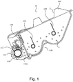
- FIG. 1 is a sectional view of the cartridge B.
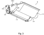
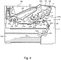
- Figures 2 and 3 are perspective views of the cartridge B.
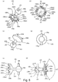
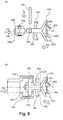
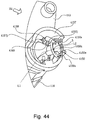
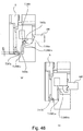
- Figure 4 is a sectional view of the main assembly A of an electrophotographic image forming apparatus (which hereafter will be referred to simply as main assembly A) .
- the cartridge B is attachable to, or detachable from, the main assembly A by a user.
- the cartridge B has a development roller 110.
- the cartridge B is mounted in the main assembly A. It rotates by receiving rotational force from the main assembly A through a coupling mechanism (which will be described later) while the cartridge B is properly situated in its image forming position in the main assembly A.
- the development roller 110 supplies the portion of an electrophotographic photosensitive drum 107 (which hereafter will be referred to simply as photosensitive drum) ( Figure 4 ), which is in the development area of the apparatus main assembly A, with developer t. It develops an electrostatic latent image on the peripheral surface of the photosensitive drum 107, with the use of the developer t.
- a magnetic roller 111 stationary magnet
- the cartridge B is provided with a development blade 112, which is in contact with the development roller 110.
- the development blade 112 regulates the amount by which the developer t is allowed to remain on the peripheral surface of the development roller 110. It also frictionally charges the developer t.
- the developer t is stored in the developer storage portion 114 of the cartridge B, and is sent into the development chamber 113a of the cartridge B, by the rotation of the toner stirring members 115 and 116 of the cartridge B.
- the development roller 110 is rotated while voltage is applied to the development roller 110.
- a layer of the frictionally charged developer t is formed on the peripheral surface of the development roller 110 by the development roller 110.
- the charged toner particles in this layer of the frictionally charged developer are transferred onto the photosensitive drum 107 in the pattern of the abovementioned electrostatic latent image; the development roller 110 develops the latent image.
- the developed image on the photosensitive drum 107 that is, the image formed of the developer t, is transferred onto a sheet of recording medium 102 by a transfer roller 104.
- the recording medium may be any medium on which an image can be formed (onto which image formed of developer (toner) can be transferred).
- it may be an ordinary piece of paper, OHP sheet, and the like.
- the cartridge B has a development unit 119, which is made up of a developing means holding frame 113 and a developer storing frame 114. More specifically, the development unit 119 has the development roller 110, development blade 112, developing means frame portion, development chamber 113a, developer storing frame portion 114, and stirring members 115 and 116.
- the development roller 110 is rotatable about its axial line L1.
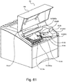
- the apparatus main assembly A is provided with a cartridge compartment 130a, into which a user is to mount the cartridge B by holding the cartridge B by the handhold T of the cartridge B.
- the coupling 150 rotational force transmitting member, which will be described later
- the cartridge B becomes connected to the drive shaft 180 ( Figure 17 ), with which the apparatus main assembly A is provided, making it possible for the development roller 110, etc., to rotate by receiving rotational force from the apparatus main assembly A.
- the user is to pull the cartridge B by grasping the handhold T.
- the coupling 150 of the cartridge B becomes disengaged from the driving shaft 180.
- the direction in which the cartridge B is to be moved to attach the cartridge B to the apparatus main assembly A (to mount cartridge into cartridge compartment 130a), or detach the cartridge B from the apparatus main assembly A (to dismount cartridge from cartridge compartment 130a), is practically perpendicular to the axial line L3 of the drive shaft 180. This subject will be described later in detail.
- the image forming apparatus 100 in this embodiment is a laser beam printer.
- Designated by a referential letter A is the main assembly of the image forming apparatus 100.
- the apparatus main assembly A is what remains after the removal of the cartridge B from the image forming apparatus 100.
- the apparatus main assembly A is provided with a charge roller 108 (charging member), which is parallel to the photosensitive drum 107.
- the charge roller 108 charges the photosensitive drum 107 with the voltage applied to the charge roller 108 from apparatus main assembly A. It is in contact with the photosensitive drum 107, and is rotated by the rotation of the photosensitive drum 107.
- a drum unit 120 has the photosensitive drum 107 and a cleaning blade 117a (cleaning means).
- the drum unit 120 has also a storage bin 117b for removed developer, a screw 117c for conveying the removed developer to a box (unshown) with which the apparatus main assembly A is provided to store the removed developer, and the charge roller 108.
- These components are integrally disposed in the apparatus main assembly A. That is, the unit 120 (cartridge B) and the apparatus main assembly A are structured so that as the cartridge B is mounted into the apparatus main assembly A, the photosensitive drum 107 is precisely positioned in its preset position (cartridge position) in the apparatus main assembly A.
- the unit 120 is provided with a pair of bearings (unshown), which protrude outward from the lengthwise ends of the cartridge B, one for one, and the axial line of each of which coincides with the axial line of the photosensitive drum 107.
- the cartridge B is supported by the pair of bearings, which are in a pair of grooves (unshown), one for one, with which the apparatus main assembly A is provided.
- the removed developer mentioned above is the developer which was removed from the photosensitive drum 107 by the blade 117a.
- the unit 120 may be made solidly attachable to, or removably mountable in, the apparatus main assembly A.
- the structural arrangement for positioning the unit 120 in the apparatus main assembly A so that the photosensitive drum 107 in the unit 120 is precisely positioned for image formation, relative to the main assembly A any one of the known structural arrangements may be employed.
- the cartridge B is mounted in the apparatus main assembly A (cartridge compartment 130a). Then, a user is to close the cartridge compartment door 109 with which the apparatus main assembly A is provided. As the cartridge door 109 is closed, the cartridge B is pressed toward the photosensitive drum 107 by the resiliency of a pair of spring 192 which are on the inward side of the door 109 is provided. Therefore, the development roller 110 is kept pressed toward surface of the photosensitive drum 107, in such a manner that a proper amount of distance is maintained between the development roller 110 and photosensitive drum 107 ( Figure 4 ). That is, the cartridge B is precisely positioned relative to the photosensitive drum 107. Thus, the development roller 110 is precisely positioned relative to the photosensitive drum 107.
- the lengthwise ends of the drum shaft (unshown) of the photosensitive drum 107 are fitted with the pair of bearings 107a, one for one, which are coaxial with the drum shaft. Further, the pair of bearings 107a are supported by a pair of bearing positioning portions 150, with which the apparatus main assembly A is provided. Thus, the photosensitive drum 107 is rotatable while remaining precisely positioned relative to the apparatus main assembly A ( Figures 4 and 5 ).
- the door 109 is to be opened by a user when the cartridge B needs to be attached to the apparatus main assembly A by the user, or when the cartridge B needs to be taken out the apparatus main assembly A by the user.
- the image forming operation to be carried out by this electrophotographic image forming apparatus is as follows:
- the rotating photosensitive drum 107 is uniformly charged by the charge roller 108, across the portion of its peripheral surface, which is moving in contact with the charge roller 108.
- a beam of laser light is projected, while being modulated with the information regarding the image to be formed, upon the charged portion of the peripheral surface of the photosensitive drum 107, by an optical means 101 having laser diodes, polygon mirror, lenses, and deflective mirrors (which are not shown).
- an electrostatic latent image which reflects the information regarding the image to be made, on the peripheral surface of the photosensitive drum 107.
- This latent image is developed by the abovementioned development roller 110.
- a sheet of recording medium 102 in a cassette 103a is sent out of the cassette 103, and then, is conveyed to the image transferring position by pairs 103c, 103d, and 103e, of recording medium conveyance rollers.
- voltage is applied from the apparatus main assembly A.
- the image formed on the photosensitive drum 107, of the developer transfers onto the sheet of recording medium 102.
- the apparatus main assembly A is provided with a cleaning blade 117a, which extends from one lengthwise end of the photosensitive drum 107 to the other, and the cleaning edge of which is elastically in contact with the peripheral surface of the photosensitive drum 107.
- the cleaning blade 117a is for removing the developer t remaining on the peripheral surface of the photosensitive drum 107 after the transfer of the developer image onto the recording medium 102.
- the developer t is temporarily stored in the developer bin 117b.
- the removed developer t in the developer bin 117b is conveyed to abovementioned box (unshown) for removed developer, by a developer conveying screw 117c in the developer bin 117b, and then, is accumulated in the box.
- the recording medium 102 is conveyed to a fixing means 105 by a guide 103f.
- the fixing means 105 is provided with a driving roller 105c, and a fixing roller 105 which contains a heater 105a.
- the fixing means 105 fixes the developer image to the recording medium 102 by applying heat and pressure to the recording medium while the recording medium 102 is conveyed through the fixing means 105.
- the recording medium 102 is conveyed further, and then, is discharged into a tray 106, by a pair of rollers 103g and a pair of rollers 103h.
- the pairs of rollers 103c, 103d, and 103e, guide 103f, and pairs of rollers 103g and 103h, etc., make up the recording medium conveying means 103.
- the cartridge compartment 130a is the room (space) in which the cartridge B is to be set. As the cartridge B is mounted into this room, the coupling 150 of the cartridge B (which will be described later) becomes connected to the drive shaft 180 with which the apparatus main assembly A is provided.
- the placement of the cartridge B in the cartridge compartment 130a is synonymous to the attachment of the cartridge B to the apparatus main assembly A.
- the removal of the cartridge B from the cartridge compartment 130a is synonymous to the detachment of the cartridge B from the apparatus main assembly A.
- Figure 5(a) is a perspective view of the development roller 110 as seen from its rotational force receiving side (which hereafter may be referred to as driving force receiving side).
- Figure 5(b) is a perspective view of the development roller 110 as seen from the opposite side from the driving force receiving side (which hereafter may be referred to simply as opposite side).
- the development roller 110 is made up of a development roller cylinder 110a, a development roller flange 151 (which is at driving force receiving end), a development roller flange 152 (which is at opposite end), and a magnetic roller 111.
- the development roller cylinder 110a is made up of a cylinder made of an electrically conductive cylinder, such as an aluminum cylinder, and a coated layer.
- the cylinder 110a bears the developer on its peripheral surface.
- the developer borne on the cylinder 110a is charged.
- the lengthwise ends of the cylinder 110a are provided with openings 110a1 and 110a2, one for one, which are roughly the same in diameter as the cylinder 110a, and are fitted with the abovementioned flanges 151 and 152, respectively.
- the flange 151 is formed of a metallic substance, such as aluminum, stainless steel, etc. However, it may be formed of a resinous substance, as long as it can withstand the amount of torque necessary to rotate the development roller 110.
- the flange 151 is provided with a gear fitting portion 151c, around which the development roller gear 153 ( Figure 8(b) ) for driving the developer stirring members 115 and 116 ( Figure 1 ), etc., is fitted. It is also provided with a bearing fitting portion 151d, around which the development roller bearing 138 is fitted to rotatably support the development roller 110.
- the gear fitting portion 151c and bearing fitting portion 151d are coaxial with the flange 151.
- the flange 151 is also provided with an internal cavity for supporting the magnetic roller 111, which will be described later.
- the development roller gear 153, with which the flange 151 is fitted, is fitted with the coupling 150 (which will be described later) in such a manner that the coupling 150 can be tilted relative to the axial line of the development roller 110 even while being moved.
- the flange 152 is made of a metallic substance, such as aluminum or stainless steel, as is the flange 151.
- the flange 152 also may be made of a resinous substance as long as it can withstand the amount of load to which the development roller 110 is subjected.
- the axial line of the cylinder fitting portion 152b roughly coincides with that of the bearing 152a.
- one of the lengthwise end portions of the magnetic roller 111 is made to extend beyond the corresponding lengthwise end of the development roller 110, and is supported by the bearing 152a.
- the magnetic roller 111 is formed of a magnetic substance, or a resinous substance into which magnetic particles have been mixed.
- the magnetic roller 111 is provided with two to six magnetic poles, which are distributed in its circumferential direction. It contributes to the conveyance of the developer, by holding the developer on the peripheral surface of the development roller 110.
- the above-described magnetic roller 111 is placed in the development roller cylinder 110a, and the fitting portion 151a of the flange 151 is fitted in the opening 110a1 of the development roller cylinder 110a. Further, the fitting portion 152b of the flange 152 is fitted in the opening 110a2 of the other lengthwise end of the development roller cylinder 110a.
- the method for solidly attaching the flanges 151 and 152 to the development roller cylinder 110a is adhesion, crimping, etc.
- a spacer 136, the development roller bearing 138, and the development roller gear (unshown) are fitted from the driving force receiving side of the development roller 110. Further, a spacer 137 and development roller contact 156 is fitted from the opposite side of the development roller 110.
- the spacers 136 and 137 are the members for regulating the gap between the development roller 110 and photosensitive drum 107.
- the spacer 136 is fitted around one of the lengthwise end portions of the development roller cylinder 110a, and the spacer 137 is fitted around the other lengthwise end portion of the development roller cylinder 110a. With the fitting of the development roller 110 with the spacers 136 and 137, a gap of roughly 200 - 400 ⁇ m is maintained between the development roller 110 and photosensitive drum 107.
- the bearing 138 is the bearing for rotatably supporting the development roller 110 by the development unit frame 113 ( Figure 1 ).
- the development voltage contact 156 is formed of an electrically conductive substance (primarily, metallic substance), and is in the form of a coil.
- the internal surface of the electrically conductive development roller cylinder 110a, or the flange 152, is provided with the development voltage contact 156b.
- the image forming apparatus is structured so that the development voltage contact 156 contacts the flange 152.
- the electrical contacts (unshown), with which the apparatus main assembly A is provided, remain in contact with the external electrical contacts of the cartridge B, making it possible for the cartridge B to receive electrical voltage from the apparatus main assembly A.
- the voltage received by the external electrical contact of the cartridge B is supplied to the development roller 110 through the electrical contact 156.
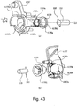
- Figure 6 is a perspective view of a coupling member, as seen from the main assembly side
- figure 6 (b) is a perspective view of the coupling member, as seen from the developing roller side
- Figure 6 (c) is a view, as seen in a direction perpendicular to a direction of the coupling axis L2.
- Figure 6 (d) is a side view of the coupling member, as seen from the main assembly side
- figure 6 (e) is a view, as seen from a developing roller side.
- Figure 6 (f) is a sectional view taken along the line S3 in Figure 6 (d) .
- the coupling member (coupling) 150 engages with the drive shaft 180 ( Figure 17 ) of the main assembly A.
- the coupling 150 is disengaged from the drive shaft 180 by taking the cartridge B out of the main assembly A.
- the cartridge B is moved in a direction substantially perpendicular to a direction of the axis L3 of the drive shaft 180 from the set portion in the main assembly A.
- the cartridge B is moved to the set portion of the main assembly A in the direction substantially perpendicular to the direction of the axis L3 of the drive shaft 180.
- the coupling 150 receives a rotational force from the motor 186 ( Figure 14 ) provided in the main assembly A through the drive shaft 180.
- the coupling 150 transmits the rotational force to the developing roller 110.
- the material of the coupling 150 is the resin material of polyacetal, polycarbonate PPS, or the like.
- the glass fiber, the carbon fiber, or the like may be mixed in the resin material in accordance with the required load torque. When such material is mixed, a rigidity of the coupling 150 can be raised.
- the rigidity may further be raised by inserting a metal member.
- the whole coupling 150 may be manufactured from metal or the like.
- the material of the coupling is similar also in the embodiments as will be described hereinafter.
- the coupling 150 has three main parts ( Figure 6 (c) ).
- the first portion is a driven portion 150a which has a rotational force reception surface (rotational force receiving portion) 150e (150e1 to 150e4) for receiving the rotational force from the pin 182 by engaging with the drive shaft 180.
- the second portion is a driving portion 150b for transmitting the rotational force by engaging with the development gear 153.
- the third portion is an intermediate part 150c between the driven portion 150a and the driving portion 150b.
- the development gear 153 transmits the rotational force received by the coupling 150 from the main assembly A to a developer supply roller, for example (as will be described hereinafter).
- the driven portion 150a has a drive shaft insertion opening 150m which is an expanded part which expands in the shape of conic away from the axis L2.
- the opening 150m constitutes a recess 150z.
- the recess 150z is co-axial with the rotation axis L2 of the coupling 150.
- the driving portion 150b has a spherical driving shaft receiving surface 150i.
- the coupling 150 can substantially pivot (move) between a rotational force transmitting angular position and a pre-engagement angular position (or a disengaging angular position) relative to the axis L1.
- the coupling 150 engages with the drive shaft 180 without being obstructed by a free end portion 180b of the drive shaft 180, irrespective of a rotational phase of the developing roller 110.
- the driving portion 150b has a projecting configuration.
- a plurality of drive receiving projections 150d1-d4 are provided on the circumference ( Figure 6(d) , phantom circle C1) of an end surface of the driven portion 150a.
- the drive receiving stand-by portions 150k1, 150k2, 150k3, 150k4 is provided between the adjacent projections 150d 1 or 150d 2 or 150d3, 150d4.
- the intervals of the adjacent projections 150d1-d4 are larger than an outer diameter of the pins 182 so that the pins (the rotational force applying portions) 182 can enter the intervals.
- These clearance portions of the intervals are standing-by portions 150k1-k4.
- the clockwise downstream side of the projection 150d is provided with a rotational force reception surface (the rotational force receiving portion) 150e crossing with the rotational direction of coupling 150, and (150e1-e4).
- the pins 182 abut to one of the receiving surfaces 150e1-e4.
- the receiving surfaces 150e1-e4 are pushed by the peripheries of the pins 182, so that the coupling 150 rotates about the axis L2.
- the driving portion 150b has a spherical surface. For this reason, in the cartridge B, irrespective of the rotational phase of the developing roller 110, the coupling 150 can substantially pivot (move) between the rotational force transmitting angular position and the pre-engagement angular position (or the disengaging angular position).
- the driving portion 150b is constituted by the spherical developing shaft receiving surface 150i which has the axis L2 as the axis thereof. And, at the position passing through the center thereof, a fixing hole 150g penetrated by the pin (the rotational force transmitting portion) 155 is provided.
- the coupling 150 has the recess 150z co-axial with the rotation axis L2 of the coupling 150.
- the recess 150z covers the free end of the drive shaft 180.
- the rotational force reception surface 150e (150e1 to 150e4) engages with the rotational force transmitting pins (rotational force applying portion) 182 which project in the direction perpendicular to the axis L3 of the drive shaft 180 in the free end portion of the drive shaft 180 in the rotational direction of the coupling 150.
- the rotational force reception surface 150e is the rotational force receiving portion.
- the pin 182 is the rotational force applying portion.
- the coupling 150 receives the rotational force from the drive shaft 180 to rotate.
- the cartridge B In dismounting the cartridge B from the main assembly A the cartridge B is moved, so that the coupling 150 moves in the direction substantially perpendicular to the axis L1 of the developing roller 110, in the cartridge
- the coupling 150 pivots (moves) to the disengaging angular position from the rotational force transmitting angular position, so that a part of recess 150z (free end position 150A1) circumvents the drive shaft 180.
- the coupling 150 can disengage from the drive shaft 180.
- the rotational force receiving surfaces (rotational force receiving portions) 150e are positioned, interposing the center S, on the phantom circle which has a center S on the rotation axis L2 of the coupling 150 C1 ( Figure 6 (d) ).
- the rotational force receiving surfaces 150e are disposed at four places.
- the force is uniformly applied to the coupling 150 by the opposing arrangement of the rotational force reception surfaces 150e. Accordingly, the rotational accuracy of the coupling 150 can be improved.
- the axis L2 of the coupling 150 In the state of being in the rotational force transmitting angular position the axis L2 of the coupling 150 is substantially co-axial with the axis L1 of the developing roller 110. In the state that the coupling 150 is in the disengaging angular position, it inclines relative to the axis L1 so that in the removing direction X6 of dismounting the cartridge B, the upstream side (free end portion 150 A3) can pass by the free end of the drive shaft 180 from the main assembly A.
- Figure 7 is a view, as seen from the drive shaft side, and Figure 7 (b) is a sectional view taken along a line S4-S4 in Figure 7(a) .
- the openings 153g 1 or 153g2 shown in Figure 7(a) are the grooves extended in a rotational axis direction of the development gear 153.
- a space portion 153f is provided between the openings 153g 1, 153g2.
- the pins 155 are received in the opening 153g 1, 153g2.
- the developing shaft receiving surface 150i is accepted in the space portion 153f.
- the coupling 150 is pivotable (movable) between the rotational force transmitting angular position and the pre-engagement angular position (or the disengaging angular position).
- the clockwisely upstream side of the openings 153g 1, 153g2 is provided with the rotational force transmitting surfaces (rotational force transmitted portions) 153h 1, 153h2.
- the sides of the rotational force transmitting pin (rotational force transmitting portion) 155 of coupling 150 contact to the transmitting surfaces 153h 1 or 153h2.
- the rotational force is transmitted to the developing roller 110 from the coupling 150.
- the transmitting surface 153h 1-153h2 is the surface which faces in the rotational direction of the development gear 153. Therefore, the transmitting surfaces 153h 1-153h2 are pushed by the sides of the pin 15155. In the state in which the axis L1 and the axis L2 are substantially co-axial with each other the coupling 150 rotates about the axis L2.
- the development gear 153 has transmitted portions 153h 1 or 153h2 here, and therefore, they function as a rotational force transmitted member.
- Figure 8 is a sectional view illustrating the process in which the coupling 150 is assembled into the development gear 153.
- Figure 8 (a) is a view illustrating the state of assembling the drive transmission pin and the retaining member 156 to the coupling 150 which comprises two parts.
- Figure 8 (b) is a view illustrating the process in which the structure thus assembled is assembled to the development gear.
- the retaining member 156 is locked with the development gear 153.
- the coupling 150 is mounted so that they are pivotable (movable) between the rotational force transmitting angular position and the pre-engagement angular position (or the disengaging angular position). And, the movement, in the direction of the axis L2, of the coupling 150 is restricted. For this reason, the opening 156j has a diameter D15 smaller than the diameter of the shaft receiving surface 150i. More particularly, the movement of the coupling 150 is regulated by the development gear 153 and a retaining member 156. By this, the coupling 150 does not separate from the developing roller (the cartridge).
- the driving portion 150b of the coupling 150 is in engagement with the recess (space portion 153f) of the development gear 153.
- the driven portion 150a and the intermediate part 150c are inserted in the direction X33 relative to the positioning member 150q which has the shaft receiving surface 150i (driving portion 150c).
- the retaining member 156 is placed between the driven portion 150c and the positioning member 150q beforehand.
- the pin 155 penetrates the fixing hole 150g of the positioning member 150q and the fixing hole 150r of the intermediate portion 150c. By this, the positioning member 150q is fixed to the intermediate portion 150c.
- the coupling 150 is moved in the direction X33.
- the coupling 150 is inserted into the development gear 153.
- the retaining member 156 is inserted in the direction of an arrow X33.
- the retaining member 156 is fixed to the development gear 153.
- the coupling 150 can be mounted with play (gap) between the positioning member 150q and the development gear 153.
- the coupling 150 can change the orientation thereof (inclination and/or movement relative to the axis L2).
- the mounting method of the coupling is not limited to these mounting methods.
- the coupling not movable in the axial direction relative to the development gear 153, and that inclinable relative to the axis of the development gear 153 (developing roller 110).
- the coupling is formed integrally.
- a flexible locking claw is provided on the development gear 153, and the shaft receiving surface 150i is locked by this. In this manner the retention may be accomplished.
- the retaining member may also be used.
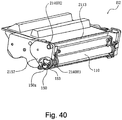
- Figure 9 is an exploded perspective view illustrating the driving side of the cartridge.
- Figure 10 (a) is the sectional view taken along the line S4-S4 in Figure 2 wherein the axis L2 is co-axial with the axis L1.
- Figure 10 (b) is a sectional view taken along the line S5-S5 in Figure 2 .
- the development gear 153 which has the coupling 150 is fixed to the one-end portion (developing roller flange 151) of the developing roller 110 so that the driving portion 150a is exposed.
- the driving side of the integral structure (developing roller 110, development gear 153, coupling 150) is supported by the bearing member 157, and the non-driving side is supported by the development supporting pin (unshown). And, in this state, the integral structure is rotatably supported on the developing device frame 119. By this, they are unified into the cartridge B ( Figure 2 and Figure 3 ).
- the axis L2 of the coupling 150 can be in the state of being substantially co-axial with the axis L1 of the developing roller 110 ( Figure 10 (a) ), and also can be in the state of inclining relative to the axis L1 ( Figure 10 (b) ).
- Figure 11 here, the coupling 150 is mounted to the developing device frame 119 so that the axis L2 can incline in any directions relative to the axis L1.
- Figure 11 (a1) - (a5) is views as seen in the direction of the drive shaft 180, and is perspective views of the elements shown in Figure 11 (b1) - (b5).
- figure 11 (b1) - (b5) illustrates a substantial entirety of the coupling 150 with the development gear 153 exploded partially.
- the axis L2 can incline in the all directions relative to the axis L1.
- the opening 151g extends in the direction crossing with the projecting direction of the pin 155.
- the coupling 150 is inclinable (movable) in all the directions.
- the transmitting surface (rotational force transmitted portion) 153h, (153h1, h2) is movable relative to the pin 155 (rotational force transmitting portion).
- the pin 155 is movable relative to the transmitting surface 153h.
- the transmitting surface 153h and the pin 155 are engaged to each other.
- the gap is provided between the pin 155 and the transmitting surface 153h.
- the coupling 150 is pivotable over substantially all directions relative to the axis L1. In this manner, the coupling 150 is mounted to the end of the developing roller 110.
- the axis L2 is inclinable in all the directions relative to the axis L1.
- the coupling 150 does not necessarily 360 degrees need to be inclinable linearly to the predetermined angle in any direction.
- the opening 150g for example is more widely set in the circumferential direction. If it is set in this manner, it can be rotated to a slight degree by the coupling 150 relative to the axis L2, even in the case where the axis L2 cannot linearly incline by the predetermined angle, when the axis L2 inclines relative to the axis L1. By this, it can incline to the predetermined angle. In other words, the amount of the play of the rotational direction of the opening 150g can be selected properly if necessary.
- the coupling 150 is pivotably mounted in any direction substantially.
- the coupling 150 is revolvable (movable) over the full-circumference substantially relative to the development gear 153 (axis L1 of the developing roller 110).
- the spherical surface 150i of the coupling 150 contacts to the retaining portion (a part of recess) 156i.
- the coupling 150 is mounted concentrically with the center P2 of the spherical surface 150i ( Figure 10 ). More particularly, irrespective of the phase of the development gear 153 (developing roller 110), the axis L2 of the coupling 150 is inclinable.
- the axis L2 inclines toward the downstream side with respect to the mounting direction of the cartridge B relative to the axis L1, immediately before the engagement.
- the axis L2 is inclined so that the driven portion 150a is the downstream of the axis L1 with respect to the mounting direction X4.
- the position of the driven portion 150a is downstream relative to the mounting direction X4 in any case.
- the maximum possible inclination angle ⁇ 4 ( Figure 10 (b) ) between the axis L1 and the axis L2 is the inclination angle at which the driven portion 15150a or the intermediate portion 15150c contacts to the development gear 153 or the bearing member 157.
- This inclination angle is the angle which permits the engagement and disengagement of the coupling 150 relative to the drive shaft 180 at the time of mounting and demounting the cartridge B to the main assembly A.
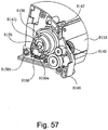
- Figure 13 is a perspective view of the main assembly in the state that the cartridge B is not inserted, wherein the side plate of the driving side is omitted partially.
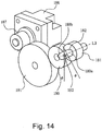
- Figure 14 is a perspective view illustrating only the developing roller driving structure.
- the free end portion 180b of the drive shaft 180 is a semispherical surface. It has a rotational force transmitting pin 182 as a rotational force applying portion which penetrates substantially the center of the cylindrical main part 180a. The rotational force is transmitted to the coupling 150 by this pin 182.
- the longitudinally opposite side from the free end portion 180b is provided with a development drive gear 181 substantially co-axial with the axis L3.
- the gear 181 is fixed non-rotatably on the drive shaft 180. For this reason, when the gear 181 rotates, the drive shaft 180 also rotates.
- the gear 181 receives the rotational force through a pinion gear (motor pinion) 187, an idler gear 191, and a photosensitive drum driving gear 190 from the motor 186. For this reason, when the motor 186 rotates, the drive shaft 180 also rotates.
- the gear 181 is supported rotatably by the main assembly A by through bearing member (unshown). At this time, the gear 181 is not moved in the direction of the axis L1. For this reason, the gear 181 and the bearing member (unshown) can be disposed closely relative to each other.
- the gear 181 receives the transmission of the rotational force through the gears from the gear 187. This is not inevitable. For example, proper modification is possible from the viewpoint of the convenience of the disposition of the motor 186.
- the rotational force may be transmitted by belt or the like.
- the drive shaft 180 is not moved in the direction thereof of the axis L3.
- the gap between the drive shafts 180 and the bearing members 183, 184 is a gap for permitting the rotation of the drive shaft 180. Therefore, the position of the gear 181 relative to the gear 187 can also accurately be determined with respect to the diametrical direction.
- the drive shaft 180 may have play (gap) in the direction of the axis L3.
- the drive shaft 180 or the gear 181 may elastically be urged by a spring or the like in the direction of the axis L3.
- the cartridge mounting means 130 in this embodiment has a pair of cartridge guides 130R1 and 130L1, with which the main assembly A is provided.
- These guides 130R1 and 130L are in the space (cartridge compartment 130a) in which the cartridge B is to be mounted. That is, the cartridge compartment 130a is provided with the cartridge mounting means 130, the cartridge guides 130R1 and 130L1 of which are located next to its end walls (left and right walls), one for one, and extend in the direction in which the cartridge B is inserted (mounted) into the cartridge compartment 130a.
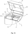
- the two guides 130R1 and 130L1 of the cartridge mounting means 130 are disposed next to the left and right walls of the cartridge compartment 130a, in such a manner that they squarely oppose each other across the cartridge compartment 130a ( Figure 15 shows side from which cartridge is driven, and Figure 16 shows opposite side from which cartridge is driven).
- the cartridge mounting means 130 is provided with the pair of cartridge guiding portions 130R1 and 130L1, which guide the cartridge B when the cartridge is mounted into the cartridge compartment 130a.
- the guiding portion 130R1 is located at one end (right end, as seen from direction from which cartridge B is inserted) of the cartridge compartment 130a, and the guiding portion 130L1 is located at the other end. They are positioned so that they oppose each other across the cartridge compartment 130a.
- the procedure for mounting the cartridge B in the apparatus main assembly A is as follows: First, a user is to open the door 109, which can be opened or closed about the shaft 109a. Then, the user is to insert the cartridge B into the cartridge compartment 130a while allowing the abovementioned bosses to be guided by the guiding portions 130R1 and 130L1. Then, the user is to close the door 109. The closing of the door 109 ends the mounting of the cartridge B into the apparatus main assembly A. Incidentally, the user is to open the door 9 also when the user takes the cartridge B out of the apparatus main assembly A.
- a groove 130R2 which is on the cartridge driving side of the cartridge compartment 130a, functions as a clearance for the coupling 150, until the coupling 150 engages with the drive shaft 180.
- the door 109 is provided with a spring 192, which is on the inward side of the door 109.
- the spring 192 keeps the cartridge B elastically pressed so that a preset amount of distance is maintained between the development roller 110 and photosensitive drum 107. That is, the spring 102 keeps the cartridge B elastically pressed so that the development roller 110 is kept pressed toward the photosensitive drum 107.
- the cartridge B is provided with a pair of cartridge guides 140R1 and 140R2, and a pair of cartridge guides 140L1 and 140L2.
- the cartridge guides 140R1 and 140R2 are at one of the lengthwise ends of the cartridge B, and the cartridge guides 140L1 and 140L2 are at the other lengthwise end.
- the guides 140R1, 140R2, 140L1 and 140L2 are integral parts of the development unit frame 119, development roller supporting members 157, or development roller bearings 139, and are integrally molded therewith. They protrude outward of the cartridge B.
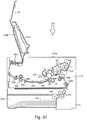
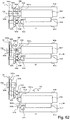
- Figures 17(a) - 17(c) are cross sectional views of the cartridge B and cartridge compartment portion of the apparatus main assembly A, at a plane S6-S6 in Figure 15 .
- a user is to open the door 109 of the apparatus main assembly A, and to mount the cartridge B into the cartridge mounting means 130 (cartridge compartment 130a).
- the cartridge B is to be mounted into the cartridge compartment 130a by inserting the cartridge B into the apparatus main assembly A in such a manner that the cartridge guides 140R1 and 140R2, which are on the driving force receiving side, follow the cartridge guide 130R1 of the apparatus main assembly A, and also, so that the cartridge guides 140L1 and 140L2 ( Figure 3 ), which are on the opposite side from the driving force receiving side, follow the cartridge guide 130L1 ( Figure 16 ) of the apparatus main assembly A.
- the coupling 150 which is on the driving force receiving side
- the cylindrical portion 157c of the development roller supporting member 157 which surrounds the coupling 150, follow the groove 130R2 of the guide 130R1, with no contact between the cylindrical portion 157c and the walls of the groove 130R2.
- the cartridge B is to be inserted further in the direction indicated by an arrow mark X.
- the coupling 150 engages with the drive shaft 180, allowing the cartridge B to properly settle in the cartridge compartment 130a (preset position in cartridge compartment 130a), as will be described later in more detail.
- the guide 140R1 comes into contact with the cartridge positioning portion 130R1a of the guide 130R1.
- the guide 140L1 comes into contact with the cartridge positioning portion 130L1a ( Figure 16 ) of the guide 130L1.
- the cartridge B is removably mounted into the cartridge compartment 130a while being assisted by the cartridge mounting means 130.
- the coupling 150 engages with the driving shaft 180 toward the end of the mounting (insertion) of the cartridge B into the cartridge compartment 130a. While the cartridge B remains properly positioned in the image forming position in the cartridge compartment 130a, the coupling 150 remains engaged with the drive shaft 180 so that the cartridge B can perform a part of an image forming operation.
- the cartridge compartment 130a is the space in the apparatus main assembly A, which the cartridge B occupies while the cartridge B remains in the apparatus main assembly A after being mounted into the apparatus main assembly A by the user while being assisted by the cartridge mounting means 130.
- the cartridge B is provided with the pair of guides 140R1 and 140R2, which protrude from one of the lengthwise ends of the cartridge B ( Figure 2 ).
- a preset amount of distance (gap) between the guides 140R1 and 140R2.
- the cartridge B is also provided with the pair of guides 140L1 and 140L2, which protrude from the other lengthwise end of the cartridge B ( Figure 3 ).
- a preset amount of distance (gap) is provided between the guides 140L1 and 140L2.
- one end of its cartridge compartment 130a in terms of the direction perpendicular to the cartridge mounting direction X4, is provided with the guide 130R1 and 130R2, which align with each other in the direction parallel to the cartridge mounting direction X4, with the guide 130R1 positioned higher than the guide 130R2 ( Figure 15 ).
- the other end of the cartridge compartment 130a is provided with the guides 130L1 and 130L2, which align with each other in the direction parallel to the cartridge mounting direction X4 ( Figure 16 ).
- the cartridge B when the cartridge B is mounted into the cartridge compartment 130a, it is to be inserted into the cartridge compartment 130a in such a manner that the guides 140R1 and guide 140R2 are guided by the guide 130R1, and the bottom surface of the cartridge B is guided by the guide 130R2 ( Figure 17 ).
- the guide 140L1 and guide 140L2 are guided by the guide 130L1.
- the guides 140R1 ( Figure 17 ) and 140L1 ( Figure 16 ) are precisely positioned relative to the cartridge compartment 130a by the cartridge positioning portions 130R1a and 130L1a, respectively, after the engagement of the coupling 150 with the drive shaft 180. That is, the cartridge B is precisely positioned in the cartridge compartment 130a after the engagement of the coupling 150 with the drive shaft 180.
- the cartridge B can be taken out of the cartridge compartment 130a simply by carrying out in reverse the above described cartridge mounting operation.
- the above described structural arrangement for the cartridge B and apparatus main assembly A makes it possible to remove the cartridge B from the cartridge compartment 130a by moving the cartridge B in the direction which is practically perpendicular to the axial line of the drive shaft 180. That is, the cartridge B can be mounted into, or removed from, the cartridge compartment 130a, by moving the cartridge B in the direction which is practically perpendicular to the axial line of the drive shaft 180.
- the guide 140R1 remains under the pressure from the resiliency of the spring 188R, with which the apparatus main assembly A is provided ( Figure 2 as well as Figure 15 ), whereas the guide 140L1 remains under the pressure from the resiliency of the spring 188L, with which the apparatus main assembly A is provided ( Figure 3 as well as Figure 16 ).
- the cartridge B is kept pressed upon the cartridge seat 114a ( Figure 4 ) by the resiliency of the spring 192R (as for spring 192L, that is, spring on opposite side from driving force receiving side, see Figure 16 ) attached to the inward surface of the color 109.
- the spacers 136 and 137 ( Figure 2 ) fitted around the lengthwise end portions of the development roller 110, one for one, are kept in contact with the lengthwise end portions of the photosensitive drum 107, whereby the preset amount of distance is maintained between the development roller 110 and photosensitive drum 107.
- the closing of the cover 109 causes a switching means (unshown) to be turned on, making it possible for the development roller 110 to receive the rotational force for rotating the development roller 110, from the apparatus main assembly A through the drive shaft 180 and coupling 150.
- the cartridge B is removably mounted in the cartridge compartment 130a by a user while being guided by the cartridge mounting means 130. That is, the cartridge B is mounted into the cartridge compartment 130a while remaining precisely positioned relative to the apparatus main assembly A and photosensitive drum 107. Further, the drive shaft 180 and coupling 150 becomes fully engaged after the precise positioning of the cartridge B in the cartridge compartment 130a.
- the coupling 150 is made to take its rotational force receiving attitude.
- the electrophotographic image forming apparatus in this embodiment is enabled to form an image, by the mounting of the cartridge B into the cartridge compartment 130a of the image forming apparatus.
- the apparatus main assembly A and cartridge B may be structured so that the cartridge B is to be inserted all the way into the cartridge compartment 130a by a user himself or herself, or the cartridge B is to be inserted partway by the user to make it possible for the cartridge B to be mounted the rest of the way by another means.
- the apparatus main assembly A may be structured so that as the door 109 is closed, a part of the door 109 comes into contact with the cartridge B, which has been inserted partway, and then, the cartridge B is pushed into its final position in the cartridge compartment 130a by the rest of the closing movement of the door 109.
- the cartridge B and apparatus main assembly A may be structured so that the cartridge B is to be pushed partway into the cartridge compartment 130a by a user, and then, the cartridge B is advanced into its final the position in the cartridge compartment 130a by its own weight.
- the cartridge B is mounted and demounted relative to the main assembly A by moving in the direction substantially perpendicular to the direction of the axis L3 of the drive shaft 180 ( Figure 18 ). And, the drive shaft 180 and the coupling 150 are in the engaged state or the disengaged state.
- the small gap is given between them. More specifically, small gaps are provided between the longitudinal directions of the guide 140R1 and the guide 130R1, between the longitudinal directions of the guide 140R2 and the guide 130R1, between the longitudinal directions of the guide 140L1 and the guide 130L1, and between the longitudinal directions of the guide 140L2 and the guide 130L2. Therefore, in mounting and demounting the cartridge B relative to the main assembly A, the whole cartridge B may sometimes slightly be slanting within the limits of the gap thereof. Therefore, strictly speaking, the mounting and demounting is sometimes not in the orthogonality direction. However, even in such a case, the functional effect of the present invention is implementable. Therefore, the "substantial perpendicularity" includes the case where the cartridge slightly slanted.
- the coupling 150 of the cartridge B engages with the drive shaft 180 immediately before being positioned in the mounting portion 130a (predetermined position), or, simultaneously with the positioning to the predetermined position. More particularly, the coupling 150 is in the rotational force transmitting angular position.
- the predetermined position is the set portion 130a.
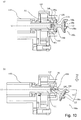
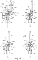
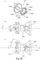
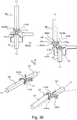
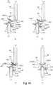
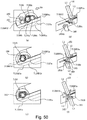
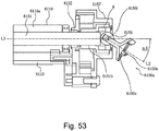
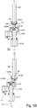
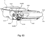
- Figure 18 is a perspective view illustrating the drive shaft and the major part of the driving side of the cartridge.
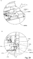
- Figure 19 is a longitudinal sectional view, as seen from below the main assembly.
- the engagement means the state in which the axis L2 and the axis L3 are substantially co-axial with each other, and in which the transmission of the rotational force is possible.
- the cartridge B is mounted to the main assembly A in the direction (direction of arrow X4) substantially perpendicular to the axis L3 of the drive shaft 180. Or, it is dismounted from the main assembly A.
- the coupling 150 is in the pre-engagement angular position, wherein the axis L2 ( Figure 19 (a) ) inclines toward the mounting direction X4 relative to the axis L1 ( Figure 19 (a) ) of the developing roller 110 beforehand ( Figure 18(a) and Figure 19 (a) ).
- the structures of the embodiment 4 as will be described hereinafter or the embodiment 5 are used for example.
- the present invention cannot be limited to these, but the other proper structure can be used.
- the downstream free end position 150A1 of the coupling 150 with respect to the mounting direction X4 is nearer, than the free end 180b3 of the drive shaft, to the position that the developing roller 110 is provided with respect to the direction of the axis L1.
- the upstream free end position 150A2 is nearer, than the free end 180b3 of the shaft, to the position that the pin 182 is provided with respect to the mounting direction X4 ( Figure 19 (a), (b) ).
- the free end position means the position which is remotest from the axis L2 at position closest to the drive shaft with respect to the direction of the axis L2 in the driven portion 150a shown in Figure 6 (a), (c) . In other words, it is one of an edge line of the driven portion 150a or an edge line of the projection 150d of the coupling 150 depending on the rotational phase of the coupling 150, ( Figure 6 (a), (c) , 150A).
- the free end position (a part of coupling 150) 150A1 of the coupling 150 passes by the free end 180b3 of the shaft. And, after the coupling 150 passes the free end 180b3 of the shaft, the receiving surface 150f or the projection 150d contacts to the free end portion 180b or the pin 182 of the drive shaft 180 ( Figure 19 (b) ).
- the receiving surface 150f and the projection 150d are the cartridge side contact portions.
- the drive shaft 180 is the main assembly side engaging portion.
- the pins 182 are the main assembly side engaging portion and the rotational force applying portion.
- the coupling 150 inclines ( Figure 19 (c) ) so that the axis L2 becomes coaxial with the axis L1.
- the coupling 150 inclines from the pre-engagement angular position, it pivots (moves) to the rotational force transmitting angular position at which the axis L2 thereof is substantially co-axial with the axis L1. Finally, the position of the cartridge B is determined relative to the main assembly A. At this time, the drive shaft 180 and the developing roller 110 are substantially co-axial with each other. Furthermore, in this state, the receiving surface 150f opposes to the spherical surface free end portion 180b of the drive shaft 180. And, the coupling 150 and the drive shaft 180 are engaged with each other ( Figure 18(b) and Figure 19(d) ). In addition, at this time, the pin 155 (unshown) is positioned in the opening 150g ( Figure 6 (b) ). In addition, the pin 182 is positioned in the standing-by portion 150k. Here, the coupling 150 covers the free end portion 180b.
- the coupling 150 makes the following motion. More particularly, while a downstream part of coupling 150 (free end position 150A1) with respect to the mounting direction X4 circumvents the drive shaft 180, the coupling 150 inclines moves toward the rotational force transmitting angular position from the pre-engagement angular position.
- the receiving surface 150f constitutes the recess 150z.
- the recess 150z has a conical shape.
- the mounting direction X4 is the direction for mounting the cartridge B to the main assembly A.
- the coupling 150 is mounted for inclining motion relative to the axis L1. And, in response to the movement of the cartridge B, the a part of coupling 150 (receiving surface 150f and/or projection 150d) which is the cartridge side contact portion contacts to the main assembly side engaging portion (drive shaft 180 and/or pin 182). By this, the pivoting motion of the coupling 150 is carried out. As shown in Figure 19 , the coupling 150 is mounted in the state that it overlaps, with respect to the direction of the axis L1, with the drive shaft 180. However, by the pivoting motion of the coupling s as described above, the coupling 150 can be engaged with the drive shaft 180 in the overlapping state.
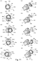
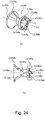
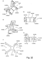
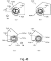
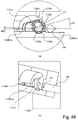
- Figure 20 is a view showing the respective phases of the coupling 150 and the drive shaft 180.
- Figure 20 (a) is a view showing the state that the pin 182 and the receiving surface 150f oppose to each other in the downstream side, with respect to the mounting direction X4, of the cartridge.
- Figure 20 (b) is a view showing the state that the pin 182 and the projection 150d oppose to each other.
- Figure 20 (c) is a view showing the state that the free end portion 180b and the projection 150d oppose to each other.
- Figure 20 (d) is a view showing the state that the free end portion 180b and the receiving surface 150f oppose to each other.
- the coupling 150 is inclinable in all directions relative to the axis L1 of the developing roller 110. More particularly, the coupling 150 is revolvable. As shown in Figure 20 , for this reason, in the mounting direction X4 of the cartridge B, it is inclinable irrespective of the phase of the development gear 153 (developing roller). Regardless of the phases of the drive shaft 180 and the coupling 150, the free end position 150A1 is inclinable in a set range of the inclination angle of the coupling 150 so that it is in the developing roller side beyond the free end 180b3 of the shaft in the direction of the axis L1.
- the range of the inclination angle of the coupling 150 is set so that the free end position 150A2 is positioned in the pin 182 side with respect to the free end 180b3 of the shaft.
- the free end position 150A1 with respect to the mounting direction X4 is passed by the free end 180b3 of the shaft.
- the receiving surface 150f contacts to the pin 182.
- the projection (engaging portion) 150d contacts to the pin (rotational force applying portion) 182.
- the projection 150d contacts to the free end portion 180b.
- the receiving surface 150f contacts to the free end portion 180b. Furthermore, by the contact force between the coupling 150 and the drive shaft 180 at the time of mounting the cartridge B, the coupling 150 is moved so that the axis L2 is substantially co-axial with the axis L1. More particularly, after the coupling 150 starts the contact to the drive shaft 180, the cartridge B is moved, until the axis L2 becomes substantially co-axial with the axis L1. And, in the state in which the axis L2 is substantially co-axial with the axis L1, the cartridge B is positioned in the main assembly A as described above. By this, the coupling 150 engages with the drive shaft 180. More particularly, the recess 150z covers the free end portion 180b. Therefore, the coupling 150 can be engaged with the drive shaft 180 (pin 182) irrespective of the phases of the drive shaft 180 and the coupling 150 or the development gear 153 (developing roller).
- the gap is provided between the development gear 153 and the coupling 150, the inclination (movement) is permitted as described above.
- the rotational force transmitting operation at the time of rotating the developing roller 110 will be described.
- the drive shaft 180 rotates with the gear 181 in the direction X8 in the Figure.
- the pin 182 (182a1, 182a2) integral with the drive shaft 180 contacts to one of the rotational force receiving surfaces (rotational force receiving portions) 150e1 to 150e4. More particularly, the pin 182a1 contacts to one of the rotational force receiving surfaces 150e1 to 150e4. In addition, the pin 182a2 contacts to one of the rotational force receiving surfaces 150e1 to 150e4.
- the rotational force of the drive shaft 180 is transmitted to the coupling 150 to rotate the coupling 150.
- the pin 155 (rotational force transmitting portion) of the coupling 150 contacts to the development gear 153.
- the rotational force of the drive shaft 180 is transmitted to the developing roller 110 through the coupling 150, the pin 155, the development gear 153, and the developing roller flange 151.
- the developing roller 110 is rotated.
- the free end portion 153b is contacted to the receiving surface 150i.
- the free end portion (positioning portion) 180b of the drive shaft 180 is contacted to the receiving surface (portion to be positioned) 150f.
- the coupling 150 is, in the state of hanging over the drive shaft 180, positioned relative to the drive shaft 180 (19d of Figures).
- the developing roller 110 is positioned relative to the photosensitive drum 107 through a spacer member.
- the drive shaft 180 is positioned in the side plate of the main assembly A or the like.
- the axis L1 is positioned through the photosensitive drum to the axis L3.
- the coupling 150 can properly transmit the rotational force.
- the coupling 150 can rotate without applying the large load to the development gear 153 (developing roller 110) and the drive shaft 180.
- the accuracy required to the positioning adjustment can be reduced. Therefore, the assembling operativity can be improved.
- the drive shaft 180 and the gear 181 are positioned, with respect to the diametrical direction and the axial direction, in the predetermined position (mounting portion 130a) of the main assembly A.
- the cartridge B is positioned to mounting portion 130a as described above.
- the drive shaft 180 positioned in the mounting portion 130a and the cartridge B positioned in the mounting portion 130a are coupled with each other by the coupling 150.
- the coupling 150 is swingable pivotable relative to the developing roller 110). Therefore, as has been described hereinbefore, between the drive shaft 180 positioned in the predetermined position and the cartridge B positioned in the predetermined position, the coupling 150 can transmit the rotational force smoothly. In other words, even when a slight deviation exists between the driving shaft 180 and the developing roller 110, the coupling 150 can transmit the rotational force smoothly.
- the coupling 150 contacts to the drive shaft 180.
- the coupling 150 swings to the rotational force transmitting angular position from the pre-engagement angular position, but this is not inevitable.
- an abutting portion as the main assembly side engaging portion may be provided in the position other than the drive shaft of the main assembly.
- a part of coupling 150 (cartridge side contact portion) contacts to the abutting portion.
- the coupling receives the force in the swinging directions (pivoting direction), and it swings (pivots) so that the axes L2 is substantially coaxial with the axis L3.
- any other means are usable if the axis L1 is able to become substantially co-axial with the axis L3 in interrelation with the mounting operation of the cartridge B.
- Figure 22 is a sectional view, as seen from below of the main assembly.
- the cartridge B is dismounted in the direction perpendicular to the direction substantially to the axis L3 (direction of the arrow X6).
- the axis L2 of the coupling 150 is substantially co-axial relative to the axis L1 in the rotational force transmitting angular position ( Figure 22 (a) ).
- the development gear 153 moves in a take-out direction X6 with the cartridge B.
- the receiving surface 150f or the projection 150d which is in the upstream side of the coupling 150 with respect to the take-out direction X6 contacts to at least the free end portion 180b of the drive shaft 180 ( Figure 22 (a) ).
- the axis L2 of the coupling 150 begins to incline to the upstream side of the take-out direction X6 ( Figure 22 (b) ).
- the direction of the inclination start of the coupling 150 is the same as the inclining direction of the coupling 150 (pre-engagement angular position) at the time of the mounting of the cartridge B.
- the angle of the pre-engagement angular position relative to the axis L1 is larger than the angle of the disengaging angular position relative to the axis L1.
- the axis L2 inclines toward the disengaging angular position in interrelation with the removal of the cartridge B.
- the free end portion 150 A3 of the coupling 150 is along the free end portion 180b3.
- the upstream side of the coupling 150 with respect to the cartridge take-out direction X6 and the free end portion 180b of the drive shaft 180 are substantially in the same position ( Figure 22 (c) ). Therefore, the angle at the pre-engagement angular position relative to the axis L1 is larger than the angle at the disengaging angular position relative to the axis L1.
- the cartridge B can be taken out of the main assembly A irrespective of the phases of the coupling 150 and the pin 182.
- the coupling 150 receives the rotational force from the drive shaft 180 in the rotational force transmitting angular position of the coupling 150 to rotate. More particularly, the rotational force transmitting angular position is an angular position for transmitting the rotational force for rotating the developing roller 110 to the developing roller 110.
- Figure 21 shows the state that the coupling 150 is in the rotational force transmitting angular position.
- the pre-engagement angular position of the coupling 150 is the angular position of the coupling 150 relative to the axis L1 immediately before the coupling 150 engages with the drive shaft 180 at the time of mounting the cartridge B to the main assembly A. More particularly, it is an angular position relative to the axis L1 at which the downstream side free end portion 150A1 of the coupling 150 can pass by the drive shaft 180 in the mounting direction of the cartridge B.
- the disengaging angular position of the coupling 150 is the angular position of the coupling 150 relative to the axis L1 when the coupling 150 disengages from the drive shaft 180 in the case where the cartridge B is removed from the main assembly A. More particularly, as shown in Figure 22 , it is an angular position relative to the axis L1 at which the free end portion 150 A3 of the coupling 150 can pass by the drive shaft 180 in the removing direction of the cartridge B.
- an angle ⁇ 2 between the axis L2 and the axis L1 is larger than an angle ⁇ 1 between the axis L2 and the axis L1 in the rotational force transmitting angular position.
- the angle ⁇ 1 is preferably zero. However, according to this embodiment, if the angle ⁇ 1 is below approx. 15 degrees, the smooth transmission of the rotational force is accomplished. It is preferable that the angle ⁇ 2 is approx. 20-60 degrees.
- the coupling is mounted so that it is inclinable relative to the axis L1. And, in response to the removing operation of the cartridge B, the coupling 150 inclines. By this, the coupling 150 in the state of overlapping with the drive shaft 180 with respect to the direction of the axis L1 can be disengaged from the drive shaft 180. More particularly, the cartridge B is moved in the direction substantially perpendicular to the axial direction L3 of the drive shaft 180. By this, the coupling 150 of the state of covering the drive shaft 180 can be disengaged from the drive shaft 180.
- the receiving surface 150f or the projection 150d of the coupling 150 contacts to the free end portion 180b.
- the axis L2 starts the inclination (movement) to the upstream side with respect to the take-out direction.
- the urging force elastic force
- the axis L2 starts the inclination to the downstream side with respect to the take-out direction (the movement).
- the free end 150 A3 passes by the free end 180b3, and the coupling 150 disengages from the drive shaft 180.
- the coupling can be disengaged from the drive shaft 180, without the contact between the upstream (with respect to the take-out direction of the coupling 150) receiving surface 150f or projection 150d and the free end portion 180b. Therefore, if the axis L2 can be inclined in interrelation with the take-out operation of the cartridge B, any structure can be applied.
- the driven portion of the coupling 150 is inclined toward the downstream side with respect to the mounting direction. In other words, the coupling 150 is moved to the pre-engagement angular position beforehand.
- the axis L2 of the coupling 150 can incline in all directions relative to the axis L1 of the developing roller 110 ( Figure 11 ).
- the axis L2 is inclinable in any direction relative to the axis L1.
- the axis L2 is not necessarily inclinable linearly to the predetermined angle in any direction over 360 degrees range.
- the opening 150g is more widely formed in the circumferential direction. With such an opening, when the axis L2 incline relative to the axis L1, the coupling 150 can be rotated to a slight degree about the axis L2 even in the case where it cannot incline to the predetermined angle linearly. By this, the coupling 150 can incline to the predetermined angle. In other words, the amount of the play in the rotational direction of the opening 150g can be selected properly if necessary.
- the coupling 150 is revolvable (swingable) over the full-circumference thereof substantially relative to the axis L1 of the developing roller 110. More particularly, the coupling 150 is pivotable substantially over the full-circumference thereof relative to the developing roller 110.
- the coupling 150 is revolvable substantially over the full-circumference thereof relative to the axis L1.
- the revolution of the coupling does not mean that the coupling itself rotates about the axis L2 of the coupling, but means that the inclined axis L2 rotates about the axis L1 of the developing roller 110. However, it does not exclude that the coupling 150 itself rotates about the axis L2 in the range of the play or the gap provided positively.
- the coupling 150 is revolvable so that in the state of positioning the developing roller 110 side end of the driving portion 150b on the axis L2, the free end of the driven side 150a draws a circle having the center thereof on the axis L2.
- the coupling 150 is provided to the end of the developing roller 110 pivotably substantially in all directions relative to the axis L1. By this, the coupling 150 can be smoothly pivoted between the pre-engagement angular position, the rotational force transmitting angular position, and the disengaging angular position.
- the pivotability substantially in all directions is as follows. More particularly, when the user mounts the cartridge B to the main assembly A, the coupling 150 can pivot to the rotational force transmitting angular position irrespective of the stoppage phase of the drive shaft 180 which has the rotational force applying portion.
- the coupling 150 can pivot to the disengaging angular position irrespective of the stoppage phase of the drive shaft 180.
- the coupling 150 has the gap between the rotational force transmitting portion (pin 155, for example), and the rotational force transmitted portion (rotational force transmitting surface 153h1, 153h2, for example) which is in engagement with the rotational force transmitting portion so that it is inclinable substantially in all directions relative to the axis L1.
- the coupling 150 is mounted to the end of the developing roller 110. Therefore, the coupling 150 is inclinable substantially in all directions relative to the axis L1.
- the coupling of the present embodiment is mounted so that the axis L2 thereof can incline move in any direction relative to the axis L1 of the developing roller 110.
- the inclination (movement) includes the pivoting, the swinging, and the revolution described above, for example.
- Figure 23 shows a first modified example.
- a driving portion 1150b of a coupling 1150 of this modified example has the expanding shape similarly to a driven portion 1150a.
- a development shaft 1153 is provided co-axially with the developing roller.
- the development shaft 1153 has a circular column portion 1153a, and it has a diameter approx. 5-15mm in consideration of the material, the load, and the spacing.
- the circular column portion 1153a is fixed, by press-fitting, bonding, insert molding, and so on, to an engaging portion of a developing roller flange (unshown). By this, the development shaft 1153 transmits the rotational force from the main assembly A to the developing roller 110 through the coupling 1150 as will be described hereinafter.
- the circular column portion 1153a thereof is provided with a free end portion 1153b.
- the free end portion 1153b has a spherical configuration so that when the axis L2 of the coupling 1150 inclines, it can incline smoothly.
- the drive transmission pin (rotational force transmitting portion, rotational force receiving portion) 1155 extends in the direction crossing with an axis L1 of the development shaft 153.
- the pin 1155 is made of metal, and is fixed by the press-fitting, bonding, and so on relative to the development shaft 1153.
- the position thereof may be any, if it is such a position that the rotational force is transmitted (direction crossing with the axis L1 of development shaft 153 (developing roller 110)).
- it passes through the spherical surface center of the free end portion 1153b of the development shaft 1153.
- the driven portion 1150a of the coupling 1150 has the configuration the same as the configuration described above, and therefore, the description is omitted for simplicity.
- An opening 1150g is provided with a rotational force transmitting surface (rotational force transmitting portion) 1150i.
- a rotational force transmitting surface (rotational force transmitting portion) 1150i In the state of the coupling is set in the cartridge B, an opening 11501 has a conical shape as an expanded part which expands toward the side which has the development shaft 153. By the coupling 1150 rotating, the rotational force transmitting surface 1150i pushes the pin 1155 to transmit the rotational force to the developing roller 110.
- the coupling 1150 can pivot (move) between the rotational force transmitting angular position, the pre-engagement angular position, and the disengaging angular position relative to the axis L1 without being prevented by the free end portion of the development shaft 1153.
- the receiving surface 1150i is provided with a stand-by opening 1150g (1150g1, 1150g2).
- the coupling 1150 is mounted to the development shaft 1153 so that the pin 1155 is received in the opening 1150g 1 or 1150g2.
- the size of the opening 1150g 1 or 1150g2 is larger than the outer diameter of the pin 1155.
- the coupling 1150 is pivotable (movable) between the rotational force transmitting angular position and the pre-engagement angular position (or the disengaging angular position), without being prevented by the pin 1155.
- the rotational force transmitting surface 1150i pushes the pin 1155 by the rotation of the coupling 1150 to transmit the rotational force to the developing roller 110.
- the driving shaft receiving surface or the developing shaft receiving surface of coupling is conical. In this embodiment, the different configuration is employed.
- a coupling 12150 shown in Figure 24 has three main parts similarly to the coupling 150 shown in Figure 6 . More particularly, the coupling 12150 has a driven portion 12150a for receiving the rotational force from the drive shaft 180, a driving portion 12150b for transmitting the rotation to the development shaft 153, and an intermediate portion 12150c for connecting a driven portion 12150a and a driving portion 12150b ( Figure 24 (b) ).
- the driven portion 12150a and the driving portion 12150b are provided with a drive shaft insertion opening 12150m which expands toward the drive shaft 180 relative to the axis L2 and a development shaft insertion opening 12150v which expands toward the direction of the development shaft 153, respectively ( Figure 24 (b) ).
- the opening 12150m and the opening 12150v constitute the expanded parts.
- the opening 12150m and the opening 12150v is constituted by the horn-like driving shaft receiving surface 12150f and the developing shaft receiving surface 12150i.
- the receiving surface 12150f and the receiving surface 12150i are provided with recesses 12150x, 12150z ( Figure 24 ).
- the recess 12150z opposes to the free end of the drive shaft 180. More particularly, the recess 12150z covers the free end of the drive shaft 180.
- the developing shaft receiving surface of the coupling has the expanding shape, and therefore, the coupling can be mounted for inclining motion relative to the axis of the development shaft. Furthermore, the driving shaft receiving surface of the coupling has the expanding shape, and therefore, the coupling can be inclined, without interfering with the drive shaft in response to the mounting operation or take-out operation of the cartridge B.
- Each the configurations of the openings 12150m, 12250m and the openings 12150v, 12250v may be a combination of a horn-like shape and a bell-like shape or the like.
- Figure 25 is perspective views of a drive shaft and a development drive gear.
- the free end of the drive shaft 1180 has a flat surface 1180b.
- the configuration of the shaft is simple, and therefore, the manufacturing cost can be reduced.
- a rotational force applying portion (drive transmitting portion) 1280, (1280c1, 1280c2) may be integrally molded with a drive shaft 1280.
- the rotational force applying portion may be molded integrally.
- 1280b is a flat surface portion.
- a coupling 1350 is provided with a tapered surface (inclinded surface) 1350e, 1350h.
- the tapered surface 1350e, 1350h produces a thrust force at the time of the rotation of the drive shaft 181.
- the coupling 1350 and the developing roller 110 are correctly positioned in the direction of the axis L1.
- Figure 26 is a perspective view and a top plan view of the coupling alone.
- Figure 27 is an exploded perspective view illustrating a drive shaft, a development shaft, a coupling.
- the rotational force reception surface 1350e (1350el to 1350e4, inclinded surface, rotational force receiving portion) is tapered at the angle ⁇ 5 relative to the axis L2.
- the pin 182 and the rotational force reception surface 1350e contact with each other.
- a component force is applied in the direction T2 to the coupling 1350 to move it in the direction.
- the driving shaft receiving surface 1350f Figure 27a
- the coupling 1350 moves in the direction of the axis L2.
- the position of the coupling 1350 is determined with respect to the direction of the axis L2.
- the free end 180b of the drive shaft 180 is spherical.
- the receiving surface 1350f is conical.
- the position of the driven portion 1350a relative to the drive shaft 180 is determined in the orthogonal direction to the axis L2.
- the developing roller 110 is also moved in the axial direction by a force applied in the direction T2. In this case, the position of the developing roller 110 relative to the main assembly A in the longitudinal direction is also determined.
- the developing roller 110 is mounted with play in the longitudinal direction in the cartridge frame.
- the rotational force transmitting surface (rotational force transmitting portion) 1350h is tapered at a angle ⁇ 6 relative to the axis L2 (inclinded surface).
- the transmitting surface 1350h and the pin 1155 contact to each other.
- the transmitting surface 1350h pushes the pin 1155.
- a component force is applied in the direction T2 to the pin 1155 to move in the direction T2.
- the free end 1153b of the development shaft 1153 contacts to the developing shaft receiving surface 1350i ( Figure 27 (b) ) of the coupling 1350, the development shaft 1153 moves.
- the position of the development shaft 1153 (the developing roller) is determined in the direction of the axis L2.
- the developing shaft receiving surface 1350i is conical and free end 1153b of the development shaft 1153 is spherical. In the orthogonal direction to the axis L2, the position of the driving portion 1350b relative to the development shaft 1153 is determined.
- the taper angles ⁇ 5, ⁇ 6 are selected so that the sufficient force to move the coupling and the developing roller in the thrust direction is produced. Such a force is different depending on the torque required by the developing roller 110. However, if another means for positioning it in the thrust direction is employed, the taper angles ⁇ 5, ⁇ 6 may be small.
- the coupling 1350 is provided with a tapered portion for producing retraction thrust in the direction of the axis L2 and a conic surface for the positioning in the orthogonal direction to the axis L2.
- the coupling 1350 can simultaneously be determined in the position and the axis L1 in the direction of the axis L1, the position in the orthogonality direction.
- the coupling 1350 can transmit the rotational force assuredly.
- the rotational force reception surface (the rotational force receiving portion) or the rotational force transmitting surface (the rotational force transmitting portion) of the coupling 1350 does not have the taper angle described above, the following effects are provided.
- the contact between the pin 182 (rotational force applying portion) of the drive shaft 180 and the rotational force reception surface 1350e of the coupling 1350 can be stabilized.
- the contact between the pin 8 (rotational force transmitted portion) 1155 of the development shaft 1153 and the transmitting surface (rotational force transmitting portion) 1350h of the coupling 1350 can be stabilized.
- the tapered surface (inclinded surface) described above and conic surface described above of the coupling 1350 is not inevitable.
- a part for applying the urging force in the direction of the axis L2 may be added.
- Figure 28 is a side view illustrating a major part of the driving side of the cartridge.
- Figure 28 (b) is a sectional view taken along a line S7-S7 of Figure 28 (a) .
- the description will be made as to the coupling ( Figure 24 ) of the first modified example.
- the driving portion expands toward the developing roller in the axial direction in the coupling of the first modified example.
- the present embodiment is applicable also to the coupling of the first embodiment.
- the coupling of the first embodiment has the spherical driving portion.
- a development supporting member 1557 is provided with a regulating portion 1557h 1, 1557h2 as a regulating means.
- the swinging directions of the coupling 1150 relative to the cartridge B can be regulated by this regulating means.
- the regulating portions 1557h 1 or 1557h2 are contacted to the flange portion 1150j to regulate the swinging directions of the coupling 1150.
- the regulating portions 1557h 1 and 1557h2 are provided so that immediately before the coupling 1150 engages with the drive shaft 180, it is parallel to the mounting direction X4 of the cartridge B.
- the intervals D6 between them is slightly larger than the outer diameter D7 of the driving portion 1150b of the coupling 1150 ( Figure 28(d)).
- the coupling 1150 is inclinable only toward the mounting direction X4 of the cartridge B.
- the coupling 1150 is inclinable in the all directions relative to the development shaft 1153. For this reason, irrespective of the phase of the development shaft 1153, the coupling 1150 can incline in the regulated direction. Accordingly, the drive shaft 180 is further assuredly acceptable in the opening 1150m of the coupling 1150. By this, the coupling 1150 is engageable further assuredly with the drive shaft 180.
- Figure 29 is a perspective view showing an inside of a driving side of the main assembly.
- Figure 29 (b) is a side view of the cartridge seen from the upstream side of the mounting direction X4.
- the regulating portions 1557h 1, 1557h2 are provided in the cartridge B.
- a part of a mounting guide 1630R1 of the driving side of the main assembly A is a rib-like regulating portion 1630R1a.
- the regulating portion 1630R1a is the regulating means for regulating the swinging directions of the coupling 1150.
- the outer periphery of the intermediate portion 1150c of the coupling 1150 is contacted to the upper surface 1630R1a-1 of the regulating portion 1630R1a.
- the coupling 1150 is guided by the upper surface 1630R1a-1. Therefore, the inclining direction of the coupling 1150 is regulated.
- the coupling 1150 can incline in the regulated direction.
- the regulating portion 1630R1a is provided below the coupling 1150. Similarly to the regulating portion 1557h2 shown in Figure 28 , however, the more assured regulation can be performed when the regulating portion is added to the upper side.
- a shaft is provided substantially co-axial with the axis of the coupling 150 ( Figure 6 ) of the first embodiment, the shaft may be regulated by another part (bearing member, for example) of a cartridge.
- the means for regulating the inclining direction of the coupling may not be provided.
- the coupling 1150 inclines toward the downstream side of the cartridge B with respect to the mounting direction.
- the driving shaft receiving surface 1150f of the coupling is increased. By this, the drive shaft 180 and the coupling 150 can be engaged with each other.
- the angle of the pre-engagement angular position of the coupling 150 relative to the axis L1 is larger than the angle of the disengaging angular position. However, this is not inevitable.
- Figure 30 is a longitudinal sectional view illustrating a process in which the cartridge B is taken out of the main assembly A.
- the coupling of the first modified example is taken.
- this is applicable also to the coupling of the first embodiment.
- the angle of the disengaging angular position ( Figure 30c ) of the coupling 1750 with respect to the axis L1 may be as follows.
- the angle may be equivalent to the angle of the coupling 1150 at the pre-engagement angular position relative to the axis L1 at the time of the coupling 1150 engaging with the drive shaft 180.
- the disengagement process of the coupling 1150 will be described with Figure 30 (a) - (b) - (c) - (d) .
- the distance between the free end portion 1150 A3 and the free end portion 180b3 is equivalent to that in the pre-engagement angular position.
- the coupling 1150 can be disengaged from the drive shaft 180 with such a setting.
- Figure 31 is a longitudinal sectional view illustrating a mounting process of the cartridge B.
- the mounting of the cartridge B is carried out in order of (a) - (b) - (c) - (d).
- the downstream free end position 1150A1 with respect to the mounting direction X4 is nearer, than a free end 180b3 of the shaft, to the pin 182 (rotational force applying portion).
- the free end position 1150A1 is contacted to the free end portion 180b. At this time, the free end position 1150A1 is moved toward the development shaft 1153 along the free end portion 180b.
- the free end position 1150A1 is passed by the free end portion 180b3 (at this time, the coupling 1150 is in the pre-engagement angular position) ( Figure 31 (c) ). Finally, the coupling 1150 and the drive shaft 180 engage with each other (rotational force transmitting angular position) ( Figure 31 (d) ).
- the maximum outer diameter of the driven portion 150a of the coupling 150 is Z4, the diameter of a phantom circle C1 contacting the end surface of the inside of the projections 150d 1, 150d 2, 150d3, 150d4 is Z5, and the maximum outer diameter of the driving portion 150b is Z6 ( Figure 6 (d), (f) ).
- the angle of the receiving surface 150f of the coupling 150 is ⁇ 2.
- the shaft diameter of the drive shaft 180 is Z7
- the shaft diameter of the pin 182 is Z8, and the length thereof is Z9 ( Figure 19 ).
- the angle at the rotational force transmitting angular position is ⁇ 1
- the angle at the pre-engagement angular position is ⁇ 2
- the angle at the disengaging angular position is ⁇ 3.
- z4 13mm
- z5 8mm
- z6 10mm
- z7 6mm
- z8 2mm
- z9 14mm
- ⁇ 1 70 degree
- ⁇ 1 0 degree
- ⁇ 2 35 degree
- ⁇ 3 30 degree.
- the coupling 150 can engage with the drive shaft 180 with the above described setting. However, the similar operation is possible with the other settings.
- the coupling 150 can transmit the rotational force to the developing roller 110 with high precision.
- the values described above are examples and, the present invention is not limited to these values.
- the pin (rotational force applying portion) 182 is disposed at a position in a range of 5mm from the free end of the drive shaft 180.
- the rotational force reception surface (rotational force receiving portion) 150e provided in the projection 150d is disposed at a position in the range of 4mm from the free end of the coupling 150. In this manner, the pin 182 is provided on the free end portion of the drive shaft 180.
- the rotational force reception surface 150e is disposed on the free end portion of the coupling 150.
- the drive shaft 180 and the coupling 150 can engage with each other smoothly. More particularly, the pin 182 and the rotational force reception surface 150e can engage with each other smoothly.
- the drive shaft 180 and the coupling 150 can disengage from each other smoothly. More particularly, the pin 182 and the rotational force reception surface 150e can disengage from each other smoothly.
- the coupling 150 can take the rotational force transmitting angular position and the pre-engagement angular position.
- the rotational force transmitting angular position is an angular position for transmitting the rotational force for rotating the developing roller 110 to the developing roller 110.
- the pre-engagement angular position is the angular position which is the position inclined, in the direction away from the axis L1 of the developing roller 110, from the rotational force transmitting angular position.
- the coupling 150 can take a disengaging angular position which is the position inclined, in the direction away from the axis L1 of the developing roller 110, from the rotational force transmitting angular position.
- the coupling 150 moves to the disengaging angular position from the rotational force transmitting angular position.
- the cartridge B can be dismounted from the main assembly A.
- the coupling 150 moves to the rotational force transmitting angular position from the pre-engagement angular position.
- the cartridge B can be mounted to the main assembly A.
- the second embodiment of the present invention will be described.
- the coupling of the first modified example is taken.
- the present embodiment is applicable also to the coupling of the first embodiment, for example.
- the structure of the coupling the proper structure is selected by the person skilled in the art.
- the present embodiment may be applied only for the case of dismounting the cartridge B from the main assembly A.
- the drive shaft 180 is stopped in the predetermined phase (A predetermined orientation of the pin 182).
- the phase of the coupling 14150 (150) is set in alignment with the phase of the drive shaft 180.
- the position of the standing-by portion 14150k (150k) aligns with the stop position of the pin 182.
- the structure of the embodiment 2 of the present invention is effective.
- the pin 182 and the rotational force reception surface 14150e1, 14150e2 (150e) are in engagement with each other. This is because, in order for the coupling 14150 (150) to disengage from the drive shaft 180, the coupling 14150 (150) must be pivoted.
- the coupling 14150 (150) inclines (move). Therefore, it is not necessary to align the phase of the coupling 14150 (150) with the phase of the stopped drive shaft 180 beforehand, at the time of mounting the cartridge B to the main assembly A with the control of the main assembly A described above.
- Figure 32 is a perspective view and a top plan view of the coupling.
- Figure 33 is a perspective view showing a mounting operation of the cartridge.
- Figure 34 is a top plan view, as seen in the mounting direction in the state at the time of the cartridge mounting.
- Figure 35 is a perspective view illustrating the state that the drive of the cartridge (developing roller) stops.
- Figure 36 is a longitudinal sectional view and a perspective view illustrating the operation for taking out the cartridge.
- the cartridge detachably mountable to the main assembly A provided with the control means for controlling the phase of the stop position of the pin 182 (unshown) will be described.
- the coupling 14150 comprises three main parts. As shown in Figure 32 (c) , they are a driven portion 14150a for receiving the rotational force from the drive shaft 180, a driving portion 14150b for transmitting the rotational force to the development shaft 153, and an intermediate portion 14150c for connecting the driven portion 14150a and the driving portion 14150b.
- the driven portion 14150a has a drive shaft inserting portion 14150m which comprises two surfaces which expand from the axis L2.
- the driving portion 14150b has a development shaft insertion part 14150v which comprises two surfaces which expand from the axis L2.
- the inserting portion 14150m has a tapered shape driving shaft receiving surfaces 14150f 1, 14150f2.
- the respective end surface is provided with projections 14150d 1, 14150d2.
- the projections 14150d 1, 14150d2 are disposed on the circumference having, as the center thereof, the axis L2 of the coupling 14150.
- the receiving surfaces 14150f 1 or 14150f2 constitute the recesses 14150z.
- the downstream side of the projections 14150d 1, 14150d2 with respect to the clockwise direction is provided with a rotational force reception surface (rotational force receiving portion) 14150e (14150e1, 14150e2).
- the pin (rotational force applying portion) 182 contacts to this receiving surface 14150e1, 14150e2. By this, the rotational force is transmitted to the coupling 14150.
- An interval W between the adjacent projections 14150d1-d2 is larger than an outer diameter of the pin 182 so that the pin 182 can be received. This interval functions as a standing-by portion 14150k.
- An inserting portion 14150v is constituted by the two surfaces 14150i1, 14150 i2.
- Stand-by openings 14150g 1 or 14150g2 are provided in the surface 14150i1, 14150 i2 thereof ( Figure 32 (a) and Figure 32(e) ).
- the clockwisely upstream side of the opening 14150g 1, 14150g2 is provided with a rotational force transmitting surface (rotational force transmitting portion) 14150h (14150h 1, 14150h2) ( Figure 32 (b), (e) ).
- the pins (rotational force transmitted portions) 155a contact to the rotational force transmitting surfaces 14150h 1, 14150h2. By this, the rotational force is transmitted to the developing roller 110 from the coupling 14150.
- the coupling 14150 has the structure similar to the structure of the first modified example, and is inclinable (movable) in all directions relative to the development shaft 153.
- Figure 33 (a) is a perspective view illustrating the state before the mounting of the coupling.
- Figure 33(b) is a perspective view illustrating the state that the coupling is in engagement.
- Figure 34 (a) is a top plan view as seen in the mounting direction.
- Figure 34(b) is a top plan view.
- the axis L3 of the pins (rotational force applying portion) 182 is parallel to the mounting direction X4 by the control means described above.
- the phase is aligned ( Figure 33(a) ) so that the receiving surfaces 14150f 1, 14150f2 oppose to each other in the direction perpendicular to the mounting direction X4.
- one of the receiving surfaces 14150f 1, 14150f2 is aligned with a register mark 14157z provided on a bearing member 14157. This is carried out when the cartridge is shipped from the plant. However, the user may carry out this, before mounting the cartridge B to the main assembly.
- another phase aligning means may be used.
- the axis L2 of the coupling 14150 is substantially co-axial relative to the axis L1 in the rotational force transmitting angular position.
- the coupling 14150 is inclinable (movable) in the all directions relative to the development shaft 153 ( Figure 36 (a1) and Figure 36 (b1)).
- the axis L2 inclines, in the opposite direction to the take-out direction, relative to the axis L1 in interrelation with the take-out operation of the cartridge B. More particularly, the cartridge B is dismounted in the direction substantially perpendicular to the axis L3 (the direction of the arrow X6).
- the axis L2 inclines to the position that the free end 14150 A3 of the coupling 14150 is along at the free end 180b of the drive shaft 180 (disengaging angular position). Or, it inclines until it is positioned in the side of the axis L2 to the development shaft 153 with respect to the free end portion 180b3 ( Figure 36 (a2) and Figure 36 (b2)). In this state, the coupling 14150 is passed adjacent to the free end portion 180b3. By doing so, the coupling 14150 is dismounted from the drive shaft 180.
- the axis of the pin 182 may stop with the direction perpendicular to the cartridge take-out direction X6.
- the pin 182 is normally stopped at the position shown in Figure 35 (b) by the control operation of the control means (unshown).
- the control means unshown
- the pin 182 may be stopped at the position shown in Figure 35 (a) .
- the axis L2 inclines relative to the axis L1 to permit the dismounting.
- the pin 182 is downstream of the projection 14150d2 in the take-out direction X6.
- the cartridge can be removed by the inclination of the axis L2 relative to the axis L1. By this, the coupling 14150 can be dismounted from the drive shaft 180 only by take-out operation of the cartridge.
- Embodiment 2 is effective, even when only the case where the cartridge B is dismounted from the main assembly A is considered.
- Embodiment 2 has the following structures.
- the cartridge B is dismounted by being moved in the direction substantially perpendicular to the direction of the axis L3 of the drive shaft 180 from the main assembly A provided with the drive shaft 180 which has the pin (the rotational force applying portion) 182.
- the cartridge B has the developing roller 110 and the coupling 14150.
- the developing roller 110 is rotatable about the axis L1 thereof, and develops the electrostatic latent image formed on the photosensitive drum 7.
- the coupling 14150 engages with the pin 182 to receive the rotational force for rotating the developing roller 110.
- the coupling 14150 can take the rotational force transmitting angular position for transmitting the rotational force for rotating the developing roller 110 to the developing roller 110 and the disengaging angular position for disengaging the coupling 14150 from the drive shaft 180 in which it inclined from the rotational force transmitting angular position.
- Embodiment 3 to which the present invention is applied will be described with reference to Figures 37 to 41 .
- a structure of the coupling is as described in Embodiment 2.
- Figure 37 is a sectional view showing a state in which a door of the apparatus main assembly A2 is opened.
- Figure 38 is perspective view showing a mounting guide in the state in which the door of the apparatus main assembly 42 is opened.
- Figure 39 is an enlarged view of a driving-side surface of the cartridge.
- Figure 40 is a perspective view as seen from the driving side of the cartridge.
- Figure 41 is a schematic view for illustrating two states including a state immediately before the cartridge is inserted into the apparatus main assembly and a state after the cartridge is mounted at a predetermined position in a single drawing for simplicity.
- FIG. 37 A representative clamshell type image forming apparatus is shown in Figure 37 .
- the apparatus main assembly A2 is capable of being divided into a lower casing D2 and an upper casing E2.
- the upper casing E2 is provided with a door 2109 and an exposure device 2101 inside the door 2109. For that reason, when the upper casing E2 is upwardly opened, the exposure device 2101 is retracted. Then, an upper portion of a cartridge mounting portion 2130a is opened.
- the user may only be required to drop the cartridge B2 in a vertically downward direction (a direction X42 in the figure) when the user mounts the cartridge B2 in the mounting portion 2130a.
- the cartridge is more liable to be mountable.
- jam clearance in the neighborhood of the fixing device 105 can be performed from above the apparatus. Therefore, the jam clearance is readily performed.
- the jam clearance refers to an operation for removing the recording material (medium) 102 jammed or stuck during conveyance.
- the image forming apparatus (apparatus main assembly) A2 includes, as a mounting means 2130, a driving side mounting guide 2130R and a non-driving side mounting guide (not shown) opposite to the driving side mounting guide 2130R.
- the mounting portion 2130a is a space enclosed by the opposing guides. In a state in which the cartridge B2 is mounted in the mounting portion 2130a, a rotational force is transmitted from the apparatus main assembly A2 to the coupling 150.
- a groove 2130b is provided with respect to a substantially vertical direction. Further, at a lowermost portion of the mounting guide 2130R, an abutting portion 2130Ra for positioning the cartridge B2 at a predetermined position is provided. Further, a driving shaft 180 is projected from the groove 2130b in order to transmit the rotational force from the apparatus main assembly A2 to the coupling 150 in the state in which the cartridge 32 is positioned at the predetermined position. Further, in order to position the cartridge B2 at the predetermined position with reliability, an urging spring 2188R is provided at a lower portion of the mounting guide 2130R. By the above-described structure, the cartridge B2 is positioned at the mounting portion 2130a.
- cartridge side mounting guides 2140R1 and 2140R2 are provided to the cartridge B2. By these guides, an attitude of the cartridge B2 is stabilized during the mounting.
- the mounting guide 2140R1 is formed integrally with a developing device supporting member 2157. Further, the mounting guide 2140R2 is provided vertically above the mounting guide 2140R1.
- the mounting guide 2140 R2 is provided in a rib shape to the supporting member 2157.
- the guides 2140R1 and 2140R2 of the cartridge B2 and the mounting guide 2130R provided to the apparatus main assembly A2 provide the above-described guide structure. That is, the guide structure in this embodiment is the same as the guide structure described with reference to Figures 2 and 3 . Further, this is true for the guide structure on the other end.
- the cartridge B2 is moved in a direction substantially perpendicular to a direction of an axis L3 of the driving shaft 180 and is mounted to the apparatus main assembly A2 (the mounting portion 2130a). Further, the cartridge B2 is demounted from the apparatus main assembly A2 (the mounting portion 2130a).
- the user downwardly moves the cartridge B2 by fitting the mounting guides 2140R1 and 2140R2 of the cartridge B2 to the mounting guide 2130R of the apparatus main assembly A2. It is possible to mount the cartridge B2 to the apparatus main assembly A2 (the mounting portion 2130a) only by this operation.
- the coupling 150 is engageable with the driving shaft 180.
- the coupling 150 takes a rotational force transmitting angular position. That is, by moving the cartridge B2 in the direction substantially perpendicular to the direction of the axis L3 of the driving shaft 180, the coupling 150 engages with the driving shaft 180.
- the coupling 150 is disengageable from the driving shaft 180. That is, the coupling 150 is moved from the rotational force transmitting angular position to a disengagement angular position ( Figure 22 ). Thus, the coupling 150 is disengaged from the driving shaft 180 by moving the cartridge B2 in the direction substantially perpendicular to the direction of the axis L3 of the driving shaft 180.
- the coupling 150 is downwardly inclined by its own weight. For that reason, the coupling 150 is engageable with the driving shaft 180.
- the clamshell type image forming apparatus is described.
- the present invention is not limited thereto.
- this embodiment is applicable when a mounting path of the cartridge is directed downwardly.
- the mounting path may also be downwardly non-linear.
- the cartridge mounting path may be obliquely downward at an initial stage and be directed downwardly at a final stage.
- the mounting path may be only required to be directed downwardly immediately before the cartridge reaches the predetermined position (the mounting portion 2130a).
- Embodiment 4 to which the present invention is applied will be described with reference to Figures 42 to 45 .
- the structure of the coupling is as described in Embodiment 2.
- a means for keeping the axis L2 in an inclined state with respect to the axis L1 will be described.
- Figure 42 is an exploded perspective view showing a state in which a coupling urging member (peculiar to this embodiment) is mounted to the developing device supporting member.
- Figures 43(a) and 32(b) are exploded perspective views showing the developing device supporting member, the coupling, and a developing shaft.
- Figure 44 is an enlarged perspective view showing a driving side principal portion of the cartridge.
- Figures 45(a) to 45(d) are longitudinal sectional views showing the process in which the driving shaft engages with the coupling.
- the developing device supporting member 4157 is provided with a holding hole 4157j in a rib 4157e.
- coupling urging members 4159a and 4159b as a keeping member for keeping the inclination of a coupling 4150 are mounted.
- the urging members 4159a and 4159b urge the coupling 4150 so that the coupling 4150 is inclined toward a downstream side with respect to the mounting direction of the cartridge B2.
- the urging members 4159a and 4159b are compression springs (elastic members).
- the urging members 4159a and 4159b urge a flange portion 4150j of the coupling 4150 in the direction of the axis L1 (in a direction indicated by an arrow X13 in Figure 43(a) ).
- a contact position of the urging members with the flange portion 4150j is set on a downstream side of a center of the developing shaft 153 with respect to a mounting direction X4.
- the axis L2 is inclined with respect to the axis L1 by an elastic force of the urging members 4159a and 4159b so that the driven portion 4150a side is directed to the downstream side with respect to the cartridge mounting direction X4 ( Figure 44 ).
- contact members 4160a and 4160b are provided at coupling-side ends of the urging members 4159a and 4159b.
- the contact members 4160a and 4160b contact the flange portion 4150j. Therefore, a material for the contact members 4160a and 4160b is selected from those having good slidability.
- the influence of the urging force (elastic force) of the urging members 4159a and 4159b on the rotation of the coupling 4150 during the rotational force transmission may also be omitted when a load on the rotation is sufficiently small and the coupling 4150 is satisfactorily rotated.
- the number of the urging members may be changed when the axis L2 can be inclined with respect to the axis L2 downwardly in the cartridge mounting direction X4.
- it is urging position may desirably be a lowermost-stream position of the cartridge mounting position.
- the coupling 4150 can be stably inclined toward the downstream direction in its mounting direction X4.
- the compression coil spring is used.
- any material such as a leaf spring, a torsion spring, a rubber or a sponge may appropriately be selected when the material generates the elastic force.
- the urging member needs a stroke to some extent in order to incline the axis L2.
- the material for the urging member is the coil spring or the like capable of giving the stroke.
- a pin 155 is inserted into a stand-by space 4150g of the coupling 4150. Then, a part of the coupling 4150 is inserted into a space 4157b of the developing device supporting member 4157.
- the urging members 4157a and 4159b press the predetermined portion of the flange portion 4157j through the contact members 4160a and 4160b.
- the supporting member 4157 is fixed to a developing device frame 118 with a screw or the like.
- the urging members 4159a and 4159b can obtain a force of urging the coupling 4150.
- the axis L2 is inclined with respect to the axis L1 (state of Figure 44 ) .
- Figures 45(a) and 45(c) show a state immediately before the engagement
- Figure 45(d) shows an engaged state.
- the axis L2 of the coupling 4150 is inclined in advance with respect to the axis L1 in the mounting direction X4 (the angular position before the engagement).
- a downstream side end position 4150A1 with respect to the mounting direction X4 is located at a position closer to the developing roller 110 than an end 180b3.
- an upstream side end position 4150A2 with respect to the mounting direction X4 is located at a position closer to the pin 182 than the end 180b3. That is, as described above, the flange portion 4150j of the coupling 4150 is urged by the urging member 4159. For that reason, the axis L2 is inclined with respect to the axis L1 by the urging force.
- an end surface 180b or an end (a main assembly-side engaging portion) of the pin (rotational force imparting portion) 182 contacts a driving shaft receiving surface 4150f of the coupling 4150 or a projection (cartridge-side contact portion) 4150d.
- a contact state of the pin 182 with the receiving surface 4150f is shown in Figure 45(c) .
- the contact force a mounting force of the cartridge
- the axis L2 approaches a direction parallel to the axis L1.
- the urging portion 4150j1 urged by the elastic force of the spring 4159 provided to the flange portion 4150j is moved in the direction in which the spring 4159 is compressed.
- the rotational force is transmitted from the motor 186 to the developing roller 110 through the driving shaft 180, the coupling 4150, the pin 155, and the developing shaft 4153.
- the urging force of the urging member 4159 is exerted.
- the coupling 4150 can be rotated under not much load.
- the contact member 4160 may be omitted. In this case, the coupling 4150 can transmit the rotational force with accuracy even when the contact member is not provided.
- a gap n50 is always created between the transmitting (receiving) surface 4150f and the end 180b of the driving shaft 180.
- the receiving surface 4150f or projection 4150d which are located on the downstream side with respect to the cartridge mounting direction X4 is described as contacting at least the end 180b of the driving shaft 180 (e.g., Figure 19 ).
- the coupling 4150 can be separated from the driving shaft 180 in accordance with the demounting operation of the cartridge B.
- the axis L2 is inclined downwardly with respect to the axis L1 in the mounting direction X4 (the demounting angular position). That is, in this embodiment, an angle at the angular position before the engagement with respect to the axis L1 and an angle at the demounting angular position are equal to each other. This is because the coupling 4150 is urged by the elastic force of the spring.
- the urging member 4159 has the functions of inclining the axis L2 and regulating the inclination direction of the coupling 4150. That is, the urging member 4159 also functions as a regulating means for regulating the inclination direction of the coupling 4150.
- the coupling 4150 is urged by the urging force of the urging member 4159 provided to the supporting member 4157.
- the axis L1 is inclined. Accordingly, the inclined state of the coupling 4150 is retained. Therefore, the coupling 4150 is engageable with the driving shaft 180 with reliability.
- the urging member 4159 is provided to the rib 4157e of the supporting member 4157 but is not limited thereto.
- the urging member 4159 may also be provided to another portion of the supporting member 4157 or provided to a member other than the supporting member so long as the member is fixed to the cartridge B.
- the urging direction of the urging member 4159 is the direction of the axis L1.
- the urging direction may be any direction in which the axis L2 can be inclined (moved) toward the downstream side with respect to the mounting direction X4 of the cartridge B.
- the flange portion 4150j is located at the urging position of the urging member 4159.
- the urging position may also be any position of the coupling so long as the axis L2 is inclined toward the cartridge mounting direction downstream side.
- Embodiment 5 to which the present invention is applied will be described with reference to Figures 46 to 50 .
- the structure of the coupling is as described above.
- Figures 46(a1), 46(a2), 46(b1) and 46(b2) are enlarged side views of the driving side of the cartridge.
- Figure 47 is a perspective view showing the driving side of an apparatus main assembly guide.
- Figures 48(a) and 48(b) are side views showing a relationship between the cartridge and the apparatus main assembly guide.
- Figures 49(a) and 49(b) are schematic views showing a relationship between the apparatus main assembly guide and the coupling as seen from the mounting direction upstream side.
- Figures 50(a) to 50(f) are side views for illustrating the mounting process.
- Figure 46(a1) and Figure 46(b1) are side views of the cartridge as seen from the driving shaft side
- Figure 46(a2) and Figure 46(b2) are side views of the cartridge as seen from a side opposite from the driving shaft side.
- a coupling 7150 is mounted to a developing device supporting member 7157 in a state in which the coupling 7150 can be inclined toward the mounting direction X4 downstream side. Further, with respect to the inclination direction, the coupling 7150 can be inclined only toward the mounting direction X4 downstream side. Further, the coupling 7150 has the axis L2 inclined at an angle ⁇ 60 with respect to the horizontal line in the state of Figure 46(a1) .
- a flange portion 7150j of the coupling 7150 is regulated by regulating portions 7157h1 and 7157h2 as the regulating means ( Figure 46(a2) ). For that reason, the coupling 7150 can be inclined upwardly at the angle ⁇ 60 with respect to the mounting direction downstream side.
- the main assembly guide 7130R principally includes, through the coupling 7150, a guide rib 7130R1a for guiding the cartridge B and cartridge position portions 7130R1e and 7130R1f.
- the rib 7130R1a is located on a mount locus of the cartridge B.
- the rib 7130R1a extends to a portion in front of the driving shaft 180 in the mounting direction X4.
- a rib 7130R1b in the neighborhood of the driving shaft 180 has a height such that the rib 7130R1b does not interfere with the coupling 7150 when the coupling 7150 is engaged with the driving shaft 180.
- a main assembly guide 7130 R2 principally includes a guide portion 7130R2a for guiding a part of the cartridge frame to determine an attitude of the cartridge during the mounting and includes a cartridge position portion 7130R2c.
- the cartridge B is moved on the driving side in a state in which an intermediary portion (a force receiving portion) 7150c contacts the surface of the guide rib (fixed portion, contact portion) 7130R1a.
- a cartridge guide 7157a of the supporting member 7157 is distant from the guide surface 7130R1c by n59.
- the coupling 7150 is set so that the mounting direction downstream side portion thereof can be inclined upwardly at the angle ⁇ 60 with respect to the mounting direction X4.
- the coupling 7150 is inclined toward the downstream side with respect to the mounting direction X4 at the driven portion 7150a (in the direction in which the driven portion 7150a is inclined at the angle ⁇ 60) ( Figure 49(a) ).
- the reason that the coupling 7150 is inclined is as follows.
- the intermediary portion 7150c receives reaction force of the self weight of the cartridge B from the guide rib 7130R1a.
- the reaction force acts on the regulating portions 7157h1 and 7157h2 for regulating the inclination direction.
- the coupling is inclined in a predetermined direction.
- a regulating portion 7157g of the supporting member 7157 ( Figures 46(a1) and 46(b1) ) can also be provided as the regulating means for regulating the inclination.
- the inclination direction of the coupling is regulated by the regulating portions 7157h1 and 7157h2 ( Figures 46(a2) and 46(b2) ) and the regulating portion 7157g at different positions with respect to the direction of the axis L2.
- the inclination direction of the coupling 7150 can be regulated with reliability.
- the coupling 7150 can be inclined always at the angle ⁇ 60.
- the regulation of the inclination direction of the coupling 7150 may also be performed by another means.
- the guide rib 7130R1a is located in a space 7150s constituted by the driven portion 7150a, the driving portion 7150b, and the intermediary portion 7150c. Therefore, in the mounting process, a longitudinal position (with respect to the direction of the axis L2) of the coupling 7150 in the apparatus main assembly A is regulated ( Figures 48(a) and 48(b) ). By regulating the longitudinal position of the coupling 7150, the coupling 7150 is engageable with the driving shaft 180 with reliability.
- the engaging operation is the substantially same as that in Embodiment 1 ( Figure 19 ).
- a relationship between the main assembly guide 7130R2 and the supporting member 7157 and the coupling 7150 in the engaging process of the coupling 7150 with the driving shaft 180 will be described with reference to Figures 50(a) to 50(f) .
- the cartridge guide 7157a is placed in a separated state from the guide surface 7130R1c.
- the coupling 7150 is inclined (the angular position between the engagement) ( Figure 50(a) and Figure 50(d) ).
- the intermediary portion 7150c does not contact the guide rib 7130Rla ( Figure 50(b) and Figure 50(e) ).
- the cartridge guide 7157a passes through the guide surface 7130R1c and an inclined surface 7130R1d and is in a state in which the cartridge guide 7157a starts to contact the positioning surface 7130Rle ( Figure 50(b) and Figure 50(e) ).
- a receiving surface 7150f or a projection 7150d contacts the end portion 180b or the pin 182.
- the axis L2 and the axis L1 come near to the same line, and the center position of the developing shaft and the center position of the coupling come near to a co-axial line.
- the axis L1 and the axis L2 are substantially in line with each other.
- the coupling 7150 is in a rotation stand-by state (the rotational force transmission angular position).
- steps which are substantially the reverse of the engaging operation are pursued. Specifically, the cartridge B is moved in the demounting direction. As a result, the end portion 180b pushes the receiving surface 7150f. As a result, the axis L2 starts to be inclined with respect to the axis L1.
- the upstream side end portion 7150A1 moves along the surface of the end portion 180b in the demounting direction X6, so that the axis L2 is inclined until the end portion A1 reaches a shaft end 180b3. In this state, the coupling 7150 completely passes through the shaft end 180b3 ( Figure 50(b) ).
- the coupling 7150 contacts the surface of the rib 7130R1a at the intermediary portion 7150c.
- the coupling 7150 is demounted in a state in which the coupling 7150 is inclined toward the downstream side with respect to the mounting direction X4. That is, the coupling 7150 is inclined (swung) from the rotational force transmission angular position to the demounting angular position.
- the coupling is swung to be engaged with the main assembly driving shaft. Further, a means for keeping the attitude of the coupling is not particularly required. However, as described in Figure 4 , the structure in which the attitude of the coupling is kept in advance can also be carried out in combination with the structure of this embodiment.
- the coupling is inclined in the mounting direction X4.
- the elastic force of the spring or the like may also be utilized.
- the intermediary portion of the coupling receives the force to incline the coupling.
- the present invention is not limited thereto.
- a portion other than the intermediary portion may also be brought into contact with the contact portion when the portion can receive the force from the contact portion of the main assembly to incline the coupling.
- this embodiment can also be carried out in combination with any of Embodiments 2 to 4.
- the engagement and disengagement of the coupling with respect to the driving shaft can be performed with further reliability.
- Embodiment 6 will be described with reference to Figures 51 to 55 .
- the surface of the developing roller 6110 is held with a predetermined spacing with respect to the photosensitive drum 107. In that state, the developing roller 6110 develops the latent image formed on the photosensitive drum 107.
- the cartridge employing the so-called non-contact developing system is described.
- a cartridge employing a so-called contact developing system in which development is carried out in a state in which the developing roller surface is in contact with the latent image formed on the photosensitive drum. That is, the case where an embodiment of the present invention is applied to the cartridge employing the contact developing system will be described.
- Figure 51 is a sectional view of the developing cartridge of this embodiment.
- Figure 52 is a perspective vie showing a developing device side of the cartridge.
- Figure 53 is a sectional view of the cartridge taken along S24 - S24 line indicated in Figure 52 .
- Figures 54(a) and 54(b) are sectional views showing the case where the developing cartridge is in a development enabled state and the case where the developing cartridge is in a development disabled state, respectively.
- Figures 55(a) and 55(b) are longitudinal sectional views showing drive connection in the states of Figures 54(a) and 54(b) , respectively.
- the development disabled state refers to a state in which the developing roller 6110 is moved apart from the photosensitive drum 107.
- the cartridge B6 includes the developing roller 6110.
- the developing roller 6110 rotates, during a developing action, by receiving a rotational force from the apparatus main assembly A through a coupling mechanism described later.
- developer t is accommodated in a developer accommodating frame (developer accommodating portion) 6114.
- This developer is fed to a developing chamber 6113a by rotation of a stirring member 6116.
- the fed developer is supplied to the surface of the developing roller 6110 by rotation of a sponge-like a developer supplying roller 6115 in the developing chamber 6113a.
- the developer is supplied with electric charges by friction between a thin plate-like developing blade 6112 and the developing roller 6110 to be formed in a thin layer.
- the developer formation in the thin layer is fed to a developing position by the rotation.
- a predetermined developing bias is applied to the developing roller 6110.
- the developing roller 6110 develops the electrostatic latent image formed on the photosensitive drum 107 in a state in which the surface thereof contacts the surface of the photosensitive drum 107. That is, the electrostatic latent image is developed by the developing roller 6110.
- the developer which has not contributed to the development of the electrostatic latent image i.e., the developer t remaining on the surface of the developing roller 6110 is removed by the developer supplying roller 6115.
- fresh developer t is supplied to the surface of the developing roller 6110 by the supplying roller 6115.
- the developing operation is performed continuously.
- the cartridge B6 includes a developing unit 6119.
- the developing unit 6119 includes a developing device frame 6113 and the developer accommodating frame 6114. Further, the developing unit 6119 includes the developing roller 6110, the developing blade 6112, the developer supplying roller 6115, the developing chamber 6113a, the developer accommodating frame 6114, and the stirring member 6116.
- the developing roller 6110 rotates about the axis L1.
- the structure of the apparatus main assembly A is the substantially same as that in Embodiment 1, thus being omitted from the description.
- a lever (a force-imparting member shown in Figures 54(a) and 54(b) ) 300 for contact and separation between the surface of the photosensitive drum 107 and the surface of the developing roller 6110.
- the lever 300 will be described later.
- the developing cartridge B is, described in Embodiment 1, mounted to a mounting portion 130a ( Figure 3 ) by guiding cartridge guides 6140L1, 6140R2 and the like to the apparatus main assembly A by the user.
- the cartridge B6 is also, similarly as in the above-described cartridge, mounted to the mounting portion 130a by being moved in the direction substantially perpendicular to the axial direction of the driving shaft 180. Further, the cartridge 6B is demounted from the mounting portion 130a.
- a guide (projection) 6140R1 of the cartridge B6 is subjected to pressure application by the elastic force of the urging spring (elastic member) 188R as shown in Figures 15 and 16 . Further, by the elastic force of the urging spring 188L, a guide (dowel) 6140L1 ( Figure 52 ) of the cartridge B6 is subjected to pressure application. As a result, the cartridge B6 is rotatably held about the guides 6140R1 and 6140L1 by the apparatus main assembly A.
- the guide 6140R1 is rotatably supported by the main assembly guide 130R1 and the guide 6140L1 is rotatably supported by the main assembly guide 130L1. Then, when the door 109 ( Figure 3 ) is closed, by the elastic force of the urging spring 192R provided to the door 109 (and the urging spring 192L on the non-drive side shown in Figure 16 ), the urging portion 6114a of the cartridge B6 ( Figures 51 and 52 ) is subjected to pressure application. As a result, the cartridge B6 is subjected to rotation moment about the guide 6140.
- nip width regulating members (spacing regulating members) 6136 and 6137 ( Figure 52 ) disposed at end portions of the developing roller 6110 of the cartridge 6B contact the end portions of the photosensitive drum 107. For that reason, the developing roller 6110 and the photosensitive drum 107 are kept with a constant contact nip. That is, the developing roller 6110 includes the developing shaft 6151 and a rubber portion (elastic member) 6110a ( Figures 52 and 53 ). The developing roller 6110 contacts the photosensitive drum 107 in a state in which the rubber portion 6110a is bent. In this state, the developing roller develops the electrostatic latent image formed on the photosensitive drum 107 with the toner t.
- the developing shaft 6151 is an elongated member of an electroconductive material such as iron or the like.
- the developing shaft 6151 is rotatably supported by the developing device frame 6113 through a shaft supporting member 6152. Further, the developing gear 6150b is fixedly positioned to the developing shaft 6151 in a non-rotatable manner.
- the coupling 6150 is mounted in an inclinable member to the developing gear 6150b with the same structure as described in Embodiment 1. That is, the coupling 6150 is mounted so that the axis L2 is inclinable with respect to the axis L1.
- the rotational force of the coupling 6150 received from the apparatus main assembly A is transmitted to the developing roller 6110 through the drive transmitting pin (rotational force transmitting portion) 6155, the developing gear 6153, and the developing shaft 6151. As a result, the developing roller 6110 is rotated.
- the rubber portion 6110a is coated on the developing shaft 6151 so as to be co-axial with the developing shaft 6151.
- the rubber portion 6110a carries the developer (toner) t at its peripheral surface and to the developing shaft 6151, a bias is applied. As a result, the rubber portion 6110a develops the electrostatic latent image with the developer t carried thereon.
- the regulating members 6136 and 6137 are members for regulating the nip width at a constant level when the surface of the developing roller 6110 contacts the surface of the photosensitive drum 107. That is, the regulating members 6136 and 6137 regulate an amount of depression of the surface of the developing roller 6110.
- the lever (urging member, force-imparting member) 300 provided to the apparatus main assembly A is rotated by a force of a motor (not shown) rotated by a developing device separation signal (i.e., rotated in the counterclockwise direction (direction indicated by an arrow X45 in Figure 54(b) )).
- the lever 300 urges the bottom (force receiving portion) 6114a of the cartridge B6 (the developer accommodating frame 6114).
- the cartridge B6 rotates about the guide 6140 against the elastic force of the springs 192R and 192L (i.e., rotates in the counterclockwise direction X47).
- the surface of the developing roller 6110 is placed in a separated state from the surface of the photosensitive drum 107 (the state shown in Figure 54(b) ). That is, the cartridge B6 rotates about the guides (supporting points) 6140R and 6140L to move in the direction X66.
- the lever 300 is rotated to the stand-by position by the force of a motor (not shown) rotated in an opposite direction by a developing device contact signal (i.e., rotated in the clockwise direction (the direction indicated by an arrow X44 shown in Figure 54(b) )). Then, the cartridge B6 returns to the developing device contact portion by the elastic force of the springs 192R and 192L (the state shown in Figure 54(a) ). That is, the cartridge B6 rotates about the guides (supporting points) 6140R and 6140L to move in the direction X46.
- the stand-by position of the lever 300 refers to a state (position) in which the lever 300 is separated from the cartridge B6 (the position shown in Figure 54 (a) ) .
- the rotation of the developing roller 6110 may preferably be started immediately before the state of the cartridge B6 is changed from the state of Figure 54(b) to the state of Figure 54(a) . That is, the developing roller 6110 may preferably contact the photosensitive drum 107 while rotating. In this way, by bringing the developing roller 6110 into contact with the photosensitive drum 107 while rotating the developing roller 6110, it is possible to damage the photosensitive drum 107 and the developing roller 6110. This is true for the case where the developing roller 6110 is moved apart from the photosensitive drum 107, so that the developing roller 6110 may preferably be separated from the photosensitive drum 107.
- a state of Figure 55(a) corresponds to the state of Figure 54(a) , i.e., the state in which the developing roller 6110 contacts the photosensitive drum 107 and is rotatable. That is, the axis L1 of the developing roller 6110 and the axis L2 of the coupling 6150 are substantially in the same line, so that the coupling 6150 is in a state in which it can receive the rotational force from the driving shaft 180.
- the cartridge B6 is moved from this state in the direction X66 (see also Figure 54(a) in combination). At this time, the developing shaft 6153 is gradually moved in the direction X66, so that the axis L2 is gradually inclined.
- the developing roller 6110 When the cartridge B6 is placed in the state of Figure 55(b) , the developing roller 6110 is completed moved away from the photosensitive drum 107. Thereafter, the rotation of the motor 186 is stopped. That is, even in the state of Figure 55(b) , the motor 186 is rotated for a time. According to this embodiment, the cartridge B6 can transmit the rotational force even in the state in which the axis L2 is inclined. Accordingly, even in the state shown in Figure 55(b) , the cartridge B6 can transmit the rotational force to the developing roller 6110. Therefore, according to the present invention, while rotating the developing roller 6110, the developing roller 6110 can be moved away from the photosensitive drum 107.
- a similar operation is performed in the case where the state of the cartridge B6 is changed from the state of Figure 55(b) to the state of Figure 55(a) . That is, the rotation of the motor 186 is started from the state of Figure 55(b) , so that the developing roller 6110 can be rotated. That is, according to this embodiment, the developing roller 6110 can be brought into contact with the photosensitive drum 107 while rotating the developing roller 6110.
- Embodiment 6 The structure described in Embodiment 6 is as follows.
- the apparatus main assembly A described in Embodiment 6 is provided with the lever (urging member) 300 in addition to the above-described structure of the apparatus main assembly A.
- the cartridge B6 in Embodiment 6 includes the bottom (force receiving portion) 6114b.
- the bottom 6114b receives the urging force for moving the developing roller 6110 away from the photosensitive drum 107 in the state in which the cartridge B6 is mounted to the apparatus main assembly A.
- the cartridge B6 is urged by the elastic force of the springs 192R and 192L at the upper surface (force receiving portion) 6114a of the developer accommodating frame 6114. As a result, the developing roller 6110 of the cartridge B6 presses against the photosensitive drum 107 rotatably positioned to the apparatus main assembly A. Therefore, the cartridge B6 is placed in the contact state in which the developing roller 6110 contacts the photosensitive drum 107.
- the cartridge B6 When the upper surface (force receiving portion) 6114a of the cartridge B6 is urged by the lever 300, the cartridge B6 is placed in the separation state in which the developing roller 6110 is separated from the photosensitive drum 107.
- the cartridge B6 placed in either of the contact state and the separation state can transmit the rotational force from the coupling 6150 to the developing roller 6110 since the coupling 6150 is located at the above-described rotational force transmission angular position.
- the coupling 6150 is moved from the above-described rotational force transmission angular position to the above-described disengagement angular position. As a result, the coupling 6150 can be disengaged from the driving shaft 180.
- the axis L1 represents the rotational axis of the developing roller 6110 and the axis L3 represents the rotational axis of the driving shaft 180.
- the drive input position is located so as to be co-axial with the developing roller.
- a similar effect can be achieved also in the case where the drive input position is located so as not to be co-axial with the developing roller.
- the engagement and disengagement of the coupling during the developing device separation are described.
- the engagement and disengagement of the coupling can also be applicable to those as described in Embodiment 1.
- the cartridge B6 can be mounted to and demounted from the apparatus main assembly A by being moved in the direction substantially perpendicular to the axis L3 of the driving shaft 180.
- the transmission of the rotational force from the apparatus main assembly A to the developing roller 6110 can be performed smoothly.
- “during the developing device separation” refers to a state in which the photosensitive drum 107 and the developing roller 6110 which have contacted each other at their surfaces are separated (moved away) from each other.
- Figure 6 is described by taking the so-called developing cartridge as an example of the cartridge but the present invention is also applicable to the so-called process cartridge as the cartridge.
- the structure of the cartridge is not limited to that in Embodiment 6 but may also be appropriately changed to other structures.
- Embodiment 6 is also applicable to other embodiments.
- Embodiment 7 will be described with reference to Figures 56 and 57 .
- Embodiment 7 is different from Embodiment 6 in drive input position (coupling position) and structure for transmitting the rotational force from the coupling to the developing roller and the developer feeding roller.
- a coupling 8150 is not located on the axis L1 of a developing roller 8110 but is located at a position deviating from the axis L1.
- Figure 56 is a perspective view of a cartridge B8.
- Figure 57 is a perspective view showing a driving portion of the cartridge B8.
- a developing roller gear 8145 and a developer feeding roller gear 8146 are disposed at driving-side end portions of the developing roller 8110 and the developer feeding roller 6115 ( Figure 51 ), respectively.
- the gears 8145 and 8146 are fixed to shafts (not shown). These gears transmit the rotational force, received from the apparatus main assembly A by the coupling 8150, to other rotatable members (the developing roller 8110, the developer feeding roller 6115, a toner stirring member (not shown) and the like) of the cartridge B8.
- the gear 8147 is rotatably fixed at a position in which the gear 8147 engages with the developing roller gear 8145 and the developer feeding roller gear 8146.
- the gear 8147 includes a coupling accommodating portion 8147j similarly as in the developing roller gear 151 described in Embodiment 1.
- the coupling 8150 is mounted to the gear 8147 in an inclinable manner by a retaining member 8156. That is, the coupling 8150 is disposed on the axis L1 of the developing roller 8110 but is disposed at a position deviated from the axis L1.
- the rotational force received from the driving shaft 180 by the coupling 8150 is transmitted to the developing roller 8110 through the gears 8147 and 8145.
- the rotational force is further transmitted to the developer feeding roller 6115 through the gears 8147 and 8146.
- a supporting member 8157 is provided with a hole which defines an inner peripheral surface 8157i engageable with the gear 8147.
- the description on the engagement, drive, and disengagement of the coupling by the mounting and demounting operations of the cartridge is the same as that in Embodiment 1, thus being omitted.
- any of those in Embodiment 2 to Embodiment 5 may be employed.
- the coupling 8150 is not required to be disposed at the end portion co-axial with the developing roller 8110. According to this embodiment, it is possible to improve design latitude of the image forming apparatus main assembly and the cartridge.
- a comparative example 1 will be described with reference to Figures 58 to 62 .
- Figure 58 is a principal sectional view of a process cartridge B9 of this comparative example and Figure 59 is a perspective view of the process cartridge B9.
- Figure 60 is a principal sectional view of the apparatus main assembly and
- Figure 61 is a perspective view showing a mounting guide (drive side) of the apparatus main assembly and a driving connection portion.
- Figures 62(a) to 62(c) are schematic views for illustrating a process of mounting the process cartridge to the apparatus main assembly as seen from above the apparatus.
- the process cartridge is an example of the above-described cartridge.
- the process cartridge is prepared by integrally supporting the photosensitive drum and the developing roller as a unit and is detachably mountable to the apparatus main assembly. That is, this comparative example relates to the process cartridge mountable to and demountable from the apparatus main assembly A provided with the driving shaft by moving the process cartridge in a direction substantially perpendicular to an axial direction of the driving shaft.
- the process cartridge (hereinafter simply referred to as the cartridge) includes two portions for receiving the rotational force from the apparatus main assembly.
- the cartridge separately receives the rotational force for rotating the photosensitive drum from the apparatus main assembly and the rotational force for rotating the developing roller from the apparatus main assembly.
- the cartridge B9 includes the developing roller 9110 as the developing means (process means).
- the developing roller 9110 feeds the developer t to a developing area of the photosensitive drum 9107.
- the developing roller 9110 develops the electrostatic latent image formed on the photosensitive drum 9107 by using the developer t.
- the developing roller 9110 contains a magnet roller (fixed magnet) 9111.
- a developing blade 9112 In contact with the developing roller 9110, a developing blade 9112 is provided.
- the developing blade 9112 determines an amount of the developer t to be deposited on the peripheral surface of the developing roller 9110.
- the developer accommodated in a developer accommodating container 9114 is fed by rotation of stirring members 9115 and 9116. Then, a developer layer to which electric charges are imparted by the developing blade 9112 is formed on the surface of the developing roller 9110. Then, the developer t is transferred onto the photosensitive drum 9107 depending on the latent image. As a result, the latent image is developed.
- an elastic cleaning blade 9117a as the cleaning means is disposed in contact with the photosensitive drum 9107.
- the blade 9117a removes the developer t remaining on the photosensitive drum 9107 after the developer image is transferred onto a recording material 9102.
- the developer t removed from the surface of the photosensitive drum 9107 by the blade 9117a is collected in a removed developer container 9117b.
- the cartridge B9 includes a first frame unit 9119 and a second frame unit 9120 which are swingably (rotatably) connected with each other.
- the first frame unit (developing device) 9119 is constituted by a first frame 9113 as a part of a cartridge frame.
- the unit 9119 includes the developing roller 9110, the developing blade 9112, a developing chamber 9113a, the developer accommodating container (developer accommodating portion) 9114, and the stirring members 9115 and 9116.
- the second frame unit 9120 is constituted by a second frame 9118 as a part of the cartridge frame.
- the unit 9120 includes the photosensitive drum 9107, the cleaning blade 9117a, the removed developer container (removed developer accommodating portion) 9117b, and the charging roller 9108.
- the first frame unit (developing device) 9119 and the second frame unit 9120 are rotatably connected by a pin P.
- an elastic member (not shown) provided between the units 9119 and 9120, the developing roller 9110 is pressed against the photosensitive drum 9107. That is, the first frame unit (developing device) 9119 determines the position of the second frame unit 9120.
- the user grips a handle T and mounts the cartridge B9 to a cartridge mounting portion 9130a provided to an apparatus main assembly A9.
- the driving shaft 9180 provided to the apparatus main assembly A9 and a cartridge-side developing roller coupling (rotational force transmitting part) 9150 of the cartridge B9 are connected with each other.
- the developing roller 9110 and the like are rotated by receiving the rotational force from the apparatus main assembly A9.
- a main assembly-side drum coupling 9190 and a cartridge-side drum coupling (rotational force transmitting part) 9145 are connected with each other.
- the main assembly-side drum coupling 9190 is a non-circular twisted hole having a plurality of corners in cross section.
- This coupling 9190 is provided at a central portion of a rotatable drive member 9191.
- a gear (helical gear) 9191a is provided at a peripheral surface of the rotatable drive member 9191. To the gear 9191a, the rotational force from the motor 196 is transmitted.
- the cartridge-side drum coupling 9145 is a non-circular twisted projection having a plurality of corners in cross section.
- the coupling 9145 engages with the coupling 9190 to receive the rotational force from the motor 186. That is, the rotatable member 9191 is rotated in a state in which the hole of the coupling 9145 and the projection of the coupling 9190 are engaged with each other. As a result, in a state in which the projection receives a drawing force into the hole, the rotational force of the rotatable drive member 9191 is transmitted to the photosensitive drum 9107 through the projection.
- the shape of the projection may appropriately be changed so long as the projection can receive the rotational force from the hole in,the engaged state with the hole.
- the hole shape is a substantially equilateral triangle and the projection shape is a substantially twisted equilateral triangular column.
- the photosensitive drum 9107 can be rotated accurately and smoothly.
- the hole is provided co-axially with the axis of a shaft portion 9107a of the photosensitive drum 9107.
- the shaft portion 9107a is provided at one end portion of the photosensitive drum 9107 and is rotatably supported by the unit 9120.
- the main assembly-side drum coupling 9190 (the rotatable drive member 9191) is, as described later, moved by a moving member (a retractable mechanism) 9195 moved in interrelation with the closing operation of the door 109. That is, the coupling 9190 is moved by the moving member 9195 in a direction along a rotational axis X70 of the coupling 9190 and in a direction X93 in which the coupling 9145 is provided. As a result, the coupling 9190 and the coupling 9145 are engaged with each other. Then, the rotational force of the coupling 9190 is transmitted to the coupling 9145 ( Figure 62(b) ).
- the coupling 9190 (the rotatable drive member 9191) is moved by the moving member 9195, moved in interrelation with the opening operation of the door 109, in the direction along the rotational axis X70 and in a direction X95 in which the coupling 9190 is moved apart from the coupling 9145.
- the coupling 9190 and the coupling 9145 are separated from each other ( Figure 62(c) ).
- the coupling 9190 is moved toward and away from the coupling 9145 in the direction along the rotational axis X70 by the moving member (retractable member) 9195 as described later (in the directions indicated by the arrows X93 and X95 in Figures 62(b) and 62(c) ).
- the moving member (retractable member) 9195 as described later (in the directions indicated by the arrows X93 and X95 in Figures 62(b) and 62(c) ).
- the moving member 9195 details of the structure of the moving member 9195 will be omitted from explanation since a known structure may appropriately be used as the structure of the moving member 9195.
- the structures of the coupling 9145, the coupling 9190, and the moving member 9195 are described in Japanese Patent No. 2875203 .
- a mounting means 9130 in this embodiment includes main assembly guides 9130R1 and 9130R2 provided in the apparatus main assembly A9.
- an outer end peripheral portion 9159a of the shaft supporting member 9195 also functions as a cartridge guide 9140R1. That is, the shaft supporting member 9159 is outwardly projected, so that its outer peripheral surface has a guiding function.
- cartridge guides 9140R2 are provided above the cartridge guide 9140R1.
- the guide 9140R1 is guided by the guide 9130R1 and the guides 9140R2 are guided by the guide 9130R2.
- the guide structure on the other end-side of the apparatus main assembly and the guide structure on the other end-side of the cartridge are the same as those described above, thus being omitted from the description.
- the cartridge B9 is moved in the direction substantially perpendicular to the direction of the axis L3 of the driving shaft 9180 to be mounted to and be demounted from the apparatus main assembly A9.
- the coupling 9150 is engaged with the driving shaft 9180 of the apparatus main assembly A9. Then, by rotating the motor 186, the driving shaft 9180 is rotated. By the rotational force transmitted to the developing roller 9110 through the coupling 9150, the developing roller 9110 is rotated.
- the coupling may be disposed co-axially with the developing roller 9110 or disposed at the position deviated from the axis of the developing roller 9110. The engagement and disengagement operations between the coupling 9150 and the driving shaft 9180 are the same as those described above, thus being omitted from the description.
- the cartridge B9 is mounted to the mounting portion 9130a.
- the coupling 9150 is engaged with the driving shaft 9180 by this operation.
- the coupling 9150 is placed in the state in which it can transmit the rotational force to the developing roller 9110.
- the drum coupling 9190 on the apparatus main assembly A9 side is moved in the direction X93 ( Figure 62(b) ).
- the coupling 9190 engages with the drum coupling 9145 of the cartridge B9 to be placed in a rotational force transmittable state.
- the rotational force from the motor 186 is transmitted to the drum gear 9190 fixed to the drum coupling 9190.
- the rotational force is transmitted to a developing gear 9181 fixed to the driving shaft 9180 for receiving the rotational force from the coupling 9150.
- the drum coupling 9190 on the apparatus main assembly A9 side is moved in the direction X95 opposite from the direction X93 ( Figure 62(c) ).
- the drum coupling 9190 is moved apart from the drum coupling 9145.
- the cartridge B9 can be demounted from the apparatus main assembly A9.
- the apparatus main assembly A9 in the comparative example 1 includes, in addition to the above-described structure of the apparatus main assembly A, the moving member (retractable mechanism) 9195 for moving the main assembly-side drum coupling 9190 and the coupling 9145 in their axis direction (the rotational axis direction X70).
- the cartridge (process cartridge) B9 integrally includes the photosensitive drum 9107 and the developing roller 9110.
- the cartridge-side developing roller coupling 9150 is moved as follows. That is, the coupling 9150 is moved from the rotational force transmission angular position to the disengagement angular position to be disengaged from the driving shaft 9180. Then, by the moving member 9185, the main assembly-side drum coupling 9190 is moved in its axis direction and also in the direction in which the coupling 9190 is moved apart from the cartridge-side drum coupling 9145. As a result, the cartridge-side drum coupling 9145 is disengaged from the main assembly-sid,e drum coupling 9190.
- the number of the moving members can be reduced as compared with those requiring the moving member for each.
- the apparatus main assembly can be downsized. Further, when the apparatus main assembly is designed, it is possible to allow increased design latitude.
- this comparative example can also be applied to the case of the contact developing system as described in Embodiment 6.
- this comparative example is applicable to not only the mounting and demounting of the cartridge but also the drive connection during the developing device separation.
- the number of the moving members (retractable mechanisms) can be reduced by at lease one. Therefore, according to this comparative example, it is possible to realize the downsizing of the apparatus main assembly and the increased design latitude.
- the twisted projection is described as an example.
- a coupling structure is possible in which the main assembly-side drum coupling is movable (retractable) in the rotational direction of the cartridge-side drum coupling.
- Such a coupling structure includes that the main assembly-side drum coupling approaches the cartridge-side drum coupling to engage therewith in the above-described movement direction and is moved apart from the cartridge-side drum coupling in the above-described movement direction.
- a so-called pin-drive coupling structure is applicable.
- the moving structure for moving (retracting) the coupling with respect to its rotational direction can be reduced in number. That is, as the moving structure, only the structure for transmitting the rotational force to the photosensitive drum can be used.
- the comparative example 1 it is possible to achieve an effect of simplifying the structure of the apparatus main assembly as compared with the case where the moving structure is required for both of the structure for transmitting the rotational force to the photosensitive drum and the structure for transmitting the rotational force to the developing roller.
- both of the coupling for receiving the rotational force, from the apparatus main assembly, for rotating the photosensitive drum and the coupling for receiving the rotational force, from the apparatus main assembly, for rotating the developing roller are provided.
- a cartridge B10 and the cartridge B9 described in comparative example 1 are different in that the photosensitive drum 9107 also receives the rotational force from the apparatus main assembly by using the coupling structure similar to that in the comparative example 1.
- the process cartridge B10 can be moved in the direction substantially perpendicular to the direction of the axis L3 of the driving shaft 180 to be mounted to and demounted from the apparatus main assembly.
- the cartridge B10 and the cartridge B9 are merely different in the cartridge-side drum coupling structure and the structure for transmitting the rotational force received by the coupling to the photosensitive drum and are the same in other structures.
- both cartridges are only different in the main assembly side drum coupling structure.
- the apparatus main assembly to which comparative example 2 is applied includes the driving shaft described in the above-described embodiments in place of the main assembly-side drum coupling structure in comparative example 2, thus being omitted from the description.
- a driving shaft (first driving shaft) 180 and a driving shaft (second driving shaft) (not shown) having the same structure as the driving shaft 180 are provided.
- the moving paths of a cartridge-side drum coupling 10150 and the cartridge-side developing roller coupling 9150 are deviated from each other in the cross-sectional direction (the vertical direction). Therefore, the first driving shaft 180 and the second driving shaft (not shown) do not obstruct the mounting and demounting of the cartridge B10.
- the cartridge-side drum coupling 10150 of the cartridge B10 has the same structure as those in the above-described embodiments, thus being explained by making reference to the above-described coupling structures.
- the cartridge B10 is moved in the direction substantially perpendicular to the direction of the axis L3 of the first driving shaft 180 and the second driving shaft (not shown) to be mounted to and demounted from the apparatus main assembly.
- the second driving shaft and the drum coupling 10150 are engaged with each other, so that the rotational force is transmitted from the second driving shaft to the coupling 10150.
- the rotational force received by the coupling 10150 the photosensitive drum 9107 is rotated.
- the process cartridge B10 can be mounted to and demounted from the apparatus main assembly by being moved in the direction substantially perpendicular to the direction of the axis of the driving shaft.
- the structure of the apparatus main assembly can be simplified.
- the apparatus main assembly includes the driving shafts (180, 1180, 9180) provided with the rotational force transmitting pin (rotational force imparting portion) 182. Further, the cartridges (B, B2, B6, B8, B9, B10) are moved in the direction substantially perpendicular to the direction of the axis L3 of the driving shafts, thus being mounted to and demounted from the apparatus main assemblies (A, A2, A9).
- the above-described respective cartridges include the developing rollers (110, 6110, 8110, 9110) and the couplings (150, 1150, 4150, 6150, 7150, 8150, 9150, 10150, 12150, 14150).
- a part of the coupling is positioned behind the drive shaft as seen in the opposite direction to the removing direction X6 ( Figure 19 (d) , for example).
- a part of the coupling is one of the free end positions 150A1, 1150A1, 4150A1, 12150A1, 14150 A3.
- the removing direction X6 is the direction for dismounting the cartridge from the main assembly.
- the coupling makes the following motion. The coupling is moved (inclined) to the disengaging angular position from the rotational force transmitting angular position so that the part of the coupling circumvents the drive shaft.
- the coupling makes the following motion.
- the coupling is moved (inclined) to the rotational force transmitting angular position from the pre-engagement angular position so that the part of the coupling at the downstream side with respect to the mounting direction X4 circumvents the drive shaft.
- the mounting direction X4 is the direction of for mounting the cartridge to the main assembly.
- the part or portion of the coupling is behind the drive shaft as seen in the opposite direction to the removing direction X6 for dismounting the cartridge from the main assembly.
- the coupling makes the following motion.
- the coupling is moved (inclined) to the disengaging angular position from the rotational force transmitting angular position so that the portion of the coupling circumvents the drive shaft.
- the coupling has the recesses (150z, 1150z, 1350z, 4150z, 6150z, 7150z, 9150z, 12150z, 14150z) co-axial with the rotation axis L2 of the coupling.
- the recess covers the free end of the drive shaft 180.
- the rotational force reception surface engages in the rotational direction of the coupling with the rotational force transmitting pin (rotational force applying portion) (182, 1182, 9182) which projects in the direction perpendicular to the axis L3 of the drive shaft in the free end portion of the drive shaft.
- the rotational force reception surface is one of the rotational force receiving surfaces 150e, 1150e, 1350e, 4150e, 6150e, 7150e, 9150e, 12150e, 14150e.
- the coupling receives the rotational force from the drive shaft to rotate.
- the coupling makes the following motion.
- the coupling is pivoted (moved) to the disengaging angular position from the rotational force transmitting angular position so that the portion of the recess circumvents the drive shaft.
- the portion is one of the free end positions 150A1, 1150A1, 4150A1, 12150A1, 14150 A3.
- the coupling has the recess co-axially with the rotation axis L2 thereof.
- the recess covers the free end of the drive shaft.
- the rotational force reception surface engages in the rotational direction of the coupling with the rotational force transmitting pin of the free end portion of the drive shaft.
- the coupling In response to moving the cartridge B in the direction substantially perpendicular to the axis L1 of the developing roller, the coupling is pivoted (moved) to the disengaging angular position from the rotational force transmitting angular position so that the portion of the recess circumvents the drive shaft. By this, the coupling can disengage from the drive shaft.
- the rotational force receiving surfaces are provided so that they are positioned, interposing the center S, on the phantom circle C1 which has the center S on the rotation axis L2 of the coupling ( Figure 6 (d) , for example).
- the four rotational force reception surfaces are provided.
- the axis L2 of the coupling is co-axial with the axis L1 of the developing roller substantially.
- the coupling inclines relative to the axis L1 so that the upstream side thereof can pass by the free end of the drive shaft in the removing direction X6.
- the upstream side is one of the free end position 150A1, 1150A1, 4150A1, 12150A1, 14150 A3.
- the cartridge described above is a developing cartridge not containing the photosensitive drum.
- the cartridge is the process cartridge including the photosensitive drum as a unit.
- the cartridge is mounted and demounted downwardly or angularly upwardly relative to the drive shaft of the main assembly.
- the present invention is not limited to the structure thereof.
- the present invention can suitably be applied to the cartridge which can be mounted and demounted in the direction perpendicular to the axis of the drive shaft.
- the mounting path is straight relative to the main assembly, but the present invention is not limited to such a structure.
- the present invention can suitably be applied also to the case where the mounting path includes a path provided as a combination of the straight lines or curvilinear path.
- the developing cartridge includes at least the developing roller (developing means).
- This cartridge (developing cartridge) is detachably mountable to the main assembly by the user. In view of this, the maintenance of the main assembly can be carried out in effect by the user.
- the coupling can be mounted and demounted, in the direction substantially perpendicular to the axis of the drive shaft, relative to the main assembly which is not provided with the mechanism for moving the main assembly side coupling member for transmitting the rotational force in axial direction thereof.
- the developing roller can be rotated smoothly.
- the cartridge can be dismounted, in the direction substantially perpendicular to the axis of the drive shaft, from the main assembly of the electrophotographic image forming apparatus provided with the drive shaft.
- the cartridge can be mounted, in the direction substantially perpendicular to the axis of the drive shaft, to the main assembly of the electrophotographic image forming apparatus provided with the drive shaft.
- the developing cartridge can be mounted and dismounted, in the direction substantially perpendicular to the axis of the drive shaft, relative to the main assembly of the electrophotographic image forming apparatus provided with the drive shaft.
- the developing cartridge is moved in the direction substantially perpendicular to the axis of the drive shaft to mount and demount the developing cartridge relative to the main assembly, even if the drive rotor (driving gear) provided in the main assembly does not move in the axial direction thereof.
- the developing roller can be rotated smoothly, as compared with the case in which the drive connecting portion between the main assembly and the cartridge employs the gear-gear engagement.
- both of the dismounting of the cartridge in the direction substantially perpendicular to the axis of the drive shaft provided in the main assembly and the smooth rotation of the developing roller, can be accomplished.
- both of the mounting of the cartridge in the direction substantially perpendicular to the axis of the drive shaft provided in the main assembly and the smooth rotation of the developing roller, can be accomplished.
- both of the mounting and dismounting of the cartridge in the direction substantially perpendicular to the axis of the drive shaft provided in the main assembly and the smooth rotation of the developing roller, can be accomplished.
- the drive in the developing cartridge (or developing device of the process cartridge) positioned relative to the photosensitive drum, the drive can be assuredly applied to the developing roller, and the smooth rotation can be accomplished.
- the axis of the coupling member can take the different angular positions relative to the axis of the developing roller.
- the coupling member can be brought into engagement with the drive shaft in the direction substantially perpendicular to the axis of the drive shaft provided in the main assembly.
- the coupling member can be brought into disengagement from the drive shaft in the direction substantially perpendicular to the axis of the drive shaft.
- the present invention can be applied to the developing cartridge, the electrophotographic image forming apparatus usable with the detachably mountable developing cartridge, and the electrophotographic image forming apparatus usable with the detachably mountable process cartridge.
- the present invention can be applied to a so-called contact type developing system wherein in the state in which the electrophotographic photosensitive member and the developing roller contact to each other, the electrostatic latent image formed on the electrophotographic photosensitive member is developed.
- the present invention can be applied to a so-called contact type developing system wherein in the state in which the electrophotographic photosensitive member and the developing roller are spaced from each other, the electrostatic latent image formed on the electrophotographic photosensitive member is developed.
- the developing roller can be rotated smoothly.
Landscapes
- Physics & Mathematics (AREA)
- General Physics & Mathematics (AREA)
- Engineering & Computer Science (AREA)
- Computer Vision & Pattern Recognition (AREA)
- Electrophotography Configuration And Component (AREA)
- Dry Development In Electrophotography (AREA)
Priority Applications (5)
| Application Number | Priority Date | Filing Date | Title |
|---|---|---|---|
| EP20154787.4A EP3680723A1 (en) | 2008-06-10 | 2009-06-09 | Cartridge, and electrophotographic image forming apparatus which uses cartridge |
| PL09762562T PL2288966T3 (pl) | 2008-06-10 | 2009-06-09 | Kartrydż i urządzenie elektrofotograficzne do tworzenia obrazów, wykorzystujące kartrydż |
| EP20154786.6A EP3680722A1 (en) | 2008-06-10 | 2009-06-09 | Cartridge, and electrophotographic image forming apparatus which uses cartridge |
| EP20154789.0A EP3680725A1 (en) | 2008-06-10 | 2009-06-09 | Cartridge, and electrophotographic image forming apparatus which uses cartridge |
| EP20154788.2A EP3680724A1 (en) | 2008-06-10 | 2009-06-09 | Cartridge, and electrophotographic image forming apparatus which uses cartridge |
Applications Claiming Priority (2)
| Application Number | Priority Date | Filing Date | Title |
|---|---|---|---|
| JP2008151824A JP5328230B2 (ja) | 2008-06-10 | 2008-06-10 | カートリッジ、及び、前記カートリッジを用いた電子写真画像形成装置 |
| PCT/JP2009/060822 WO2009151132A1 (en) | 2008-06-10 | 2009-06-09 | Cartri dge, and electrophotographic image forming apparatus which uses cartridge |
Related Child Applications (8)
| Application Number | Title | Priority Date | Filing Date |
|---|---|---|---|
| EP20154786.6A Division EP3680722A1 (en) | 2008-06-10 | 2009-06-09 | Cartridge, and electrophotographic image forming apparatus which uses cartridge |
| EP20154786.6A Division-Into EP3680722A1 (en) | 2008-06-10 | 2009-06-09 | Cartridge, and electrophotographic image forming apparatus which uses cartridge |
| EP20154788.2A Division-Into EP3680724A1 (en) | 2008-06-10 | 2009-06-09 | Cartridge, and electrophotographic image forming apparatus which uses cartridge |
| EP20154788.2A Division EP3680724A1 (en) | 2008-06-10 | 2009-06-09 | Cartridge, and electrophotographic image forming apparatus which uses cartridge |
| EP20154789.0A Division EP3680725A1 (en) | 2008-06-10 | 2009-06-09 | Cartridge, and electrophotographic image forming apparatus which uses cartridge |
| EP20154789.0A Division-Into EP3680725A1 (en) | 2008-06-10 | 2009-06-09 | Cartridge, and electrophotographic image forming apparatus which uses cartridge |
| EP20154787.4A Division EP3680723A1 (en) | 2008-06-10 | 2009-06-09 | Cartridge, and electrophotographic image forming apparatus which uses cartridge |
| EP20154787.4A Division-Into EP3680723A1 (en) | 2008-06-10 | 2009-06-09 | Cartridge, and electrophotographic image forming apparatus which uses cartridge |
Publications (2)
| Publication Number | Publication Date |
|---|---|
| EP2288966A1 EP2288966A1 (en) | 2011-03-02 |
| EP2288966B1 true EP2288966B1 (en) | 2020-10-21 |
Family
ID=40941905
Family Applications (5)
| Application Number | Title | Priority Date | Filing Date |
|---|---|---|---|
| EP20154786.6A Withdrawn EP3680722A1 (en) | 2008-06-10 | 2009-06-09 | Cartridge, and electrophotographic image forming apparatus which uses cartridge |
| EP20154787.4A Withdrawn EP3680723A1 (en) | 2008-06-10 | 2009-06-09 | Cartridge, and electrophotographic image forming apparatus which uses cartridge |
| EP09762562.8A Active EP2288966B1 (en) | 2008-06-10 | 2009-06-09 | Cartridge, and electrophotographic image forming apparatus which uses cartridge |
| EP20154788.2A Withdrawn EP3680724A1 (en) | 2008-06-10 | 2009-06-09 | Cartridge, and electrophotographic image forming apparatus which uses cartridge |
| EP20154789.0A Withdrawn EP3680725A1 (en) | 2008-06-10 | 2009-06-09 | Cartridge, and electrophotographic image forming apparatus which uses cartridge |
Family Applications Before (2)
| Application Number | Title | Priority Date | Filing Date |
|---|---|---|---|
| EP20154786.6A Withdrawn EP3680722A1 (en) | 2008-06-10 | 2009-06-09 | Cartridge, and electrophotographic image forming apparatus which uses cartridge |
| EP20154787.4A Withdrawn EP3680723A1 (en) | 2008-06-10 | 2009-06-09 | Cartridge, and electrophotographic image forming apparatus which uses cartridge |
Family Applications After (2)
| Application Number | Title | Priority Date | Filing Date |
|---|---|---|---|
| EP20154788.2A Withdrawn EP3680724A1 (en) | 2008-06-10 | 2009-06-09 | Cartridge, and electrophotographic image forming apparatus which uses cartridge |
| EP20154789.0A Withdrawn EP3680725A1 (en) | 2008-06-10 | 2009-06-09 | Cartridge, and electrophotographic image forming apparatus which uses cartridge |
Country Status (18)
| Country | Link |
|---|---|
| US (6) | US20110038649A1 (pt) |
| EP (5) | EP3680722A1 (pt) |
| JP (1) | JP5328230B2 (pt) |
| KR (16) | KR102066381B1 (pt) |
| CN (8) | CN104166325B (pt) |
| AU (1) | AU2009258530A1 (pt) |
| BR (1) | BRPI0914886B1 (pt) |
| CA (10) | CA3097422A1 (pt) |
| DE (3) | DE112009005570B3 (pt) |
| ES (1) | ES2828095T3 (pt) |
| HK (8) | HK1198213A1 (pt) |
| MX (2) | MX358043B (pt) |
| MY (1) | MY172764A (pt) |
| PL (1) | PL2288966T3 (pt) |
| RU (9) | RU2539761C2 (pt) |
| SG (1) | SG191624A1 (pt) |
| TW (7) | TWI550371B (pt) |
| WO (1) | WO2009151132A1 (pt) |
Families Citing this family (81)
| Publication number | Priority date | Publication date | Assignee | Title |
|---|---|---|---|---|
| JP4498407B2 (ja) | 2006-12-22 | 2010-07-07 | キヤノン株式会社 | プロセスカートリッジ、電子写真画像形成装置、及び、電子写真感光体ドラムユニット |
| JP4948382B2 (ja) | 2006-12-22 | 2012-06-06 | キヤノン株式会社 | 感光ドラム取り付け用カップリング部材 |
| JP5311854B2 (ja) | 2007-03-23 | 2013-10-09 | キヤノン株式会社 | 電子写真画像形成装置、現像装置、及び、カップリング部材 |
| JP5328230B2 (ja) | 2008-06-10 | 2013-10-30 | キヤノン株式会社 | カートリッジ、及び、前記カートリッジを用いた電子写真画像形成装置 |
| JP4558083B2 (ja) | 2008-06-20 | 2010-10-06 | キヤノン株式会社 | カートリッジ、前記カートリッジの組立て方法、及び、前記カートリッジの分解方法 |
| JP5495671B2 (ja) * | 2008-08-27 | 2014-05-21 | キヤノン株式会社 | 現像カートリッジ、及び、カップリング部材 |
| CN102138108B (zh) | 2008-09-01 | 2014-01-08 | 佳能株式会社 | 显影盒、处理盒以及电子照相成像设备 |
| JP5428846B2 (ja) * | 2009-12-24 | 2014-02-26 | ブラザー工業株式会社 | カートリッジ |
| JP5683281B2 (ja) | 2010-02-02 | 2015-03-11 | キヤノン株式会社 | ドラムユニット |
| JP5027897B2 (ja) * | 2010-03-17 | 2012-09-19 | 京セラドキュメントソリューションズ株式会社 | 感光体ドラム支持構造及びこれを備えた画像形成装置 |
| JP4919124B2 (ja) | 2010-03-31 | 2012-04-18 | ブラザー工業株式会社 | カートリッジ |
| JP5115607B2 (ja) | 2010-08-31 | 2013-01-09 | ブラザー工業株式会社 | キャップおよびカートリッジ |
| JP5542741B2 (ja) * | 2010-11-30 | 2014-07-09 | 京セラドキュメントソリューションズ株式会社 | トナー供給装置及びトナー収納容器 |
| JP5884436B2 (ja) | 2011-11-24 | 2016-03-15 | ブラザー工業株式会社 | カートリッジ |
| RU2637370C2 (ru) * | 2011-12-06 | 2017-12-04 | Кэнон Кабусики Кайся | Картридж, устанавливаемый с возможностью извлечения в основной узел электрофотографического устройства формирования изображения, способ сборки устройства передачи привода для светочувствительного барабана и электрофотографическое устройство формирования изображения |
| JP5355679B2 (ja) | 2011-12-27 | 2013-11-27 | キヤノン株式会社 | プロセスカートリッジ及び画像形成装置 |
| JP5901327B2 (ja) * | 2012-02-09 | 2016-04-06 | キヤノン株式会社 | 現像装置、プロセスカートリッジ、および画像形成装置 |
| ES2816752T3 (es) * | 2012-06-15 | 2021-04-05 | Canon Kk | Cartucho, proceso de cartucho y aparato de formación de imágenes electrofotográficas |
| JP6108728B2 (ja) | 2012-08-31 | 2017-04-05 | キヤノン株式会社 | 梱包材及びカートリッジ |
| US9182733B2 (en) | 2013-02-07 | 2015-11-10 | Canon Kabushiki Kaisha | Developer supply cartridge, process cartridge and image forming apparatus |
| JP2014191025A (ja) | 2013-03-26 | 2014-10-06 | Mitsubishi Chemicals Corp | 軸受部材、端部部材、感光体ドラムユニット、及びプロセスカートリッジ |
| JP6102573B2 (ja) | 2013-06-28 | 2017-03-29 | ブラザー工業株式会社 | カートリッジ |
| JP6127779B2 (ja) | 2013-06-28 | 2017-05-17 | ブラザー工業株式会社 | カートリッジ |
| JP6415198B2 (ja) | 2013-09-12 | 2018-10-31 | キヤノン株式会社 | カートリッジ |
| JP6060866B2 (ja) * | 2013-09-20 | 2017-01-18 | ブラザー工業株式会社 | 画像形成装置 |
| WO2016011925A1 (zh) * | 2014-07-25 | 2016-01-28 | 珠海艾派克科技股份有限公司 | 旋转力驱动组件、处理盒及图像形成装置 |
| JP6064867B2 (ja) | 2013-10-31 | 2017-01-25 | ブラザー工業株式会社 | カートリッジ |
| JP6131841B2 (ja) * | 2013-11-18 | 2017-05-24 | ブラザー工業株式会社 | 現像カートリッジ |
| US9448529B2 (en) * | 2013-11-18 | 2016-09-20 | Brother Kogyo Kabushiki Kaisha | Developing cartridge |
| JP6376749B2 (ja) | 2013-12-06 | 2018-08-22 | キヤノン株式会社 | プロセスカートリッジおよび電子写真画像形成装置 |
| JP6136938B2 (ja) | 2014-01-06 | 2017-05-31 | ブラザー工業株式会社 | 現像カートリッジ |
| JP6233586B2 (ja) * | 2014-02-25 | 2017-11-22 | 株式会社リコー | 画像形成装置 |
| JP6376782B2 (ja) | 2014-03-10 | 2018-08-22 | キヤノン株式会社 | カートリッジ及び画像形成装置 |
| JP6079687B2 (ja) | 2014-03-31 | 2017-02-15 | ブラザー工業株式会社 | カートリッジ |
| JP6079688B2 (ja) | 2014-03-31 | 2017-02-15 | ブラザー工業株式会社 | カートリッジ |
| JP6137028B2 (ja) | 2014-03-31 | 2017-05-31 | ブラザー工業株式会社 | カートリッジ |
| JP6137027B2 (ja) | 2014-03-31 | 2017-05-31 | ブラザー工業株式会社 | カートリッジ |
| JP6137029B2 (ja) | 2014-03-31 | 2017-05-31 | ブラザー工業株式会社 | カートリッジ |
| JP6135583B2 (ja) | 2014-03-31 | 2017-05-31 | ブラザー工業株式会社 | カートリッジ |
| JP6221905B2 (ja) | 2014-03-31 | 2017-11-01 | ブラザー工業株式会社 | カートリッジ |
| JP6287603B2 (ja) * | 2014-06-06 | 2018-03-07 | 三菱ケミカル株式会社 | 軸受部材、端部部材、感光体ドラムユニット、現像ローラユニット、プロセスカートリッジ、及び軸受部材の製造方法 |
| JP2016014850A (ja) * | 2014-06-09 | 2016-01-28 | 三菱化学株式会社 | 軸部材、端部部材、感光体ドラムユニット、現像ローラユニット、プロセスカートリッジ |
| JP6265080B2 (ja) * | 2014-07-10 | 2018-01-24 | 三菱ケミカル株式会社 | 端部部材、感光体ドラムユニット、現像ローラユニットおよびプロセスカートリッジ |
| TWI747534B (zh) * | 2014-11-28 | 2021-11-21 | 日商佳能股份有限公司 | 卡匣及電子照片畫像形成裝置 |
| JP6643052B2 (ja) * | 2014-11-28 | 2020-02-12 | キヤノン株式会社 | 画像形成装置 |
| JP6671997B2 (ja) | 2015-02-05 | 2020-03-25 | キヤノン株式会社 | カートリッジ、感光体ユニット、電子写真画像形成装置 |
| JP6432374B2 (ja) * | 2015-02-06 | 2018-12-05 | 富士ゼロックス株式会社 | 作像ユニット及び画像形成装置 |
| JP6512864B2 (ja) | 2015-02-27 | 2019-05-15 | キヤノン株式会社 | カートリッジ、プロセスカートリッジ、画像形成装置 |
| CA3028577C (en) * | 2015-02-27 | 2023-01-03 | Canon Kabushiki Kaisha | Drum unit, cartridge and coupling member |
| CA3071418C (en) | 2015-02-27 | 2024-03-19 | Canon Kabushiki Kaisha | Cartridge |
| JP6873604B2 (ja) | 2015-06-05 | 2021-05-19 | キヤノン株式会社 | プロセスカートリッジ、および、電子写真画像形成装置 |
| CN106325023B (zh) * | 2015-06-19 | 2023-09-08 | 江西镭博钛电子科技有限公司 | 一种显影盒 |
| US20170100862A1 (en) | 2015-10-09 | 2017-04-13 | Lexmark International, Inc. | Injection-Molded Physical Unclonable Function |
| US9929864B2 (en) | 2015-10-09 | 2018-03-27 | Lexmark International, Inc. | Rotating magnetic measurements of physical unclonable functions |
| US10410779B2 (en) | 2015-10-09 | 2019-09-10 | Lexmark International, Inc. | Methods of making physical unclonable functions having magnetic and non-magnetic particles |
| US9917699B2 (en) | 2015-10-09 | 2018-03-13 | Lexmark International, Inc. | Physical unclonable function imaged through two faces |
| CN105573092B (zh) * | 2015-12-18 | 2022-03-01 | 珠海天威飞马打印耗材有限公司 | 处理盒 |
| CN105511246B (zh) * | 2016-01-21 | 2022-12-09 | 珠海天威飞马打印耗材有限公司 | 处理盒 |
| CA3025140A1 (en) * | 2016-06-14 | 2017-12-21 | Canon Kabushiki Kaisha | Process cartridge and electrophotographic image forming apparatus |
| JP6914620B2 (ja) | 2016-06-29 | 2021-08-04 | キヤノン株式会社 | 画像形成装置 |
| US9665748B1 (en) * | 2016-08-03 | 2017-05-30 | Lexmark International, Inc. | Magnetic helical physical unclonable function measured adjacent to flight |
| KR102461061B1 (ko) | 2016-08-26 | 2022-10-28 | 캐논 가부시끼가이샤 | 드럼 유닛, 카트리지, 전자 사진 화상 형성 장치, 및 커플링 부재 |
| BR112019002403A2 (pt) | 2016-08-26 | 2019-06-04 | Canon Kk | cartucho e aparelho de formação de imagem |
| US10102466B2 (en) | 2016-12-09 | 2018-10-16 | Lexmark International, Inc. | Magnetic keys having a plurality of magnet layers with holes |
| US11150592B2 (en) * | 2017-01-24 | 2021-10-19 | Canon Kabushiki Kaisha | Drive transmission device and image forming apparatus |
| JP6957205B2 (ja) | 2017-05-31 | 2021-11-02 | キヤノン株式会社 | カートリッジおよび画像形成装置 |
| KR102223456B1 (ko) | 2017-06-15 | 2021-03-04 | 캐논 가부시끼가이샤 | 카트리지 및 전자 사진 화상 형성 장치 |
| US20190139909A1 (en) | 2017-11-09 | 2019-05-09 | Lexmark International, Inc. | Physical Unclonable Functions in Integrated Circuit Chip Packaging for Security |
| JP7058992B2 (ja) * | 2017-12-13 | 2022-04-25 | キヤノン株式会社 | 画像形成装置およびカートリッジ |
| CN116224734A (zh) | 2017-12-13 | 2023-06-06 | 佳能株式会社 | 盒与图像形成装置 |
| JP7080678B2 (ja) | 2018-03-13 | 2022-06-06 | キヤノン株式会社 | カートリッジ |
| TWM562227U (zh) * | 2018-03-13 | 2018-06-21 | General Plastic Industrial Co Ltd | 碳粉匣的側蓋 |
| JP7179475B2 (ja) | 2018-03-29 | 2022-11-29 | キヤノン株式会社 | 着脱ユニットセットおよび電子写真画像形成装置 |
| JP7366599B2 (ja) | 2018-06-25 | 2023-10-23 | キヤノン株式会社 | カートリッジ |
| JP6639583B2 (ja) * | 2018-07-24 | 2020-02-05 | キヤノン株式会社 | プロセスカートリッジ、および、電子写真画像形成装置 |
| KR102390147B1 (ko) * | 2018-08-30 | 2022-04-25 | 휴렛-팩커드 디벨롭먼트 컴퍼니, 엘.피. | 현상 카트리지와 본체 간의 인터페이스를 통해 본체에 연결되는 토너 리필 카트리지 |
| CN209265185U (zh) * | 2018-12-02 | 2019-08-16 | 中山市迪迈打印科技有限公司 | 可自动复位的显影盒 |
| JP7286389B2 (ja) * | 2019-04-15 | 2023-06-05 | キヤノン株式会社 | 無線通信装置、無線通信システムおよび通信方法 |
| CN113966491A (zh) * | 2019-06-12 | 2022-01-21 | 佳能株式会社 | 鼓单元、驱动传递单元、盒及电子照相成像设备 |
| KR20210034435A (ko) * | 2019-09-20 | 2021-03-30 | 휴렛-팩커드 디벨롭먼트 컴퍼니, 엘.피. | 커플러의 역회전에 의하여 탈거 방향으로 이동되는 토너 카트리지 |
| JP2023531640A (ja) | 2021-02-09 | 2023-07-25 | エルジー エナジー ソリューション リミテッド | バッテリーモジュール、それを含むバッテリーパック及び自動車 |
Family Cites Families (64)
| Publication number | Priority date | Publication date | Assignee | Title |
|---|---|---|---|---|
| US4065941A (en) * | 1975-05-16 | 1978-01-03 | Koto Sangyo Kabushiki Kaisha | Universal joint |
| US4835565A (en) * | 1986-06-11 | 1989-05-30 | Ricoh Company, Ltd. | Image developing device for electrophotography |
| JPH0266582A (ja) * | 1988-08-31 | 1990-03-06 | Mita Ind Co Ltd | 画像形成装置の多色現像装置 |
| JPH08184977A (ja) * | 1994-10-31 | 1996-07-16 | Canon Inc | 円筒体の製造方法及び製造装置及び円筒体及び現像スリーブ及び感光ドラム及び現像装置 |
| JPH08220938A (ja) | 1995-02-20 | 1996-08-30 | Matsushita Electric Ind Co Ltd | 電子写真装置 |
| JP2875203B2 (ja) * | 1995-03-27 | 1999-03-31 | キヤノン株式会社 | 電子写真画像形成装置、プロセスカートリッジ、駆動力伝達部品、及び、電子写真感光体ドラム |
| JP3251152B2 (ja) * | 1995-07-26 | 2002-01-28 | キヤノン株式会社 | 現像装置及びプロセスカートリッジ |
| JP3359194B2 (ja) | 1995-07-31 | 2002-12-24 | キヤノン株式会社 | 現像ホルダ及びプロセスカートリッジ及び電子写真画像形成装置 |
| JP3530644B2 (ja) * | 1995-07-31 | 2004-05-24 | キヤノン株式会社 | 現像フレーム及びプロセスカートリッジ及び電子写真画像形成装置 |
| US6240266B1 (en) * | 1996-03-21 | 2001-05-29 | Canon Kabushiki Kaisha | Process cartridge and drum mount for photosensitive drum |
| EP0797125B1 (en) * | 1996-03-21 | 2002-11-06 | Canon Kabushiki Kaisha | Process cartridge and electrophotographic image forming apparatus |
| JP3382465B2 (ja) | 1996-07-04 | 2003-03-04 | キヤノン株式会社 | プロセスカートリッジ及び電子写真画像形成装置 |
| JP3689504B2 (ja) * | 1996-09-26 | 2005-08-31 | キヤノン株式会社 | 電子写真画像形成装置 |
| JP3943669B2 (ja) * | 1997-09-25 | 2007-07-11 | キヤノン株式会社 | 電子写真画像形成装置、及び、プロセスカートリッジ |
| JP3969805B2 (ja) * | 1996-09-26 | 2007-09-05 | キヤノン株式会社 | 電子写真画像形成装置 |
| JP3782544B2 (ja) * | 1997-03-28 | 2006-06-07 | キヤノン株式会社 | 電子写真画像形成装置 |
| JP3789040B2 (ja) * | 1997-03-28 | 2006-06-21 | キヤノン株式会社 | 電子写真画像形成装置 |
| JP3799125B2 (ja) * | 1997-03-28 | 2006-07-19 | キヤノン株式会社 | 電子写真画像形成装置 |
| KR100235175B1 (ko) | 1997-05-31 | 1999-12-15 | 김창균 | 왕복 회전식 피스톤 시스템 및 이를 이용한 압력펌프와 내연기관 |
| JPH11282251A (ja) * | 1998-03-30 | 1999-10-15 | Canon Inc | 現像装置及びプロセスカートリッジ |
| JPH11282250A (ja) | 1998-03-30 | 1999-10-15 | Canon Inc | 現像装置及びプロセスカートリッジ |
| US6228476B1 (en) * | 1998-10-30 | 2001-05-08 | Johns Manville International, Inc. | Coated foam insulation and method of making the same |
| JP2000214654A (ja) * | 1999-01-20 | 2000-08-04 | Matsushita Electric Ind Co Ltd | カラ―画像形成装置 |
| US6438374B1 (en) * | 1999-05-26 | 2002-08-20 | Lucent Technologies Inc. | Dynamic multi-step overload control for message processing in wireless communication service network |
| JP3507372B2 (ja) * | 1999-09-03 | 2004-03-15 | キヤノン株式会社 | 現像装置及びプロセスカートリッジ及び電子写真画像形成装置 |
| US6385420B1 (en) * | 1999-10-06 | 2002-05-07 | Canon Kabushiki Kaisha | Charging apparatus for contacting and separating charging member by use of moving force of body to be charged |
| JP2001175149A (ja) | 1999-12-15 | 2001-06-29 | Ricoh Co Ltd | 電子写真式画像形成装置 |
| JP2001201996A (ja) * | 2000-01-18 | 2001-07-27 | Canon Inc | 画像形成装置およびプロセスカートリッジ |
| JP2002062735A (ja) * | 2000-06-09 | 2002-02-28 | Canon Inc | 現像装置 |
| JP4514170B2 (ja) * | 2000-07-11 | 2010-07-28 | キヤノン株式会社 | カップリング装置及びこれを備えた画像形成装置 |
| JP4046933B2 (ja) * | 2000-08-02 | 2008-02-13 | キヤノン株式会社 | 駆動伝達装置及びこれを備える画像形成装置 |
| JP4672885B2 (ja) * | 2001-03-01 | 2011-04-20 | キヤノン株式会社 | 現像装置及びプロセスカートリッジ |
| JP4310069B2 (ja) * | 2001-04-27 | 2009-08-05 | キヤノン株式会社 | 磁気シールを有する現像装置 |
| JP3657530B2 (ja) * | 2001-05-15 | 2005-06-08 | シャープ株式会社 | 画像形成装置 |
| US6517439B1 (en) * | 2001-09-19 | 2003-02-11 | Maytag Corporation | U-joint construction |
| JP4125007B2 (ja) | 2002-01-11 | 2008-07-23 | キヤノン株式会社 | プロセスカートリッジおよび電子写真画像形成装置 |
| US6947677B2 (en) * | 2002-02-26 | 2005-09-20 | Canon Kabushiki Kaisha | Image forming apparatus with developing apparatus and method thereof |
| JP2004045603A (ja) | 2002-07-10 | 2004-02-12 | Konica Minolta Holdings Inc | 画像形成装置 |
| US7035573B2 (en) * | 2002-09-24 | 2006-04-25 | Canon Kabushiki Kaisha | Developing apparatus having developer carrying screw with a plurality of inclination angles |
| JP4047135B2 (ja) * | 2002-10-31 | 2008-02-13 | キヤノン株式会社 | トナー補給容器の再生産方法 |
| KR100814425B1 (ko) * | 2003-02-20 | 2008-03-18 | 삼성전자주식회사 | 프로세스 카트리지 및 화상형성장치 |
| JP3873940B2 (ja) | 2003-07-31 | 2007-01-31 | セイコーエプソン株式会社 | 両面液晶表示装置 |
| US7190921B2 (en) * | 2003-07-31 | 2007-03-13 | Brother Kogyo Kabushiki Kaisha | Developing cartridge, photosensitive member cartridge, process unit, and image forming apparatus |
| JP3958272B2 (ja) * | 2003-09-25 | 2007-08-15 | キヤノン株式会社 | プロセスカートリッジ及び電子写真画像形成装置 |
| JP3789122B2 (ja) * | 2003-11-28 | 2006-06-21 | キヤノン株式会社 | プロセスカートリッジの再生産方法 |
| JP4387934B2 (ja) * | 2003-12-09 | 2009-12-24 | キヤノン株式会社 | プロセスカートリッジ及び電子写真画像形成装置 |
| JP2006058459A (ja) | 2004-08-18 | 2006-03-02 | Canon Inc | 離間部材、プロセスカートリッジ及び電子写真画像形成装置 |
| JP3962734B2 (ja) * | 2004-08-31 | 2007-08-22 | キヤノン株式会社 | 電子写真画像形成装置本体にプロセスカートリッジを取り外し可能に装着する装着機構 |
| JP3950882B2 (ja) * | 2004-10-06 | 2007-08-01 | キヤノン株式会社 | 電子写真画像形成装置 |
| JP4040636B2 (ja) | 2005-03-24 | 2008-01-30 | キヤノン株式会社 | プロセスカートリッジ及び電子写真画像形成装置 |
| JP2007052185A (ja) * | 2005-08-17 | 2007-03-01 | Ntn Corp | 画像形成装置 |
| JP4720352B2 (ja) * | 2005-08-08 | 2011-07-13 | ブラザー工業株式会社 | 画像形成装置および画像形成ユニット |
| JP2007147881A (ja) * | 2005-11-25 | 2007-06-14 | Brother Ind Ltd | 現像カートリッジおよび画像形成装置 |
| JP4280770B2 (ja) * | 2006-01-11 | 2009-06-17 | キヤノン株式会社 | プロセスカートリッジ及び電子写真画像形成装置 |
| JP4709133B2 (ja) | 2006-01-11 | 2011-06-22 | キヤノン株式会社 | 電子写真画像形成装置 |
| JP5043337B2 (ja) | 2006-01-12 | 2012-10-10 | キヤノン株式会社 | 画像形成装置 |
| JP4378374B2 (ja) | 2006-03-10 | 2009-12-02 | キヤノン株式会社 | プロセスカートリッジ、現像剤補給カートリッジ、及び電子写真画像形成装置 |
| JP4948382B2 (ja) * | 2006-12-22 | 2012-06-06 | キヤノン株式会社 | 感光ドラム取り付け用カップリング部材 |
| JP4498407B2 (ja) * | 2006-12-22 | 2010-07-07 | キヤノン株式会社 | プロセスカートリッジ、電子写真画像形成装置、及び、電子写真感光体ドラムユニット |
| JP5311854B2 (ja) * | 2007-03-23 | 2013-10-09 | キヤノン株式会社 | 電子写真画像形成装置、現像装置、及び、カップリング部材 |
| US7664436B2 (en) * | 2007-05-15 | 2010-02-16 | Canon Kabushiki Kaisha | Color electrophotographic image forming apparatus |
| JP5328230B2 (ja) * | 2008-06-10 | 2013-10-30 | キヤノン株式会社 | カートリッジ、及び、前記カートリッジを用いた電子写真画像形成装置 |
| JP6983518B2 (ja) * | 2016-03-04 | 2021-12-17 | キヤノン株式会社 | プロセスカートリッジ |
| CN105809070A (zh) | 2016-03-14 | 2016-07-27 | 贵州大学 | 一种u盘指纹认证加密方法 |
-
2008
- 2008-06-10 JP JP2008151824A patent/JP5328230B2/ja active Active
-
2009
- 2009-06-09 MX MX2014004892A patent/MX358043B/es unknown
- 2009-06-09 PL PL09762562T patent/PL2288966T3/pl unknown
- 2009-06-09 KR KR1020197025216A patent/KR102066381B1/ko active IP Right Grant
- 2009-06-09 EP EP20154786.6A patent/EP3680722A1/en not_active Withdrawn
- 2009-06-09 KR KR1020227036731A patent/KR102631035B1/ko active IP Right Grant
- 2009-06-09 KR KR1020157006806A patent/KR101544344B1/ko active IP Right Grant
- 2009-06-09 CA CA3097422A patent/CA3097422A1/en active Pending
- 2009-06-09 CA CA3031965A patent/CA3031965C/en active Active
- 2009-06-09 CN CN201410281539.9A patent/CN104166325B/zh active Active
- 2009-06-09 SG SG2013041488A patent/SG191624A1/en unknown
- 2009-06-09 KR KR1020207019467A patent/KR20200085924A/ko not_active IP Right Cessation
- 2009-06-09 CN CN201410282719.9A patent/CN104166329B/zh active Active
- 2009-06-09 EP EP20154787.4A patent/EP3680723A1/en not_active Withdrawn
- 2009-06-09 DE DE112009005570.2T patent/DE112009005570B3/de active Active
- 2009-06-09 MX MX2010012873A patent/MX2010012873A/es active IP Right Grant
- 2009-06-09 KR KR1020147022583A patent/KR101497291B1/ko active IP Right Grant
- 2009-06-09 KR KR1020107029731A patent/KR101492309B1/ko active IP Right Grant
- 2009-06-09 RU RU2010154421/28A patent/RU2539761C2/ru active
- 2009-06-09 CA CA3031957A patent/CA3031957C/en active Active
- 2009-06-09 EP EP09762562.8A patent/EP2288966B1/en active Active
- 2009-06-09 CN CN201410281437.7A patent/CN104007641B/zh active Active
- 2009-06-09 EP EP20154788.2A patent/EP3680724A1/en not_active Withdrawn
- 2009-06-09 KR KR1020147022588A patent/KR101543979B1/ko active IP Right Grant
- 2009-06-09 DE DE112009001406.2T patent/DE112009001406B4/de active Active
- 2009-06-09 CA CA2725120A patent/CA2725120C/en active Active
- 2009-06-09 CA CA3031968A patent/CA3031968C/en active Active
- 2009-06-09 CA CA3031974A patent/CA3031974C/en active Active
- 2009-06-09 ES ES09762562T patent/ES2828095T3/es active Active
- 2009-06-09 EP EP20154789.0A patent/EP3680725A1/en not_active Withdrawn
- 2009-06-09 KR KR1020147022584A patent/KR101543977B1/ko active IP Right Grant
- 2009-06-09 CN CN200980121411.3A patent/CN102057333B/zh active Active
- 2009-06-09 CA CA3111684A patent/CA3111684A1/en active Pending
- 2009-06-09 KR KR1020147022591A patent/KR101544338B1/ko active IP Right Grant
- 2009-06-09 KR KR1020157012775A patent/KR102017547B1/ko active IP Right Grant
- 2009-06-09 DE DE112009005579.6T patent/DE112009005579B4/de active Active
- 2009-06-09 KR KR1020147022582A patent/KR101547435B1/ko active IP Right Grant
- 2009-06-09 CN CN201410282711.2A patent/CN104166328B/zh active Active
- 2009-06-09 CN CN201410282708.0A patent/CN104166327B/zh active Active
- 2009-06-09 BR BRPI0914886A patent/BRPI0914886B1/pt active IP Right Grant
- 2009-06-09 US US12/990,126 patent/US20110038649A1/en not_active Abandoned
- 2009-06-09 CA CA3031949A patent/CA3031949C/en active Active
- 2009-06-09 KR KR1020227001493A patent/KR102459128B1/ko active IP Right Grant
- 2009-06-09 KR KR1020207000521A patent/KR102132834B1/ko active IP Right Grant
- 2009-06-09 CA CA2946499A patent/CA2946499C/en active Active
- 2009-06-09 AU AU2009258530A patent/AU2009258530A1/en not_active Abandoned
- 2009-06-09 CN CN201410281836.3A patent/CN104155865B/zh active Active
- 2009-06-09 WO PCT/JP2009/060822 patent/WO2009151132A1/en active Application Filing
- 2009-06-09 KR KR1020147022585A patent/KR101543978B1/ko active IP Right Grant
- 2009-06-09 KR KR1020217003540A patent/KR102353175B1/ko active IP Right Grant
- 2009-06-09 KR KR1020147022589A patent/KR101543980B1/ko active IP Right Grant
- 2009-06-09 MY MYPI2010005824A patent/MY172764A/en unknown
- 2009-06-09 CN CN201410281825.5A patent/CN104166326B/zh active Active
- 2009-06-09 CA CA2946487A patent/CA2946487C/en active Active
- 2009-06-10 TW TW102126892A patent/TWI550371B/zh active
- 2009-06-10 TW TW107144749A patent/TWI696048B/zh active
- 2009-06-10 TW TW105118986A patent/TWI603169B/zh active
- 2009-06-10 TW TW098119431A patent/TWI410760B/zh active
- 2009-06-10 TW TW110146609A patent/TWI811887B/zh active
- 2009-06-10 TW TW106125760A patent/TWI650622B/zh active
- 2009-06-10 TW TW109114921A patent/TWI751544B/zh active
-
2011
- 2011-06-22 HK HK14111210.5A patent/HK1198213A1/xx unknown
- 2011-06-22 HK HK11106414.2A patent/HK1152997A1/xx unknown
-
2013
- 2013-04-19 US US13/866,338 patent/US9684261B2/en active Active
-
2014
- 2014-11-24 RU RU2014147192/28A patent/RU2589393C2/ru active
-
2015
- 2015-01-14 HK HK15100409.8A patent/HK1199943A1/xx unknown
- 2015-01-14 HK HK15100410.5A patent/HK1199944A1/xx unknown
- 2015-01-14 HK HK15100412.3A patent/HK1200038A1/xx unknown
- 2015-01-14 HK HK15100408.9A patent/HK1199942A1/xx unknown
- 2015-01-14 HK HK15100407.0A patent/HK1199941A1/xx unknown
- 2015-01-14 HK HK15100411.4A patent/HK1199945A1/xx unknown
-
2016
- 2016-06-01 RU RU2016121623A patent/RU2642131C2/ru active
-
2017
- 2017-05-15 US US15/595,218 patent/US10168665B2/en active Active
-
2018
- 2018-01-11 RU RU2018100723A patent/RU2677701C1/ru active
- 2018-11-13 US US16/189,147 patent/US11067949B2/en active Active
- 2018-12-24 RU RU2018145768A patent/RU2697897C1/ru active
-
2019
- 2019-08-13 RU RU2019125526A patent/RU2720944C1/ru active
-
2020
- 2020-01-28 US US16/774,216 patent/US11061369B2/en active Active
- 2020-04-27 RU RU2020114773A patent/RU2738431C1/ru active
- 2020-12-07 RU RU2020140027A patent/RU2751461C1/ru active
-
2021
- 2021-06-08 US US17/341,524 patent/US11500327B2/en active Active
- 2021-07-06 RU RU2021119736A patent/RU2767289C1/ru active
Non-Patent Citations (1)
| Title |
|---|
| None * |
Also Published As
Similar Documents
| Publication | Publication Date | Title |
|---|---|---|
| US11500327B2 (en) | Cartridge and electrophotographic image forming apparatus which uses cartridge | |
| AU2021229186B2 (en) | Cartridge, and electrophotographic image forming apparatus which uses cartridge | |
| AU2024200278A1 (en) | Cartridge, and electrophotographic image forming apparatus which uses cartridge |
Legal Events
| Date | Code | Title | Description |
|---|---|---|---|
| PUAI | Public reference made under article 153(3) epc to a published international application that has entered the european phase |
Free format text: ORIGINAL CODE: 0009012 |
|
| 17P | Request for examination filed |
Effective date: 20110110 |
|
| AK | Designated contracting states |
Kind code of ref document: A1 Designated state(s): AT BE BG CH CY CZ DE DK EE ES FI FR GB GR HR HU IE IS IT LI LT LU LV MC MK MT NL NO PL PT RO SE SI SK TR |
|
| AX | Request for extension of the european patent |
Extension state: AL BA RS |
|
| DAX | Request for extension of the european patent (deleted) | ||
| STAA | Information on the status of an ep patent application or granted ep patent |
Free format text: STATUS: EXAMINATION IS IN PROGRESS |
|
| 17Q | First examination report despatched |
Effective date: 20180608 |
|
| GRAP | Despatch of communication of intention to grant a patent |
Free format text: ORIGINAL CODE: EPIDOSNIGR1 |
|
| STAA | Information on the status of an ep patent application or granted ep patent |
Free format text: STATUS: GRANT OF PATENT IS INTENDED |
|
| INTG | Intention to grant announced |
Effective date: 20200508 |
|
| RIN1 | Information on inventor provided before grant (corrected) |
Inventor name: UENO, TAKAHITO Inventor name: MIYABE, SHIGEO Inventor name: MORIOKA, MASANARI |
|
| GRAS | Grant fee paid |
Free format text: ORIGINAL CODE: EPIDOSNIGR3 |
|
| GRAA | (expected) grant |
Free format text: ORIGINAL CODE: 0009210 |
|
| STAA | Information on the status of an ep patent application or granted ep patent |
Free format text: STATUS: THE PATENT HAS BEEN GRANTED |
|
| AK | Designated contracting states |
Kind code of ref document: B1 Designated state(s): AT BE BG CH CY CZ DE DK EE ES FI FR GB GR HR HU IE IS IT LI LT LU LV MC MK MT NL NO PL PT RO SE SI SK TR |
|
| REG | Reference to a national code |
Ref country code: GB Ref legal event code: FG4D |
|
| REG | Reference to a national code |
Ref country code: CH Ref legal event code: NV Representative=s name: BOVARD AG PATENT- UND MARKENANWAELTE, CH Ref country code: CH Ref legal event code: EP |
|
| REG | Reference to a national code |
Ref country code: IE Ref legal event code: FG4D |
|
| REG | Reference to a national code |
Ref country code: DE Ref legal event code: R096 Ref document number: 602009062942 Country of ref document: DE |
|
| REG | Reference to a national code |
Ref country code: AT Ref legal event code: REF Ref document number: 1326428 Country of ref document: AT Kind code of ref document: T Effective date: 20201115 |
|
| REG | Reference to a national code |
Ref country code: NL Ref legal event code: FP |
|
| REG | Reference to a national code |
Ref country code: SE Ref legal event code: TRGR |
|
| REG | Reference to a national code |
Ref country code: AT Ref legal event code: MK05 Ref document number: 1326428 Country of ref document: AT Kind code of ref document: T Effective date: 20201021 |
|
| PG25 | Lapsed in a contracting state [announced via postgrant information from national office to epo] |
Ref country code: GR Free format text: LAPSE BECAUSE OF FAILURE TO SUBMIT A TRANSLATION OF THE DESCRIPTION OR TO PAY THE FEE WITHIN THE PRESCRIBED TIME-LIMIT Effective date: 20210122 Ref country code: PT Free format text: LAPSE BECAUSE OF FAILURE TO SUBMIT A TRANSLATION OF THE DESCRIPTION OR TO PAY THE FEE WITHIN THE PRESCRIBED TIME-LIMIT Effective date: 20210222 Ref country code: NO Free format text: LAPSE BECAUSE OF FAILURE TO SUBMIT A TRANSLATION OF THE DESCRIPTION OR TO PAY THE FEE WITHIN THE PRESCRIBED TIME-LIMIT Effective date: 20210121 Ref country code: FI Free format text: LAPSE BECAUSE OF FAILURE TO SUBMIT A TRANSLATION OF THE DESCRIPTION OR TO PAY THE FEE WITHIN THE PRESCRIBED TIME-LIMIT Effective date: 20201021 |
|
| REG | Reference to a national code |
Ref country code: LT Ref legal event code: MG4D Ref country code: ES Ref legal event code: FG2A Ref document number: 2828095 Country of ref document: ES Kind code of ref document: T3 Effective date: 20210525 |
|
| PG25 | Lapsed in a contracting state [announced via postgrant information from national office to epo] |
Ref country code: LV Free format text: LAPSE BECAUSE OF FAILURE TO SUBMIT A TRANSLATION OF THE DESCRIPTION OR TO PAY THE FEE WITHIN THE PRESCRIBED TIME-LIMIT Effective date: 20201021 Ref country code: IS Free format text: LAPSE BECAUSE OF FAILURE TO SUBMIT A TRANSLATION OF THE DESCRIPTION OR TO PAY THE FEE WITHIN THE PRESCRIBED TIME-LIMIT Effective date: 20210221 Ref country code: BG Free format text: LAPSE BECAUSE OF FAILURE TO SUBMIT A TRANSLATION OF THE DESCRIPTION OR TO PAY THE FEE WITHIN THE PRESCRIBED TIME-LIMIT Effective date: 20210121 Ref country code: AT Free format text: LAPSE BECAUSE OF FAILURE TO SUBMIT A TRANSLATION OF THE DESCRIPTION OR TO PAY THE FEE WITHIN THE PRESCRIBED TIME-LIMIT Effective date: 20201021 |
|
| PG25 | Lapsed in a contracting state [announced via postgrant information from national office to epo] |
Ref country code: HR Free format text: LAPSE BECAUSE OF FAILURE TO SUBMIT A TRANSLATION OF THE DESCRIPTION OR TO PAY THE FEE WITHIN THE PRESCRIBED TIME-LIMIT Effective date: 20201021 |
|
| REG | Reference to a national code |
Ref country code: DE Ref legal event code: R097 Ref document number: 602009062942 Country of ref document: DE |
|
| PG25 | Lapsed in a contracting state [announced via postgrant information from national office to epo] |
Ref country code: LT Free format text: LAPSE BECAUSE OF FAILURE TO SUBMIT A TRANSLATION OF THE DESCRIPTION OR TO PAY THE FEE WITHIN THE PRESCRIBED TIME-LIMIT Effective date: 20201021 Ref country code: CZ Free format text: LAPSE BECAUSE OF FAILURE TO SUBMIT A TRANSLATION OF THE DESCRIPTION OR TO PAY THE FEE WITHIN THE PRESCRIBED TIME-LIMIT Effective date: 20201021 Ref country code: EE Free format text: LAPSE BECAUSE OF FAILURE TO SUBMIT A TRANSLATION OF THE DESCRIPTION OR TO PAY THE FEE WITHIN THE PRESCRIBED TIME-LIMIT Effective date: 20201021 Ref country code: RO Free format text: LAPSE BECAUSE OF FAILURE TO SUBMIT A TRANSLATION OF THE DESCRIPTION OR TO PAY THE FEE WITHIN THE PRESCRIBED TIME-LIMIT Effective date: 20201021 Ref country code: SK Free format text: LAPSE BECAUSE OF FAILURE TO SUBMIT A TRANSLATION OF THE DESCRIPTION OR TO PAY THE FEE WITHIN THE PRESCRIBED TIME-LIMIT Effective date: 20201021 |
|
| PLBE | No opposition filed within time limit |
Free format text: ORIGINAL CODE: 0009261 |
|
| STAA | Information on the status of an ep patent application or granted ep patent |
Free format text: STATUS: NO OPPOSITION FILED WITHIN TIME LIMIT |
|
| PG25 | Lapsed in a contracting state [announced via postgrant information from national office to epo] |
Ref country code: DK Free format text: LAPSE BECAUSE OF FAILURE TO SUBMIT A TRANSLATION OF THE DESCRIPTION OR TO PAY THE FEE WITHIN THE PRESCRIBED TIME-LIMIT Effective date: 20201021 |
|
| 26N | No opposition filed |
Effective date: 20210722 |
|
| PG25 | Lapsed in a contracting state [announced via postgrant information from national office to epo] |
Ref country code: SI Free format text: LAPSE BECAUSE OF FAILURE TO SUBMIT A TRANSLATION OF THE DESCRIPTION OR TO PAY THE FEE WITHIN THE PRESCRIBED TIME-LIMIT Effective date: 20201021 |
|
| PG25 | Lapsed in a contracting state [announced via postgrant information from national office to epo] |
Ref country code: MC Free format text: LAPSE BECAUSE OF FAILURE TO SUBMIT A TRANSLATION OF THE DESCRIPTION OR TO PAY THE FEE WITHIN THE PRESCRIBED TIME-LIMIT Effective date: 20201021 |
|
| REG | Reference to a national code |
Ref country code: BE Ref legal event code: MM Effective date: 20210630 |
|
| PG25 | Lapsed in a contracting state [announced via postgrant information from national office to epo] |
Ref country code: LU Free format text: LAPSE BECAUSE OF NON-PAYMENT OF DUE FEES Effective date: 20210609 |
|
| PG25 | Lapsed in a contracting state [announced via postgrant information from national office to epo] |
Ref country code: IE Free format text: LAPSE BECAUSE OF NON-PAYMENT OF DUE FEES Effective date: 20210609 |
|
| PG25 | Lapsed in a contracting state [announced via postgrant information from national office to epo] |
Ref country code: IS Free format text: LAPSE BECAUSE OF FAILURE TO SUBMIT A TRANSLATION OF THE DESCRIPTION OR TO PAY THE FEE WITHIN THE PRESCRIBED TIME-LIMIT Effective date: 20210221 |
|
| PG25 | Lapsed in a contracting state [announced via postgrant information from national office to epo] |
Ref country code: BE Free format text: LAPSE BECAUSE OF NON-PAYMENT OF DUE FEES Effective date: 20210630 |
|
| PG25 | Lapsed in a contracting state [announced via postgrant information from national office to epo] |
Ref country code: HU Free format text: LAPSE BECAUSE OF FAILURE TO SUBMIT A TRANSLATION OF THE DESCRIPTION OR TO PAY THE FEE WITHIN THE PRESCRIBED TIME-LIMIT; INVALID AB INITIO Effective date: 20090609 Ref country code: CY Free format text: LAPSE BECAUSE OF FAILURE TO SUBMIT A TRANSLATION OF THE DESCRIPTION OR TO PAY THE FEE WITHIN THE PRESCRIBED TIME-LIMIT Effective date: 20201021 |
|
| P01 | Opt-out of the competence of the unified patent court (upc) registered |
Effective date: 20230516 |
|
| PGFP | Annual fee paid to national office [announced via postgrant information from national office to epo] |
Ref country code: NL Payment date: 20230523 Year of fee payment: 15 Ref country code: IT Payment date: 20230523 Year of fee payment: 15 Ref country code: FR Payment date: 20230523 Year of fee payment: 15 Ref country code: DE Payment date: 20230523 Year of fee payment: 15 |
|
| PGFP | Annual fee paid to national office [announced via postgrant information from national office to epo] |
Ref country code: TR Payment date: 20230529 Year of fee payment: 15 Ref country code: SE Payment date: 20230523 Year of fee payment: 15 Ref country code: PL Payment date: 20230524 Year of fee payment: 15 |
|
| PGFP | Annual fee paid to national office [announced via postgrant information from national office to epo] |
Ref country code: GB Payment date: 20230523 Year of fee payment: 15 Ref country code: ES Payment date: 20230703 Year of fee payment: 15 Ref country code: CH Payment date: 20230702 Year of fee payment: 15 |
|
| PG25 | Lapsed in a contracting state [announced via postgrant information from national office to epo] |
Ref country code: MK Free format text: LAPSE BECAUSE OF FAILURE TO SUBMIT A TRANSLATION OF THE DESCRIPTION OR TO PAY THE FEE WITHIN THE PRESCRIBED TIME-LIMIT Effective date: 20201021 |