EP2185914B1 - Carbon measurement in aqueous samples using oxidation at elevated temperatures and pressures - Google Patents
Carbon measurement in aqueous samples using oxidation at elevated temperatures and pressures Download PDFInfo
- Publication number
- EP2185914B1 EP2185914B1 EP08795705.6A EP08795705A EP2185914B1 EP 2185914 B1 EP2185914 B1 EP 2185914B1 EP 08795705 A EP08795705 A EP 08795705A EP 2185914 B1 EP2185914 B1 EP 2185914B1
- Authority
- EP
- European Patent Office
- Prior art keywords
- reactor
- sample
- chamber
- detector
- gas
- Prior art date
- Legal status (The legal status is an assumption and is not a legal conclusion. Google has not performed a legal analysis and makes no representation as to the accuracy of the status listed.)
- Active
Links
- 238000007254 oxidation reaction Methods 0.000 title claims description 58
- 230000003647 oxidation Effects 0.000 title claims description 57
- OKTJSMMVPCPJKN-UHFFFAOYSA-N Carbon Chemical compound [C] OKTJSMMVPCPJKN-UHFFFAOYSA-N 0.000 title claims description 51
- 229910052799 carbon Inorganic materials 0.000 title claims description 51
- 238000005259 measurement Methods 0.000 title claims description 39
- 239000007789 gas Substances 0.000 claims description 135
- 239000007788 liquid Substances 0.000 claims description 89
- XLYOFNOQVPJJNP-UHFFFAOYSA-N water Substances O XLYOFNOQVPJJNP-UHFFFAOYSA-N 0.000 claims description 56
- 238000002156 mixing Methods 0.000 claims description 52
- 239000012895 dilution Substances 0.000 claims description 47
- 238000010790 dilution Methods 0.000 claims description 47
- 239000012530 fluid Substances 0.000 claims description 47
- 238000000034 method Methods 0.000 claims description 42
- 239000003153 chemical reaction reagent Substances 0.000 claims description 39
- 239000000243 solution Substances 0.000 claims description 38
- 230000003287 optical effect Effects 0.000 claims description 30
- 238000010438 heat treatment Methods 0.000 claims description 25
- 239000000725 suspension Substances 0.000 claims description 25
- 239000007800 oxidant agent Substances 0.000 claims description 24
- 239000012159 carrier gas Substances 0.000 claims description 22
- 239000000203 mixture Substances 0.000 claims description 22
- 230000005855 radiation Effects 0.000 claims description 21
- 239000002253 acid Substances 0.000 claims description 20
- 239000011368 organic material Substances 0.000 claims description 17
- 230000004044 response Effects 0.000 claims description 17
- 238000010926 purge Methods 0.000 claims description 15
- 239000000126 substance Substances 0.000 claims description 14
- 238000001816 cooling Methods 0.000 claims description 13
- 239000011236 particulate material Substances 0.000 claims description 11
- 230000001590 oxidative effect Effects 0.000 claims description 9
- 238000012546 transfer Methods 0.000 claims description 9
- 239000012080 ambient air Substances 0.000 claims description 7
- 238000007789 sealing Methods 0.000 claims description 7
- 238000003756 stirring Methods 0.000 claims description 6
- 238000011144 upstream manufacturing Methods 0.000 claims description 6
- 239000012445 acidic reagent Substances 0.000 claims description 5
- 238000001914 filtration Methods 0.000 claims description 5
- 238000012545 processing Methods 0.000 claims description 5
- IJGRMHOSHXDMSA-UHFFFAOYSA-N Atomic nitrogen Chemical compound N#N IJGRMHOSHXDMSA-UHFFFAOYSA-N 0.000 claims description 4
- 239000006194 liquid suspension Substances 0.000 claims description 4
- 238000011049 filling Methods 0.000 claims description 3
- 238000005086 pumping Methods 0.000 claims description 3
- NINIDFKCEFEMDL-UHFFFAOYSA-N Sulfur Chemical compound [S] NINIDFKCEFEMDL-UHFFFAOYSA-N 0.000 claims description 2
- 238000007599 discharging Methods 0.000 claims description 2
- 229910052757 nitrogen Inorganic materials 0.000 claims description 2
- 238000004891 communication Methods 0.000 claims 5
- 239000007864 aqueous solution Substances 0.000 claims 4
- 239000007900 aqueous suspension Substances 0.000 claims 4
- 230000003213 activating effect Effects 0.000 claims 1
- 230000004913 activation Effects 0.000 claims 1
- 238000001514 detection method Methods 0.000 claims 1
- 239000012535 impurity Substances 0.000 claims 1
- 239000006193 liquid solution Substances 0.000 claims 1
- 239000011593 sulfur Substances 0.000 claims 1
- 229910052717 sulfur Inorganic materials 0.000 claims 1
- 239000000523 sample Substances 0.000 description 140
- CURLTUGMZLYLDI-UHFFFAOYSA-N Carbon dioxide Chemical compound O=C=O CURLTUGMZLYLDI-UHFFFAOYSA-N 0.000 description 73
- 239000001569 carbon dioxide Substances 0.000 description 72
- 229910002092 carbon dioxide Inorganic materials 0.000 description 72
- 150000003839 salts Chemical class 0.000 description 15
- 238000013459 approach Methods 0.000 description 13
- 238000004458 analytical method Methods 0.000 description 8
- 150000002894 organic compounds Chemical class 0.000 description 7
- 230000008901 benefit Effects 0.000 description 6
- 238000005260 corrosion Methods 0.000 description 6
- 230000007797 corrosion Effects 0.000 description 6
- 239000002245 particle Substances 0.000 description 6
- 230000008569 process Effects 0.000 description 6
- ZAMOUSCENKQFHK-UHFFFAOYSA-N Chlorine atom Chemical compound [Cl] ZAMOUSCENKQFHK-UHFFFAOYSA-N 0.000 description 5
- QVGXLLKOCUKJST-UHFFFAOYSA-N atomic oxygen Chemical compound [O] QVGXLLKOCUKJST-UHFFFAOYSA-N 0.000 description 5
- 239000000460 chlorine Substances 0.000 description 5
- 229910052801 chlorine Inorganic materials 0.000 description 5
- 238000010586 diagram Methods 0.000 description 5
- 238000012423 maintenance Methods 0.000 description 5
- 239000000463 material Substances 0.000 description 5
- 239000001301 oxygen Substances 0.000 description 5
- 229910052760 oxygen Inorganic materials 0.000 description 5
- JRKICGRDRMAZLK-UHFFFAOYSA-L peroxydisulfate Chemical compound [O-]S(=O)(=O)OOS([O-])(=O)=O JRKICGRDRMAZLK-UHFFFAOYSA-L 0.000 description 5
- BVKZGUZCCUSVTD-UHFFFAOYSA-M Bicarbonate Chemical compound OC([O-])=O BVKZGUZCCUSVTD-UHFFFAOYSA-M 0.000 description 4
- VEXZGXHMUGYJMC-UHFFFAOYSA-M Chloride anion Chemical compound [Cl-] VEXZGXHMUGYJMC-UHFFFAOYSA-M 0.000 description 4
- 238000002835 absorbance Methods 0.000 description 4
- 239000003570 air Substances 0.000 description 4
- PNEYBMLMFCGWSK-UHFFFAOYSA-N aluminium oxide Inorganic materials [O-2].[O-2].[O-2].[Al+3].[Al+3] PNEYBMLMFCGWSK-UHFFFAOYSA-N 0.000 description 4
- 238000000429 assembly Methods 0.000 description 4
- 238000006243 chemical reaction Methods 0.000 description 4
- 239000007787 solid Substances 0.000 description 4
- RTAQQCXQSZGOHL-UHFFFAOYSA-N Titanium Chemical compound [Ti] RTAQQCXQSZGOHL-UHFFFAOYSA-N 0.000 description 3
- 239000003708 ampul Substances 0.000 description 3
- 150000004649 carbonic acid derivatives Chemical class 0.000 description 3
- 239000003054 catalyst Substances 0.000 description 3
- 229920002678 cellulose Polymers 0.000 description 3
- 239000001913 cellulose Substances 0.000 description 3
- 238000005516 engineering process Methods 0.000 description 3
- 229910052751 metal Inorganic materials 0.000 description 3
- 239000002184 metal Substances 0.000 description 3
- 239000012488 sample solution Substances 0.000 description 3
- 239000013535 sea water Substances 0.000 description 3
- 230000001360 synchronised effect Effects 0.000 description 3
- 239000010936 titanium Substances 0.000 description 3
- 229910052719 titanium Inorganic materials 0.000 description 3
- WSMQKESQZFQMFW-UHFFFAOYSA-N 5-methyl-pyrazole-3-carboxylic acid Chemical compound CC1=CC(C(O)=O)=NN1 WSMQKESQZFQMFW-UHFFFAOYSA-N 0.000 description 2
- 229920002943 EPDM rubber Polymers 0.000 description 2
- MHAJPDPJQMAIIY-UHFFFAOYSA-N Hydrogen peroxide Chemical compound OO MHAJPDPJQMAIIY-UHFFFAOYSA-N 0.000 description 2
- 239000002033 PVDF binder Substances 0.000 description 2
- QAOWNCQODCNURD-UHFFFAOYSA-N Sulfuric acid Chemical compound OS(O)(=O)=O QAOWNCQODCNURD-UHFFFAOYSA-N 0.000 description 2
- 230000009471 action Effects 0.000 description 2
- 230000002238 attenuated effect Effects 0.000 description 2
- 230000015556 catabolic process Effects 0.000 description 2
- 230000003197 catalytic effect Effects 0.000 description 2
- 239000000356 contaminant Substances 0.000 description 2
- 230000001276 controlling effect Effects 0.000 description 2
- 230000000694 effects Effects 0.000 description 2
- 239000010408 film Substances 0.000 description 2
- 239000012528 membrane Substances 0.000 description 2
- 238000012544 monitoring process Methods 0.000 description 2
- 239000010815 organic waste Substances 0.000 description 2
- -1 persulfate salts Chemical class 0.000 description 2
- 229920002981 polyvinylidene fluoride Polymers 0.000 description 2
- 239000011541 reaction mixture Substances 0.000 description 2
- 238000000926 separation method Methods 0.000 description 2
- 229910001220 stainless steel Inorganic materials 0.000 description 2
- 239000010935 stainless steel Substances 0.000 description 2
- 239000010409 thin film Substances 0.000 description 2
- 230000032258 transport Effects 0.000 description 2
- 238000009279 wet oxidation reaction Methods 0.000 description 2
- LCPVQAHEFVXVKT-UHFFFAOYSA-N 2-(2,4-difluorophenoxy)pyridin-3-amine Chemical compound NC1=CC=CN=C1OC1=CC=C(F)C=C1F LCPVQAHEFVXVKT-UHFFFAOYSA-N 0.000 description 1
- 229910002651 NO3 Inorganic materials 0.000 description 1
- NHNBFGGVMKEFGY-UHFFFAOYSA-N Nitrate Chemical compound [O-][N+]([O-])=O NHNBFGGVMKEFGY-UHFFFAOYSA-N 0.000 description 1
- CBENFWSGALASAD-UHFFFAOYSA-N Ozone Chemical compound [O-][O+]=O CBENFWSGALASAD-UHFFFAOYSA-N 0.000 description 1
- 239000005864 Sulphur Substances 0.000 description 1
- 238000005299 abrasion Methods 0.000 description 1
- 238000011481 absorbance measurement Methods 0.000 description 1
- 239000006096 absorbing agent Substances 0.000 description 1
- 230000002411 adverse Effects 0.000 description 1
- 239000000443 aerosol Substances 0.000 description 1
- 239000012491 analyte Substances 0.000 description 1
- 150000001450 anions Chemical class 0.000 description 1
- 230000008033 biological extinction Effects 0.000 description 1
- 230000015572 biosynthetic process Effects 0.000 description 1
- 238000009530 blood pressure measurement Methods 0.000 description 1
- 238000009529 body temperature measurement Methods 0.000 description 1
- 238000009835 boiling Methods 0.000 description 1
- 230000005587 bubbling Effects 0.000 description 1
- 239000003990 capacitor Substances 0.000 description 1
- 150000005323 carbonate salts Chemical class 0.000 description 1
- 239000000919 ceramic Substances 0.000 description 1
- 230000008859 change Effects 0.000 description 1
- 230000005465 channeling Effects 0.000 description 1
- 239000011248 coating agent Substances 0.000 description 1
- 238000000576 coating method Methods 0.000 description 1
- 239000000567 combustion gas Substances 0.000 description 1
- 238000002485 combustion reaction Methods 0.000 description 1
- 238000009833 condensation Methods 0.000 description 1
- 230000005494 condensation Effects 0.000 description 1
- 238000011109 contamination Methods 0.000 description 1
- 239000013078 crystal Substances 0.000 description 1
- 230000006378 damage Effects 0.000 description 1
- 238000000354 decomposition reaction Methods 0.000 description 1
- 230000007423 decrease Effects 0.000 description 1
- 230000003247 decreasing effect Effects 0.000 description 1
- 230000007812 deficiency Effects 0.000 description 1
- 238000013461 design Methods 0.000 description 1
- 238000007865 diluting Methods 0.000 description 1
- 229920001971 elastomer Polymers 0.000 description 1
- 239000000806 elastomer Substances 0.000 description 1
- 238000011010 flushing procedure Methods 0.000 description 1
- 210000004907 gland Anatomy 0.000 description 1
- 239000011521 glass Substances 0.000 description 1
- 229910052736 halogen Inorganic materials 0.000 description 1
- 150000002367 halogens Chemical class 0.000 description 1
- 229920001903 high density polyethylene Polymers 0.000 description 1
- 239000004700 high-density polyethylene Substances 0.000 description 1
- 239000008214 highly purified water Substances 0.000 description 1
- 230000002209 hydrophobic effect Effects 0.000 description 1
- 230000006872 improvement Effects 0.000 description 1
- 239000007791 liquid phase Substances 0.000 description 1
- 238000003754 machining Methods 0.000 description 1
- 238000004519 manufacturing process Methods 0.000 description 1
- 238000000691 measurement method Methods 0.000 description 1
- 230000007246 mechanism Effects 0.000 description 1
- QSHDDOUJBYECFT-UHFFFAOYSA-N mercury Chemical compound [Hg] QSHDDOUJBYECFT-UHFFFAOYSA-N 0.000 description 1
- 229910052753 mercury Inorganic materials 0.000 description 1
- 230000020477 pH reduction Effects 0.000 description 1
- 238000012856 packing Methods 0.000 description 1
- 230000000737 periodic effect Effects 0.000 description 1
- 229920000642 polymer Polymers 0.000 description 1
- 239000011148 porous material Substances 0.000 description 1
- USHAGKDGDHPEEY-UHFFFAOYSA-L potassium persulfate Chemical compound [K+].[K+].[O-]S(=O)(=O)OOS([O-])(=O)=O USHAGKDGDHPEEY-UHFFFAOYSA-L 0.000 description 1
- 238000010944 pre-mature reactiony Methods 0.000 description 1
- 230000002028 premature Effects 0.000 description 1
- 238000002360 preparation method Methods 0.000 description 1
- 230000002829 reductive effect Effects 0.000 description 1
- 230000001105 regulatory effect Effects 0.000 description 1
- 238000011160 research Methods 0.000 description 1
- 230000002441 reversible effect Effects 0.000 description 1
- 238000012552 review Methods 0.000 description 1
- 239000004065 semiconductor Substances 0.000 description 1
- 230000035945 sensitivity Effects 0.000 description 1
- 229910052710 silicon Inorganic materials 0.000 description 1
- 239000010703 silicon Substances 0.000 description 1
- CHQMHPLRPQMAMX-UHFFFAOYSA-L sodium persulfate Substances [Na+].[Na+].[O-]S(=O)(=O)OOS([O-])(=O)=O CHQMHPLRPQMAMX-UHFFFAOYSA-L 0.000 description 1
- 238000009284 supercritical water oxidation Methods 0.000 description 1
- 230000000153 supplemental effect Effects 0.000 description 1
- 230000002277 temperature effect Effects 0.000 description 1
- 238000012360 testing method Methods 0.000 description 1
- 231100000331 toxic Toxicity 0.000 description 1
- 230000002588 toxic effect Effects 0.000 description 1
- 238000013022 venting Methods 0.000 description 1
- 239000012855 volatile organic compound Substances 0.000 description 1
- 238000004457 water analysis Methods 0.000 description 1
Images


Classifications
-
- G—PHYSICS
- G01—MEASURING; TESTING
- G01N—INVESTIGATING OR ANALYSING MATERIALS BY DETERMINING THEIR CHEMICAL OR PHYSICAL PROPERTIES
- G01N33/00—Investigating or analysing materials by specific methods not covered by groups G01N1/00 - G01N31/00
- G01N33/18—Water
- G01N33/1826—Water organic contamination in water
- G01N33/1846—Total carbon analysis
-
- G—PHYSICS
- G01—MEASURING; TESTING
- G01N—INVESTIGATING OR ANALYSING MATERIALS BY DETERMINING THEIR CHEMICAL OR PHYSICAL PROPERTIES
- G01N21/00—Investigating or analysing materials by the use of optical means, i.e. using sub-millimetre waves, infrared, visible or ultraviolet light
- G01N21/17—Systems in which incident light is modified in accordance with the properties of the material investigated
- G01N21/25—Colour; Spectral properties, i.e. comparison of effect of material on the light at two or more different wavelengths or wavelength bands
- G01N21/31—Investigating relative effect of material at wavelengths characteristic of specific elements or molecules, e.g. atomic absorption spectrometry
- G01N21/35—Investigating relative effect of material at wavelengths characteristic of specific elements or molecules, e.g. atomic absorption spectrometry using infrared light
- G01N21/3504—Investigating relative effect of material at wavelengths characteristic of specific elements or molecules, e.g. atomic absorption spectrometry using infrared light for analysing gases, e.g. multi-gas analysis
-
- G—PHYSICS
- G01—MEASURING; TESTING
- G01N—INVESTIGATING OR ANALYSING MATERIALS BY DETERMINING THEIR CHEMICAL OR PHYSICAL PROPERTIES
- G01N31/00—Investigating or analysing non-biological materials by the use of the chemical methods specified in the subgroup; Apparatus specially adapted for such methods
- G01N31/12—Investigating or analysing non-biological materials by the use of the chemical methods specified in the subgroup; Apparatus specially adapted for such methods using combustion
-
- Y—GENERAL TAGGING OF NEW TECHNOLOGICAL DEVELOPMENTS; GENERAL TAGGING OF CROSS-SECTIONAL TECHNOLOGIES SPANNING OVER SEVERAL SECTIONS OF THE IPC; TECHNICAL SUBJECTS COVERED BY FORMER USPC CROSS-REFERENCE ART COLLECTIONS [XRACs] AND DIGESTS
- Y02—TECHNOLOGIES OR APPLICATIONS FOR MITIGATION OR ADAPTATION AGAINST CLIMATE CHANGE
- Y02A—TECHNOLOGIES FOR ADAPTATION TO CLIMATE CHANGE
- Y02A20/00—Water conservation; Efficient water supply; Efficient water use
- Y02A20/20—Controlling water pollution; Waste water treatment
-
- Y—GENERAL TAGGING OF NEW TECHNOLOGICAL DEVELOPMENTS; GENERAL TAGGING OF CROSS-SECTIONAL TECHNOLOGIES SPANNING OVER SEVERAL SECTIONS OF THE IPC; TECHNICAL SUBJECTS COVERED BY FORMER USPC CROSS-REFERENCE ART COLLECTIONS [XRACs] AND DIGESTS
- Y10—TECHNICAL SUBJECTS COVERED BY FORMER USPC
- Y10T—TECHNICAL SUBJECTS COVERED BY FORMER US CLASSIFICATION
- Y10T137/00—Fluid handling
- Y10T137/8593—Systems
- Y10T137/87153—Plural noncommunicating flow paths
- Y10T137/87161—With common valve operator
-
- Y—GENERAL TAGGING OF NEW TECHNOLOGICAL DEVELOPMENTS; GENERAL TAGGING OF CROSS-SECTIONAL TECHNOLOGIES SPANNING OVER SEVERAL SECTIONS OF THE IPC; TECHNICAL SUBJECTS COVERED BY FORMER USPC CROSS-REFERENCE ART COLLECTIONS [XRACs] AND DIGESTS
- Y10—TECHNICAL SUBJECTS COVERED BY FORMER USPC
- Y10T—TECHNICAL SUBJECTS COVERED BY FORMER US CLASSIFICATION
- Y10T137/00—Fluid handling
- Y10T137/8593—Systems
- Y10T137/87249—Multiple inlet with multiple outlet
-
- Y—GENERAL TAGGING OF NEW TECHNOLOGICAL DEVELOPMENTS; GENERAL TAGGING OF CROSS-SECTIONAL TECHNOLOGIES SPANNING OVER SEVERAL SECTIONS OF THE IPC; TECHNICAL SUBJECTS COVERED BY FORMER USPC CROSS-REFERENCE ART COLLECTIONS [XRACs] AND DIGESTS
- Y10—TECHNICAL SUBJECTS COVERED BY FORMER USPC
- Y10T—TECHNICAL SUBJECTS COVERED BY FORMER US CLASSIFICATION
- Y10T137/00—Fluid handling
- Y10T137/8593—Systems
- Y10T137/87571—Multiple inlet with single outlet
- Y10T137/87652—With means to promote mixing or combining of plural fluids
-
- Y—GENERAL TAGGING OF NEW TECHNOLOGICAL DEVELOPMENTS; GENERAL TAGGING OF CROSS-SECTIONAL TECHNOLOGIES SPANNING OVER SEVERAL SECTIONS OF THE IPC; TECHNICAL SUBJECTS COVERED BY FORMER USPC CROSS-REFERENCE ART COLLECTIONS [XRACs] AND DIGESTS
- Y10—TECHNICAL SUBJECTS COVERED BY FORMER USPC
- Y10T—TECHNICAL SUBJECTS COVERED BY FORMER US CLASSIFICATION
- Y10T436/00—Chemistry: analytical and immunological testing
- Y10T436/11—Automated chemical analysis
-
- Y—GENERAL TAGGING OF NEW TECHNOLOGICAL DEVELOPMENTS; GENERAL TAGGING OF CROSS-SECTIONAL TECHNOLOGIES SPANNING OVER SEVERAL SECTIONS OF THE IPC; TECHNICAL SUBJECTS COVERED BY FORMER USPC CROSS-REFERENCE ART COLLECTIONS [XRACs] AND DIGESTS
- Y10—TECHNICAL SUBJECTS COVERED BY FORMER USPC
- Y10T—TECHNICAL SUBJECTS COVERED BY FORMER US CLASSIFICATION
- Y10T436/00—Chemistry: analytical and immunological testing
- Y10T436/17—Nitrogen containing
-
- Y—GENERAL TAGGING OF NEW TECHNOLOGICAL DEVELOPMENTS; GENERAL TAGGING OF CROSS-SECTIONAL TECHNOLOGIES SPANNING OVER SEVERAL SECTIONS OF THE IPC; TECHNICAL SUBJECTS COVERED BY FORMER USPC CROSS-REFERENCE ART COLLECTIONS [XRACs] AND DIGESTS
- Y10—TECHNICAL SUBJECTS COVERED BY FORMER USPC
- Y10T—TECHNICAL SUBJECTS COVERED BY FORMER US CLASSIFICATION
- Y10T436/00—Chemistry: analytical and immunological testing
- Y10T436/18—Sulfur containing
-
- Y—GENERAL TAGGING OF NEW TECHNOLOGICAL DEVELOPMENTS; GENERAL TAGGING OF CROSS-SECTIONAL TECHNOLOGIES SPANNING OVER SEVERAL SECTIONS OF THE IPC; TECHNICAL SUBJECTS COVERED BY FORMER USPC CROSS-REFERENCE ART COLLECTIONS [XRACs] AND DIGESTS
- Y10—TECHNICAL SUBJECTS COVERED BY FORMER USPC
- Y10T—TECHNICAL SUBJECTS COVERED BY FORMER US CLASSIFICATION
- Y10T436/00—Chemistry: analytical and immunological testing
- Y10T436/20—Oxygen containing
- Y10T436/204998—Inorganic carbon compounds
-
- Y—GENERAL TAGGING OF NEW TECHNOLOGICAL DEVELOPMENTS; GENERAL TAGGING OF CROSS-SECTIONAL TECHNOLOGIES SPANNING OVER SEVERAL SECTIONS OF THE IPC; TECHNICAL SUBJECTS COVERED BY FORMER USPC CROSS-REFERENCE ART COLLECTIONS [XRACs] AND DIGESTS
- Y10—TECHNICAL SUBJECTS COVERED BY FORMER USPC
- Y10T—TECHNICAL SUBJECTS COVERED BY FORMER US CLASSIFICATION
- Y10T436/00—Chemistry: analytical and immunological testing
- Y10T436/23—Carbon containing
- Y10T436/235—In an aqueous solution [e.g., TOC, etc.]
-
- Y—GENERAL TAGGING OF NEW TECHNOLOGICAL DEVELOPMENTS; GENERAL TAGGING OF CROSS-SECTIONAL TECHNOLOGIES SPANNING OVER SEVERAL SECTIONS OF THE IPC; TECHNICAL SUBJECTS COVERED BY FORMER USPC CROSS-REFERENCE ART COLLECTIONS [XRACs] AND DIGESTS
- Y10—TECHNICAL SUBJECTS COVERED BY FORMER USPC
- Y10T—TECHNICAL SUBJECTS COVERED BY FORMER US CLASSIFICATION
- Y10T436/00—Chemistry: analytical and immunological testing
- Y10T436/25—Chemistry: analytical and immunological testing including sample preparation
- Y10T436/2575—Volumetric liquid transfer
Definitions
- This invention relates to an apparatus and a method for treating liquid samples containing organic material, in particular high concentrations of salts and particulate material.
- the sample is oxidized at high temperatures and pressures, but is cooled to near ambient temperature before the sample exits the reactor. Since at least a portion of the sample leaves the reactor in the liquid phase, salts and particulate material are swept from the reactor and do not accumulate there.
- the conditions of the oxidation result in efficient oxidation and accurate carbon measurements that cannot be achieved in oxidations initiated by UV radiation or in wet chemical oxidation at lower temperatures.
- samples that are highly contaminated, especially with particulate material are uniquely handled in the apparatus so that they do not cause excessive wear of sample syringes, valves, or other components, and do not settle out in the fluidic components.
- particulate material suspended in the liquid sample, plugging of fluidic components by particulates is minimized, and any organic material in those particulates is measured accurately.
- Total organic carbon is a well-established water quality parameter that quantifies the overall concentration of organic substances, all of which are typically regarded as contaminants, in an aqueous environment.
- Total organic carbon in an aqueous sample may be composed of either one or two components -- dissolved organic carbon (DOC) and particulate organic carbon.
- DOC dissolved organic carbon
- the measurement of DOC is conventionally accomplished by filtering the water sample, commonly through a 0.45- ⁇ m filter, to remove particulate organic carbon prior to performing an analysis for DOC.
- the limitations of conventional apparatus and techniques for such analysis often lead to the result that only DOC is effectively measured, instead of TOC, because the particulates in a sample containing both forms of organic carbon typically cause errors in the measurement and plug fluid passages causing hardware failures.
- 'DOC' is used to refer to measurements in which the sample has first been filtered to remove particulates
- 'TOC' is used herein to refer to measurements in which the sample has not been filtered. In other respects, however, the following description is relevant to both DOC and TOC measurements.
- the organic compounds in an aqueous sample are oxidized to carbon dioxide (CO 2 ) and the CO 2 in the sample is then measured.
- the water sample may initially contain CO 2 and other inorganic forms of carbon (e.g., in the form of bicarbonate and carbonate salts). Together, these forms of inorganic carbon are referred to herein as IC.
- Total carbon (TC) concentration in an aqueous sample is therefore the sum of the TOC and IC concentrations. Because an aqueous sample following an oxidation step could contain CO 2 originating from both IC and TOC sources, the IC must be accounted for in some way to accurately measure TOC.
- NPOC non-purgeable organic carbon
- a second way of dealing with IC in a sample is to separately measure the TC and IC concentrations.
- the TOC concentration is calculated from the concentration difference, TC minus IC (TC - IC).
- One advantage of this approach is that the sample is not sparged so that purgeable organics are not lost thereby eliminating this source of measurement errors. As a result, the measurement of TOC by this "difference" approach is potentially more accurate.
- a technician When the approach to measuring carbon concentrations in aqueous samples is not constrained by requirements for regulatory compliance, a technician usually selects the parameter to be measured based on the time and resources required for each measurement, and the expected composition of the samples being monitored. Often, NPOC measurements are performed because they are relatively fast. Where it is necessary to accommodate a variable IC concentration, or where loss of purgeable organic carbon results in too large a discrepancy to be tolerated, TOC (or DOC) is measured by the difference approach, as described above.
- the samples may either contain IC concentrations that are known to be small compared to the TOC concentration, or the IC concentrations are relatively constant.
- a technician may elect to measure TC because it is fast and it provides a sufficiently accurate indication of TOC trends for many common applications.
- Bernard '902 describes an instrument that automates the wet chemical oxidation method.
- the sample is acidified and a persulfate-containing reagent is added prior to the oxidation.
- CO 2 -free gas is bubbled through the sample to remove the IC (in preparation for making an NPOC measurement) or to transfer it to a NDIR detector for measurement of the IC.
- the solution is then heated to 90 to 100 °C at ambient pressure to achieve oxidation of the organics.
- the CO 2 is transferred to the NDIR detector where it is measured.
- the oxidation by persulfate at these temperatures is slow; in fact, the innovative aspect of Bernard '902 is the use of metal catalysts to increase the rate of the oxidation.
- Purcell '777 describes another analytical instrument that measures carbon in aqueous samples.
- the sample is acidified and an oxidizing reagent (a solution containing persulfate salts) is added to the sample.
- an oxidizing reagent a solution containing persulfate salts
- This mixing occurs in a syringe, and the resulting solution is then transferred to a sparger.
- the syringe transfers the sample to a reactor where the solution is irradiated with ultraviolet (UV) radiation.
- UV radiation ultraviolet
- TOC analyzers that are based on UV oxidation detected less than 3% of the cellulose particles added to samples at an actual concentration of 20 mg C/L.
- HTCO high-temperature catalytic oxidation
- Morita '900 and Lee-Alvarez '900 describe methods and apparatus that automatically acidify and sparge samples, oxidize organics using HTCO, and use NDIR detectors to measure the CO 2 . In both of these approaches, the sample is mixed with acid in a syringe connected to a multi-port valve that directs fluids to other components. Morita '900 describes the sparging as being performed inside the syringe, while Lee-Alvarez '900 describes a separate sparger.
- a shortcoming of all methods based on HTCO is that samples containing salts or particulate material will eventually plug the reactor because the water evaporates in the reactor, leaving nonvolatile salts and particulates behind.
- the reactor typically requires two hours or more to cool enough so that it can be safely removed and cleaned. Then, about another two hours are required for the reactor to heat back up to its operating temperature. This means that the instrument is out of service for an extended period whenever the reactor must be cleaned.
- Nitta et al. technical publication describes an analyzer in which the sample is mixed with sulfuric acid and sodium persulfate. IC is removed by sparging, and then a pump pressurizes a continuously flowing stream of the solution to 2.0 to 2.5 MPa (284 to 356 psig). The pressurized solution is heated in a reactor to 200 °C, and the organics are oxidized to CO 2 . The solution then flows through a flow restrictor (it is the flow through this restrictor that generates the upstream pressure as stated above). The CO 2 produced during the oxidation is removed by sparging and is measured using an infrared detector.
- Eyerer reported another approach.
- the sample is first pumped through an electrochemical cell that generates the oxidizing agent. Then the sample passes through a reactor heated up to 600 °C and through a valve that creates a backpressure up to 26 MPa.
- the sample is oxidized at those conditions and then passes over a hydrophobic membrane. Some of the CO 2 diffuses through the membrane and is measured in a mass spectrometer.
- This apparatus suffers from the same types of corrosion, reliability, and cost shortcomings, however, that were discussed above for the le Clercq et al. approach.
- batches of the sample could be heated. To do that requires that the batch be sealed in a container that is subsequently heated, and the best way of automatically sealing the container would be to use a valve that can withstand the pressure generated during heating.
- Many valves designed for high-pressure applications employ precision sealing surfaces. Ball valves require highly polished balls in packing glands to avoid leaks. Other high-pressure valves require metal-to-metal seals (for example, as described in Callaghan '444). Those valves are costly and subject to rapid wear by particles in the liquid.
- a better method of achieving valve sealing in the presence of particulates is to use a softer seal that is resistant to abrasion.
- Serafin '077 teaches that elastomeric seals can be used in check valves at high pressure, and Ray '067 describes the use of O-rings to seal the ports in a plug valve. Both inventions have the disadvantage that the seals are not easily accessed for replacement when they become worn.
- NDIR detectors of CO 2 used as components of TOC analyzers commonly use a rotating chopper wheel to modulate the infrared (IR) radiation, and a pneumatic IR detector to measure the IR radiation that has not been absorbed by the CO 2 being measured.
- IR infrared
- UICC infrared
- Blades '700 describes a NDIR detector designed specifically for use in a TOC analyzer.
- the IR source is an electrically modulated incandescent lamp with a pyroelectric IR detector.
- the use of an incandescent lamp limits the dynamic range and sensitivity of the NDIR because the modulation is limited to low frequencies.
- NDIR detectors use rectifier circuits and lowpass filters to produce a DC signal that is proportional to the average output of the IR detector.
- Shortcomings of this technology include the conversion of "noise" over a wide bandwidth into a part of the rectifier output signal. Additionally, the lowpass filter that averages the rectified waveform also impairs the ability of the NDIR to respond to rapidly changing CO 2 concentrations.
- Blades '700 reports an NDIR that uses two synchronous detectors, with each responding to opposite half-cycles of the signal from the IR detector. The use of two synchronous detectors improves the response time limitation of the rectifier circuit, but this approach still suffers from the shortcoming of mixing noise into the output signal.
- Carbon measurement instruments commonly generate chlorine when the sample contains chloride ions. That chlorine would corrode many NDIR detectors, so scrubbers are used to remove the chlorine before it enters the NDIR (as, for example, in Lee-Alvarez '900 and Purcell '777).
- the scrubber is a consumable that adds to the operating cost and maintenance labor of those instruments.
- DE 103 60 066 A1 discloses a method for photometric determination of a parameter of a liquid sample that is subjected to an oxidative breakdown. More specifically, a reaction mixture composed of the liquid sample and a colour change decomposer is heated in a cuvette under pressure sealed conditions to a temperature above its atmospheric boiling temperature. The extinction of the reaction mixture is continuously monitored during breakdown at a determined wavelength to a predetermined state. This enables a faster method for photometric determination of a parameter of the liquid sample.
- DE 101 50 475 A1 discloses a reactor for determining the presence or amount of carbon, nitrogen, Sulphur and/or halogens in a liquid or solid sample.
- the reactor is a combustion device in the form of a closed container with two independent heating means. At the top, the container has a connector for discharge of combustion gases and at the bottom there is a feed device for the introduction of the liquid or solid samples, water, acid or carrier gas.
- the gases formed in the lower zone must pass upwards through the second heating zone such that there is no condensation of gases within the reactor as the gases pass upwards before discharging from the reactor.
- a more specific object of this invention is to provide an apparatus and a method that oxidize the organic carbon in an aqueous sample substantially completely in a sealable reactor, so that the measurements of organic carbon accurately reflect all of the carbon whether present in dissolved and/or particulate form in the sample.
- Yet another object of this invention is to provide for the addition of reagents and, when needed, dilution water to a sample being tested in a way that particulates and salts in the sample do not plug fluid passages or cause excessive wear to syringe pump components.
- Still another object of this invention is to provide for the effective transfer of particulates in an aqueous sample being analyzed into a sealable oxidation reactor in a substantially homogenous solution or suspension, so that carbon concentration measurements accurately reflect the amount of carbon in the particulate material.
- an apparatus according to claim 1 for treating a liquid sample containing organic material and a method, according to claim 9, for treating a liquid sample containing organic material, are provided.
- the apparatus and method of the invention enable measuring all of the aforementioned parameters in samples that contain concentrations of TOC, dissolved solids, and particulates. It is possible to completely avoid having the sample enter apparatus components that would be damaged by the dissolved solids or particulates in the sample. In addition, particulates may be kept suspended in the sample solution at least until it enters the oxidation reactor. This procedure therefore allows particulate organic carbon to be measured accurately, and it avoids additional maintenance labor and downtime that would otherwise be caused if particulates were allowed to settle out in the sparger and plug sample passages.
- the oxidation of the organic carbon (or other organic material) in a known volume of sample occurs in a reactor, which can alternately be sealed to contain a fluid therein at elevated temperature and pressure conditions or unsealed to introduce or remove a fluid sample.
- a sealable reactor is uniquely designed and adapted to be capable of handling samples that contain salts and particulates.
- a known volume of sample is flowed into the sealable reactor, which initially is cool, through an open reactor inlet port. The reactor is then sealed and, after being sealed, is rapidly heated to temperature and pressure conditions at which the organic material in the sample is rapidly oxidized.
- the sample (and the organic material in the sample) can be heated to relatively high temperatures and pressures. Furthermore, it has been found that, at the high temperature/pressure conditions attainable inside the sealed reactor, water in the aqueous sample can become a supercritical fluid that exhibits special properties including properties that facilitate the rapid oxidation of organic material.
- the reactor When the oxidation of organic material is complete, the reactor is quickly cooled to near ambient temperature so as to condense a liquid reactor product. The reactor is then opened, and the oxidized sample exits the reactor through an open reactor outlet port in part as a liquid reactor product (taking with it the salts that were originally dissolved in it) together with a gaseous reactor product that will include organic material oxidation products such as CO 2 . Particulates also are flushed out of the reactor. Because a liquid reactor product is recovered in this step, the salts and particulates do not accumulate in the reactor, and, as a result, maintenance and downtime are minimized.
- the CO 2 in an oxidized sample coming from the reactor is measured in an innovative type of NDIR detector that is reliable, stable, and has a wide dynamic range. These characteristics of the NDIR detector allow the analyzer to operate for long periods without recalibration.
- a particular advantage is that samples are not drawn into a syringe or its valving, where salts and particulates would cause leaks. Instead, the sample and the reagents are drawn into a length of tubing by means of a syringe that itself contains only clean dilution water. That dilution water also can be used to dilute samples that contain very high concentrations of organic carbon prior to further processing.
- the mixture or combination of sample and reagents (and dilution water when necessary) then enter a mixing device that can both mix and sparge the solution/suspension.
- the mixing apparatus consists of a solenoid and a magnetic stirrer (stirring bar) that is coated with an inert polymer to prevent corrosion.
- the stirring bar may have protrusions on each end that help to agitate the sample mixture as the bar moves up and down in the chamber. This design requires no motors or rotating seals.
- the magnetic mixer has been found to unexpectedly improve the efficiency of the sparging when it is activated. Such an improvement is unexpected in view of the fact that the gas bubbles by themselves seem to agitate the solution vigorously during the sparging process. Less time is therefore required for essentially complete removal of IC when using the mixing/sparging apparatus, thus making the analysis faster.
- Organic compounds are oxidized efficiently in a preferred embodiment at temperatures around 375 °C. At this temperature, the oxidation of organics with persulfate, oxygen, or other oxidizers is rapid and substantially complete. We have found that there is no corrosion of the reactor and valves when they are constructed from titanium.
- the reactor is unusually reliable because it is heated only during the short period when a sample is actually being oxidized.
- the preferred reactor has a relatively small mass which allows it to be rapidly heated to oxidize the sample, and then rapidly be cooled back down to ambient temperature. It can be put into service rapidly upon initial startup.
- the special high-pressure valves used at the inlet and outlet ports of the reactor tube include seals constructed of high-density polyethylene, polyvinylidene fluoride (PVDF), or elastomers such as ethylene propylene diene monomer (EPDM).
- PVDF polyvinylidene fluoride
- EPDM ethylene propylene diene monomer
- the apparatus of the invention does not require costly high-pressure pumps or restrictors that would be plugged by particulates. It does not require the use of fragile ampoules, UV lamps that contain toxic mercury, or expensive catalysts. The completeness of oxidation is not degraded by the presence of chloride or particulate materials in the sample. Unlike HTCO reactors of the prior art, the present invention does not accumulate salts or particulates in the reactor, and maintenance on the reactor is minimal.
- the NDIR detector is especially reliable because it has no moving parts, and it is constructed of materials that are compatible with oxidation products coming from the reactor, including chlorine. Unlike many other comparable instruments, with this invention no scrubbers are required to remove chlorine from the gas entering the NDIR.
- the IR source can be selected from among various types of infrared radiation sources, including incandescent light bulbs, thermal radiators, and electroluminescent diodes.
- the IR source in the preferred embodiment is a thin thermoresistive film that produces intense IR radiation, even when electrically modulated at high frequencies that permit low concentrations of CO 2 to be measured with precision.
- the IR detector can also be selected from among various types of infrared radiation detectors, including bolometric, thermoelectric, and photoelectric types.
- the pyroelectric IR detector in a preferred embodiment is one that is relatively immune to temperature changes.
- the IR source and IR detector may be controlled at fixed temperatures in a preferred embodiment.
- the IR source and IR detector are preferably mounted in chambers that are flushed with CO 2 -free gas, thereby preventing response variations due to changes in the ambient CO 2 concentration.
- the response of the NDIR may also be adjusted to compensate for changes in the pressure of the CO 2 .
- wavelengths can be used to measure CO 2 in the NDIR, and the selected wavelength can be implemented in any of several ways, including the use of optical filters and the use of IR sources that emit radiation of the desired wavelengths (e.g., light-emitting diodes).
- optical filters When optical filters are used, they can be located in various locations within the NDIR detector. In a preferred embodiment, a nominal wavelength of about 4.26 ⁇ m is used for CO 2 measurement, and the optical filter that is employed to eliminate other wavelengths is part of the IR detector, and typically is located immediately in front of its sensing element.
- a sample is drawn into an instrument using a syringe pump.
- the sample enters a length of tubing that can be easily and inexpensively replaced if it ever becomes plugged or permanently contaminated by a sample.
- the tubing is advantageously coiled to reduce the amount of space it occupies inside the instrument.
- the syringe is also arranged and/or connected so as to sequentially (but in any desired order) draw acid and oxidizer reagents and sample into the coil of tubing. If the concentration of the organic carbon in the sample is very large, dilution water can be drawn in, too, as discussed above. The total volume of liquid drawn into the tubing is known by monitoring the operation of the syringe pump, so dilution ratios can be controlled precisely.
- the several fluids in the coil tubing can then be discharged to a mixing location in the apparatus, such as a chamber that combines a mixer and sparger.
- the sample and other fluids in the mixing chamber can be thoroughly mixed and sparged to measure NPOC, or mixed without sparging when TC or IC is being measured.
- the mixing action keeps particulates suspended substantially homogenously in solution or suspension, so the solution/suspension can be accurately measured without plugging the mixing chamber or the tubing connected to it.
- a portion of the sample mixture from the mixing chamber is then flowed to a reactor tube of an oxidization reactor where it is sealed in an interior region of the reactor tube.
- Reactor valves as described above, and able to withstand high pressures, seal each end of the reactor tube.
- the tube is then heated to temperatures between about 150° C and 650° C, or preferably between about 300° C and 400° C, and more preferably between about 350° C and 390° C.
- the tube is heated for approximately one to thirty minutes, e.g., preferably for about two to four minutes. At the end of that period, the heater is turned off, and a fan blows ambient air over the reactor tube to rapidly cool it to near ambient temperature.
- the valves are opened, and a CO 2 -free carrier gas is used to blow the reactor liquid and reactor gas from the interior region of the reactor tube.
- a CO 2 -free carrier gas is used to blow the reactor liquid and reactor gas from the interior region of the reactor tube.
- the liquid and gas reactor products are separated, and the carrier gas transfers the gaseous oxidation products, including the CO 2 , to a chemical detector, e.g., an NDIR detector, for carbon measurement.
- the NDIR radiation is emitted from an IR source that is electrically modulated at a suitable frequency, in one preferred embodiment at 55 Hz.
- the IR source is maintained at a suitable fixed temperature (e.g., about 65 °C) in a chamber that is purged by CO 2 -free gas.
- the IR radiation from the source is collimated by a lens and passes through the gas (a combination of the gaseous oxidation products and carrier gas) flowing from the reactor. Any CO 2 present in the gas flowing through the NDIR absorbs IR at wavelengths around 4.26 ⁇ m, e.g., 4.26 ⁇ m ⁇ 0.2 ⁇ m.
- IR radiation that is not absorbed by CO 2 then passes through a second lens that focuses it onto an IR detector.
- a filter is located on the face of this IR detector to block IR at wavelengths other than 4.26 ⁇ m from reaching the pyroelectric detector element, and the IR detector is mounted in a chamber that is purged with CO 2 -free gas, and is maintained at a fixed temperature (e.g., about 55° C).
- the NDIR electronic circuitry drives the IR source at the modulation frequency, and the IR detector converts the infrared light that it receives back into an electrical signal, which signal is attenuated by any CO 2 present in the gas being measured.
- the NDIR electronic circuitry conditions this signal with a bandpass filter, and then converts this analog signal to digital with an analog-to-digital converter that samples the waveform many times per modulation cycle (in one preferred embodiment, at 100 waveform samples per modulation cycle).
- the NDIR electronic circuitry also uses digital signal processing techniques to perform further bandpass filtering and to measure the amplitude of the received signal. From this amplitude, the NDIR electronic circuitry calculates and reports the CO 2 concentration in the gas flowed from the reactor.
- the apparatus comprises a mixing chamber; a source of sparging and/or carrier gas and a gas flow control system; an oxidation reactor, wherein the oxidation reactor can be sealed at each end to contain a sample mixture; a heater; a fluid pumping system to transport liquids and mixtures of gases and liquids through the aforementioned components; and a CO 2 detector to measure CO 2 in the reactor product coming from the reactor.
- Another specific embodiment further includes an acidic reagent inlet.
- Another specific embodiment further includes an oxidizer reagent inlet.
- Another specific embodiment further includes a dilution water inlet.
- Still another specific embodiment further includes a fan or blower to cool the reactor.
- the invention further includes a mixing or mixing/sparging chamber that is configured in a way that relatively easily permits a sparging gas to be bubbled through a solution or liquid suspension contained in the mixing/sparging chamber.
- Yet another specific embodiment further includes a valve or comparable flow control element for directing or channeling gas coming from the mixing/sparging chamber (after it has been bubbled through a solution or liquid suspension, e.g., an acidified sample mixture, contained in the chamber) to a CO 2 detector.
- a valve or comparable flow control element for directing or channeling gas coming from the mixing/sparging chamber (after it has been bubbled through a solution or liquid suspension, e.g., an acidified sample mixture, contained in the chamber) to a CO 2 detector.
- Another specific embodiment further includes a NDIR detector designed to measure a wide range of CO 2 concentrations using AC signal processing for noise rejection/filtering and for signal amplitude measurements.
- a method embodiment comprises the sequential steps of: drawing a selected volume of sample into a sample-handling portion of the apparatus according to the invention; adding suitable volumes of an acid reagent (of a known acidity or acid concentration) and, depending on the type of carbon being measured, also of an oxidizer reagent (of a known concentration) relative to the volume of sample; possibly diluting the sample/acid/oxidizer mixture with low or essentially zero TOC dilution water if desired; mixing the sample, acid, oxidizer (if present) and dilution water (if any) to form a substantially homogenous solution or liquid suspension; if NPOC is to be measured, sparging the acidified solution/suspension with CO 2 -free gas (provided, for example, by a gas control assembly of the system) while controlling the flow rate of the sparge gas to ensure that IC in the sample is substantially completely removed; alternatively, if TC or IC is to be measured, mixing but not sparging the solution/suspension; transferring a portion of
- Another apparatus embodiment comprises the following apparatus elements or components in combination: a sample-handling unit comprising multiple valves and a syringe connected through a three-way valve to both a coil of tubing and a reservoir containing low-TOC dilution water, wherein the internal volume of the coil of tubing is larger than the internal volume of the syringe; a pump to draw sample from a sample source and deliver it by a conduit connection to a six-way fluid interconnection element; a mixing/sparging chamber connected to the coil of tubing, said chamber including a sparging element for sparging CO 2 -free gas through a solution/suspension in the chamber; a source of compressed CO 2 -free gas connected to the sparging element and a gas control module to control the flow and pressure of such gas; optionally, a valve and conduit to direct gas emerging from the mixing/sparging chamber through a gas/liquid separator and then to an NDIR detector; a pump and associated conduit to transfer at least a portion of the mixed/s
- an NDIR detector comprises three chambers: a first chamber containing an IR source; a second chamber centrally located and comprising an optical path through which carrier gas and a gaseous reactor product including CO 2 flow; and a third chamber containing the IR detector; wherein said first and third chambers are designed to be flushed with a CO 2 -free gas during measurements.
- a mixer/sparger element comprises a top section that includes a liquid inlet and a sparge gas outlet, a bottom section that includes an inlet port for sparge gas and a liquid outlet, and a middle section containing a magnetic stirrer component, the middle section being located inside a solenoid coil which can be activated by passing a series of current pulses through it causing the magnetic stirrer component to move up and down inside the middle section.
- an apparatus comprises a pair of high-pressure reactor valves, each such valve comprising a polymeric or elastic seal attached to a plunger that moves back and forth inside a valve body when an associated motor is activated, and wherein the rear portion of the seal retains two O-rings so as to seal the interior of the housing, and wherein the front portion of that seal plugs a reactor opening (a reactor inlet or a reactor outlet) when the valve is in a closed position.
- an IR source for the NDIR comprises a modulated, thin-film IR radiator.
- an NDIR comprises a pyroelectric sensor element, with the preferred embodiment having a pyroelectric sensor constructed from lithium tantalate.
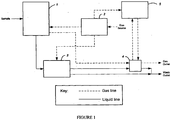
- FIG. 1 is a block schematic of one preferred embodiment of an apparatus according to this invention illustrating five component sub-assemblies 1 to 5.
- an aqueous sample is drawn into a sample-handling sub-assembly 1 of the apparatus, where the desired volumes of acid reagent and/or oxidizer reagent are added to a selected volume of sample.
- the sample may also be diluted at this stage with low-TOC dilution water if necessary before being passed to reactor sub-assembly 3 .
- sample, reagents and dilution water if any are mixed in the sample-handling portions of the apparatus to create a sample mixture comprising a substantially homogenous solution or suspension.
- the acidified sample mixture also is sparged with CO 2 -free gas provided by the gas control sub-assembly/module 2 .
- the flow rate of the sparge gas is controlled to ensure that IC in the sample is removed efficiently and substantially completely. If TC or IC is to be measured, the sample mixture is mixed but not sparged.
- a portion of the homogenous solution/suspension is then transferred to the reactor sub-assembly 3 .
- the solution/suspension containing oxidizer is heated in a sealed reactor to oxidize the organic compounds in the solution/suspension, and then it is cooled to near room temperature.
- oxidizer is not added to the solution/suspension. In this case, the solution/suspension may be warmed to facilitate conversion of bicarbonates and carbonates to CO 2 , but it is not heated so much that oxidation of organic compounds occurs.
- a stream of carrier gas from the gas control assembly/module 2 transfers the liquid and gas products in the reactor sub-assembly 3 to a gas/liquid separator sub-assembly/module 4 .
- the liquid exits the analyzer from the gas/liquid separator module 4 while the gas product, containing the CO 2 , flows to the NDIR detector sub-assembly 5 .
- the gas product and carrier gas mixture can be flowed through the gas/liquid separator module 4 , and vented to the atmosphere.
- FIG. 2 is a schematic showing the several fluidic components of the apparatus in more detail.
- sub-assemblies 1 to 5 as shown in Fig. 1 are delineated by broken lines.
- the sample-handling sub-assembly 1 comprises a syringe 6 that is connected through a three-way valve 7 to a coil of tubing 8 and a dilution water reservoir 9 containing low-TOC dilution water.
- a representative practice of the invention using the apparatus as illustrated in Fig. 2 is described below. It will be understood, however, that alternative sequences and methods for introducing the sample, reagent(s) and dilution water into the system could be used consistent with the scope of this invention. For example, using the apparatus illustrated in Fig.
- the oxidizer and acid reagents could be moved from coil 8 to a mixing location in the apparatus, such as to mixer/sparger 18 , prior to introducing the sample into the system in order to maintain a separation between these components until they are ready to be mixed at the mixing location.
- valve 7 and coil 8 contain only dilution water.
- the volume of coil 8 is designed and selected to be at least as large as, and preferably larger than, the volume of syringe 6 , so the only liquid that can enter the syringe is dilution water from coil 8 or reservoir 9 .
- valve 10 is open, and valves 11 , 12 , and 13 are closed.
- Syringe 6 starts filling with dilution water drawn from a syringe end of coil 8, which causes oxidizer reagent from oxidizer reagent reservoir 14 to be drawn through the six-way fluid element 17 and into a sample/reagent end of coil 8 .
- valve 10 closes.
- Valve 11 opens and syringe 6 draws additional dilution water from the syringe end of coil 8 into syringe 6 , which in turn draws the required volume of acid from acid reservoir 15 into the sample/reagent end of coil 8 , where it may partially mix with the oxidizer reagent already in this end of coil 8 .
- valve 11 closes, and valve 12 opens to allow the required volume of sample to be drawn into the sample/reagent end of coil 8 , as additional dilution water from the syringe end of coil 8 is drawn into syringe 6 .
- valve 12 closes.
- the coil 8 now contains the desired volumes of oxidizer, acid, and sample solution required for the measurement.
- Coil 8 may or may not contain a material amount of dilution water at this point, depending on the internal volume of coil 8 relative to the volumes of oxidizer, acid and sample drawn into coil 8 , and also depending upon whether or not the sample requires dilution prior to analysis.
- the source of the sample is a long distance from an analyzer, especially when the analyzer is used to monitor a process stream of an industrial operation.
- the analyzer could not provide real-time measurements if the only way of pumping the sample to the analyzer were the syringe pump. Therefore, in a preferred embodiment of the invention, the apparatus also includes a pump 16 which can rapidly draw a fresh portion of sample to the six-way union 17 . Once the new sample portion has been delivered to element 17 , it can be drawn into coil 8 quickly by further opening syringe 6 at the appropriate time.
- valve 13 The next step in the measurement method is to open valve 13 .
- the step of closing syringe 6 results in moving the liquids from coil 8 to a mixing location in the system, such as to the mixer/sparger component 18 , where the reagents, sample, and dilution water, if any, are thoroughly mixed. Particulate material in the sample is kept in suspension so that the solution/suspension is substantially homogeneous.
- the acid and oxidizer are first drawn into coil 8 and then are transferred into mixing/sparging chamber 18 .
- the sample and dilution water (if any) are then drawn into coil 8 and transferred into mixing/sparging chamber 18 where the sample, acid, oxidizer, and dilution water are mixed.
- Transferring the liquids to the mixing/sparging chamber 18 in two steps has the advantage of preventing premature reaction of IC in the sample with the acidic reagents in coil 8 .
- Generation of gas in coil 8 reduces the volume of sample drawn into coil 8 , adversely affecting the accuracy of the measurement.
- Mixer/sparger 18 includes a mixing and sparging chamber that also is designed to provide for sparging CO 2 -free gas through the solution/suspension to remove IC, if NPOC is to be measured.
- valve 19 opens to allow the sparge gas to bubble through the chamber element of mixer/sparger 18 .
- the gas can be provided from a pressurized gas cylinder (not shown) or from a pump (not shown) that draws ambient air through an absorber that purifies the air sufficiently for use as a CO 2 -free sparge gas, and/or as a carrier gas, and/or as a purge gas.
- the CO 2 -free gas is prepared for use in gas control sub-assembly module 2 .
- Sub-assembly 2 includes a pressure-regulating device 20 that adjusts the pressure of the gas to about 20 psig.
- a proportioning valve 21 controls the flow rate of the gas flowing through valve 19 by means of a sparge gas flow sensor 22 .
- a carrier gas flow sensor 23 in another conduit branch can be used to monitor and control the flow rate of the carrier gas to reactor sub-assembly 3 .
- a restrictor 24 in still another conduit branch can be used to provide for a small flow rate of purge gas to the NDIR detector.
- a valve (not shown) can be used to direct the gas that exits the chamber element of mixer/sparger 18 through the gas/liquid separator unit 4 and then to the NDIR sub-assembly 5 .
- This arrangement would allow the completeness of the sparging process to be monitored.
- the sparging is considered complete when the NDIR indicates that the concentration of CO 2 in the sparge gas going to the NDIR has decreased to a very small (negligible) value.
- valve 25 opens to allow all or a portion of the solution/suspension in the chamber element to be drawn into the interior of reactor 26 by pump 27 .
- High-pressure reactor inlet and outlet valves 28 and 29 respectively are open at this point.
- Valves 30 , 31 , 32 , and 33 are closed.
- the reactor heater 34 is off, and reactor 26 is near ambient temperature.
- Pump 27 operates until sufficient liquid from chamber 18 has passed through the interior of reactor 26 substantially to rinse out any remaining prior sample and to fill the reactor tube inside reactor 26 . At this point, pump 27 is stopped, and valves 25 , 28 , and 29 close.
- Reactor valves 28 and 29 are specially designed in accordance with this invention to allow the valve housings to be flushed after these valves are closed.
- the flushing step removes excess sample that contains CO 2 formed by the acidification of the IC in the sample. If this CO 2 were not flushed out of the valves, it would cause an error in the subsequent measurement.
- valves 30 and 31 are opened, and residual liquid and gases in these housings can then be pumped out by pump 27 and replaced by carrier gas.
- valve 31 closes and valve 32 opens to allow carrier gas to flow from sub-assembly 3 through valve 32 , pass through the gas/liquid separator 4 , and then pass to the NDIR detector sub-assembly 5 .
- Flow of carrier gas at this time is necessary to allow the NDIR detector to reach a steady baseline prior to the subsequent CO 2 measurement.
- An in-line filter 37 may be provided between gas/liquid separator 4 and the NDIR unit to prevent aerosols from the reactor 26 and/or from gas/liquid separator 4 from entering the optical path 39 of the NDIR detector.
- the organics contained in the sample portion in the reactor tube of reactor 26 must be oxidized.
- This oxidation can be made to occur by heating the interior of reactor 26 with a heater 34 , while controlling the temperature using a temperature sensor 35 .
- the sealed reactor can be heated, for example, to a temperature between about 150° C and 650° C (preferably between about 300° C and 400° C, and between about 350° C and 390° C in one preferred embodiment).
- the heating period may be between about one to thirty minutes, preferably between about two and four minutes, and approximately 3 minutes in one preferred embodiment. During this period, organics are oxidized in the sample portion in the reactor.
- heating element 34 is turned off, and fan unit 36 is turned on to blow ambient air over reactor 26 , cooling it rapidly to near room temperature. Because of the small mass of reactor 26 , it is typically cooled by this cooling step to near ambient temperature in less than about 90 seconds.
- the liquid inside reactor 26 is not oxidized.
- the reactor is filled as described above, but reactor 26 is heated only to a temperature sufficient to facilitate formation of CO 2 from bicarbonates and carbonates (i.e., typically to no more than about 100 °C).
- the subsequent cooling step may in this case be abbreviated or omitted entirely.
- the oxidizer reagent is not required for IC measurements, and its addition to the sample prior to the reactor step can thus be omitted to reduce operating cost and make the analysis faster.
- valves 30 and 32 close, and valves 28 , 29 , 31 , and 33 open.
- This apparatus configuration allows carrier gas to flow through the reactor tube of reactor 26 , and carry the reactor products through gas/liquid separator 4 , to the NDIR sub-assembly and along the NDIR optical path 39 .
- the NDIR measures the absorbance of the CO 2 in the gas flowing along NDIR optical path 39 at a wavelength of approximately 4.26 ⁇ m, e.g., 4.26 ⁇ m ⁇ 0.2 ⁇ m.
- the absorbance measurement begins at a baseline level, rises up to and passes through a maximum level, and then returns to the baseline level that existed before the valves associated with reactor 26 opened.
- Either the height of the absorbance peak (or the depth of the intensity trough) or the cone-shaped area of the absorbance response curve can be calibrated and used to determine the amount of CO 2 contained in the gas product coming from the reactor.
- the NDIR detector of this invention is comprised of three chambers, as seen in Figs. 2 and 6 .
- One chamber 38 contains the IR source.
- the central chamber which is the NDIR optical path 39 , is the chamber through which the carrier gas and the gas product from reactor 26 (which includes the CO 2 ) flow.
- the third chamber 40 contains the IR detector. Chambers 38 and 40 are flushed by CO 2 -free gas provided through the conduit that includes flow controller 24 so that CO 2 in the ambient air does not affect the measurements made with the NDIR.
- the NDIR further preferably includes an associated temperature sensor 41 and an associated pressure sensor 42 , proximately located relative to the NDIR, which monitors atmospheric pressure outside the NDIR (which is essentially the same as the pressure of the CO 2 in the NDIR).
- the temperature and pressure measurements made respectively by temperature sensor 41 and pressure sensor 42 can be used to compensate the response of the NDIR for variations in the temperature and pressure of the gas being measured.
- sensors 41 and/or 42 may be omitted if the measurement does not require temperature and/or pressure compensation.
- the mixer/sparger 18 includes a liquid inlet/gas outlet section 43 , a middle section 44 , and a liquid outlet/gas inlet section 45 .
- the top section 43 contains a liquid inlet 43a and the sparge gas outlet 43b .
- the bottom section 45 includes the inlet port 45b for the sparge gas and the outlet 45a for liquid.
- the middle section 44 includes a chamber element 44a located inside an annular solenoid coil 44b , which is activated by passing a series of current pulses through it. Such current waveform pulsing causes a magnetic stirrer 46 positioned inside chamber 44a to rapidly move up and down inside chamber 44a .
- the magnetic stirrer 46 is coated with a corrosion-resistant outer layer, and its up-and-down action under the influence of the solenoid-generated waveform pulses causes the sample, reagents and dilution water, if any, inside chamber 44a to be rapidly mixed, typically in about 60 seconds or less.
- the bottom section 45 of mixer/sparger 18 includes a porous gas disperser 47 , through which sparge gas is directed on its way into chamber 44a .
- the pore diameter in the gas disperser 47 may be about 1 ⁇ m to 3,175 mm, e.g., preferably about 5 ⁇ m to 50 ⁇ m, and about 18 ⁇ m in a preferred embodiment.
- the small bubbles produced by passing the sparge gas through disperser 47 results in efficient removal of IC from the liquid in chamber 44a , generally in about 10 seconds to 20 minutes at sparge gas flow rates ranging from about 50 to about 500 cc/min., typically and preferably in about one minute or less at a sparge gas flow rate of about 200 cc/min.
- a polymeric or elastic seal 48 is attached to or comprises a front end or section of a moveable plunger element 49 , which is designed to move back and forth inside the housing/valve body 50 when motor 51 is activated.
- the rear portion of seal 48 is adapted to retain first and second O-rings 52 and 53 respectively, which seal the interior of housing 50 .
- the front end of seal 48 is sized and shaped to mate with and plug an opening (i.e., an inlet opening or an outlet opening) of reactor 26 when the valve is closed by advancing plunger element 49 .
- Reactor 26 may be attached to valve housings 50 , for example, using fittings 70 (as seen in Fig. 4 ), which provide a seal that is essentially leak-free at the pressure produced in reactor 26 when the solution/suspension is sealed inside reactor 26 , and reactor 26 is heated.
- Seal 48 is enclosed by a seal chamber defined by the valve housing 50 extending from the sealed opening of reactor 26 at least to first O-ring 52 .
- This chamber can be continuously or periodically flushed with gas using seal chamber ports 54 and 55 as shown in Figure 4 .
- Reactor valves 28 and 29 also each have a third port that is not seen in Fig. 4 .
- the sample solution/suspension enters or exits the valve and the interior of reactor 26 through that third port.
- This apparatus configuration makes it possible to remove any IC or free CO 2 that may be present in the valve housing 50 while the sample is being oxidized/treated in reactor 26 .
- FIG. 5 is a schematic illustration of reactor valves 28 and 29 mounted at either end of a reactor 26 .
- the reactor heater element 34 has a tubular configuration open at both ends and located inside a heater housing with the reactor 26 mounted inside the tubular portion of heater 34 .
- heater 34 comprises a thick-film heating element deposited on an electrically insulating coating on the tubular portion of heater 34 , as shown in Figure 5 .
- the tubular portion of heater 34 may be constructed of stainless steel, titanium, or other suitable materials.
- the two ends of reactor 26 pass respectively through slots (not shown in Figure 5 ) in the sidewall of the tubular portion of heater 34 .
- reactor 26 is a tube constructed of titanium; however, stainless steel, ceramics, and other materials that are sufficiently corrosion-resistant and compatible with the oxidation temperatures of this invention can be used.
- the reactor assembly preferably also includes a fan component to cool the reactor after a heating/oxidation step.
- the outlet (downstream side) of fan 36 is preferably positioned close to one open end of the heater 34 , and is oriented so that a flow of cooling air during a cooling step passes through the heater housing and over both the exterior and interior of heater 34 , and also such that the airflow going through the interior of the tubular portion of the heater 34 during a cooling step passes over the portion of reactor 26 contained within the tubular portion of heater 34 .
- the special NDIR detector sub-assembly 5 is shown in greater detail in Fig. 6 .
- the NDIR consists of an optical system and an associated NDIR electronic system (as illustrated in the block diagram of Figure 7 ).
- the NDIR optical system has three major sections: an IR source compartment 38 , a sample cell/NDIR optical path 39 , and an IR detector compartment 40 .
- Collimating lenses 58 located at either end of sample cell 39 separate the adjacent sections.
- the lenses 58 are constructed of silicon.
- the IR source 56 is a thin-film heater. It may be mounted in plates 59 that are attached to an IR source heater and an IR source temperature sensor. Using the associated NDIR electronic system, the plates 59 and IR source 56 are controlled to a temperature of about 65 °C in one preferred embodiment.
- the IR detector 60 is a pyroelectric, lithium tantalate sensor element.
- a 4.26 ⁇ m filter is mounted in the IR detector in front of the sensor element. This filter selectively passes infrared radiation at the wavelength that is absorbed by CO 2 .
- the IR detector 60 measures the IR radiation that passes through the optical path 39 and the filter without being absorbed by CO 2 .
- the IR detector 60 may be mounted in plates 61 attached to an IR detector heater and an IR detector temperature sensor. In a preferred embodiment, the IR detector 60 is controlled at a temperature of about 55 °C using the associated NDIR electronic system.
- Carrier gas and the gas product from reactor 26 flow through the center section 39 of the NDIR.
- IR source 56 and IR detector 60 located in their separate compartments, are isolated from water vapor and potentially corrosive oxidation products by the compartment separation lenses 58 .
- the chambers 38 and 40 are also sealed, and CO 2 from ambient air is prevented from entering, or at least from remaining in, those chambers by flowing purge gas provided by the gas control sub-assembly 2 .
- the center section 39 of the NDIR has a gas inlet port 62 and a gas outlet port 63 , through which the carrier gas and the gas product from the reactor, including the CO 2 , flow.
- the gas inlet port 62 may be located proximate to the IR detector end of the NDIR, while the gas outlet port 63 is located proximate to the IR source end of the NDIR.
- the reverse orientation also is effective.
- the electronic system for operating the NDIR sub-assembly in a preferred invention embodiment is schematically illustrated in Fig. 7 .
- the electronic system includes electronic devices selected to provide power to the IR source, the IR source heater, the IR detector, the IR detector heater, and other electrical components.
- the electronics control system modulates the power to the IR source at a frequency of 55 Hz. Signals may be generated at other frequencies for operation of other components, such as the bandpass filter and analog-to-digital converter, from a field-programmable gate array (FPGA) as is known in the art.
- FPGA field-programmable gate array
- the FPGA can be adapted or adjusted to generate a 55 Hz clock for the IR source, with a duty cycle suitable for its operation.
- the IR source driver converts the logic-level clock signal into the pulsed power required by the IR source.
- the IR source emits infrared light, modulated at 55 Hz. This light reaches the IR detector, attenuated by any CO 2 present in the center section 39 of the NDIR.
- the IR detector converts the infrared light that it receives back into an electrical signal, with signal content at 55 Hz that is proportional to the infrared light that it receives.
- the detector bandpass filter is selected or adapted to remove harmonics of the 55 Hz signal and DC offset, low-frequency noise, and high-frequency noise generated by the IR detector.
- a synchronous circuit such as a switched-capacitor filter, is used in the detector bandpass filter, with a clock provided by the FPGA at a multiple of 55 Hz.
- the analog-to-digital converter samples the waveform from the detector bandpass filter, also using a clock provided by the FPGA at a whole number multiple of 55 Hz. For example, a clock of 5500 Hz provides 100 waveform samples per cycle of the IR detector waveform.
- the FPGA and the microprocessor perform further bandpass filtering of the digitized IR detector signal, centered at the modulation frequency of 55 Hz, to remove detector noise and noise from the AC mains at 50 Hz or 60 Hz. The amplitude of the 55 Hz signal at the output of the digital bandpass filter is then measured.
- the response of the IR detector is adjusted for temperature, pressure, and flow rate as necessary, and the CO 2 concentration is calculated in the manner described above. Based on the description provided herein, the processing steps described above could readily be implemented by one of ordinary skill in this art using an apparatus in accordance with this invention.
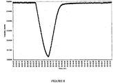
- Figure 8 illustrates a typical response curve of an NDIR during a carbon measurement sequence.
- the output is in instrument counts, and the counts are proportional to the amount of IR radiation that strikes the IR detector 60 .
- the response is at its maximum or baseline level.
- the response decreases until it reaches a minimum (trough) that corresponds to when the amount of CO 2 in section 39 has reached its maximum (maximum absorbance).
- the response returns to its original baseline level.
- the response peak can be used to calculate carbon concentrations in an aqueous sample being tested.
- the response curve can be mathematically integrated, and the resulting cone-shaped area of the response curve can be related to carbon concentration by one type of mathematical calibration correlation.
- the height of the peak can be measured and related to carbon concentration by another type of mathematical calibration correlation.
- These mathematical calibration correlations can be developed for a particular instrument by performing tests on samples containing known concentrations of IC, OC and/or TC. Basing computations on the measurement of peak height has the advantage that it is relatively unaffected by changes in gas flow rate; and, for that reason, this is the technique used.
Applications Claiming Priority (2)
| Application Number | Priority Date | Filing Date | Title |
|---|---|---|---|
| US96757607P | 2007-09-05 | 2007-09-05 | |
| PCT/US2008/010265 WO2009032205A2 (en) | 2007-09-05 | 2008-08-29 | Carbon measurement in aqueous samples using oxidation at elevated temperatures and pressures |
Publications (3)
| Publication Number | Publication Date |
|---|---|
| EP2185914A2 EP2185914A2 (en) | 2010-05-19 |
| EP2185914A4 EP2185914A4 (en) | 2013-12-04 |
| EP2185914B1 true EP2185914B1 (en) | 2019-10-09 |
Family
ID=40429607
Family Applications (1)
| Application Number | Title | Priority Date | Filing Date |
|---|---|---|---|
| EP08795705.6A Active EP2185914B1 (en) | 2007-09-05 | 2008-08-29 | Carbon measurement in aqueous samples using oxidation at elevated temperatures and pressures |
Country Status (5)
| Country | Link |
|---|---|
| US (5) | US8101417B2 (ja) |
| EP (1) | EP2185914B1 (ja) |
| JP (1) | JP5367710B2 (ja) |
| CN (1) | CN101796393B (ja) |
| WO (1) | WO2009032205A2 (ja) |
Families Citing this family (32)
| Publication number | Priority date | Publication date | Assignee | Title |
|---|---|---|---|---|
| CN101915723B (zh) * | 2010-07-21 | 2012-09-05 | 山东省科学院海洋仪器仪表研究所 | 水体中总有机碳的测量方法及装置 |
| KR101030931B1 (ko) | 2010-10-01 | 2011-04-27 | 구성테크닉스 주식회사 | 굴뚝의 배출가스 연속자동 측정 시스템 중 염화수소측정기 및 이를 사용한 배출가스의 측정방법 |
| JP5533641B2 (ja) * | 2010-12-27 | 2014-06-25 | 株式会社島津製作所 | 分析装置 |
| US20140190245A1 (en) * | 2011-06-22 | 2014-07-10 | 1St Detect Corporation | Reduced pressure liquid sampling |
| US20130333445A1 (en) * | 2012-06-04 | 2013-12-19 | Eif - Astute | Analyzer for fluids containing an inflammable substance and corresponding method |
| EP2893322B1 (en) * | 2012-08-20 | 2018-11-14 | SABIC Global Technologies B.V. | Real-time online determination of caustic in process scrubbers using near infrared spectroscopy and chemometrics |
| JP6155509B2 (ja) * | 2013-03-27 | 2017-07-05 | 大陽日酸株式会社 | 重酸素水の全有機体炭素の測定方法 |
| CN110068541A (zh) * | 2014-02-12 | 2019-07-30 | 积水医疗株式会社 | 碳同位素分析装置和碳同位素分析方法 |
| WO2015179871A1 (en) * | 2014-05-23 | 2015-11-26 | Hach Company | Measurement of total organic carbon |
| US9360466B2 (en) * | 2014-07-09 | 2016-06-07 | Shimadzu Corporation | Sample introduction mechanism for total organic carbon meter |
| US9878144B2 (en) * | 2014-10-14 | 2018-01-30 | Wilmarc Holdings, Llc | Connector system |
| DE102015118586A1 (de) | 2015-10-30 | 2017-05-04 | Lar Process Analysers Ag | Probenverdünnung |
| CN105759005A (zh) * | 2016-03-16 | 2016-07-13 | 浙江省计量科学研究院 | 一种催化超临界水氧化法在线检测水质总有机碳含量的方法及催化剂 |
| CN108801721A (zh) * | 2017-04-27 | 2018-11-13 | 中国科学院寒区旱区环境与工程研究所 | 一种水体中溶解的碳酸盐中稳定碳同位素分析前处理装置 |
| FR3068787B1 (fr) | 2017-07-10 | 2019-08-09 | Centre National De La Recherche Scientifique | Dispositif et methode d'analyse en continu de la concentration du carbone inorganique dissous (dic) et de ses compositions isotopiques en carbone et oxygene |
| JP7335869B2 (ja) * | 2017-08-07 | 2023-08-30 | オーアイ コーポレーション | 高温燃焼を使用した全有機体炭素分析装置(toca)のパルス注入技術による流れの停止 |
| CN111201433A (zh) * | 2017-08-24 | 2020-05-26 | 国立大学法人名古屋大学 | 光生成设备,碳同位素分析设备和采用碳同位素分析设备的碳同位素分析方法 |
| TWI667466B (zh) * | 2018-02-28 | 2019-08-01 | 總翔企業股份有限公司 | 水樣分析設備 |
| DE102018203842A1 (de) * | 2018-03-14 | 2019-09-19 | Robert Bosch Gmbh | Sensortag zur Detektion von Feinstaubpartikeln und Staubmaske |
| CN108828172A (zh) * | 2018-06-21 | 2018-11-16 | 中国计量科学研究院 | 总有机碳分析仪的校准方法和装置 |
| JP7211421B2 (ja) * | 2018-07-27 | 2023-01-24 | 株式会社島津製作所 | 分析装置 |
| US20220050070A1 (en) * | 2018-12-21 | 2022-02-17 | Shimadzu Corporation | Water quality analyzer |
| CN111474020A (zh) * | 2019-01-24 | 2020-07-31 | 应急管理部沈阳消防研究所 | 一种大批量灰烬样品成分分析的前处理装置和方法 |
| CN109738594B (zh) * | 2019-03-04 | 2023-09-01 | 中国科学院地球化学研究所 | 一种水热大腔体高温高压流动实验装置和实验方法 |
| CN109883788A (zh) * | 2019-03-21 | 2019-06-14 | 重庆地质矿产研究院 | 一种用于页岩有机碳测定的氧化装置 |
| JP6797317B1 (ja) * | 2019-03-22 | 2020-12-09 | 積水化学工業株式会社 | 有機物質製造システム |
| CN111856048A (zh) * | 2019-04-30 | 2020-10-30 | 中国石油化工股份有限公司 | 一种蚀变碳酸盐自动分析装置及分析方法 |
| CN110749778A (zh) * | 2019-10-21 | 2020-02-04 | 马鞍山钢铁股份有限公司 | 一种纯水脱气氢电导率的在线测量方法及测量装置 |
| CN115427805A (zh) * | 2019-12-11 | 2022-12-02 | Bl科技公司 | 通过电阻加热产生的高温高压的氧化测定含水样品中的碳 |
| CN111632569B (zh) * | 2020-05-24 | 2021-12-28 | 西安交通大学 | 一种用于超临界水氧化反应耦合的流动腐蚀-盐沉积装置 |
| JP2022044891A (ja) * | 2020-09-08 | 2022-03-18 | 株式会社ディスコ | 高圧エアーを利用する装置 |
| US20230204550A1 (en) * | 2021-03-12 | 2023-06-29 | Horiba, Ltd. | Elemental analysis device, method for operating elemental analysis device, and non-transitory computer readable medium storing program for operating elemental analysis device |
Citations (1)
| Publication number | Priority date | Publication date | Assignee | Title |
|---|---|---|---|---|
| EP0400965A2 (en) * | 1989-05-30 | 1990-12-05 | Takara Shuzo Co. Ltd. | Reagent reactor |
Family Cites Families (64)
| Publication number | Priority date | Publication date | Assignee | Title |
|---|---|---|---|---|
| US43499A (en) * | 1864-07-12 | Enoch hidden | ||
| US3296435A (en) | 1964-07-06 | 1967-01-03 | Dow Chemical Co | Method and apparatus for determining the total carbon content of aqueous systems |
| DE1648820C3 (de) | 1967-07-27 | 1976-01-02 | Bergwerksverband Gmbh, 4300 Essen | Gerät zur nichtdispersiven Ultrarot-Gasanalyse |
| US3964868A (en) * | 1974-05-24 | 1976-06-22 | Raytheon Company | Organic carbon analyzer system |
| US3958945A (en) | 1974-10-04 | 1976-05-25 | Envirotech Corporation | Sparging device |
| JPS5541836A (en) * | 1978-09-20 | 1980-03-24 | Hitachi Ltd | Liquid gas contact equipment having agitator blade |
| US4294799A (en) * | 1980-04-24 | 1981-10-13 | Beckman Instruments, Inc. | Temperature regulating apparatus |
| US4533641A (en) | 1982-07-21 | 1985-08-06 | Harbor Branch Foundation, Inc. | Automatic chemical analysis methods |
| US5047212A (en) | 1984-01-10 | 1991-09-10 | Anatel Corporation | Instrument for measurement of the organic carbon content of water |
| JPS60244838A (ja) * | 1984-05-21 | 1985-12-04 | Meito Sci Kk | 布帛の連続熱処理における汚れ防止方法 |
| US4619902A (en) | 1984-07-27 | 1986-10-28 | O.I. Corporation | Total organic carbon analyzer |
| JPH0628595B2 (ja) * | 1985-03-29 | 1994-04-20 | 株式会社日立製作所 | 培養装置 |
| JPH0726950B2 (ja) | 1986-11-28 | 1995-03-29 | トキコ株式会社 | 炭素量測定装置 |
| US4896971A (en) | 1987-03-26 | 1990-01-30 | General Signal Corporation | Mixing apparatus |
| US4902896A (en) | 1987-05-08 | 1990-02-20 | Mine Safety Appliances Company | Infrared fluid analyzer |
| JPS6421352A (en) | 1987-07-17 | 1989-01-24 | Hitachi Ltd | Reactor for underwater organic carbon analyzer |
| JPS6421354A (en) * | 1987-07-17 | 1989-01-24 | Tokico Ltd | Apparatus for measuring carbon quantity |
| JPH0718859B2 (ja) | 1987-07-17 | 1995-03-06 | トキコ株式会社 | 炭素量測定装置 |
| JPS6421355A (en) | 1987-07-17 | 1989-01-24 | Tokico Ltd | Apparatus for measuring carbon quantity |
| JPS6423156A (en) | 1987-07-20 | 1989-01-25 | Tokico Ltd | Carbon content measuring instrument |
| JPS6449958A (en) | 1987-08-19 | 1989-02-27 | Tokico Ltd | Instrument for measuring carbon content |
| JPS6449957A (en) | 1987-08-19 | 1989-02-27 | Tokico Ltd | Instrument for measuring carbon content |
| JPS6451131A (en) * | 1987-08-21 | 1989-02-27 | Fuji Denki Seisakusho Kk | Method and apparatus for stirring and mixing fluids |
| JP2582124B2 (ja) | 1988-06-20 | 1997-02-19 | トキコ株式会社 | 炭素量測定装置 |
| US4882098A (en) | 1988-06-20 | 1989-11-21 | General Signal Corporation | Mass transfer mixing system especially for gas dispersion in liquids or liquid suspensions |
| JPH01318955A (ja) | 1988-06-20 | 1989-12-25 | Tokico Ltd | 炭素量測定装置 |
| JPH0625757B2 (ja) | 1988-06-20 | 1994-04-06 | トキコ株式会社 | 炭素量測定装置 |
| US5232604A (en) | 1990-01-31 | 1993-08-03 | Modar, Inc. | Process for the oxidation of materials in water at supercritical temperatures utilizing reaction rate enhancers |
| JPH03259742A (ja) | 1990-03-09 | 1991-11-19 | Shimadzu Corp | 全有機炭素測定装置 |
| US5037067A (en) | 1990-10-29 | 1991-08-06 | Artek Industries, Inc. | High pressure rotary plug valve |
| JPH0580022A (ja) | 1991-06-13 | 1993-03-30 | Tokico Ltd | 炭素量測定装置 |
| EP0609431B1 (en) | 1992-08-24 | 1997-10-08 | Dade MicroScan Inc. | Sealable vessel for containing and processing analytical samples |
| JPH06167487A (ja) * | 1992-11-26 | 1994-06-14 | Shimadzu Corp | 全有機体炭素測定装置 |
| JP3265830B2 (ja) * | 1994-05-27 | 2002-03-18 | 株式会社島津製作所 | 全有機体炭素計 |
| US5482077A (en) | 1994-11-14 | 1996-01-09 | Minnesota Mining And Manufacturing Company | High pressure abrasive slurry check valve |
| US5531961A (en) * | 1995-02-10 | 1996-07-02 | Isco, Inc. | Water impurity analyzer |
| US5497003A (en) | 1995-02-15 | 1996-03-05 | Servo Corporation Of America | Pyroelectric detector array with optical filter elements |
| FI103216B (fi) | 1995-07-07 | 1999-05-14 | Vaisala Oyj | Menetelmä NDIR-mittalaitteen lyhyen Fabry-Perot interferometrin ohjaam iseksi |
| JPH09164328A (ja) * | 1995-12-15 | 1997-06-24 | Japan Organo Co Ltd | 超臨界水を反応媒体として用いるバッチ式反応容器内の反応圧力調整方法及び反応装置 |
| US5630444A (en) | 1996-04-24 | 1997-05-20 | Snap-Tite, Inc. | High pressure bellows valve |
| US5747809A (en) | 1996-06-11 | 1998-05-05 | Sri International | NDIR apparatus and method for measuring isotopic ratios in gaseous samples |
| WO1998022817A1 (en) * | 1996-11-18 | 1998-05-28 | Tekmar Company | Liquid sample carbon analyzer |
| JPH10160720A (ja) * | 1996-11-27 | 1998-06-19 | Tokico Ltd | 炭素量測定装置 |
| CN2307958Y (zh) | 1997-05-29 | 1999-02-17 | 苏永康 | 一种柱塞阀 |
| DE19727839A1 (de) * | 1997-06-24 | 1999-01-28 | Lar Analytik Und Umweltmestech | Verfahren zur Bestimmung eines Wasserinhaltsstoffes |
| JPH11101362A (ja) * | 1997-09-30 | 1999-04-13 | Anelva Corp | ガス切り替え弁及びこれを用いた真空装置のガスパージ機構 |
| US6114700A (en) | 1998-03-31 | 2000-09-05 | Anatel Corporation | NDIR instrument |
| US6447726B1 (en) * | 1998-08-10 | 2002-09-10 | Uab Research Foundation | High density protein crystal growth |
| US6142458A (en) | 1998-10-29 | 2000-11-07 | General Signal Corporation | Mixing system for dispersion of gas into liquid media |
| US6375900B1 (en) | 1999-04-27 | 2002-04-23 | Tekmar Company | Carbon analyzer with improved catalyst |
| JP2000356631A (ja) * | 1999-06-15 | 2000-12-26 | Japan Organo Co Ltd | 全有機体炭素測定方法及び装置 |
| US6622743B1 (en) * | 1999-08-09 | 2003-09-23 | Allied Healthcare Products, Inc. | Surge prevention device |
| JP4418854B2 (ja) * | 1999-10-29 | 2010-02-24 | 東北電力株式会社 | 有機廃棄物の処理方法 |
| JP4265080B2 (ja) * | 2000-05-10 | 2009-05-20 | 株式会社島津製作所 | 全有機体炭素計 |
| DE10150475B4 (de) * | 2001-10-16 | 2005-08-04 | Elementar Analysensysteme Gmbh | Reaktor und Verfahren zur Elementar-Analytik |
| US6988825B2 (en) | 2002-07-03 | 2006-01-24 | Bio/Data Corporation | Method and apparatus for using vertical magnetic stirring to produce turbulent and chaotic mixing in various states, without compromising components |
| US20040043499A1 (en) * | 2002-08-27 | 2004-03-04 | Maria Lee-Alvarez | Dissolved carbon measurement |
| DE10360066A1 (de) * | 2003-12-20 | 2005-07-21 | Dr. Bruno Lange Gmbh & Co. Kg | Verfahren zur fotometrischen Bestimmung eines Parameters |
| DE10360445A1 (de) | 2003-12-22 | 2005-07-28 | Lar Analytik & Umweltmesstechnik Gmbh | Verfahren und Anordnung zur Bestimmung von Wasserinhaltsstoffen |
| MX2007002213A (es) * | 2004-08-25 | 2007-05-04 | Environmental Syst Prod | Sistema y metodo para calibrar instrumentos detectores de emisiones remotas. |
| US7568361B2 (en) * | 2004-09-02 | 2009-08-04 | Eastman Chemical Company | Optimized liquid-phase oxidation |
| JP4679199B2 (ja) * | 2005-03-28 | 2011-04-27 | 日本曹達株式会社 | 脱ハロゲン化処理反応における温度制御方法及びそれに用いられる反応装置 |
| US8334141B2 (en) * | 2008-01-03 | 2012-12-18 | Baker Hughes Incorporated | Hydrate inhibition test loop |
| US20090175774A1 (en) * | 2008-01-03 | 2009-07-09 | Baker Hughes Incorporated | Hydrate inhibition test loop |
-
2008
- 2008-08-29 EP EP08795705.6A patent/EP2185914B1/en active Active
- 2008-08-29 US US12/733,276 patent/US8101417B2/en active Active
- 2008-08-29 CN CN2008801053206A patent/CN101796393B/zh active Active
- 2008-08-29 JP JP2010524000A patent/JP5367710B2/ja active Active
- 2008-08-29 WO PCT/US2008/010265 patent/WO2009032205A2/en active Application Filing
-
2010
- 2010-12-28 US US12/930,110 patent/US8101420B2/en active Active
- 2010-12-28 US US12/930,107 patent/US8101418B2/en active Active
- 2010-12-28 US US12/930,108 patent/US8114676B2/en active Active
- 2010-12-28 US US12/930,109 patent/US8101419B2/en active Active
Patent Citations (1)
| Publication number | Priority date | Publication date | Assignee | Title |
|---|---|---|---|---|
| EP0400965A2 (en) * | 1989-05-30 | 1990-12-05 | Takara Shuzo Co. Ltd. | Reagent reactor |
Also Published As
| Publication number | Publication date |
|---|---|
| US20110155270A1 (en) | 2011-06-30 |
| EP2185914A2 (en) | 2010-05-19 |
| CN101796393A (zh) | 2010-08-04 |
| US8114676B2 (en) | 2012-02-14 |
| US20100159602A1 (en) | 2010-06-24 |
| WO2009032205A3 (en) | 2009-05-14 |
| JP5367710B2 (ja) | 2013-12-11 |
| EP2185914A4 (en) | 2013-12-04 |
| JP2010538297A (ja) | 2010-12-09 |
| US20110155272A1 (en) | 2011-06-30 |
| US20110155912A1 (en) | 2011-06-30 |
| CN101796393B (zh) | 2013-06-19 |
| US20110163463A1 (en) | 2011-07-07 |
| US8101418B2 (en) | 2012-01-24 |
| US8101420B2 (en) | 2012-01-24 |
| WO2009032205A2 (en) | 2009-03-12 |
| US8101417B2 (en) | 2012-01-24 |
| US8101419B2 (en) | 2012-01-24 |
Similar Documents
| Publication | Publication Date | Title |
|---|---|---|
| EP2185914B1 (en) | Carbon measurement in aqueous samples using oxidation at elevated temperatures and pressures | |
| US8128874B2 (en) | Pressurized detectors substance analyzer | |
| EP3146315B1 (en) | Measurement of total organic carbon | |
| KR101723883B1 (ko) | 일체형 산화반응조를 구비한 총유기탄소 측정장치 및 측정방법 | |
| JP2000266677A (ja) | 窒素化合物、リン化合物及び有機汚濁物質の分析計 | |
| KR102278709B1 (ko) | Toc 측정 시스템의 수분 제거 및 건조 장치 | |
| KR101809021B1 (ko) | 전도도법 검출방식의 총유기탄소 측정 센서 및 이를 이용한 총유기탄소 검출 시스템 | |
| KR102414181B1 (ko) | 총유기탄소 측정장치 | |
| US20230012945A1 (en) | Carbon measurements in aqueous samples using oxidation at elevated temperatures and pressures created by resistive heating | |
| JP3896795B2 (ja) | 窒素濃度測定装置 | |
| JP2001124757A (ja) | 3態窒素分析システムにおけるシステムの自己診断方法 | |
| JP2004361244A (ja) | ガス濃度分析器、およびそれを用いたガス濃度分析方法 | |
| JPH06288923A (ja) | 水中のシリカ成分の分析装置 | |
| JP3911820B2 (ja) | イオン濃度計測装置 | |
| JP3237400B2 (ja) | 水中の窒素化合物及びリン化合物の分析装置 | |
| JP3911821B2 (ja) | イオン濃度計測装置 | |
| JPH1010050A (ja) | 三態窒素計の気化分離器 | |
| KR20240016689A (ko) | 다중채널을 갖는 ndir 센서 및 이를 포함하는 toc 측정 시스템 | |
| KR20230050514A (ko) | Toc 측정시스템의 분석 오차 보정방법 | |
| JP2019002809A (ja) | 除去部材、校正装置、及びガス分析装置 | |
| JP2001091506A (ja) | 全有機炭素計 |
Legal Events
| Date | Code | Title | Description |
|---|---|---|---|
| PUAI | Public reference made under article 153(3) epc to a published international application that has entered the european phase |
Free format text: ORIGINAL CODE: 0009012 |
|
| 17P | Request for examination filed |
Effective date: 20100317 |
|
| AK | Designated contracting states |
Kind code of ref document: A2 Designated state(s): AT BE BG CH CY CZ DE DK EE ES FI FR GB GR HR HU IE IS IT LI LT LU LV MC MT NL NO PL PT RO SE SI SK TR |
|
| AX | Request for extension of the european patent |
Extension state: AL BA MK RS |
|
| DAX | Request for extension of the european patent (deleted) | ||
| A4 | Supplementary search report drawn up and despatched |
Effective date: 20131107 |
|
| RIC1 | Information provided on ipc code assigned before grant |
Ipc: G01N 33/18 20060101ALI20131031BHEP Ipc: G01N 21/35 20060101AFI20131031BHEP |
|
| 17Q | First examination report despatched |
Effective date: 20140704 |
|
| STAA | Information on the status of an ep patent application or granted ep patent |
Free format text: STATUS: EXAMINATION IS IN PROGRESS |
|
| REG | Reference to a national code |
Ref country code: DE Ref legal event code: R079 Ref document number: 602008061382 Country of ref document: DE Free format text: PREVIOUS MAIN CLASS: G01N0021350000 Ipc: G01N0033180000 |
|
| RIC1 | Information provided on ipc code assigned before grant |
Ipc: G01N 31/12 20060101ALI20190318BHEP Ipc: G01N 33/18 20060101AFI20190318BHEP Ipc: G01N 21/3504 20140101ALI20190318BHEP |
|
| GRAP | Despatch of communication of intention to grant a patent |
Free format text: ORIGINAL CODE: EPIDOSNIGR1 |
|
| STAA | Information on the status of an ep patent application or granted ep patent |
Free format text: STATUS: GRANT OF PATENT IS INTENDED |
|
| INTG | Intention to grant announced |
Effective date: 20190426 |
|
| GRAS | Grant fee paid |
Free format text: ORIGINAL CODE: EPIDOSNIGR3 |
|
| GRAA | (expected) grant |
Free format text: ORIGINAL CODE: 0009210 |
|
| STAA | Information on the status of an ep patent application or granted ep patent |
Free format text: STATUS: THE PATENT HAS BEEN GRANTED |
|
| AK | Designated contracting states |
Kind code of ref document: B1 Designated state(s): AT BE BG CH CY CZ DE DK EE ES FI FR GB GR HR HU IE IS IT LI LT LU LV MC MT NL NO PL PT RO SE SI SK TR |
|
| REG | Reference to a national code |
Ref country code: GB Ref legal event code: FG4D |
|
| REG | Reference to a national code |
Ref country code: CH Ref legal event code: EP |
|
| REG | Reference to a national code |
Ref country code: DE Ref legal event code: R096 Ref document number: 602008061382 Country of ref document: DE |
|
| REG | Reference to a national code |
Ref country code: IE Ref legal event code: FG4D |
|
| REG | Reference to a national code |
Ref country code: AT Ref legal event code: REF Ref document number: 1189420 Country of ref document: AT Kind code of ref document: T Effective date: 20191115 |
|
| REG | Reference to a national code |
Ref country code: NL Ref legal event code: MP Effective date: 20191009 |
|
| REG | Reference to a national code |
Ref country code: LT Ref legal event code: MG4D |
|
| REG | Reference to a national code |
Ref country code: AT Ref legal event code: MK05 Ref document number: 1189420 Country of ref document: AT Kind code of ref document: T Effective date: 20191009 |
|
| PG25 | Lapsed in a contracting state [announced via postgrant information from national office to epo] |
Ref country code: LT Free format text: LAPSE BECAUSE OF FAILURE TO SUBMIT A TRANSLATION OF THE DESCRIPTION OR TO PAY THE FEE WITHIN THE PRESCRIBED TIME-LIMIT Effective date: 20191009 Ref country code: PL Free format text: LAPSE BECAUSE OF FAILURE TO SUBMIT A TRANSLATION OF THE DESCRIPTION OR TO PAY THE FEE WITHIN THE PRESCRIBED TIME-LIMIT Effective date: 20191009 Ref country code: NO Free format text: LAPSE BECAUSE OF FAILURE TO SUBMIT A TRANSLATION OF THE DESCRIPTION OR TO PAY THE FEE WITHIN THE PRESCRIBED TIME-LIMIT Effective date: 20200109 Ref country code: NL Free format text: LAPSE BECAUSE OF FAILURE TO SUBMIT A TRANSLATION OF THE DESCRIPTION OR TO PAY THE FEE WITHIN THE PRESCRIBED TIME-LIMIT Effective date: 20191009 Ref country code: AT Free format text: LAPSE BECAUSE OF FAILURE TO SUBMIT A TRANSLATION OF THE DESCRIPTION OR TO PAY THE FEE WITHIN THE PRESCRIBED TIME-LIMIT Effective date: 20191009 Ref country code: SE Free format text: LAPSE BECAUSE OF FAILURE TO SUBMIT A TRANSLATION OF THE DESCRIPTION OR TO PAY THE FEE WITHIN THE PRESCRIBED TIME-LIMIT Effective date: 20191009 Ref country code: LV Free format text: LAPSE BECAUSE OF FAILURE TO SUBMIT A TRANSLATION OF THE DESCRIPTION OR TO PAY THE FEE WITHIN THE PRESCRIBED TIME-LIMIT Effective date: 20191009 Ref country code: FI Free format text: LAPSE BECAUSE OF FAILURE TO SUBMIT A TRANSLATION OF THE DESCRIPTION OR TO PAY THE FEE WITHIN THE PRESCRIBED TIME-LIMIT Effective date: 20191009 Ref country code: BG Free format text: LAPSE BECAUSE OF FAILURE TO SUBMIT A TRANSLATION OF THE DESCRIPTION OR TO PAY THE FEE WITHIN THE PRESCRIBED TIME-LIMIT Effective date: 20200109 Ref country code: GR Free format text: LAPSE BECAUSE OF FAILURE TO SUBMIT A TRANSLATION OF THE DESCRIPTION OR TO PAY THE FEE WITHIN THE PRESCRIBED TIME-LIMIT Effective date: 20200110 Ref country code: PT Free format text: LAPSE BECAUSE OF FAILURE TO SUBMIT A TRANSLATION OF THE DESCRIPTION OR TO PAY THE FEE WITHIN THE PRESCRIBED TIME-LIMIT Effective date: 20200210 Ref country code: ES Free format text: LAPSE BECAUSE OF FAILURE TO SUBMIT A TRANSLATION OF THE DESCRIPTION OR TO PAY THE FEE WITHIN THE PRESCRIBED TIME-LIMIT Effective date: 20191009 |
|
| PG25 | Lapsed in a contracting state [announced via postgrant information from national office to epo] |
Ref country code: IS Free format text: LAPSE BECAUSE OF FAILURE TO SUBMIT A TRANSLATION OF THE DESCRIPTION OR TO PAY THE FEE WITHIN THE PRESCRIBED TIME-LIMIT Effective date: 20200224 Ref country code: HR Free format text: LAPSE BECAUSE OF FAILURE TO SUBMIT A TRANSLATION OF THE DESCRIPTION OR TO PAY THE FEE WITHIN THE PRESCRIBED TIME-LIMIT Effective date: 20191009 |
|
| REG | Reference to a national code |
Ref country code: DE Ref legal event code: R097 Ref document number: 602008061382 Country of ref document: DE |
|
| PG2D | Information on lapse in contracting state deleted |
Ref country code: IS |
|
| PG25 | Lapsed in a contracting state [announced via postgrant information from national office to epo] |
Ref country code: RO Free format text: LAPSE BECAUSE OF FAILURE TO SUBMIT A TRANSLATION OF THE DESCRIPTION OR TO PAY THE FEE WITHIN THE PRESCRIBED TIME-LIMIT Effective date: 20191009 Ref country code: CZ Free format text: LAPSE BECAUSE OF FAILURE TO SUBMIT A TRANSLATION OF THE DESCRIPTION OR TO PAY THE FEE WITHIN THE PRESCRIBED TIME-LIMIT Effective date: 20191009 Ref country code: EE Free format text: LAPSE BECAUSE OF FAILURE TO SUBMIT A TRANSLATION OF THE DESCRIPTION OR TO PAY THE FEE WITHIN THE PRESCRIBED TIME-LIMIT Effective date: 20191009 Ref country code: DK Free format text: LAPSE BECAUSE OF FAILURE TO SUBMIT A TRANSLATION OF THE DESCRIPTION OR TO PAY THE FEE WITHIN THE PRESCRIBED TIME-LIMIT Effective date: 20191009 Ref country code: IS Free format text: LAPSE BECAUSE OF FAILURE TO SUBMIT A TRANSLATION OF THE DESCRIPTION OR TO PAY THE FEE WITHIN THE PRESCRIBED TIME-LIMIT Effective date: 20200209 |
|
| PLBE | No opposition filed within time limit |
Free format text: ORIGINAL CODE: 0009261 |
|
| STAA | Information on the status of an ep patent application or granted ep patent |
Free format text: STATUS: NO OPPOSITION FILED WITHIN TIME LIMIT |
|
| PG25 | Lapsed in a contracting state [announced via postgrant information from national office to epo] |
Ref country code: IT Free format text: LAPSE BECAUSE OF FAILURE TO SUBMIT A TRANSLATION OF THE DESCRIPTION OR TO PAY THE FEE WITHIN THE PRESCRIBED TIME-LIMIT Effective date: 20191009 Ref country code: SK Free format text: LAPSE BECAUSE OF FAILURE TO SUBMIT A TRANSLATION OF THE DESCRIPTION OR TO PAY THE FEE WITHIN THE PRESCRIBED TIME-LIMIT Effective date: 20191009 |
|
| 26N | No opposition filed |
Effective date: 20200710 |
|
| PG25 | Lapsed in a contracting state [announced via postgrant information from national office to epo] |
Ref country code: SI Free format text: LAPSE BECAUSE OF FAILURE TO SUBMIT A TRANSLATION OF THE DESCRIPTION OR TO PAY THE FEE WITHIN THE PRESCRIBED TIME-LIMIT Effective date: 20191009 |
|
| PG25 | Lapsed in a contracting state [announced via postgrant information from national office to epo] |
Ref country code: MC Free format text: LAPSE BECAUSE OF FAILURE TO SUBMIT A TRANSLATION OF THE DESCRIPTION OR TO PAY THE FEE WITHIN THE PRESCRIBED TIME-LIMIT Effective date: 20191009 |
|
| REG | Reference to a national code |
Ref country code: CH Ref legal event code: PL |
|
| PG25 | Lapsed in a contracting state [announced via postgrant information from national office to epo] |
Ref country code: LI Free format text: LAPSE BECAUSE OF NON-PAYMENT OF DUE FEES Effective date: 20200831 Ref country code: CH Free format text: LAPSE BECAUSE OF NON-PAYMENT OF DUE FEES Effective date: 20200831 Ref country code: LU Free format text: LAPSE BECAUSE OF NON-PAYMENT OF DUE FEES Effective date: 20200829 |
|
| REG | Reference to a national code |
Ref country code: BE Ref legal event code: MM Effective date: 20200831 |
|
| PG25 | Lapsed in a contracting state [announced via postgrant information from national office to epo] |
Ref country code: BE Free format text: LAPSE BECAUSE OF NON-PAYMENT OF DUE FEES Effective date: 20200831 Ref country code: IE Free format text: LAPSE BECAUSE OF NON-PAYMENT OF DUE FEES Effective date: 20200829 |
|
| PG25 | Lapsed in a contracting state [announced via postgrant information from national office to epo] |
Ref country code: TR Free format text: LAPSE BECAUSE OF FAILURE TO SUBMIT A TRANSLATION OF THE DESCRIPTION OR TO PAY THE FEE WITHIN THE PRESCRIBED TIME-LIMIT Effective date: 20191009 Ref country code: MT Free format text: LAPSE BECAUSE OF FAILURE TO SUBMIT A TRANSLATION OF THE DESCRIPTION OR TO PAY THE FEE WITHIN THE PRESCRIBED TIME-LIMIT Effective date: 20191009 Ref country code: CY Free format text: LAPSE BECAUSE OF FAILURE TO SUBMIT A TRANSLATION OF THE DESCRIPTION OR TO PAY THE FEE WITHIN THE PRESCRIBED TIME-LIMIT Effective date: 20191009 |
|
| P01 | Opt-out of the competence of the unified patent court (upc) registered |
Effective date: 20230521 |
|
| PGFP | Annual fee paid to national office [announced via postgrant information from national office to epo] |
Ref country code: GB Payment date: 20230828 Year of fee payment: 16 |
|
| PGFP | Annual fee paid to national office [announced via postgrant information from national office to epo] |
Ref country code: FR Payment date: 20230825 Year of fee payment: 16 Ref country code: DE Payment date: 20230829 Year of fee payment: 16 |