EP2183544B1 - Appareil et procédé de mesure sans contact - Google Patents
Appareil et procédé de mesure sans contact Download PDFInfo
- Publication number
- EP2183544B1 EP2183544B1 EP08788327.8A EP08788327A EP2183544B1 EP 2183544 B1 EP2183544 B1 EP 2183544B1 EP 08788327 A EP08788327 A EP 08788327A EP 2183544 B1 EP2183544 B1 EP 2183544B1
- Authority
- EP
- European Patent Office
- Prior art keywords
- image
- optical pattern
- projector
- images
- perspective
- Prior art date
- Legal status (The legal status is an assumption and is not a legal conclusion. Google has not performed a legal analysis and makes no representation as to the accuracy of the status listed.)
- Not-in-force
Links
Images


Classifications
-
- G—PHYSICS
- G01—MEASURING; TESTING
- G01B—MEASURING LENGTH, THICKNESS OR SIMILAR LINEAR DIMENSIONS; MEASURING ANGLES; MEASURING AREAS; MEASURING IRREGULARITIES OF SURFACES OR CONTOURS
- G01B11/00—Measuring arrangements characterised by the use of optical techniques
- G01B11/002—Measuring arrangements characterised by the use of optical techniques for measuring two or more coordinates
- G01B11/005—Measuring arrangements characterised by the use of optical techniques for measuring two or more coordinates coordinate measuring machines
- G01B11/007—Measuring arrangements characterised by the use of optical techniques for measuring two or more coordinates coordinate measuring machines feeler heads therefor
-
- G—PHYSICS
- G01—MEASURING; TESTING
- G01B—MEASURING LENGTH, THICKNESS OR SIMILAR LINEAR DIMENSIONS; MEASURING ANGLES; MEASURING AREAS; MEASURING IRREGULARITIES OF SURFACES OR CONTOURS
- G01B11/00—Measuring arrangements characterised by the use of optical techniques
- G01B11/02—Measuring arrangements characterised by the use of optical techniques for measuring length, width or thickness
- G01B11/026—Measuring arrangements characterised by the use of optical techniques for measuring length, width or thickness by measuring distance between sensor and object
-
- G—PHYSICS
- G01—MEASURING; TESTING
- G01B—MEASURING LENGTH, THICKNESS OR SIMILAR LINEAR DIMENSIONS; MEASURING ANGLES; MEASURING AREAS; MEASURING IRREGULARITIES OF SURFACES OR CONTOURS
- G01B11/00—Measuring arrangements characterised by the use of optical techniques
- G01B11/24—Measuring arrangements characterised by the use of optical techniques for measuring contours or curvatures
- G01B11/25—Measuring arrangements characterised by the use of optical techniques for measuring contours or curvatures by projecting a pattern, e.g. one or more lines, moiré fringes on the object
- G01B11/2518—Projection by scanning of the object
- G01B11/2527—Projection by scanning of the object with phase change by in-plane movement of the patern
-
- G—PHYSICS
- G06—COMPUTING; CALCULATING OR COUNTING
- G06T—IMAGE DATA PROCESSING OR GENERATION, IN GENERAL
- G06T7/00—Image analysis
- G06T7/0002—Inspection of images, e.g. flaw detection
- G06T7/0004—Industrial image inspection
-
- G—PHYSICS
- G06—COMPUTING; CALCULATING OR COUNTING
- G06T—IMAGE DATA PROCESSING OR GENERATION, IN GENERAL
- G06T7/00—Image analysis
- G06T7/50—Depth or shape recovery
- G06T7/521—Depth or shape recovery from laser ranging, e.g. using interferometry; from the projection of structured light
-
- G—PHYSICS
- G06—COMPUTING; CALCULATING OR COUNTING
- G06T—IMAGE DATA PROCESSING OR GENERATION, IN GENERAL
- G06T7/00—Image analysis
- G06T7/50—Depth or shape recovery
- G06T7/55—Depth or shape recovery from multiple images
- G06T7/593—Depth or shape recovery from multiple images from stereo images
-
- G—PHYSICS
- G06—COMPUTING; CALCULATING OR COUNTING
- G06T—IMAGE DATA PROCESSING OR GENERATION, IN GENERAL
- G06T2207/00—Indexing scheme for image analysis or image enhancement
- G06T2207/30—Subject of image; Context of image processing
- G06T2207/30108—Industrial image inspection
- G06T2207/30164—Workpiece; Machine component
Definitions
- This invention relates to a method and apparatus for measuring an object without contacting the object.
- Photogrammetry is a known technique for determining the location of certain points on an object from photographs taken at different perspectives, i.e. from different positions and/or orientations.
- photogrammetry comprises obtaining at least two images of an object taken from two different perspectives. For each image the two dimensional coordinates of a feature of the object on the image is determined. It is then possible from the knowledge of the location and orientation of the camera(s) which took the images, and the points at which the feature is formed on the images to determine the three dimensional coordinates of the feature on the object.
- Such a technique is disclosed for example in US 5,251,156 .
- Known techniques for identifying features include attaching targets to points of interest on the object. For example, coded “bull's eyes”, wherein each "bull's-eye” has a unique central point which is invariant with perspective, surrounded by a set of concentric black and white rings which code a unique identifier, can be placed on features of an object to be measured. It is also known to project target features onto the object, for instance by projecting a spot or bull's eye onto the surface of the object. Automatic feature recognition methods can be used to both locate the centre of the target and also decode the unique identifier if present. By means of such targets the images can be automatically analysed and the coordinates of the "bull's-eye" centres returned.
- SCHARSTEIN D ET AL "High-accuracy stereo depth maps using structured light"
- XP010644898 discloses a photogrammetric technique in which structured light is used to uniquely label each pixel in a set of acquired images.
- a series of structured light images are projected onto an object and then the set of projected intensities are decoded at each pixel to give it a unique label.
- Such feature recognition techniques include the Hough Transform which can be used to identify straight lines, circles and ellipses. This technique can be used to identify more complex shapes, but the computation required can be demanding and the results can be sensitive to noise and lighting artefacts in the images.
- the invention provides a method for inspecting an object using photogrammetry in which irregularities in an optical pattern projected on the object are identified and used as target features.
- target features can be identified without the use of markers which are placed or projected on the object. Rather, they are created by the interface between the object and optical pattern, the object deforming the optical pattern imaged thereby creating irregularities in the optical pattern. This enables highly accurate measurements of the object to be taken quickly. It also enables a high density of points to be targeted and measured. It has also been found that the method of the invention can require less processing resources to identify points on complex shaped objects than by other known image processing techniques.
- At least one of the relative position and relative orientation of the object and projector of the optical pattern at step i) can be different to that of the object and projector of the optical pattern at step ii).
- the relative position and/or orientation of the object and projector of the optical pattern at step i) can be different to the relative position and/or orientation of the object and projector of the optical pattern at step ii) the relative perspective between the object and projector of the optical pattern can be different between the steps. Accordingly, this can result in the position of the optical pattern on the object being altered between obtaining the first and at least second images. Accordingly, the position of the optical pattern on the object can be different for each image. Altering the position of the optical pattern on the object can be advantageous as it can avoid problems caused by shadowing or obstruction of the optical pattern.
- the optical pattern can extend in two dimensions.
- the optical pattern projected can enable the determination of the topology of the surface of an object in two dimensions from a single image of the optical pattern on the object.
- the optical pattern can be a substantially full-field optical pattern.
- a substantially full-field optical pattern can be one in which the pattern extends over at least 50% of the field of view of an image sensor for obtaining at least one of the first and second images at a reference plane (described in more detail below), more preferably over at least 75%, especially preferably over at least 95%, for example substantially over the entire field of view of the image sensor at a reference plane.
- the reference plane can be a plane that is a known distance away from the image sensor.
- the reference plane can be a plane which contains the point at which the optical pattern projector's and image sensor's optical axes intersect.
- the reference plane can extend perpendicular to the image sensor's optical axis.
- the pattern as imaged in the at least one first and at least one second image is projected over an area of the object.
- the pattern extends over an area of the object so as to facilitate the measurement of a plurality of points of the object over the area from the at least one first and at least one second images using the method of the present invention.
- the pattern need not be repetitive. However, preferably the pattern is a substantially repetitive pattern.
- Particularly preferred optical patterns comprise substantially periodic optical patterns.
- a periodic optical pattern can be a pattern which repeats after a certain finite distance. The minimum distance between repetitions can be the period of the pattern.
- the optical pattern is periodic in at least one dimension.
- the optical pattern can be periodic in at least two perpendicular dimensions.
- Suitable optical patterns for use with the present invention include patterns of concentric circles, patterns of lines of varying colour, shades, and/or tones.
- the colour, shades and/or tones could alternate between two or more different values.
- the colour, shade and/or tones could vary between a plurality of discrete values.
- the colour, shade and/or tones varies continuously across the optical pattern.
- the optical pattern is a fringe pattern.
- the optical pattern can be a set of sinusoidal fringes.
- the optical pattern can be in the infrared to ultraviolet range.
- the optical pattern is a visible optical pattern.
- an optical pattern for use in methods such as that of the present invention is also commonly referred to as a structured light pattern.
- Suitable projectors for the optical pattern include a digital light projector configured to project an image input from a processor device. Such a projector enables the pattern projected to be changed.
- Suitable projectors could comprise a light source and one or more diffraction gratings arranged to produce the optical pattern.
- the diffraction grating(s) could be moveable so as to enable the pattern projected by the projector to be changed.
- the diffraction grating(s) can be mounted on a piezoelectric transducer.
- the diffraction gratings could be fixed such that the pattern projected by the projector cannot be changed.
- the projector could comprise a light source and a hologram.
- the projector could comprise a light source and a patterned slide. Further still, the projector could comprise two mutually coherent light sources.
- the coherent light sources could be moveable so as to enable the pattern projected by the projector to be changed.
- the coherent light sources can be mounted on a piezoelectric transducer.
- the coherent light sources could be fixed such that the pattern projected by the projector cannot be changed.
- the first and second images contain at least partially overlapping views of the object. This is so that at least one common object feature is present in both of the images.
- a common object feature can be any feature on the object which has been captured in the first and second image.
- the common object feature could be a single point on the object - for instance a corner feature.
- the common object feature could be a plurality of points on the object.
- the common object feature could be a line, such as an elongate edge of an object. The line could be straight or curved.
- the common object feature could be used as a target feature. In particular the common object feature could be used as a target feature in a photogrammetric measurement process.
- At least first and second optical pattern projectors having different positions and/or orientations relative to the object can be provided. Accordingly, the optical pattern imaged in the first image can be projected by a first optical pattern projector and the optical pattern imaged in the second image can be projected by a second optical pattern projector.
- the projector of the optical pattern imaged at step i) and the projector of the optical pattern imaged at step ii) are provided by a common optical pattern projector unit comprising at least one optical pattern projector.
- the method can comprise relatively moving the object and the optical pattern projector unit between steps i) and ii). In particular this can comprise moving the optical pattern projector unit relative to the object.
- the optical pattern projector unit could comprise a plurality of optical pattern projectors. The plurality of optical pattern projectors could be in a fixed spatial relationship relative to each other.
- the projector of the optical pattern imaged at step ii) is the projector of the optical pattern imaged at step i). Accordingly, the method can be performed with a single optical pattern projector only. Therefore the optical pattern projector unit can comprise a single optical pattern projector only. This can be simpler than providing a plurality of optical pattern projectors. Accordingly, the method can further comprise relatively moving the object and the projector of the optical pattern between steps i) and ii). In particular, the method can comprise moving the projector of the optical pattern relative to the object.
- the type of optical pattern projected on the object in step i) can be different to the type of optical pattern projected in step ii).
- the optical pattern projected in step i) can be a plurality of concentric circles and the optical pattern projected in step ii) can be a plurality of straight lines.
- the optical pattern projected on the object in step i) and step ii) is the same.
- the at least one first image and the at least one second image can be obtained by at least one suitable imaging device.
- suitable imaging devices can comprise at least one image sensor.
- suitable imaging devices can comprise an optical electromagnetic radiation (EMR) sensitive detector, such as a charge-coupled device (CCD), a complementary metal-oxide-semiconductor (CMOS).
- EMR electromagnetic radiation
- CCD charge-coupled device
- CMOS complementary metal-oxide-semiconductor
- Suitable imaging devices can be optically configured to focus light at the image plane.
- the image plane can be defined by the image sensor.
- suitable imaging devices can comprise at least one optical component configured to focus optical EMR at the image plane.
- the at least one optical component comprises a lens.
- Suitable imaging devices can be based on the pinhole camera model which consists of a pinhole, which can also be referred to as the imaging device's perspective centre, through which optical EMR rays are assumed to pass before intersecting with the image plane.
- imaging devices that do not comprise a pinhole but instead comprise a lens to focus optical EMR also have a perspective centre and this can be the point through which all optical EMR rays that intersect with the image plane are assumed to pass.
- the perspective centre can be found relative to the image sensor using a calibration procedure, such as those described in J. Heikkila and O. Silven, "A four-step camera calibration procedure with implicit image correction", Proceedings of the 1997 Conference in Computer Vision and Pattern Recognition (CVPR '97) and J.G Fryer, "Camera Calibration” in K. B. Atkinson (ed.) "Close range photogrammetry and machine vision", Whittles publishing (1996 ). Correction parameters such as those for correcting lens aberrations can be provided and are well known and are for instance described in these two documents.
- the at least one first image and the at least one second image are obtained by a common imaging device unit comprising at least one imaging device.
- the method can further comprise relatively moving the imaging device unit and object from the first perspective to the second perspective.
- the movement of the object and/or imaging device unit could be performed manually or automatically.
- the imaging device unit can comprise a plurality of imaging devices.
- the at least one first and at least one second images can be obtained by a single imaging device.
- the single imaging device can comprise a single image sensor. Accordingly, the at least one first and at least second images can be obtained by a single image sensor. Accordingly, the object could be moved between the step of obtaining the at least one first image and at least one second image in order to obtain the first and second perspectives.
- the imaging device could be moved between the step of obtaining the at least one first image and at least one second image in order to obtain the first and second perspectives.
- the method can comprise moving the imaging device from the first known perspective to the second known perspective.
- the optical pattern projector unit and the imaging device unit are mounted on a coordinate positioning apparatus.
- the optical pattern projector unit and the imaging device unit are mounted on a coordinate positioning apparatus such that they can be moved in at least one linear degree of freedom, more preferably at least two linear degrees of freedom, especially preferably at least three linear degrees of freedom.
- the linear degrees of freedom are perpendicular to each other.
- the optical pattern projector unit and the imaging device unit are mounted on a coordinate positioning apparatus such that they can be rotated through at least one rotational degree of freedom, more preferably rotated through at least two rotational degrees of freedom, for example through at least three rotational degrees of freedom.
- the coordinate positioning apparatus is a computer controlled coordinate positioning apparatus, for example a computer numerically controlled (CNC) coordinate positioning apparatus.
- Suitable coordinate positioning apparatus include coordinate measuring machines (CMM) and machine tools.
- the at least one projector of the optical pattern in steps i) and ii) and the at least one imaging device for obtaining the first and second images are in a fixed spatial relationship relative to each other. Accordingly, they can be provided as a single unit. In particular they can be provided as common probe device.
- the common probe device can be mounted on a coordinate positioning apparatus. This can provide easy manipulation and position determination. In particular, it enables multiple known positions and orientations of the optical pattern projector unit and/or the image sensor unit to be achieved quickly, increasing the accuracy and speed of measuring the object.
- the method further comprises an image analyser using the at least one first and second images to measure the common feature.
- measuring the common feature comprises determining the position of the common object feature relative to the first and second perspectives.
- measuring the common feature comprises determining the position of the common object feature within a measurement volume.
- an irregularity in the optical pattern can also be referred to as discontinuity in the optical pattern.
- An irregularity in the optical pattern can be a deformation of the optical pattern caused by a discontinuous feature on the object.
- a deformation of the optical pattern can, for example, be caused at the boundary between two continuous sections of an object.
- the boundary could be the edge of a cube at which two faces of the cube meet.
- a discontinuous feature on the object can be where the gradient of the surface of the object changes significantly. The greater the gradient of the surface relative to the optical pattern projector, the greater the deformation of the optical pattern at that point on the surface.
- an irregularity could be identified by identifying those points on the object at which the optical pattern is deformed by more than a predetermined threshold.
- This predetermined threshold will depend on a number of factors, including the size and shape of the object to be measured.
- the predetermined threshold can be determined and set prior to operation by a user based on the knowledge of the object to be measured.
- An irregularity can be can be identified by identifying in an image those points on the object at which the rate of change of the optical pattern is greater than a predetermined threshold rate of change.
- a predetermined threshold rate of change For instance, in embodiments in which the optical pattern is a periodic optical pattern, an irregularity can be identified by identifying in an image those points on the object at which the rate of change of the phase of the periodic optical pattern is greater than a predetermined threshold rate of change.
- the optical pattern is a fringe pattern
- an irregularity can be identified by identifying in an image those points on the object at which the rate of change of the phase of the fringe pattern is greater than a predetermined threshold rate of change.
- the rate of change of the phase of an optical pattern as imaged when projected onto an object can be identified by creating a phase map from the image, and then looking for jumps in the phase between adjacent points in the phase map above a predetermined threshold.
- a phase map is a map which contains the phase a periodic pattern projected onto the object's surface for a plurality of pixels in an image.
- the phase map could be a wrapped phase map.
- the phase map could be an unwrapped phase map.
- Known techniques can be used to unwrap a wrapped phase map in order to obtain an unwrapped phase map.
- a phase map can be created from a single image of the optical pattern object. For example, Fourier Transform techniques could be used to create the phase map.
- a phase map is created from a set of images of the object from substantially the same perspective, in which the position of the optical pattern on the object is different for each image.
- a phase map can be created using a phase stepping approach. This can provide a more accurate phase map.
- step i) can comprise obtaining a set of first images of the optical pattern on the object from a first known perspective.
- Step ii) can comprise obtaining a set of second images of the optical pattern on the object from a second known perspective.
- a set of images can comprise a plurality of images of the object from a given perspective.
- a set of images comprises at least two images, more preferably at least three images, especially preferably at least four images.
- the position of the optical pattern on the object can be different for each image in a set.
- Step iii) can comprise: a) calculating at least one first phase map from the set of first images.
- Step iii) can further comprise b) calculating at least one second phase map from the set of second images.
- the at least one first phase map and the at least one second phase map can be wrapped phase maps.
- the at least one first phase map and the at least one second phase map can be unwrapped phase maps.
- Step iii) can still further comprise c) identifying at least one common irregularity in the at least one first and second phase maps as a target feature.
- Corresponding irregularities can be determined by known matching techniques and, for example, utilising epipolar geometry.
- Step a) can comprise calculating a set of first phase maps from the set of first images. Each phase map in the set of first phase maps can be calculated using a unique order of the set of first images.
- Step b) can comprise calculating a set of second phase maps from the set of second images. Each phase map in the set of second phase maps can be calculated using a unique order of the set of second images.
- Step c) can comprise identifying at least one corresponding irregularity in each of the set of at least one first phase maps and set of at least second phase maps as a target feature.
- each phase map in a set is calculated using a unique order of the corresponding set of images is advantageous as it enables real and false irregularities in a phase map to be identified.
- each set of phase maps comprise at least two phase maps, more preferably at least three phase maps, especially preferably at least four phase maps.
- the method can further comprise the image analyser determining topographical data regarding the surface of the object on which the optical pattern is projected. This could be done, via triangulation and/or for example via phase analysis. This can be done by the image analyser processing the deformation of the optical pattern as imaged by at least one of the first and second images. In particular, in embodiments in which the optical pattern is a periodic optical pattern, the image analyser could analyse the phase of the periodic optical pattern on the surface.
- phase stepping algorithms are described in Creath, K. "Comparison of phase measurement algorithms" Proc. SPIE 680, 19-28 (1986 ). As will be understood, such phase stepping algorithms require a plurality of images of the object from a substantially common perspective, in which the position of the periodic optical pattern on the object is different in each image.
- the position of the periodic optical pattern on the object can be changed between obtaining each of the images by changing the periodic optical pattern emitted by the projector.
- a projector can comprise a laser beam which is incident on a lens which diverges the beam on to a liquid crystal system to generate at least one fringe pattern on the surface to be measured.
- a computer can be used to control the pitch and phase of the fringe pattern generated by the liquid crystal system.
- the computer and the liquid crystal system can perform a phase-shifting technique in order to change the phase of the structured light pattern.
- the position of the optical pattern on the object could be changed between obtaining each image in a set by relatively moving the object and the optical pattern projector.
- Details of a method and apparatus in which the position of an optical pattern on the object is changed between obtaining each of a plurality of images of the object, and in which topographical data is obtained by analysing those images are disclosed in the co-pending PCT application filed on the same day as the present application with the title PHASE ANALYSIS MEASUREMENT APPARATUS AND METHOD, having the applicant's reference number 742/WO/0 and claiming priority from UK Patent Application nos. 0716080.7 , 0716088.0 , 0716109.4 .
- phase map in particular a wrapped phase map, which can then be processed to obtain topographical height information.
- the image analyser can be configured to unwrap a wrapped phase map and to determine the topographical data from that unwrapped phase map.
- the image analyser can be configured to determine the topographical data across the entire image.
- the image analyser can be configured to determine the topographical data across only a part of the image.
- the image analyser can be configured to determine the topographical data for a continuous section of the object on which the optical pattern is projected.
- a continuous section of the object can be a part of the object which is enclosed by a plurality of previously identified irregularities.
- topographical data can be data indicating the topography of at least a part of the object's surface.
- the topographical data can be data indicating the height of the object's surface relative to the image sensor, at at least one point on the object, and preferably at a plurality of points on the object.
- the topographical data can be data indicating the gradient of the object's surface, at at least one point on the object, and preferably at a plurality of points on the object.
- the three-dimensional coordinates of the target feature can be determined by trigonometry methods.
- the three-dimensional coordinates of the target feature can be determined by photogrammetry techniques.
- the method can comprise the image analyser using photogrammetry to determine the three-dimensional coordinates of the target feature on the object within the measurement space.
- the method can comprise obtaining at least one third image of the optical pattern on the object from at least a third known perspective that is different to the first and second known perspectives.
- the method can comprise identifying an irregularity in the optical pattern in each of the at least one first, second and third images as a common object feature.
- the irregularity could be identified as a target feature.
- the method could further comprise determining the three-dimensional coordinates of the target feature on the object within the measurement space.
- more images of the optical pattern on the object from further known perspectives can be obtained. Increasing the number of images obtained can improve the accuracy and reliability of the process of identifying a irregularity in the optical pattern as a target feature and determining the three-dimensional coordinates of the target feature on the object within the measurement space.
- an apparatus for inspecting an object comprising: at least one projector configured to project from at least first and second projector perspectives an optical pattern onto an object to be measured; at least one imaging device configured to obtain from a first image perspective at least one first image of the object on which an optical pattern is projected from the first projector perspective and configured to obtain from a second image perspective at least one second image of the object on which an optical pattern is projected from the second projector perspective; and an image analyser configured to identify an irregularity in the optical pattern caused by the feature of the object deforming the optical pattern in each of the at least one first and second images as a common object feature.
- a projector perspective can comprise the relative position of the projector and object.
- the projector perspective can comprise the relative orientation of the projector and object.
- the apparatus can comprise a projector unit comprising the at least one projector.
- the projector unit and object can be configured to be relatively moved between the first and second projector perspectives.
- the apparatus can comprise an imaging device unit comprising the at least one imaging device.
- the imaging device unit and object can be configured to be relatively moved between the first and second image perspectives.
- the projector unit and imaging device unit can be configured in a fixed spatial relationship. Accordingly, the projector unit and imaging device unit can be provided as a single unit.
- the projector unit and imaging device unit can be provided as a probe device.
- the projector unit and imaging device unit can be mounted to the moveable part of a coordinate positioning apparatus. For instance, they could be mounted to the quill of a coordinate positioning apparatus, for instance the quill of a CMM. Accordingly, for example, when the projector unit and imaging device units are provided as a single probe then the probe can be mounted to the quill of a coordinate positioning apparatus.
- the apparatus can be configured in accordance with the above described methods and the features described in connection with the method are equally applicable to the apparatus of the invention.
- the previously described method may be computer implemented.
- the invention shall also cover computer program code, which, when executed by a processor, causes the processor to execute the methods described above.
- Said computer program code may be saved on a computer readable medium, e.g. in the memory of a processor of a machine controller.
- a machine controller comprising: a processor; and a memory storing computer program code which when executed by the processor executes the above described methods.
- the application describes a non-contact method for measuring an object comprising, in any suitable order, the steps of i) projecting a structured light pattern onto an object to be measured, the object being located in a measurement space; ii) obtaining at least one first image of the structured light pattern on the object from a first known perspective; iii) obtaining at least one second image of the structured light pattern on the object from at least a second known perspective that is different to the first known perspective; iv) identifying a discontinuity in the structured light pattern in each of the at least one first and second images as a target feature; and v) determining the three-dimensional coordinates of the target feature on the object within the measurement space.
- the application also describes an apparatus for measuring an object located in a measurement space, the apparatus comprising: a projector configured to project a structured light pattern onto an object to be measured; at least one image sensor configured to obtain at least one first image of the structured light pattern on the object from a first known perspective and at least one second image of the structured light pattern on the object from at least a second known perspective that is different to the first known perspective; and an image analyser configured to identify a discontinuity in the structured light pattern in each of the at least one first and second images as a target feature and to determine the three-dimensional coordinates of the target feature on the object within the measurement space.
- CMM coordinate measuring machine
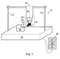
- the CMM 2 comprises a base 10, supporting a frame 12 which in turn holds a quill 14. Motors (not shown) are provided to move the quill 14 along the three mutually orthogonal axes X, Y and Z.
- the quill 14 holds an articulating head 16.
- the head 16 has a base portion 20 attached to the quill 14, an intermediate portion 22 and a probe retaining portion 24.
- the base portion 20 comprises a first motor (not shown) for rotating the intermediate portion 22 about a first rotational axis 18.
- the intermediate portion 22 comprises a second motor (not shown) for rotating the probe retaining portion 24 about a second rotational axis that is substantially perpendicular to the first rotational axis.
- bearings may also be provided between the moveable parts of the articulating head 16.
- measurement encoders may be provided for measuring the relative positions of the base 10, frame 12, quill 14, and articulating head 16 so that the position of the measurement probe 4 relative to a workpiece located on the base 10 can be determined.
- the probe 4 is removably mounted (e.g. using a kinematic mount) on the probe retaining portion 24.
- the probe 4 can be held by the probe retaining portion 24 by the use of corresponding magnets (not shown) provided on or in the probe 4 and probe retaining portion 24.
- the head 16 allows the probe 4 to be moved with two degrees of freedom relative to the quill 14.
- the combination of the two degrees of freedom provided by the head 16 and the three linear (X, Y, Z) axes of translation of the CMM 2 allows the probe 4 to be moved about five axes.
- the CMM controller 27 is arranged to provide appropriate drive currents to the first and second motors so that, during use, each motor imparts the required torque.
- the torque imparted by each motor may be used to cause movement about the associated rotational axis or to maintain a certain rotational position. It can thus be seen that a drive current needs to be applied continuously to each motor of the head 16 during use; i.e. each motor needs to be powered even if there is no movement required about the associated rotational axis.
- Figure 1 provides only a top level description of a CMM 2. A more complete description of such apparatus can be found elsewhere; for example, see EP402440 .
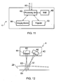
- the probe 4 comprises a projector 40 for projecting, under the control of a processing unit 42 a fringe pattern onto the object 28, an imaging device 44 for obtaining, under the control of the processing unit 42 an image of the object 28 onto which the fringe pattern is projected.
- the imaging device 44 comprises suitable optics and sensors for capturing images of the object 28.
- the imaging device comprises an image sensor, in particular a CCD defining an image plane 62.
- the imaging device 44 also comprises a lens (not shown) to focus light at the image plane 62.
- the processing unit 42 is connected to the probe controller 29 and image analyser 31 in the controller unit 26 such that the processing unit 42 can communicate with them via a communication line 46.
- the communication line 46 could be a wired or wireless communication line.
- the probe 4 also comprises a random access memory (RAM) device 48 for temporarily storing data, such as image data, used by the processing unit 42.
- RAM random access memory
- the probe 4 need not necessarily contain the processing unit 42 and/or RAM 48.
- all processing and data storage can be done by a device connected to the probe 4, for instance the controller 26 or an intermediate device connected between the probe 4 and controller 26.
- the projector's 40 image plane 60 and the imaging device's 44 image plane 62 are angled relative to each other such that the projector's 40 and imaging device's optical axes 61, 63 intersect at a reference plane 64.
- the probe 4 is positioned such that the fringes projected onto the object's surface can be clearly imaged by the imaging device 44.
- the projector 40 comprises a laser diode 50 for producing a coherent source of light, a collimator 52 for collimating light emitted from the laser diode 50, a grating 54 for producing a sinusoidal set of fringes, and a lens assembly 56 for focussing the fringes at the reference plane 64.
- the projector could comprise a light source and a mask to selectively block and transmit light emitted from the projector in a pattern.
- the periodic optical pattern projected by the projector 40 is a set of sinusoidal fringes.
- other forms of structured light could be projected, such as for example a set of parallel lines having different colours or tones (e.g. alternating black and white lines, or parallel red, blue and green lines), or even for example a set of concentric circles.
- the operation begins at step 100 when the operator turns the CMM 2 on.
- the system is initialised. This includes loading the probe 4 onto the articulating head 16, positioning the object 28 to be measured on the base 10, sending the CMM's encoders to a home or reference position such that the position of the articulating head 16 relative to the CMM 2 is known, and also calibrating the CMM 2 and probe 4 such that the position of a reference point of the probe 4 relative to the CMM 2 is known.
- This step is performed a plurality of times so that a plurality of image sets are obtained, wherein each set corresponds to a different perspective or view point of the object 28.
- three sets of images are obtained corresponding to three different perspectives. The process of obtaining a set of images is explained in more detail below with respect to Figure 5 .
- the images are analysed at step 106 by the image analyser 31 in the controller 26.
- the image analyser 31 calculates from the images a set of three dimensional ("3D") coordinates relative to the CMM 2 which describe the shape of the object 28.
- the method of analysing the images will be described in more detail below with reference to Figure 7 .
- the 3D coordinates are then output at step 108 as a 3D point cloud.
- the 3D point cloud could be stored on a memory device for later use.
- the 3D point cloud data could be used to determine the shape and dimensions of the object and compare it to predetermined threshold data to assess whether the object 28 has been made within predetermined tolerances.
- the 3D point cloud could be displayed on a graphical user interface which provides a user with virtual 3D model of the object 28.
- step 110 ends at step 110 when the system is turned off.
- a subsequent operation could be begun by repeating steps 104 to 108.
- the user might want to obtain multiple sets of measurement data for the same object 28, or to obtain measurement data for a different object.
- an initialising image is obtained at step 202. This involves the probe controller 29 sending a signal to the processing unit 42 of the probe 4 such that it operates the imaging device 44 to capture an image of the object 28.
- the initialising image is sent back to the image analyser 31 and at step 204, the image is analysed for image quality properties. This can include, for example, determining the average intensity of light and contrast of the image and comparing them to predetermined threshold levels to determine whether the image quality is sufficient to perform the measurement processes. For example, if the image is too dark then the imaging device 44 or projector 40 properties could be changed so as to increase the brightness of the projected fringe pattern and/or adjust the expose time or gain of the imaging device 44.
- the initialising image will not be used in subsequent processes for obtaining measurement data about the object 28 and so certain aspects of the image, such as the resolution of the image, need not be as high as that for the measurement images as discussed below.
- a light sensor such as a photodiode, separate to the imaging device could be provided in the probe to measure the amount of light at a perspective position, the output of the photodiode being used to set up the projector 40 and/or imaging device 44.
- the first measurement image is obtained at step 206.
- a measurement image is one which is used in the "analysis images" process 106 described in more detail below.
- Obtaining the first measurement image involves the probe controller 29 sending a signal to the processing unit 42 of the probe 4 such that the processing unit 42 then operates the projector 40 to project a fringe pattern onto the object 28 and for the imaging device 44 to simultaneously capture an image of the object 28 with the fringe pattern on it.
- the first measurement image is sent back to the image analyser 31 and at step 208, the first measurement image is again analysed for image quality properties. If the image quality is sufficient for use in the " analyses images" process 106 described below, then control is passed to step 210, otherwise control is passed back to step 204.
- fringe shifted images are obtained for the current perspective.
- Fringe shifted images are a plurality of images of the object from substantially the same perspective but with the position of the fringes being slightly different in each image. The method this step is described in more detail below with respect to Figure 6 .
- the capture perspective image set process 104 is repeated a plurality of times for a plurality of different perspectives.
- the capture perspective image set process is performed three times, for first, second and third perspectives.
- the probe 4 is moved to each perspective either under the control of the user or controller as explained above.
- the fringes projected on the object 28 are shifted by physically moving the probe 4 by a small distance in a direction such that the position of the fringes on the object 28 are different from the previous position.
- the projector 40 within it, and hence the projector's optical axis 61 will also be shifted relative to the object 28. This is what provides the change in position of the fringes of the object 28.
- the probe 4 is moved in a direction that is parallel to the imaging device's 44 image plane and perpendicular to the length of the fringes.
- the fringe shifting could be achieved by rotating the probe 4.
- the probe 4 could be rotated about an axis extending perpendicular to the projector's image plane 60.
- the probe could be rotated about an axis extending perpendicular to the imaging device's 44 image plane.
- the probe 4 can be rotated about the imaging device's 44 perspective centre. This is advantageous because this ensures that the perspective of the features captured by the imaging device 44 across the different images will be the same. It also enables any processing of the images to compensate for relative movement of the object and image sensor to be done without knowledge of the distance between the object and image sensor.
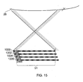
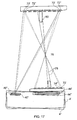
- the probe 4 is located at a first position (referred to by reference numeral 4') relative to an object 70 to be inspected.
- the probe's projector 40 is at a first position (referred to by reference numeral 40') which projects a fringe pattern illustrated by the dotted fringe markings 72' on the object 70.
- An image 74 of the object with the fringe markings 72' is captured by the imaging device 44 which is at a first position referred to by reference numeral 44'.
- the probe 4 is then moved to a second position, referred to by reference numeral 4", by rotating the probe 4 relative to the object 70 about the imaging device's perspective centre.
- an imaging device's perspective centre is the point through which all light rays that intersect with the image plane are assumed to pass.
- the perspective centre is referred to by reference numeral 76.
- the projector As can be seen, at the second position the projector, referred to by reference numeral 40", has moved such that the position of the fringe pattern on the object 70 has moved.
- the new position of the fringe pattern on the object 70 is illustrated by the striped fringe markings 72" on the object 70.
- An image 74 of the object is captured by the imaging device at its second position 44".
- the position of the image of the object on the imaging device 44 has changed between the first 44' and second 44" positions of the imaging device, the perspective the imaging device 44 has of the object 70 does not change between the positions. Accordingly, for example, features that are hidden due to occlusion in one image will also be hidden due to occlusion in the second.
- the rays 78 illustrating the view the imaging device 44 has of the tall feature 80 on the object.
- the imaging device 44 is rotated about its perspective centre, the rays 78 are identical for both positions and so only the location of the feature on the imaging device 44 changes between the positions, not the form of the feature itself.
- the probe 4 is moved a distance corresponding to a fringe shift of 1/4 period at the point where the imaging device's 44 optical axis 63 intersects the reference plane 64.
- the actual distance the probe 4 is moved will depend on the period of the fringes projected and other factors such as the magnification of the projector 40.
- step 302. Another measurement image is obtained at step 302.
- the steps of shifting the probe 300 and obtaining a measurement image 302 is repeated two more times. Each time, the probe is shifted so that for each measurement image the position of the fringe pattern on the object is different for all previous images. Accordingly, at the end of the obtain fringe shifted images process 210 four images of the object have been obtained for a given perspective, with the position of the fringe pattern on the object for each image being slightly different.
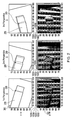
- Row A shows the view of the object 28 at each of the three perspectives with no fringes projected onto it.
- Row B illustrates, for each of the first, second and third perspectives the image 1000 that will be obtained by the imaging device 44 at step 206 of the process for capturing a perspective image set 104. Schematically shown behind each of those images 1000 are the fringe shifted images 1002, 1004 and 1006 which are obtained during execution of steps 300 and 302 for each of the first, second and third perspectives.
- Figures 14(a) to 14(d) shows an example of the images 1000 - 1006 obtained for the first perspective.
- the relative position of the object and imaging device has moved slightly between obtaining each image in an image set for a perspective, and this needs to be taken into consideration and/or compensated for during processing of the images as described in more detail below (especially as described in connection with Figure 8 ).
- the image analyser 31 will have a set of images 1000-1006 for each of the first, second and third perspectives.
- a wrapped phase map is a map which contains the phase of the fringes projected onto the object's surface for a plurality of pixels in one of the measurement images in a perspective image set, where the phase angle is bound within a range of 360 degrees.
- a wrapped phase map is obtained using each of the four phase shifted images for that perspective in a particular order.
- the four wrapped phase maps for a given perspective are obtained by using each of the four phase shifted images in different orders.
- the method for obtaining a wrapped phase map will be explained in more detail below with reference to Figure 8 .
- columns X, Y and Z illustrate for each of the different perspectives four different wrapped phase maps 1010, 1012, 1014 and 1016.
- Each of those wrapped phase maps for a given perspective has been calculated using a unique order of the four different images 1002 -1006 for that perspective.
- Four different wrapped phase maps 1010 - 1016 for each perspective are calculated in order to be able to distinguish between those discontinuities caused by features on the object 28 and those discontinuities caused by the wrapping of the phase, as explained in more detail below.
- a feature such as an edge or corner on the object 28 causes a discontinuity in the fringe pattern.
- edge 30 on the object 28 causes a discontinuity in the fringe pattern along line 32 in the image of the object 28 with the fringe projected on it. Accordingly, it is possible to identify features of the object 28 by identifying discontinuities in the fringe pattern.
- discontinuities in the fringe pattern are identified for each of the perspectives. This is achieved by identifying discontinuities in each of the wrapped phase maps.
- a discontinuity in a wrapped phase map is identified by comparing the phase value of each pixel to the phase values of adjacent surrounding pixels. If the difference in the phase value between adjacent pixels is above a threshold level, then one of those pixels identifies a discontinuity point. As will be understood, it is not important which one of those pixels is selected as the discontinuity point so long as the selection criteria is consistent for the selection of all discontinuity points, e.g. always select the pixel to the left or to the top of the difference, depending on whether the differences between adjacent pixels are being calculated in the x or y direction along the image.
- point 34 in the first wrapped phase map 1010 has been confirmed by discontinuities identified at the same point 34 in all the other wrapped phase maps 1012 to 1014, point 34 is identified as a real discontinuity, i.e. a discontinuity caused by a feature on the object 28, rather than as a result of phase wrapping.
- Calculating a wrapped phase map comprises calculating the phase for each pixel for one of a set of fringe-shifted images. This can be done using various techniques, the selection of which can depend on various factors including the method by which the fringe-shifted images are obtained. Standard phase-shifting algorithms rely on that the relative position between the object and imaging device 44 is the same across all of the fringe-shifted images. However, if either of the methods described above (e.g. either moving the probe 4 laterally or rotating it about the imaging device's perspective centre) are used to obtain the fringe-shifted images then the imaging device 44 will have moved a small distance relative to the object.
- Cropping the images is one example of a coordinate transformation, where the transformation is a linear function. This can be most accurate in situations where the distance to the object is known, or, for instance, where the stand-off distance is large compared to the depth of the measuring volume.
- the stand-off distance is the distance from the imaging device's perspective centre 76 to the centre of the imaging device's measurement volume and the depth of field 65 or depth of measurement volume is the range over which images recorded by the device appear sharp.
- the stand-off distance is the nominal distance from the probe 4 to the object to be measured. For instance, if the ratio of stand-off distance to depth of measuring volume is around 10:1 then there can be an error of up to 10% in the compensation for some pixels.
- the next step 502 involves using a phase-shifting algorithm to calculate the wrapped phase at each pixel.
- a suitable phase-shifting algorithm not requiring known phase shift for instance the Carré algorithm, may be used to calculate the wrapped phase, phase shift and modulation amplitude.
- the Carré algorithm is used to calculate for each pixel in a given image in an image set, the phase and phase shift and modulation amplitude from the four phase-shifted images.
- the Carré algorithm assumes that the four shifts in phase are equal. This will be the case, for instance, if the motion used is a translation and the surface is planar. If this is not the case then a good approximation can be obtained by choosing motion that it small enough that the surface gradient does not vary significantly over the scale of the motion.
- phase data can be converted to height data.
- phase shift data can be converted to gradient data and subsequently to height data using the method described below in connection with Figure 10 .
- a Carré algorithm provides both phase and phase shift data for each pixel in an image.
- the above methods described above in connection with Figure 9 use the phase data to obtain the height data. However, it has been possible to obtain the height information using the phase-shift data.
- a second process for obtaining the height map 410 will now be described with reference to Figure 10 .
- This method begins at step 700 by, for a continuous section (which is identifiable from the discontinuities previously identified as explained above), calculating a phase shift map using a Carré algorithm on all of the images in a perspective image set.
- the phase shift for a pixel is dependent on the gradient of the surface of the object and how far away the object is from the probe 4.
- step 702 to create a gradient map for the continuous section from that phase shift by directly mapping the phase shift value of each pixel to a gradient value using a predetermined mapping table and procedure.
- the gradient map is then integrated in order to get a height map for the continuous surface relative to the probe 4.
- the measured 3D coordinates of the real discontinuities obtained in step 408 are used in order to resolve the constant of integration to find the height above the reference plane 64.
- target points can be, quickly identified without a user having to place markers on the object or to configure a projector to selectively project target points onto the object. Furthermore, a high density of target points can be identified.
- the probe is mounted on a mounting structure equivalent to the quill of a CMM.
- This invention is also suitable for use with planning the course of motion of a measurement device mounted on other machine types.
- the probe 4 could be mounted on a machine tool.
- the probe 4 may be mounted onto the distal end of an inspection robot, which may for example comprise a robotic arm having several articulating joints.
- the probe 4 might be in a fixed position and the object could be moveable, for example via a positioning machine.
Claims (27)
- Un procédé sans contact pour l'inspection d'un objet (28) comprenant dans n'importe quel ordre approprié :i) l'obtention d'au moins une première image (1000) de l'objet sur laquelle une forme optique est projetée, prise à partir d'une première perspective ;(ii) l'obtention d'au moins une deuxième image (1000) de l'objet sur laquelle une forme optique est projetée, prise à partir d'une deuxième perspective qui est différente de la première perspective ; etiii) l'identification d'au moins une caractéristique commune de l'objet (34) dans chacune d'au moins une première et une deuxième images en se basant sur une irrégularité de la forme optique causée par la caractéristique de l'objet déformant la forme optique telle qu'elle est représentée dans au moins une première et une deuxième images, dans laquelle au moins l'une de la position relative et de l'orientation relative de l'objet (28) et du projecteur (40) de la forme optique à l'étape i) est différente de celle de l'objet et du projecteur de la forme optique à l'étape ii).
- Un procédé selon la revendication 1 dans lequel le projecteur (40) de la forme optique représentée à l'étape i) et le projecteur de la forme optique représentée à l'étape ii) sont fournis par une unité de projection de forme optique commune (4) comprenant au moins un projecteur, et dans lequel le procédé comprend par ailleurs le déplacement relatif de l'objet (28) et de l'unité de projection de forme optique entre les étapes i) et ii).
- Un procédé selon la revendication 2 comprenant le déplacement de l'unité de projection de forme optique (4) par rapport à l'objet (28).
- Un procédé selon la revendication 2 ou 3 dans lequel le projecteur (40) de la forme optique représentée à l'étape ii) est le projecteur de la forme optique représentée à l'étape i).
- Un procédé selon l'une quelconque des revendications précédentes dans lequel la forme optique projetée sur l'objet (28) à l'étape i) et à l'étape ii) est la même.
- Un procédé selon l'une quelconque des revendications précédentes dans lequel au moins une première image (1000) et au moins une deuxième image (1000) sont obtenues par une unité de dispositif d'imagerie (4) comprenant au moins un capteur d'image (44) et selon lequel le procédé comprend le déplacement du dispositif d'imagerie de la première perspective à la deuxième perspective.
- Un procédé selon la revendication 2 et la revendication 6, dans lequel l'unité de projection de formes optiques et l'unité de dispositif d'imagerie sont dans un rapport spatial fixe l'un par rapport à l'autre, et fournis en tant que sonde unique (4).
- Un procédé selon la revendication 7 dans lequel l'unité de projection de forme optique et l'unité de dispositif d'imagerie sont montés sur un appareil de positionnement à coordonnées (2).
- Un procédé selon l'une quelconque des revendications précédentes, comprenant par ailleurs l'utilisation d'au moins une première (1000) et une deuxième i mages pour mesurer la caractéristique commune dans lequel la mesure de la caractéristique commune comprend la détermination de la position de la caractéristique commune dans un volume de mesure.
- Un procédé selon l'une quelconque des revendications précédentes dans lequel :l'étape i) comprend l'obtention à partir d'une première perspective d'un ensemble de premières images de l'objet (28) etl'étape ii) comprend l'obtention à partir d'une deuxième perspective d'un ensemble de deuxièmes images de l'objet ;et dans lequel la position de la forme optique sur l'objet est différente pour chaque image appartenant à un ensemble.
- Un procédé selon la revendication 10 dans lequel l'étape iii) comprend :a) le calcul d'au moins une carte de première phase (1010) à partir de l'ensemble des premières images ;b) le calcul d'au moins une carte de deuxième phase à partir de l'ensemble des deuxièmes images ; etc) l'identification d'au moins une irrégularité commune (34) dans chacune d'au moins une carte de première phase et une carte de deuxième phase en tant que caractéristique commune de l'objet.
- Un procédé selon la revendication 11 dans lequel :l'étape a) comprend le calcul d'un ensemble de cartes de première phase (1010) à partir d'un ensemble de premières images, chaque carte de phase de l'ensemble faisant l'objet du calcul au moyen d'un ordre unique de l'ensemble des premières images ;l'étape b) comprend le calcul d'un ensemble de cartes de deuxième phase à partir d'un ensemble de deuxièmes images, chaque carte de phase de l'ensemble faisant l'objet du calcul au moyen d'un ordre unique de l'ensemble des deuxièmes images ; etl'étape c) comprend l'identification d'au moins une irrégularité commune (34) dans l'ensemble d'au moins une carte de première phase et un ensemble d'au moins une carte de deuxième phase en tant que caractéristique commune de l'objet.
- Un procédé selon la revendication 11 ou 12 dans lequel les cartes de phase (101) sont des cartes de phase enveloppées et dans lequel l'étape c) comprend la mise à l'écart des fausses irrégularités (36) causées par des données de phase enveloppées.
- Un procédé selon la revendication 13 dans lequel la mise à l'écart de fausses irrégularités (36) comprend la comparaison de chacune des cartes de phase enveloppées dans un ensemble et la mise à l'écart des points d'irrégularité non communément identifiés entre chacune des cartes de phase enveloppées.
- Un procédé selon l'une quelconque des revendications précédentes dans lequel l'identification d'au moins une irrégularité commune (34) comprend l'identification de caractéristiques correspondantes de l'objet entre les images des différentes perspectives.
- Un procédé selon l'une quelconque des revendications précédentes dans lequel le procédé comprend l'identification de chacune d'au moins la première image (1000) et d'au moins une deuxième image (1000) une pluralité d'irrégularités de la forme optique formée sur l'objet en tant que pluralité de caractéristiques communes de l'objet et la détermination de coordonnées tridimensionnelles de chacune des caractéristiques communes de l'objet sur l'objet dans un espace de mesure provenant d'au moins une première image et d'au moins une deuxième image.
- Un procédé selon la revendication 1 dans lequel une irrégularité est identifiée en identifiant dans une image les points de l'objet où le taux de changement de la forme optique est supérieur à un taux de changement seuil prédéterminé.
- Un appareil d'inspection d'un objet (28), cet appareil comprenant :au moins un projecteur (4) configuré pour effectuer la projection d'une forme optique à partir d'au moins la première et la deuxième perspectives sur un objet à mesurer ;au moins un dispositif d'imagerie (44) configuré pour obtenir à partir d'une première perspective de l'image au moins une première image de l'objet sur lequel une forme optique est projetée à partir de la première perspective de projecteur et configuré pour obtenir à partir d'une deuxième perspective de l'image au moins une deuxième image de l'objet sur lequel une forme optique est projetée à partir de la deuxième perspective du projecteur ; etun analyseur d'image (31) configuré pour identifier une irrégularité dans la forme optique causée par la caractéristique de l'objet déformant la forme optique dans chacune d'au moins une première et une deuxième images en tant que caractéristique commune de l'objet.
- Un appareil selon la revendication 18 dans lequel l'appareil comprend une unité de projection (4) comprenant au moins un projecteur, et dans lequel l'unité de projection et l'objet sont configurés de manière à être déplacés relativement entre la première et la deuxième perspectives du projecteur.
- Un appareil selon la revendication 18 ou 19 dans lequel l'appareil comprend une unité de dispositif d'imagerie (4) comprenant au moins un dispositif d'imagerie et dans lequel l'unité de dispositif d'imagerie et l'objet sont configurés de manière à être déplacés entre la première et la deuxième perspectives d'image.
- Un appareil selon la revendication 19 et la revendication 20, dans lequel l'unité de projection (4) et l'unité de dispositif d'imagerie (4) sont dans un rapport spatial fixe l'un par rapport à l'autre, et fournis en tant que sonde unique (4).
- Un appareil selon l'une quelconque des revendications 18 à 21 dans lequel l'unité de projection (4) et l'unité de dispositif d'imagerie (4) sont montés sur une pièce amovible d'une machine de positionnement à coordonnées (2).
- Un appareil selon la revendication 18 dans lequel l'analyseur d'image est confirmé pour identifier une irrégularité en identifiant dans une image les points de l'objet où le taux de changement de la forme optique est supérieur à un taux de de changement seuil prédéterminé.
- Un procédé mis en oeuvre par ordinateur comprenant :la réception de données d'une première image représentant au moins une première image d'un objet (28) sur lequel une forme optique est projetée à partir d'une première perspective de projecteur ; la première image étant prise à partir d'une première perspective d'image ;la réception de données d'une deuxième image représentant au moins une deuxième image de l'objet sur laquelle une forme optique est projetée à partir d'une deuxième perspective de projecteur qui est différente de la première perspective de projecteur, la deuxième image étant prise à partir d'une deuxième perspective d'image qui est différente de la première perspective d'image ; etl'analyse des données de la première et de la deuxième images afin d'identifier au moins une caractéristique commune de l'objet (34) sur la base d'une irrégularité de la forme optique causée par la caractéristique de l'objet déformant la forme optique en tant qu'image dans au moins une première et une deuxième images.
- Le code de programme informatique comprenant des instructions qui, lorsqu'elles sont exécutées par un périphérique de traitement de l'appareil selon l'une des revendications de 18 à 23, cause le périphérique de traitement d'exécuter le procédé de l'une des revendications de 1 à 17 et 24.
- Un support lisible par ordinateur portant le code de programme informatique tel que revendiqué dans la revendication 25
- Un contrôleur de machine comprenant :un processeur ; etun code de programme informatique pour stocker la mémoire selon la revendication 25
Priority Applications (1)
| Application Number | Priority Date | Filing Date | Title |
|---|---|---|---|
| EP15171807.9A EP2977719A1 (fr) | 2007-08-17 | 2008-08-15 | Appareil et methode de mesure sans contact |
Applications Claiming Priority (4)
| Application Number | Priority Date | Filing Date | Title |
|---|---|---|---|
| GBGB0716088.0A GB0716088D0 (en) | 2007-08-17 | 2007-08-17 | Non-contact measurement apparatus and method |
| GBGB0716109.4A GB0716109D0 (en) | 2007-08-17 | 2007-08-17 | Non-contact measurement apparatus and method |
| GBGB0716080.7A GB0716080D0 (en) | 2007-08-17 | 2007-08-17 | Non-contact measurement apparatus and method |
| PCT/GB2008/002758 WO2009024756A1 (fr) | 2007-08-17 | 2008-08-15 | Appareil et procédé de mesure sans contact |
Related Child Applications (1)
| Application Number | Title | Priority Date | Filing Date |
|---|---|---|---|
| EP15171807.9A Division EP2977719A1 (fr) | 2007-08-17 | 2008-08-15 | Appareil et methode de mesure sans contact |
Publications (2)
| Publication Number | Publication Date |
|---|---|
| EP2183544A1 EP2183544A1 (fr) | 2010-05-12 |
| EP2183544B1 true EP2183544B1 (fr) | 2015-07-15 |
Family
ID=39876207
Family Applications (4)
| Application Number | Title | Priority Date | Filing Date |
|---|---|---|---|
| EP15171807.9A Withdrawn EP2977719A1 (fr) | 2007-08-17 | 2008-08-15 | Appareil et methode de mesure sans contact |
| EP08788329.4A Not-in-force EP2183546B1 (fr) | 2007-08-17 | 2008-08-15 | Sonde sans contact |
| EP08788327.8A Not-in-force EP2183544B1 (fr) | 2007-08-17 | 2008-08-15 | Appareil et procédé de mesure sans contact |
| EP08788328.6A Active EP2183545B1 (fr) | 2007-08-17 | 2008-08-15 | Appareil et procédé de mesure d'analyse de phase |
Family Applications Before (2)
| Application Number | Title | Priority Date | Filing Date |
|---|---|---|---|
| EP15171807.9A Withdrawn EP2977719A1 (fr) | 2007-08-17 | 2008-08-15 | Appareil et methode de mesure sans contact |
| EP08788329.4A Not-in-force EP2183546B1 (fr) | 2007-08-17 | 2008-08-15 | Sonde sans contact |
Family Applications After (1)
| Application Number | Title | Priority Date | Filing Date |
|---|---|---|---|
| EP08788328.6A Active EP2183545B1 (fr) | 2007-08-17 | 2008-08-15 | Appareil et procédé de mesure d'analyse de phase |
Country Status (5)
| Country | Link |
|---|---|
| US (4) | US8923603B2 (fr) |
| EP (4) | EP2977719A1 (fr) |
| JP (4) | JP5943547B2 (fr) |
| CN (3) | CN101821579B (fr) |
| WO (3) | WO2009024758A1 (fr) |
Families Citing this family (128)
| Publication number | Priority date | Publication date | Assignee | Title |
|---|---|---|---|---|
| EP2142878B1 (fr) * | 2007-04-30 | 2018-09-26 | Renishaw PLC | Sonde analogique et procédé de fonctionnement |
| WO2008153127A1 (fr) * | 2007-06-15 | 2008-12-18 | Kabushiki Kaisha Toshiba | Instrument permettant d'examiner/de mesurer un objet qui doit être mesuré |
| WO2009024758A1 (fr) | 2007-08-17 | 2009-02-26 | Renishaw Plc | Sonde sans contact |
| DE102007054906B4 (de) | 2007-11-15 | 2011-07-28 | Sirona Dental Systems GmbH, 64625 | Verfahren zur optischen Vermessung der dreidimensionalen Geometrie von Objekten |
| GB0809037D0 (en) | 2008-05-19 | 2008-06-25 | Renishaw Plc | Video Probe |
| US9482755B2 (en) | 2008-11-17 | 2016-11-01 | Faro Technologies, Inc. | Measurement system having air temperature compensation between a target and a laser tracker |
| US7991575B2 (en) * | 2009-01-08 | 2011-08-02 | Trimble Navigation Limited | Method and system for measuring angles based on 360 degree images |
| CN102395898A (zh) * | 2009-02-17 | 2012-03-28 | 绝对机器人技术有限公司 | 对机器人臂的位置信息的测量 |
| DE102009015920B4 (de) | 2009-03-25 | 2014-11-20 | Faro Technologies, Inc. | Vorrichtung zum optischen Abtasten und Vermessen einer Umgebung |
| US9551575B2 (en) | 2009-03-25 | 2017-01-24 | Faro Technologies, Inc. | Laser scanner having a multi-color light source and real-time color receiver |
| JP4715944B2 (ja) * | 2009-04-03 | 2011-07-06 | オムロン株式会社 | 三次元形状計測装置、三次元形状計測方法、および三次元形状計測プログラム |
| GB0909635D0 (en) * | 2009-06-04 | 2009-07-22 | Renishaw Plc | Vision measurement probe |
| GB0915904D0 (en) | 2009-09-11 | 2009-10-14 | Renishaw Plc | Non-contact object inspection |
| US9113023B2 (en) | 2009-11-20 | 2015-08-18 | Faro Technologies, Inc. | Three-dimensional scanner with spectroscopic energy detector |
| US9529083B2 (en) | 2009-11-20 | 2016-12-27 | Faro Technologies, Inc. | Three-dimensional scanner with enhanced spectroscopic energy detector |
| DE102009057101A1 (de) | 2009-11-20 | 2011-05-26 | Faro Technologies, Inc., Lake Mary | Vorrichtung zum optischen Abtasten und Vermessen einer Umgebung |
| US9210288B2 (en) | 2009-11-20 | 2015-12-08 | Faro Technologies, Inc. | Three-dimensional scanner with dichroic beam splitters to capture a variety of signals |
| DE102009056177B4 (de) * | 2009-11-27 | 2014-07-10 | Siemens Aktiengesellschaft | Vorrichtung und Verfahren zur Messung und Kompensation von Bewegungseinflüssen bei Phasenschiebe-Profilometern und dessen Anwendung auf mobile, freihandgeführte Profilometrie |
| DE102009054591A1 (de) * | 2009-12-14 | 2011-06-16 | Robert Bosch Gmbh | Messwerkzeug zur Erfassung einer Kontur eines Gegenstands |
| WO2011090891A1 (fr) | 2010-01-20 | 2011-07-28 | Faro Technologies, Inc. | Affichage pour machine de mesure en coordonnées |
| US9879976B2 (en) | 2010-01-20 | 2018-01-30 | Faro Technologies, Inc. | Articulated arm coordinate measurement machine that uses a 2D camera to determine 3D coordinates of smoothly continuous edge features |
| US9607239B2 (en) | 2010-01-20 | 2017-03-28 | Faro Technologies, Inc. | Articulated arm coordinate measurement machine having a 2D camera and method of obtaining 3D representations |
| US20130222816A1 (en) * | 2010-01-20 | 2013-08-29 | Faro Technologies, Inc. | Coordinate measuring machine having an illuminated probe end and method of operation |
| US9628775B2 (en) | 2010-01-20 | 2017-04-18 | Faro Technologies, Inc. | Articulated arm coordinate measurement machine having a 2D camera and method of obtaining 3D representations |
| US9163922B2 (en) | 2010-01-20 | 2015-10-20 | Faro Technologies, Inc. | Coordinate measurement machine with distance meter and camera to determine dimensions within camera images |
| US8619265B2 (en) | 2011-03-14 | 2013-12-31 | Faro Technologies, Inc. | Automatic measurement of dimensional data with a laser tracker |
| US9377885B2 (en) | 2010-04-21 | 2016-06-28 | Faro Technologies, Inc. | Method and apparatus for locking onto a retroreflector with a laser tracker |
| US9400170B2 (en) | 2010-04-21 | 2016-07-26 | Faro Technologies, Inc. | Automatic measurement of dimensional data within an acceptance region by a laser tracker |
| US9772394B2 (en) | 2010-04-21 | 2017-09-26 | Faro Technologies, Inc. | Method and apparatus for following an operator and locking onto a retroreflector with a laser tracker |
| DE102010020925B4 (de) | 2010-05-10 | 2014-02-27 | Faro Technologies, Inc. | Verfahren zum optischen Abtasten und Vermessen einer Umgebung |
| JP5657276B2 (ja) * | 2010-05-14 | 2015-01-21 | 一般社団法人モアレ研究所 | 形状計測装置及び形状計測方法 |
| US10010268B2 (en) * | 2010-09-15 | 2018-07-03 | Olympus Corporation | Endoscope apparatus |
| DE102010038177B3 (de) * | 2010-10-14 | 2012-04-19 | Deutsches Zentrum für Luft- und Raumfahrt e.V. | Erfassen eines die Bilder von Punktemustern beeinflussenden Zustands eines Objekts |
| CN103180691B (zh) * | 2010-10-27 | 2016-08-10 | 株式会社尼康 | 形状测定装置、形状测定方法、构造物的制造方法 |
| US9168654B2 (en) | 2010-11-16 | 2015-10-27 | Faro Technologies, Inc. | Coordinate measuring machines with dual layer arm |
| US8755043B2 (en) * | 2010-11-19 | 2014-06-17 | Koh Young Technology Inc. | Method of inspecting a substrate |
| CN102713504B (zh) * | 2010-12-17 | 2014-08-27 | 松下电器产业株式会社 | 表面形状测定方法及表面形状测定装置 |
| US20120194651A1 (en) * | 2011-01-31 | 2012-08-02 | Nikon Corporation | Shape measuring apparatus |
| GB2518769A (en) | 2011-03-03 | 2015-04-01 | Faro Tech Inc | Target apparatus and method |
| EP2505959A1 (fr) | 2011-03-28 | 2012-10-03 | Renishaw plc | Contrôleur de machine de positionnement par coordonnées |
| US9164173B2 (en) | 2011-04-15 | 2015-10-20 | Faro Technologies, Inc. | Laser tracker that uses a fiber-optic coupler and an achromatic launch to align and collimate two wavelengths of light |
| US9482529B2 (en) | 2011-04-15 | 2016-11-01 | Faro Technologies, Inc. | Three-dimensional coordinate scanner and method of operation |
| US9686532B2 (en) | 2011-04-15 | 2017-06-20 | Faro Technologies, Inc. | System and method of acquiring three-dimensional coordinates using multiple coordinate measurement devices |
| US8537376B2 (en) | 2011-04-15 | 2013-09-17 | Faro Technologies, Inc. | Enhanced position detector in laser tracker |
| GB201107053D0 (en) | 2011-04-27 | 2011-06-08 | Univ Sheffield | Improvements in providing image data |
| US9280848B1 (en) * | 2011-10-24 | 2016-03-08 | Disney Enterprises Inc. | Rendering images with volumetric shadows using rectified height maps for independence in processing camera rays |
| JP5798823B2 (ja) * | 2011-07-22 | 2015-10-21 | 株式会社ミツトヨ | レーザ干渉測定装置の横座標校正治具および横座標校正方法 |
| WO2013019609A1 (fr) * | 2011-07-29 | 2013-02-07 | Hexagon Metrology, Inc. | Réduction des données d'un système de mesure de coordonnées |
| US9251562B1 (en) * | 2011-08-04 | 2016-02-02 | Amazon Technologies, Inc. | Registration of low contrast images |
| WO2013054814A1 (fr) | 2011-10-11 | 2013-04-18 | 株式会社ニコン | Dispositif et procédé de mesure de formes, système et procédé pour fabriquer des structures et programme de mesure de formes |
| CN102494625B (zh) * | 2011-11-22 | 2013-10-02 | 吴江市博众精工科技有限公司 | 一种镭射机构旋转模组 |
| CN102494624B (zh) * | 2011-11-22 | 2013-10-02 | 吴江市博众精工科技有限公司 | 一种镭射调整模组 |
| JP2013117453A (ja) * | 2011-12-05 | 2013-06-13 | Hitachi Ltd | 距離計測方法および装置とそれを搭載した形状計測装置 |
| GB201201140D0 (en) * | 2012-01-24 | 2012-03-07 | Phase Focus Ltd | Method and apparatus for determining object characteristics |
| DE102012100609A1 (de) | 2012-01-25 | 2013-07-25 | Faro Technologies, Inc. | Vorrichtung zum optischen Abtasten und Vermessen einer Umgebung |
| US20130226330A1 (en) * | 2012-02-24 | 2013-08-29 | Alliance For Sustainable Energy, Llc | Optical techniques for monitoring continuous manufacturing of proton exchange membrane fuel cell components |
| CN103376076A (zh) * | 2012-04-23 | 2013-10-30 | 鸿富锦精密工业(深圳)有限公司 | 三次元测针补偿及空间误差测定系统及方法 |
| GB201207800D0 (en) | 2012-05-03 | 2012-06-13 | Phase Focus Ltd | Improvements in providing image data |
| JP6132126B2 (ja) * | 2012-05-14 | 2017-05-24 | パルステック工業株式会社 | 透光性物体検査装置および透光性物体検査方法 |
| WO2013187203A1 (fr) * | 2012-06-12 | 2013-12-19 | 株式会社島精機製作所 | Appareil de mesure tridimensionnelle et procédé de mesure tridimensionnelle |
| US8997362B2 (en) | 2012-07-17 | 2015-04-07 | Faro Technologies, Inc. | Portable articulated arm coordinate measuring machine with optical communications bus |
| US10380469B2 (en) * | 2012-07-18 | 2019-08-13 | The Boeing Company | Method for tracking a device in a landmark-based reference system |
| US8823930B2 (en) | 2012-08-07 | 2014-09-02 | Carl Zeiss Industrielle Messtechnik Gmbh | Apparatus and method for inspecting an object |
| WO2014023345A1 (fr) * | 2012-08-07 | 2014-02-13 | Carl Zeiss Industrielle Messtechnik Gmbh | Dispositif amélioré pour inspecter un objet et procédé |
| JP5740370B2 (ja) * | 2012-09-04 | 2015-06-24 | 株式会社東芝 | 領域特定装置、方法、及びプログラム |
| CN103659465B (zh) * | 2012-09-21 | 2016-03-09 | 财团法人工业技术研究院 | 用于多轴机械的补偿控制方法 |
| US9513107B2 (en) | 2012-10-05 | 2016-12-06 | Faro Technologies, Inc. | Registration calculation between three-dimensional (3D) scans based on two-dimensional (2D) scan data from a 3D scanner |
| DE102012109481A1 (de) | 2012-10-05 | 2014-04-10 | Faro Technologies, Inc. | Vorrichtung zum optischen Abtasten und Vermessen einer Umgebung |
| US10067231B2 (en) | 2012-10-05 | 2018-09-04 | Faro Technologies, Inc. | Registration calculation of three-dimensional scanner data performed between scans based on measurements by two-dimensional scanner |
| GB201222361D0 (en) * | 2012-12-12 | 2013-01-23 | Univ Birmingham | Surface geometry imaging |
| BR112015023547B8 (pt) * | 2013-03-15 | 2022-09-27 | Synaptive Medical Inc | Montagem de braço automatizado para uso usado durante um procedimento médico sobre uma parte anatômica |
| US9041914B2 (en) | 2013-03-15 | 2015-05-26 | Faro Technologies, Inc. | Three-dimensional coordinate scanner and method of operation |
| KR101405227B1 (ko) * | 2013-04-02 | 2014-06-10 | 현대자동차 주식회사 | 컨베이어 라인의 속도측정장치 |
| US9736433B2 (en) * | 2013-05-17 | 2017-08-15 | The Boeing Company | Systems and methods for detection of clear air turbulence |
| US9651525B2 (en) * | 2013-06-27 | 2017-05-16 | TecScan Systems Inc. | Method and apparatus for scanning an object |
| US20150070468A1 (en) * | 2013-09-10 | 2015-03-12 | Faro Technologies, Inc. | Use of a three-dimensional imager's point cloud data to set the scale for photogrammetry |
| FI20135961A (fi) * | 2013-09-25 | 2015-03-26 | Aalto Korkeakoulusäätiö | Mallinnusjärjestely ja menetelmät ja järjestelmä kolmiulotteisen pinnan topografian mallintamiseksi |
| CN103528514B (zh) * | 2013-10-12 | 2016-09-21 | 南京理工大学 | 机器视觉多视场协同机构及装有该机构的测量与检测装置 |
| US9384540B2 (en) * | 2013-12-03 | 2016-07-05 | Sunedison Semiconductor Limited (Uen201334164H) | Systems and methods for interferometric phase measurement |
| WO2015134277A1 (fr) * | 2014-03-05 | 2015-09-11 | Faxitron Bioptics, Llc | Système et procédé pour imagerie multiaxiale de spécimens |
| EP2930462B1 (fr) * | 2014-04-08 | 2017-09-13 | Hexagon Technology Center GmbH | Procédé permettant de générer des informations concernant une chaîne de capteur d'une machine de mesure de coordonnées (CMM) |
| US9395174B2 (en) | 2014-06-27 | 2016-07-19 | Faro Technologies, Inc. | Determining retroreflector orientation by optimizing spatial fit |
| CA2955224C (fr) | 2014-08-08 | 2020-05-26 | Applied Research Associates, Inc. | Systemes, procedes et appareils de mesure de deformation de surface |
| CN104316012A (zh) * | 2014-11-25 | 2015-01-28 | 宁夏共享模具有限公司 | 一种用于大型零部件尺寸测量的工业机器人 |
| JP6388722B2 (ja) * | 2014-12-04 | 2018-09-12 | アプレ インストゥルメンツ, エルエルシーApre Instruments, Llc | 干渉非接触光プローブおよび測定 |
| CN107430719B (zh) | 2015-03-18 | 2021-01-22 | 美国联合包裹服务公司 | 用于验证货物内容的系统和方法 |
| CN107533690A (zh) | 2015-04-16 | 2018-01-02 | 美国联合包裹服务公司 | 增强型多层货物筛选系统、计算机程序产品及其使用方法 |
| CN104792263B (zh) * | 2015-04-20 | 2018-01-05 | 合肥京东方光电科技有限公司 | 确定显示母板的待检测区域的方法和装置 |
| WO2016183339A1 (fr) * | 2015-05-12 | 2016-11-17 | Hexagon Metrology, Inc. | Appareil et procédé de commande d'une machine de mesure de coordonnées à l'aide d'informations environnementales ou d'informations concernant une machine de mesure de coordonnées |
| JP7353757B2 (ja) * | 2015-07-13 | 2023-10-02 | レニショウ パブリック リミテッド カンパニー | アーチファクトを測定するための方法 |
| CN105157569B (zh) * | 2015-08-31 | 2018-05-22 | 宁夏共享模具有限公司 | 一种消失模模具激光测量机 |
| WO2017040977A1 (fr) | 2015-09-04 | 2017-03-09 | Faxitron Bioptics, Llc | Dispositif d'imagerie d'échantillons multi-axe avec marqueurs d'orientation incorporés |
| DE102015122844A1 (de) | 2015-12-27 | 2017-06-29 | Faro Technologies, Inc. | 3D-Messvorrichtung mit Batteriepack |
| JP6685767B2 (ja) * | 2016-02-25 | 2020-04-22 | 株式会社ミツトヨ | 表面性状測定機 |
| KR102084535B1 (ko) * | 2016-03-30 | 2020-03-05 | 가부시키가이샤 히다치 하이테크놀로지즈 | 결함 검사 장치, 결함 검사 방법 |
| ES2877499T3 (es) * | 2016-04-25 | 2021-11-17 | Alstom Transp Tech | Método de inspección de la integridad de un ensamble utilizando el rango activo |
| US10401145B2 (en) * | 2016-06-13 | 2019-09-03 | Carl Zeiss Industrielle Messtechnik Gmbh | Method for calibrating an optical arrangement |
| CN109477714B (zh) * | 2016-07-28 | 2022-02-18 | 瑞尼斯豪公司 | 非接触式测头和操作方法 |
| JP6295299B2 (ja) * | 2016-08-26 | 2018-03-14 | 株式会社ミツトヨ | 座標補正方法及び三次元測定装置 |
| CN107005703A (zh) * | 2016-09-09 | 2017-08-01 | 深圳市大疆创新科技有限公司 | 图像编码方法及系统 |
| US11083426B2 (en) | 2016-11-04 | 2021-08-10 | Hologic, Inc. | Specimen radiography system comprising cabinet and a specimen drawer positionable by a controller in the cabinet |
| JP2018110057A (ja) * | 2016-12-28 | 2018-07-12 | パナソニックIpマネジメント株式会社 | 照明システム、照明方法及びプログラム |
| JP6353573B1 (ja) * | 2017-03-02 | 2018-07-04 | Ckd株式会社 | 三次元計測装置 |
| JP6308637B1 (ja) * | 2017-05-08 | 2018-04-11 | 国立大学法人福井大学 | 特徴量を用いた3次元計測方法およびその装置 |
| EP3638875A4 (fr) | 2017-06-15 | 2021-03-24 | Drillscan France SAS | Génération de trajectoires de forage à l'aide d'un modèle de forage |
| CN107462164A (zh) * | 2017-08-17 | 2017-12-12 | 苏州新捷毅自动化科技有限公司 | 一种用投影仪做光源量测高度的方法 |
| US10969878B2 (en) | 2017-08-20 | 2021-04-06 | Pixart Imaging Inc. | Joystick with light emitter and optical sensor within internal chamber |
| US10372155B2 (en) * | 2017-08-20 | 2019-08-06 | Pixart Imaging Inc. | Joystick and related control method |
| EP3682228A4 (fr) | 2017-09-11 | 2021-06-16 | Faxitron Bioptics, LLC | Système d'imagerie à grossissement d'objet adaptatif |
| CN107664478B (zh) * | 2017-10-26 | 2023-11-03 | 成都众鑫聚合科技有限公司 | 一种立式非接触回转体高精度测量装置及其测量方法 |
| CN107990821B (zh) * | 2017-11-17 | 2019-12-17 | 深圳大学 | 一种桥梁形变监测方法、存储介质及桥梁形变监测接收机 |
| CN108441889B (zh) * | 2018-03-19 | 2020-06-26 | 河南科技大学 | 一种阳极导杆钢爪附着物检测方法及装置 |
| JP6888580B2 (ja) * | 2018-04-05 | 2021-06-16 | オムロン株式会社 | 情報処理装置、情報処理方法、及びプログラム |
| WO2019216336A1 (fr) * | 2018-05-09 | 2019-11-14 | 川崎重工業株式会社 | Procédé d'échantillonnage et système d'échantillonnage |
| GB2574064B (en) * | 2018-05-25 | 2020-05-27 | Imetrum Ltd | Motion encoder |
| CN111258157B (zh) * | 2018-11-30 | 2023-01-10 | 中强光电股份有限公司 | 投影机及亮度调整方法 |
| CN111258158B (zh) | 2018-11-30 | 2022-10-25 | 中强光电股份有限公司 | 投影机及亮度调整方法 |
| WO2020209855A1 (fr) * | 2019-04-11 | 2020-10-15 | Hewlett-Packard Development Company, L.P. | Imagerie tridimensionnelle |
| US11367201B2 (en) | 2019-09-24 | 2022-06-21 | The Boeing Company | System and method for continual localization of scanner using non-destructive inspection data |
| US10929670B1 (en) | 2019-10-21 | 2021-02-23 | The Boeing Company | Marker-to-model location pairing and registration for augmented reality applications |
| US20210291435A1 (en) * | 2020-03-19 | 2021-09-23 | Ricoh Company, Ltd. | Measuring apparatus, movable apparatus, robot, electronic device, fabricating apparatus, and measuring method |
| JP2021152525A (ja) * | 2020-03-19 | 2021-09-30 | 株式会社リコー | 計測装置、計測方法、移動体、ロボット、電子機器及び造形装置 |
| EP3910287A1 (fr) * | 2020-05-14 | 2021-11-17 | Fill Gesellschaft m.b.H. | Procédé et dispositif de mesure d'un objet physique |
| US11398085B2 (en) * | 2020-07-31 | 2022-07-26 | Wisconsin Alumni Research Foundation | Systems, methods, and media for directly recovering planar surfaces in a scene using structured light |
| CN112050749B (zh) * | 2020-08-18 | 2022-04-05 | 丰柯电子科技(上海)有限公司 | 一种汽车零部件加工用曲度在线检测装置及检测方法 |
| CN111951505B (zh) * | 2020-08-25 | 2022-02-08 | 青岛大学 | 基于分布式光纤系统的围栏振动入侵定位和模式识别方法 |
| US11717967B2 (en) | 2021-03-04 | 2023-08-08 | TecScan Systems Inc. | System and method for scanning an object using an array of ultrasonic transducers |
| CN115327541B (zh) * | 2022-10-12 | 2023-03-14 | 中国人民解放军国防科技大学 | 阵列扫描全息穿透成像方法及手持全息穿透成像雷达系统 |
Family Cites Families (120)
| Publication number | Priority date | Publication date | Assignee | Title |
|---|---|---|---|---|
| GB716109A (en) | 1950-06-22 | 1954-09-29 | Crosweller & Co Ltd W | Improvements in, or relating to, apparatus for winding paper, or other similar flexible strip material, into roll form |
| BE513714A (fr) | 1951-08-23 | 1900-01-01 | ||
| GB716088A (en) | 1952-10-29 | 1954-09-29 | Miguel Angel Mascarello | Improvements relating to musical instruments |
| US4468695A (en) | 1980-11-20 | 1984-08-28 | Tokico Ltd. | Robot |
| JPS6049475A (ja) * | 1983-08-29 | 1985-03-18 | Matsushita Electric Ind Co Ltd | 物体検出方法 |
| EP0178090B1 (fr) | 1984-09-19 | 1990-11-22 | Ishida Scales Mfg. Co. Ltd. | Procédé pour la détermination du volume |
| JPS61114109A (ja) | 1984-11-09 | 1986-05-31 | Ishida Scales Mfg Co Ltd | 重量判定方法 |
| JPH0623656B2 (ja) * | 1987-07-13 | 1994-03-30 | 新技術事業団 | 多眼視覚装置 |
| US5372502A (en) | 1988-09-02 | 1994-12-13 | Kaltenbach & Voight Gmbh & Co. | Optical probe and method for the three-dimensional surveying of teeth |
| DE3829925C2 (de) | 1988-09-02 | 1994-03-03 | Kaltenbach & Voigt | Vorrichtung zur optischen Vermessung von Zähnen in der Mundhöhle |
| GB8908854D0 (en) | 1989-04-19 | 1989-06-07 | Renishaw Plc | Method of and apparatus for scanning the surface of a workpiece |
| DE3938714A1 (de) | 1989-11-23 | 1991-05-29 | Bernd Dr Breuckmann | Verfahren zur optischen erfassung von formen von objekten |
| DE4007500A1 (de) | 1990-03-09 | 1991-09-12 | Zeiss Carl Fa | Verfahren und vorrichtung zur beruehrungslosen vermessung von objektoberflaechen |
| US5589942A (en) | 1990-04-05 | 1996-12-31 | Intelligent Automation Systems | Real time three dimensional sensing system |
| DE4121464A1 (de) | 1990-06-28 | 1992-01-09 | Mazda Motor | Vorrichtung zur feststellung von oberflaechendefekten |
| JP2926365B2 (ja) | 1990-11-30 | 1999-07-28 | マツダ株式会社 | 表面欠陥検査装置 |
| FR2664377A1 (fr) | 1990-07-03 | 1992-01-10 | Bertin & Cie | Appareil pour la determination de la forme tridimensionnelle d'un objet par voie optique sans contact. |
| US5251156A (en) | 1990-08-25 | 1993-10-05 | Carl-Zeiss-Stiftung, Heidenheim/Brenz | Method and apparatus for non-contact measurement of object surfaces |
| DE4134546A1 (de) * | 1991-09-26 | 1993-04-08 | Steinbichler Hans | Verfahren und vorrichtung zur bestimmung der absolut-koordinaten eines objektes |
| US5175601A (en) | 1991-10-15 | 1992-12-29 | Electro-Optical Information Systems | High-speed 3-D surface measurement surface inspection and reverse-CAD system |
| DE4301538A1 (de) | 1992-03-17 | 1994-07-28 | Peter Dr Ing Brueckner | Verfahren und Anordnung zur berührungslosen dreidimensionalen Messung, insbesondere zur Messung von Gebißmodellen |
| US5319445A (en) * | 1992-09-08 | 1994-06-07 | Fitts John M | Hidden change distribution grating and use in 3D moire measurement sensors and CMM applications |
| JPH06138055A (ja) | 1992-10-28 | 1994-05-20 | Sumitomo Metal Ind Ltd | 表面疵検査方法 |
| JP2996069B2 (ja) * | 1993-08-19 | 1999-12-27 | 村田機械株式会社 | 三次元計測装置 |
| US5488477A (en) * | 1993-11-15 | 1996-01-30 | Zygo Corporation | Methods and apparatus for profiling surfaces of transparent objects |
| JP3370418B2 (ja) | 1994-03-18 | 2003-01-27 | 株式会社資生堂 | 3次元形状測定システム |
| US6028672A (en) | 1996-09-30 | 2000-02-22 | Zheng J. Geng | High speed three dimensional imaging method |
| GB9515311D0 (en) | 1995-07-26 | 1995-09-20 | 3D Scanners Ltd | Stripe scanners and methods of scanning |
| DE19634254B4 (de) * | 1995-09-04 | 2009-06-10 | Volkswagen Ag | Optisch-numerisches Verfahren zur Ermittlung der gesamten Oberfläche eines dreidimensionalen Objektes |
| US5646733A (en) | 1996-01-29 | 1997-07-08 | Medar, Inc. | Scanning phase measuring method and system for an object at a vision station |
| US5953448A (en) * | 1996-03-01 | 1999-09-14 | Textile/Clothing Technology Corporation | Contour measurement of an object having a discontinuous surface using block point identification techniques |
| PT888522E (pt) | 1996-03-22 | 2001-10-30 | Univ Loughborough | Processo e aparelho para a medicao da forma de objectos |
| DE19618140A1 (de) | 1996-05-06 | 1997-11-13 | Fraunhofer Ges Forschung | 3D-Meßanordnung zur Ganzkörpererfassung und Einmessung einer entsprechenden Meßanordnung |
| IL127534A (en) | 1996-06-13 | 2001-08-26 | Leuven K U Res & Dev | Method and system for acquiring a three-dimensional shape description |
| JP3156602B2 (ja) * | 1996-10-11 | 2001-04-16 | 日産自動車株式会社 | 被検査面の欠陥検査方法 |
| US6600511B1 (en) | 1997-01-08 | 2003-07-29 | Pentax Corporation | Camera for use in photogrammetric analytical measurement |
| DE69833813T2 (de) | 1997-05-22 | 2006-11-30 | Kabushiki Kaisha Topcon | Vorrichtung zur Korrespondenzsuche in einem Bildpaar |
| US6438272B1 (en) | 1997-12-31 | 2002-08-20 | The Research Foundation Of State University Of Ny | Method and apparatus for three dimensional surface contouring using a digital video projection system |
| JP3922784B2 (ja) | 1998-01-27 | 2007-05-30 | 松下電工株式会社 | 3次元形状計測装置 |
| JPH11211442A (ja) | 1998-01-27 | 1999-08-06 | Matsushita Electric Works Ltd | 物体表面の欠陥検出方法及び装置 |
| US6291817B1 (en) * | 1998-06-23 | 2001-09-18 | Fuji Photo Optical Co., Ltd. | Moire apparatus having projection optical system and observation optical system which have optical axes parallel to each other |
| US6262803B1 (en) | 1998-09-10 | 2001-07-17 | Acuity Imaging, Llc | System and method for three-dimensional inspection using patterned light projection |
| JP2000097672A (ja) | 1998-09-18 | 2000-04-07 | Sanyo Electric Co Ltd | 3次元計測機における制御情報生成方法及び制御情報生成支援システム |
| DE19846145A1 (de) | 1998-10-01 | 2000-04-20 | Klaus Koerner | Verfahren und Anordung zur 3D-Aufnahme |
| HU220729B1 (hu) | 1998-10-06 | 2002-05-28 | EasyScan Műszaki Fejlesztő, Kereskedelmi és Szolgáltató Kft. | Eljárás és berendezés térbeli tárgy letapogatására és háromdimenziós számítógépes modell létrehozására |
| US6084712A (en) | 1998-11-03 | 2000-07-04 | Dynamic Measurement And Inspection,Llc | Three dimensional imaging using a refractive optic design |
| CA2253085A1 (fr) | 1998-11-06 | 2000-05-06 | Industrial Metrics Inc. | Methodes et systeme de mesure de coordonnees tridimensionnelles et d'etalonnage de la camera externe necessaire pour effectuer cette mesure |
| US6728423B1 (en) | 2000-04-28 | 2004-04-27 | Orametrix, Inc. | System and method for mapping a surface |
| US6738508B1 (en) | 2000-04-28 | 2004-05-18 | Orametrix, Inc. | Method and system for registering data |
| US6744932B1 (en) | 2000-04-28 | 2004-06-01 | Orametrix, Inc. | System and method for mapping a surface |
| US6532299B1 (en) * | 2000-04-28 | 2003-03-11 | Orametrix, Inc. | System and method for mapping a surface |
| US6744914B1 (en) | 2000-04-28 | 2004-06-01 | Orametrix, Inc. | Method and system for generating a three-dimensional object |
| US7068836B1 (en) * | 2000-04-28 | 2006-06-27 | Orametrix, Inc. | System and method for mapping a surface |
| US6771809B1 (en) | 2000-04-28 | 2004-08-03 | Orametrix, Inc. | Method and system for registering data |
| JP3417377B2 (ja) * | 1999-04-30 | 2003-06-16 | 日本電気株式会社 | 三次元形状計測方法及び装置並びに記録媒体 |
| US6100984A (en) | 1999-06-11 | 2000-08-08 | Chen; Fang | Surface measurement system with a laser light generator |
| JP3281918B2 (ja) | 1999-10-12 | 2002-05-13 | 和歌山大学長 | 形状計測方法および装置 |
| JP3714063B2 (ja) * | 1999-10-19 | 2005-11-09 | 富士ゼロックス株式会社 | 3次元形状計測装置 |
| DE10194788T1 (de) | 2000-01-07 | 2003-02-27 | Cyberoptics Corp | Phasenprofilometriesystem mit telezentrischem Projektor |
| JP4010753B2 (ja) | 2000-08-08 | 2007-11-21 | 株式会社リコー | 形状計測システムと撮像装置と形状計測方法及び記録媒体 |
| JP3554816B2 (ja) | 2000-09-14 | 2004-08-18 | 和歌山大学長 | 矩形波格子投影によるリアルタイム形状変形計測方法 |
| JP3687531B2 (ja) | 2000-11-27 | 2005-08-24 | 松下電工株式会社 | 3次元形状計測方法およびそのシステム |
| JP4390779B2 (ja) | 2001-02-14 | 2009-12-24 | 株式会社リコー | 画像入力装置 |
| JP4012710B2 (ja) | 2001-02-14 | 2007-11-21 | 株式会社リコー | 画像入力装置 |
| JP4123331B2 (ja) | 2001-03-16 | 2008-07-23 | 日本電気株式会社 | マルチメディア通信システムとマルチメディア通信可能な携帯無線通信端末及びメッセージ送受信方法 |
| US7061628B2 (en) | 2001-06-27 | 2006-06-13 | Southwest Research Institute | Non-contact apparatus and method for measuring surface profile |
| US7103211B1 (en) | 2001-09-04 | 2006-09-05 | Geometrix, Inc. | Method and apparatus for generating 3D face models from one camera |
| US20030123707A1 (en) | 2001-12-31 | 2003-07-03 | Park Seujeung P. | Imaging-based distance measurement and three-dimensional profiling system |
| TW550521B (en) * | 2002-02-07 | 2003-09-01 | Univ Nat Central | Method for re-building 3D model of house in a semi-automatic manner using edge segments of buildings |
| JP2003269928A (ja) | 2002-03-12 | 2003-09-25 | Nec Corp | 3次元形状計測方法および装置ならびにプログラム |
| DE10219054B4 (de) * | 2002-04-24 | 2004-08-26 | Fraunhofer-Gesellschaft zur Förderung der angewandten Forschung e.V. | Verfahren und Vorrichtung zur Bestimmung der räumlichen Koordinaten eines Gegenstandes |
| JP3921432B2 (ja) * | 2002-09-13 | 2007-05-30 | 株式会社リコー | モアレ光学系を用いた形状測定装置及び形状測定方法 |
| WO2004083778A1 (fr) | 2003-03-18 | 2004-09-30 | Hermary Alexander Thomas | Detecteur a balayage de profil a double observation et lumiere codee |
| JP4255865B2 (ja) | 2003-03-31 | 2009-04-15 | 株式会社ミツトヨ | 非接触三次元形状測定方法及び装置 |
| US7286246B2 (en) | 2003-03-31 | 2007-10-23 | Mitutoyo Corporation | Method and apparatus for non-contact three-dimensional surface measurement |
| WO2004096502A1 (fr) | 2003-04-28 | 2004-11-11 | Stephen James Crampton | Bras de machine de mesure de coordonnees a exosquelette |
| CA2435935A1 (fr) | 2003-07-24 | 2005-01-24 | Guylain Lemelin | Numeriseur tridimensionnel optique a zone de non-ambiguite elargie |
| ES2313036T3 (es) | 2003-07-24 | 2009-03-01 | Cognitens Ltd. | Procedimiento y sistema para la reconstruccion de la superficie tridimensional de un objeto. |
| US8050491B2 (en) * | 2003-12-17 | 2011-11-01 | United Technologies Corporation | CAD modeling system and method |
| DE10359104B3 (de) | 2003-12-17 | 2005-10-13 | Universität Karlsruhe | Verfahren zur dynamischen, dreidimensionalen Erfassung und Darstellung einer Oberfläche |
| WO2005073669A1 (fr) | 2004-01-29 | 2005-08-11 | Siemens Corporate Research, Inc. | Outil de calibrage d'appareil de prise de vue semi-automatique ou entierement automatique au moyen de dispositifs de mesure a laser |
| US7327857B2 (en) * | 2004-03-09 | 2008-02-05 | General Electric Company | Non-contact measurement method and apparatus |
| JP2005308553A (ja) * | 2004-04-21 | 2005-11-04 | Topcon Corp | 三次元画像計測装置及び方法 |
| JP4645068B2 (ja) * | 2004-06-04 | 2011-03-09 | 旭硝子株式会社 | 表面形状の検査方法および検査装置 |
| US7171328B1 (en) | 2004-08-30 | 2007-01-30 | Sandia Corporation | Method for measuring thermal properties using a long-wavelength infrared thermal image |
| JP4429135B2 (ja) * | 2004-10-05 | 2010-03-10 | Necエンジニアリング株式会社 | 三次元形状計測システム及び計測方法 |
| WO2006074310A2 (fr) | 2005-01-07 | 2006-07-13 | Gesturetek, Inc. | Creation d'images tridimensionnelles d'objets par illumination au moyen de motifs infrarouges |
| CA2656163C (fr) * | 2005-03-11 | 2011-07-19 | Creaform Inc. | Systeme autoreference et appareil de lecture optique 3d |
| WO2006107955A1 (fr) | 2005-04-06 | 2006-10-12 | Dimensional Photonics International, Inc. | Systeme de mesure de ligne hypsometrique d'interferometre a canaux multiples |
| US8044996B2 (en) * | 2005-05-11 | 2011-10-25 | Xenogen Corporation | Surface construction using combined photographic and structured light information |
| JP2007024764A (ja) * | 2005-07-20 | 2007-02-01 | Daihatsu Motor Co Ltd | 非接触三次元計測方法及びシステム |
| JP2007093412A (ja) | 2005-09-29 | 2007-04-12 | Fujinon Corp | 3次元形状測定装置 |
| US7538891B1 (en) | 2005-09-30 | 2009-05-26 | California Institute Of Technology | Surface characterization based on lateral shearing of diffracted wave fronts to measure in-plane and out-of-plane displacement gradient fields |
| JP2007114071A (ja) * | 2005-10-20 | 2007-05-10 | Omron Corp | 三次元形状計測装置、プログラム、コンピュータ読み取り可能な記録媒体、及び三次元形状計測方法 |
| US7898651B2 (en) | 2005-10-24 | 2011-03-01 | General Electric Company | Methods and apparatus for inspecting an object |
| JP4741344B2 (ja) * | 2005-11-07 | 2011-08-03 | ダイハツ工業株式会社 | 形状認識装置及び歪評価装置 |
| WO2007061632A2 (fr) * | 2005-11-09 | 2007-05-31 | Geometric Informatics, Inc. | Methode et appareil pour une imagerie de surface tridimensionnelle a coordonnees absolues |
| CA2528791A1 (fr) | 2005-12-01 | 2007-06-01 | Peirong Jia | Methode de mesure tridimensionnelle plein champ |
| GB2455926B (en) | 2006-01-30 | 2010-09-01 | Axellis Ltd | Method of preparing a medical restraint |
| US7773797B2 (en) | 2006-02-06 | 2010-08-10 | Beijing University Of Aeronautics And Astronautics | Methods and apparatus for measuring the flapping deformation of insect wings |
| KR100708352B1 (ko) | 2006-03-07 | 2007-04-18 | 한국과학기술원 | 모아레 원리의 2π 모호성과 위상천이 수단이 없도록실시되는 3차원 형상 측정장치 및 그 방법 |
| DE102006018558B4 (de) | 2006-04-21 | 2022-10-06 | QUISS Qualitäts-Inspektionssysteme und Service GmbH | Verfahren zum automatischen Aufbringen oder Erzeugen und Überwachen einer auf einem Substrat aufgebrachten Struktur mit Ermittlung von geometrischen Abmessungen |
| JP5028475B2 (ja) | 2006-04-27 | 2012-09-19 | スリーディー スキャナーズ リミテッド | 光学走査プローブ |
| JP2007315882A (ja) | 2006-05-25 | 2007-12-06 | Dainippon Printing Co Ltd | 基板位置決め装置、基板位置決め方法、カラーフィルタ製造装置、カラーフィルタ製造方法 |
| US20090268214A1 (en) * | 2006-05-26 | 2009-10-29 | Miljenko Lucic | Photogrammetric system and techniques for 3d acquisition |
| CN100520285C (zh) | 2006-07-13 | 2009-07-29 | 黑龙江科技学院 | 投射多频光栅的物体表面三维轮廓的视觉测量方法 |
| US8054471B2 (en) | 2006-09-15 | 2011-11-08 | Sciammarella Cesar A | System and method for analyzing displacements and contouring of surfaces |
| JP4905013B2 (ja) | 2006-09-19 | 2012-03-28 | 株式会社デンソー | 外観検査装置、外観検査方法及び高さ測定方法並びに回路基板製造方法 |
| US7256899B1 (en) | 2006-10-04 | 2007-08-14 | Ivan Faul | Wireless methods and systems for three-dimensional non-contact shape sensing |
| DE102006049695A1 (de) | 2006-10-16 | 2008-04-24 | Fraunhofer-Gesellschaft zur Förderung der angewandten Forschung e.V. | Vorrichtung und Verfahren zum berührungslosen Erfassen einer dreidimensionalen Kontur |
| KR100919166B1 (ko) | 2007-04-02 | 2009-09-28 | 한국과학기술원 | 스테레오 모아레를 이용한 3차원 형상 측정장치 및 그 방법 |
| US8111907B2 (en) * | 2007-07-31 | 2012-02-07 | United Technologies Corporation | Method for repeatable optical determination of object geometry dimensions and deviations |
| WO2009024758A1 (fr) | 2007-08-17 | 2009-02-26 | Renishaw Plc | Sonde sans contact |
| US8064068B2 (en) | 2008-01-25 | 2011-11-22 | Cyberoptics Corporation | Multi-source sensor for three-dimensional imaging using phased structured light |
| US8059280B2 (en) | 2008-01-31 | 2011-11-15 | Cyberoptics Corporation | Method for three-dimensional imaging using multi-phase structured light |
| US9170097B2 (en) | 2008-04-01 | 2015-10-27 | Perceptron, Inc. | Hybrid system |
| WO2010006081A1 (fr) | 2008-07-08 | 2010-01-14 | Chiaro Technologies, Inc. | Localisation de multiples canaux |
| CN102395898A (zh) * | 2009-02-17 | 2012-03-28 | 绝对机器人技术有限公司 | 对机器人臂的位置信息的测量 |
| US8045181B2 (en) | 2009-05-21 | 2011-10-25 | General Electric Company | Inspection system and method with multi-image phase shift analysis |
| US8582824B2 (en) | 2009-06-25 | 2013-11-12 | Twin Coast Metrology | Cell feature extraction and labeling thereof |
-
2008
- 2008-08-15 WO PCT/GB2008/002760 patent/WO2009024758A1/fr active Application Filing
- 2008-08-15 EP EP15171807.9A patent/EP2977719A1/fr not_active Withdrawn
- 2008-08-15 JP JP2010521465A patent/JP5943547B2/ja not_active Expired - Fee Related
- 2008-08-15 CN CN2008801112488A patent/CN101821579B/zh active Active
- 2008-08-15 EP EP08788329.4A patent/EP2183546B1/fr not_active Not-in-force
- 2008-08-15 CN CN200880112194.7A patent/CN101828092B/zh not_active Expired - Fee Related
- 2008-08-15 JP JP2010521466A patent/JP5485889B2/ja not_active Expired - Fee Related
- 2008-08-15 WO PCT/GB2008/002758 patent/WO2009024756A1/fr active Application Filing
- 2008-08-15 US US12/733,025 patent/US8923603B2/en active Active
- 2008-08-15 US US12/733,022 patent/US8792707B2/en active Active
- 2008-08-15 US US14/562,093 patent/USRE46012E1/en active Active
- 2008-08-15 EP EP08788327.8A patent/EP2183544B1/fr not_active Not-in-force
- 2008-08-15 CN CN200880111247.3A patent/CN101821578B/zh not_active Expired - Fee Related
- 2008-08-15 EP EP08788328.6A patent/EP2183545B1/fr active Active
- 2008-08-15 WO PCT/GB2008/002759 patent/WO2009024757A1/fr active Application Filing
- 2008-08-15 JP JP2010521467A patent/JP5689681B2/ja active Active
- 2008-08-15 US US12/733,021 patent/US8605983B2/en not_active Ceased
-
2014
- 2014-11-25 JP JP2014238225A patent/JP2015057612A/ja active Pending
Also Published As
| Publication number | Publication date |
|---|---|
| CN101821578B (zh) | 2014-03-12 |
| EP2183546A1 (fr) | 2010-05-12 |
| US20100142798A1 (en) | 2010-06-10 |
| JP2010537181A (ja) | 2010-12-02 |
| US20100158322A1 (en) | 2010-06-24 |
| CN101828092A (zh) | 2010-09-08 |
| JP5485889B2 (ja) | 2014-05-07 |
| JP5689681B2 (ja) | 2015-03-25 |
| EP2183546B1 (fr) | 2015-10-21 |
| EP2977719A1 (fr) | 2016-01-27 |
| US8923603B2 (en) | 2014-12-30 |
| EP2183544A1 (fr) | 2010-05-12 |
| CN101821579B (zh) | 2013-01-23 |
| CN101821578A (zh) | 2010-09-01 |
| WO2009024758A1 (fr) | 2009-02-26 |
| CN101828092B (zh) | 2014-03-12 |
| EP2183545A1 (fr) | 2010-05-12 |
| US8792707B2 (en) | 2014-07-29 |
| JP2015057612A (ja) | 2015-03-26 |
| WO2009024756A1 (fr) | 2009-02-26 |
| US8605983B2 (en) | 2013-12-10 |
| USRE46012E1 (en) | 2016-05-24 |
| WO2009024757A1 (fr) | 2009-02-26 |
| CN101821579A (zh) | 2010-09-01 |
| JP2010537183A (ja) | 2010-12-02 |
| JP5943547B2 (ja) | 2016-07-05 |
| JP2010537182A (ja) | 2010-12-02 |
| US20100135534A1 (en) | 2010-06-03 |
| EP2183545B1 (fr) | 2014-12-17 |
Similar Documents
| Publication | Publication Date | Title |
|---|---|---|
| EP2183544B1 (fr) | Appareil et procédé de mesure sans contact | |
| EP2475954B1 (fr) | Inspection des objets sans contact | |
| US8243286B2 (en) | Device and method for the contactless detection of a three-dimensional contour | |
| US10812694B2 (en) | Real-time inspection guidance of triangulation scanner | |
| EP0866308B1 (fr) | Capteur optique de profil | |
| US20150015701A1 (en) | Triangulation scanner having motorized elements | |
| CN105960569A (zh) | 使用二维图像处理来检查三维物体的方法 | |
| EP3989169A1 (fr) | Photogrammétrie hybride | |
| JP2006308452A (ja) | 3次元形状計測方法および装置 | |
| KR20040071531A (ko) | 3차원형상 측정장치 및 방법 | |
| Kujawińska | Hybrid methods of acquisition and analysis of 3D shape information |
Legal Events
| Date | Code | Title | Description |
|---|---|---|---|
| PUAI | Public reference made under article 153(3) epc to a published international application that has entered the european phase |
Free format text: ORIGINAL CODE: 0009012 |
|
| 17P | Request for examination filed |
Effective date: 20100310 |
|
| AK | Designated contracting states |
Kind code of ref document: A1 Designated state(s): AT BE BG CH CY CZ DE DK EE ES FI FR GB GR HR HU IE IS IT LI LT LU LV MC MT NL NO PL PT RO SE SI SK TR |
|
| AX | Request for extension of the european patent |
Extension state: AL BA MK RS |
|
| DAX | Request for extension of the european patent (deleted) | ||
| 17Q | First examination report despatched |
Effective date: 20120130 |
|
| REG | Reference to a national code |
Ref country code: DE Ref legal event code: R079 Ref document number: 602008039047 Country of ref document: DE Free format text: PREVIOUS MAIN CLASS: G01B0011000000 Ipc: G01B0011020000 |
|
| GRAP | Despatch of communication of intention to grant a patent |
Free format text: ORIGINAL CODE: EPIDOSNIGR1 |
|
| RIC1 | Information provided on ipc code assigned before grant |
Ipc: G01B 11/25 20060101ALI20140902BHEP Ipc: G06T 7/00 20060101ALI20140902BHEP Ipc: G01B 11/02 20060101AFI20140902BHEP |
|
| INTG | Intention to grant announced |
Effective date: 20140916 |
|
| GRAP | Despatch of communication of intention to grant a patent |
Free format text: ORIGINAL CODE: EPIDOSNIGR1 |
|
| INTG | Intention to grant announced |
Effective date: 20150205 |
|
| GRAS | Grant fee paid |
Free format text: ORIGINAL CODE: EPIDOSNIGR3 |
|
| GRAA | (expected) grant |
Free format text: ORIGINAL CODE: 0009210 |
|
| AK | Designated contracting states |
Kind code of ref document: B1 Designated state(s): AT BE BG CH CY CZ DE DK EE ES FI FR GB GR HR HU IE IS IT LI LT LU LV MC MT NL NO PL PT RO SE SI SK TR |
|
| REG | Reference to a national code |
Ref country code: CH Ref legal event code: EP Ref country code: GB Ref legal event code: FG4D |
|
| REG | Reference to a national code |
Ref country code: CH Ref legal event code: NV Representative=s name: KIRKER AND CIE S.A., CH |
|
| REG | Reference to a national code |
Ref country code: IE Ref legal event code: FG4D |
|
| REG | Reference to a national code |
Ref country code: AT Ref legal event code: REF Ref document number: 737032 Country of ref document: AT Kind code of ref document: T Effective date: 20150815 |
|
| REG | Reference to a national code |
Ref country code: DE Ref legal event code: R096 Ref document number: 602008039047 Country of ref document: DE |
|
| REG | Reference to a national code |
Ref country code: AT Ref legal event code: MK05 Ref document number: 737032 Country of ref document: AT Kind code of ref document: T Effective date: 20150715 |
|
| REG | Reference to a national code |
Ref country code: NL Ref legal event code: MP Effective date: 20150715 |
|
| REG | Reference to a national code |
Ref country code: LT Ref legal event code: MG4D |
|
| PG25 | Lapsed in a contracting state [announced via postgrant information from national office to epo] |
Ref country code: LT Free format text: LAPSE BECAUSE OF FAILURE TO SUBMIT A TRANSLATION OF THE DESCRIPTION OR TO PAY THE FEE WITHIN THE PRESCRIBED TIME-LIMIT Effective date: 20150715 Ref country code: NO Free format text: LAPSE BECAUSE OF FAILURE TO SUBMIT A TRANSLATION OF THE DESCRIPTION OR TO PAY THE FEE WITHIN THE PRESCRIBED TIME-LIMIT Effective date: 20151015 Ref country code: LV Free format text: LAPSE BECAUSE OF FAILURE TO SUBMIT A TRANSLATION OF THE DESCRIPTION OR TO PAY THE FEE WITHIN THE PRESCRIBED TIME-LIMIT Effective date: 20150715 Ref country code: FI Free format text: LAPSE BECAUSE OF FAILURE TO SUBMIT A TRANSLATION OF THE DESCRIPTION OR TO PAY THE FEE WITHIN THE PRESCRIBED TIME-LIMIT Effective date: 20150715 Ref country code: GR Free format text: LAPSE BECAUSE OF FAILURE TO SUBMIT A TRANSLATION OF THE DESCRIPTION OR TO PAY THE FEE WITHIN THE PRESCRIBED TIME-LIMIT Effective date: 20151016 |
|
| PG25 | Lapsed in a contracting state [announced via postgrant information from national office to epo] |
Ref country code: IS Free format text: LAPSE BECAUSE OF FAILURE TO SUBMIT A TRANSLATION OF THE DESCRIPTION OR TO PAY THE FEE WITHIN THE PRESCRIBED TIME-LIMIT Effective date: 20151115 Ref country code: PT Free format text: LAPSE BECAUSE OF FAILURE TO SUBMIT A TRANSLATION OF THE DESCRIPTION OR TO PAY THE FEE WITHIN THE PRESCRIBED TIME-LIMIT Effective date: 20151116 Ref country code: SE Free format text: LAPSE BECAUSE OF FAILURE TO SUBMIT A TRANSLATION OF THE DESCRIPTION OR TO PAY THE FEE WITHIN THE PRESCRIBED TIME-LIMIT Effective date: 20150715 Ref country code: PL Free format text: LAPSE BECAUSE OF FAILURE TO SUBMIT A TRANSLATION OF THE DESCRIPTION OR TO PAY THE FEE WITHIN THE PRESCRIBED TIME-LIMIT Effective date: 20150715 Ref country code: ES Free format text: LAPSE BECAUSE OF FAILURE TO SUBMIT A TRANSLATION OF THE DESCRIPTION OR TO PAY THE FEE WITHIN THE PRESCRIBED TIME-LIMIT Effective date: 20150715 Ref country code: HR Free format text: LAPSE BECAUSE OF FAILURE TO SUBMIT A TRANSLATION OF THE DESCRIPTION OR TO PAY THE FEE WITHIN THE PRESCRIBED TIME-LIMIT Effective date: 20150715 Ref country code: AT Free format text: LAPSE BECAUSE OF FAILURE TO SUBMIT A TRANSLATION OF THE DESCRIPTION OR TO PAY THE FEE WITHIN THE PRESCRIBED TIME-LIMIT Effective date: 20150715 |
|
| REG | Reference to a national code |
Ref country code: DE Ref legal event code: R097 Ref document number: 602008039047 Country of ref document: DE |
|
| PG25 | Lapsed in a contracting state [announced via postgrant information from national office to epo] |
Ref country code: MC Free format text: LAPSE BECAUSE OF FAILURE TO SUBMIT A TRANSLATION OF THE DESCRIPTION OR TO PAY THE FEE WITHIN THE PRESCRIBED TIME-LIMIT Effective date: 20150715 Ref country code: DK Free format text: LAPSE BECAUSE OF FAILURE TO SUBMIT A TRANSLATION OF THE DESCRIPTION OR TO PAY THE FEE WITHIN THE PRESCRIBED TIME-LIMIT Effective date: 20150715 Ref country code: SK Free format text: LAPSE BECAUSE OF FAILURE TO SUBMIT A TRANSLATION OF THE DESCRIPTION OR TO PAY THE FEE WITHIN THE PRESCRIBED TIME-LIMIT Effective date: 20150715 Ref country code: EE Free format text: LAPSE BECAUSE OF FAILURE TO SUBMIT A TRANSLATION OF THE DESCRIPTION OR TO PAY THE FEE WITHIN THE PRESCRIBED TIME-LIMIT Effective date: 20150715 Ref country code: CZ Free format text: LAPSE BECAUSE OF FAILURE TO SUBMIT A TRANSLATION OF THE DESCRIPTION OR TO PAY THE FEE WITHIN THE PRESCRIBED TIME-LIMIT Effective date: 20150715 |
|
| PLBE | No opposition filed within time limit |
Free format text: ORIGINAL CODE: 0009261 |
|
| STAA | Information on the status of an ep patent application or granted ep patent |
Free format text: STATUS: NO OPPOSITION FILED WITHIN TIME LIMIT |
|
| PG25 | Lapsed in a contracting state [announced via postgrant information from national office to epo] |
Ref country code: RO Free format text: LAPSE BECAUSE OF FAILURE TO SUBMIT A TRANSLATION OF THE DESCRIPTION OR TO PAY THE FEE WITHIN THE PRESCRIBED TIME-LIMIT Effective date: 20150715 |
|
| REG | Reference to a national code |
Ref country code: IE Ref legal event code: MM4A |
|
| REG | Reference to a national code |
Ref country code: FR Ref legal event code: ST Effective date: 20160429 |
|
| 26N | No opposition filed |
Effective date: 20160418 |
|
| PG25 | Lapsed in a contracting state [announced via postgrant information from national office to epo] |
Ref country code: IE Free format text: LAPSE BECAUSE OF NON-PAYMENT OF DUE FEES Effective date: 20150815 |
|
| PG25 | Lapsed in a contracting state [announced via postgrant information from national office to epo] |
Ref country code: SI Free format text: LAPSE BECAUSE OF FAILURE TO SUBMIT A TRANSLATION OF THE DESCRIPTION OR TO PAY THE FEE WITHIN THE PRESCRIBED TIME-LIMIT Effective date: 20150715 Ref country code: FR Free format text: LAPSE BECAUSE OF NON-PAYMENT OF DUE FEES Effective date: 20150915 |
|
| PG25 | Lapsed in a contracting state [announced via postgrant information from national office to epo] |
Ref country code: MT Free format text: LAPSE BECAUSE OF FAILURE TO SUBMIT A TRANSLATION OF THE DESCRIPTION OR TO PAY THE FEE WITHIN THE PRESCRIBED TIME-LIMIT Effective date: 20150715 |
|
| PG25 | Lapsed in a contracting state [announced via postgrant information from national office to epo] |
Ref country code: HU Free format text: LAPSE BECAUSE OF FAILURE TO SUBMIT A TRANSLATION OF THE DESCRIPTION OR TO PAY THE FEE WITHIN THE PRESCRIBED TIME-LIMIT; INVALID AB INITIO Effective date: 20080815 Ref country code: BG Free format text: LAPSE BECAUSE OF FAILURE TO SUBMIT A TRANSLATION OF THE DESCRIPTION OR TO PAY THE FEE WITHIN THE PRESCRIBED TIME-LIMIT Effective date: 20150715 |
|
| PG25 | Lapsed in a contracting state [announced via postgrant information from national office to epo] |
Ref country code: NL Free format text: LAPSE BECAUSE OF FAILURE TO SUBMIT A TRANSLATION OF THE DESCRIPTION OR TO PAY THE FEE WITHIN THE PRESCRIBED TIME-LIMIT Effective date: 20150715 Ref country code: CY Free format text: LAPSE BECAUSE OF FAILURE TO SUBMIT A TRANSLATION OF THE DESCRIPTION OR TO PAY THE FEE WITHIN THE PRESCRIBED TIME-LIMIT Effective date: 20150715 |
|
| PG25 | Lapsed in a contracting state [announced via postgrant information from national office to epo] |
Ref country code: BE Free format text: LAPSE BECAUSE OF NON-PAYMENT OF DUE FEES Effective date: 20150831 |
|
| PG25 | Lapsed in a contracting state [announced via postgrant information from national office to epo] |
Ref country code: TR Free format text: LAPSE BECAUSE OF FAILURE TO SUBMIT A TRANSLATION OF THE DESCRIPTION OR TO PAY THE FEE WITHIN THE PRESCRIBED TIME-LIMIT Effective date: 20150715 |
|
| PG25 | Lapsed in a contracting state [announced via postgrant information from national office to epo] |
Ref country code: LU Free format text: LAPSE BECAUSE OF NON-PAYMENT OF DUE FEES Effective date: 20150815 |
|
| PGFP | Annual fee paid to national office [announced via postgrant information from national office to epo] |
Ref country code: AT Payment date: 20180927 Year of fee payment: 11 |
|
| PGFP | Annual fee paid to national office [announced via postgrant information from national office to epo] |
Ref country code: IT Payment date: 20190822 Year of fee payment: 12 |
|
| PG25 | Lapsed in a contracting state [announced via postgrant information from national office to epo] |
Ref country code: LI Free format text: LAPSE BECAUSE OF NON-PAYMENT OF DUE FEES Effective date: 20190831 Ref country code: CH Free format text: LAPSE BECAUSE OF NON-PAYMENT OF DUE FEES Effective date: 20190831 |
|
| PGFP | Annual fee paid to national office [announced via postgrant information from national office to epo] |
Ref country code: GB Payment date: 20200825 Year of fee payment: 13 |
|
| PGFP | Annual fee paid to national office [announced via postgrant information from national office to epo] |
Ref country code: DE Payment date: 20201029 Year of fee payment: 13 |
|
| PG25 | Lapsed in a contracting state [announced via postgrant information from national office to epo] |
Ref country code: IT Free format text: LAPSE BECAUSE OF NON-PAYMENT OF DUE FEES Effective date: 20200815 |
|
| REG | Reference to a national code |
Ref country code: DE Ref legal event code: R119 Ref document number: 602008039047 Country of ref document: DE |
|
| GBPC | Gb: european patent ceased through non-payment of renewal fee |
Effective date: 20210815 |
|
| PG25 | Lapsed in a contracting state [announced via postgrant information from national office to epo] |
Ref country code: GB Free format text: LAPSE BECAUSE OF NON-PAYMENT OF DUE FEES Effective date: 20210815 Ref country code: DE Free format text: LAPSE BECAUSE OF NON-PAYMENT OF DUE FEES Effective date: 20220301 |