JP4645068B2 - 表面形状の検査方法および検査装置 - Google Patents
表面形状の検査方法および検査装置 Download PDFInfo
- Publication number
- JP4645068B2 JP4645068B2 JP2004167621A JP2004167621A JP4645068B2 JP 4645068 B2 JP4645068 B2 JP 4645068B2 JP 2004167621 A JP2004167621 A JP 2004167621A JP 2004167621 A JP2004167621 A JP 2004167621A JP 4645068 B2 JP4645068 B2 JP 4645068B2
- Authority
- JP
- Japan
- Prior art keywords
- transparent plate
- image
- surface shape
- stripe pattern
- reflected
- Prior art date
- Legal status (The legal status is an assumption and is not a legal conclusion. Google has not performed a legal analysis and makes no representation as to the accuracy of the status listed.)
- Active
Links
- 238000007689 inspection Methods 0.000 title claims description 52
- 238000000034 method Methods 0.000 title claims description 44
- 238000003384 imaging method Methods 0.000 claims description 28
- 239000011521 glass Substances 0.000 claims description 18
- 238000004364 calculation method Methods 0.000 claims description 14
- 239000000758 substrate Substances 0.000 claims description 6
- 239000000463 material Substances 0.000 claims 1
- 238000000926 separation method Methods 0.000 claims 1
- 238000010586 diagram Methods 0.000 description 20
- 230000003287 optical effect Effects 0.000 description 7
- 238000010191 image analysis Methods 0.000 description 6
- 230000003111 delayed effect Effects 0.000 description 5
- 230000010354 integration Effects 0.000 description 5
- 239000004973 liquid crystal related substance Substances 0.000 description 3
- 239000011347 resin Substances 0.000 description 3
- 229920005989 resin Polymers 0.000 description 3
- 230000001934 delay Effects 0.000 description 2
- 230000014509 gene expression Effects 0.000 description 2
- 238000004040 coloring Methods 0.000 description 1
- 238000005516 engineering process Methods 0.000 description 1
- 238000011156 evaluation Methods 0.000 description 1
- 239000000284 extract Substances 0.000 description 1
- 239000005357 flat glass Substances 0.000 description 1
- 238000007641 inkjet printing Methods 0.000 description 1
- 239000000203 mixture Substances 0.000 description 1
- 230000000737 periodic effect Effects 0.000 description 1
- 238000007639 printing Methods 0.000 description 1
- 230000003313 weakening effect Effects 0.000 description 1
Images


Classifications
-
- G—PHYSICS
- G01—MEASURING; TESTING
- G01B—MEASURING LENGTH, THICKNESS OR SIMILAR LINEAR DIMENSIONS; MEASURING ANGLES; MEASURING AREAS; MEASURING IRREGULARITIES OF SURFACES OR CONTOURS
- G01B11/00—Measuring arrangements characterised by the use of optical techniques
- G01B11/24—Measuring arrangements characterised by the use of optical techniques for measuring contours or curvatures
- G01B11/25—Measuring arrangements characterised by the use of optical techniques for measuring contours or curvatures by projecting a pattern, e.g. one or more lines, moiré fringes on the object
- G01B11/254—Projection of a pattern, viewing through a pattern, e.g. moiré
-
- G—PHYSICS
- G01—MEASURING; TESTING
- G01N—INVESTIGATING OR ANALYSING MATERIALS BY DETERMINING THEIR CHEMICAL OR PHYSICAL PROPERTIES
- G01N21/00—Investigating or analysing materials by the use of optical means, i.e. using sub-millimetre waves, infrared, visible or ultraviolet light
- G01N21/84—Systems specially adapted for particular applications
- G01N21/88—Investigating the presence of flaws or contamination
- G01N21/89—Investigating the presence of flaws or contamination in moving material, e.g. running paper or textiles
- G01N21/892—Investigating the presence of flaws or contamination in moving material, e.g. running paper or textiles characterised by the flaw, defect or object feature examined
- G01N21/896—Optical defects in or on transparent materials, e.g. distortion, surface flaws in conveyed flat sheet or rod
-
- G—PHYSICS
- G01—MEASURING; TESTING
- G01B—MEASURING LENGTH, THICKNESS OR SIMILAR LINEAR DIMENSIONS; MEASURING ANGLES; MEASURING AREAS; MEASURING IRREGULARITIES OF SURFACES OR CONTOURS
- G01B11/00—Measuring arrangements characterised by the use of optical techniques
- G01B11/24—Measuring arrangements characterised by the use of optical techniques for measuring contours or curvatures
- G01B11/25—Measuring arrangements characterised by the use of optical techniques for measuring contours or curvatures by projecting a pattern, e.g. one or more lines, moiré fringes on the object
-
- G—PHYSICS
- G01—MEASURING; TESTING
- G01B—MEASURING LENGTH, THICKNESS OR SIMILAR LINEAR DIMENSIONS; MEASURING ANGLES; MEASURING AREAS; MEASURING IRREGULARITIES OF SURFACES OR CONTOURS
- G01B11/00—Measuring arrangements characterised by the use of optical techniques
- G01B11/30—Measuring arrangements characterised by the use of optical techniques for measuring roughness or irregularity of surfaces
- G01B11/306—Measuring arrangements characterised by the use of optical techniques for measuring roughness or irregularity of surfaces for measuring evenness
-
- G—PHYSICS
- G01—MEASURING; TESTING
- G01N—INVESTIGATING OR ANALYSING MATERIALS BY DETERMINING THEIR CHEMICAL OR PHYSICAL PROPERTIES
- G01N21/00—Investigating or analysing materials by the use of optical means, i.e. using sub-millimetre waves, infrared, visible or ultraviolet light
- G01N21/84—Systems specially adapted for particular applications
- G01N21/88—Investigating the presence of flaws or contamination
- G01N21/8851—Scan or image signal processing specially adapted therefor, e.g. for scan signal adjustment, for detecting different kinds of defects, for compensating for structures, markings, edges
-
- G—PHYSICS
- G01—MEASURING; TESTING
- G01N—INVESTIGATING OR ANALYSING MATERIALS BY DETERMINING THEIR CHEMICAL OR PHYSICAL PROPERTIES
- G01N33/00—Investigating or analysing materials by specific methods not covered by groups G01N1/00 - G01N31/00
- G01N33/38—Concrete; ceramics; glass; bricks
- G01N33/386—Glass
-
- G—PHYSICS
- G06—COMPUTING; CALCULATING OR COUNTING
- G06T—IMAGE DATA PROCESSING OR GENERATION, IN GENERAL
- G06T7/00—Image analysis
- G06T7/0002—Inspection of images, e.g. flaw detection
- G06T7/0004—Industrial image inspection
- G06T7/0006—Industrial image inspection using a design-rule based approach
-
- G—PHYSICS
- G06—COMPUTING; CALCULATING OR COUNTING
- G06T—IMAGE DATA PROCESSING OR GENERATION, IN GENERAL
- G06T7/00—Image analysis
- G06T7/50—Depth or shape recovery
- G06T7/521—Depth or shape recovery from laser ranging, e.g. using interferometry; from the projection of structured light
-
- G—PHYSICS
- G01—MEASURING; TESTING
- G01N—INVESTIGATING OR ANALYSING MATERIALS BY DETERMINING THEIR CHEMICAL OR PHYSICAL PROPERTIES
- G01N21/00—Investigating or analysing materials by the use of optical means, i.e. using sub-millimetre waves, infrared, visible or ultraviolet light
- G01N21/84—Systems specially adapted for particular applications
- G01N21/88—Investigating the presence of flaws or contamination
- G01N21/8851—Scan or image signal processing specially adapted therefor, e.g. for scan signal adjustment, for detecting different kinds of defects, for compensating for structures, markings, edges
- G01N2021/8887—Scan or image signal processing specially adapted therefor, e.g. for scan signal adjustment, for detecting different kinds of defects, for compensating for structures, markings, edges based on image processing techniques
- G01N2021/8893—Scan or image signal processing specially adapted therefor, e.g. for scan signal adjustment, for detecting different kinds of defects, for compensating for structures, markings, edges based on image processing techniques providing a video image and a processed signal for helping visual decision
-
- G—PHYSICS
- G01—MEASURING; TESTING
- G01N—INVESTIGATING OR ANALYSING MATERIALS BY DETERMINING THEIR CHEMICAL OR PHYSICAL PROPERTIES
- G01N21/00—Investigating or analysing materials by the use of optical means, i.e. using sub-millimetre waves, infrared, visible or ultraviolet light
- G01N21/84—Systems specially adapted for particular applications
- G01N21/88—Investigating the presence of flaws or contamination
- G01N21/95—Investigating the presence of flaws or contamination characterised by the material or shape of the object to be examined
- G01N2021/9513—Liquid crystal panels
Description
本発明による他の態様の表面形状の検査方法は、ストライプパターンの暗部の幅と明暗の周期を調整することによって、透明板状体の表面による反射像と透明板状体の裏面による反射像とが撮像によって得られた画像信号では分離するように設定された明暗のパターンを有するストライプパターンを決定するストライプパターン決定工程と、撮像によって得られた画像信号から透明板状体の表面によるストライプパターンの反射像を選択し、選択した反射像を用いて透明板状体の表面形状を検査する表面形状検査工程とを含むことを特徴とする。
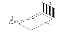
図1は、ガラス板などの透明板状体の表面の平坦度を検査するための検査装置の概要を示す模式図である。図1に示すように、検査装置は、載置台(図示せず)上に載せられた検査対象(被検査物体)であるガラス板などの透明板状体3の表面3aに映し出されたストライプパターン1を、撮像手段としてのCCDカメラ2によって撮像するように構成されている。ストライプパターン1は、光源(図示せず)の発光面に設けられている。図2は、ストライプパターン1の一例を示す説明図である。図2において、L1は暗部の幅を示し、L2は明部の幅を示す。L1+L2が明暗の周期に相当する。透明樹脂フィルムに黒色部分を着色してストライプパターン1を実現する場合には、明部は透明部分に相当し、暗部は黒色部分に相当する。
次に、第1ステップの実施例を説明する。表1の左欄に示すようなそれぞれの板厚の透明板状体3としてのガラス板について、表面反射像における暗部と裏面反射像における暗部とが重なり合わないようにすることができるストライプパターン1を実験により決定した。表1において、例えば、板厚0.35mmの透明板状体3では、明暗の周期(ピッチ)が、0.9mm、1.1mmまたは1.3mmのものが、板厚0.35mmの透明板状体3の表面形状の検査に適するストライプパターン1として使用できることを示す。それぞれの場合において、暗部の幅は、50μmまたは100μmである。

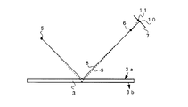
コンピュータ4は、CCDカメラ2から反射像26を入力し、2次元平面上の各々の反射像26の位置情報(具体的には、各々の低輝度部分の位置情報)を得る。また、理想的平面による各々の反射像19の位置情報(具体的には、各々の低輝度部分の位置情報)も認識できる。反射像26,19の受光面7における位置は、透明板状体3の表面における反射点31,32の位置に対応している。
Δ(x1)=(f’(x1)+f’(x2))×(x2−x1)/2
Δ(x2)=(f’(x2)+f’(x3))×(x3−x2)/2
・
・
Δ(x(n-1) )=(f’(x(n-1) )+f’(xn))×(xn−x(n-1) )/2
f(xn)=Δ(x1)+Δ(x2)+・・・+Δ(x(n-1) )
を算出することにより、各xにおけるうねりの高さを得る。
C=−(f(x1)+f(x2))×(x2−x1)/2
−(f(x2)+f(x3))×(x3−x2)/2
・
・
−(f(x(n-1) )+f(xn))×(xn−x(n-1) )/2
のように定めることにより、(4)式を満たす表面形状を得ることができる。
2 CCDカメラ
3 透明板状体
3a 表面
3b 裏面
4 コンピュータ
5 ストライプパターン上の点
7 受光面
19,26 反射像
31,32 反射点
Claims (10)
- ストライプパターンを透明板状体に照射し、該透明板状体の表面によって形成されるストライプパターンの反射像を撮像し、撮像によって得られた画像信号にもとづいて前記透明板状体の表面形状を検査する表面形状の検査方法であって、
ストライプパターンの暗部の幅と明暗の周期を調整することによって、前記透明板状体の表面による反射像と前記透明板状体の裏面による反射像とが前記撮像によって得られた画像信号では分離するように設定された明暗のパターンを有するストライプパターンを決定するストライプパターン決定工程と、
撮像によって得られた画像信号に含まれる反射像のうち、前記透明板状体の表面による前記ストライプパターンの反射像のみを用いて、前記透明板状体の表面形状を検査する表面形状検査工程とを含む
ことを特徴とする表面形状の検査方法。 - ストライプパターンを透明板状体に照射し、該透明板状体の表面によって形成されるストライプパターンの反射像を撮像し、撮像によって得られた画像信号にもとづいて前記透明板状体の表面形状を検査する表面形状の検査方法であって、
ストライプパターンの暗部の幅と明暗の周期を調整することによって、前記透明板状体の表面による反射像と前記透明板状体の裏面による反射像とが前記撮像によって得られた画像信号では分離するように設定された明暗のパターンを有するストライプパターンを決定するストライプパターン決定工程と、
撮像によって得られた画像信号から前記透明板状体の表面による前記ストライプパターンの反射像を選択し、選択した反射像を用いて前記透明板状体の表面形状を検査する表面形状検査工程とを含む
ことを特徴とする表面形状の検査方法。 - 表面形状検査工程で、定期的に現れる複数の低レベル部分を画像信号から見つけ、複数の低レベル部分のうち振幅が大きい方を反射像の信号とする
請求項1または2に記載の表面形状の検査方法。 - ストライプパターン決定工程で、前記透明板状体の表面による反射像の低レベル部分と前記透明板状体の裏面による反射像の低レベル部分との間の第1の間隔と、当該透明板状体の裏面による反射像の低レベル部分と画像信号において次に現れる前記透明板状体の表面による反射像の低レベル部分との間の第2の間隔とが異なるようなストライプパターンを決定し、
表面形状検査工程で、前記第1の間隔を形成する2つの低レベル部分のうちの一方を反射像の信号とする
請求項1または2に記載の表面形状の検査方法。 - 透明板状体として、フラットディスプレイパネルに用いられるガラス基板を検査する
請求項1、2、3または4に記載の表面形状の検査方法。 - 透明板状体として、自動車ガラスに用いられる素板を検査する
請求項1から5のいずれかに記載の表面形状の検査方法。 - 表面形状検査工程では、
透明板状体の表面が理想的平面である場合の理想反射像に対する反射像のずれ量を得て、
前記ずれ量、ストライプパターンの位置情報および撮像手段のレンズ中心位置情報を用いて前記透明板状体の表面形状の傾きを求め、
前記透明板状体の表面がほぼ平坦であることを拘束条件として、前記表面形状の傾きを積分して前記被測定物の表面形状を求める
請求項1から6のいずれかに記載の表面形状の検査方法。 - 透明板状体に照射されたストライプパターンの該透明板状体の表面によって形成される反射像を撮像する撮像手段を備え、前記撮像手段による撮像によって得られた画像信号にもとづいて前記透明板状体の表面形状を検査する表面形状の検査装置であって、
ストライプパターンの暗部の幅と明暗の周期を調整することによって、前記透明板状体の表面による反射像と前記透明板状体の裏面による反射像とが前記撮像手段によって得られた画像信号では分離するように設定された明暗のパターンを有するストライプパターンが設置され、
前記撮像手段によって得られた画像信号から前記透明板状体の表面による前記ストライプパターンの反射像を選択する選択手段と、
前記選択手段が選択した前記反射像を用いて、前記透明板状体の表面形状を検査する演算手段とを備えた
ことを特徴とする表面形状の検査装置。 - 演算手段は、透明板状体の表面が理想的平面である場合の理想反射像に対する反射像のずれ量を算出するずれ量算出手段と、前記ずれ量算出手段が算出したずれ量、ストライプパターンの位置情報および撮像手段のレンズ中心位置情報を用いて前記透明板状体の表面形状の傾きを算出する傾き算出手段と、前記被測定物の表面がほぼ平坦であることを拘束条件として、前記傾き算出手段が算出した表面形状の傾きを積分して前記透明板状体の表面形状を求める表面形状決定手段とを含む
請求項8に記載の表面形状の検査装置。 - 撮像手段はCCDカメラである請求項8または9に記載の表面形状の検査装置。
Priority Applications (7)
| Application Number | Priority Date | Filing Date | Title |
|---|---|---|---|
| JP2004167621A JP4645068B2 (ja) | 2004-06-04 | 2004-06-04 | 表面形状の検査方法および検査装置 |
| EP10014269A EP2278270A3 (en) | 2004-06-04 | 2005-06-02 | Optical method and apparatus for inspecting the front surface shape of plate shaped transparent objects |
| KR1020067017982A KR100828981B1 (ko) | 2004-06-04 | 2005-06-02 | 표면 형상의 검사 방법 및 검사 장치 |
| PCT/JP2005/010191 WO2005119172A1 (ja) | 2004-06-04 | 2005-06-02 | 表面形状の検査方法および検査装置 |
| EP05745755A EP1750087B1 (en) | 2004-06-04 | 2005-06-02 | Method and apparatus for inspecting a front surface shape |
| TW094118386A TW200606399A (en) | 2004-06-04 | 2005-06-03 | Inspection method, and inspection device for surface shape |
| US11/561,517 US7394536B2 (en) | 2004-06-04 | 2006-11-20 | Method and apparatus for inspecting front surface shape |
Applications Claiming Priority (1)
| Application Number | Priority Date | Filing Date | Title |
|---|---|---|---|
| JP2004167621A JP4645068B2 (ja) | 2004-06-04 | 2004-06-04 | 表面形状の検査方法および検査装置 |
Publications (3)
| Publication Number | Publication Date |
|---|---|
| JP2005345383A JP2005345383A (ja) | 2005-12-15 |
| JP2005345383A5 JP2005345383A5 (ja) | 2007-02-15 |
| JP4645068B2 true JP4645068B2 (ja) | 2011-03-09 |
Family
ID=35463002
Family Applications (1)
| Application Number | Title | Priority Date | Filing Date |
|---|---|---|---|
| JP2004167621A Active JP4645068B2 (ja) | 2004-06-04 | 2004-06-04 | 表面形状の検査方法および検査装置 |
Country Status (6)
| Country | Link |
|---|---|
| US (1) | US7394536B2 (ja) |
| EP (2) | EP1750087B1 (ja) |
| JP (1) | JP4645068B2 (ja) |
| KR (1) | KR100828981B1 (ja) |
| TW (1) | TW200606399A (ja) |
| WO (1) | WO2005119172A1 (ja) |
Families Citing this family (33)
| Publication number | Priority date | Publication date | Assignee | Title |
|---|---|---|---|---|
| KR101242984B1 (ko) | 2005-07-15 | 2013-03-12 | 아사히 가라스 가부시키가이샤 | 형상 검사 방법 및 장치 |
| US7589844B2 (en) * | 2005-07-15 | 2009-09-15 | Asahi Glass Company, Limited | Shape inspection method and apparatus |
| JP4907201B2 (ja) * | 2006-03-20 | 2012-03-28 | 株式会社神戸製鋼所 | 形状測定装置 |
| DE102006015792A1 (de) | 2006-04-05 | 2007-10-18 | Isra Surface Vision Gmbh | Verfahren und System zur Formmessung einer reflektierenden Oberfläche |
| EP1882896B1 (de) * | 2006-07-24 | 2014-12-17 | 3D-Shape GmbH | Dreidimensionale Vermessung der Form und der lokalen Oberflächennormalen von spiegelnden Objekten |
| US7471383B2 (en) * | 2006-12-19 | 2008-12-30 | Pilkington North America, Inc. | Method of automated quantitative analysis of distortion in shaped vehicle glass by reflected optical imaging |
| US8284392B2 (en) | 2007-03-13 | 2012-10-09 | 3D-Shape Gmbh | Method and apparatus for the three-dimensional measurement of the shape and the local surface normal of preferably specular objects |
| EP2183546B1 (en) | 2007-08-17 | 2015-10-21 | Renishaw PLC | Non-contact probe |
| US7843557B2 (en) * | 2007-09-28 | 2010-11-30 | Cardinal Scientific, Inc. | Method and system for detecting retroreflectors |
| JP5034891B2 (ja) * | 2007-11-21 | 2012-09-26 | 旭硝子株式会社 | 透明板状体の形状測定装置及び板ガラスの製造方法 |
| DE112009000272T5 (de) * | 2008-07-30 | 2011-06-09 | Aisin AW Co., Ltd., Anjo-shi | Antriebseinheit und Fahrzeug |
| US8441532B2 (en) * | 2009-02-24 | 2013-05-14 | Corning Incorporated | Shape measurement of specular reflective surface |
| GB0915904D0 (en) | 2009-09-11 | 2009-10-14 | Renishaw Plc | Non-contact object inspection |
| FR2951544A1 (fr) * | 2009-10-21 | 2011-04-22 | Saint Gobain | Procede d'analyse de la qualite d'un vitrage |
| JP5817721B2 (ja) * | 2010-06-07 | 2015-11-18 | 旭硝子株式会社 | 形状測定装置、形状測定方法、およびガラス板の製造方法 |
| KR20130090326A (ko) * | 2010-06-15 | 2013-08-13 | 아사히 가라스 가부시키가이샤 | 형상 측정 장치, 형상 측정 방법 및 유리판의 제조 방법 |
| KR101249758B1 (ko) * | 2010-11-25 | 2013-04-02 | (주)쎄미시스코 | 유리 기판의 불균일도 측정 시스템 및 방법 |
| US8351051B2 (en) | 2010-11-25 | 2013-01-08 | Semisysco Co., Ltd. | System and method of measuring irregularity of a glass substrate |
| US20120133761A1 (en) * | 2010-11-30 | 2012-05-31 | Angstrom, Inc. | Uneven area inspection system |
| JP5529829B2 (ja) * | 2011-11-01 | 2014-06-25 | 株式会社神戸製鋼所 | 高さ測定装置及び高さ測定方法 |
| US9349182B2 (en) * | 2011-11-10 | 2016-05-24 | Carestream Health, Inc. | 3D intraoral measurements using optical multiline method |
| US9295532B2 (en) * | 2011-11-10 | 2016-03-29 | Carestream Health, Inc. | 3D intraoral measurements using optical multiline method |
| JP5749150B2 (ja) * | 2011-12-22 | 2015-07-15 | 株式会社Sumco | シリカガラスルツボの赤外吸収スペクトルの三次元分布の決定方法、シリコン単結晶の製造方法 |
| EP2860490A4 (en) * | 2012-06-12 | 2016-03-02 | Shima Seiki Mfg | THREE-DIMENSIONAL MEASURING APPARATUS AND THREE-DIMENSIONAL MEASURING METHOD |
| WO2015098887A1 (ja) * | 2013-12-27 | 2015-07-02 | 旭硝子株式会社 | 形状測定装置、形状測定方法、およびガラス板の製造方法 |
| CN103995000B (zh) * | 2014-05-15 | 2017-01-11 | 京东方科技集团股份有限公司 | 一种显示基板的检查装置及检查系统 |
| WO2016032470A1 (en) | 2014-08-28 | 2016-03-03 | Carestream Health, Inc. | 3- d intraoral measurements using optical multiline method |
| JP5923644B2 (ja) * | 2015-05-13 | 2016-05-24 | 株式会社Sumco | シリカガラスルツボの赤外吸収スペクトルの三次元分布の決定方法、シリコン単結晶の製造方法 |
| CN105091784A (zh) * | 2015-06-30 | 2015-11-25 | 东莞市盟拓光电科技有限公司 | 用于表面为镜面或透明表面的被测物的三维成像系统 |
| JP6642223B2 (ja) | 2016-04-13 | 2020-02-05 | Agc株式会社 | 透明板表面検査装置、透明板表面検査方法、およびガラス板の製造方法 |
| DE102016223671A1 (de) * | 2016-11-29 | 2018-05-30 | Continental Automotive Gmbh | Leuchtsystem zur Ermittlung geometrischer Eigenschaften sowie Fahrerassistenzsystem und Verfahren dazu |
| KR102199314B1 (ko) * | 2019-03-07 | 2021-01-06 | (주) 인텍플러스 | 디스플레이 패널 검사장치 |
| JP7083856B2 (ja) * | 2020-01-07 | 2022-06-13 | 日本電子株式会社 | 高さ測定装置、荷電粒子線装置、および高さ測定方法 |
Citations (2)
| Publication number | Priority date | Publication date | Assignee | Title |
|---|---|---|---|---|
| JP2001502800A (ja) * | 1996-10-18 | 2001-02-27 | インノメス・ゲゼルシャフト・フュア・メステクニク・エム・ベー・ハー | 反射表面の経路を測定する方法及び装置 |
| JP2004514882A (ja) * | 2000-11-22 | 2004-05-20 | サン−ゴバン グラス フランス | 基板表面の走査方法および装置 |
Family Cites Families (3)
| Publication number | Priority date | Publication date | Assignee | Title |
|---|---|---|---|---|
| US5475452A (en) * | 1994-02-24 | 1995-12-12 | Keravision, Inc. | Device and method for mapping objects |
| JP3411829B2 (ja) | 1997-07-02 | 2003-06-03 | 旭硝子株式会社 | 表面形状の評価方法および評価装置 |
| JP2004167621A (ja) | 2002-11-19 | 2004-06-17 | Toyo Advanced Technologies Co Ltd | ホーニング加工装置の砥石径拡縮部材の作動方法およびホーニング加工装置 |
-
2004
- 2004-06-04 JP JP2004167621A patent/JP4645068B2/ja active Active
-
2005
- 2005-06-02 WO PCT/JP2005/010191 patent/WO2005119172A1/ja not_active Application Discontinuation
- 2005-06-02 EP EP05745755A patent/EP1750087B1/en not_active Expired - Fee Related
- 2005-06-02 KR KR1020067017982A patent/KR100828981B1/ko active IP Right Grant
- 2005-06-02 EP EP10014269A patent/EP2278270A3/en not_active Withdrawn
- 2005-06-03 TW TW094118386A patent/TW200606399A/zh unknown
-
2006
- 2006-11-20 US US11/561,517 patent/US7394536B2/en active Active
Patent Citations (2)
| Publication number | Priority date | Publication date | Assignee | Title |
|---|---|---|---|---|
| JP2001502800A (ja) * | 1996-10-18 | 2001-02-27 | インノメス・ゲゼルシャフト・フュア・メステクニク・エム・ベー・ハー | 反射表面の経路を測定する方法及び装置 |
| JP2004514882A (ja) * | 2000-11-22 | 2004-05-20 | サン−ゴバン グラス フランス | 基板表面の走査方法および装置 |
Also Published As
| Publication number | Publication date |
|---|---|
| US20070091319A1 (en) | 2007-04-26 |
| US7394536B2 (en) | 2008-07-01 |
| TWI372235B (ja) | 2012-09-11 |
| WO2005119172A1 (ja) | 2005-12-15 |
| KR100828981B1 (ko) | 2008-05-14 |
| EP2278270A3 (en) | 2011-10-19 |
| JP2005345383A (ja) | 2005-12-15 |
| EP2278270A2 (en) | 2011-01-26 |
| EP1750087A1 (en) | 2007-02-07 |
| EP1750087B1 (en) | 2011-12-21 |
| TW200606399A (en) | 2006-02-16 |
| KR20070019984A (ko) | 2007-02-16 |
| EP1750087A4 (en) | 2008-03-26 |
Similar Documents
| Publication | Publication Date | Title |
|---|---|---|
| JP4645068B2 (ja) | 表面形状の検査方法および検査装置 | |
| EP2102587B1 (en) | Method of automated quantitative analysis of distortion shaped vehicle glass by reflected optical imaging | |
| JP4793266B2 (ja) | 透明板状体の欠陥検査方法および装置 | |
| US8284396B2 (en) | System and device for the optical inspection of glass panels | |
| JP4730836B2 (ja) | 面歪の測定装置及び方法 | |
| US9030554B2 (en) | Device for analysing the surface of a substrate | |
| JP2012021781A (ja) | 表面形状の評価方法および評価装置 | |
| JP3411829B2 (ja) | 表面形状の評価方法および評価装置 | |
| JP4613626B2 (ja) | 鏡面形状測定方法および装置並びに検査方法および装置 | |
| US6376829B1 (en) | Method of and apparatus for inspecting surface irregularities of transparent plate | |
| KR20120065948A (ko) | 표면 형상의 평가 방법 및 표면 형상의 평가 장치 | |
| CN102445168A (zh) | 表面形状的检查方法及检查装置 | |
| JP5034891B2 (ja) | 透明板状体の形状測定装置及び板ガラスの製造方法 | |
| JPH11271038A (ja) | 塗装欠陥検査装置 | |
| JP2005181070A (ja) | 透明板状体の欠点検出方法及び欠点検出装置 | |
| JP4842376B2 (ja) | 表面検査装置及び方法 | |
| JP4679282B2 (ja) | 基板検査装置及び基板検査方法 | |
| JPH0629705B2 (ja) | 板状体の歪検査方法 | |
| TWI692614B (zh) | 膜厚測定裝置、基板檢查裝置、膜厚測定方法及基板檢查方法 | |
| JP2009128476A (ja) | インクヘッド吐出検査方法及び吐出検査装置 | |
| JP4657700B2 (ja) | 測定装置の校正方法 | |
| CN116601669A (zh) | 用于测量透明的玻璃板的影响的方法 | |
| JP2014016326A (ja) | 基板検査方法及び装置 |
Legal Events
| Date | Code | Title | Description |
|---|---|---|---|
| A521 | Request for written amendment filed |
Free format text: JAPANESE INTERMEDIATE CODE: A523 Effective date: 20061225 |
|
| A621 | Written request for application examination |
Free format text: JAPANESE INTERMEDIATE CODE: A621 Effective date: 20070425 |
|
| A131 | Notification of reasons for refusal |
Free format text: JAPANESE INTERMEDIATE CODE: A131 Effective date: 20100706 |
|
| A521 | Request for written amendment filed |
Free format text: JAPANESE INTERMEDIATE CODE: A523 Effective date: 20100903 |
|
| TRDD | Decision of grant or rejection written | ||
| A01 | Written decision to grant a patent or to grant a registration (utility model) |
Free format text: JAPANESE INTERMEDIATE CODE: A01 Effective date: 20101109 |
|
| A01 | Written decision to grant a patent or to grant a registration (utility model) |
Free format text: JAPANESE INTERMEDIATE CODE: A01 |
|
| A61 | First payment of annual fees (during grant procedure) |
Free format text: JAPANESE INTERMEDIATE CODE: A61 Effective date: 20101122 |
|
| FPAY | Renewal fee payment (event date is renewal date of database) |
Free format text: PAYMENT UNTIL: 20131217 Year of fee payment: 3 |
|
| R151 | Written notification of patent or utility model registration |
Ref document number: 4645068 Country of ref document: JP Free format text: JAPANESE INTERMEDIATE CODE: R151 |
|
| FPAY | Renewal fee payment (event date is renewal date of database) |
Free format text: PAYMENT UNTIL: 20131217 Year of fee payment: 3 |
|
| FPAY | Renewal fee payment (event date is renewal date of database) |
Free format text: PAYMENT UNTIL: 20131217 Year of fee payment: 3 |
|
| S531 | Written request for registration of change of domicile |
Free format text: JAPANESE INTERMEDIATE CODE: R313531 |
|
| FPAY | Renewal fee payment (event date is renewal date of database) |
Free format text: PAYMENT UNTIL: 20131217 Year of fee payment: 3 |
|
| R371 | Transfer withdrawn |
Free format text: JAPANESE INTERMEDIATE CODE: R371 |
|
| S531 | Written request for registration of change of domicile |
Free format text: JAPANESE INTERMEDIATE CODE: R313531 |
|
| FPAY | Renewal fee payment (event date is renewal date of database) |
Free format text: PAYMENT UNTIL: 20131217 Year of fee payment: 3 |
|
| R350 | Written notification of registration of transfer |
Free format text: JAPANESE INTERMEDIATE CODE: R350 |
|
| S533 | Written request for registration of change of name |
Free format text: JAPANESE INTERMEDIATE CODE: R313533 |
|
| R350 | Written notification of registration of transfer |
Free format text: JAPANESE INTERMEDIATE CODE: R350 |
|
| R250 | Receipt of annual fees |
Free format text: JAPANESE INTERMEDIATE CODE: R250 |
|
| R250 | Receipt of annual fees |
Free format text: JAPANESE INTERMEDIATE CODE: R250 |
|
| R250 | Receipt of annual fees |
Free format text: JAPANESE INTERMEDIATE CODE: R250 |
|
| R250 | Receipt of annual fees |
Free format text: JAPANESE INTERMEDIATE CODE: R250 |
|
| R250 | Receipt of annual fees |
Free format text: JAPANESE INTERMEDIATE CODE: R250 |
|
| R250 | Receipt of annual fees |
Free format text: JAPANESE INTERMEDIATE CODE: R250 |