EP2157458B2 - Display and information-printed matter - Google Patents
Display and information-printed matter Download PDFInfo
- Publication number
- EP2157458B2 EP2157458B2 EP07831864.9A EP07831864A EP2157458B2 EP 2157458 B2 EP2157458 B2 EP 2157458B2 EP 07831864 A EP07831864 A EP 07831864A EP 2157458 B2 EP2157458 B2 EP 2157458B2
- Authority
- EP
- European Patent Office
- Prior art keywords
- recessed
- relief
- display
- layer
- forming layer
- Prior art date
- Legal status (The legal status is an assumption and is not a legal conclusion. Google has not performed a legal analysis and makes no representation as to the accuracy of the status listed.)
- Active
Links
- 239000000758 substrate Substances 0.000 claims description 34
- 238000005286 illumination Methods 0.000 claims description 32
- 238000002310 reflectometry Methods 0.000 claims description 7
- 239000011159 matrix material Substances 0.000 claims description 3
- 239000010410 layer Substances 0.000 description 153
- 239000000976 ink Substances 0.000 description 29
- 230000000694 effects Effects 0.000 description 18
- 230000002265 prevention Effects 0.000 description 18
- 238000000034 method Methods 0.000 description 12
- 230000006870 function Effects 0.000 description 10
- 239000000463 material Substances 0.000 description 7
- 238000007639 printing Methods 0.000 description 6
- 229920005989 resin Polymers 0.000 description 6
- 239000011347 resin Substances 0.000 description 6
- 230000000007 visual effect Effects 0.000 description 6
- 239000012790 adhesive layer Substances 0.000 description 4
- 239000010408 film Substances 0.000 description 4
- 229910052751 metal Inorganic materials 0.000 description 4
- 239000002184 metal Substances 0.000 description 4
- 230000015572 biosynthetic process Effects 0.000 description 3
- 238000004519 manufacturing process Methods 0.000 description 3
- 230000003287 optical effect Effects 0.000 description 3
- 230000002093 peripheral effect Effects 0.000 description 3
- 239000011295 pitch Substances 0.000 description 3
- 238000012545 processing Methods 0.000 description 3
- 239000007787 solid Substances 0.000 description 3
- 229910052782 aluminium Inorganic materials 0.000 description 2
- XAGFODPZIPBFFR-UHFFFAOYSA-N aluminium Chemical compound [Al] XAGFODPZIPBFFR-UHFFFAOYSA-N 0.000 description 2
- 239000003086 colorant Substances 0.000 description 2
- 238000010276 construction Methods 0.000 description 2
- 230000007423 decrease Effects 0.000 description 2
- 238000001704 evaporation Methods 0.000 description 2
- 230000008020 evaporation Effects 0.000 description 2
- 230000001747 exhibiting effect Effects 0.000 description 2
- 238000005304 joining Methods 0.000 description 2
- 238000000465 moulding Methods 0.000 description 2
- 229920000139 polyethylene terephthalate Polymers 0.000 description 2
- 239000005020 polyethylene terephthalate Substances 0.000 description 2
- 229910052709 silver Inorganic materials 0.000 description 2
- 239000004332 silver Substances 0.000 description 2
- 238000012795 verification Methods 0.000 description 2
- 229920002284 Cellulose triacetate Polymers 0.000 description 1
- 239000004986 Cholesteric liquid crystals (ChLC) Substances 0.000 description 1
- 235000010627 Phaseolus vulgaris Nutrition 0.000 description 1
- 244000046052 Phaseolus vulgaris Species 0.000 description 1
- NNLVGZFZQQXQNW-ADJNRHBOSA-N [(2r,3r,4s,5r,6s)-4,5-diacetyloxy-3-[(2s,3r,4s,5r,6r)-3,4,5-triacetyloxy-6-(acetyloxymethyl)oxan-2-yl]oxy-6-[(2r,3r,4s,5r,6s)-4,5,6-triacetyloxy-2-(acetyloxymethyl)oxan-3-yl]oxyoxan-2-yl]methyl acetate Chemical compound O([C@@H]1O[C@@H]([C@H]([C@H](OC(C)=O)[C@H]1OC(C)=O)O[C@H]1[C@@H]([C@@H](OC(C)=O)[C@H](OC(C)=O)[C@@H](COC(C)=O)O1)OC(C)=O)COC(=O)C)[C@@H]1[C@@H](COC(C)=O)O[C@@H](OC(C)=O)[C@H](OC(C)=O)[C@H]1OC(C)=O NNLVGZFZQQXQNW-ADJNRHBOSA-N 0.000 description 1
- 230000001154 acute effect Effects 0.000 description 1
- 239000000956 alloy Substances 0.000 description 1
- 229910045601 alloy Inorganic materials 0.000 description 1
- 239000011248 coating agent Substances 0.000 description 1
- 238000000576 coating method Methods 0.000 description 1
- 230000000052 comparative effect Effects 0.000 description 1
- 239000000470 constituent Substances 0.000 description 1
- 230000003247 decreasing effect Effects 0.000 description 1
- 238000011161 development Methods 0.000 description 1
- 238000009826 distribution Methods 0.000 description 1
- 238000001035 drying Methods 0.000 description 1
- 238000010894 electron beam technology Methods 0.000 description 1
- 238000005516 engineering process Methods 0.000 description 1
- 238000005530 etching Methods 0.000 description 1
- 238000001125 extrusion Methods 0.000 description 1
- 239000011521 glass Substances 0.000 description 1
- PCHJSUWPFVWCPO-UHFFFAOYSA-N gold Chemical compound [Au] PCHJSUWPFVWCPO-UHFFFAOYSA-N 0.000 description 1
- 229910052737 gold Inorganic materials 0.000 description 1
- 239000010931 gold Substances 0.000 description 1
- 229910010272 inorganic material Inorganic materials 0.000 description 1
- 239000011147 inorganic material Substances 0.000 description 1
- 239000002932 luster Substances 0.000 description 1
- 239000007769 metal material Substances 0.000 description 1
- 239000000203 mixture Substances 0.000 description 1
- 230000001590 oxidative effect Effects 0.000 description 1
- 230000035515 penetration Effects 0.000 description 1
- 239000004417 polycarbonate Substances 0.000 description 1
- 229920000515 polycarbonate Polymers 0.000 description 1
- -1 polyethylene terephthalate Polymers 0.000 description 1
- 230000005855 radiation Effects 0.000 description 1
- 230000010076 replication Effects 0.000 description 1
- 230000003362 replicative effect Effects 0.000 description 1
- 238000007493 shaping process Methods 0.000 description 1
- 239000002356 single layer Substances 0.000 description 1
- 239000002689 soil Substances 0.000 description 1
- 238000004544 sputter deposition Methods 0.000 description 1
- 229920005992 thermoplastic resin Polymers 0.000 description 1
- 229920001187 thermosetting polymer Polymers 0.000 description 1
- 239000010409 thin film Substances 0.000 description 1
- 238000012546 transfer Methods 0.000 description 1
- XLYOFNOQVPJJNP-UHFFFAOYSA-N water Substances O XLYOFNOQVPJJNP-UHFFFAOYSA-N 0.000 description 1
Images


Classifications
-
- B—PERFORMING OPERATIONS; TRANSPORTING
- B41—PRINTING; LINING MACHINES; TYPEWRITERS; STAMPS
- B41M—PRINTING, DUPLICATING, MARKING, OR COPYING PROCESSES; COLOUR PRINTING
- B41M3/00—Printing processes to produce particular kinds of printed work, e.g. patterns
- B41M3/14—Security printing
- B41M3/148—Transitory images, i.e. images only visible from certain viewing angles
-
- G—PHYSICS
- G02—OPTICS
- G02B—OPTICAL ELEMENTS, SYSTEMS OR APPARATUS
- G02B5/00—Optical elements other than lenses
- G02B5/18—Diffraction gratings
-
- B—PERFORMING OPERATIONS; TRANSPORTING
- B41—PRINTING; LINING MACHINES; TYPEWRITERS; STAMPS
- B41M—PRINTING, DUPLICATING, MARKING, OR COPYING PROCESSES; COLOUR PRINTING
- B41M3/00—Printing processes to produce particular kinds of printed work, e.g. patterns
- B41M3/14—Security printing
-
- B—PERFORMING OPERATIONS; TRANSPORTING
- B42—BOOKBINDING; ALBUMS; FILES; SPECIAL PRINTED MATTER
- B42D—BOOKS; BOOK COVERS; LOOSE LEAVES; PRINTED MATTER CHARACTERISED BY IDENTIFICATION OR SECURITY FEATURES; PRINTED MATTER OF SPECIAL FORMAT OR STYLE NOT OTHERWISE PROVIDED FOR; DEVICES FOR USE THEREWITH AND NOT OTHERWISE PROVIDED FOR; MOVABLE-STRIP WRITING OR READING APPARATUS
- B42D15/00—Printed matter of special format or style not otherwise provided for
-
- B—PERFORMING OPERATIONS; TRANSPORTING
- B42—BOOKBINDING; ALBUMS; FILES; SPECIAL PRINTED MATTER
- B42D—BOOKS; BOOK COVERS; LOOSE LEAVES; PRINTED MATTER CHARACTERISED BY IDENTIFICATION OR SECURITY FEATURES; PRINTED MATTER OF SPECIAL FORMAT OR STYLE NOT OTHERWISE PROVIDED FOR; DEVICES FOR USE THEREWITH AND NOT OTHERWISE PROVIDED FOR; MOVABLE-STRIP WRITING OR READING APPARATUS
- B42D25/00—Information-bearing cards or sheet-like structures characterised by identification or security features; Manufacture thereof
- B42D25/20—Information-bearing cards or sheet-like structures characterised by identification or security features; Manufacture thereof characterised by a particular use or purpose
- B42D25/29—Securities; Bank notes
-
- B—PERFORMING OPERATIONS; TRANSPORTING
- B42—BOOKBINDING; ALBUMS; FILES; SPECIAL PRINTED MATTER
- B42D—BOOKS; BOOK COVERS; LOOSE LEAVES; PRINTED MATTER CHARACTERISED BY IDENTIFICATION OR SECURITY FEATURES; PRINTED MATTER OF SPECIAL FORMAT OR STYLE NOT OTHERWISE PROVIDED FOR; DEVICES FOR USE THEREWITH AND NOT OTHERWISE PROVIDED FOR; MOVABLE-STRIP WRITING OR READING APPARATUS
- B42D25/00—Information-bearing cards or sheet-like structures characterised by identification or security features; Manufacture thereof
- B42D25/30—Identification or security features, e.g. for preventing forgery
- B42D25/328—Diffraction gratings; Holograms
-
- G—PHYSICS
- G02—OPTICS
- G02B—OPTICAL ELEMENTS, SYSTEMS OR APPARATUS
- G02B27/00—Optical systems or apparatus not provided for by any of the groups G02B1/00 - G02B26/00, G02B30/00
- G02B27/42—Diffraction optics, i.e. systems including a diffractive element being designed for providing a diffractive effect
- G02B27/4272—Diffraction optics, i.e. systems including a diffractive element being designed for providing a diffractive effect having plural diffractive elements positioned sequentially along the optical path
-
- G—PHYSICS
- G02—OPTICS
- G02B—OPTICAL ELEMENTS, SYSTEMS OR APPARATUS
- G02B5/00—Optical elements other than lenses
- G02B5/18—Diffraction gratings
- G02B5/1814—Diffraction gratings structurally combined with one or more further optical elements, e.g. lenses, mirrors, prisms or other diffraction gratings
- G02B5/1819—Plural gratings positioned on the same surface, e.g. array of gratings
- G02B5/1823—Plural gratings positioned on the same surface, e.g. array of gratings in an overlapping or superposed manner
-
- G—PHYSICS
- G09—EDUCATION; CRYPTOGRAPHY; DISPLAY; ADVERTISING; SEALS
- G09F—DISPLAYING; ADVERTISING; SIGNS; LABELS OR NAME-PLATES; SEALS
- G09F3/00—Labels, tag tickets, or similar identification or indication means; Seals; Postage or like stamps
- G09F3/02—Forms or constructions
-
- G—PHYSICS
- G09—EDUCATION; CRYPTOGRAPHY; DISPLAY; ADVERTISING; SEALS
- G09F—DISPLAYING; ADVERTISING; SIGNS; LABELS OR NAME-PLATES; SEALS
- G09F3/00—Labels, tag tickets, or similar identification or indication means; Seals; Postage or like stamps
- G09F3/02—Forms or constructions
- G09F3/03—Forms or constructions of security seals
- G09F3/0376—Forms or constructions of security seals using a special technique to detect tampering, e.g. by ultrasonic or optical means
-
- B42D2033/20—
-
- B42D2035/20—
-
- G—PHYSICS
- G02—OPTICS
- G02B—OPTICAL ELEMENTS, SYSTEMS OR APPARATUS
- G02B5/00—Optical elements other than lenses
- G02B5/18—Diffraction gratings
- G02B5/1814—Diffraction gratings structurally combined with one or more further optical elements, e.g. lenses, mirrors, prisms or other diffraction gratings
- G02B5/1819—Plural gratings positioned on the same surface, e.g. array of gratings
-
- Y—GENERAL TAGGING OF NEW TECHNOLOGICAL DEVELOPMENTS; GENERAL TAGGING OF CROSS-SECTIONAL TECHNOLOGIES SPANNING OVER SEVERAL SECTIONS OF THE IPC; TECHNICAL SUBJECTS COVERED BY FORMER USPC CROSS-REFERENCE ART COLLECTIONS [XRACs] AND DIGESTS
- Y10—TECHNICAL SUBJECTS COVERED BY FORMER USPC
- Y10T—TECHNICAL SUBJECTS COVERED BY FORMER US CLASSIFICATION
- Y10T428/00—Stock material or miscellaneous articles
- Y10T428/24—Structurally defined web or sheet [e.g., overall dimension, etc.]
- Y10T428/24479—Structurally defined web or sheet [e.g., overall dimension, etc.] including variation in thickness
- Y10T428/24521—Structurally defined web or sheet [e.g., overall dimension, etc.] including variation in thickness with component conforming to contour of nonplanar surface
Definitions
- the present invention relates to a forgery prevention technique.
- Authentication articles such as cash cards, credit cards and passports and securities such as gift certificates and stock certificates are desired to be difficult of forgery. For this reason, a label which is difficult of forgery or imitation and which makes it easy to distinguish a genuine article from a forged article or an imitated article has conventionally been attached to such an article in order to suppress the forgery.
- Patent document 1 describes a display in which multiple pixels are arranged.
- each pixel includes a relief-type diffraction grating in which grooves are arranged.
- This display displays an image by utilizing diffracted light, and hence it is impossible to forge the display using the printing technique or electrophotographic technique. Accordingly, if this display is attached to an article as a label for authentication, seeing the image displayed on the label makes it possible to confirm that the article is genuine. Therefore, an article to which this label is attached is hardly forged as compared with an article to which this label is not attached.
- the document JP 2006 153 990 relates to an ID card and to a bona-fides identification body which can improve forgery prevention nature. It is also related to an identifiable base material.
- a cholesteric liquid crystal layer is disclosed that comprises an identification body, wherein a hologram formation layer in which minute unevenness of a hologram is formed on the surface of a laminated transparent resin layer. A reflexibility metal layer and a colored layer are laminated along with a surface in which minute unevenness of a hologram formation layer is formed.
- An object of the present invention is to realize a higher forgery prevention effect.
- a display characterized by comprising a substrate with a light-transmitting property, a relief structure-forming layer disposed on at least one surface of the substrate and including a relief-structured region on a surface thereof opposite to its surface in contact with the substrate, a light-reflecting layer disposed on the surface of the relief structure-forming layer including the relief-structured region, and a printed layer formed on a surface of the substrate opposite to the surface on which the relief structure-forming layer is disposed, wherein the relief-structured region is constituted by recessed or protruding portions arranged two-dimensionally, has low reflectivity and low diffusibility under a normal illumination condition, and exhibits a diffracted light-emitting property under a specific condition, wherein at least a part of the printed layer is formed from an ink as defined in claim 1.
- an information-printed matter characterized by comprising the display according to the first aspect, and a printed matter substrate supporting it.
- FIG. 1 is a plan view schematically showing a display according to a first embodiment of the present invention.
- FIG. 2 is a cross-sectional view of the display shown in FIG. 1 taken along the line X-X'.
- This display 1 includes a layered product of a substrate 5 with a light-transmitting property, a relief structure-forming layer 2 disposed on one surface of the substrate 5 and including a relief-structured region 6 on a surface thereof opposite to its surface in contact with the substrate 5, a light-reflecting layer 3 disposed on the surface of the relief structure-forming layer 2 including the relief-structured region 6, and a printed layer 4 disposed on the other surface of the substrate 5.
- the side on the printed layer 4 is the front side (observer's side), while the side on the light-reflecting layer 3 is the back side.
- the substrate 5 with a light-transmitting property is a film or sheet made of a resin having a light-transmitting property such as polyethylene terephthalate (PET), polycarbonate (PC) or triacetylcellulose.
- PET polyethylene terephthalate
- PC polycarbonate
- triacetylcellulose As the material of the substrate 5, inorganic material such as glass may also be used.
- the substrate 5 may have a monolayer structure or multilayered structure.
- the substrate 5 may be subjected to a treatment such as antireflection treatment, low-reflection treatment, hard-coating treatment, antistatic treatment or soil-resistant treatment.
- the material of the relief structure-forming layer 2 for example, a resin having a light-transmitting property can be used.
- a resin having a light-transmitting property can be used.
- the relief structure-forming layer 2 can be formed easily by a transfer using a master to have a surface including the relief-structured region 6 constituted by the recessed or protruding portions.
- the materials of the substrate 5 and the relief structure-forming layer 2 may be the same or different.
- the light-reflecting layer 3 for example, a metal layer made of a metal material such as aluminum, silver and an alloy thereof can be used.
- a dielectric layer having a refractive index different from that of the relief structure-forming layer 2 may be used.
- a layered product of dielectric layers in which adjacent dielectric layers have different refractive indices, i.e., multilayered dielectric film may be used. It is preferable that the dielectric layer of the multilayered dielectric film in contact with the relief structure-forming layer 2 has a refractive index different from the refractive index of the relief structure-forming layer 2.
- the metal layer, the dielectric layer and the multilayered dielectric film can be formed using a thin-film formation technique such as evaporation or sputtering. Further, it is possible to spatially distribute the region in which the light-reflecting layer 3 is present so as to display a pattern using the distribution of the light-reflecting layer 3, for example, using the contours of the region in which the light-reflecting layer 3 is present.
- the printed layer 4 displays an image such as pattern, character or symbol, and various inks as specified in claim 1 such as offset inks, letterpress inks or gravure inks can be used depending on the method for printing the printed layer 4.
- the ink as specified in claim 1 used for the printing can be classified based on a classification by composition such as resin-type ink, oil-based ink and water-based ink or a classification by drying process such as oxidative polymerization-type ink, penetration dry-type ink, evaporation dry-type ink and ultraviolet-curing ink, and is appropriately selected according to the type of the substrate and the printing method.
- the printed layer 4 is depicted as a layer which is formed on the surface of the substrate 5 opposite to the surface provided with the relief structure-forming layer 2 and is the nearest with respect to an observer.
- FIGS. 3 and 4 are sectional views each showing, in an enlarging manner, an example of a display structure outside the scope of the claimed invention.
- the printed layer 4 is formed using a material having a refractive index close to that of the material of the relief structure-forming layer 2. This makes the recessed or protruding portions in the relief-structured region 6 flattened at the position where the printed layer 4 is formed, and it is thus visually perceived as if the recessed or protruding portions are absent.
- a solid plate having the relief-structured region 6 on the entire surface of the substrate 5 is formed, even in the case of a small-volume production, etc., a display having a pattern can be easily manufactured by forming the printed layer 4 between the relief structure-forming layer 2 (the solid plate) and the light-reflecting layer 3 without using a master for forming the display 1.
- the display 1 may be further provided with the adhesive layer 7 on the side of the light-reflecting layer 3 opposite to its surface in contact with the relief structure-forming layer 2.
- the adhesive layer 7 is provided, the surface of the light-reflecting layer 3 is not exposed, and thus replication of the recessed or protruding portions is difficult even in the case where the surface shape of the light-reflecting layer 3 is almost the same as the shape of the interface between the relief structure-forming layer 2 and the light-reflecting layer 3.
- the adhesive layer is formed on the relief structure layer 2.
- the relief-structured region is included not in the interface between the relief structure layer 2 and the light-reflecting layer 3 but in the interface between the light-reflecting layer 3 and the external environment.
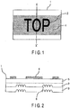
- FIG. 5 is a perspective view showing, in an enlarging manner, an example of a structure that can be employed in the relief-structured region 6 of the display shown in FIGS. 1 and 2 .
- the relief-structured region 6 shown in FIG. 5 is provided with the protruding portions 8.
- the relief-structured region 6 is constituted only by the protruding portions 8 here, this is merely an example.
- the relief-structured region 6 can be formed using recessed portions.
- 1st-order diffracted light is the most representative diffracted light.
- d represents a center-to-center distance of the recessed or protruding portions
- ⁇ represents a wavelength of the incident light and the diffracted light.
- ⁇ represents the angle of emergence of the 0-order diffracted light, i.e., the transmitted light or the regular reflected light.
- the angle of emergence ⁇ of the 1st-order diffracted light changes according to the wavelength ⁇ . That is, the relief structure-forming layer has a function as a spectroscope. Accordingly, in the case where the illumination light is white light, when the observation angle for the relief structure-forming layer is changed, the color perceived by the observer will be changed.
- the color perceived by the observer under a certain observation condition changes according to the grating constant d.
- the relief structure-forming layer emits 1st-order diffracted light in the normal direction thereof. That is, it is assumed that the angle of emergence ⁇ of the 1st-order diffracted light is 0°. Further, it is assumed that the observer perceives this 1st-order diffracted light.
- the formula (1) can be simplified to the following formula (2).
- the relief-structured region is constituted by the recessed or protruding portions arranged two-dimensionally, has low reflectivity and low diffusibility under a normal illumination condition, and exhibits a diffracted light-emitting property under a specific condition. Since the relief-structured region has low reflectivity and low diffusibility under the normal illumination condition, a color with low degrees of lightness and chromaticness such as black and dark gray is perceived under the normal illumination condition. On the other hand, since it has the diffracted light-emitting property under the specific condition, it has the diffracted light-emitting property when observed under the specific condition.
- normal illumination condition refers to a condition in which light from illumination light enters a surface of a substrate almost perpendicularly under illumination light, for example, that from a fluorescent lamp and an observer visually observes the display in an ordinary indoor environment, or a condition in which light from illumination light enters a surface of a substrate almost perpendicularly under illumination light such as sunlight and an observer visually observes the display in an outdoor environment.
- normal illumination light refers to the illumination light in the normal illumination condition.
- specific condition means a condition in which light from illumination light enters a surface of a display almost horizontally, i.e., at an acute angle, and an observer visually observes the display.
- the relief structure-forming layer when the display is observed in the normal direction thereof, the relief structure-forming layer is seen black.
- black means that the reflectance for any of the light components within a wavelength range of 400 nm to 700 nm is 25% or less when the display 1 is irradiated with light from the normal direction and the intensity of the regular reflected light is measured.
- the relief structure-forming layer is seen as if it is a black printed layer. Dark gray with low degrees of lightness and chroma is perceived when the reflectance is about 25% or less, while a sufficient antireflection effect is achieved and thus black is perceived when the reflectance is 10% or less, although it varies depending on the environment of observation and individual differences.
- the angle of emergence of the 1st-order diffracted light from the relief structure-forming layer falls within a range of -90° to 90°, if the angle formed by the normal to the display and the observation direction is set appropriately, the observer can perceive the 1st-order diffracted light from the relief structure-forming layer.
- the relief structure-forming layer is different from a black printed layer.
- the relief structure-forming layer including the relief-structured region can greatly decrease the reflectance for regular reflected light with respect to incident light and can allow visible light to be emitted as reflection-diffracted light by the periodicity of the arrangement of the recessed or protruding portions in a specific direction depending on the incident angle of the incident light.
- the relief-structured region coexists with the region in which the printed layer is formed. Both display images which an observer perceives.
- Such an effect cannot be achieved only by a printed layer and cannot be achieved even by a combination of a printed layer and a diffraction grating pattern. Since the aforementioned effect is achieved by the combination of the relief structure-forming layer including the relief-structured region and the printed layer, a visual effect that cannot be achieved by conventional displays is produced, and thus it becomes possible to obtain the forgery prevention effect.
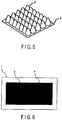
- the region 9 painted over in solid black is perceived as merely a rectangle as shown in FIG. 6
- the rectangular region 9 is divided into a character portion displayed by the relief structure-forming layer including the relief-structured region 6 and a portion surrounded by the character portion and displayed by the printed layer, and thus the information that cannot be recognized under the normal illumination condition can be obtained.
- a functional ink capable of changing its color according to the observation angle can be used.
- the functional ink capable of changing its color according to the observation angle include so-called optical variable inks, color shift inks and pearl inks.
- the optical variable inks and the color shift inks have a function of color change, for example, from red to green or from blue to violet according to the observation angle, while the pearl inks have a function of displaying light pearl-like color at a specific angle.
- both the relief structure-forming layer and the printed layer can exhibit color change according to the observation angle.
- the color change can be perceived easily, and thus the descrimination between a genuine article and a non-genuine article can be performed with reliability.
- the relief structure-forming layer including the relief-structured region according to the present invention has a function of switching between a black or dark gray display and a display utilizing color of diffracted light depending on the observation angle, when a functional ink exhibiting the color change is used as the ink for forming the printed layer, both the relief structure-forming layer and the printed layer can exhibit color change according to the observation angle, and thus a higher forgery prevention effect can be obtained.
- the angle at which the change between the black or dark gray display by the relief structure-forming layer including the relief-structured region and the display utilizing color of diffracted light occurs is made equal to the angle at which the color of the functional ink changes, both change can be perceived simultaneously, thus a higher forgery prevention effect can be achieved as compared with a display in which only one of them is present, and the descrimination between a genuine article and a non-genuine article can be performed with a higher degree of reliability.
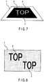
- the character portion displayed by the relief structure-forming layer (relief-structured region 6) and the character portion displayed by the printed layer 4 are perceived as different colors as shown in FIG. 8
- the specific condition for example, under a condition that the display 1 is inclined, each of the character portion displayed by the relief structure-forming layer (relief-structured region 6) and the character portion displayed by the printed layer 4 changes to a different color.
- a latent image pattern As a printing technique exerting a forgery prevention effect, a latent image pattern is known. A display image of the latent image pattern cannot be recognized under a normal illumination condition, and the concealed display image becomes recognizable, for example, when a display is inclined at a predetermined angle.
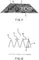
- the construction of the latent image pattern generally employed is the construction in which the concealed image 10 and the peripheral portion 11 are constituted by fine lines intersecting at right angles as shown in FIG. 10 .
- the pitch of the fine lines is about 3 to 10 lines per 1 mm.
- the image constituted as such is hard to distinguish the vertical lines and the horizontal lines intersecting at right angles unde the normal illumination condition, thus is difficult of recognizing the image (in FIG. 10 , the pitch of the fine lines are depicted greater than that of the actual one, and thus the image is recognizable).
- the relief structure-forming layer according to the embodiment of the present invention has a function of switching between a black or dark gray display and a display and a display utilizing color of diffracted light depending on the observation angle, when a latent image pattern is formed by the printed layer, the color change according to the observation angle and the change of the displayed image according to the observation angle caused by the latent image pattern can be mutually compatible, and thus a higher forgery prevention effect can be obtained.
- the angle and the direction at which the change between the black or dark gray display by the relief structure-forming layer including the rerief-structured region and the display utilizing color of diffracted light occurs are made equal to the angle and the direction at which the concealed image by the latent image pattern appears, both changes can be observed simultaneously, a higher forgery prevention effect can be achieved as compared with the display in which only one of them is present, and the descrimination between a genuine article and a non-genuine article can be performed with a higher degree of reliability.
- the latent image pattern (concealed image 10) cannot be recognized as shown in FIG. 10 ; and when the observation angle is changed, the latent image pattern (concealed image 10) appears as shown in FIG. 11 and the diffracted light from the relief structure-forming layer including the relief-structured region can be observed.
- a surface area of the single recessed or protruding portion is equal to or greater than 1.5 times an occupied area necessary for placing the single recessed or protruding portion on the surface of the relief structure-forming layer.
- the surface area of the single recessed or protruding portion is equal to or greater than 1.5 times the occupied area, excellent low-reflectivity and low-diffusibility can be obtained. That is, black is recognized when observed visually.
- the case where the surface area of the single recessed or protruding portion is less than 1.5 times the occupied area is not preferable because the reflectance is high similar to the properties of a flat surface.
- a shape that can be employed for the recessed or protruding portions formed on the relief structure-forming layer include a circular cone shape, a pyramid shape, an elliptic cone shape, a cylindrical column or circular cylinder shape, a prism or rectangular cylinder shape, a truncated circular cone shape, a truncated prism shape, a truncated elliptic cone shape, a shape obtained by joining a cylindrical column or circular cylinder and a circular cone together, a shape obtained by joining a prism or rectangular cylinder and a pyramid together, a semi-sphereshape, a semi-ellipse shape, a bullet shape and a bowl shape.
- the cross sections of the recessed or protruding portions formed on the relief structure-forming layer have a tapered shape.
- the cross sections of the recessed or protruding portions have a tapered shape, the property of demolding a resin from a stamper made of metal is excellent, and thus a high degree of mass productivity can be achieved.
- the cross sections of the recessed or protruding portions have a tapered shape, higher degrees of low-reflectivity and low-diffusibility can be achieved as compared with the case where the cross sections of the recessed or protruding portions have a rectangular shape.
- a tapered shape refers to the case where a recessed or protruding portion is formed such that a cross-sectional area thereof parallel with a surface of a substrate decreases from the base end toward the tip.
- FIG. 12 is an enlarged cross-sectional view of a relief structure-forming layer 2 (relief-structured region 6) in which the recessed or protruding portions have a truncated shape.
- the flat surfaces 12 on the truncated tops of the recessed or protruding portions increase the regular reflectance.
- the width d1 of the flat surfaces 12 is set 90 nm or less, the regular reflected component caused by the flat surfaces can be decreased sufficiently, and thus black can be displayed on the relief structure-forming layer. That is, black can be displayed at almost the same degree as in the case where the width d1 of the flat surfaces is 0 nm.
- the relief-structured region can be obtained to have desired optical properties, and thus processing such as electron bean drawing and etching and a volume production can be performed easily.
- FIGS. 13 and 14 are plan views each schematically showing an example of an arrangement pattern of the recessed or protruding portions that can be employed in the relief structure-forming layer (relief-structured region 6).
- the recessed or protruding portions 13 are arranged in a matrix form at a predetermined center-to-center distance.
- This structure is comparatively easy to manufacture using a fine processing apparatus such as an electron beam drawing apparatus or a stepper and also comparatively easy to precisely control the center-to-center distance of the recessed or protruding portions, etc.
- the recessed or protruding portions are arranged regularly. Accordingly, when the center-to-center distance of the recessed or protruding portions 13 is set 200 nm or more, it is possible to allow the relief-structured region 6 to emit diffracted light. In this case, it is possible to visually confirm that the relief-structured region 6 is different from a black printed layer.
- the center-to-center distance of the recessed or protruding portions 13 is set less than 200 nm, emission of diffracted light from the relief-structured region 6 can be prevented. In this case, in terms of the observed color, it becomes difficult to visually confirm that the relief-structured region 6 is different from a black printed layer.
- the recessed or protruding portions 13 are arranged in a honeycomb form at a predetermined center-to-center distance. This structure can make the area occupied by the recessed or protruding portions 13 small, and thus reflection of light can be prevented more efficiently.
- the arrangement pattern of the recessed or protruding portions is not limited to the above described matrix or honeycomb form. It may be an arrangement pattern having other periodicities such as a rectangular lattice.
- the center-to-center distance of the adjacent recessed or protruding portions of the relief structure-forming layer including the relief-structured region is 400 nm or less, it is possible to prevent any diffracted light within a wavelength range of 400 to 700 nm, which is the visible light range, from being emitted in the normal direction regardless of the incident angle of the illumination light.
- the light of 400 nm is barely able to travel in the normal direction when illuminated at 89°.
- the recessed or protruding portions cannot emit diffracted light toward the front at sufficient intensity within substantially the whole visible range of wave length. That is, diffracted light is emitted at an angle greatly different from the normal direction, and thus diffracted light can be observed only when it is greatly inclined with respect to the normal direction.
- center-to-center distance means the distance d2 between the central axes of the adjacent recessed or protruding portions shown in FIG. 12 .
- the center-to-center distance of the recessed or protruding portions is 250 nm or more and 300 nm or less, as for the visible wavelength range of 400 to 700 nm, diffracted light corresponding to at least the red component cannot be observed on the relief structure-forming layer.
- the relief structure-forming layer does not emit diffracted light in the direction normal to the display and emits diffracted light at an angle greatly different from the normal direction similar to the case where the center-to-center distance is 400 nm or less, no diffraction occurs at the visible light wavelength corresponding to red and diffraction occurs only at the visible light wavelength corresponding to blue and green, and thus it is possible to display only the color that does not change between the rainbow colors as a conventional hologram but is similar to blue and green.
- the height of the recessed or protruding portions in the direction perpendicular to the surface of the substrate is 200 nm or more and 600 nm or less.
- the reflectance increases as the properties of a flat surface, and thus it is impossible to impart sufficient low-reflectivity and low-diffusibility.
- the height is more than 600 nm, replicating the relief structure-forming layer is difficult.
- the height of the recessed or protruding portions means the height h1 of the recessed or protruding portions shown in FIG. 12 .
- the relief structure-forming layer including the relief-structured region can make the recessed or protruding portions give different phase retardations to P-polarized light and S-polarized light, and thus is possible to exhibit a polarizing property.
- the diffracted light emitted by the relief structure-forming layer having a polarizing property is observed through a polarizing plate, it is possible to see that switching between a state where diffracted light is visible and a state where no diffracted light is visible occurs according to the polarizing direction of the polarizing plate.
- the polarizing property of the relief structure-forming layer allows the descrimination between a genuine article and a non-genuine article using a polarizing plate, and thus the forgery prevention effect is further enhanced.
- the relief structure-forming layer may be provided with a diffraction grating pattern region adjacent to the relief-structured region.
- a diffraction grating pattern region adjacent to the relief-structured region.
- a diffraction grating pattern display which is used with and adhered to a security emits diffracted light due to a light-reflecting layer made of, for example, aluminum and a diffraction grating structure, and thus has an effect of iridescence. Under such an observation condition that no diffracted light is emitted toward the observer, only a metallic luster (for example, gold or silver) of the light-reflecting layer is perceived.
- the display including the relief-structured region and the diffraction grating pattern region can display black or dark gray that a conventional diffraction grating pattern display cannot display, a visual effect different from that of a conventional diffraction pattern display can be obtained.
- the relief-structured region and the diffraction grating pattern region are relief structure having a concavo-convex cross section, it is possible to provide a single master with both structures so as to form the relief structure-forming layer including the relief-structured region and the diffraction gratig pattern region on the substrate in a single step.
- FIG. 15 is a plan view schematically showing an example of an information-printed matter 100 including the display 1 according to the present invention.
- the information-printed matter including the display 1 is not limited to this.
- the information printed matter including the display 1 may be other cards such as a wireless card, a magnetic card, an ID (identification) card, and the like.
- multiple forgery prevention measures including a function of the display 1 which allows for visual verification of genuineness and a function of the IC 20 in which encrypted information is recorded and which allows for non-visual verification of genuineness, and thus the forgery prevention performance of the information-printed matter is enhanced.
- the information-printed matter 100 includes a second printed layer 30 in addition to the display 1, and visual comparison between the second printed layer 30 and the display 1 is easy. Therefore, an article whose genuineness is uncertain can be easily descriminated between a genuine article and a non-genuine article as compared with the case where the information-printed matter 100 does not include the second printed layer 30.
- the second printed layer 30 has the same function as that of the printed layer according to the present invention, the printed layer used in the display 1 and the second printed layer 30 do not necessarily require the same function.
- the information-printed matter including the display 1 may be a security such as a gift certificate, a stock certificate and a check.
- the information-printed matter 100 including the display 1 may be a tag to be attached to an article, which is to be confirmed as a genuine article.
- the information-printed matter 100 including the display 1 may be a package or a part thereof for accommodating an article to be confirmed as a genuine article.
- the display 1 is adhered to the pirinted matter substrate 50
- the display 1 can be supported by the substrate by other methods.
- the display 1 may be embeded in the paper, and the paper may be opened at a position corresponding to the display 1.
- the display 1 may be used for a purpose other than forgery prevention.
- the display 1 can also be utilized as a toy, a learning material, a decorative article, etc.
Applications Claiming Priority (3)
| Application Number | Priority Date | Filing Date | Title |
|---|---|---|---|
| JP2007138808 | 2007-05-25 | ||
| JP2007152730 | 2007-06-08 | ||
| PCT/JP2007/072134 WO2008146422A1 (ja) | 2007-05-25 | 2007-11-14 | 表示体及び情報印刷物 |
Publications (4)
| Publication Number | Publication Date |
|---|---|
| EP2157458A1 EP2157458A1 (en) | 2010-02-24 |
| EP2157458A4 EP2157458A4 (en) | 2012-08-15 |
| EP2157458B1 EP2157458B1 (en) | 2013-11-06 |
| EP2157458B2 true EP2157458B2 (en) | 2021-05-26 |
Family
ID=40074700
Family Applications (1)
| Application Number | Title | Priority Date | Filing Date |
|---|---|---|---|
| EP07831864.9A Active EP2157458B2 (en) | 2007-05-25 | 2007-11-14 | Display and information-printed matter |
Country Status (8)
| Country | Link |
|---|---|
| US (2) | US9266371B2 (zh) |
| EP (1) | EP2157458B2 (zh) |
| JP (2) | JP4420138B2 (zh) |
| KR (1) | KR101126938B1 (zh) |
| CN (1) | CN101680978B (zh) |
| BR (2) | BR122018011175B1 (zh) |
| CA (1) | CA2686460C (zh) |
| WO (1) | WO2008146422A1 (zh) |
Families Citing this family (44)
| Publication number | Priority date | Publication date | Assignee | Title |
|---|---|---|---|---|
| WO2008146422A1 (ja) | 2007-05-25 | 2008-12-04 | Toppan Printing Co., Ltd. | 表示体及び情報印刷物 |
| JPWO2009040960A1 (ja) * | 2007-09-28 | 2011-01-13 | 凸版印刷株式会社 | 表示体及びラベル付き物品 |
| CN101746209B (zh) * | 2008-12-17 | 2013-04-17 | 中国人民银行印制科学技术研究所 | 具有光变防伪图案的防伪元件 |
| JP2010197798A (ja) * | 2009-02-26 | 2010-09-09 | Toppan Printing Co Ltd | 偽造防止機能を有する光学素子及びそれを具備する偽造防止表示体 |
| JP5371043B2 (ja) * | 2009-06-01 | 2013-12-18 | 小林クリエイト株式会社 | 改ざん防止印刷物 |
| JP5316231B2 (ja) * | 2009-06-04 | 2013-10-16 | 凸版印刷株式会社 | 表示体及び情報印刷物 |
| JP5504732B2 (ja) * | 2009-07-30 | 2014-05-28 | 凸版印刷株式会社 | 表示体及びラベル付き物品 |
| JP5758069B2 (ja) * | 2009-09-30 | 2015-08-05 | 大日本印刷株式会社 | シート材および容器 |
| JP5143855B2 (ja) * | 2010-04-08 | 2013-02-13 | 凸版印刷株式会社 | 表示体及びラベル付き物品 |
| EP3730978A1 (en) | 2009-12-01 | 2020-10-28 | Toppan Printing Co., Ltd. | Display and labeled article |
| JP5720099B2 (ja) * | 2010-02-05 | 2015-05-20 | 凸版印刷株式会社 | 表示体及び表示体付き物品及び原版の製造方法及びスタンパの製造方法及び表示体の製造方法 |
| JP5740811B2 (ja) * | 2009-12-09 | 2015-07-01 | 凸版印刷株式会社 | 表示体及び表示体付き物品 |
| EP2585862B8 (en) | 2010-06-25 | 2017-10-11 | Andrew Richard Parker | Optical effect structures |
| CN101885402B (zh) * | 2010-08-07 | 2012-08-22 | 湖北金三峡印务有限公司 | 直接模压潜像防伪包装材料及其制备方法 |
| JP5793852B2 (ja) * | 2010-11-10 | 2015-10-14 | 凸版印刷株式会社 | 表示体及び表示体付き物品 |
| JP5659800B2 (ja) * | 2011-01-11 | 2015-01-28 | 大日本印刷株式会社 | ホログラムシート |
| JP5659820B2 (ja) * | 2011-01-24 | 2015-01-28 | 大日本印刷株式会社 | ホログラムシート |
| JP6382482B2 (ja) * | 2011-06-16 | 2018-08-29 | 大日本印刷株式会社 | 回折格子記録媒体 |
| CN102903298B (zh) * | 2011-07-25 | 2015-08-05 | 中钞特种防伪科技有限公司 | 具有表面微浮雕结构的金属镀层防伪膜 |
| JP5938963B2 (ja) * | 2012-03-16 | 2016-06-22 | 凸版印刷株式会社 | 表示体及びラベル付き物品 |
| FR2992255B1 (fr) | 2012-06-22 | 2015-09-04 | Arjowiggins Security | Element de securite et document securise. |
| JP6171291B2 (ja) * | 2012-09-07 | 2017-08-02 | 凸版印刷株式会社 | 表示体の真偽判定方法 |
| JP6003450B2 (ja) * | 2012-09-20 | 2016-10-05 | 凸版印刷株式会社 | 表示体及びラベル付き物品 |
| US9417366B2 (en) * | 2013-07-30 | 2016-08-16 | Northrop Grumman Systems Corporation | Hybrid diffractive optical element and spectral beam combination grating |
| JP6308422B2 (ja) * | 2014-01-20 | 2018-04-11 | 大日本印刷株式会社 | 表示体 |
| KR101602285B1 (ko) * | 2014-02-28 | 2016-03-10 | 한국알프스 주식회사 | 다중인쇄필름 및 이를 이용한 차량용 다중 조명 스위치 |
| CN107111022B (zh) * | 2015-01-08 | 2020-05-12 | 凸版印刷株式会社 | 显示体及物品 |
| WO2016114360A1 (ja) | 2015-01-15 | 2016-07-21 | 凸版印刷株式会社 | 光学素子、物品、および、光学素子の製造方法 |
| CN104574696B (zh) * | 2015-01-30 | 2017-06-16 | 余炳顺 | 一种银行自动柜员机身份认证的方法和系统 |
| JP2016206589A (ja) * | 2015-04-28 | 2016-12-08 | 凸版印刷株式会社 | 表示体およびラベル付き物品 |
| JP6520359B2 (ja) * | 2015-04-30 | 2019-05-29 | 凸版印刷株式会社 | 表示体、物品、原版、および、原版の製造方法 |
| JP6365986B2 (ja) * | 2015-05-13 | 2018-08-01 | 独立行政法人 国立印刷局 | 特殊潜像模様形成体 |
| JP6324346B2 (ja) * | 2015-05-14 | 2018-05-16 | 凸版印刷株式会社 | 表示体及び印刷物 |
| JPWO2016194385A1 (ja) * | 2015-06-02 | 2018-06-07 | 凸版印刷株式会社 | 積層体およびその製造方法 |
| JP6676951B2 (ja) | 2015-07-15 | 2020-04-08 | 凸版印刷株式会社 | 表示体 |
| CN107850708B (zh) | 2015-07-15 | 2022-03-22 | 凸版印刷株式会社 | 显示体 |
| JP2017116732A (ja) * | 2015-12-24 | 2017-06-29 | 株式会社サカイヤ | 加飾シートに回折格子を形成する方法 |
| CN108422764A (zh) * | 2017-02-15 | 2018-08-21 | 中钞特种防伪科技有限公司 | 光学防伪元件及光学防伪产品 |
| DE102017004065A1 (de) * | 2017-04-27 | 2018-10-31 | Giesecke+Devrient Currency Technology Gmbh | Verfahren zur Herstellung eines Sicherheitselements |
| WO2018216700A1 (ja) | 2017-05-22 | 2018-11-29 | 凸版印刷株式会社 | 情報記録体、および、個人証明体 |
| DE102018005474A1 (de) * | 2018-07-09 | 2020-01-09 | Giesecke+Devrient Currency Technology Gmbh | Optisch variables Sicherheitselement mit reflektivem Flächenbereich |
| JP6766860B2 (ja) * | 2018-12-06 | 2020-10-14 | 凸版印刷株式会社 | 表示体及び表示体の製造方法 |
| WO2020195367A1 (ja) * | 2019-03-28 | 2020-10-01 | 凸版印刷株式会社 | 表示体 |
| CN113785229B (zh) | 2019-04-28 | 2023-11-17 | 镭亚股份有限公司 | 制造衍射背光的方法 |
Citations (2)
| Publication number | Priority date | Publication date | Assignee | Title |
|---|---|---|---|---|
| WO2005010661A2 (en) † | 2003-06-26 | 2005-02-03 | Spectra Logic Corporation | Magazine-based data cartridge library |
| WO2005100096A1 (de) † | 2004-04-07 | 2005-10-27 | Leonhard Kurz Gmbh & Co. Kg | Prägefolie zur herstellung fälschungssicherer kraftfahrzeug-nummernschilder und fälschungssicheres kraftfahrzeug-nummernschild mit einer solchen prägefolie |
Family Cites Families (36)
| Publication number | Priority date | Publication date | Assignee | Title |
|---|---|---|---|---|
| US5135812A (en) | 1979-12-28 | 1992-08-04 | Flex Products, Inc. | Optically variable thin film flake and collection of the same |
| US5766738A (en) | 1979-12-28 | 1998-06-16 | Flex Products, Inc. | Paired optically variable article with paired optically variable structures and ink, paint and foil incorporating the same and method |
| EP0201323B1 (en) | 1985-05-07 | 1994-08-17 | Dai Nippon Insatsu Kabushiki Kaisha | Article incorporating a transparent hologramm |
| JPH0812285B2 (ja) | 1988-09-07 | 1996-02-07 | 凸版印刷株式会社 | 回折格子パターンを有するディスプレイとその作製方法 |
| CH677905A5 (zh) | 1989-02-20 | 1991-07-15 | Orell Fuessli Graph Betr Ag | |
| DE3932505C2 (de) | 1989-09-28 | 2001-03-15 | Gao Ges Automation Org | Datenträger mit einem optisch variablen Element |
| GB8924111D0 (en) | 1989-10-26 | 1989-12-13 | Amblehurst Ltd | Optical device |
| WO1992001973A2 (en) * | 1990-07-20 | 1992-02-06 | Mcgrew Stephen P | Embossing tool |
| GB9106128D0 (en) | 1991-03-22 | 1991-05-08 | Amblehurst Ltd | Article |
| JPH07108788A (ja) | 1993-10-08 | 1995-04-25 | Toppan Printing Co Ltd | 表示体およびその製造に用いる転写箔 |
| DE4334847A1 (de) | 1993-10-13 | 1995-04-20 | Kurz Leonhard Fa | Wertdokument mit Fenster |
| CN1106344A (zh) * | 1994-02-05 | 1995-08-09 | 苏斌 | 防伪造的平面标记和防复印、翻摄伪造的平面标记 |
| DE19541064A1 (de) * | 1995-11-03 | 1997-05-07 | Giesecke & Devrient Gmbh | Datenträger mit einem optisch variablen Element |
| DE19611383A1 (de) | 1996-03-22 | 1997-09-25 | Giesecke & Devrient Gmbh | Datenträger mit optisch variablem Element |
| GB9810399D0 (en) * | 1998-05-14 | 1998-07-15 | Rue De Int Ltd | Holographic security device |
| US6761959B1 (en) | 1999-07-08 | 2004-07-13 | Flex Products, Inc. | Diffractive surfaces with color shifting backgrounds |
| DE10127980C1 (de) * | 2001-06-08 | 2003-01-16 | Ovd Kinegram Ag Zug | Diffraktives Sicherheitselement |
| DE10150293B4 (de) | 2001-10-12 | 2005-05-12 | Ovd Kinegram Ag | Sicherheitselement |
| DE10226114A1 (de) | 2001-12-21 | 2003-07-03 | Giesecke & Devrient Gmbh | Sicherheitselement für Sicherheitspapiere und Wertdokumente |
| ITMI20020064A1 (it) | 2002-01-15 | 2003-07-15 | Elmiva S A S Di Walter Mategaz | Elemento di sicurezza contro la contraffazione e la falsificazione del tipo ologramma e simili per documenti in genere |
| JP4324374B2 (ja) * | 2002-03-29 | 2009-09-02 | 大日本印刷株式会社 | 微細凹凸パターン形成材料、微細凹凸パターン形成方法、転写箔、光学物品及びスタンパー |
| JP2004358925A (ja) | 2003-06-09 | 2004-12-24 | Dainippon Printing Co Ltd | 表面装飾用転写シート、物品の表面装飾方法および装飾物品 |
| JP4275469B2 (ja) * | 2003-06-16 | 2009-06-10 | 大日本印刷株式会社 | 凹凸パターン形成材料、凹凸パターン受容体、凹凸パターン形成方法、転写箔、及び光学物品 |
| JP4275468B2 (ja) * | 2003-06-16 | 2009-06-10 | 大日本印刷株式会社 | 凹凸パターン形成材料、凹凸パターン受容体、凹凸パターン形成方法、転写箔、及び光学物品 |
| DE10333469A1 (de) * | 2003-07-22 | 2005-02-10 | Giesecke & Devrient Gmbh | Sicherheitselement |
| JP2005101231A (ja) * | 2003-09-24 | 2005-04-14 | Kyocera Corp | 電子部品用セラミック基板 |
| AT504572A1 (de) | 2004-03-26 | 2008-06-15 | Hueck Folien Gmbh | Folienmaterial mit optischen merkmalen |
| EP1744904B2 (de) * | 2004-04-30 | 2019-11-06 | Giesecke+Devrient Currency Technology GmbH | Folienmaterial und verfahren zu seiner herstellung |
| US20070211238A1 (en) | 2004-04-30 | 2007-09-13 | Giesecke & Devrient Gmbh | Security Element and Methods for the Production Thereof |
| WO2005106601A2 (en) | 2004-04-30 | 2005-11-10 | De La Rue International Limited | Arrays of microlenses and arrays of microimages on transparent security substrates |
| EP1652688A1 (en) | 2004-10-29 | 2006-05-03 | Arjowiggins Security | Security device |
| JP2006153990A (ja) * | 2004-11-25 | 2006-06-15 | Dainippon Printing Co Ltd | 真正性識別体および真正性識別可能な基材 |
| JP2006171605A (ja) * | 2004-12-20 | 2006-06-29 | Toppan Printing Co Ltd | ホログラムラベルの製造方法およびホログラムラベル |
| JP2007072188A (ja) | 2005-09-07 | 2007-03-22 | Dainippon Printing Co Ltd | ホログラム、ホログラムラベル及びホログラム転写箔 |
| JP4676843B2 (ja) | 2005-09-07 | 2011-04-27 | 大日本印刷株式会社 | 印刷及びホログラム付きパウチシートの製造方法 |
| WO2008146422A1 (ja) | 2007-05-25 | 2008-12-04 | Toppan Printing Co., Ltd. | 表示体及び情報印刷物 |
-
2007
- 2007-11-14 WO PCT/JP2007/072134 patent/WO2008146422A1/ja active Application Filing
- 2007-11-14 JP JP2009516152A patent/JP4420138B2/ja active Active
- 2007-11-14 CA CA2686460A patent/CA2686460C/en active Active
- 2007-11-14 KR KR1020097024519A patent/KR101126938B1/ko active IP Right Grant
- 2007-11-14 BR BR122018011175-5A patent/BR122018011175B1/pt active IP Right Grant
- 2007-11-14 BR BRPI0721636-0A2A patent/BRPI0721636A2/pt not_active Application Discontinuation
- 2007-11-14 CN CN2007800531210A patent/CN101680978B/zh active Active
- 2007-11-14 EP EP07831864.9A patent/EP2157458B2/en active Active
-
2009
- 2009-11-25 US US12/592,523 patent/US9266371B2/en active Active
- 2009-12-10 JP JP2009280137A patent/JP4888545B2/ja active Active
-
2016
- 2016-01-14 US US14/995,824 patent/US9933551B2/en active Active
Patent Citations (2)
| Publication number | Priority date | Publication date | Assignee | Title |
|---|---|---|---|---|
| WO2005010661A2 (en) † | 2003-06-26 | 2005-02-03 | Spectra Logic Corporation | Magazine-based data cartridge library |
| WO2005100096A1 (de) † | 2004-04-07 | 2005-10-27 | Leonhard Kurz Gmbh & Co. Kg | Prägefolie zur herstellung fälschungssicherer kraftfahrzeug-nummernschilder und fälschungssicheres kraftfahrzeug-nummernschild mit einer solchen prägefolie |
Also Published As
| Publication number | Publication date |
|---|---|
| JP4420138B2 (ja) | 2010-02-24 |
| EP2157458A4 (en) | 2012-08-15 |
| BR122018011175B1 (pt) | 2021-02-02 |
| JP4888545B2 (ja) | 2012-02-29 |
| CA2686460C (en) | 2012-05-01 |
| BRPI0721636A2 (pt) | 2014-02-18 |
| US9933551B2 (en) | 2018-04-03 |
| EP2157458A1 (en) | 2010-02-24 |
| US20100080938A1 (en) | 2010-04-01 |
| CN101680978A (zh) | 2010-03-24 |
| KR101126938B1 (ko) | 2012-03-20 |
| KR20090130329A (ko) | 2009-12-22 |
| US20160121641A1 (en) | 2016-05-05 |
| US9266371B2 (en) | 2016-02-23 |
| EP2157458B1 (en) | 2013-11-06 |
| CA2686460A1 (en) | 2008-12-04 |
| WO2008146422A1 (ja) | 2008-12-04 |
| JPWO2008146422A1 (ja) | 2010-08-19 |
| JP2010052437A (ja) | 2010-03-11 |
| CN101680978B (zh) | 2012-05-30 |
Similar Documents
| Publication | Publication Date | Title |
|---|---|---|
| EP2157458B2 (en) | Display and information-printed matter | |
| US10843419B2 (en) | Display and labeled article | |
| US8147945B2 (en) | Display and labeled article | |
| JP5303879B2 (ja) | 表示体及びラベル付き物品 | |
| KR102219805B1 (ko) | 표시체 | |
| JP5338177B2 (ja) | 表示体及びラベル付き物品 | |
| JP2012123102A (ja) | 表示体及びラベル付き物品 | |
| JP5082378B2 (ja) | 表示体及び印刷物 | |
| JP5834466B2 (ja) | 表示体及び情報印刷物 | |
| JP5407511B2 (ja) | 表示体及び情報印刷物 | |
| JP5994899B2 (ja) | 表示体及びラベル付き物品 | |
| JP2017032900A (ja) | 表示体及び表示体付き物品 | |
| JP2016218093A (ja) | 表示体 |
Legal Events
| Date | Code | Title | Description |
|---|---|---|---|
| PUAI | Public reference made under article 153(3) epc to a published international application that has entered the european phase |
Free format text: ORIGINAL CODE: 0009012 |
|
| 17P | Request for examination filed |
Effective date: 20091105 |
|
| AK | Designated contracting states |
Kind code of ref document: A1 Designated state(s): AT BE BG CH CY CZ DE DK EE ES FI FR GB GR HU IE IS IT LI LT LU LV MC MT NL PL PT RO SE SI SK TR |
|
| AX | Request for extension of the european patent |
Extension state: AL BA HR MK RS |
|
| DAX | Request for extension of the european patent (deleted) | ||
| A4 | Supplementary search report drawn up and despatched |
Effective date: 20120716 |
|
| RIC1 | Information provided on ipc code assigned before grant |
Ipc: B41M 3/14 20060101AFI20120710BHEP Ipc: G09F 3/02 20060101ALI20120710BHEP Ipc: G02B 5/18 20060101ALI20120710BHEP Ipc: B42D 15/00 20060101ALI20120710BHEP Ipc: G09F 3/03 20060101ALI20120710BHEP |
|
| 17Q | First examination report despatched |
Effective date: 20120820 |
|
| REG | Reference to a national code |
Ref country code: DE Ref legal event code: R079 Ref document number: 602007033711 Country of ref document: DE Free format text: PREVIOUS MAIN CLASS: G02B0005180000 Ipc: G02B0027420000 |
|
| GRAP | Despatch of communication of intention to grant a patent |
Free format text: ORIGINAL CODE: EPIDOSNIGR1 |
|
| RIC1 | Information provided on ipc code assigned before grant |
Ipc: G02B 5/18 20060101ALI20130419BHEP Ipc: G02B 27/42 20060101AFI20130419BHEP Ipc: B41M 3/14 20060101ALI20130419BHEP Ipc: G09F 3/02 20060101ALI20130419BHEP Ipc: G09F 3/03 20060101ALI20130419BHEP Ipc: B42D 15/00 20060101ALI20130419BHEP |
|
| INTG | Intention to grant announced |
Effective date: 20130524 |
|
| GRAS | Grant fee paid |
Free format text: ORIGINAL CODE: EPIDOSNIGR3 |
|
| GRAA | (expected) grant |
Free format text: ORIGINAL CODE: 0009210 |
|
| STAA | Information on the status of an ep patent application or granted ep patent |
Free format text: STATUS: THE PATENT HAS BEEN GRANTED |
|
| AK | Designated contracting states |
Kind code of ref document: B1 Designated state(s): AT BE BG CH CY CZ DE DK EE ES FI FR GB GR HU IE IS IT LI LT LU LV MC MT NL PL PT RO SE SI SK TR |
|
| REG | Reference to a national code |
Ref country code: GB Ref legal event code: FG4D |
|
| REG | Reference to a national code |
Ref country code: CH Ref legal event code: NV Representative=s name: E. BLUM AND CO. AG PATENT- UND MARKENANWAELTE , CH Ref country code: CH Ref legal event code: EP |
|
| REG | Reference to a national code |
Ref country code: AT Ref legal event code: REF Ref document number: 639852 Country of ref document: AT Kind code of ref document: T Effective date: 20131215 |
|
| REG | Reference to a national code |
Ref country code: IE Ref legal event code: FG4D |
|
| REG | Reference to a national code |
Ref country code: DE Ref legal event code: R096 Ref document number: 602007033711 Country of ref document: DE Effective date: 20140102 |
|
| REG | Reference to a national code |
Ref country code: NL Ref legal event code: VDEP Effective date: 20131106 |
|
| REG | Reference to a national code |
Ref country code: AT Ref legal event code: MK05 Ref document number: 639852 Country of ref document: AT Kind code of ref document: T Effective date: 20131106 |
|
| REG | Reference to a national code |
Ref country code: LT Ref legal event code: MG4D |
|
| PG25 | Lapsed in a contracting state [announced via postgrant information from national office to epo] |
Ref country code: NL Free format text: LAPSE BECAUSE OF FAILURE TO SUBMIT A TRANSLATION OF THE DESCRIPTION OR TO PAY THE FEE WITHIN THE PRESCRIBED TIME-LIMIT Effective date: 20131106 Ref country code: LT Free format text: LAPSE BECAUSE OF FAILURE TO SUBMIT A TRANSLATION OF THE DESCRIPTION OR TO PAY THE FEE WITHIN THE PRESCRIBED TIME-LIMIT Effective date: 20131106 Ref country code: FI Free format text: LAPSE BECAUSE OF FAILURE TO SUBMIT A TRANSLATION OF THE DESCRIPTION OR TO PAY THE FEE WITHIN THE PRESCRIBED TIME-LIMIT Effective date: 20131106 Ref country code: SE Free format text: LAPSE BECAUSE OF FAILURE TO SUBMIT A TRANSLATION OF THE DESCRIPTION OR TO PAY THE FEE WITHIN THE PRESCRIBED TIME-LIMIT Effective date: 20131106 Ref country code: IS Free format text: LAPSE BECAUSE OF FAILURE TO SUBMIT A TRANSLATION OF THE DESCRIPTION OR TO PAY THE FEE WITHIN THE PRESCRIBED TIME-LIMIT Effective date: 20140306 |
|
| PG25 | Lapsed in a contracting state [announced via postgrant information from national office to epo] |
Ref country code: BE Free format text: LAPSE BECAUSE OF FAILURE TO SUBMIT A TRANSLATION OF THE DESCRIPTION OR TO PAY THE FEE WITHIN THE PRESCRIBED TIME-LIMIT Effective date: 20131106 Ref country code: AT Free format text: LAPSE BECAUSE OF FAILURE TO SUBMIT A TRANSLATION OF THE DESCRIPTION OR TO PAY THE FEE WITHIN THE PRESCRIBED TIME-LIMIT Effective date: 20131106 Ref country code: LV Free format text: LAPSE BECAUSE OF FAILURE TO SUBMIT A TRANSLATION OF THE DESCRIPTION OR TO PAY THE FEE WITHIN THE PRESCRIBED TIME-LIMIT Effective date: 20131106 Ref country code: ES Free format text: LAPSE BECAUSE OF FAILURE TO SUBMIT A TRANSLATION OF THE DESCRIPTION OR TO PAY THE FEE WITHIN THE PRESCRIBED TIME-LIMIT Effective date: 20131106 |
|
| PG25 | Lapsed in a contracting state [announced via postgrant information from national office to epo] |
Ref country code: PT Free format text: LAPSE BECAUSE OF FAILURE TO SUBMIT A TRANSLATION OF THE DESCRIPTION OR TO PAY THE FEE WITHIN THE PRESCRIBED TIME-LIMIT Effective date: 20140306 |
|
| PG25 | Lapsed in a contracting state [announced via postgrant information from national office to epo] |
Ref country code: EE Free format text: LAPSE BECAUSE OF FAILURE TO SUBMIT A TRANSLATION OF THE DESCRIPTION OR TO PAY THE FEE WITHIN THE PRESCRIBED TIME-LIMIT Effective date: 20131106 |
|
| REG | Reference to a national code |
Ref country code: DE Ref legal event code: R026 Ref document number: 602007033711 Country of ref document: DE |
|
| PLBI | Opposition filed |
Free format text: ORIGINAL CODE: 0009260 |
|
| REG | Reference to a national code |
Ref country code: IE Ref legal event code: MM4A |
|
| PG25 | Lapsed in a contracting state [announced via postgrant information from national office to epo] |
Ref country code: MC Free format text: LAPSE BECAUSE OF FAILURE TO SUBMIT A TRANSLATION OF THE DESCRIPTION OR TO PAY THE FEE WITHIN THE PRESCRIBED TIME-LIMIT Effective date: 20131106 Ref country code: IT Free format text: LAPSE BECAUSE OF FAILURE TO SUBMIT A TRANSLATION OF THE DESCRIPTION OR TO PAY THE FEE WITHIN THE PRESCRIBED TIME-LIMIT Effective date: 20131106 Ref country code: RO Free format text: LAPSE BECAUSE OF FAILURE TO SUBMIT A TRANSLATION OF THE DESCRIPTION OR TO PAY THE FEE WITHIN THE PRESCRIBED TIME-LIMIT Effective date: 20131106 Ref country code: CZ Free format text: LAPSE BECAUSE OF FAILURE TO SUBMIT A TRANSLATION OF THE DESCRIPTION OR TO PAY THE FEE WITHIN THE PRESCRIBED TIME-LIMIT Effective date: 20131106 Ref country code: SK Free format text: LAPSE BECAUSE OF FAILURE TO SUBMIT A TRANSLATION OF THE DESCRIPTION OR TO PAY THE FEE WITHIN THE PRESCRIBED TIME-LIMIT Effective date: 20131106 Ref country code: PL Free format text: LAPSE BECAUSE OF FAILURE TO SUBMIT A TRANSLATION OF THE DESCRIPTION OR TO PAY THE FEE WITHIN THE PRESCRIBED TIME-LIMIT Effective date: 20131106 |
|
| PLAX | Notice of opposition and request to file observation + time limit sent |
Free format text: ORIGINAL CODE: EPIDOSNOBS2 |
|
| 26 | Opposition filed |
Opponent name: LEONHARD KURZ STIFTUNG & CO. KG Effective date: 20140806 |
|
| PG25 | Lapsed in a contracting state [announced via postgrant information from national office to epo] |
Ref country code: DK Free format text: LAPSE BECAUSE OF FAILURE TO SUBMIT A TRANSLATION OF THE DESCRIPTION OR TO PAY THE FEE WITHIN THE PRESCRIBED TIME-LIMIT Effective date: 20131106 |
|
| REG | Reference to a national code |
Ref country code: DE Ref legal event code: R026 Ref document number: 602007033711 Country of ref document: DE Effective date: 20140806 |
|
| REG | Reference to a national code |
Ref country code: FR Ref legal event code: ST Effective date: 20140917 |
|
| PG25 | Lapsed in a contracting state [announced via postgrant information from national office to epo] |
Ref country code: IE Free format text: LAPSE BECAUSE OF NON-PAYMENT OF DUE FEES Effective date: 20131114 |
|
| PG25 | Lapsed in a contracting state [announced via postgrant information from national office to epo] |
Ref country code: FR Free format text: LAPSE BECAUSE OF NON-PAYMENT OF DUE FEES Effective date: 20140106 |
|
| PLAF | Information modified related to communication of a notice of opposition and request to file observations + time limit |
Free format text: ORIGINAL CODE: EPIDOSCOBS2 |
|
| PG25 | Lapsed in a contracting state [announced via postgrant information from national office to epo] |
Ref country code: SI Free format text: LAPSE BECAUSE OF FAILURE TO SUBMIT A TRANSLATION OF THE DESCRIPTION OR TO PAY THE FEE WITHIN THE PRESCRIBED TIME-LIMIT Effective date: 20131106 |
|
| PLBB | Reply of patent proprietor to notice(s) of opposition received |
Free format text: ORIGINAL CODE: EPIDOSNOBS3 |
|
| PG25 | Lapsed in a contracting state [announced via postgrant information from national office to epo] |
Ref country code: TR Free format text: LAPSE BECAUSE OF FAILURE TO SUBMIT A TRANSLATION OF THE DESCRIPTION OR TO PAY THE FEE WITHIN THE PRESCRIBED TIME-LIMIT Effective date: 20131106 Ref country code: CY Free format text: LAPSE BECAUSE OF FAILURE TO SUBMIT A TRANSLATION OF THE DESCRIPTION OR TO PAY THE FEE WITHIN THE PRESCRIBED TIME-LIMIT Effective date: 20131106 |
|
| PG25 | Lapsed in a contracting state [announced via postgrant information from national office to epo] |
Ref country code: LU Free format text: LAPSE BECAUSE OF NON-PAYMENT OF DUE FEES Effective date: 20131114 Ref country code: HU Free format text: LAPSE BECAUSE OF FAILURE TO SUBMIT A TRANSLATION OF THE DESCRIPTION OR TO PAY THE FEE WITHIN THE PRESCRIBED TIME-LIMIT; INVALID AB INITIO Effective date: 20071114 Ref country code: BG Free format text: LAPSE BECAUSE OF FAILURE TO SUBMIT A TRANSLATION OF THE DESCRIPTION OR TO PAY THE FEE WITHIN THE PRESCRIBED TIME-LIMIT Effective date: 20131106 |
|
| PG25 | Lapsed in a contracting state [announced via postgrant information from national office to epo] |
Ref country code: MT Free format text: LAPSE BECAUSE OF FAILURE TO SUBMIT A TRANSLATION OF THE DESCRIPTION OR TO PAY THE FEE WITHIN THE PRESCRIBED TIME-LIMIT Effective date: 20131106 Ref country code: GR Free format text: LAPSE BECAUSE OF NON-PAYMENT OF DUE FEES Effective date: 20131106 |
|
| PG25 | Lapsed in a contracting state [announced via postgrant information from national office to epo] |
Ref country code: GR Free format text: LAPSE BECAUSE OF FAILURE TO SUBMIT A TRANSLATION OF THE DESCRIPTION OR TO PAY THE FEE WITHIN THE PRESCRIBED TIME-LIMIT Effective date: 20140207 |
|
| RIC2 | Information provided on ipc code assigned after grant |
Ipc: B41M 3/14 20060101ALI20160621BHEP Ipc: B42D 25/328 20140101ALI20160621BHEP Ipc: B42D 25/29 20140101AFI20160621BHEP Ipc: G02B 5/18 20060101ALI20160621BHEP Ipc: G09F 3/03 20060101ALI20160621BHEP Ipc: G09F 3/02 20060101ALI20160621BHEP Ipc: G02B 27/42 20060101ALI20160621BHEP |
|
| APAH | Appeal reference modified |
Free format text: ORIGINAL CODE: EPIDOSCREFNO |
|
| APBM | Appeal reference recorded |
Free format text: ORIGINAL CODE: EPIDOSNREFNO |
|
| APBP | Date of receipt of notice of appeal recorded |
Free format text: ORIGINAL CODE: EPIDOSNNOA2O |
|
| APBQ | Date of receipt of statement of grounds of appeal recorded |
Free format text: ORIGINAL CODE: EPIDOSNNOA3O |
|
| APBU | Appeal procedure closed |
Free format text: ORIGINAL CODE: EPIDOSNNOA9O |
|
| PUAH | Patent maintained in amended form |
Free format text: ORIGINAL CODE: 0009272 |
|
| STAA | Information on the status of an ep patent application or granted ep patent |
Free format text: STATUS: PATENT MAINTAINED AS AMENDED |
|
| REG | Reference to a national code |
Ref country code: CH Ref legal event code: AELC |
|
| 27A | Patent maintained in amended form |
Effective date: 20210526 |
|
| AK | Designated contracting states |
Kind code of ref document: B2 Designated state(s): AT BE BG CH CY CZ DE DK EE ES FI FR GB GR HU IE IS IT LI LT LU LV MC MT NL PL PT RO SE SI SK TR |
|
| REG | Reference to a national code |
Ref country code: DE Ref legal event code: R102 Ref document number: 602007033711 Country of ref document: DE |
|
| P01 | Opt-out of the competence of the unified patent court (upc) registered |
Effective date: 20230530 |
|
| PGFP | Annual fee paid to national office [announced via postgrant information from national office to epo] |
Ref country code: GB Payment date: 20230928 Year of fee payment: 17 |
|
| PGFP | Annual fee paid to national office [announced via postgrant information from national office to epo] |
Ref country code: DE Payment date: 20230929 Year of fee payment: 17 Ref country code: CH Payment date: 20231201 Year of fee payment: 17 |