EP2124278A1 - Séparateur de pile à combustible, procédé de séparation de pile à combustible et pile à combustible - Google Patents
Séparateur de pile à combustible, procédé de séparation de pile à combustible et pile à combustible Download PDFInfo
- Publication number
- EP2124278A1 EP2124278A1 EP08711595A EP08711595A EP2124278A1 EP 2124278 A1 EP2124278 A1 EP 2124278A1 EP 08711595 A EP08711595 A EP 08711595A EP 08711595 A EP08711595 A EP 08711595A EP 2124278 A1 EP2124278 A1 EP 2124278A1
- Authority
- EP
- European Patent Office
- Prior art keywords
- fuel cell
- cell separator
- amorphous carbon
- sections
- carbon layer
- Prior art date
- Legal status (The legal status is an assumption and is not a legal conclusion. Google has not performed a legal analysis and makes no representation as to the accuracy of the status listed.)
- Granted
Links
- 239000000446 fuel Substances 0.000 title claims abstract description 157
- 238000004519 manufacturing process Methods 0.000 title claims description 25
- 239000010410 layer Substances 0.000 claims abstract description 174
- OKTJSMMVPCPJKN-UHFFFAOYSA-N Carbon Chemical compound [C] OKTJSMMVPCPJKN-UHFFFAOYSA-N 0.000 claims abstract description 119
- 229910003481 amorphous carbon Inorganic materials 0.000 claims abstract description 107
- 229910002804 graphite Inorganic materials 0.000 claims abstract description 98
- 239000010439 graphite Substances 0.000 claims abstract description 98
- 229910052751 metal Inorganic materials 0.000 claims abstract description 97
- 239000002184 metal Substances 0.000 claims abstract description 97
- 239000000758 substrate Substances 0.000 claims abstract description 93
- 239000011247 coating layer Substances 0.000 claims abstract description 56
- 239000002245 particle Substances 0.000 claims abstract description 43
- RTAQQCXQSZGOHL-UHFFFAOYSA-N Titanium Chemical group [Ti] RTAQQCXQSZGOHL-UHFFFAOYSA-N 0.000 claims description 41
- 239000010936 titanium Substances 0.000 claims description 41
- 229910052719 titanium Inorganic materials 0.000 claims description 41
- 238000000034 method Methods 0.000 claims description 39
- 239000000463 material Substances 0.000 claims description 34
- 238000007733 ion plating Methods 0.000 claims description 31
- 238000005260 corrosion Methods 0.000 claims description 30
- 230000007797 corrosion Effects 0.000 claims description 27
- 238000005240 physical vapour deposition Methods 0.000 claims description 13
- 230000015572 biosynthetic process Effects 0.000 claims description 10
- 238000005229 chemical vapour deposition Methods 0.000 claims description 10
- 230000000052 comparative effect Effects 0.000 description 28
- 238000009792 diffusion process Methods 0.000 description 25
- 238000004088 simulation Methods 0.000 description 24
- 238000010248 power generation Methods 0.000 description 19
- 229910052799 carbon Inorganic materials 0.000 description 18
- 229910000510 noble metal Inorganic materials 0.000 description 14
- 239000003792 electrolyte Substances 0.000 description 13
- 239000012495 reaction gas Substances 0.000 description 13
- 239000007789 gas Substances 0.000 description 11
- 239000002994 raw material Substances 0.000 description 10
- 239000003575 carbonaceous material Substances 0.000 description 9
- VNWKTOKETHGBQD-UHFFFAOYSA-N methane Chemical compound C VNWKTOKETHGBQD-UHFFFAOYSA-N 0.000 description 9
- 239000003054 catalyst Substances 0.000 description 7
- 238000010891 electric arc Methods 0.000 description 7
- 238000005259 measurement Methods 0.000 description 7
- 238000001878 scanning electron micrograph Methods 0.000 description 7
- 238000004544 sputter deposition Methods 0.000 description 7
- 229910052737 gold Inorganic materials 0.000 description 6
- 238000005268 plasma chemical vapour deposition Methods 0.000 description 6
- 238000007747 plating Methods 0.000 description 6
- 229910052697 platinum Inorganic materials 0.000 description 6
- 230000032798 delamination Effects 0.000 description 5
- RYGMFSIKBFXOCR-UHFFFAOYSA-N Copper Chemical compound [Cu] RYGMFSIKBFXOCR-UHFFFAOYSA-N 0.000 description 4
- 238000006243 chemical reaction Methods 0.000 description 4
- 229910052802 copper Inorganic materials 0.000 description 4
- 239000010949 copper Substances 0.000 description 4
- 238000001704 evaporation Methods 0.000 description 4
- 239000001257 hydrogen Substances 0.000 description 4
- 229910052739 hydrogen Inorganic materials 0.000 description 4
- 239000007787 solid Substances 0.000 description 4
- 238000001237 Raman spectrum Methods 0.000 description 3
- 239000002041 carbon nanotube Substances 0.000 description 3
- 229910021393 carbon nanotube Inorganic materials 0.000 description 3
- -1 hydrogen ions Chemical class 0.000 description 3
- 239000011364 vaporized material Substances 0.000 description 3
- NWUYHJFMYQTDRP-UHFFFAOYSA-N 1,2-bis(ethenyl)benzene;1-ethenyl-2-ethylbenzene;styrene Chemical compound C=CC1=CC=CC=C1.CCC1=CC=CC=C1C=C.C=CC1=CC=CC=C1C=C NWUYHJFMYQTDRP-UHFFFAOYSA-N 0.000 description 2
- 229910000838 Al alloy Inorganic materials 0.000 description 2
- XKRFYHLGVUSROY-UHFFFAOYSA-N Argon Chemical compound [Ar] XKRFYHLGVUSROY-UHFFFAOYSA-N 0.000 description 2
- 239000004215 Carbon black (E152) Substances 0.000 description 2
- VYZAMTAEIAYCRO-UHFFFAOYSA-N Chromium Chemical compound [Cr] VYZAMTAEIAYCRO-UHFFFAOYSA-N 0.000 description 2
- 229910000881 Cu alloy Inorganic materials 0.000 description 2
- MYMOFIZGZYHOMD-UHFFFAOYSA-N Dioxygen Chemical compound O=O MYMOFIZGZYHOMD-UHFFFAOYSA-N 0.000 description 2
- OTMSDBZUPAUEDD-UHFFFAOYSA-N Ethane Chemical compound CC OTMSDBZUPAUEDD-UHFFFAOYSA-N 0.000 description 2
- UFHFLCQGNIYNRP-UHFFFAOYSA-N Hydrogen Chemical compound [H][H] UFHFLCQGNIYNRP-UHFFFAOYSA-N 0.000 description 2
- 229910001069 Ti alloy Inorganic materials 0.000 description 2
- 239000002390 adhesive tape Substances 0.000 description 2
- 229910052782 aluminium Inorganic materials 0.000 description 2
- XAGFODPZIPBFFR-UHFFFAOYSA-N aluminium Chemical compound [Al] XAGFODPZIPBFFR-UHFFFAOYSA-N 0.000 description 2
- 239000002131 composite material Substances 0.000 description 2
- 150000001875 compounds Chemical class 0.000 description 2
- 229910001882 dioxygen Inorganic materials 0.000 description 2
- 230000000694 effects Effects 0.000 description 2
- 229930195733 hydrocarbon Natural products 0.000 description 2
- 150000002430 hydrocarbons Chemical class 0.000 description 2
- 239000003456 ion exchange resin Substances 0.000 description 2
- 229920003303 ion-exchange polymer Polymers 0.000 description 2
- 239000007788 liquid Substances 0.000 description 2
- 238000001000 micrograph Methods 0.000 description 2
- 239000010935 stainless steel Substances 0.000 description 2
- 229910001220 stainless steel Inorganic materials 0.000 description 2
- 239000000126 substance Substances 0.000 description 2
- 238000001069 Raman spectroscopy Methods 0.000 description 1
- GWEVSGVZZGPLCZ-UHFFFAOYSA-N Titan oxide Chemical compound O=[Ti]=O GWEVSGVZZGPLCZ-UHFFFAOYSA-N 0.000 description 1
- 239000002253 acid Substances 0.000 description 1
- 238000004458 analytical method Methods 0.000 description 1
- 229910052786 argon Inorganic materials 0.000 description 1
- 125000004432 carbon atom Chemical group C* 0.000 description 1
- 239000004020 conductor Substances 0.000 description 1
- 230000008878 coupling Effects 0.000 description 1
- 238000010168 coupling process Methods 0.000 description 1
- 238000005859 coupling reaction Methods 0.000 description 1
- 230000007547 defect Effects 0.000 description 1
- 230000006866 deterioration Effects 0.000 description 1
- 238000010828 elution Methods 0.000 description 1
- 238000005516 engineering process Methods 0.000 description 1
- UQSQSQZYBQSBJZ-UHFFFAOYSA-N fluorosulfonic acid Chemical compound OS(F)(=O)=O UQSQSQZYBQSBJZ-UHFFFAOYSA-N 0.000 description 1
- 229910052741 iridium Inorganic materials 0.000 description 1
- 230000000873 masking effect Effects 0.000 description 1
- 229910021645 metal ion Inorganic materials 0.000 description 1
- 239000007769 metal material Substances 0.000 description 1
- 229910044991 metal oxide Inorganic materials 0.000 description 1
- 150000004706 metal oxides Chemical class 0.000 description 1
- FGHSTPNOXKDLKU-UHFFFAOYSA-N nitric acid;hydrate Chemical compound O.O[N+]([O-])=O FGHSTPNOXKDLKU-UHFFFAOYSA-N 0.000 description 1
- 238000001020 plasma etching Methods 0.000 description 1
- 229910052709 silver Inorganic materials 0.000 description 1
- 238000004611 spectroscopical analysis Methods 0.000 description 1
- 238000001308 synthesis method Methods 0.000 description 1
- OGIDPMRJRNCKJF-UHFFFAOYSA-N titanium oxide Inorganic materials [Ti]=O OGIDPMRJRNCKJF-UHFFFAOYSA-N 0.000 description 1
- 229910052720 vanadium Inorganic materials 0.000 description 1
- 238000004832 voltammetry Methods 0.000 description 1
- XLYOFNOQVPJJNP-UHFFFAOYSA-N water Substances O XLYOFNOQVPJJNP-UHFFFAOYSA-N 0.000 description 1
Images


Classifications
-
- H—ELECTRICITY
- H01—ELECTRIC ELEMENTS
- H01M—PROCESSES OR MEANS, e.g. BATTERIES, FOR THE DIRECT CONVERSION OF CHEMICAL ENERGY INTO ELECTRICAL ENERGY
- H01M8/00—Fuel cells; Manufacture thereof
- H01M8/02—Details
-
- H—ELECTRICITY
- H01—ELECTRIC ELEMENTS
- H01M—PROCESSES OR MEANS, e.g. BATTERIES, FOR THE DIRECT CONVERSION OF CHEMICAL ENERGY INTO ELECTRICAL ENERGY
- H01M8/00—Fuel cells; Manufacture thereof
- H01M8/02—Details
- H01M8/0202—Collectors; Separators, e.g. bipolar separators; Interconnectors
- H01M8/0204—Non-porous and characterised by the material
- H01M8/0206—Metals or alloys
-
- H—ELECTRICITY
- H01—ELECTRIC ELEMENTS
- H01M—PROCESSES OR MEANS, e.g. BATTERIES, FOR THE DIRECT CONVERSION OF CHEMICAL ENERGY INTO ELECTRICAL ENERGY
- H01M8/00—Fuel cells; Manufacture thereof
- H01M8/02—Details
- H01M8/0202—Collectors; Separators, e.g. bipolar separators; Interconnectors
- H01M8/0204—Non-porous and characterised by the material
- H01M8/0213—Gas-impermeable carbon-containing materials
-
- H—ELECTRICITY
- H01—ELECTRIC ELEMENTS
- H01M—PROCESSES OR MEANS, e.g. BATTERIES, FOR THE DIRECT CONVERSION OF CHEMICAL ENERGY INTO ELECTRICAL ENERGY
- H01M8/00—Fuel cells; Manufacture thereof
- H01M8/02—Details
- H01M8/0202—Collectors; Separators, e.g. bipolar separators; Interconnectors
- H01M8/0204—Non-porous and characterised by the material
- H01M8/0223—Composites
- H01M8/0226—Composites in the form of mixtures
-
- H—ELECTRICITY
- H01—ELECTRIC ELEMENTS
- H01M—PROCESSES OR MEANS, e.g. BATTERIES, FOR THE DIRECT CONVERSION OF CHEMICAL ENERGY INTO ELECTRICAL ENERGY
- H01M8/00—Fuel cells; Manufacture thereof
- H01M8/02—Details
- H01M8/0202—Collectors; Separators, e.g. bipolar separators; Interconnectors
- H01M8/0204—Non-porous and characterised by the material
- H01M8/0223—Composites
- H01M8/0228—Composites in the form of layered or coated products
-
- H—ELECTRICITY
- H01—ELECTRIC ELEMENTS
- H01M—PROCESSES OR MEANS, e.g. BATTERIES, FOR THE DIRECT CONVERSION OF CHEMICAL ENERGY INTO ELECTRICAL ENERGY
- H01M8/00—Fuel cells; Manufacture thereof
- H01M8/04—Auxiliary arrangements, e.g. for control of pressure or for circulation of fluids
-
- Y—GENERAL TAGGING OF NEW TECHNOLOGICAL DEVELOPMENTS; GENERAL TAGGING OF CROSS-SECTIONAL TECHNOLOGIES SPANNING OVER SEVERAL SECTIONS OF THE IPC; TECHNICAL SUBJECTS COVERED BY FORMER USPC CROSS-REFERENCE ART COLLECTIONS [XRACs] AND DIGESTS
- Y02—TECHNOLOGIES OR APPLICATIONS FOR MITIGATION OR ADAPTATION AGAINST CLIMATE CHANGE
- Y02E—REDUCTION OF GREENHOUSE GAS [GHG] EMISSIONS, RELATED TO ENERGY GENERATION, TRANSMISSION OR DISTRIBUTION
- Y02E60/00—Enabling technologies; Technologies with a potential or indirect contribution to GHG emissions mitigation
- Y02E60/30—Hydrogen technology
- Y02E60/50—Fuel cells
-
- Y—GENERAL TAGGING OF NEW TECHNOLOGICAL DEVELOPMENTS; GENERAL TAGGING OF CROSS-SECTIONAL TECHNOLOGIES SPANNING OVER SEVERAL SECTIONS OF THE IPC; TECHNICAL SUBJECTS COVERED BY FORMER USPC CROSS-REFERENCE ART COLLECTIONS [XRACs] AND DIGESTS
- Y02—TECHNOLOGIES OR APPLICATIONS FOR MITIGATION OR ADAPTATION AGAINST CLIMATE CHANGE
- Y02P—CLIMATE CHANGE MITIGATION TECHNOLOGIES IN THE PRODUCTION OR PROCESSING OF GOODS
- Y02P70/00—Climate change mitigation technologies in the production process for final industrial or consumer products
- Y02P70/50—Manufacturing or production processes characterised by the final manufactured product
Definitions
- the present invention relates to technologies of a fuel cell separator, a manufacturing method of the fuel cell separator, and a fuel cell.
- a fuel cell has an electrolyte film, a pair of electrodes (an anode and a cathode) each including a catalyst layer and a diffusion layer, and a pair of fuel cell separators (an anode side separator and a cathode side separator) that sandwich the electrodes therebetween.
- an anode gas supplied to the anode is a hydrogen gas
- a cathode gas supplied to the cathode is an oxygen gas
- a reaction of producing hydrogen ions and electrons proceeds on the anode side, and the hydrogen ions reach the cathode side through the electrolyte film, whereas the electrons reach the cathode through an external circuit.
- the cathode side the hydrogen ions, the electrons, and the oxygen gas react to generate water, thereby emitting energy.
- Examples of the fuel cell separator include a separator having a substrate formed of carbon, and a separator having a substrate formed of a metal.
- the fuel cell separator having the substrate formed of the metal is superior in mechanical strength and moldability as compared with the fuel cell separator having the substrate formed of carbon.
- the fuel cell generates moisture during power generation, and hence the fuel cell separator having the substrate formed of the metal is apt to corrode as compared with the fuel cell separator having the substrate formed of carbon.
- contact resistance increases, which may result in deterioration in the performance of the fuel cell.
- the contact resistance of the fuel cell separator means both a similar material contact resistance (a contact resistance between similar fuel cell separators) and a diffusion layer contact resistance (a contact resistance between the fuel cell separator and the diffusion layer).
- a fuel cell separator having a metal substrate subjected t plating of a noble metal such as Au or Pt.
- a noble metal such as Au or Pt.
- the noble metals are expensive, and the plating requires use of a large amount of the noble metal, which is not practical.
- the corrosion of the metal substrate can be suppressed by forming a graphite layer on the metal substrate, but the formation of the graphite metal thereon is technically difficult.
- a booklet of International Publication No. 01-006585 discloses a fuel cell separator having a metal substrate coated with diamond-like carbon to suppress the corrosion of the metal substrate.
- JP 2003-123781 A discloses a fuel cell separator having a metal substrate coated with diamond-like carbon containing a metal to suppress the corrosion of the metal substrate.
- JP 2002-151110 A discloses a fuel cell separator in which an oxide layer is formed on a metal substrate and a conductive layer is further formed on a surface of the oxide layer to suppress the corrosion of the metal substrate and an increase in the contact resistance of the fuel cell separator.
- JP 2000-164228 A discloses a fuel cell separator in which a low-electric resistance layer and an anti-corrosion layer are formed on a metal substrate surface to suppress the corrosion of the metal substrate and the increase in the contact resistance of the fuel cell separator.
- JP 2001-283872 A discloses a fuel cell separator in which carbon particles dispersed in the manners of islands on a metal substrate are coupled with an upper side of the metal substrate through a chrome carbide layer to suppress the increase in the contact resistance of the fuel cell separator.
- the diamond-like carbon corrodes depending on a power generation environment; e.g., an operating temperature of the fuel cell (e.g., 70°C or above), moisture generated at the time of power generation, or a potential difference involved in a power generation reaction, with the result that the contact resistance of the fuel cell separator inconveniently increases.
- a power generation environment e.g., an operating temperature of the fuel cell (e.g., 70°C or above), moisture generated at the time of power generation, or a potential difference involved in a power generation reaction.
- the metal corrodes together with the diamond-like carbon depending on a power generation environment of the fuel cell, and consequently the metal is turned to a metal oxide, with the result that the contact resistance of the fuel cell separator increases further.
- metal materials are used for all of the conductive layer, the low-electric resistance layer, and the anti-corrosion layer, and hence the conductive layer, the low-electric resistance layer, and the anti-corrosion layer corrode depending on a power generation environment of each fuel cell, thereby increasing the contact resistance of each fuel cell separator.
- An object of the present invention is to provide a fuel cell separator which can suppress the corrosion of a metal substrate and inhibit an increase in contact resistance of the fuel cell separator even in a fuel cell power generation environment; e.g., an operating temperature of the fuel cell (e.g., 70°C or above), moisture generated at the time of power generation, or a potential difference involved in a power generation reaction; a manufacturing method of the fuel cell separator; and a fuel cell including the fuel cell separator.
- the coating layer on the metal substrate is constituted of the amorphous carbon layer and conductive sections, whereby there can be provided the fuel cell separator which can suppress the corrosion of the metal substrate and inhibit an increase in contact resistance of the fuel cell separator even in the fuel cell power generation environment, and the fuel cell including the fuel cell separator.
- the manufacturing method of the fuel cell separator which includes an amorphous carbon layer forming step of forming the amorphous carbon layer on the metal substrate by means of a physical vapor deposition method or a chemical vapor deposition method, and a conductive sections forming step of forming the conductive sections on the amorphous carbon layer by means of a method equivalent to or different from the physical vapor deposition method or the chemical vapor deposition method, whereby the corrosion of the metal substrate can be suppressed and an increase in the contact resistance of the fuel cell separator can be inhibited even in the fuel cell power generation environment.
- FIG. 1 is a schematic cross-sectional view showing an example configuration of a fuel cell according to an embodiment of the present invention.
- a fuel cell 1 includes an electrolyte film 10, an anode 12, a cathode 14, and fuel cell separators 16.
- the electrolyte film 10 is, e.g., a perfluorosulfoninc acid-based ion-exchange resin film.
- Each of the anode 12 and the cathode 14 is constituted of a diffusion layer using, e.g., carbon paper and a sheet-like catalyst layer in which a noble metal catalyst is carried by a carrier such as carbon.
- the diffusion layer is arranged on the fuel cell separator 16 side, whereas the catalyst layer is arranged on the electrolyte film 10 side.
- the fuel cell 1 includes a film-electrode assembly 18 in which the anode 12 is formed on one surface of the electrolyte film 10 and the cathode 14 is formed on the other surface thereof to sandwich the electrolyte film 10 therebetween and face each other; and a pair of fuel cell separators 16 which hold respective outer sides of the film-electrode assembly 18.
- reaction gas flow paths 20 through which a reaction gas is supplied to the anode 12 or the cathode 14 are formed.
- FIG. 2 is a schematic cross-sectional view showing an example configuration of a fuel cell separator according to this embodiment.
- the fuel cell separator 16 includes a metal substrate 22 having the reaction gas flow paths 20 formed thereon and a coating layer 24 formed on the metal substrate 22.
- a configuration where the coating layer 24 is formed on the metal substrate 22 on the reaction gas flow path 20 side is taken as an example, but the present invention is not restricted thereto.
- the coating layer 24 may be formed on the metal substrate 22 on the opposite side of the reaction gas flow paths 20 (a side opposite the side facing the anode 12 or the cathode 14 shown in FIG. 1 ), or may be formed on the metal substrate 22 on the reaction gas flow path 20 side and the opposite side of the reaction gas flow paths 20.
- FIGS. 3(A) to (D ) is a partially enlarged schematic cross-sectional view of the fuel cell separator shown in FIG. 2 .
- the coating layer 24 include an amorphous carbon layer 26 and conductive sections 28 (or 28a to 28c).
- the amorphous carbon layer 26 serves to mainly suppress the corrosion of the metal substrate 22.
- the conductive sections 28 serve to mainly suppress an increase in contact resistance of the fuel cell separator.
- FIG. 3(A) is a view showing a state where the conductive sections 28 are dispersed and arranged in or on the amorphous carbon layer 26, and each of FIGS. 3(B) to (D is a view showing a state where the conductive sections 28 are arranged on the amorphous carbon layer 26.
- the conductive sections of this embodiment are arranged in at least one of a state where the conductive sections are partially exposed from a surface of the amorphous carbon layer [e.g., the conductive sections 28a shown in FIG. 3(A) ], a state where the entire conductive sections are exposed from the surface of the amorphous carbon layer [the conductive sections 28b shown in FIG. 3(A) and the conductive sections 28 shown in FIGS. 3(B) to (D) ], and a state where the entire conductive sections are embedded in the amorphous carbon layer [the conductive sections 28c shown in FIG. 3(A) ].
- a state where the conductive sections are partially exposed from a surface of the amorphous carbon layer e.g., the conductive sections 28a shown in FIG. 3(A)
- a state where the entire conductive sections are exposed from the surface of the amorphous carbon layer the conductive sections 28b shown in FIG. 3(A) and the conductive sections 28 shown in FIGS. 3(B) to
- a conformation of the conductive sections may be island-like as shown in FIGS. 3(A) and (B) , comb-like as shown in FIG. 3(C) , or layer-like as shown in FIG. 3(D) , and it is not restricted in particular.
- the formation of the coating layer is easy, and hence the conformation of the conductive sections is preferably island-like.
- the conductive sections of this embodiment are formed of a conductive material, and may be formed of, e.g., a noble metal such as Au, Pt, Ag, Ru or Ir, graphite particles (graphite sections), or carbon nanohorns or carbon nanotubes.
- a noble metal such as Au, Pt, Ag, Ru or Ir
- graphite particles graphite sections
- carbon nanohorns or carbon nanotubes In the light of corrosion resistance or conductive properties, the conductive sections are preferably formed of the noble metal or the graphite particles (the graphite sections), and in the light of manufacturing cost, they are more preferably formed of the graphite particles (the graphite sections).
- the conductive sections 28a to 28c shown in FIG. 3(A) are preferably formed of the graphite particles (the graphite sections), because the use of the graphite particles facilitates the formation of the conductive sections.
- the conductive sections 28 shown in FIG. 3(B) are preferably formed of a noble metal such as Au, Pt, Ag, Ru, or Ir, because the use of the noble metal facilitates the formation of the conductive sections.
- the respective conductive sections 28 shown in FIGS. 3(C) and (D) are preferably formed of carbon nanohorns or carbon nanotubes, because the use of the carbon nanohorns or the carbon nanotubes facilitates the formation of the conductive sections.
- the amorphous carbon layer 26 is constituted of amorphous carbon made of graphite (a solid) as a raw material by a known sputtering method, filtered arc ion plating method, or filterless arc ion plating method described later.
- the amorphous carbon layer 26 can be likewise formed using a hydrogen carbide-based compound (a liquid or a gas) as a raw material by a known plasma CVD method or ionized evaporation method.
- a layer constituted of a noble metal the layer being formed using a noble metal such as Au, Pt, Ag, Ru, or Ir as a raw material by, e.g., a known sputtering method, plasma CVD method, ionized evaporation method, or filtered arc ion plating method.
- a preferable configuration of the coating layer 24 is such a configuration of the amorphous carbon layer 26 and the conductive sections 28a to 28c as shown in FIG. 3(A) in which the conductive sections 28a to 28c are formed of the graphite particles (the graphite sections).
- both the amorphous carbon layer 26 and the conductive sections 28a to 28c are formed of the carbon material, the strength of an interface between the amorphous carbon layer and the conductive sections is high. Therefore, the conductive sections are hardly delaminated from the amorphous carbon layer, which makes it possible to suppress an increase in the contact resistance owing to delamination of the conductive sections.
- the coating layer 24 having the amorphous carbon layer 26 and the conductive sections 28a to 28c formed of graphite particles shown in FIG. 3(A) will be described as an example.
- the fuel cell separator includes the metal substrate 22 and the coating layer 24 which has the amorphous carbon layer 26 and the conductive sections 28a to 28c formed of graphite particles (hereinafter may be referred to as graphite sections 28a to 28c).
- the graphite sections of this embodiment are preferably arranged in at least one of a state where the graphite sections are partially exposed from the surface of the amorphous carbon layer [e.g., the conductive sections 28a shown in FIG. 3(A) ], a state where the entire graphite sections are exposed from the surface of the amorphous carbon layer [the conductive section 28b shown in FIG. 3(A) ], and a state where the entire graphite sections are embedded in the amorphous carbon layer [the conductive section 28c shown in FIG. 3(A) ].
- the state where the graphite sections are at least partially exposed from the surface of the amorphous carbon layer is preferable.
- the structure where the graphite sections are held by the amorphous carbon layer i.e., the arrangement in the state where the graphite sections are partially exposed from the amorphous carbon layer and the state where the entire graphite sections are embedded in the amorphous carbon layer.
- the conformation of the graphite sections is island-like, the coating layer can be easily formed, and hence such an island-like conformation is preferable.
- the graphite sections 28a to 28c are formed of graphite particles and have higher crystallinity than the amorphous carbon layer 26.
- the crystallinity is evaluated by calculating an intensity ratio (D/G) of a peak intensity (G) of a peak in a range of 1540 cm -1 to 1560 cm -1 and a peak intensity (D) of a peak in a range of 1370 cm -1 to 1390 cm -1 in Raman spectrum analysis.
- the smaller the intensity ratio (D/G) the higher the crystallinity.
- the Raman spectrum can be measured by means of a known method.
- a sample is irradiated with an argon laser beam having a wavelength of 514.5 nm, and spectrometry is then carried out with respect to light forming an angle of 90 degrees with irradiated light of scattered light from the sample, thereby measuring the Raman spectrum.
- a measurement device there is a laser Raman spectrometric device RAMANOR S-320 manufactured by Jobin Yvon Co. Ltd.
- Graphite sections having particle diameters of less than 1 ⁇ m among the graphite sections 28a to 28c are preferably present in a ratio of 12.6 or more per ⁇ m 2 of the amorphous carbon layer (26).
- the contact resistance of the fuel cell separator may rise in some cases.
- the number of graphite sections having the particle diameters of less than 1 ⁇ m can be obtained by photographing the surface of the amorphous carbon layer in a scanning electron micrograph, and visually counting the graphite sections having particle diameters of less than 1 ⁇ m in an area (e.g., 50 ⁇ m 2 ) of the amorphous carbon layer in the obtained micrograph.
- graphite sections having particle diameters equal to or above 1 ⁇ m to less than 3 ⁇ m among the graphite sections 28a to 28c are preferably present in a ratio of 1.8 or more per ⁇ m 2 of the amorphous carbon layer (26). Moreover, more preferably, graphite sections having particle diameters of 3 ⁇ m or above among the graphite sections 28a to 28c are present in a ratio of 0.1 or more per ⁇ m 2 of the amorphous carbon layer (26).
- the contact resistance of the fuel cell separator may increase in some cases.
- the number of the graphite sections can be measured by the same method as described above.
- the amorphous carbon layer 26 is formed of amorphous carbon (also referred to as diamond-like carbon) having an amorphous coupled state in coupling of carbon atoms. Moreover, an inclusion concentration of hydrogen included when forming the amorphous carbon layer 26 is preferably be less than 1% in terms of resistance. Additionally, a metal may be contained in the amorphous carbon layer 26 in order to increase conductive properties of the amorphous carbon layer 26; the contained metal may corrode in the power generation environment of the fuel cell. Therefore, in this embodiment, preventing a metal from being contained in the amorphous carbon layer 26 is preferable.
- the film thickness of the amorphous carbon layer 26 preferably falls within a range of 30 nm to 10 ⁇ m.
- FIG. 4 is a view showing a relation between a diffusion layer contact resistance of the fuel cell separator and the film thickness of the amorphous carbon layer according to this embodiment. As shown in FIG. 4 , when the film thickness of the amorphous carbon layer is smaller than 30 nm, the diffusion layer contact resistance increases. That is because the island-shaped amorphous carbon layer is formed instead of the film-shaped amorphous carbon layer, when the amorphous carbon layer is formed to a thickness less than 30 nm. Further, when the film thickness is larger than 10 ⁇ m, an impractical fuel cell separator is provided.
- the corrosion current value of the coating layer a value equal to or below 3.0 ⁇ A/cm 2 is preferable, and a value equal to or below 1.5 ⁇ A/cm 2 is more preferable.
- the corrosion current value of the coating layer 24 is higher than 3.0 ⁇ A/cm 2 , the coating layer 24 may be apt to be destroyed in the power generation environment of the fuel cell.
- the material of the metal substrate 22 used in this embodiment a material superior in corrosion resistance is preferable, and one of stainless steel, copper, a copper alloy, aluminum, an aluminum alloy, titanium, and a titanium alloy, or a composite material including these substances can be used, for example. To avoid elution of metal ions, using titanium for the metal substrate is preferable.
- FIG. 5 is a schematic cross-sectional view showing an example configuration of a fuel cell according to another embodiment of the present invention.
- a fuel cell 2 includes an electrolyte film 30, an anode 32, a cathode 34, and fuel cell separators 36.
- the electrolyte film 30 is, e.g., a perfluoro sulfonate-based ion-exchange resin film.
- Each of the anode 32 and the cathode 34 is formed of a diffusion layer using, e.g., carbon paper and a sheet-like catalyst layer in which a noble metal catalyst is carried by a carrier such as carbon, and the diffusion layer is arranged on the fuel cell separator 36 side, whereas the catalyst layer is arranged on the electrolyte film 30 side.
- the fuel cell 2 includes a film-electrode assembly 38 in which the anode 32 is formed on one surface of the electrolyte film 30 and the cathode 34 is formed on the other surface to sandwich the electrolyte film 30 therebetween and face each other and the pair of fuel cell separators 36 that hold both outer sides of the film-electrode assembly 38.
- Reaction gas flow paths 40 through which a gas is supplied to the anode 32 or the cathode 34 are formed on the fuel cell separator 36.
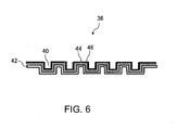
- FIG. 6 is a schematic cross-sectional view showing an example configuration of the fuel cell separator according to another embodiment of the present invention.
- the fuel cell separator 36 includes a metal substrate 42 that has the reaction gas flow paths 40 formed thereon and an intermediate layer 44 and a coating layer 46 that are formed on the metal substrate 42.
- the configuration where the intermediate layer 44 and the coating layer 46 are formed on the metal substrate 42 on the reaction gas flow path 40 side is taken as an example, but the present invention is not restricted thereto.
- the intermediate layer 44 and the coating layer 46 may be formed on the metal substrate 42 on an opposite side (an opposite side of the side facing the anode 32 or the cathode 34 shown in FIG. 5 ) of the reaction gas flow paths 40 or may be formed on the metal substrate 42 on the reaction gas flow path 40 side or on the opposite side of the reaction gas flow paths 40.
- the material of the metal substrate 42 used in this embodiment a material superior in corrosion resistance is preferable, and one of stainless steel, copper, a copper alloy, aluminum, an aluminum alloy, titanium, and a titanium alloy, or a composite material including these substances can be used, for example.
- using titanium as the metal substrate 42 is preferable.
- a titanium layer (the intermediate layer 44) having a higher purity than a titanium purity of the metal substrate 42 is preferably arranged between the metal substrate 42 and the coating layer 46. Adopting such a configuration enables suppressing delamination of the coating layer 46.
- an amount of the metal having a high purity to be used can be suppressed, which is also preferable from the viewpoint of manufacturing cost.
- the titanium layer is formed by, e.g., a sputtering method.
- the film thickness of the titanium layer (the intermediate layer 44) preferably falls within a range of 25 nm to 10 ⁇ m. Since uniformly forming the titanium layer thinner than 25 nm without defects is technically difficult, an oxide layer having a titanium oxide remaining in the metal substrate 42 as a nucleus is generated, whereby the contact resistance of the fuel cell separator may increase or the coating layer 46 may be readily delaminated from the metal substrate 42. When this film thickness is larger than 10 ⁇ m, an impractical fuel cell separator is provided.
- the present invention is not restricted thereto if the metal substrate is changed, and the intermediate layer 44 which is formed of an element constituting the metal substrate and has excellent adhesion with respect to C (carbon) can be used.
- the manufacturing method of the fuel cell separator according to this embodiment includes: an amorphous carbon layer forming step of forming the amorphous carbon layer on the metal substrate by means of the physical vapor deposition method or the chemical vapor deposition method; and conductive sections forming step of forming the conductive sections on the amorphous carbon layer by means of a method equivalent to or different from the physical vapor deposition method or the chemical vapor deposition method.
- the physical vapor deposition method or the chemical vapor deposition method is used to form the amorphous carbon layer on the metal substrate.
- graphite (a solid) or the like can be used as a raw material to form the amorphous carbon layer by, e.g., a known sputtering method, filtered arc ion plating method, or filterless arc ion plating method described later.
- a hydrogen carbide-based compound (a liquid or a gas) can be used as a raw material to form the amorphous carbon layer by a known plasma CVD method or ionized evaporation method.
- the physical vapor deposition method or the chemical vapor deposition method can be used to form the conductive sections on the metal substrate.
- a noble metal such as Au, Pt, Ag, or Co
- a carbon material such as graphite (a solid)
- a carbon material such as graphite (a solid) can be used as a raw material to form graphite sections by, e.g., the later-explained filterless arc ion plating method.
- a noble metal such as Au, Pt, or Ag can be used as a raw material to form the conductive sections consisting of the noble metal by, e.g., the known inkjet method, gas-phase synthesis method, or plating method.
- a hydrocarbon gas such as a methane gas or an ethane gas can be used as a raw material to form the conductive sections by a known plasma CVD method.
- a hydrocarbon gas such as a methane gas or an ethane gas can be used as a raw material to form the conductive sections by a known plasma CVD method or the like, and then the conductive sections are formed into a comb-like conformation by reactive ion etching.
- the physical vapor deposition method of forming the amorphous carbon layer and the conductive sections use of the filterless arc ion plating method among the above-described methods is preferable. Adopting this method enables forming the amorphous carbon layer and forming the graphite sections as the conductive sections, thereby simplifying the manufacturing method. Furthermore, when this method is utilized, the amorphous carbon layer 26 and the graphite sections 28a to 28c such as shown in FIG. 3(A) can be formed.
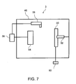
- FIG. 7 is a schematic view showing an example configuration of a filterless arc ion plating apparatus which can form the amorphous carbon layer and the graphite sections by a filterless arc ion plating method.
- the filterless arc ion plating apparatus 3 has a vacuum container 48 evacuated by a vacuum exhaust pump (not shown), a mounting jig 52 which holds a metal substrate 50 as an object to be processed, a target 54 which forms a cathode, an anode 56, an arc power supply 58 connected between the target 54 and the anode 56, and a bias power supply 60 which applies a bias voltage to the metal substrate 50.
- the arc power supply 58 is first activated to effect arc discharge between the anode 56 and the target 54.
- the target 54 locally dissolves and evaporates to be ionized at the same time.
- An ionized material (a material which is obtained when the target evaporates to be ionized, and will hereinafter be referred to as an ionized vaporized material) is accelerated by applying a bias voltage to the metal substrate 50 from the bias power supply 60, and the metal substrate 50 is coated with this accelerated material, thereby forming the amorphous carbon layer.
- the filterless arc ion plating method and a known filtered arc ion plating method can similarly be used.
- the filterless arc ion plating method and the filtered arc ion plating method when the target evaporates to be ionized, molten particles (droplets) are generated. When the molten particles adhere to the metal substrate 50, the uniform amorphous carbon layer cannot be formed. Therefore, in the known filtered arc ion plating method, a filter which prevents the molten particles from passing therethrough (a masking shield) is provided between the metal substrate 50 and the target 54.
- the metal substrate 50 is coated with the ionized vaporized material and the molten particles without using the filter.
- the target 54 used in this embodiment is a carbon material.
- the molten particles generated from the target 54 are graphite having high crystallinity. Accordingly, when the filterless arc ion plating method is used, the ionized vaporized material enables formation of the amorphous carbon layer, and the graphite sections are formed by adhesion of the molten particles to the metal substrate 50.
- the bias voltage applied to the metal substrate 50 preferably falls within a range of 150 V to 1000 V in terms of manufacture of the fuel cell separator having low contact resistance.
- a contact resistance that can be used for the fuel cell separator e.g., 10 m ⁇ cm 2
- the bias voltage applied to the metal substrate 50 preferably falls within a range of 150 V to 250 V or a range of 700 V to 1000 V in terms of manufacture of the fuel cell separator having low contact resistance and a low corrosion current value, and more preferably the same falls within a range of 150 V to 250 V in terms of, e.g., power consumption at the time of manufacturing the fuel cell separator.
- Such a filterless arc ion plating apparatus 3 as shown in FIG. 7 was used to form a coating layer such as shown in FIG. 3(A) .
- a carbon material was used as a target 54 to effect arc discharge between the target 54 and an anode 56, a bias voltage 50 V was applied to a titanium plate as a metal substrate 50, and an amorphous carbon layer and the coating layer having graphite sections as conductive sections were formed on the titanium plate. This was determined as Example 1.
- Examples 2 to 8 application of a bias voltage of 150 V, application of a bias voltage of 200 V, application of a bias voltage of 250 V, application of a bias voltage of 500 V, application of a bias voltage of 750 V, application of a bias voltage of 1000 V, and no application of a bias voltage were performed in place of application of the bias voltage in Example 1.
- a carbon material was used as a target in a sputtering method to form an amorphous carbon layer on a titanium plate, which was a configuration of Comparative Example 1. Moreover, in a filtered arc ion plating method, a carbon material was used as a target, and arc discharge was then effected between the target and an anode to form an amorphous carbon layer, which was a configuration of Comparative Example 2. Additionally, a titanium plate which was plated with Au was a configuration of Comparative Example 3.
- Two separators cut into predetermined dimensions (2 cm x 2 cm) were prepared in accordance with each example, respective surfaces each having the coating layer formed thereon in each example were overlapped, both outer sides of this laminated structure were held by a copper plate, a load of 1 MPa was applied, and a contact resistance (a similar material contact resistance) of the separators in each embodiment was measured by a generally utilized alternating-current four-terminal method (a current 1A).
- each example cut to predetermined dimensions (2 cm x 2 cm) and carbon paper (a diffusion layer) were prepared, a surface having the coating layer formed thereon and the diffusion layer (the carbon paper) in each example were overlapped, both outer sides of this laminated structure were held by a copper plate, a load of 1 MPa was applied, and a contact resistance (a diffusion layer contact resistance) of each example and the diffusion layer was measured by a generally utilized alternating-current four-terminal method (the current 1A). Measurement was performed in each comparative example by means of the same method.
- a counter electrode [a Pt plate (4 cm x 4 cm)], a reference electrode [a Pt plate (4 cm x 4 cm)], and a work electrode [each example (4 cm x 4 cm)] were immersed in 300 ml of a nitric acid water solution (pH 4) serving as an electrolyte at 80°C, and a corrosion current value of each example was measured by using a standard voltammetry tool (SV-100 manufactured by Hokuto Denko Corporation) with a holding potential of 1000 mV (vs. SHE) and a measurement time of 50 hours. Additionally, measurement was also performed with respect to each comparative example by the same method.
- a standard voltammetry tool SV-100 manufactured by Hokuto Denko Corporation
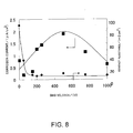
- FIG. 8 is a graph showing results of the contact resistances (the similar material contact resistance + the diffusion layer contact resistance) and the corrosion current value in each of Examples 1 to 8.
- an abscissa in FIG. 8 represents a bias voltage applied to the titanium plate when forming the coating layer in each of Examples 1 to 8, in order to facilitate explanation.
- a value of the similar material contact resistance + the diffusion layer contact resistance in each of Examples 1 to 8 was a value lower than a practical level for the fuel cell separator (e.g., 10 m ⁇ cm 2 or below) (in particular, a range where the bias voltage is 150 to 1000 V [Examples 2 to 7)]. Further, as shown in FIG.
- the corrosion current value in each of Examples 1 to 8 was 2.5 ⁇ A/cm 2 or below, which is a value smaller than a practical level for the fuel cell separator (e.g., 3 ⁇ A/cm 2 or below).
- the corrosion current value was 1.5 ⁇ A/cm 2 or below and the contact resistance was 10 m ⁇ cm 2 or below.
- FIG. 9(A) shows a scanning electron micrograph of Example 2
- FIG. 9(B) shows a scanning electron micrograph of Example 8.
- Example 3 was also photographed in the formed of a scanning electron micrograph (not shown).
- the number of the graphite sections having particle diameters of less than 1 ⁇ m, the number of the graphite sections having particle diameters of 1 ⁇ or above and less than 3 ⁇ , and the number of the graphite sections having particle diameters of 3 ⁇ m or more were visually confirmed from an area of the amorphous carbon layer (50 ⁇ m x 50 ⁇ m) in each obtained micrograph, and Table 1 shows results by conversion of the obtained number into the number per ⁇ m 2 .
- Table 1 The number of graphite sections per ⁇ m 2 of amorphous carbon Particle diameters of less than 1 ⁇ m Particle diameters of 1 or above to less than 3 ⁇ m Particle diameters of 3 ⁇ m or above
- Example 2 bias voltage 150 V 12.6 1.8 0.1
- Example 3 bias voltage 250 V 16.0 2.1 0.3
- Example 8 bias voltage 0 V 4.0 1.2 0.1
- the number of graphite sections increases as the bias voltage rises from 0 V (Example 10) to 150 V (Example 2) and 250 V( Example 3).
- the similar material contact resistance has a lower value (10 m ⁇ cm 2 or below) than that when no bias voltage is applied (Example 10) or when the bias voltage is 50 V (Example 1) (see FIG. 8 ).
- the number of the graphite sections having particle diameters of less than 1 ⁇ m is preferably 12.6/ ⁇ m 2
- the number of the graphite sections having particle diameters of 1 ⁇ or above to less than 3 ⁇ m is preferably 1.8/ ⁇ m 2
- the number of the graphite sections having particle diameters of 3 ⁇ m or above preferably 0.1/ ⁇ m 2 .
- FIG. 10 is a graph showing similar material contact resistances before and after a cell environment simulation test in Example 2 and Comparative Examples 1 to 3.
- the similar material contact resistance after the cell environment simulation test in each of Comparative Examples 1 and 2 increased 1.0 m ⁇ cm 2 or more beyond the similar material contact resistance before the cell environment simulation test.
- Example 2 since Example 2 has the graphite sections, the similar material contact resistance value after the cell environment simulation test in Example 2 increased only 0.2 m ⁇ cm 2 beyond the similar material contact resistance before the cell environment simulation test. This is a value equivalent to that of Comparative Example 3 (a change of 0.1 m ⁇ cm 2 before and after the test in Comparative Example 3) subjected to the plating using At which hardly corrodes.
- FIG. 11 is a graph showing diffusion layer contact resistances before and after the cell environment simulation test in Example 2 and Comparative Examples 1 and 3.
- the diffusion layer contact resistance value after the cell environment simulation test in Comparative Example 1 increased 5.0 m ⁇ cm 2 beyond the diffusion layer contact resistance before the cell environment simulation test.
- the diffusion layer contact resistance after the cell environment simulation test in Example 2 increased only 0.5 m ⁇ cm 2 beyond the diffusion layer contact resistance before the cell environment simulation test. This is a value equivalent to that in Comparative Example 3 (a change of 0.1 m ⁇ cm 2 before and after the test in Comparative Example 3) subjected to the plating using Au which rarely corrodes.
- the above examples each having the graphite sections in the coating layer can suppress an increase in the contact resistance of the fuel cell even in the fuel cell power generation environment.
- Such a filterless arc ion plating apparatus 3 as shown in FIG. 7 was used to form a coating layer as follows.
- a carbon material was used as a target 54, arc discharge was effected between the target 54 and an anode 56, and a bias voltage 150 V was applied to a porous body of titanium as a metal substrate 50 to form an amorphous carbon layer and a coating layer having graphite sections on the porous body of titanium.
- This structure was determined as Example 9.
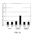
- FIG. 12 is a graph showing similar material contact resistances before and after a cell environment simulation test in Example 9 and Comparative Examples 4 and 5.
- the similar material contact resistance after the cell environment simulation test in Comparative Example 4 increased 6.0 m ⁇ cm 2 beyond the similar material contact resistance before the cell environment simulation test.
- the similar material contact resistance value after the cell environment simulation test in Example 9 increased only 0.2 m ⁇ cm 2 beyond the similar material contact resistance before the cell environment simulation test. This is a value equivalent to that of Comparative Example 5 (a change of 0.1 m ⁇ cm 2 before and after the test) subjected to the plating using Au.
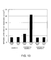
- FIG. 13 is a graph showing diffusion layer contact resistances before and after the cell environment simulation test in Example 9 and Comparative Examples 4 and 5.
- the similar material contact resistance after the cell environment simulation test in Comparative Example 4 increased 14.5 m ⁇ cm 2 beyond the similar material contact resistance before the cell environment simulation test.
- the similar material contact resistance value after the cell environment simulation test in Example 9 increased only 0.2 m ⁇ cm 2 beyond the similar material contact resistance before the cell environment simulation test. This is a value equivalent to that of Comparative Example 5 (a change of 0.1 m ⁇ cm 2 before and after the test).
- the coating layer having the graphite sections is formed on not only the metal substrate but also the porous body, the increase in the contact resistance of the fuel cell separator can be suppressed in the fuel cell power generation environment.
- titanium was used as a target, and a titanium layer (a film thickness 2.5 nm) was formed on a titanium substrate. Then, such a filterless arc ion plating apparatus 3 as shown in FIG. 7 was used to form a coating layer as follows. A carbon material was used as a target 54, arc discharge was effected between the target 54 and an anode 56, and a bias voltage 250 V was applied to a titanium plate as a metal substrate 50, thereby forming an amorphous carbon layer and the coating layer having graphite sections on the titanium layer. This structure was determined as Example 10. Additionally, Examples 11 to 13 are the same as Example 10 except that the film thickness of the titanium layer is 7.5 nm, 25 nm, or 50 nm.
- the coating layer formed on the metal substrate is formed of the amorphous carbon layer and the graphite sections, there can be provided a fuel cell separator that can suppress the corrosion of the metal substrate and inhibit the increase in the contact resistance of the fuel cell separator even in the fuel cell power generation environment.
- the fuel cell separator having the improved adhesion of the coating layer can be obtained.
- setting the film thickness of the titanium layer to 25 nm or above is effective.
- filterless arc ion plating method enables formation of the amorphous carbon layer and the graphite sections in a simple manufacturing process.
- the fuel cell according to the present invention is effective in any application so long as it is an application utilizing the fuel cell, and can be used for, e.g., a small power supply for a mobile device such as a mobile phone or a portable personal computer, a car power supply, or a stationary power supply.
Landscapes
- Chemical & Material Sciences (AREA)
- Life Sciences & Earth Sciences (AREA)
- Engineering & Computer Science (AREA)
- Manufacturing & Machinery (AREA)
- Sustainable Development (AREA)
- Sustainable Energy (AREA)
- Chemical Kinetics & Catalysis (AREA)
- Electrochemistry (AREA)
- General Chemical & Material Sciences (AREA)
- Composite Materials (AREA)
- Fuel Cell (AREA)
Applications Claiming Priority (2)
| Application Number | Priority Date | Filing Date | Title |
|---|---|---|---|
| JP2007041592A JP4702304B2 (ja) | 2007-02-22 | 2007-02-22 | 燃料電池用セパレータ、燃料電池用セパレータの製造方法及び燃料電池 |
| PCT/JP2008/052784 WO2008114561A1 (fr) | 2007-02-22 | 2008-02-12 | Séparateur de pile à combustible, procédé de séparation de pile à combustible et pile à combustible |
Publications (3)
| Publication Number | Publication Date |
|---|---|
| EP2124278A1 true EP2124278A1 (fr) | 2009-11-25 |
| EP2124278A4 EP2124278A4 (fr) | 2011-12-28 |
| EP2124278B1 EP2124278B1 (fr) | 2017-11-08 |
Family
ID=39765675
Family Applications (1)
| Application Number | Title | Priority Date | Filing Date |
|---|---|---|---|
| EP08711595.2A Active EP2124278B1 (fr) | 2007-02-22 | 2008-02-12 | Séparateur de pile à combustible, procédé de séparation de pile à combustible et pile à combustible |
Country Status (7)
| Country | Link |
|---|---|
| US (1) | US8906571B2 (fr) |
| EP (1) | EP2124278B1 (fr) |
| JP (1) | JP4702304B2 (fr) |
| KR (1) | KR101127197B1 (fr) |
| CN (1) | CN101617428B (fr) |
| CA (1) | CA2676704C (fr) |
| WO (1) | WO2008114561A1 (fr) |
Cited By (1)
| Publication number | Priority date | Publication date | Assignee | Title |
|---|---|---|---|---|
| EP2642571A1 (fr) * | 2012-03-23 | 2013-09-25 | Kabushiki Kaisha Kobe Seiko Sho (Kobe Steel, Ltd.) | Matériau séparateur pour pile à combustible, pile à combustible et procédé de fabrication d'un matériau séparateur pour pile à combustible |
Families Citing this family (34)
| Publication number | Priority date | Publication date | Assignee | Title |
|---|---|---|---|---|
| JP5034651B2 (ja) * | 2007-04-24 | 2012-09-26 | トヨタ自動車株式会社 | 非水電解質電池用集電体、非水電解質電池用集電体の製造方法及び非水電解質電池 |
| CN102138238B (zh) * | 2008-06-26 | 2014-04-16 | 新日铁住金株式会社 | 固体高分子型燃料电池的隔板用不锈钢材料以及使用其的固体高分子型燃料电池 |
| JP5261844B2 (ja) * | 2008-08-29 | 2013-08-14 | 株式会社エクォス・リサーチ | 保護基板及び保護基板の製造方法 |
| JP5493341B2 (ja) * | 2008-11-28 | 2014-05-14 | 日産自動車株式会社 | 導電部材、その製造方法、ならびにこれを用いた燃料電池用セパレータおよび固体高分子形燃料電池 |
| TW201035359A (en) * | 2009-03-20 | 2010-10-01 | Univ Feng Chia | Metal material coated with carbon film |
| JP5391855B2 (ja) * | 2009-06-15 | 2014-01-15 | 日産自動車株式会社 | 導電部材、その製造方法、並びにこれを用いた燃料電池用セパレータおよび固体高分子形燃料電池 |
| JP5180932B2 (ja) * | 2009-09-01 | 2013-04-10 | 株式会社神戸製鋼所 | 燃料電池セパレータ用金属含有炭素膜の形成方法および燃料電池セパレータ用耐食皮膜の形成方法 |
| JP2011134653A (ja) * | 2009-12-25 | 2011-07-07 | Toyota Motor Corp | 燃料電池用セパレータ、燃料電池用ガス流路層とこれらの製造方法 |
| KR101242986B1 (ko) * | 2010-03-22 | 2013-03-12 | 현대하이스코 주식회사 | 연료전지용 금속 분리판 제조 방법 |
| JP2012011393A (ja) * | 2010-06-29 | 2012-01-19 | Kobe Steel Ltd | せん断用金型及びその製造方法 |
| JP4886884B2 (ja) | 2010-07-20 | 2012-02-29 | 株式会社神戸製鋼所 | チタン製燃料電池セパレータおよびその製造方法 |
| JP4886885B2 (ja) | 2010-07-20 | 2012-02-29 | 株式会社神戸製鋼所 | チタン製燃料電池セパレータ |
| JP5108976B2 (ja) | 2011-02-14 | 2012-12-26 | 株式会社神戸製鋼所 | 燃料電池セパレータ |
| JP5973790B2 (ja) * | 2012-05-28 | 2016-08-23 | 株式会社中山アモルファス | 耐食性、導電性、成形性に優れた薄板およびその製造方法 |
| JP6122589B2 (ja) | 2012-07-20 | 2017-04-26 | 株式会社神戸製鋼所 | 燃料電池セパレータ |
| WO2014129545A1 (fr) * | 2013-02-22 | 2014-08-28 | 住友電気工業株式会社 | Élément poreux et élément catalyseur |
| JP5890367B2 (ja) * | 2013-09-24 | 2016-03-22 | トヨタ自動車株式会社 | 燃料電池用セパレータ、燃料電池、及び、燃料電池用セパレータの製造方法 |
| JP2016122642A (ja) | 2014-05-28 | 2016-07-07 | 株式会社神戸製鋼所 | 燃料電池用セパレータ材及びその製造方法 |
| JP6083426B2 (ja) * | 2014-11-14 | 2017-02-22 | トヨタ自動車株式会社 | 燃料電池用セパレータ |
| JP6014807B2 (ja) | 2014-11-20 | 2016-10-26 | 株式会社プラズマイオンアシスト | 燃料電池用セパレータ又は燃料電池用集電部材、及びその製造方法 |
| US10276878B2 (en) * | 2016-07-08 | 2019-04-30 | GM Global Technology Operations LLC | Coated aluminum bipolar plate for fuel cell applications |
| CN107681173A (zh) * | 2017-08-03 | 2018-02-09 | 上海交通大学 | 一种用于燃料电池金属极板的点状导电复合涂层 |
| KR102429014B1 (ko) * | 2017-08-16 | 2022-08-03 | 현대자동차 주식회사 | 연료전지용 분리판 및 연료전지용 분리판의 코팅 방법 |
| KR20200096217A (ko) * | 2017-10-24 | 2020-08-11 | 우수이 고쿠사이 산교 가부시키가이샤 | 금속재 및 그 제조 방법 |
| US20210066729A1 (en) * | 2018-02-21 | 2021-03-04 | Nippon Steel Corporation | Titanium material, separator, fuel cell, and fuel cell stack |
| CN109037723B (zh) * | 2018-07-23 | 2022-05-27 | 上海交通大学 | 一种用于燃料电池金属双极板的石墨微晶碳涂层及应用 |
| CN110797545B (zh) * | 2019-10-11 | 2021-02-19 | 浙江锋源氢能科技有限公司 | 一种金属双极板及其制备方法以及燃料电池 |
| CN113067003B (zh) * | 2019-12-14 | 2023-02-28 | 中国科学院大连化学物理研究所 | 一种燃料电池导水板及其制备方法 |
| JP7359124B2 (ja) * | 2020-10-12 | 2023-10-11 | トヨタ自動車株式会社 | 燃料電池用セパレータの製造方法 |
| SE545852C2 (en) * | 2022-01-11 | 2024-02-20 | Smoltek Ab | A separator element with a coating comprising nanostructures |
| KR20230127658A (ko) | 2022-02-25 | 2023-09-01 | 주식회사 세종이브이 | 연료전지용 금속 분리판 |
| KR20230127661A (ko) | 2022-02-25 | 2023-09-01 | 주식회사 세종이브이 | 연료전지 금속 분리판용 탄소막 |
| CN114597436B (zh) * | 2022-03-28 | 2023-06-16 | 中国科学院兰州化学物理研究所 | 一种用于金属双极板的防护涂层及其制备方法 |
| CN114665114A (zh) * | 2022-04-11 | 2022-06-24 | 上海电气集团股份有限公司 | 一种多层复合碳涂层及其制备方法和应用 |
Citations (4)
| Publication number | Priority date | Publication date | Assignee | Title |
|---|---|---|---|---|
| EP1227531A1 (fr) * | 1999-09-02 | 2002-07-31 | Matsushita Electric Industrial Co., Ltd. | Pile a combustible a electrolyte polymere |
| JP2002216786A (ja) * | 2001-01-23 | 2002-08-02 | Hitachi Ltd | 固体高分子型燃料電池 |
| JP2005093172A (ja) * | 2003-09-16 | 2005-04-07 | Nippon Steel Corp | 燃料電池用セパレータおよび燃料電池 |
| WO2007091139A1 (fr) * | 2006-02-10 | 2007-08-16 | Toyota Jidosha Kabushiki Kaisha | Element resistant a l'erosion par cavitation et son procede de fabrication |
Family Cites Families (19)
| Publication number | Priority date | Publication date | Assignee | Title |
|---|---|---|---|---|
| US5389270A (en) * | 1993-05-17 | 1995-02-14 | Electrochemicals, Inc. | Composition and process for preparing a non-conductive substrate for electroplating |
| JP4707786B2 (ja) * | 1998-05-07 | 2011-06-22 | トヨタ自動車株式会社 | 燃料電池用ガスセパレータの製造方法 |
| JP2000164228A (ja) | 1998-11-25 | 2000-06-16 | Toshiba Corp | 固体高分子電解質型燃料電池のセパレータおよびその製造方法 |
| CA2256847A1 (fr) | 1998-12-22 | 2000-06-22 | Munther Kandah | Source ionique exempte de particules pour arc cathodique au carbone |
| BR0008383A (pt) | 1999-07-19 | 2002-04-02 | Sumitomo Electric Industries | Separador para bateria de combustìvel eletrolìtica de polìmero sólido |
| US6864007B1 (en) * | 1999-10-08 | 2005-03-08 | Hybrid Power Generation Systems, Llc | Corrosion resistant coated fuel cell plate with graphite protective barrier and method of making the same |
| JP2001283872A (ja) * | 2000-03-30 | 2001-10-12 | Nisshin Steel Co Ltd | 低温型燃料電池用セパレータ及びその製造方法 |
| JP2001357859A (ja) * | 2000-06-13 | 2001-12-26 | Riken Corp | 燃料電池用セパレータ |
| JP3857873B2 (ja) | 2000-11-09 | 2006-12-13 | 三洋電機株式会社 | 燃料電池用セパレータとその製造方法、および燃料電池 |
| JP4112814B2 (ja) | 2001-03-29 | 2008-07-02 | 株式会社神戸製鋼所 | 靭性に優れた耐摩耗性鉄系皮膜及びその製造方法 |
| JP3498077B2 (ja) | 2001-10-10 | 2004-02-16 | 日本金属工業株式会社 | 固体高分子電解質型燃料電池用セパレータ |
| JP2003331861A (ja) * | 2002-05-16 | 2003-11-21 | Nippon Steel Corp | 燃料電池の低接触抵抗性セパレータ/炭素材料界面構造およびその炭素材料およびセパレータ、ならびに燃料電池用ステンレス鋼製セパレータの製造方法 |
| JP2004014208A (ja) | 2002-06-05 | 2004-01-15 | Toyota Motor Corp | 燃料電池のセパレータとその製造方法 |
| JP4072048B2 (ja) | 2002-12-03 | 2008-04-02 | 住友電工ハードメタル株式会社 | 表面被覆加工用工具 |
| US20050098437A1 (en) | 2003-11-12 | 2005-05-12 | Proton Energy Systems, Inc. | Use of carbon coating in an electrochemical cell |
| JP4904772B2 (ja) | 2004-12-28 | 2012-03-28 | 日立電線株式会社 | 燃料電池用セパレータとその製造方法、および導電性耐食金属材 |
| CN100550489C (zh) | 2005-02-01 | 2009-10-14 | 株式会社新王材料 | 燃料电池用隔板及其制造方法 |
| JP2007157639A (ja) | 2005-12-08 | 2007-06-21 | Toyota Central Res & Dev Lab Inc | 燃料電池用金属セパレータおよびその製造方法 |
| JP2008041390A (ja) | 2006-08-04 | 2008-02-21 | Nissan Motor Co Ltd | 燃料電池および燃料電池の導電性セパレータの製造方法 |
-
2007
- 2007-02-22 JP JP2007041592A patent/JP4702304B2/ja active Active
-
2008
- 2008-02-12 CN CN2008800056387A patent/CN101617428B/zh active Active
- 2008-02-12 EP EP08711595.2A patent/EP2124278B1/fr active Active
- 2008-02-12 CA CA2676704A patent/CA2676704C/fr active Active
- 2008-02-12 US US12/527,989 patent/US8906571B2/en active Active
- 2008-02-12 KR KR1020097019656A patent/KR101127197B1/ko active IP Right Grant
- 2008-02-12 WO PCT/JP2008/052784 patent/WO2008114561A1/fr active Application Filing
Patent Citations (4)
| Publication number | Priority date | Publication date | Assignee | Title |
|---|---|---|---|---|
| EP1227531A1 (fr) * | 1999-09-02 | 2002-07-31 | Matsushita Electric Industrial Co., Ltd. | Pile a combustible a electrolyte polymere |
| JP2002216786A (ja) * | 2001-01-23 | 2002-08-02 | Hitachi Ltd | 固体高分子型燃料電池 |
| JP2005093172A (ja) * | 2003-09-16 | 2005-04-07 | Nippon Steel Corp | 燃料電池用セパレータおよび燃料電池 |
| WO2007091139A1 (fr) * | 2006-02-10 | 2007-08-16 | Toyota Jidosha Kabushiki Kaisha | Element resistant a l'erosion par cavitation et son procede de fabrication |
Non-Patent Citations (1)
| Title |
|---|
| See also references of WO2008114561A1 * |
Cited By (1)
| Publication number | Priority date | Publication date | Assignee | Title |
|---|---|---|---|---|
| EP2642571A1 (fr) * | 2012-03-23 | 2013-09-25 | Kabushiki Kaisha Kobe Seiko Sho (Kobe Steel, Ltd.) | Matériau séparateur pour pile à combustible, pile à combustible et procédé de fabrication d'un matériau séparateur pour pile à combustible |
Also Published As
| Publication number | Publication date |
|---|---|
| EP2124278A4 (fr) | 2011-12-28 |
| US20100035120A1 (en) | 2010-02-11 |
| KR20090121352A (ko) | 2009-11-25 |
| JP4702304B2 (ja) | 2011-06-15 |
| EP2124278B1 (fr) | 2017-11-08 |
| JP2008204876A (ja) | 2008-09-04 |
| CN101617428B (zh) | 2012-07-18 |
| KR101127197B1 (ko) | 2012-03-29 |
| WO2008114561A1 (fr) | 2008-09-25 |
| CN101617428A (zh) | 2009-12-30 |
| US8906571B2 (en) | 2014-12-09 |
| CA2676704C (fr) | 2012-12-18 |
| CA2676704A1 (fr) | 2008-09-25 |
Similar Documents
| Publication | Publication Date | Title |
|---|---|---|
| CA2676704C (fr) | Separateur de pile a combustible, procede de separation de pile a combustible et pile a combustible | |
| EP2817430B1 (fr) | Revêtement présentant des caractéristiques de conduction et de résistance à la corrosion | |
| Barranco et al. | Cr and Zr/Cr nitride CAE-PVD coated aluminum bipolar plates for polymer electrolyte membrane fuel cells | |
| EP2157645B1 (fr) | Séparateur métallique pour pile à combustible et procédé pour sa fabrication | |
| EP2369668B1 (fr) | Séparateur métallique pour pile à combustible et procédé de fabrication associé | |
| US10516174B2 (en) | Metal sheet for separators of polymer electrolyte fuel cells, and metal sheet for manufacturing the same | |
| JP5391855B2 (ja) | 導電部材、その製造方法、並びにこれを用いた燃料電池用セパレータおよび固体高分子形燃料電池 | |
| EP2597710A1 (fr) | Séparateur de pile à combustible au titane | |
| Li et al. | Investigation of single-layer and multilayer coatings for aluminum bipolar plate in polymer electrolyte membrane fuel cell | |
| JP4926730B2 (ja) | 固体高分子型燃料電池セパレーター用チタン材およびその製造方法、このチタン材を用いてなるセパレーター、ならびにこのセパレーターを用いてなる固体高分子型燃料電池 | |
| US9793554B2 (en) | Fuel cell separator and fuel cell | |
| EP3285319B1 (fr) | Plaque métallique destinée à être utilisée comme séparateur de pile à combustible à polymère solide | |
| JP5192908B2 (ja) | 燃料電池セパレータ用チタン基材、および、燃料電池セパレータ、ならびに燃料電池セパレータの製造方法 | |
| JP2007165275A (ja) | セパレータ、それを用いた固体高分子型燃料電池およびそのセパレータの製造方法 | |
| JP2005093172A (ja) | 燃料電池用セパレータおよび燃料電池 | |
| JP5439965B2 (ja) | 導電部材、その製造方法、並びにこれを用いた燃料電池用セパレータおよび固体高分子形燃料電池 | |
| JP2010272490A (ja) | 燃料電池構成部品用表面処理部材ならびにその製造方法 | |
| Fan et al. | Solution acidity and temperature induced anodic dissolution and degradation of through-plane electrical conductivity of Au/TiN coated metal bipolar plates used in PEMFC | |
| JP5272575B2 (ja) | 燃料電池用セパレータの製造方法 | |
| JP7484760B2 (ja) | セパレータの製造方法 | |
| JP5397725B2 (ja) | 燃料電池用導電部材 | |
| JP2011249148A (ja) | 燃料電池用セパレータ材料、それを用いた燃料電池用セパレータ及び燃料電池スタック、並びに燃料電池用セパレータ材料の製造方法 | |
| JP2011243473A (ja) | 燃料電池用セパレータ材料、それを用いた燃料電池用セパレータ及び燃料電池スタック、並びに燃料電池用セパレータ材料の製造方法 | |
| JP2011249147A (ja) | 燃料電池用セパレータ材料、それを用いた燃料電池用セパレータ及び燃料電池スタック、並びに燃料電池用セパレータ材料の製造方法 |
Legal Events
| Date | Code | Title | Description |
|---|---|---|---|
| PUAI | Public reference made under article 153(3) epc to a published international application that has entered the european phase |
Free format text: ORIGINAL CODE: 0009012 |
|
| 17P | Request for examination filed |
Effective date: 20090922 |
|
| AK | Designated contracting states |
Kind code of ref document: A1 Designated state(s): AT BE BG CH CY CZ DE DK EE ES FI FR GB GR HR HU IE IS IT LI LT LU LV MC MT NL NO PL PT RO SE SI SK TR |
|
| DAX | Request for extension of the european patent (deleted) | ||
| A4 | Supplementary search report drawn up and despatched |
Effective date: 20111124 |
|
| RIC1 | Information provided on ipc code assigned before grant |
Ipc: H01M 8/02 20060101AFI20111118BHEP |
|
| RAP1 | Party data changed (applicant data changed or rights of an application transferred) |
Owner name: TOYOTA JIDOSHA KABUSHIKI KAISHA |
|
| 17Q | First examination report despatched |
Effective date: 20140207 |
|
| REG | Reference to a national code |
Ref country code: DE Ref legal event code: R079 Ref document number: 602008052850 Country of ref document: DE Free format text: PREVIOUS MAIN CLASS: H01M0008020000 Ipc: H01M0008022800 |
|
| RIC1 | Information provided on ipc code assigned before grant |
Ipc: H01M 8/0228 20160101AFI20170421BHEP Ipc: H01M 8/0213 20160101ALI20170421BHEP Ipc: H01M 8/0206 20160101ALI20170421BHEP Ipc: H01M 8/0226 20160101ALI20170421BHEP |
|
| GRAP | Despatch of communication of intention to grant a patent |
Free format text: ORIGINAL CODE: EPIDOSNIGR1 |
|
| INTG | Intention to grant announced |
Effective date: 20170608 |
|
| GRAS | Grant fee paid |
Free format text: ORIGINAL CODE: EPIDOSNIGR3 |
|
| GRAA | (expected) grant |
Free format text: ORIGINAL CODE: 0009210 |
|
| AK | Designated contracting states |
Kind code of ref document: B1 Designated state(s): AT BE BG CH CY CZ DE DK EE ES FI FR GB GR HR HU IE IS IT LI LT LU LV MC MT NL NO PL PT RO SE SI SK TR |
|
| REG | Reference to a national code |
Ref country code: GB Ref legal event code: FG4D |
|
| REG | Reference to a national code |
Ref country code: CH Ref legal event code: EP Ref country code: AT Ref legal event code: REF Ref document number: 944966 Country of ref document: AT Kind code of ref document: T Effective date: 20171115 |
|
| REG | Reference to a national code |
Ref country code: IE Ref legal event code: FG4D |
|
| REG | Reference to a national code |
Ref country code: DE Ref legal event code: R096 Ref document number: 602008052850 Country of ref document: DE |
|
| REG | Reference to a national code |
Ref country code: FR Ref legal event code: PLFP Year of fee payment: 11 |
|
| REG | Reference to a national code |
Ref country code: NL Ref legal event code: MP Effective date: 20171108 |
|
| REG | Reference to a national code |
Ref country code: LT Ref legal event code: MG4D |
|
| REG | Reference to a national code |
Ref country code: AT Ref legal event code: MK05 Ref document number: 944966 Country of ref document: AT Kind code of ref document: T Effective date: 20171108 |
|
| PG25 | Lapsed in a contracting state [announced via postgrant information from national office to epo] |
Ref country code: FI Free format text: LAPSE BECAUSE OF FAILURE TO SUBMIT A TRANSLATION OF THE DESCRIPTION OR TO PAY THE FEE WITHIN THE PRESCRIBED TIME-LIMIT Effective date: 20171108 Ref country code: NO Free format text: LAPSE BECAUSE OF FAILURE TO SUBMIT A TRANSLATION OF THE DESCRIPTION OR TO PAY THE FEE WITHIN THE PRESCRIBED TIME-LIMIT Effective date: 20180208 Ref country code: NL Free format text: LAPSE BECAUSE OF FAILURE TO SUBMIT A TRANSLATION OF THE DESCRIPTION OR TO PAY THE FEE WITHIN THE PRESCRIBED TIME-LIMIT Effective date: 20171108 Ref country code: ES Free format text: LAPSE BECAUSE OF FAILURE TO SUBMIT A TRANSLATION OF THE DESCRIPTION OR TO PAY THE FEE WITHIN THE PRESCRIBED TIME-LIMIT Effective date: 20171108 Ref country code: SE Free format text: LAPSE BECAUSE OF FAILURE TO SUBMIT A TRANSLATION OF THE DESCRIPTION OR TO PAY THE FEE WITHIN THE PRESCRIBED TIME-LIMIT Effective date: 20171108 Ref country code: LT Free format text: LAPSE BECAUSE OF FAILURE TO SUBMIT A TRANSLATION OF THE DESCRIPTION OR TO PAY THE FEE WITHIN THE PRESCRIBED TIME-LIMIT Effective date: 20171108 |
|
| PG25 | Lapsed in a contracting state [announced via postgrant information from national office to epo] |
Ref country code: IS Free format text: LAPSE BECAUSE OF FAILURE TO SUBMIT A TRANSLATION OF THE DESCRIPTION OR TO PAY THE FEE WITHIN THE PRESCRIBED TIME-LIMIT Effective date: 20180308 Ref country code: BG Free format text: LAPSE BECAUSE OF FAILURE TO SUBMIT A TRANSLATION OF THE DESCRIPTION OR TO PAY THE FEE WITHIN THE PRESCRIBED TIME-LIMIT Effective date: 20180208 Ref country code: LV Free format text: LAPSE BECAUSE OF FAILURE TO SUBMIT A TRANSLATION OF THE DESCRIPTION OR TO PAY THE FEE WITHIN THE PRESCRIBED TIME-LIMIT Effective date: 20171108 Ref country code: AT Free format text: LAPSE BECAUSE OF FAILURE TO SUBMIT A TRANSLATION OF THE DESCRIPTION OR TO PAY THE FEE WITHIN THE PRESCRIBED TIME-LIMIT Effective date: 20171108 Ref country code: GR Free format text: LAPSE BECAUSE OF FAILURE TO SUBMIT A TRANSLATION OF THE DESCRIPTION OR TO PAY THE FEE WITHIN THE PRESCRIBED TIME-LIMIT Effective date: 20180209 Ref country code: HR Free format text: LAPSE BECAUSE OF FAILURE TO SUBMIT A TRANSLATION OF THE DESCRIPTION OR TO PAY THE FEE WITHIN THE PRESCRIBED TIME-LIMIT Effective date: 20171108 |
|
| PG25 | Lapsed in a contracting state [announced via postgrant information from national office to epo] |
Ref country code: DK Free format text: LAPSE BECAUSE OF FAILURE TO SUBMIT A TRANSLATION OF THE DESCRIPTION OR TO PAY THE FEE WITHIN THE PRESCRIBED TIME-LIMIT Effective date: 20171108 Ref country code: EE Free format text: LAPSE BECAUSE OF FAILURE TO SUBMIT A TRANSLATION OF THE DESCRIPTION OR TO PAY THE FEE WITHIN THE PRESCRIBED TIME-LIMIT Effective date: 20171108 Ref country code: CY Free format text: LAPSE BECAUSE OF FAILURE TO SUBMIT A TRANSLATION OF THE DESCRIPTION OR TO PAY THE FEE WITHIN THE PRESCRIBED TIME-LIMIT Effective date: 20171108 Ref country code: SK Free format text: LAPSE BECAUSE OF FAILURE TO SUBMIT A TRANSLATION OF THE DESCRIPTION OR TO PAY THE FEE WITHIN THE PRESCRIBED TIME-LIMIT Effective date: 20171108 Ref country code: CZ Free format text: LAPSE BECAUSE OF FAILURE TO SUBMIT A TRANSLATION OF THE DESCRIPTION OR TO PAY THE FEE WITHIN THE PRESCRIBED TIME-LIMIT Effective date: 20171108 |
|
| REG | Reference to a national code |
Ref country code: DE Ref legal event code: R097 Ref document number: 602008052850 Country of ref document: DE |
|
| PG25 | Lapsed in a contracting state [announced via postgrant information from national office to epo] |
Ref country code: RO Free format text: LAPSE BECAUSE OF FAILURE TO SUBMIT A TRANSLATION OF THE DESCRIPTION OR TO PAY THE FEE WITHIN THE PRESCRIBED TIME-LIMIT Effective date: 20171108 Ref country code: PL Free format text: LAPSE BECAUSE OF FAILURE TO SUBMIT A TRANSLATION OF THE DESCRIPTION OR TO PAY THE FEE WITHIN THE PRESCRIBED TIME-LIMIT Effective date: 20171108 |
|
| PLBE | No opposition filed within time limit |
Free format text: ORIGINAL CODE: 0009261 |
|
| REG | Reference to a national code |
Ref country code: CH Ref legal event code: PL |
|
| STAA | Information on the status of an ep patent application or granted ep patent |
Free format text: STATUS: NO OPPOSITION FILED WITHIN TIME LIMIT |
|
| PG25 | Lapsed in a contracting state [announced via postgrant information from national office to epo] |
Ref country code: MC Free format text: LAPSE BECAUSE OF FAILURE TO SUBMIT A TRANSLATION OF THE DESCRIPTION OR TO PAY THE FEE WITHIN THE PRESCRIBED TIME-LIMIT Effective date: 20171108 |
|
| REG | Reference to a national code |
Ref country code: DE Ref legal event code: R084 Ref document number: 602008052850 Country of ref document: DE |
|
| 26N | No opposition filed |
Effective date: 20180809 |
|
| GBPC | Gb: european patent ceased through non-payment of renewal fee |
Effective date: 20180212 |
|
| REG | Reference to a national code |
Ref country code: IE Ref legal event code: MM4A |
|
| REG | Reference to a national code |
Ref country code: BE Ref legal event code: MM Effective date: 20180228 |
|
| PG25 | Lapsed in a contracting state [announced via postgrant information from national office to epo] |
Ref country code: CH Free format text: LAPSE BECAUSE OF NON-PAYMENT OF DUE FEES Effective date: 20180228 Ref country code: LI Free format text: LAPSE BECAUSE OF NON-PAYMENT OF DUE FEES Effective date: 20180228 Ref country code: LU Free format text: LAPSE BECAUSE OF NON-PAYMENT OF DUE FEES Effective date: 20180212 Ref country code: SI Free format text: LAPSE BECAUSE OF FAILURE TO SUBMIT A TRANSLATION OF THE DESCRIPTION OR TO PAY THE FEE WITHIN THE PRESCRIBED TIME-LIMIT Effective date: 20171108 |
|
| PG25 | Lapsed in a contracting state [announced via postgrant information from national office to epo] |
Ref country code: IE Free format text: LAPSE BECAUSE OF NON-PAYMENT OF DUE FEES Effective date: 20180212 |
|
| PG25 | Lapsed in a contracting state [announced via postgrant information from national office to epo] |
Ref country code: GB Free format text: LAPSE BECAUSE OF NON-PAYMENT OF DUE FEES Effective date: 20180212 Ref country code: BE Free format text: LAPSE BECAUSE OF NON-PAYMENT OF DUE FEES Effective date: 20180228 |
|
| PG25 | Lapsed in a contracting state [announced via postgrant information from national office to epo] |
Ref country code: MT Free format text: LAPSE BECAUSE OF NON-PAYMENT OF DUE FEES Effective date: 20180212 |
|
| PG25 | Lapsed in a contracting state [announced via postgrant information from national office to epo] |
Ref country code: TR Free format text: LAPSE BECAUSE OF FAILURE TO SUBMIT A TRANSLATION OF THE DESCRIPTION OR TO PAY THE FEE WITHIN THE PRESCRIBED TIME-LIMIT Effective date: 20171108 |
|
| PG25 | Lapsed in a contracting state [announced via postgrant information from national office to epo] |
Ref country code: HU Free format text: LAPSE BECAUSE OF FAILURE TO SUBMIT A TRANSLATION OF THE DESCRIPTION OR TO PAY THE FEE WITHIN THE PRESCRIBED TIME-LIMIT; INVALID AB INITIO Effective date: 20080212 Ref country code: PT Free format text: LAPSE BECAUSE OF FAILURE TO SUBMIT A TRANSLATION OF THE DESCRIPTION OR TO PAY THE FEE WITHIN THE PRESCRIBED TIME-LIMIT Effective date: 20171108 |
|
| PGFP | Annual fee paid to national office [announced via postgrant information from national office to epo] |
Ref country code: IT Payment date: 20220111 Year of fee payment: 15 Ref country code: FR Payment date: 20220118 Year of fee payment: 15 |
|
| P01 | Opt-out of the competence of the unified patent court (upc) registered |
Effective date: 20230427 |
|
| PG25 | Lapsed in a contracting state [announced via postgrant information from national office to epo] |
Ref country code: IT Free format text: LAPSE BECAUSE OF NON-PAYMENT OF DUE FEES Effective date: 20230212 Ref country code: FR Free format text: LAPSE BECAUSE OF NON-PAYMENT OF DUE FEES Effective date: 20230228 |
|
| PGFP | Annual fee paid to national office [announced via postgrant information from national office to epo] |
Ref country code: DE Payment date: 20231228 Year of fee payment: 17 |