EP2090874B1 - Einrichtung zur detektion des schwerpunkts, einrichtung zur vorhersage der kritischen geschwindigkeit für laterales umkippen und einrichtung zur vorhersage von frachtgewicht - Google Patents
Einrichtung zur detektion des schwerpunkts, einrichtung zur vorhersage der kritischen geschwindigkeit für laterales umkippen und einrichtung zur vorhersage von frachtgewicht Download PDFInfo
- Publication number
- EP2090874B1 EP2090874B1 EP07832388.8A EP07832388A EP2090874B1 EP 2090874 B1 EP2090874 B1 EP 2090874B1 EP 07832388 A EP07832388 A EP 07832388A EP 2090874 B1 EP2090874 B1 EP 2090874B1
- Authority
- EP
- European Patent Office
- Prior art keywords
- container
- center
- gravity
- vehicle
- cargo
- Prior art date
- Legal status (The legal status is an assumption and is not a legal conclusion. Google has not performed a legal analysis and makes no representation as to the accuracy of the status listed.)
- Active
Links
- 230000005484 gravity Effects 0.000 title claims description 243
- 230000033001 locomotion Effects 0.000 claims description 113
- 230000014509 gene expression Effects 0.000 claims description 104
- 238000005096 rolling process Methods 0.000 claims description 80
- 238000001514 detection method Methods 0.000 claims description 77
- 230000004044 response Effects 0.000 claims description 11
- 230000002123 temporal effect Effects 0.000 claims description 9
- 230000008878 coupling Effects 0.000 claims description 8
- 238000010168 coupling process Methods 0.000 claims description 8
- 238000005859 coupling reaction Methods 0.000 claims description 8
- 238000000034 method Methods 0.000 description 89
- 238000003860 storage Methods 0.000 description 49
- 238000012795 verification Methods 0.000 description 45
- 238000002474 experimental method Methods 0.000 description 38
- 238000005259 measurement Methods 0.000 description 36
- 238000009826 distribution Methods 0.000 description 28
- 238000005516 engineering process Methods 0.000 description 22
- 239000000725 suspension Substances 0.000 description 21
- 230000008859 change Effects 0.000 description 18
- 238000010586 diagram Methods 0.000 description 15
- 230000001133 acceleration Effects 0.000 description 14
- 239000000203 mixture Substances 0.000 description 11
- 238000009472 formulation Methods 0.000 description 9
- 238000012545 processing Methods 0.000 description 9
- 238000006243 chemical reaction Methods 0.000 description 8
- 238000012937 correction Methods 0.000 description 8
- 238000009795 derivation Methods 0.000 description 8
- 229920000535 Tan II Polymers 0.000 description 7
- 238000004364 calculation method Methods 0.000 description 6
- 238000007796 conventional method Methods 0.000 description 6
- 230000032683 aging Effects 0.000 description 5
- 230000006870 function Effects 0.000 description 5
- 230000009471 action Effects 0.000 description 4
- 230000006399 behavior Effects 0.000 description 4
- 230000008901 benefit Effects 0.000 description 4
- 238000004891 communication Methods 0.000 description 4
- 238000000605 extraction Methods 0.000 description 4
- 238000007689 inspection Methods 0.000 description 4
- 238000012360 testing method Methods 0.000 description 4
- 230000002159 abnormal effect Effects 0.000 description 3
- 238000010420 art technique Methods 0.000 description 3
- 230000000694 effects Effects 0.000 description 3
- 230000008676 import Effects 0.000 description 3
- 238000004519 manufacturing process Methods 0.000 description 3
- 239000000463 material Substances 0.000 description 3
- 238000005070 sampling Methods 0.000 description 3
- 239000000853 adhesive Substances 0.000 description 2
- 230000001070 adhesive effect Effects 0.000 description 2
- 238000004458 analytical method Methods 0.000 description 2
- 238000013459 approach Methods 0.000 description 2
- 230000001174 ascending effect Effects 0.000 description 2
- 230000033228 biological regulation Effects 0.000 description 2
- 239000004973 liquid crystal related substance Substances 0.000 description 2
- 239000011159 matrix material Substances 0.000 description 2
- 230000010355 oscillation Effects 0.000 description 2
- 230000008569 process Effects 0.000 description 2
- 230000005856 abnormality Effects 0.000 description 1
- 230000005540 biological transmission Effects 0.000 description 1
- 230000003139 buffering effect Effects 0.000 description 1
- 238000010276 construction Methods 0.000 description 1
- 230000010485 coping Effects 0.000 description 1
- 239000013078 crystal Substances 0.000 description 1
- 230000007423 decrease Effects 0.000 description 1
- 230000001419 dependent effect Effects 0.000 description 1
- 238000011161 development Methods 0.000 description 1
- 230000018109 developmental process Effects 0.000 description 1
- 230000003292 diminished effect Effects 0.000 description 1
- 238000006073 displacement reaction Methods 0.000 description 1
- 230000008030 elimination Effects 0.000 description 1
- 238000003379 elimination reaction Methods 0.000 description 1
- 230000006698 induction Effects 0.000 description 1
- 238000012986 modification Methods 0.000 description 1
- 230000004048 modification Effects 0.000 description 1
- 230000007935 neutral effect Effects 0.000 description 1
- 230000002265 prevention Effects 0.000 description 1
- 230000008521 reorganization Effects 0.000 description 1
- 239000004576 sand Substances 0.000 description 1
- 230000003068 static effect Effects 0.000 description 1
- 238000006467 substitution reaction Methods 0.000 description 1
Images


Classifications
-
- B—PERFORMING OPERATIONS; TRANSPORTING
- B60—VEHICLES IN GENERAL
- B60W—CONJOINT CONTROL OF VEHICLE SUB-UNITS OF DIFFERENT TYPE OR DIFFERENT FUNCTION; CONTROL SYSTEMS SPECIALLY ADAPTED FOR HYBRID VEHICLES; ROAD VEHICLE DRIVE CONTROL SYSTEMS FOR PURPOSES NOT RELATED TO THE CONTROL OF A PARTICULAR SUB-UNIT
- B60W40/00—Estimation or calculation of non-directly measurable driving parameters for road vehicle drive control systems not related to the control of a particular sub unit, e.g. by using mathematical models
- B60W40/12—Estimation or calculation of non-directly measurable driving parameters for road vehicle drive control systems not related to the control of a particular sub unit, e.g. by using mathematical models related to parameters of the vehicle itself, e.g. tyre models
-
- G—PHYSICS
- G01—MEASURING; TESTING
- G01G—WEIGHING
- G01G19/00—Weighing apparatus or methods adapted for special purposes not provided for in the preceding groups
- G01G19/08—Weighing apparatus or methods adapted for special purposes not provided for in the preceding groups for incorporation in vehicles
- G01G19/086—Weighing apparatus or methods adapted for special purposes not provided for in the preceding groups for incorporation in vehicles wherein the vehicle mass is dynamically estimated
-
- G—PHYSICS
- G01—MEASURING; TESTING
- G01G—WEIGHING
- G01G23/00—Auxiliary devices for weighing apparatus
- G01G23/18—Indicating devices, e.g. for remote indication; Recording devices; Scales, e.g. graduated
- G01G23/36—Indicating the weight by electrical means, e.g. using photoelectric cells
- G01G23/37—Indicating the weight by electrical means, e.g. using photoelectric cells involving digital counting
- G01G23/3728—Indicating the weight by electrical means, e.g. using photoelectric cells involving digital counting with wireless means
-
- G—PHYSICS
- G01—MEASURING; TESTING
- G01M—TESTING STATIC OR DYNAMIC BALANCE OF MACHINES OR STRUCTURES; TESTING OF STRUCTURES OR APPARATUS, NOT OTHERWISE PROVIDED FOR
- G01M1/00—Testing static or dynamic balance of machines or structures
- G01M1/12—Static balancing; Determining position of centre of gravity
- G01M1/122—Determining position of centre of gravity
Definitions
- the present invention relates to center-of-gravity detection systems and lateral rollover limit velocity estimation systems, and cargo weight estimation systems for vehicles capable of carrying cargo and adapted to be towed by towing vehicles. More particularly, this invention relates to technologies for finding the location of the center of gravity in three-dimensional space of a container cargo vehicle towed and transported by a towing vehicle, for finding the lateral rollover limit velocity of such a vehicle on a curved road section of a road by means of the location of the center of gravity in three-dimensional space, and for finding the weight of cargo.
- container cargo commercially traded in international imports and exports, is placed, together with the container, on a carriage called a container chassis in the domestic distribution network.
- the container chassis is towed and transported by a towing vehicle such as a tractor, railroad engine or the like capable of towing the container chassis.
- container cargo is generally transported without having checked its condition of loading in the container and, as a result, various inconveniences caused by container transport vehicles have been heretofore viewed as social issues.
- situations resulting from the biased loading of cargo in the container e.g., cargo pile collapse/cargo falling occurring when the container door is opened and unstable travel motions of the container transport vehicle when travelling along a curved road section
- social problems are becoming social problems.
- Patent Document 1 there is proposed a conventional technique which is directed to a braking method for a trailer (which corresponds to the container chassis) having a computerized braking system (brake control system) (see Patent Document 1).
- vehicle rollover on a narrow curved road section or at an automobile expressway exit may be prevented.
- WO 98/25779 describes a system which detects the position of the center of gravity with respect to a cross-section surface perpendicular to the travel direction of said container analysing the pendulum "roll” oscillation.
- the 3D center-of-gravity location of the container cargo vehicle serves as valuable data that directly reflects the degree of biasing of the load of the container cargo, and therefore, if such data is found accurately, this will contribute to preventing the cargo from pile collapse/falling when the container door is opened and the container transport vehicle from unstable travel motion along the curved road section.
- the 3D center-of-gravity location of the container cargo vehicle is found accurately, this makes it possible to perform arithmetic to properly estimate the lateral rollover limit velocity of the container cargo vehicle in response to the curvature radius of a curved road section along which the container cargo vehicle travels.
- this makes it possible to perform arithmetic to properly estimate the weight of container cargo, thereby resulting in making it possible to estimate whether the container cargo is overloaded or not.
- container cargo vehicle is a section of the container transport vehicle, excluding its towing vehicle, in other words the container cargo vehicle means a vehicle that is made up of a container capable of carrying cargo and a container chassis (carriage) on which the container is placed.
- the inventor of the present application also succeeded in finding, by means of the 3D center-of-gravity location of a vehicle (for example, the aforesaid container cargo vehicle) which is towed by a towing vehicle, a method of deriving the lateral rollover limit velocity of the vehicle. Furthermore, the inventor of the present application also succeeded in finding, by means of the 3D center-of-gravity location of a vehicle (for example, the aforesaid container cargo vehicle) which is towed by a towing vehicle, a method of deriving the weight of cargo. These derivation methods will be explained later in detail.
- a first aspect of the present invention is intended to provide a center-of-gravity detection system configured to properly derive the 3D center-of-gravity location of a vehicle capable of carrying cargo and adapted to be towed by a towing vehicle (First Problem).
- a second aspect of the present invention is intended to provide a lateral rollover limit velocity estimation system configured to properly derive, by means of the 3D center-of-gravity location of a vehicle capable of carrying cargo and adapted to be towed by a towing vehicle, the lateral rollover limit velocity of the vehicle in response to the curvature radius of a curved road section along which the vehicle travels (Second Problem).
- a third aspect of the present invention is intended to provide a cargo weight estimation system configured to properly derive, by means of the 3D center-of-gravity location of a vehicle capable of carrying cargo and adapted to be towed by a towing vehicle, the weight of the cargo (Third Problem).
- the first aspect of the present invention provides a center-of-gravity detection system according to claim 1.
- a container cargo vehicle comprising a container capable of carrying the cargo and a container chassis on which the container is placed.
- the 3D center-of-gravity location of the container cargo vehicle serves as valuable data that directly reflects the degree of biasing of the load of the container cargo whose condition of loading is unknown, and for example, by means of this, it becomes possible to contribute to preventing the cargo from pile collapse/falling when the container door is opened and the the container transport vehicle from unstable travel motion on the curved road section.
- the 3D center-of-gravity location of the vehicle is derived based upon the logical theory of dynamics, without having to introduce data that lack theoretical ground (e.g., correction coefficient or the like) and, as a result, the reliability of the arithmetic results is extremely high.
- the inventor of the present application took the motion of a vehicle (here, a container cargo vehicle is taken as an example) as a problem of the mechanics of mass point in which the center of gravity of the container cargo vehicle is a mass point. And, this resulted in leading the inventor of the present application to find that the equations of motion that rule the motion of the center of gravity of the container cargo vehicle can be reorganized to a considerably useful mathematical expression in the light of the actual conditions of the container transport operation.
- the first aspect of the present invention is an invention that was devised based upon the foregoing knowledge.
- the physical quantities that correlate with the shakes include the frequency of the reciprocation motion, the frequency of the simple pendulum motion, and the central angle of the simple pendulum motion
- the arithmetic unit is configured to derive, based upon the frequency of the simple pendulum motion, the location of the center of gravity of the container cargo vehicle with respect to the travel direction of the container and to derive, based upon the frequency of the reciprocation motion, the frequency of the simple pendulum motion, and the central angle of the simple pendulum motion, the location of the center of gravity of the container
- the aforesaid physical quantities include neither the elastic coefficient of the container transport vehicle nor the weight of the container cargo vehicle.
- This therefore makes it possible to not only save thousands of man-hours taken to measure elastic coefficient and weight, but also to facilitate the universal application of the present technology to any type of container transport vehicle (that is, any combinations of an indefinite number of towing vehicles, an indefinite number of container chassis, and an indefinite number of containers), regardless of the uncertain factors (e.g., container transport vehicle's manufacturer, model year, degree of aging et cetera).
- the center-of-gravity detection system of the first aspect of the present invention may be a center-of-gravity detection system in which: there is provided a disc-shaped coupling member configured to connect, at between the proximity of a front section of the container chassis relative to the travel direction thereof and the towing vehicle, the both together in a widthwisely swing-movable manner; the container chassis includes a cross beam which extends in the width direction of the container and supports the proximity of a rear section of the container relative to the travel direction thereof; the arithmetic unit is configured to convert output data of the shake detector into rolling data representative of a correlation between the frequency and the amplitude of the simple pendulum motion and to obtain, based upon the rolling data, a first frequency of the simple pendulum motion corresponding to the peak amplitude of the simple pendulum motion originated from the cross beam, a second frequency of the simple pendulum motion corresponding to the peak amplitude of the simple pendulum motion originated from the coupling member, and a third frequency of the simple pendulum motion
- the arithmetic unit may be an arithmetic unit in which: the arithmetic unit is configured to convert output data of the shake detector into rolling data representative of a correlation between the frequency and the amplitude of the simple pendulum motion and to obtain, based upon the rolling data, the frequency of the simple pendulum motion corresponding to the peak amplitude of the simple pendulum motion originated from the center of gravity of the container cargo vehicle; the arithmetic unit is configured to convert output data of the shake detector into pitching data representative of a correlation between the frequency and the amplitude of the reciprocation motion and to obtain, based upon the pitching data, the frequency of the reciprocation motion corresponding to the maximum amplitude of the reciprocation motion; the arithmetic unit is configured to sample temporal data of the amplitude of the simple pendulum motion from output data of the shake detector and to obtain the average value of the temporal data as the central angle of the simple pendulum motion; and based upon the frequency of the simple pendulum motion, the frequency of the frequency of
- the shakes in the vertical (self-weight) and width directions of the container cargo vehicle may be motions resulting from external disturbances imparted, during straight travel of the container cargo vehicle on a road surface, to the container cargo vehicle in response to irregularities of the road surface.
- the center-of-gravity detection system makes it possible for the center-of-gravity detection system to perform arithmetic to calculate the 3D center-of-gravity location of the container cargo vehicle if the container cargo vehicle is made to discretionarily travel to the general flow of traffic (preferably, straight travel). Therefore, the work of obtaining arithmetic data can be conducted easily, which is preferable because there is no need to obtain data at the time of travel along the curved road section.
- the shake detector includes an angular velocity sensor which is mounted in the towing vehicle and whose angular velocity sensitive axes are aligned in the self-weight and width directions of the container cargo vehicle.
- a lateral rollover limit velocity estimation system including a vehicle capable of carrying cargo and adapted to be towed by a towing vehicle and an arithmetic unit in which system the arithmetic unit is configured to obtain the location of the center of gravity, in three-dimensional space, of the towed vehicle and the curvature radius of a curved road section along which the towed vehicle travels and to derive a lateral rollover limit velocity for the curved road section in response to the obtained curvature radius with the use of the obtained location of the center of gravity.
- the center-of-gravity detection system is employed as a concrete method for the arithmetic unit to obtain the center of gravity location, in three-dimensional space, of the vehicle but this is not considered limitative.
- the arithmetic unit is able to obtain the 3D center-of-gravity location by entry of the center-of-gravity location made by the operator.
- Such a lateral rollover limit velocity is a reference velocity as to whether or not the vehicle is brought into lateral rollover, and this makes it possible to contribute to preventing the vehicle from unstable travel motion on the curved road section.
- the arithmetic unit is configured to derive the lateral rollover limit velocity on the basis of: a first expression which represents, by means of the center-of-gravity location of the towed vehicle relative to a cross-section surface perpendicular to the travel direction of the towed vehicle, a relationship between the velocity of the towed vehicle and the curvature radius in the event that the towed vehicle is brought into rotation centered on a turning outer wheel of the towed vehicle; and a second expression which represents, by means of the center-of-gravity location of the towed vehicle relative to the travel direction of the towed vehicle, a relationship between the velocity of the towed vehicle and the curvature radius in the event that the towed vehicle is brought into rotation centered on a point of connection between the towing vehicle and the towed vehicle.
- One example of the towed vehicle is a container cargo vehicle comprising a container capable of carrying the cargo and a container chassis on which the container is placed.
- a shake detector configured to detect shakes in the directions of the self-weight and width of the towed vehicle during travel of the towed vehicle, and that based upon physical quantities that correlate with the shakes, the arithmetic unit is configured to derive the location of the center of gravity.
- This arrangement makes it possible to perform arithmetic to calculate various types of center-of-gravity related data (the details of which are described later) required for the derivation of the lateral rollover limit velocity on the basis of the 3D center-of-gravity location, thereby saving the trouble of measuring these center-of-gravity related data and, in addition, providing data of high accuracy. Furthermore, even in the case where the container cargo is transported as it is (that is, in the case where the condition of loading in the vehicle remains unchecked, for example, as when container cargo, commercially traded in international imports and exports, is transported), it is still possible to obtain the center-of-gravity related data.
- a receiver configured to receive and provide radio intelligence about the curvature radius to the arithmetic unit.
- This arrangement allows the arithmetic unit to automatically obtain, through the receiver, radio intelligence about the curvature radius of a curved road section on which the vehicle is scheduled to travel, for example, from a local ITS, thereby saving the trouble of obtaining the curvature radius of the curved road section.
- a cargo weight estimation system which includes a vehicle capable of carrying cargo and adapted to be towed by a towing vehicle and an arithmetic unit, wherein the arithmetic unit is configured to obtain the location of the center of gravity, in three-dimensional space, of the towed vehicle loaded with the cargo and the location of center of gravity, in three-dimensional space, of the towed vehicle without the cargo and to derive the weight of the cargo with the use of the obtained two center-of-gravity locations.
- the center-of-gravity detection system is employed as a concrete method for the arithmetic unit to obtain the 3D center-of-gravity location of the vehicle but this is not considered limitative.
- the arithmetic unit is able to obtain the 3D center-of-gravity locations by entry of the center-of-gravity locations made by the operator.
- one example of the towed vehicle is a container cargo vehicle comprising container capable of carrying the cargo and a container chassis on which the container is placed.
- the arithmetic unit is configured to derive the apparent weight of the cargo with consideration given only to the travel direction.
- the arithmetic unit is configured to derive the apparent weight of the cargo with consideration given only to the width direction.
- the arithmetic unit is configured to derive the apparent weight of the cargo with consideration given only to the self-weight direction.
- the arithmetic unit may be arranged such that based upon the three directional apparent weights of the cargo, the arithmetic unit is configured to derive the net weight of the cargo.
- a shake detector configured to detect shakes in the directions of the self weight and width of the towed vehicle during travel of the towed vehicle; based upon physical quantities that correlate with the shakes of the towed vehicle loaded with the cargo, the arithmetic unit is configured to derive the location of the center of gravity, in three-dimensional space, of the towed vehicle loaded with the cargo; and based upon physical quantities that correlate with the shakes of the towed vehicle without the cargo, the arithmetic unit is configured to derive the location of the center of gravity, in three-dimensional space, of the towed vehicle without the cargo.
- a center-of-gravity detection system capable of properly deriving the 3D center-of-gravity location of a vehicle capable of carrying cargo and adapted to be towed by a towing vehicle.
- a lateral rollover limit velocity estimation system capable of properly deriving, by means of the 3D center-of-gravity location of a vehicle which is towed by a towing vehicle, the lateral rollover limit velocity of the vehicle in response to the curvature radius of a curved road section of a road along which the towed vehicle travels.
- a cargo weight estimation system capable of properly deriving, by means of the 3D center-of-gravity location of a vehicle capable of carrying cargo and adapted to be towed by a towing vehicle, the weight of the cargo.
- FIG. 1 is a schematic illustration showing an example of the configuration of a center-of-gravity detection system according to a first embodiment of the present invention.
- FIG. 1(a) is a view of the center-of-gravity detection system, as viewed from the width direction (from one side) of a container cargo vehicle.
- FIG. 1(b) is a view of the center-of-gravity detection system, as viewed from the rear side of the container cargo vehicle.
- the direction in which the self (tare) weight of the container cargo vehicle is applied is referred to as the "vertical direction”
- the width direction of the container cargo vehicle is referred to as the “horizontal direction”
- the travel direction of the container cargo vehicle is referred to as the "front/rear direction”.
- a center-of-gravity detection system 100 which includes a container transport vehicle 50, a shake detector 14 for the detection of shakes in both the vertical and horizontal directions of a container cargo vehicle in motion, and an arithmetic unit 15.
- One typical form of the container transport vehicle 50 is a trailer truck which employs a tractor as a towing vehicle. Therefore, in the present embodiment (as same in the hereinafter described second and third embodiments), the construction and operation of the container transport vehicle 50 will be described taking, as an example, trailer truck transportation in which a container chassis loaded with a 40-feet marine container according to worldwide standard specifications is towed by a tractor.
- trailer truck transportation in which a container chassis loaded with a 40-feet marine container according to worldwide standard specifications is towed by a tractor.
- the hereinafter described technology is applicable not only just to the container transport vehicle 50, but also to various vehicles in different transportation forms such as a railway cargo car and so on.
- the trailer truck 50 has a rectangular container 11 capable of carrying container cargo (not shown), a container chassis 12 serving as a carriage on which the container 11 is placed, and a tractor 10 as a towing vehicle which is coupled to the container chassis 12 so that the container chassis 12 is towed or driven.
- the tractor 10 has a disc-shaped coupler 13 as a coupling member (to be hereinafter described) for establishing connection to the container chassis 12, by means of which the both are coupled together swingably in the horizontal direction through the coupler 13.
- the detection technology of the present embodiment is theoretically applicable, regardless of the existence or nonexistence of the loading of container cargo in the container 11 (as same in the second embodiment to be hereinafter described), and accordingly the existence or nonexistence of the loading of container cargo in the container 11 is not in question in the present specification.
- trailer truck 50 depicted in FIG. 1 is just only one example, and the detection technology of the present embodiment is applicable to various types of trailer trucks (as same in the second and third embodiment).
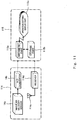
- FIG. 2 is a block diagram showing one example of the internal configurations of a shake detector and an arithmetic unit in the center-of-gravity detection system of the present embodiment.
- the shake detector 14 is firmly secured in the middle, relative to the horizontal direction, of the trailer truck 50, i.e., in the location causing no impedance to the transport work on the side of the tractor 10 (for example, in the vicinity of the coupler 13).
- the arithmetic unit 15 is installed in place in the driver's cabin of the tractor 10. And, the both devices are so connected together as to establish data transmission therebetween by wire communication, wireless communication or the like via suitable data input/output ports (not shown).
- the shake detector 14 includes a biaxial (two-dimensional) angular velocity sensor 14a having angular velocity-sensitive axes aligned so as to sense shake in the vertical and width directions of the container cargo vehicle of the trailer truck 50 during travel, and an A/D (analog/digital) converter 14b for the conversion of an analog signal output from the angular velocity sensor 14a into a digital signal.
- a biaxial (two-dimensional) angular velocity sensor 14a having angular velocity-sensitive axes aligned so as to sense shake in the vertical and width directions of the container cargo vehicle of the trailer truck 50 during travel
- an A/D (analog/digital) converter 14b for the conversion of an analog signal output from the angular velocity sensor 14a into a digital signal.
- the size of angular velocity signal digitalized by the A/D converter 14b is proportional to the angular velocity of shake in the vertical and width directions of the container cargo vehicle of the trailer truck 50 during travel.
- the biaxial angular velocity sensor 14a may be implemented by a sensor of the crystal tuning fork type or a sensor of the oscillation type, which is however not considered limitative.
- a triaxial (three-dimensional) angular velocity sensor or a velocity sensor may be employed as a substitute for the angular velocity sensor 14a.
- the shake detector 14 containing therein the A/D converter 14b is exemplarily shown in consideration of convenience at the time of use of the shake detector 14, but the A/D converter 14b may be in the form of an external A/D converter.
- the shake detector 14 contains therein various signal processing circuits such as a filter (not shown), an amplifier (not shown), and other like means, but their detailed description is omitted here because they are commonly-used art.
- the arithmetic unit 15 includes an arithmetic part 15a comprised of a microprocessor or the like, a storage part 15b comprised of ROM (Read Only Memory), RAM (Random Access Memory), or the like, and an operation setting/display part 15c.
- an information mobile terminal such as a personal computer of the notebook type or the like.
- the storage part 15b is connected to the arithmetic part 15a, and stores an arithmetic program for properly deriving the 3D center-of-gravity location of the container cargo vehicle and various input constants (to be hereinafter described) necessary for performing arithmetic to calculate the 3D center-of-gravity location.
- the arithmetic part 15a operates according to the arithmetic program pre-stored in the storage part 15b.
- the arithmetic part 15a is capable of deriving, based upon the digital signal output from the shake detector 14 (the A/D converter 14b), the 3D center-of-gravity location of the container cargo vehicle, as will be described later.
- the operation setting/display part 15c includes a console part (for example, a keyboard (not shown)) on which setting buttons for entry of the aforesaid input constants are arrayed, and an information notifying device (for example, such as liquid crystal panel display, loudspeaker (not shown)) that provides information either in displayed or audible manner so that the output data about the 3D center-of-gravity location of the container cargo vehicle output from the arithmetic part 15a can be recognized by the operator (driver or fellow passenger).
- a console part for example, a keyboard (not shown)
- an information notifying device for example, such as liquid crystal panel display, loudspeaker (not shown)
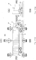
- FIGS. 3 , 4 , and 5 are each a schematic illustration for the purpose of describing the method of deriving the 3D center-of-gravity location of the container cargo vehicle by means of the center-of-gravity detection system of the present embodiment.
- FIGS. 3 and 4 are views as viewed from the front/rear direction in which the trailer truck travels.
- FIG. 5 is a view as viewed from the vertical direction in which the self-weight of the trailer truck is applied.
- FIGS. 3 , 4 , and 5 the configuration of the center-of-gravity detection system 100 is shown in simplified manner or omitted for the sake of facilitating the understanding of the method of deriving the 3D center-of-gravity location.
- the container 11 when placed on the container chassis 12, is supported by the buffer elastic force (for example, air pressure and spring force) of suspensions 205 (suspension devices (see FIG. 4 )) disposed in the tractor 10 and the container chassis 12, and is in neutral at a constant level of height from a road surface 204. If, in this condition, the trailer truck 50 travels, its tires will keep “treading" on irregularities of the road surface 204, and, as a result, random external disturbances will be transmitted via the suspensions 205 to the vehicle body (the container 11) of the trailer truck 50.
- the buffer elastic force for example, air pressure and spring force
- the trailer truck 50 oscillates based upon the motion having a characteristic period (frequency) dependent on the elastic force of the suspensions 205, the total weight of the container cargo vehicle, and the location of the center of gravity thereof. And, this motion is detected, by the shake detector 14, as a reciprocation motion in the vertical direction of the center of gravity W of the container cargo vehicle (to be correct, the pitching of the tractor 10 to be hereinafter described) and as a horizontal simple pendulum motion of the center of gravity, W, of the container cargo vehicle.
- the suspension 205 means a member capable of buffering vibration, from the road surface 204, of the vehicle body of the trailer truck 50 and includes other than a spring type buffer coupled to an axle, for example tires arranged at the ends of the axle and filled with air.
- the former motion corresponds to a behaviour that is called the "pitching" of the tractor 10.
- the coupler 13 by which the tractor 10 and the container chassis 12 are coupled together, is pushed vertically. Since the position of the coupler 13 resides behind the tractor 10, the front section of the tractor 10 conversely sinks and floats by the coupler 13 being pushed vertically. This phenomenon is the pitching of the tractor 10. That is to say, the reciprocation motion, in the vertical direction, of the container cargo vehicle is transmitted through the coupler 13 to the tractor 10, thereby causing the tractor 10 to undergo pitching.
- each of the rear, front, right, and left axles is provided with a respective suspension 205; however, from the fact that these behaviours (vertical reciprocation motion and horizontal simple pendulum motion) occur at the same time, it can be considered reasonable that, in taking account into the dynamic elastic coefficient (the constant of spring), the analysis of the behaviours is conducted by simply assuming that a single respective elastic body (spring) is mounted on each of the right and left axles. The validity of this assumption has been confirmed by a first verification experiment (to be hereinafter described) conducted by using a real car.
- Patent Document 2 a characteristic quantity, such as the moment of inertia of a vehicle, is decided on the assumption of measuring the elastic coefficient of a suspension
- Patent Document 6 a characteristic quantity, such as the moment of inertia of a vehicle
- the elastic coefficient of the suspension 205 varies depending on the manufacturers of the tractor 10 and the container chassis 12, the type of vehicle, the model year, and the degree of aging.
- the manufactures, the vehicle type, the model year, and the degree of aging in view of the actual conditions of the transport operation of the container 11.
- containers are daily transported by trailer trucks (the trailer truck 50) composed of any combinations (practically speaking, numberless combinations) of an indefinite number of tractors (the tractor 10) and an indefinite number of container chassis (the container chassis 12).
- Patent Document 1 there is a technique (for example, Patent Document 1) on the assumption that a large number of detectors are disposed in a chassis on the side of a container (which corresponds to the container chassis in the present specification); however, as can be easily imagined from the fact that the numeric quantity of container chassis dealt with in the container transport operation is huge, there is no way that this means is practical in view of the costs.
- the period T' of a vertical reciprocation motion of the center of gravity W of the container cargo vehicle (the period corresponding to the pitching period of the tractor 10) is expressed in a formula where the center of gravity W of the container cargo vehicle is a mass point.
- T ' 2 ⁇ m 2 k
- T' is the period of the vertical reciprocation motion of the center of gravity W of the container cargo vehicle.
- k is the elastic coefficient (the constant of spring) of one of the right and left-hand suspensions 205.
- m is the weight of the container cargo vehicle, and ⁇ is the circle ratio ( pi ).
- the period T of a horizontal simple pendulum motion of the center of gravity W of the container cargo vehicle (the period corresponding to the rolling period of the trailer truck 50) is expressed in a formula where the center of gravity W of the container cargo vehicle is a mass point.
- f is the force that is imparted in the tangential direction of the rolling circle (rotating circle) to the center of gravity W of the container cargo vehicle.
- ⁇ is the rolling angle.
- L is the length from the axle center to the center of gravity W of the container cargo vehicle.
- b is the length of a portion that supports the load of the container 11, and is the constant established for each container 11.
- the lower case letter l is the vertical length from the axle to the center of gravity W of the container cargo vehicle, and is the value that represents the vertical location of the center of gravity W, in the cross-section surface perpendicular to the front/rear direction of the container 11, of the container cargo vehicle, as shown in FIG. 1(b) .
- s is the horizontal length from the center of the axle to the center of gravity W of the container cargo vehicle, and is the value that represents the horizontal location of the center of gravity W, in the cross-section surface perpendicular to the front/rear direction of the container 11, of the container cargo vehicle, as shown in FIG. 1(b) .
- x is the amount of displacement of each of the right and left-hand suspensions.
- g is the gravitational acceleration.
- expression (1) is expanded as given in expression (2) by the composition of trigonometric functions in parenthesis.
- expression (2) the angle of the sine function ( ⁇ + ⁇ ) obtained by the trigonometric function composition is represented as the rolling angle ⁇ ' .
- the central angle ⁇ of the rolling (simple pendulum motion) of the center of gravity W becomes zero.
- the central angle ⁇ indicates the angle formed by the vertical central line 201 and a rolling central line 206, as shown in FIG. 4 .
- ⁇ is, as described above, is the central angle of the rolling of the center of gravity W of the container cargo vehicle, and is the angle formed by the vertical central line 201 and the rolling central line 206.
- expression (3) becomes the following expression.
- f ⁇ mg L k b 2 2 mg ⁇ l 2 + k b 2 2 mg ⁇ l tan ⁇ 2
- T' the period of the vertical reciprocation motion of the center of gravity W of the container cargo vehicle
- T the period of the horizontal simple pendulum motion of the center of gravity W of the container cargo vehicle
- the angular velocity detected by the shake detector 14 is generally the angular frequency (hereinafter abbreviated as the "frequency") that corresponds to the angle/time, and this frequency is represented by the reciprocal of the period (1/period). Therefore, if the pitching frequency of the tractor 10 that corresponds to T' (the period of the vertical reciprocation motion of the center of gravity W ) is denoted as v' and, in addition, the rolling frequency thereof that corresponds to T (the period of the horizontal simple pendulum motion of the center of gravity W ) is denoted as v , then the aforesaid expressions can be reorganized to the following expressions, respectively.
- the location of the center of gravity W, in the cross-section surface perpendicular to the front/rear direction of the container 11, of the container cargo vehicle can be derived by solving the simultaneous equation of expressions (9) and (10) for l and s : however, the 3D center-of-gravity location of the container cargo vehicle still remains unspecified. That is, in addition to these values l and s, it is required that the center of gravity W in the front/rear direction (travel direction) of the container cargo vehicle be found.
- the location of the center of gravity W in the front/rear direction of the container cargo vehicle can be derived as follows.
- the container 11 placed on the container chassis 12 is supported by a rear and a front cross beam 21 and 20 of the container chassis 12.
- These front and rear cross beams 20 and 21 extend in the horizontal direction (width direction) of the container 11, and are firmly secured to longitudinal beams (not shown) existing in the front/rear direction.
- the load of the container 11 is dispersed, through the rear and front cross beams 21 and 20 and the longitudinal beams, to the tractor 10 coupled to the front section of the container chassis 12 and the suspensions 205 in the rear section of the container chassis 12.
- the strengths (amplitude) of rolling resulting from the external disturbances differs, as shown in FIG. 1(a) .
- FIG. 1(a) if the center of action of the external disturbance leaves the location of the center of gravity, the load of the trailer truck 50 against the external disturbance diminishes and, as a result, the rolling amplitude increases. Conversely, if the center of action of the external disturbance approaches the location of the center of gravity, the great load of the trailer truck 50 functions as a resistive force and, as a result, the rolling amplitude diminishes.
- the center of action of the external disturbance is the positions of the front and rear cross beams 20 and 21 of the container chassis 12 corresponding to the front and rear sections of the container 11, respectively.
- the front section of the container chassis 12 and the tractor 10 are coupled together by a disc-shaped coupling member called a coupler 13 and having a shorter length than the front cross beam 20 of the container chassis 12.
- the diameter of the coupler 13 is usually less than half the length of the front cross beam 20 of the container chassis. Therefore, the horizontal length of a support of the section that connects the tractor 10 to the container chassis 12 carrying the container 11 is not the length of the front cross beam 20 of the container chassis 12 but is the diameter b c of the coupler 13.
- the diameter b c of the coupler 13 to which the container chassis 12 is coupled is an essential particular for deriving the 3D center-of-gravity location; however, for the case of the lateral rollover limit velocity of the container cargo vehicle in a second embodiment of the invention, the state of single point coupling between the tractor 10 and the container chassis 12 (see a connection point E shown in FIG. 13 ) by the couple 13 has a great significance. That is to say, both the member that forms the diameter b c and the member that forms the connection point E are the coupler 13, but these members differs from each other in their technical significance. The technical significance of the connection point E will be described in detail.
- the rolling frequency v depends upon the values l and s each representative of the location of the center of gravity W of the container cargo vehicle and the length b of the section supporting the container 11, provided that k / m is a constant value.
- the length b differs between at the front section and at the rear section of the container chassis 12 and, therefore, it is conceivable that the maximum peak amplitude (convex peak's vertex) resides at two locations where the rolling phenomenon significantly appears in the direction in which the amplitude of rolling increases.
- the maximum peak amplitude includes one that is originated from the coupler 13 as a coupling member for connection between the front section of the container chassis 12 and the tractor 10 and another that is originated from the rear cross beam 21 positioned in the rear section of the container chassis 12. And, from the consideration of expression (5), the frequency corresponding to the latter maximum peak amplitude is larger than that of the former one.
- This minimum peak amplitude is a peak originated from the center of gravity W in the front/rear direction of the container cargo vehicle.
- b 2 is the substantial horizontal length of the member which supports the container 11 at the location of the rear section of the container 11, and is the value that is determined as a constant.
- b 1 is the substantial horizontal length of the member which supports the container 11 in the location of the front section of the container 11, and is the value that is geometrically determined as a constant from b c (the diameter of the coupler 13 of the tractor 10).
- v 1 is the frequency of rolling generated when external disturbance acts in a perpendicular direction from the road surface 204 in the front section of the container 11.
- v 2 is the frequency of rolling generated when external disturbance acts in a perpendicular direction from the road surface 204 in the rear section of the container 11.
- b g (the substantial horizontal length of the member which supports the container 11 in the location of the center of gravity W in the front/rear direction of the container cargo vehicle) is specified.
- This length b g is found from expression (13) when the frequencies ( v 1 , v 2 , v g ) are all known (that is, when the arithmetic unit 15 succeeds in specifying, with the aid of the shake detector 14, the frequencies ( v g , v l , v s )).
- v g is the frequency of rolling when external disturbance acts in a perpendicular direction from the road surface 204 in the location of the center of gravity W.
- b g b 1 2 ⁇ b 2 2 v 1 2 ⁇ v 2 2 v g 2 + b 2 2 v 1 2 ⁇ b 1 2 v 2 2 v 1 2 ⁇ v 2 2
- the values l and s each representative of the location of the center of gravity W , in the cross-section surface perpendicular to the front/rear direction of the container 11, of the container cargo vehicle, and corresponding to the length k g can be derived by use of the length b g as b in expression (10), in conjunction with expression (9).
- the center-of-gravity detection system 100 of the present embodiment is able to obtain all of the three numerical values l , s, and k g each representing the location of the center of gravity W, in three-dimensional space, of the container cargo vehicle.
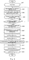
- FIG. 6 is a flow chart representing a routine of detecting the 3D center-of-gravity location by means of the center-of-gravity detection system of the present embodiment.
- a plurality of menus are displayed on the display screen (not shown) of the operation setting/display part 15c.
- buttons of the operation setting/display part 15c it becomes possible to start the operation of detecting the 3D center-of-gravity location during travel of the trailer truck 50.
- the arithmetic part 15a of the arithmetic unit 15 retrieves, from the storage part 15b, an arithmetic program for 3D center-of-gravity location detection and prestored suitable constants, and the arithmetic program executes the following processing while controlling the arithmetic part 15a, the storage part 15b, and the operation setting/display part 15c.
- the constants include, for example, p (the front/rear-directional length of the container 11), b c (the diameter of the coupler 13 of the tractor 10), k c (the length from the front section of the container 11 to the center of the coupler 13), b 2 (the substantial horizontal length of the member which supports the container 11 in the location of the rear section of the container 11), g (the gravitational acceleration), and ⁇ (the circle ratio ( pi )).
- the constants p, b c , k c , and b 2 are often standard values and, therefore, it is preferred that these constants p, b c , k c , and b 2 be prestored in the storage part 15b to save the operations of confirming and inputting the constants.
- step S601 the tractor 10 towing, along with the container chassis 12, the container 11 carrying the cargo is made to travel on the road surface 204 (step S601).
- the trailer truck 50 be made to travel in a straight line to the flow of normal traffic in the light of properly estimating ⁇ (the central angle of rolling of the center of gravity W of the container cargo vehicle).
- Patent Document 1 As an additional remark to the above, of the aforesaid prior art technologies, there is an example (for example, Patent Document 1, 5, or 6) in which data during travel of the truck along a curved road section (for example, centrifugal force and lateral acceleration) are intentionally detected; however, such a technique may end up causing the truck during travel along a curve (during data acquisition) to undergo unstable travel motion (truck lateral rollover, at worst), and there is still a question as to whether or not its practical use is really possible.
- a curved road section for example, centrifugal force and lateral acceleration
- step S602 When the operation of detecting the 3D center-of-gravity location is commenced by the manipulation of buttons of the operation setting/display part 15c by the operator (for example, the driver of the tractor 10 or a fellow passenger), data about the angular velocities of pitching corresponding to the vertical reciprocation motion of the center of gravity W and rolling (horizontal simple pendulum motion) of the center of gravity W are measured as analog signals by means of the angular velocity sensor 14a of the shake detector 14 (step S602).
- the analog angular velocity data are sampled, by the arithmetic unit 15 (the arithmetic part 15a), as digital signals through the A/D converter 14b of the shake detector 14, for every predetermined sampling period of time (for example, every 0.01 seconds) prestored in the storage part 15b (step S603), and the digital angular velocity data thus sampled are stored, together with time-series data, in the storage part 15b (step S604).
- the arithmetic part 15a makes a decision whether or not to terminate the measurement of angular velocity data by the angular velocity sensor 14a (step S605). If the arithmetic part 15a decides that the angular velocity data measurement may be terminated (in the case of "Yes” in step S605), then the detection routine moves to the subsequent processing steps (step S606 onward). On the other hand, if the arithmetic part 15a does not decide that the measurement of the angular velocity data may be terminated (in the case of "No” in step 6605), then the processing of the aforesaid steps S602-604 is continued.
- the decision of whether or not the measurement may be terminated can be made based upon a predetermined length of measurement time that is derived from a required total number of samples prestored in the storage part 15b and the aforesaid sample time.
- a predetermined length of measurement time that is derived from a required total number of samples prestored in the storage part 15b and the aforesaid sample time.
- the results of a first verification experiment shows that if the number of samples, at which the statistical error of sampling becomes considerably diminished, is 4096 (since FFT is an analysis intended for the number of integer multipliers of 2, 2 12 is shown here as an example number of samples) and, in addition, if the sample time is 0.01 seconds, then the minimum required measurement time is: 4096 ⁇ 0.01 S ⁇ 40 S.
- the arithmetic part 15a makes a decision that the measurement of angular velocity data may be brought to a stop after an elapse of 40 seconds or more since the time when the angular velocity sensor 14a started measuring angular velocity data.
- the time of measurement should be kept as short as possible, but if too short, this means a less number of samples, thereby resulting in increase in the statistical error.
- the results of the hereinafter described first verification experiment show that statistical error-reduced, stable data are obtained if the measurement of data is conducted for two minutes as a length of time serving as a guide.
- the arithmetic part 15a may make a decision whether or not to terminate the measurement of angular velocity data based on the presence or absence of the manipulation of a measurement terminating button of the operation setting/display part 15c by the operator.
- the measurement of angular velocity data conducted in such a short period of time serves as a basis for the elimination of these numerical values k and m in the formulation of the foregoing simultaneous equation, based on the precondition that k (the elastic coefficient of the suspension 205) and m (the weight of the container cargo vehicle) are invariable in the period of the angular velocity data measurement.
- the arithmetic part 15a performs fast Fourier transform (FFT) on time-series angular velocity data stored in the storage part 15b, thereby to convert the angular velocity data into data of the amplitude with respect to the frequency (step S606).
- FFT fast Fourier transform
- the frequencies v l , v g , v 2 are specified based upon the aforesaid theory of dynamics (step S607).
- the frequency v' is specified based upon the aforesaid theory of dynamics (step S607).
- the lowest two of the values of the frequency of rolling (the first two values in ascending order) corresponding to rolling's maximum peak amplitudes (vertexes) are selected and, in addition, a frequency value corresponding to a minimum peak amplitude (valley) located between the maximum peak amplitudes (in the present embodiment, one that is located almost midway therebetween) is selected.
- the three frequency values thus selected correspond respectively to the frequency v l , to the frequency v g , and to the frequency v 2 in ascending order of value.
- a frequency value corresponding to the maximum amplitude of pitching is selected as the frequency v'.
- the arithmetic part 15a retrieves the constants b c and b 2 prestored in the storage part 15b, and uses the frequencies v l , v g , v 2 obtained in step S607 to perform arithmetic to calculate the substantial horizontal length bg of the member which supports the container 11 in the location of the center of gravity W from expression (13) (step S608).
- b g b 1 2 ⁇ b 2 2 v 1 2 ⁇ v 2 2 v g 2 + b 2 2 v 1 2 ⁇ b 1 2 v 2 2 v 1 2 ⁇ v 2 2
- b 2 is the substantial horizontal length of the member which supports the container 11 in the location of the rear section of the container 11.
- b 2 is the value that is determined as a constant.
- b 1 is the substantial horizontal length of the member which supports the container 11 in the location of the front section of the container 11.
- b 1 is the value that is geometrically determined based on a constant from b c (the diameter of the coupler 13 of the tractor 10).
- v 1 is the frequency of rolling generated when external disturbance acts in a perpendicular direction from the road surface 204 in the front section of the container 11.
- v 2 is the frequency of rolling generated when external disturbance acts in a perpendicular direction from the road surface 204 in the rear section of the container 11.
- v g is the frequency of rolling when external disturbance acts in a perpendicular direction from the road surface 204 in the location of the center of gravity W.
- the arithmetic part 15a retrieves the constants p, k c , b c prestored in the storage part 15b, and uses the length b g obtained in step S608 to perform arithmetic to calculate the length, k g , from the front section of the container 11 to the location of the center of gravity W from expression (14) (step S609).
- k g p ⁇ k b 2 ⁇ b c b g ⁇ b c + k c
- p is the front/rear-directional length of the container 11.
- k c is the length from the front section of the container 11 to the center of the coupler 13.
- b c is the diameter of the coupler 13 of the tractor 10.
- the arithmetic part 15a retrieves time-series angular velocity data stored in the storage part 15b.
- the central angle ⁇ of rolling of the center of gravity W of the container cargo vehicle corresponding to the time average value of temporal change in the amplitude of rolling is specified from the distribution representing the change with time in the amplitude (angle) of rolling (hereinafter abbreviated as the "temporal change in the amplitude of rolling”) (step S610).
- the arithmetic part 15a retrieves the constants g and ⁇ prestored in the storage part 15b and uses the frequencies v g and v' obtained in step S607, the central angle ⁇ obtained in step S610, and the length b g obtained in step S608 to perform arithmetic to calculate, from expression (10') corresponding to expression (10) (that is, v in expression (10) is denoted as v g in expression (10') and b in expression (10) is denoted as b g in expression (10')), the vertical length l from the axle to the center of gravity W of the container cargo vehicle in the perpendicular cross-section surface at the position of k g (step S611).
- g is the gravitational acceleration.
- ⁇ is the circle ration ( pi ).
- ⁇ is the central angle of rolling of the center of gravity W of the container cargo vehicle.
- v' is the pitching frequency.
- v g is the frequency of rolling when external disturbance acts in a perpendicular direction from the road surface 204 in the location of the center of gravity W.
- b g is the substantial horizontal length of the member which supports the container 11.
- the arithmetic part 15a retrieves the constants g and ⁇ prestored in the storage part 15b and uses the frequency v' obtained in step S607, the central angle ⁇ obtained in step S610, the length b g obtained in step S608, and the length l obtained in step S611 to perform arithmetic to calculate, from expression (9') corresponding to expression (9) (that is, b in expression (9) is denoted as b g in expression (9')), the horizontal length s from the center of the axle to the center of gravity W of the container cargo vehicle in the perpendicular cross-section surface at the position of k g (step S612).
- s ⁇ 2 v ' 2 b g 2 g ⁇ l tan ⁇
- g is the gravitational acceleration.
- ⁇ is the circle ratio ( p i).
- ⁇ is the central angle of rolling of the center of gravity W of the container cargo vehicle.
- v ' is the pitching frequency.
- b g is the substantial horizontal length of the member which supports the container 11.
- l is the vertical length from the axle to the center of gravity W of the container cargo vehicle in the perpendicular cross-section at the position of k g .
- step S609 the length k g obtained in step S609, the length l obtained in step S611, and the length s obtained in step S612 are displayed on the display screen of the operation setting/display part 15c by the arithmetic part 15a (step S613), and a series of 3D center-of-gravity location detection routines is brought into completion.
- the center-of-gravity detection system 100 of the present embodiment includes: the trailer truck 50 having the container 11 capable of carrying cargo, the container chassis 12 on which the container 11 is placed, and the tractor 10 for towing the container chassis 12; the biaxial angular velocity sensor 14a for the detection of shakes in the self-weight and width directions of the container cargo vehicle during straight travel of the trailer truck 50; and the arithmetic unit 15.
- the arithmetic unit 15 is configured so as to derive, based upon the physical quantities that correlate with the shakes (to be exact, the frequency of rolling and the central angle of rolling), the center of gravity, in three-dimensional space, of the container cargo vehicle.
- the 3D center-of-gravity location of the container cargo vehicle is valuable data that directly reflects the degree of biasing of the load of container cargo whose condition of loading is unknown and, therefore, this makes it possible to contribute to preventing the cargo from pile collapse/falling when the container door is opened, and the container transport vehicle from unstable travel motion on the curved road section.
- the 3D center-of-gravity location of the container cargo vehicle is derived based upon the logical theory of dynamics, without having to introduce data that lack theoretical ground (e.g., correction coefficient or the like) and, as a result, the reliability thereof is extremely high. And, this is confirmed by the results of the first verification experiment conducted by using an actual car (to be hereinafter described).
- center-of-gravity detection system 100 of the present embodiment provides various advantageous effects as described below.
- biaxial angular velocity sensor 14a is installed by simple means (such as adhesive joint or bolt fastening (not shown)) in a suitable place in the tractor 10 for arithmetic calculation of the 3D center-of-gravity location of the container cargo vehicle by means of the center-of-gravity detection system 100. Stated another way, this is preferable because there is no need to take any measures against great numbers of containers 11 and container chassis 12 that are handled in the container transport operation.
- a standard 40-feet container was loaded with dummy cargo for experimental use of about 9.5 tons (about 9.5 ⁇ 10 3 kg).
- the length k g from the container front section to the location of the center of gravity, the vertical length l from the axle to the center of gravity of the container cargo vehicle in the perpendicular cross-section surface at the position of k g , and the horizontal length s from the center of the axle to the center of gravity of the container cargo vehicle in the perpendicular cross-section surface at the position of k g are adjusted as follows.
- the dummy cargo is loaded, together with the container, on the container chassis and the container chassis is towed by a tractor.
- the tractor travelled to the flow of traffic for a couple of minutes on a straight course of a general road among other container transport vehicle.
- angular-velocity digital signals output from the angular velocity sensor disposed in the tractor were sampled by the personal computer, and the sampled digital signals were sequentially stored, together with time-series data, in the internal memory of the personal computer. Such sampling was performed at intervals of 0.01 seconds.
- the rolling frequency/amplitude distribution, the pitching frequency/amplitude distribution, and the temporal change in the rolling amplitude are displayed on the computer screen by means of angular velocity digital signals after fast Fourier transform (FFT) performed by the personal computer.
- FFT fast Fourier transform
- FIG. 7 there is shown a diagram representing one example of the rolling frequency/amplitude distribution wherein the horizontal axis represents the frequency (Hz) and the vertical axis represents the amplitude (angular velocity).
- FIG. 8 is a diagram showing one example of the pitching frequency/amplitude distribution wherein the horizontal axis represents the frequency (Hz) and the vertical axis represents the amplitude (angular velocity).
- FIG. 9 is a diagram showing one example of the temporal change in the rolling amplitude wherein the horizontal axis represents the time (second) and the vertical axis represents the rolling amplitude.
- the personal computer uses a suitable mathematical extraction method to extract, as frequencies corresponding to the peak amplitudes, v 1 (the frequency of rolling generated when external disturbance acts in the perpendicular direction from the road surface in the front section of the container), v 2 (the frequency of rolling generated when external disturbance acts in the perpendicular direction from the road surface in the rear section of the container), v g (the frequency of rolling generated when external disturbance acts in the perpendicular direction from the road surface in the location of the center of gravity), and v' (the frequency corresponding to the maximum amplitude of pitching), as shown below.
- the personal computer computes ⁇ (the central angle of rolling of the center of gravity), as shown below.
- the personal computer uses the constants inherent to the container, the tractor, and the container chassis, thereby to perform arithmetic to estimate, from the theoretical equations stored in the internal memory, k g (the length from the container front section to the location of the center of gravity), l (the vertical length from the axle to the center-of-gravity of the container cargo vehicle in the perpendicular cross-section surface at the position of k g ), and s (the horizontal length from the center of the axle to the center-of-gravity of the container cargo vehicle in the perpendicular cross-section surface at the position of k g ).
- the results of the arithmetic estimation are arranged in the following Table 1 for comparison with values obtained by actual measurement of the dummy cargo.
- the foregoing constants include p (the front/rear-directional length of the container), b c (the diameter of the coupler of the tractor), k c (the length from the front section of the container to the center of the coupler), and b 2 (the substantial horizontal length of the member which supports the container in the location of the rear section of the container).
- p the front/rear-directional length of the container
- b c the diameter of the coupler of the tractor
- k c the length from the front section of the container to the center of the coupler
- b 2 the substantial horizontal length of the member which supports the container in the location of the rear section of the container.
- the measurement error of the actual measurement values includes, for example, read errors occurring when measuring the dimensions of the dummy cargo and the location of loading in the container with a measuring tool. If so, it is conceivable that the estimated arithmetic values of the present example obtained based upon the exact theory of dynamics are less subjected to the possibility of being mixed with errors rather than the actual measurement values, and, therefore it is assumed that the estimated arithmetic values seem more truly representative of the center-of-gravity location when compared to the actual measurement values.
- FIG. 10 is an outline illustration showing an example of the configuration of a lateral rollover limit velocity estimation system according to a second embodiment of the invention.
- FIG. 10(a) is a view of the estimation system as viewed from the width direction (sideways) of the container cargo vehicle.
- FIG. 10(b) is a view of the estimation system as viewed from the rear side of the container cargo vehicle.
- the direction in which the self-weight of the container cargo vehicle is applied is referred to as the "vertical direction”
- the width direction of the container cargo vehicle is referred to as the “horizontal direction”
- the travel direction of the container cargo vehicle is referred to as the "front/rear direction”.
- the lateral rollover limit velocity estimation system 110 is provided with a trailer truck 50, a data detection part 114, and an arithmetic unit 115.
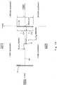
- FIG. 11 is a block diagram showing one example of the internal configurations of the data detection part and the arithmetic unit in the lateral rollover limit velocity estimation system according to the present embodiment.
- the data detection part 114 is firmly secured in the middle, relative to the horizontal direction, of the trailer truck 50 in the location that causes no impedance to the transport work on the side of the tractor 10 (for example, in the vicinity of the coupler 13 shown in FIG. 10 ).
- the arithmetic unit 115 is disposed in place within the driver's cabin of the tractor 10. And, the both are connected together such that data is transmittable therebetween by wire communication, wireless communication or the like via suitable data input/output ports (not shown).
- the data detection part 114 contains therein the same devices as the components of the shake detector 14 described in the first embodiment. That is, the data detection part 114 includes, as shown in FIG. 11 , a biaxial (two-dimensional) angular velocity sensor 14a having angular velocity sensitive axes so aligned as to sense shakes in the vertical and width directions of the container cargo vehicle of the trailer truck 50 during travel, and an A/D (analog/digital) converter 14b for the conversion of analog signal output from the angular velocity sensor 14a into digital signal.
- a biaxial (two-dimensional) angular velocity sensor 14a having angular velocity sensitive axes so aligned as to sense shakes in the vertical and width directions of the container cargo vehicle of the trailer truck 50 during travel
- an A/D (analog/digital) converter 14b for the conversion of analog signal output from the angular velocity sensor 14a into digital signal.
- the data detection part 114 also includes a receiver 114d for receiving various traffic radio intelligence from a local ITS (Intelligent Transport System (advanced transport system)) through an antenna 114c and feeding the traffic information to the arithmetic unit 115.
- the traffic radio intelligence in the present embodiment includes information about the road surface 204 on which the trailer truck 50 is scheduled to travel (for example, radio intelligence about the curvature radius of a curved road section 204c).
- the arithmetic unit 115 has an arithmetic part 115a which is comprised of a microprocessor or the like, a storage part 115b which is comprised of ROM (Read Only Memory), RAM (Random Access Memory) or the like, and an operation setting/display part 115c.
- arithmetic unit 115 there is an information mobile terminal such as a personal computer of the notebook type.
- the storage part 115b stores, in addition to the arithmetic program for properly deriving the 3D center-of-gravity location of the container cargo vehicle and the various input constants required for that arithmetic described in the first embodiment, another arithmetic program for properly deriving the lateral rollover limit velocity of the container cargo vehicle and various input constants (to be hereinafter described) required for that arithmetic.
- the arithmetic part 115a operates according to the program, prestored in the storage part 115b, for use in sensing the 3D center-of-gravity location, and is able to derive, based upon the digital signal output from the angular velocity sensor 14a (the A/D converter 14b), the 3D center-of-gravity location of the container cargo vehicle; however, its detailed description is omitted here.
- the arithmetic part 115a operates according to the arithmetic program, prestored in the storage part 115b, for use in predicting the lateral rollover limit velocity, and is able to derive, for example, by means of the aforesaid 3D center-of-gravity location, the lateral rollover limit velocity of the container cargo vehicle in response to the curvature radius of the curved road section 204c along which the container cargo vehicle travels. Furthermore, the arithmetic part 115a is able to sequentially obtain, from the receiver 114d, radio intelligence about the curvature radius of the curve road section 204c along which the trailer truck 50 is scheduled to travel.
- the operation setting/display part 115c includes a console part (for example, a keyboard (not shown)) on which setting buttons for the aforesaid input constants are arrayed, and an information notifying device (for example, a liquid crystal panel display, a loudspeaker et cetera (not shown)) that provides information either in displayed or audible manner so that the output data about the lateral rollover limit velocity of the container cargo vehicle output from the arithmetic part 115a can be recognized by the operator. That is, the arithmetic part 115a is configured such that the aforesaid lateral rollover limit velocity is pre-notified to the operator (the driver or a fellow passenger) with the aid of the operation setting/display part 115c.
- a console part for example, a keyboard (not shown)
- an information notifying device for example, a liquid crystal panel display, a loudspeaker et cetera (not shown)
- the arithmetic part 115a is configured such
- FIGS. 12 and 13 are schematic illustrations for the purpose of explaining a method of deriving the lateral rollover limit velocity of the container cargo vehicle by means of the lateral rollover limit velocity estimation system of the present embodiment.
- FIG. 12 is a view of the trailer truck (container cargo vehicle) as viewed from the rear thereof, when the trailer truck makes a right-hand turn along the curved road section. That is, the wheel on the left-hand side of the trailer truck 50 corresponds to a turning outer wheel while the wheel on the right-hand side of the trailer truck 50 corresponds to a turning inner wheel.
- FIG. 13(a) is a view of the trailer truck as viewed from the vertical direction in which the self-weight of the trailer truck is applied, when the trailer truck makes a right-hand turn along the curved road section.
- FIG. 13(b) is a view as viewed from the horizontal direction corresponding to the width direction of the trailer truck.
- FIGS. 12 and 13 with respect to the configuration of the lateral rollover limit velocity estimation system 110, it is shown in a simplified manner or omitted for the sake of facilitating the understanding of the method of deriving the lateral rollover limit velocity.
- FIG. 12 the conditions for velocity in the event that the container cargo vehicle inclines (or undergoes lateral rollover at worst) in the cross-section surface perpendicular to the front/rear direction (travel direction) of the container cargo vehicle will be explained.
- the force F centrifugal force F
- the trailer truck 50 inclines, centered on an outer edge 300 relative to the width direction of the turning outer wheel of the trailer truck 50, along the circumference of a circle having a radius of R (the distance from the outer edge 300 to the center of gravity W ).
- m is the weight of the container cargo vehicle and g is the gravitational acceleration.
- b is the width dimension of the container cargo vehicle, and is the value equivalent to the length of the section which supports the load of the container 11 as described in the first embodiment.
- the width dimension b is a characteristic value of the container cargo vehicle (the characteristic numeric value specified per container cargo vehicle; same as below).
- V is the travel velocity of the trailer truck 50 (container cargo vehicle)
- r is the curvature radius of the curved road section 204c
- a is the height from the road surface 204 of the curved road section 204c to the center of gravity W
- s is the horizontal length from the vertical central line 201 to the center of gravity W of the container cargo vehicle.
- the velocity at which the container cargo vehicle is brought into rotation centered on the outer edge 300 of the turning outer wheel of the container cargo vehicle can be found in the connection with the curvature radius r of the curved road section 204c, by means of the center-of-gravity location of the container cargo vehicle relative to the cross-section surface perpendicular to the travel direction of the container cargo vehicle.
- the trailer truck 50 when the trailer truck 50 makes a turn along the curved road section 204c, the centrifugal force F is applied evenly to the trailer truck 50 along the horizontal central line 207 of the trailer truck 50, the trailer truck 50 only skids within the horizontal plane of the curved road section 204c even when the road surface 204 of the cured road section 204c is in a slippery state. It is conceivable that the consequence in this case finally results in the problem of course-out of the trailer truck 50 from the curved road section 204c.
- the inventor of the present application has found, in addition to the induction that the tractor 10 and the container cargo vehicle (container chassis 12) form a bent (jackknife), the following: in the event of such a travel motion, there is the case where rotational motion in horizontal plane acts simultaneously with and independently of the aforesaid rotational motion of the container cargo vehicle in the cross-section surface perpendicular to the travel direction of the container cargo vehicle and each of these motion forces accidentally momentarily coincides with the other in the direction that causes the container cargo vehicle to tilt.
- W is the center of gravity of the container cargo vehicle.
- the upper case letter I is the point of contact of the front wheel of the tractor 10 to the road surface 204. That is, the contact point I is located on the road surface 204 immediately under the axle center of the front wheel of the tractor 10.
- the upper case letter C is the point of contact of the rear wheel of the tractor 10 to the road surface 204. That is, the contact point C is located on the road surface 204 immediately under the axle center of the rear wheel of the tractor 10.
- the contact point D is the point of contact of the middle, relative to the front/rear direction, of the wheels of the container chassis 12 to the road surface 204. That is, the contact point D is located on the road surface 204 immediately under the middle, relative to the front/rear direction, of the wheels arranged in two rows in the front/rear direction.
- the wheels of the container chassis 12 may be arranged either in a single row in the front/rear direction or in three or more rows in the front/rear direction. Even in such cases, the contact point D may be determined based upon the middle, relative to the front/rear direction, of the wheels arranged in the front/rear direction (the axle center in the case where the wheels are arranged in a single row).
- E is the point of connection between the tractor 10 and the container chassis 12 (container cargo vehicle) and, as described above, corresponds to the point-like connection position of the coupler 13 shown in FIGS. 1 and 10 .
- a is the height from the road surface 204 of the curved road section 204c to the center of gravity W.
- s is the horizontal length from the horizontal central line 207 (the vertical central line 201 in FIG. 12 ) to the center of gravity W in horizontal plane of the container cargo vehicle.
- b is the width dimension of the container cargo vehicle.
- the lower case latter c is the length extending in the front/rear direction from the contact point C to the center of gravity W.
- d is the length extending in the front/rear direction from the contact point D to the center of gravity W.
- e is the length extending in the front/rear direction from the connection point E to the contact point C.
- f is the length extending in the front/rear direction from the contact point I to the connection point E.
- L is the length extending in the front/rear direction from the contact point C to the contact point D (in other words, the sum of the distance between the contact point C and the center of gravity W and the distance between the center of gravity Wand the contact point C, i.e., length c + length d ).
- the lengths e, f, L are characteristic values of the container cargo vehicle.
- the length kg from the front section of the container 11 to the center of gravity W is already known based on the method of deriving the 3D center-of-gravity location of the container cargo vehicle discussed in the first embodiment, it then becomes possible that the length c (extending in the front/rear direction from the contact point C to the center of gravity W ) and the length d (extending in the front/rear direction from the contact point D to the center of gravity W ) can be easily geometrically derived based upon the characteristic values of the container cargo vehicle (e.g., the position of wheels and the like).
- FIG. 13(a) shows that the centrifugal force F that is applied to the center of gravity W of the container cargo vehicle is divided into the component of a centrifugal force Fi that is applied to the contact point I, the component of a centrifugal force Fc that is applied to the contact point C, the component of a centrifugal force Fd that is applied to the contact point D, and the component of a centrifugal force Fe that is applied to the connection point E.
- resistance forces (reaction forces) from the road surface 204 and the coupler 13 (not shown in FIG. 13 ) at the connection point E against these centrifugal forces Fi, Fc, Fd, Fe are also shown by dotted arrows.
- centrifugal force Fe is expressed as follows.
- F e F ⁇ F d
- centrifugal force Fi is expressed as follows.
- F c F i f e
- F i F d L + e ⁇ F c
- F i F d L + e ⁇ F i f e
- centrifugal forces Fd, Fe, Fi, and Fc i.e., the components of the centrifugal force F that is applied to the center of gravity W of the container cargo vehicle, are all formulated by the location of the center of gravity W relative to the centrifugal force F and the travel direction of the container cargo vehicle.
- the centrifugal force Fd, the centrifugal force Fe, the centrifugal force Fi, and the centrifugal force Fc are found out from the moment balance of the trailer truck 50. That is to say, it is assumed that the moment balance of the trailer truck 50 holds at the stage in which the trailer truck 50 is not in rotation in horizontal plane, and, in this case, each of the centrifugal forces Fd, Fe, Fi, Fc is of course in balance with its respective reaction force.
- the moment balance of the trailer truck 50 becomes disrupted, and it is required to correctly find out the cause for such moment disruption.
- the length of the trailer truck 50 expands and contracts and, theoretically, there is the possibility that the moment balance of the trailer truck 50 may become disrupted even if each of the centrifugal forces Fd, Fe, Fi, Fc does not vary in magnitude.
- the length of each part of the trailer truck 50 remains unchanged. Therefore, the condition in which the magnitude of each of the centrifugal forces Fd, Fe, Fi, Fc varies from that when the moment balance holds is the only remaining cause for the moment balance disruption of the trailer truck 50.
- connection point E which is a movable part of the trailer truck 50 serves as an axis of rotation in horizontal plane of the trailer truck 50. Therefore, if either one of the following inequalities holds, this gives rise to an element that causes the trailer truck 50 to rotate in horizontal plane.
- m is the weight of the container cargo vehicle.
- V is the travel velocity of the container cargo vehicle.
- r is the curvature radius of the curved road section 204c.
- the velocity at which the container cargo vehicle is brought into rotation centered on the point of connection between the tractor 10 and the container cargo vehicle is found in connection with the curvature radius r of the curved road section 204c by means of the center-of-gravity location of the container cargo vehicle relative to the horizontal direction of the container cargo vehicle.
- the condition in which the container cargo vehicle is most likely to laterally overturn during travel along the curved road section 204c occurs when the rotational motion of the container cargo vehicle in the cross-section surface perpendicular to the travel direction of the container cargo vehicle (inequality (1)) and the rotational motion of the container cargo vehicle in horizontal plane (inequality (2)) act at the same time.
- the travel velocity of the container cargo vehicle in that case is obtained by solving the following simultaneous inequality composed of inequality (1) and inequality (2) by the travel velocity V of the container cargo vehicle. ⁇ m v 2 r a ⁇ mg b 2 ⁇ s > 0 m v 2 r 1 f + e
- g is the gravitational acceleration.
- b is the width dimension of the container cargo vehicle.
- r is the curvature radius of the curved road section 204c.
- a is the height from the road surface 204 of the curved road section 204c to the center of gravity W.
- s is the horizontal length from the horizontal central line 207 (the vertical central line 201) to the center of gravity W of the container cargo vehicle.
- c is the front/rear-directional length from the contact point C to the center of gravity W.
- d is the front/rear-directional length from the contact point D to the center of gravity W.
- e is the front/rear-directional length from the connection point E to the contact point C.
- f is the front/rear-directional length from the contact point I to the connection point E.
- L is the front/rear-directional length from the contact point C to the contact point D.
- the inequality (3) is the expression for finding the lateral rollover velocity range of the container cargo vehicle in which it is predicted that the container cargo vehicle will come to laterally overturn. Now, therefore, if at least the 3D center-of-gravity location of the container cargo vehicle is already known, this makes it possible to properly estimate the range of velocities (of the travel velocity V of the container cargo vehicle) in which inequality (3) holds, i.e., the range of lateral rollover velocities of the container cargo vehicle.
- the travel velocity V of the container cargo vehicle in the left side of inequality (3) increases to exceed a limit (critical) velocity at which it is predicted that the container cargo vehicle starts tilting.
- a limit velocity is referred to as the lateral rollover limit velocity V1 in the present specification.
- the lateral rollover limit velocity V1 of the container cargo vehicle is given by the following equality (4) as a result of connection of the right and left sides of inequality (3) by an equal sign.
- ⁇ V 1 g b 2 ⁇ s r a + 1 f + e
- the lateral rollover limit velocity V1 serves as a reference velocity for whether or not the container cargo vehicle is brought into lateral rollover, and is the valuable data necessary for properly deciding abnormality in the velocity of the container cargo vehicle on the curves road section 204s.
- FIG. 14 is a flow chart showing the operation of estimating the lateral rollover limit velocity of the container cargo vehicle by means of the lateral rollover limit velocity estimation system of the present embodiment.
- the arithmetic part 115a of the arithmetic unit 115 retrieves from the storage part 115b an arithmetic program for lateral rollover limit velocity estimation and suitable prestored constants, and the arithmetic program executes the following processing while controlling the arithmetic part 115a, the storage part 115b, and the operation setting/display part 115c.
- These constants thus retrieved include g (the gravitational acceleration), b (the width dimension of the container cargo vehicle), e (the front/rear-directional length from the connection point E to the contact point C ), f (the front/rear-directional length from the contact point I to the connection point E ), and L (the front/rear-directional length from the contact point C to the contact point D ).
- any one of the above-described constants other than the gravitational acceleration g is the characteristic value of the trailer truck 50, such constants are entered into the storage part 115b for each model of the trailer truck 50, as in the operation to be hereinafter described.
- the constants are input to the storage part 115b, they can be used as they are without reentry of them, unless there is made a change in the model of the trailer truck 50.
- the operator specifies the aforesaid constants e, f, b, L with reference to suitable materials such as the vehicle inspection certificate or manufacture specification document of the trailer truck 50. And, by manipulation of the operation setting/display part 115c by the operator, these constants e, f, b, L are entered into the storage part 115b of the arithmetic unit 115 (step S1401).
- the gravitational acceleration g as a constant is prestored in the storage part 115b because it is a universal value. In this way, the arithmetic part 115a obtains the constants e, f, b, L, g.
- the arithmetic part 115a obtains data related to the center of gravity of the container cargo vehicle by means of any one of the following methods. That is to say, the arithmetic part 115a obtains a (the height from the road surface 204 of the curved road section 204c to the center of gravity W), s (the horizontal length from the horizontal central line 207 (the vertical central line 201) to the center of gravity W of the container cargo vehicle), c (the front/rear-directional length from the contact point C to the center of gravity W ), and d (the front/rear-directional length from the contact point D to the center of gravity W ) (step S1402).
- a the height from the road surface 204 of the curved road section 204c to the center of gravity W
- s the horizontal length from the horizontal central line 207 (the vertical central line 201) to the center of gravity W of the container cargo vehicle
- c the front/rear-directional length from the contact point C to the center of gravity W
- d the front/re
- the arithmetic part 115a operates according to the arithmetic program, prestored in the storage part 115b, for detection of the 3D center-of-gravity location and then obtains, based upon the digital signal output from the angular velocity sensor 14a (A/D converter 14b) described in the first embodiment, the 3D center-of-gravity location of the container cargo vehicle.
- the arithmetic part 115a is able to perform arithmetic to calculate, from the data about the 3D center-of-gravity location, the center-of-gravity related data a, s, c, d by means of simple geometrical calculations. This is preferable because it allows the arithmetic part 115a to automatically obtain data of high accuracy from the 3D center-of-gravity location of the container cargo vehicle derived based upon the logical theory of dynamics.
- the method of deriving the 3D center-of-gravity location of the container cargo vehicle has been already described in detail in the first embodiment, and, therefore, its description is omitted here.
- the arithmetic part 115a is able to obtain the center-of-gravity related data a, s, c, d by the operator entering the center-of-gravity related data a, s, c, d by means of the operation setting/display part 115c.
- the accuracy of the 3D center-of-gravity location of the container cargo vehicle in the second method may be lower than that in the first method because of the measurement error of the center-of-gravity related data a, s, c, d.
- the arithmetic part 115a obtains r (the curvature radius of the curved road section 204c) by means of any one of the following methods (step S1403).
- the arithmetic part 115a uses the receiver 114d to automatically obtain, from a local ITS, radio intelligence about the curvature radius r of the curved road section 204c along which the trailer truck 50 is scheduled to travel.
- the arithmetic part 115a is allowed to obtain the value r by the operator inputting the curvature radius r through the operation setting/display part 115c.
- the arithmetic part 115a divides, per given numeric value, the range of numeric values supposed to be the curvature radius of the curved road section 204c (for example, the range of from the numeric value for sharp curve at the intersection to the numeric value for gentle curve) and obtains it continuously.
- the arithmetic part 115a retrieves the constants e, f, b, L, g stored in the storage part 115b, and then performs arithmetic to calculate, based upon the center-of-gravity related data a, s, c, d related to the 3D center-of-gravity location of the container cargo vehicle (obtained in step S1402) and the curvature radius r (obtained in step S1403), the lateral rollover limit velocity V1 (estimated value) of the container cargo vehicle in response to the curvature radius r from the following equality (4) (step S1404).
- ⁇ V 1 g b 2 ⁇ s r a + 1 f + e
- V1 estimated value
- g is the gravitational acceleration.
- b is the width dimension of the container cargo vehicle.
- r is the curvature radius of the curved road section 204c.
- a is the height from the road surface 204 of the curved road section 204c to the center of gravity W.
- s is the horizontal length from the horizontal central line 207 (the vertical central line 201) to the center of gravity W of the container cargo vehicle.
- c is the front/rear-directional length from the contact point C to the center of gravity W.
- d is the front/rear-directional length from the contact point D to the center of gravity W.
- e is the front/rear-directional length from the connection point E to the contact point C.
- f is the front/rear-directional length from the contact point I to the connection point E.
- L is the front/rear-directional length from the contact point C to the contact point D.
- the lateral rollover limit velocity V1 obtained in step S1404 is either displayed on the display screen of the operation setting/display part 15c of the arithmetic unit 115 or vocalized by the loud speaker of the operation setting/display part 15c so that the operator is notified to that effect (step S1405).
- the arithmetic part 115a uses the operation setting/display part 15c to issue to the operator a notification such that "Negotiate a curve at a travel velocity of V1 or less when taking a left-hand turn at the next intersection", "Keep the travel velocity at V1 or less” et cetera.
- the arithmetic part 115a makes a decision whether or not to change the curvature radius r of the curved road section 204c (step S1406).
- the processing of steps S1403 through S1405 iterates.
- step S1406 the procedure proceeds to a decision step, and the arithmetic part 115a makes a decision whether or not to change any one of the aforesaid center-of-gravity related data a, s, c, d (step S1407).
- the processing of steps S1402 through S1406 iterates.
- step S1407 the procedure proceeds to the next decision step, and the arithmetic part 115a makes a decision whether or not to make a change in the aforesaid constants e, f, b, L which are characteristic values of the trailer truck 50 (step S1408).
- the processing of steps S1401 through S1407 iterates.
- the lateral rollover limit velocity estimation system 110 terminates a series of estimation routines of the lateral rollover limit velocity V1 of the container cargo vehicle.
- the lateral rollover limit velocity estimation system 110 of the present embodiment includes the trailer truck 50 having the container 11 capable of carrying cargo, the container chassis 12 on which the container 11 is placed, and the tractor 10 for towing the container chassis 12, and the arithmetic unit 115.
- the lateral rollover limit velocity estimation system 110 is configured such that the arithmetic unit 115 obtains the center-of-gravity location, in three-dimensional space, of the container cargo vehicle and the curvature radius r of the curved road section 204c along which the container cargo vehicle is scheduled to travel, thereby properly deriving, by use of the 3D space center-of-gravity location, the lateral rollover limit velocity V1 at the curved road section 204c of the container cargo vehicle in response to the curvature radius r of the curved road section 204c.
- the lateral rollover limit velocity V1 serves as a reference velocity for whether or not the container cargo vehicle is brought into lateral rollover. This contributes to preventing the trailer truck 50 from unstable travel motion on the curved road section 204c.
- the arithmetic unit 115 is able to derive the lateral rollover limit velocity V1 on the basis of: inequality (1) that represents, by use of the location of the center of gravity relative to the cross-section surface perpendicular to the travel direction of the container cargo vehicle, a relationship between V (the vehicle velocity at which the container cargo vehicle is brought into rotation centered on the outer edge 300 in the width direction of the turning outer wheel of the container cargo vehicle) and r (the curvature radius), and inequality (2) that represents, by use of the location of the center of gravity relative to the travel direction of the container cargo vehicle, a relationship between V (the vehicle velocity at which the container cargo vehicle is brought into rotation centered on the connection point E between the tractor 10 and the container cargo vehicle) and r (the curvature radius).
- these various center-of-gravity related data a, s, c, d may be derived using the 3D center-of-gravity location of the container cargo vehicle by means of the center-of-gravity detection system 100 of the first embodiment.
- the center-of-gravity detection system 100 of the first embodiment not only the trouble of measuring the center-of-gravity related data a, s, c, d is saved but also it becomes possible to obtain the center-of-gravity related data a, s, c, d of high accuracy, as verified in the first embodiment.
- the cargo is transported without having checked its condition of loading in the container 11, (for example, commercial transaction container cargo that is internationally exported or imported), it is still possible to obtain the center-of-gravity related data a, s, c, d.
- the arithmetic part 115a uses the receiver 114d to automatically obtain, from a local ITS, radio intelligence about the curvature radius r of the curved road section 204c along which the trailer truck 50 is scheduled to travel. This therefore saves the trouble of obtaining the curvature radius r of the curved road section 204c.
- a second verification experiment (lateral rollover experiment) using an actual vehicle was conducted in Maya Wharf in Port Island at Port of Kobe on April 13, 2005.
- the present verification experiment was carried out such that, in order that the present technology may not become public knowledge, the theoretical expressions of the present technology were stored as a program in a "black box" manner in the internal memory of a personal computer.
- characteristic values of a trailer truck for use in the verification experiment were obtained. These characteristic values include b (the width dimension of the container cargo vehicle), e (the front/rear-directional length from the connection point E to the contact point C ), f (the front/rear-directional length from the contact point I to the connection point E ), and L (the front/rear-directional length from the contact point C to the contact point D ).
- the center-of-gravity related data include a (the height from the road surface 204 of the curved road section 204c to the center of gravity), s (the horizontal length from the horizontal central line 207 (the vertical central line 201) to the center of gravity of the container cargo vehicle), c (the front/rear-directional length from the contact point C to the center of gravity), and d (the front/rear-directional length from the contact point D to the center of gravity).
- FIG. 15 is a copy of a photograph showing the recording screen of the tachometer of the trailer truck for verification experimental use in the present verification experiment.
- the velocity at which the trailer truck for verification experimental use was conceivably brought into lateral rollover can be judged to be at about 37 Km/h (37 kilometers per hour).
- FIG. 16 is a graphical diagram showing a relationship between the curvature radius and the lateral rollover limit velocity of the container cargo vehicle wherein the horizontal axis represents the former while the vertical axis represents the latter.
- a solid line in FIG. 16 representative of the relationship between the curvature radius r and the lateral rollover limit velocity V1 of the container cargo vehicle is called a "curvature radius-lateral rollover limit velocity correlation line" for the sake of convenience.
- the reading shows that the value of the vertical axis of the curvature radius-lateral rollover limit velocity correlation line corresponding to where the curvature radius r of the horizontal axis is 35 meters is about 37 Km/h.
- the validity of the method of deriving the lateral rollover limit velocity V1 of the container cargo vehicle by means of the lateral rollover limit velocity estimation system 110 of the second embodiment was backed up by the present verification experiment.
- the curvature radius-lateral rollover limit velocity correlation line shows that, in the case where the trailer truck for verification experimental use travels along a curved road section whose curvature radius is 35 meters (this sort of curved road section is one that the vehicle driver routinely encounters in the general road), it can be judged that the possibility that the trailer truck for verification experimental use is brought into lateral rollover is high if the travel velocity of the trailer truck for verification experimental use exceeds 37 Km/h (which is the value that falls within the range of fairly standard regulation speeds).That is to say, even when the trailer truck travels to the flow of traffic at a speed below the regulation travel speed, there is the case where the speed may be in excess of the lateral rollover limit velocity V1 of the container cargo vehicle depending on the loading condition of container cargo in
- FIG. 17 is an outline illustration depicting an example of the configuration of a cargo weight estimation system according to a third embodiment of the present invention.
- FIG. 17(a) is a view of the cargo weight estimation system as viewed from the width direction (sideways) of the container cargo vehicle.
- FIG. 17(b) is a view of the cargo weight estimation system as viewed from the rear side of the container cargo vehicle.
- the direction in which the self-weight of the container cargo vehicle is applied is referred to as the "vertical direction”
- the width direction of the container cargo vehicle is referred to as the “horizontal direction”
- the travel direction of the container cargo vehicle is referred to as the "front/rear direction”.
- the cargo weight estimation system 100A is identical in hardware configuration with the center-of-gravity detection system 100 of the first embodiment. Therefore, the same reference numerals are used in FIG. 7 to denote components of the cargo weight estimation system 100A which correspond to those of the center-of-gravity detection system1 100, and a detailed description of the configuration of the cargo weight estimation system 100A is omitted accordingly. That is to say, the cargo weight estimation system 100A of the present embodiment is distinguished from the center-of-gravity detection system 100 of the first embodiment in that the storage part 15b of the arithmetic unit 15 (see FIG.
- the center-of-gravity detection system 100 of the present embodiment stores an arithmetic program (whose details will be hereinafter described) for properly deriving the weight of the container cargo loaded in the container 11, whereas such an arithmetic program is not stored in the storage part 15b of the the center-of-gravity detection system 100 of the first embodiment; however, the center-of-gravity detection system 100 can be used as it is from the standpoint of hardware.
- the present derivation method is characterized in that it makes use of the 3D center-of-gravity location of a container cargo vehicle as an input value, and geometrically derives, based upon the theoretical ground, the apparent weights of container cargo with consideration given only to the three different directions of the container cargo vehicle (namely front/rear direction, horizontal direction, vertical direction).
- the present derivation method is characterized in that it employs these apparent weights to theoretically derive the net weight of the container cargo by means of geometrical average.
- Such input values include p (the length, extending in the travel direction (front/rear direction) of the container cargo vehicle, of the container 11 (see FIG. 18 )), b (the length, extending in the width direction (horizontal direction) of the container cargo vehicle, of the container 11 (see FIG. 19 )), m 0 (the unloaded weight of the container cargo vehicle without container cargo in the container 11 (hereinafter abbreviated just as the weight m 0 as required)), and z (the length from the axle position line 202 to the upper end of the container 11 (see FIG. 20 )).
- the aforesaid input values also include the location of the center of gravity W, in three-dimensional space, of the container cargo vehicle with the container cargo loaded in the container 11 (hereinafter abbreviated just as the center of gravity W as required) and the location of the center of gravity W 0 , in three-dimensional space, of the container cargo vehicle without the container cargo in the container 11 (hereinafter abbreviated just as the center of gravity W 0 as required).
- the location of the center of gravity W it may be derived with high accuracy by means of the method of deriving the 3D center-of-gravity location of the container cargo vehicle described in the first embodiment.
- the location of the center of gravity W 0 it may be found in vehicle inspection facilities by making full use of suitable analytic and measurement technologies if the models of the container 11 and the container chassis 12 are specified.
- a description will be made about a technique capable of deriving, in simple and high-accuracy manner, the location of the center of gravity W 0 by use of the method of the first embodiment for deriving the 3D center-of-gravity location of the container cargo vehicle.
- the method of deriving the 3D center-of-gravity location of the container cargo vehicle described in the first embodiment is applicable, regardless of whether the container 11 is loaded with container cargo.
- the container chassis 11 carrying various empty dummy containers of different container models for example, 40-feet container, reefer container et cetera
- the locations of the centers of gravity W 0 for various types of containers are obtained by the foregoing derivation method.
- FIG. 18 is a schematic illustration for the purpose of explaining a method of deriving the apparent weight m u (hereinafter, abbreviated just as the weight m u as required) of container cargo with consideration given only to the front/rear direction of the container cargo vehicle by means of the cargo weight estimation system of the present embodiment.
- FIG. 18 also schematically shows the state of each of the center-of-gravity locations when viewing the container cargo vehicle from the vertical direction (to be exact, from above the container cargo vehicle).
- the width direction of the container cargo vehicle is referred to as the horizontal direction.
- the travel direction of the container cargo vehicle is referred to as the front/rear direction.
- FIG. 18 there is also depicted the location of the center of gravity W x , in three-dimensional space, of the cargo loaded in the container 11 (hereinafter, abbreviated just as the location of the center of gravity W x ), in addition to the location of the center of gravity W 0 and the location of the center of gravity W.
- the center of gravity W lies between the center of gravity W 0 and the center of gravity W x , as shown in see FIG. 18 , and these three are arrayed on the same straight line.
- the center of gravity W x is so located as to be opposite across the center of gravity W on both the rear/front sides and the right/left sides of the center of gravity W 0 .
- the inventor of the present application has found that the positional relationship between the center of gravity W, the center of gravity W 0 , and the center of gravity W x is useful for geometrically deriving the unknown weight m u from the known weight m 0 .
- p is the front/rear-directional length of the container 11
- m 0 is the unloaded weight of the container cargo vehicle without container cargo in the container 11
- m u is the apparent weight of the container cargo with consideration given only to the front/rear direction of the container cargo vehicle.
- kg is the value that describes the location of the center of gravity W based on the front section (the front cross beam 20) of the container 11 in front/rear-directional length by use of the after-mentioned coordinate system
- k g0 is the value that describes the location of the center of gravity W 0 based on the front section (the front cross beam 20) of the container 11 in front/rear-directional length by use of the after-mentioned coordinate system.
- the value k g in the present embodiment assumes a positive or negative value depending upon the way the coordinate system is defined.
- FIG. 19 is a schematic illustration for the purpose of explaining a method of deriving the apparent weight m b (hereinafter, abbreviated just as the weight m b as required) of container cargo with consideration given only to the horizontal direction of the container cargo vehicle by means of the cargo weight estimation system of the present embodiment.
- FIG. 19 also schematically shows the state of each of the center-of-gravity locations when viewing the container cargo vehicle from the vertical direction (to be exact, from above the container cargo vehicle).
- FIG. 19 there is depicted the location of the center of gravity W x , in addition to the location of the center of gravity W 0 and the location of the center of gravity W. And, the fact that the positional relationship between the center of gravity W, the center of gravity W 0 , and the center of gravity W x is useful for geometrically deriving the unknown weight m b from the known weight m 0 is the same as in the case of geometrically deriving the weight m u .
- b is the horizontal length of the section (cross beam) which supports the container 11
- m 0 is the unloaded weight of the container cargo vehicle without container cargo in the container 11
- m b is the apparent weight of the container cargo with consideration given only to the horizontal direction of the container cargo vehicle.
- s is the value that describes the location of the center of gravity W based on the horizontal central line 207 in horizontal directional-length by use of the after-mentioned coordinate system
- s 0 is the value that describes the location of the center of gravity W 0 based on the horizontal central line 207 in horizontal-directional length by use of the after-mentioned coordinate system.
- the value s in the present embodiment assumes a positive or negative value depending upon the way the coordinate system is defined.
- FIG. 20 is a schematic illustration for the purpose of explaining a method of deriving the apparent weight m z (hereinafter, abbreviated just as the weight m z as required) of container cargo with consideration given only to the vertical direction of a container cargo vehicle by means of the cargo weight estimation system of the present embodiment.
- FIG. 20 schematically shows the state of each of the center-of-gravity locations when viewing the container cargo vehicle from the front/rear direction of the container cargo vehicle (to be exact, from behind the container cargo vehicle).
- the direction in which the self-weight of the container cargo vehicle is applied is defined as the "vertical direction” while the width direction of the container cargo vehicle is defined as the “horizontal direction”.
- the location of the center of gravity W x is depicted, in addition to the location of the center of gravity W 0 and the location of the center of gravity W . And, the fact that the positional relationship between these center-of-gravity locations W, W 0 , W x is useful for geometrically deriving the unknown weight m z from the known weight m 0 is the same as in the case of geometrically deriving the weights m u , m b .
- z is the length from the axle position line 202 to the upper end of the container 11
- m 0 is the unloaded weight of the container cargo vehicle without container cargo in the container 11
- m z is the apparent weight of the container cargo with consideration given only to the vertical direction of the container cargo vehicle.
- l is the value that describes the location of the center of gravity W based on the axle position line 202 in vertical length by use of the after-mentioned coordinate system
- l 0 is the value that describes the location of the center of gravity W 0 based on the axle position line 202 in vertical length by use of the after-mentioned coordinate system.
- the value l in the present embodiment assumes a positive or negative value depending upon the way the coordinate system is defined.
- each weight m u , m b , m z becomes describable by adding to the net weight of the container cargo an error mutually depending upon each direction.
- ⁇ is the error that intervenes in the weight m u
- ⁇ is the error that intervenes in the weight m b
- ⁇ is the error that intervenes in the weight m z .
- M the net weight of the container cargo
- M the net weight of the container cargo
- the location of the center of gravity W and the location of the center of gravity W 0 are used as input values (pieces of initial information), thereby to theoretically derive the net weight M of the container cargo) by approaches, i.e., geometrical weight distribution and geometrical average.
- FIG. 21 is a flow chart showing the operation of estimating the weight of container cargo by means of the cargo weight estimation system of the present embodiment.
- the arithmetic part 15a of the arithmetic unit 15 retrieves from the storage part 15b an arithmetic program for use in cargo weight estimation and suitable prestored constants, and this arithmetic program executes the following processing while controlling the arithmetic part 15a, the storage part 15b, and the operation setting/display part 15c.
- the constants include the length p (in the travel direction (front/rear direction) of the container cargo vehicle) of the container 11, the length b (in the width direction (horizontal direction) of the container cargo vehicle) of the container 11, the length z from the axle position line 202 to the upper end of the container 11, and the unloaded weight m 0 of the the container cargo vehicle without container cargo in the container 11.
- the constants in question are input to the storage part 15b for each model of the trailer truck 50 (for each type of the container 11), as in the hereinafter described operation.
- the constants can be used as they are without reentry of them, unless there is made a change in the model of the trailer truck 50.
- the operator specifies the aforesaid constants p, b, z, and m 0 with reference to suitable materials such as the vehicle inspection certificate or manufacture specification document of the trailer truck 50. And, by manipulation of the operation setting/display part 15c by the operator, these constants p, b, z, and m 0 are input to the storage part 15b of the arithmetic unit 15. By doing this, the arithmetic unit 15 obtains these constants p, b, z, and m 0 (step S2101).
- the arithmetic part 15a obtains data related to the center of gravity W 0 by employing either one of the following methods. More specifically, the arithmetic part 15a obtains: kg 0 (the value that describes the location of the center of gravity W 0 based on the front section (the front cross beam 20) of the container 11 in front/rear-directional length by use of the aforesaid coordinate system), s 0 (the value the describes the location of the center of gravity W 0 based on the horizontal central line 207 in horizontal length by use of the aforesaid coordinate system), and l 0 (the value that describes the location of the center of gravity W 0 based on the axle position line 202 in vertical length by use of the aforesaid coordinate system) (step S2102).
- kg 0 the value that describes the location of the center of gravity W 0 based on the front section (the front cross beam 20) of the container 11 in front/rear-directional length by use of the aforesaid coordinate system
- these center-of-gravity related data k g0 , s 0 , and l 0 are previously databased for each container model and stored in the storage part 15b.
- the arithmetic part 15a retrieves data for k g0 , s 0 , and l 0 corresponding to the same model as the container 11, thereby to obtain these numeric values k g0 , s 0 , and l 0 as center-of-gravity related data.
- the operator of the trailer truck 50 may conducts actual measurements of the center-of-gravity related data k g0 , s 0 , and l 0 in the case where the operator of the trailer truck 50 loads the container 11 with container cargo, as when transporting general cargo in the domestic distribution.
- This enables the arithmetic part 15a to obtain the center-of-gravity related data k g0 , s 0 , and l 0 by the operator inputting the center-of-gravity related data k g0 , s 0 , and l 0 through the operation setting/display part 15c.
- the accuracy of the 3D center-of-gravity location of the container cargo vehicle in the second method may be lower than that in the first method because of the measurement error of the center-of-gravity related data k g0 , s 0 , and l 0 .
- the arithmetic part 15a obtains data related to the center of gravity W by employing either one of the following methods. More specifically, the arithmetic part 15a obtains k g (the value that describes the location of the center of gravity W based on the front section (the front cross beam 20) of the container 11 in front/rear-directional length by use of the aforesaid coordinate system), s (the value that describes the location of the center of gravity W based on the horizontal central line 207 in horizontal length by use of the aforesaid coordinate system, and l (the value that describes the location of the center of gravity W based on the axle position line 202 in vertical length by use of the aforesaid coordinate system) (step S2103).
- k g the value that describes the location of the center of gravity W based on the front section (the front cross beam 20) of the container 11 in front/rear-directional length by use of the aforesaid coordinate system
- s the value that describes the location of the center of
- the arithmetic part 15a operates according to the arithmetic program for use in 3D center-of-gravity location detection prestored in the storage part 15b and then obtains, based upon the digital signal output from the angular velocity sensor 14a (the A/D converter 14b) described in the first embodiment, data for k g , l , and s (the data related to the center of gravity W of the container cargo vehicle).
- the arithmetic part 15a to automatically obtain data of high accuracy from the 3D center-of-gravity location of the container cargo vehicle derived based upon the logical theory of dynamics.
- the method of deriving the 3D center-of-gravity location of the container cargo vehicle has been already described in detail in the first embodiment, and, therefore, its description is omitted here.
- the operator of the trailer truck 50 loads the container 11 with container cargo, as when transporting general cargo in the domestic distribution, the operator conducts actual measurements of the center-of-gravity related data k g , l , and s.
- This enables the arithmetic part 15a to obtain the center-of-gravity related data k g , l , and s by the operator inputting the center-of-gravity related data k g , l , and s through the operation setting/display part 15c.
- the accuracy of the 3D center-of-gravity location of the container cargo vehicle in the second method may be lower than that in the first method because of the measurement errors of the center-of-gravity related data k g , l, and s.
- the arithmetic part 15a retrieves the center-of-gravity related data k g and k g0 stored in the storage part 15b and makes a decision as to whether or not the center-of-gravity related data k g0 is equal to or larger than center-of-gravity related data k g (step S2104).
- the arithmetic part 15a retrieves the constants p and m 0 prestored in the storage part 15b and uses the center-of-gravity related data k g and the constants p and m 0 to perform arithmetic to calculate, from expression (1), the apparent weight m u of the container cargo with consideration given only to the front/rear direction of the container cargo vehicle (step S2105).
- m u m o ⁇ k g p + k g k g ⁇ k go
- the arithmetic part 15a retrieves the constants p and m 0 prestored in the storage part 15b and uses the center-of-gravity related data k g and the constants p and m 0 to perform arithmetic to calculate, from expression (2), the apparent weight m u of the container cargo with consideration given only to the front/rear direction of the container cargo vehicle (step S2106).
- m u m o p + k g ⁇ k g k g > k go
- the arithmetic part 15a retrieves the center-of-gravity related data s and s 0 stored in the storage part 15b and makes a decision of whether or not the center-of-gravity related data s 0 is equal to or larger than center-of-gravity related data s (step S2107).
- step S2107 If the center-of-gravity related data s 0 is decided to be equal to or larger than center-of-gravity related data s (in the case of "Yes" in step S2107), then the arithmetic part 15a retrieves the constants b and m 0 prestored in the storage part 15b and uses the center-of-gravity related data s and the constants b and m 0 to perform arithmetic to calculate, from expression (3), the apparent weight m b of the container cargo with consideration given only to the horizontal direction of the container cargo vehicle (step S2108).
- m b m o b 2 ⁇ s b 2 + s s ⁇ s o
- the arithmetic part 15a retrieves the constants b and m 0 prestored in the storage part 15b and uses the center-of-gravity related data s and the constants b and m 0 to perform arithmetic to calculate, from expression (4), the apparent weight m b of the container cargo with consideration given only to the horizontal direction of the container cargo vehicle (step S2109).
- m b m o b 2 + s b 2 ⁇ s s > s o
- the arithmetic part 15a retrieves the center-of-gravity related data l and l 0 stored in the storage part 15b and makes a decision of whether or not the center-of-gravity related data l 0 is equal to or less than center-of-gravity related data l (step S2110).
- the arithmetic part 15a retrieves the constants z and m 0 prestored in the storage part 15b and uses the center-of-gravity related data l and the constants z and m 0 to perform arithmetic to calculate, from expression (5), the apparent weight m z of the container cargo with consideration given only to the vertical direction of the container cargo vehicle (step S2111).
- m z m o l z ⁇ l l ⁇ l o o
- the arithmetic part 15a retrieves the constants z and m 0 prestored in the storage part 15b and uses the center-of-gravity related data l and the constants z and m 0 to perform arithmetic to calculate, from expression (6), the apparent weight m z of the container cargo with consideration given only to the vertical direction of the container cargo vehicle (step S2112).
- m z m o z ⁇ l l l ⁇ l o
- the arithmetic part 15a uses the weight m u obtained in step S2105 or S2106, the weight m b obtained in step S2108 or S2109, and the weight m z obtained in step S2111 or S2112 to perform arithmetic to calculate, from expression (7), the net weight M of the container cargo. And, this calculated weight M is displayed on the display screen of the operation setting/display part 15c by the arithmetic part 15a (step S2113). In this way, the arithmetic part 15a completes a series of routines for the estimation of the net weight M of the container cargo.
- M m u m b m z 3
- the cargo weight estimation system 100A of the present embodiment includes the trailer truck 50 having the container 11 capable of carrying cargo, the container chassis 12 carrying thereon the container 11, and the tractor 10 for towing the container chassis 12, and the arithmetic unit 15.
- the cargo weight estimation system 100A is configured such that the arithmetic unit 15 obtains both the location of the center of gravity W, in three-dimensional space, of the container cargo vehicle loaded with the container cargo and the location of the center of gravity W 0 , in three-dimensional space, of the container cargo vehicle without the container cargo and then uses the locations of the two centers of gravity W and W 0 to derive the apparent weights m u , m b , and m z and the net weight M of the container cargo.
- the arithmetic unit 15 is able to derive, from the concept of the geometrical distribution of weight in the travel direction, the apparent weight m u of the container cargo with consideration given only to the travel direction of the container cargo vehicle.
- the arithmetic unit 15 is able to derive, from the concept of the geometrical distribution of weight in the width direction, the apparent weight m b of the container cargo with consideration given only to the width direction of the container cargo vehicle.
- the arithmetic unit 15 is able to derive, from the concept of the geometrical distribution of weight in the unloaded direction of the container cargo vehicle, the apparent weight m z of the container cargo with consideration given only to the unloaded direction.
- the arithmetic unit 15 is able to derive, based upon each of the apparent weights m u , m b , and m z of the container cargo with respect to these three different directions, the net weight M of the container cargo from the concept of geometrical average.
- the cargo weight estimation system 100A of the present embodiment it is possible to derive, by use of the 3D center-of-gravity location of the container cargo vehicle derived by means of the center-of-gravity detection system 100 of the first embodiment, various types of center-of-gravity related data, i.e., k g0 , s 0 , l 0 , k g , l, and s.
- the weight of the container cargo was calculated by the arithmetic program.
- the calculated value of the net weight M of the container cargo by geometrical average is about 8.6 tons and this value is almost identical with the weight of the dummy cargo of about 9.5 tons. Therefore, the validity of the method of deriving the weight of container cargo by means of the cargo weight estimation system 100A of the third embodiment was backed up by the present testing.
- the center-of-gravity detection system of the present invention properly derives the 3D center-of-gravity location of a vehicle capable of carrying cargo and adapted to be towed by a towing vehicle.
- the lateral rollover limit velocity estimation system of the present invention properly derives the lateral rollover limit velocity of a vehicle adapted to be towed by a towing vehicle.
- the cargo weight estimation system of the present invention properly derives the weight of cargo loaded in a vehicle adapted to be towed by a towing vehicle.
- these aspects of the present inventions are applicable for transport by a trailer truck including a container chassis carrying a container and a tractor by which the container chassis is towed.
Landscapes
- Engineering & Computer Science (AREA)
- Physics & Mathematics (AREA)
- General Physics & Mathematics (AREA)
- Aviation & Aerospace Engineering (AREA)
- Computer Networks & Wireless Communication (AREA)
- Automation & Control Theory (AREA)
- Mathematical Physics (AREA)
- Transportation (AREA)
- Mechanical Engineering (AREA)
- Testing Of Balance (AREA)
- Control Of Driving Devices And Active Controlling Of Vehicle (AREA)
Claims (12)
- Schwerpunkt-Erfassungssystem (100), das Folgendes umfasst:ein Container-Transportfahrzeug (11, 12), das einen Container, der imstande ist, die Fracht zu tragen, und ein Container-Chassis, auf dem der Container platziert ist und das angepasst ist, um durch ein Zugfahrzeug (10) gezogen zu werden, umfasst, undeine Recheneinheit (15);einen Erschütterungsdetektor (14), der konfiguriert ist, um die Winkelgeschwindigkeit von Erschütterungen in den Richtungen des Eigengewichts und der Breite des gezogenen Container-Transportfahrzeugs (11, 12) während einer Fahrbewegung des gezogenen Container-Transportfahrzeugs (11, 12) zu erfassen, undwobei, wenn die Erschütterung in der Eigengewichtsrichtung einer vertikalen Hin- und Herbewegung entspricht, bei der der Schwerpunkt des Container-Transportfahrzeugs (11, 12) ein Massepunkt ist, und die Erschütterung in der Breitenrichtung einer horizontalen einfachen Pendelbewegung entspricht, bei der das Achsenzentrum des Container-Transportfahrzeugs (11, 12) ein Stützpunkt ist, und der Schwerpunkt des Container-Transportfahrzeugs (11, 12) ein Massepunkt ist, dadurch gekennzeichnet, dassdie Recheneinheit (15) konfiguriert ist, um basierend auf einem ersten Ausdruck, der eine Beziehung zwischen der Frequenz der einfachen Pendelbewegung und der Stelle des Schwerpunkts des Container-Transportfahrzeugs (11, 12) in Bezug auf die Fahrbewegungsrichtung des Containers (11) darstellt, die Stelle des Schwerpunkts des Container-Transportfahrzeugs (11, 12) in Bezug auf die Fahrbewegungsrichtung des Containers (11) abzuleiten und um basierend auf einem zweiten Ausdruck, der eine Beziehung zwischen der Frequenz der Hin- und Herbewegung, der Frequenz der einfachen Pendelbewegung, dem Zentriwinkel der einfachen Pendelbewegung und der Stelle des Schwerpunkts des Container-Transportfahrzeugs (11, 12) in Bezug auf eine Querschnittsfläche, die zu der Fahrbewegungsrichtung des Containers (11) senkrecht ist, darstellt, die Stelle des Schwerpunkts des Container-Transportfahrzeugs (11, 12) in Bezug auf eine Querschnittsfläche, die zu der Fahrbewegungsrichtung des Containers (11) senkrecht ist, abzuleiten.
- Schwerpunkt-Erfassungssystem (100) nach Anspruch 1, das weiter Folgendes umfasst:ein scheibenförmiges Kopplungselement (13), das konfiguriert ist, um zwischen der Nähe eines vorderen Abschnitts des Container-Chassis (12) relativ zu der Fahrbewegungsrichtung davon und dem Zugfahrzeug (10) die beiden miteinander der Breite nach in einer schwingbeweglichen Weise zu verbinden,wobei das Container-Chassis (12) einen Querträger (21) enthält, der sich in die Breitenrichtung des Containers (11) erstreckt und die Nähe eines hinteren Abschnitts des Containers (11) relativ zu der Fahrbewegungsrichtung davon trägt,wobei die Recheneinheit (15) konfiguriert ist, um Ausgabedaten des Erschütterungsdetektors (14) in Wankdaten umzuwandeln, die einen Zusammenhang zwischen der Frequenz und der Amplitude der einfachen Pendelbewegung darstellen, und um basierend auf den Wankdaten eine erste Frequenz der einfachen Pendelbewegung entsprechend der Spitzenamplitude der einfachen Pendelbewegung, die von dem Querträger (21) stammt, eine zweite Frequenz der einfachen Pendelbewegung entsprechend der Spitzenamplitude der einfachen Pendelbewegung, die von dem Kopplungselement (13) stammt, und eine dritte Frequenz der einfachen Pendelbewegung entsprechend der Spitzenamplitude der einfachen Pendelbewegung, die von dem Schwerpunkt des Container-Transportfahrzeugs (11, 12) stammt, zu erhalten; undwobei, basierend auf dem ersten Ausdruck unter Verwendung der ersten, zweiten und dritten Frequenz der einfachen Pendelbewegung, die Recheneinheit (15) konfiguriert ist, um die Stelle des Schwerpunkts des Container-Transportfahrzeugs (11, 12) relativ zu der Fahrbewegungsrichtung des Containers (11) abzuleiten.
- Schwerpunkt-Erfassungssystem (100) nach Anspruch 1,
wobei die Recheneinheit (15) konfiguriert ist, um Ausgabedaten des Erschütterungsdetektors (14) in Wankdaten umzuwandeln, die einen Zusammenhang zwischen der Frequenz und der Amplitude der einfachen Pendelbewegung darstellen, und um basierend auf den Wankdaten die Frequenz der einfachen Pendelbewegung entsprechend der Spitzenamplitude der einfachen Pendelbewegung, die von dem Schwerpunkt des Container-Transportfahrzeugs (11, 12) stammt, zu erhalten,
wobei die Recheneinheit (15) konfiguriert ist, um Ausgabedaten des Erschütterungsdetektors (14) in Kippdaten umzuwandeln, die einen Zusammenhang zwischen der Frequenz und der Amplitude der Hin- und Herbewegung darstellen, und um basierend auf den Kippdaten die Frequenz der Hin- und Herbewegung entsprechend der maximalen Amplitude der Hin- und Herbewegung zu erhalten,
wobei die Recheneinheit (15) konfiguriert ist, um zeitbezogene Daten der Amplitude der einfachen Pendelbewegung aus den Ausgabedaten des Erschütterungsdetektors (14) abzufragen und um den Durchschnittswert der zeitbezogenen Daten als Zentriwinkel der einfachen Pendelbewegung zu erhalten; und
wobei basierend auf dem zweiten Ausdruck, unter Verwendung der Frequenz der einfachen Pendelbewegung, der Frequenz der Hin- und Herbewegung und des Zentriwinkels der einfachen Pendelbewegung, die Recheneinheit (15) konfiguriert ist, um die Stelle des Schwerpunkts des Container-Transportfahrzeugs (11, 12) relativ zu der Querschnittsfläche, die zu der Fahrbewegungsrichtung des Containers (11) senkrecht ist, abzuleiten. - Schwerpunkt-Erfassungssystem (100) nach einem der Ansprüche 1 bis 3, wobei die Erschütterungen in der Eigengewichts- und Breitenrichtung des Container-Transportfahrzeugs (11, 12) Bewegungen sind, die sich aus externen Störungen ergeben, die auf das Container-Transportfahrzeug (11, 12) während einer geraden Fahrbewegung des Container-Transportfahrzeugs (11, 12) auf einer Straßenfläche (204) als Reaktion auf Unebenheiten der Straßenfläche (204) ausgeübt werden.
- Schwerpunkt-Erfassungssystem (100) nach einem der Ansprüche 1 bis 3, wobei der Erschütterungsdetektor (14) einen Winkelgeschwindigkeitssensor (14a) enthält, der in dem Zugfahrzeug (10) montiert ist und dessen Winkelgeschwindigkeit-Empfindlichkeitsachsen in der Eigengewichts- und Breitenrichtung des Container-Transportfahrzeugs (11, 12) ausgerichtet sind.
- Seitenüberroll-Grenzgeschwindigkeitsschätzsystem, in das das Schwerpunkt-Erfassungssystem (100) nach einem der Ansprüche 1 bis 5 integriert ist, wobei die Recheneinheit (115) konfiguriert ist, um die Stelle des Schwerpunkts im dreidimensionalen Raum des gezogenen Fahrzeugs (11, 12), der basierend auf physikalischen Größen, die mit den Erschütterungen und dem Krümmungsradius eines gekrümmten Straßenabschnitts (204c) zusammenhängen, entlang dem sich das gezogene Fahrzeug (11, 12) bei der Fahrt bewegt, abgeleitet wird, zu erhalten und um eine Seitenüberroll-Grenzgeschwindigkeit für den gekrümmten Straßenabschnitt (204c) als Reaktion auf den erhaltenen Krümmungsradius unter Verwendung der erhaltenen Stelle des Schwerpunkts abzuleiten.
- Seitenüberroll-Grenzgeschwindigkeitsschätzsystem nach Anspruch 6, wobei die Recheneinheit (115) konfiguriert ist, um die Seitenüberroll-Grenzgeschwindigkeit basierend auf Folgendem abzuleiten:einem ersten Ausdruck, der mittels einer Schwerpunktstelle des gezogenen Fahrzeugs (11, 12) relativ zu der Querschnittsfläche, die zu der Fahrbewegungsrichtung des gezogenen Fahrzeugs (11, 12) senkrecht ist, eine Beziehung zwischen der Geschwindigkeit des gezogenen Fahrzeugs (11, 12) und dem Krümmungsradius darstellt, wenn das gezogenen Fahrzeug (11, 12) mittig auf einem drehenden äußeren Rad des gezogenen Fahrzeugs (11, 12) in Drehung gebracht wird, undeinem zweiten Ausdruck, der mittels der Schwerpunktstelle des gezogenen Fahrzeugs (11, 12) relativ zu der Fahrbewegungsrichtung des gezogenen Fahrzeugs (11, 12) eine Beziehung zwischen der Geschwindigkeit des gezogenen Fahrzeugs (11, 12) und dem Krümmungsradius darstellt, wenn das gezogene Fahrzeug (11, 12) mittig auf einem Verbindungspunkt zwischen dem Zugfahrzeug (10) und dem gezogenen Fahrzeug (11, 12) in Drehung gebracht wird.
- Seitenüberroll-Grenzgeschwindigkeitsschätzsystem nach Anspruch 6 oder 7, wobei das gezogene Fahrzeug (11, 12) ein Container-Transportfahrzeug (11, 12) ist, das einen Container (11), der imstande ist, die Fracht zu tragen, und ein Container-Chassis (12), auf dem der Container (11) zu platzieren ist, umfasst.
- Seitenüberroll-Grenzgeschwindigkeitsschätzsystem nach einem der Ansprüche 6 bis 8, das weiter Folgendes umfasst:einen Empfänger (114d), der konfiguriert ist, um Funkaufklärung über den Krümmungsradius zu empfangen und an die Recheneinheit (115) bereitzustellen.
- Frachtgewichtsschätzsystem (100A), das Folgendes umfasst:ein Schwerpunkt-Erfassungssystem (100) nach einem der Ansprüche 1 bis 5;wobei die Recheneinheit (15) konfiguriert ist, um die Stelle des Schwerpunkts im dreidimensionalen Raum des gezogenen Fahrzeugs (11, 12), das mit der Fracht beladen ist, und die Stelle des Schwerpunkts im dreidimensionalen Raum des gezogenen Fahrzeugs (11, 12) ohne die Fracht zu erhalten und um das Gewicht der Fracht unter Verwendung der erhaltenen zwei Schwerpunktstellen abzuleiten.
- Frachtgewichtsschätzsystem (100A) nach Anspruch 10,
wobei, basierend auf den zwei Schwerpunktstellen, der Länge des Containers (11) in der Fahrbewegungsrichtung des Container-Transportfahrzeugs (11, 12) und dem Gewicht des Container-Transportfahrzeugs (11, 12) ohne die Fracht, die Recheneinheit (15) konfiguriert ist, um das scheinbare Gewicht der Fracht unter Berücksichtigung nur der Fahrbewegungsrichtung abzuleiten,
wobei, basierend auf den zwei Schwerpunktstellen, der Länge des Containers (11) in der Breitenrichtung des Container-Transportfahrzeugs (11, 12) und dem Gewicht des Container-Transportfahrzeugs (11, 12) ohne die Fracht, die Recheneinheit (15) konfiguriert ist, um das scheinbare Gewicht der Fracht unter Berücksichtigung nur der Breitenrichtung abzuleiten;
wobei, basierend auf den zwei Schwerpunktstellen, der Länge des Containers (11) in der Eigengewichtsrichtung des Container-Transportfahrzeugs (11, 12) und dem Gewicht des Container-Transportfahrzeugs (11, 12) ohne die Fracht, die Recheneinheit (15) konfiguriert ist, um das scheinbare Gewicht der Fracht unter Berücksichtigung nur der Eigengewichtsrichtung abzuleiten; und
wobei, basierend auf den drei gerichteten scheinbaren Gewichten der Fracht, die Recheneinheit (15) konfiguriert ist, um das Nettogewicht der Fracht abzuleiten. - Frachtgewichtsschätzsystem (100A) nach Anspruch 10 oder 11,
wobei die Recheneinheit (15) konfiguriert ist, um die Stelle des Schwerpunkts im dreidimensionalen Raum des gezogenen Fahrzeugs (11, 12), das mit der Fracht beladen ist, abzuleiten; und
wobei die Recheneinheit (15) konfiguriert ist, um die Stelle des Schwerpunkts im dreidimensionalen Raum des gezogenen Fahrzeugs (11, 12) ohne die Fracht abzuleiten.
Applications Claiming Priority (3)
| Application Number | Priority Date | Filing Date | Title |
|---|---|---|---|
| JP2006315042 | 2006-11-22 | ||
| JP2007058702 | 2007-03-08 | ||
| PCT/JP2007/072659 WO2008062867A1 (fr) | 2006-11-22 | 2007-11-22 | Dispositif de détection de centre de gravité, de prédiction de vitesse critique pour retournement latéral et de prédiction de poids de cargaison |
Publications (3)
| Publication Number | Publication Date |
|---|---|
| EP2090874A1 EP2090874A1 (de) | 2009-08-19 |
| EP2090874A4 EP2090874A4 (de) | 2011-08-31 |
| EP2090874B1 true EP2090874B1 (de) | 2018-02-28 |
Family
ID=39429796
Family Applications (1)
| Application Number | Title | Priority Date | Filing Date |
|---|---|---|---|
| EP07832388.8A Active EP2090874B1 (de) | 2006-11-22 | 2007-11-22 | Einrichtung zur detektion des schwerpunkts, einrichtung zur vorhersage der kritischen geschwindigkeit für laterales umkippen und einrichtung zur vorhersage von frachtgewicht |
Country Status (4)
| Country | Link |
|---|---|
| US (1) | US8483942B2 (de) |
| EP (1) | EP2090874B1 (de) |
| JP (1) | JP4517107B2 (de) |
| WO (1) | WO2008062867A1 (de) |
Families Citing this family (54)
| Publication number | Priority date | Publication date | Assignee | Title |
|---|---|---|---|---|
| DE102006026926C5 (de) * | 2006-06-09 | 2010-05-20 | Continental Automotive Gmbh | Verfahren zum Erkennen einer Verklemmung eines Sitzes |
| FR2922370B1 (fr) | 2007-10-15 | 2009-11-20 | Eldre | Borne de connexion electrique. |
| US8275516B2 (en) * | 2009-07-21 | 2012-09-25 | Trimble Navigation Limited | Agricultural vehicle autopilot rollover risk assessment system |
| WO2011030412A1 (ja) * | 2009-09-09 | 2011-03-17 | 社団法人全日本検数協会 | コンテナ応力検知装置及びこれを備えたトレーラー |
| WO2011067939A1 (ja) | 2009-12-04 | 2011-06-09 | 国立大学法人 東京海洋大学 | 傾斜角演算装置 |
| JP5398603B2 (ja) * | 2010-03-16 | 2014-01-29 | 日野自動車株式会社 | 左右重心位置推定装置、左右重心位置推定方法、および牽引車 |
| JP5550404B2 (ja) * | 2010-03-19 | 2014-07-16 | 日野自動車株式会社 | 重心位置表示装置、重心位置表示方法、および車両 |
| DE102010015571A1 (de) * | 2010-04-19 | 2011-10-20 | Schenck Process Gmbh | System und Verfahren zur Ermittlung des Masseschwerpunktes bei Schienenfahrzeugen |
| WO2011145332A1 (ja) | 2010-05-21 | 2011-11-24 | 国立大学法人 東京海洋大学 | 重心検知装置 |
| JP5762696B2 (ja) * | 2010-06-15 | 2015-08-12 | 大和製衡株式会社 | 重心位置情報受け渡しシステム |
| JP5795499B2 (ja) * | 2010-06-15 | 2015-10-14 | 大和製衡株式会社 | 安全運転補助情報提供装置 |
| JP6026076B2 (ja) * | 2010-06-15 | 2016-11-16 | 大和製衡株式会社 | 重心位置測定方法およびその装置 |
| JP5660809B2 (ja) * | 2010-06-15 | 2015-01-28 | 大和製衡株式会社 | 重心位置測定装置 |
| JP5713609B2 (ja) * | 2010-09-02 | 2015-05-07 | 大和製衡株式会社 | 重心位置測定装置 |
| US8583354B2 (en) * | 2011-04-06 | 2013-11-12 | Robert Bosch Gmbh | Continuous computation of center of gravity of a vehicle |
| US9046438B2 (en) | 2011-10-26 | 2015-06-02 | National University Corporation Tokyo University Of Marine Science And Technology | Center-of-gravity detecting system |
| EP2790000A4 (de) * | 2011-12-06 | 2015-11-25 | Univ Tokyo Nat Univ Corp | Detektionssystem für überrollbegrenzung |
| JP5850186B2 (ja) * | 2013-02-08 | 2016-02-03 | トヨタ自動車株式会社 | 車両重心状態判定装置および車両挙動制御システム |
| EP2964561B1 (de) * | 2013-03-08 | 2018-10-03 | Cargotec Finland Oy | Verfahren, vorrichtung und computerprogramm zur steuerung eines behälterträgers |
| US9187259B2 (en) * | 2013-03-15 | 2015-11-17 | Unverferth Manufacturing Company, Inc. | Method for controlling an unload operation on a mobile farm implement |
| US8990000B2 (en) * | 2013-04-23 | 2015-03-24 | Ford Global Technologies, Llc | Active suspension with load detection and adaptation |
| ITMI20130802A1 (it) * | 2013-05-16 | 2014-11-17 | Novia S R L E | Sistema per la stima di uno o più parametri relativi al carico di un veicolo, in particolare del suo valore assoluto e della sua distribuzione |
| JP6090669B2 (ja) * | 2013-07-05 | 2017-03-08 | いすゞ自動車株式会社 | 車両の重心位置推定装置 |
| US10132674B2 (en) | 2013-10-23 | 2018-11-20 | National University Corporation Tokyo University Of Marine Science And Technology | Loading weight detection device for weighing cargo of a mobile body |
| JP6391945B2 (ja) * | 2014-03-05 | 2018-09-19 | 国立大学法人東京海洋大学 | 横転危険警告装置 |
| US9550561B1 (en) | 2014-08-11 | 2017-01-24 | Amazon Technologies, Inc. | Determining center of gravity of an automated aerial vehicle and a payload |
| JP6238301B2 (ja) * | 2014-10-15 | 2017-11-29 | 三菱重工業株式会社 | ポイント算出装置、船、ポイント算出方法及びプログラム |
| JP6265549B2 (ja) * | 2014-10-15 | 2018-01-24 | 三菱重工業株式会社 | ポイント算出装置、ポイント算出方法及びプログラム |
| JP6072139B2 (ja) * | 2015-05-28 | 2017-02-01 | 大和製衡株式会社 | 重心位置測定装置 |
| JP6485295B2 (ja) * | 2015-09-09 | 2019-03-20 | いすゞ自動車株式会社 | 車両重心高さ推定装置 |
| SE539917C2 (en) * | 2016-05-12 | 2018-01-16 | Scania Cv Ab | System and method for monitoring a cargo space of a vehicle |
| CN107290105A (zh) * | 2016-07-09 | 2017-10-24 | 天津华北衡器有限公司 | 集装箱静态偏载检测方法 |
| JP6500852B2 (ja) * | 2016-07-11 | 2019-04-17 | 株式会社安川電機 | ロボットシステム、ロボットの制御方法、ロボットコントローラ |
| JP6223516B2 (ja) * | 2016-08-24 | 2017-11-01 | 大和製衡株式会社 | 重心位置測定装置 |
| US10272917B2 (en) * | 2017-01-03 | 2019-04-30 | Ford Global Technologies, Llc | Flat tow assistance |
| EP3379222B1 (de) | 2017-03-22 | 2020-12-30 | Methode Electronics Malta Ltd. | Auf magnetoelastik basierte sensoranordnung |
| US11135882B2 (en) | 2018-02-27 | 2021-10-05 | Methode Electronics, Inc. | Towing systems and methods using magnetic field sensing |
| US11491832B2 (en) | 2018-02-27 | 2022-11-08 | Methode Electronics, Inc. | Towing systems and methods using magnetic field sensing |
| US11014417B2 (en) | 2018-02-27 | 2021-05-25 | Methode Electronics, Inc. | Towing systems and methods using magnetic field sensing |
| US10670479B2 (en) | 2018-02-27 | 2020-06-02 | Methode Electronics, Inc. | Towing systems and methods using magnetic field sensing |
| US11221262B2 (en) | 2018-02-27 | 2022-01-11 | Methode Electronics, Inc. | Towing systems and methods using magnetic field sensing |
| US11084342B2 (en) | 2018-02-27 | 2021-08-10 | Methode Electronics, Inc. | Towing systems and methods using magnetic field sensing |
| US10859533B2 (en) | 2018-03-16 | 2020-12-08 | Kabushiki Kaisha Toshiba | Parameter estimation method and parameter estimation device |
| JP7106369B2 (ja) * | 2018-06-26 | 2022-07-26 | 日立Astemo株式会社 | 車両制御装置、および、特性推定方法 |
| CN109116362A (zh) * | 2018-07-03 | 2019-01-01 | 四川驹马科技有限公司 | 一种基于超声波的货车自适应载重检测系统及其方法 |
| US11352243B2 (en) | 2018-09-13 | 2022-06-07 | Crown Equipment Corporation | System and method for controlling a maximum vehicle speed for an industrial vehicle based on a calculated load |
| CN108827535B (zh) * | 2018-09-26 | 2021-01-01 | 长春理工大学 | 一种质心试验台 |
| CN110296792A (zh) * | 2019-05-17 | 2019-10-01 | 中国铁路成都局集团有限公司计量所 | 一种货运集装箱偏载校准的方法 |
| SE543407C2 (en) * | 2019-05-27 | 2021-01-05 | Scania Cv Ab | Method and control unit for performing at least one action based on a classification of lateral movability of a cargo |
| US11333547B2 (en) | 2019-10-25 | 2022-05-17 | Blackberry Limited | Method and system for shipping container loading and unloading estimation |
| KR20220127901A (ko) | 2020-02-06 | 2022-09-20 | 타케나카 시빌 엔지니어링 앤드 컨스트럭션 컴퍼니 리미티드 | 판정 장치 및 자세 제어 장치 |
| CN112373460B (zh) * | 2020-11-17 | 2021-10-26 | 东风汽车集团有限公司 | 基于场景变化动态调整阈值的车辆侧翻预警方法及系统 |
| DE102022117856A1 (de) * | 2022-07-18 | 2024-01-18 | Zf Cv Systems Global Gmbh | Verfahren zur Prädiktion eines querdynamischen Stabilitätsverhaltens einer gegenwärtigen Fahrzeugkonfiguration eines Fahrzeugs |
| CN115752897B (zh) * | 2022-11-25 | 2023-08-08 | 哈尔滨工业大学 | 姿态控制发动机的动态质心测量方法 |
Family Cites Families (27)
| Publication number | Priority date | Publication date | Assignee | Title |
|---|---|---|---|---|
| NZ180850A (en) * | 1975-05-27 | 1979-04-26 | Container Cargo Carriers Corp | Container ship loaded through ramped entrance at bow |
| JPS649047A (en) * | 1987-06-29 | 1989-01-12 | Tokico Ltd | Excessively high gravitational center loading warning device for vehicle |
| JPS649947A (en) * | 1987-07-01 | 1989-01-13 | Mitsui Toatsu Chemicals | Production of 2-chloropropionaldehyde |
| JPH05124543A (ja) | 1991-10-31 | 1993-05-21 | Isuzu Motors Ltd | トラツク横転防止装置 |
| JPH05213108A (ja) | 1992-02-03 | 1993-08-24 | Fuji Electric Co Ltd | トラックの積載異状検知装置 |
| WO1993016359A1 (en) * | 1992-02-07 | 1993-08-19 | Nance C Kirk | Aircraft weight and center of gravity indicator |
| JPH06265433A (ja) * | 1993-03-11 | 1994-09-22 | Suzuki Motor Corp | 車体の重心位置等測定方法 |
| JP3299125B2 (ja) | 1996-09-30 | 2002-07-08 | 日野自動車株式会社 | 荷崩れ警報装置 |
| US5825284A (en) * | 1996-12-10 | 1998-10-20 | Rollover Operations, Llc | System and method for the detection of vehicle rollover conditions |
| JP3647584B2 (ja) * | 1996-12-26 | 2005-05-11 | 富士通株式会社 | 学習型自己定位装置 |
| JP3567962B2 (ja) | 1997-09-09 | 2004-09-22 | 三菱ふそうトラック・バス株式会社 | 車両の重心高推定装置および横転防止装置 |
| DE19751935A1 (de) * | 1997-11-22 | 1999-05-27 | Bosch Gmbh Robert | Verfahren und Vorrichtung zur Ermittlung einer die Schwerpunktshöhe eines Fahrzeuges beschreibenden Größe |
| US6002974A (en) * | 1998-02-06 | 1999-12-14 | Delco Electronics Corporation | Vehicle rollover sensing using extended kalman filter |
| DE19823093C2 (de) | 1998-05-22 | 2000-06-08 | Daimler Chrysler Ag | Vorrichtung zur Bestimmung von fahrzeugspezifischen Größen eines Fahrzeuges während der Fahrt |
| JP4030082B2 (ja) | 1999-04-19 | 2008-01-09 | 株式会社小松製作所 | アーティキュレート式ダンプトラックの後部車体転倒防止装置 |
| JP2001097072A (ja) | 1999-09-29 | 2001-04-10 | Toshiba Corp | トラック安全走行システム |
| JP4384779B2 (ja) * | 2000-03-17 | 2009-12-16 | 本田技研工業株式会社 | 車両の横転判定方法 |
| JP3448559B2 (ja) * | 2000-10-10 | 2003-09-22 | 日野自動車株式会社 | 車両質量の推定演算装置 |
| US6575194B2 (en) * | 2001-02-10 | 2003-06-10 | Dynetek Industries Ltd. | Electrical signal pass through arrangement |
| US20030085562A1 (en) * | 2001-11-02 | 2003-05-08 | Sparling James Douglas | Modular passenger semi-trailer with pneumatic unipoint suspension |
| US20050156806A1 (en) * | 2002-02-22 | 2005-07-21 | Tomozo Ohta | Radio communication system |
| CN100352703C (zh) * | 2002-03-19 | 2007-12-05 | 汽车系统实验室公司 | 车辆倾翻检测系统 |
| JP2004345401A (ja) | 2003-05-20 | 2004-12-09 | Nissan Motor Co Ltd | 制動制御装置 |
| DE102004010233B4 (de) | 2004-03-03 | 2021-09-16 | Zf Cv Systems Hannover Gmbh | Verfahren zur Abbremsung eines Fahrzeuges |
| DE102004029129B4 (de) * | 2004-06-17 | 2008-08-28 | Daimler Ag | Verfahren und Vorrichtung zur Ankupplung eines Anhängers an ein Kraftfahrzeug |
| JP2006171528A (ja) * | 2004-12-17 | 2006-06-29 | Konica Minolta Photo Imaging Inc | 駆動機構、駆動装置、振れ補正ユニット及び撮像装置 |
| US8173970B2 (en) * | 2005-02-04 | 2012-05-08 | Dan Inbar | Detection of nuclear materials |
-
2007
- 2007-11-22 EP EP07832388.8A patent/EP2090874B1/de active Active
- 2007-11-22 JP JP2008545450A patent/JP4517107B2/ja active Active
- 2007-11-22 US US12/516,111 patent/US8483942B2/en active Active
- 2007-11-22 WO PCT/JP2007/072659 patent/WO2008062867A1/ja active Search and Examination
Non-Patent Citations (1)
| Title |
|---|
| None * |
Also Published As
| Publication number | Publication date |
|---|---|
| EP2090874A1 (de) | 2009-08-19 |
| US8483942B2 (en) | 2013-07-09 |
| WO2008062867A1 (fr) | 2008-05-29 |
| US20100198492A1 (en) | 2010-08-05 |
| EP2090874A4 (de) | 2011-08-31 |
| JP4517107B2 (ja) | 2010-08-04 |
| JPWO2008062867A1 (ja) | 2010-03-04 |
Similar Documents
| Publication | Publication Date | Title |
|---|---|---|
| EP2090874B1 (de) | Einrichtung zur detektion des schwerpunkts, einrichtung zur vorhersage der kritischen geschwindigkeit für laterales umkippen und einrichtung zur vorhersage von frachtgewicht | |
| EP2573536B1 (de) | Schwerpunktserfassungssystem | |
| JP5660634B2 (ja) | 傾斜角演算装置および重心位置検出装置 | |
| TWI513957B (zh) | 地磅之受測車輛之重心位置測量裝置及地磅 | |
| US8150613B2 (en) | Technique for detecting shifted cargo | |
| US10132674B2 (en) | Loading weight detection device for weighing cargo of a mobile body | |
| CN103959033B (zh) | 横滚极限检测系统 | |
| JP2016053553A (ja) | 位置算出装置及び運搬車両 | |
| JP5729863B2 (ja) | 走行型車両重心計測システム | |
| CN100422007C (zh) | 轮式车辆的动态轴负荷和/或轮负荷的确定 | |
| CN103884514A (zh) | 一种多功能机动车测量仪及检测方法 | |
| JP4596826B2 (ja) | トラックスケール | |
| US20220381603A1 (en) | Load detection device | |
| JP7359549B2 (ja) | 安全監視装置および安全監視方法 | |
| JP4632701B2 (ja) | トラックスケール | |
| CN110285789A (zh) | 一种场车综合检测仪、检测系统及检测方法 | |
| JP5762703B2 (ja) | 車両計量システム | |
| US5753865A (en) | Load measurement | |
| Durisek et al. | Land vehicle roll/yaw product of inertia measurement | |
| JPH01148917A (ja) | 車両等の自動計重システム |
Legal Events
| Date | Code | Title | Description |
|---|---|---|---|
| PUAI | Public reference made under article 153(3) epc to a published international application that has entered the european phase |
Free format text: ORIGINAL CODE: 0009012 |
|
| 17P | Request for examination filed |
Effective date: 20090622 |
|
| AK | Designated contracting states |
Kind code of ref document: A1 Designated state(s): AT BE BG CH CY CZ DE DK EE ES FI FR GB GR HU IE IS IT LI LT LU LV MC MT NL PL PT RO SE SI SK TR |
|
| DAX | Request for extension of the european patent (deleted) | ||
| A4 | Supplementary search report drawn up and despatched |
Effective date: 20110802 |
|
| RIC1 | Information provided on ipc code assigned before grant |
Ipc: G01M 1/12 20060101AFI20110727BHEP Ipc: B60R 21/00 20060101ALI20110727BHEP Ipc: G01G 19/12 20060101ALI20110727BHEP |
|
| 17Q | First examination report despatched |
Effective date: 20150611 |
|
| RAP1 | Party data changed (applicant data changed or rights of an application transferred) |
Owner name: WATANABE, YUTAKA TOKYO UNIVERSITY OF MARINE SCIENC |
|
| RAP1 | Party data changed (applicant data changed or rights of an application transferred) |
Owner name: NATIONAL UNIVERSITY CORPORATION TOKYO UNIVERSITY O |
|
| RIN1 | Information on inventor provided before grant (corrected) |
Inventor name: WATANABE, YUTAKA |
|
| GRAP | Despatch of communication of intention to grant a patent |
Free format text: ORIGINAL CODE: EPIDOSNIGR1 |
|
| STAA | Information on the status of an ep patent application or granted ep patent |
Free format text: STATUS: GRANT OF PATENT IS INTENDED |
|
| INTG | Intention to grant announced |
Effective date: 20171018 |
|
| GRAS | Grant fee paid |
Free format text: ORIGINAL CODE: EPIDOSNIGR3 |
|
| GRAA | (expected) grant |
Free format text: ORIGINAL CODE: 0009210 |
|
| STAA | Information on the status of an ep patent application or granted ep patent |
Free format text: STATUS: THE PATENT HAS BEEN GRANTED |
|
| AK | Designated contracting states |
Kind code of ref document: B1 Designated state(s): AT BE BG CH CY CZ DE DK EE ES FI FR GB GR HU IE IS IT LI LT LU LV MC MT NL PL PT RO SE SI SK TR |
|
| REG | Reference to a national code |
Ref country code: GB Ref legal event code: FG4D Ref country code: CH Ref legal event code: EP |
|
| REG | Reference to a national code |
Ref country code: AT Ref legal event code: REF Ref document number: 974670 Country of ref document: AT Kind code of ref document: T Effective date: 20180315 |
|
| REG | Reference to a national code |
Ref country code: IE Ref legal event code: FG4D |
|
| REG | Reference to a national code |
Ref country code: DE Ref legal event code: R096 Ref document number: 602007054082 Country of ref document: DE |
|
| REG | Reference to a national code |
Ref country code: NL Ref legal event code: MP Effective date: 20180228 |
|
| REG | Reference to a national code |
Ref country code: LT Ref legal event code: MG4D |
|
| REG | Reference to a national code |
Ref country code: AT Ref legal event code: MK05 Ref document number: 974670 Country of ref document: AT Kind code of ref document: T Effective date: 20180228 |
|
| PG25 | Lapsed in a contracting state [announced via postgrant information from national office to epo] |
Ref country code: CY Free format text: LAPSE BECAUSE OF FAILURE TO SUBMIT A TRANSLATION OF THE DESCRIPTION OR TO PAY THE FEE WITHIN THE PRESCRIBED TIME-LIMIT Effective date: 20180228 Ref country code: LT Free format text: LAPSE BECAUSE OF FAILURE TO SUBMIT A TRANSLATION OF THE DESCRIPTION OR TO PAY THE FEE WITHIN THE PRESCRIBED TIME-LIMIT Effective date: 20180228 Ref country code: FI Free format text: LAPSE BECAUSE OF FAILURE TO SUBMIT A TRANSLATION OF THE DESCRIPTION OR TO PAY THE FEE WITHIN THE PRESCRIBED TIME-LIMIT Effective date: 20180228 Ref country code: NL Free format text: LAPSE BECAUSE OF FAILURE TO SUBMIT A TRANSLATION OF THE DESCRIPTION OR TO PAY THE FEE WITHIN THE PRESCRIBED TIME-LIMIT Effective date: 20180228 Ref country code: ES Free format text: LAPSE BECAUSE OF FAILURE TO SUBMIT A TRANSLATION OF THE DESCRIPTION OR TO PAY THE FEE WITHIN THE PRESCRIBED TIME-LIMIT Effective date: 20180228 |
|
| PG25 | Lapsed in a contracting state [announced via postgrant information from national office to epo] |
Ref country code: SE Free format text: LAPSE BECAUSE OF FAILURE TO SUBMIT A TRANSLATION OF THE DESCRIPTION OR TO PAY THE FEE WITHIN THE PRESCRIBED TIME-LIMIT Effective date: 20180228 Ref country code: LV Free format text: LAPSE BECAUSE OF FAILURE TO SUBMIT A TRANSLATION OF THE DESCRIPTION OR TO PAY THE FEE WITHIN THE PRESCRIBED TIME-LIMIT Effective date: 20180228 Ref country code: GR Free format text: LAPSE BECAUSE OF FAILURE TO SUBMIT A TRANSLATION OF THE DESCRIPTION OR TO PAY THE FEE WITHIN THE PRESCRIBED TIME-LIMIT Effective date: 20180529 Ref country code: BG Free format text: LAPSE BECAUSE OF FAILURE TO SUBMIT A TRANSLATION OF THE DESCRIPTION OR TO PAY THE FEE WITHIN THE PRESCRIBED TIME-LIMIT Effective date: 20180528 Ref country code: AT Free format text: LAPSE BECAUSE OF FAILURE TO SUBMIT A TRANSLATION OF THE DESCRIPTION OR TO PAY THE FEE WITHIN THE PRESCRIBED TIME-LIMIT Effective date: 20180228 |
|
| PG25 | Lapsed in a contracting state [announced via postgrant information from national office to epo] |
Ref country code: PL Free format text: LAPSE BECAUSE OF FAILURE TO SUBMIT A TRANSLATION OF THE DESCRIPTION OR TO PAY THE FEE WITHIN THE PRESCRIBED TIME-LIMIT Effective date: 20180228 Ref country code: IT Free format text: LAPSE BECAUSE OF FAILURE TO SUBMIT A TRANSLATION OF THE DESCRIPTION OR TO PAY THE FEE WITHIN THE PRESCRIBED TIME-LIMIT Effective date: 20180228 Ref country code: EE Free format text: LAPSE BECAUSE OF FAILURE TO SUBMIT A TRANSLATION OF THE DESCRIPTION OR TO PAY THE FEE WITHIN THE PRESCRIBED TIME-LIMIT Effective date: 20180228 Ref country code: RO Free format text: LAPSE BECAUSE OF FAILURE TO SUBMIT A TRANSLATION OF THE DESCRIPTION OR TO PAY THE FEE WITHIN THE PRESCRIBED TIME-LIMIT Effective date: 20180228 |
|
| REG | Reference to a national code |
Ref country code: DE Ref legal event code: R097 Ref document number: 602007054082 Country of ref document: DE |
|
| PG25 | Lapsed in a contracting state [announced via postgrant information from national office to epo] |
Ref country code: SK Free format text: LAPSE BECAUSE OF FAILURE TO SUBMIT A TRANSLATION OF THE DESCRIPTION OR TO PAY THE FEE WITHIN THE PRESCRIBED TIME-LIMIT Effective date: 20180228 Ref country code: CZ Free format text: LAPSE BECAUSE OF FAILURE TO SUBMIT A TRANSLATION OF THE DESCRIPTION OR TO PAY THE FEE WITHIN THE PRESCRIBED TIME-LIMIT Effective date: 20180228 Ref country code: DK Free format text: LAPSE BECAUSE OF FAILURE TO SUBMIT A TRANSLATION OF THE DESCRIPTION OR TO PAY THE FEE WITHIN THE PRESCRIBED TIME-LIMIT Effective date: 20180228 |
|
| PLBE | No opposition filed within time limit |
Free format text: ORIGINAL CODE: 0009261 |
|
| STAA | Information on the status of an ep patent application or granted ep patent |
Free format text: STATUS: NO OPPOSITION FILED WITHIN TIME LIMIT |
|
| 26N | No opposition filed |
Effective date: 20181129 |
|
| PG25 | Lapsed in a contracting state [announced via postgrant information from national office to epo] |
Ref country code: SI Free format text: LAPSE BECAUSE OF FAILURE TO SUBMIT A TRANSLATION OF THE DESCRIPTION OR TO PAY THE FEE WITHIN THE PRESCRIBED TIME-LIMIT Effective date: 20180228 |
|
| REG | Reference to a national code |
Ref country code: CH Ref legal event code: PL |
|
| GBPC | Gb: european patent ceased through non-payment of renewal fee |
Effective date: 20181122 |
|
| PG25 | Lapsed in a contracting state [announced via postgrant information from national office to epo] |
Ref country code: LU Free format text: LAPSE BECAUSE OF NON-PAYMENT OF DUE FEES Effective date: 20181122 Ref country code: MC Free format text: LAPSE BECAUSE OF FAILURE TO SUBMIT A TRANSLATION OF THE DESCRIPTION OR TO PAY THE FEE WITHIN THE PRESCRIBED TIME-LIMIT Effective date: 20180228 |
|
| REG | Reference to a national code |
Ref country code: BE Ref legal event code: MM Effective date: 20181130 |
|
| REG | Reference to a national code |
Ref country code: IE Ref legal event code: MM4A |
|
| PG25 | Lapsed in a contracting state [announced via postgrant information from national office to epo] |
Ref country code: CH Free format text: LAPSE BECAUSE OF NON-PAYMENT OF DUE FEES Effective date: 20181130 Ref country code: LI Free format text: LAPSE BECAUSE OF NON-PAYMENT OF DUE FEES Effective date: 20181130 |
|
| PG25 | Lapsed in a contracting state [announced via postgrant information from national office to epo] |
Ref country code: IE Free format text: LAPSE BECAUSE OF NON-PAYMENT OF DUE FEES Effective date: 20181122 Ref country code: FR Free format text: LAPSE BECAUSE OF NON-PAYMENT OF DUE FEES Effective date: 20181130 |
|
| PG25 | Lapsed in a contracting state [announced via postgrant information from national office to epo] |
Ref country code: BE Free format text: LAPSE BECAUSE OF NON-PAYMENT OF DUE FEES Effective date: 20181130 |
|
| PG25 | Lapsed in a contracting state [announced via postgrant information from national office to epo] |
Ref country code: GB Free format text: LAPSE BECAUSE OF NON-PAYMENT OF DUE FEES Effective date: 20181122 |
|
| PG25 | Lapsed in a contracting state [announced via postgrant information from national office to epo] |
Ref country code: MT Free format text: LAPSE BECAUSE OF NON-PAYMENT OF DUE FEES Effective date: 20181122 |
|
| PG25 | Lapsed in a contracting state [announced via postgrant information from national office to epo] |
Ref country code: TR Free format text: LAPSE BECAUSE OF FAILURE TO SUBMIT A TRANSLATION OF THE DESCRIPTION OR TO PAY THE FEE WITHIN THE PRESCRIBED TIME-LIMIT Effective date: 20180228 |
|
| PG25 | Lapsed in a contracting state [announced via postgrant information from national office to epo] |
Ref country code: PT Free format text: LAPSE BECAUSE OF FAILURE TO SUBMIT A TRANSLATION OF THE DESCRIPTION OR TO PAY THE FEE WITHIN THE PRESCRIBED TIME-LIMIT Effective date: 20180228 |
|
| PG25 | Lapsed in a contracting state [announced via postgrant information from national office to epo] |
Ref country code: HU Free format text: LAPSE BECAUSE OF FAILURE TO SUBMIT A TRANSLATION OF THE DESCRIPTION OR TO PAY THE FEE WITHIN THE PRESCRIBED TIME-LIMIT; INVALID AB INITIO Effective date: 20071122 |
|
| PG25 | Lapsed in a contracting state [announced via postgrant information from national office to epo] |
Ref country code: IS Free format text: LAPSE BECAUSE OF FAILURE TO SUBMIT A TRANSLATION OF THE DESCRIPTION OR TO PAY THE FEE WITHIN THE PRESCRIBED TIME-LIMIT Effective date: 20180628 |
|
| PGFP | Annual fee paid to national office [announced via postgrant information from national office to epo] |
Ref country code: DE Payment date: 20231121 Year of fee payment: 17 |