EP2023482A1 - Motorantriebssteuersystem und steuerverfahren dafür - Google Patents
Motorantriebssteuersystem und steuerverfahren dafür Download PDFInfo
- Publication number
- EP2023482A1 EP2023482A1 EP07744363A EP07744363A EP2023482A1 EP 2023482 A1 EP2023482 A1 EP 2023482A1 EP 07744363 A EP07744363 A EP 07744363A EP 07744363 A EP07744363 A EP 07744363A EP 2023482 A1 EP2023482 A1 EP 2023482A1
- Authority
- EP
- European Patent Office
- Prior art keywords
- voltage
- loss
- electric motor
- power
- inverter
- Prior art date
- Legal status (The legal status is an assumption and is not a legal conclusion. Google has not performed a legal analysis and makes no representation as to the accuracy of the status listed.)
- Granted
Links
Images


Classifications
-
- B—PERFORMING OPERATIONS; TRANSPORTING
- B60—VEHICLES IN GENERAL
- B60W—CONJOINT CONTROL OF VEHICLE SUB-UNITS OF DIFFERENT TYPE OR DIFFERENT FUNCTION; CONTROL SYSTEMS SPECIALLY ADAPTED FOR HYBRID VEHICLES; ROAD VEHICLE DRIVE CONTROL SYSTEMS FOR PURPOSES NOT RELATED TO THE CONTROL OF A PARTICULAR SUB-UNIT
- B60W20/00—Control systems specially adapted for hybrid vehicles
- B60W20/10—Controlling the power contribution of each of the prime movers to meet required power demand
- B60W20/15—Control strategies specially adapted for achieving a particular effect
-
- B—PERFORMING OPERATIONS; TRANSPORTING
- B60—VEHICLES IN GENERAL
- B60K—ARRANGEMENT OR MOUNTING OF PROPULSION UNITS OR OF TRANSMISSIONS IN VEHICLES; ARRANGEMENT OR MOUNTING OF PLURAL DIVERSE PRIME-MOVERS IN VEHICLES; AUXILIARY DRIVES FOR VEHICLES; INSTRUMENTATION OR DASHBOARDS FOR VEHICLES; ARRANGEMENTS IN CONNECTION WITH COOLING, AIR INTAKE, GAS EXHAUST OR FUEL SUPPLY OF PROPULSION UNITS IN VEHICLES
- B60K6/00—Arrangement or mounting of plural diverse prime-movers for mutual or common propulsion, e.g. hybrid propulsion systems comprising electric motors and internal combustion engines ; Control systems therefor, i.e. systems controlling two or more prime movers, or controlling one of these prime movers and any of the transmission, drive or drive units Informative references: mechanical gearings with secondary electric drive F16H3/72; arrangements for handling mechanical energy structurally associated with the dynamo-electric machine H02K7/00; machines comprising structurally interrelated motor and generator parts H02K51/00; dynamo-electric machines not otherwise provided for in H02K see H02K99/00
- B60K6/20—Arrangement or mounting of plural diverse prime-movers for mutual or common propulsion, e.g. hybrid propulsion systems comprising electric motors and internal combustion engines ; Control systems therefor, i.e. systems controlling two or more prime movers, or controlling one of these prime movers and any of the transmission, drive or drive units Informative references: mechanical gearings with secondary electric drive F16H3/72; arrangements for handling mechanical energy structurally associated with the dynamo-electric machine H02K7/00; machines comprising structurally interrelated motor and generator parts H02K51/00; dynamo-electric machines not otherwise provided for in H02K see H02K99/00 the prime-movers consisting of electric motors and internal combustion engines, e.g. HEVs
- B60K6/22—Arrangement or mounting of plural diverse prime-movers for mutual or common propulsion, e.g. hybrid propulsion systems comprising electric motors and internal combustion engines ; Control systems therefor, i.e. systems controlling two or more prime movers, or controlling one of these prime movers and any of the transmission, drive or drive units Informative references: mechanical gearings with secondary electric drive F16H3/72; arrangements for handling mechanical energy structurally associated with the dynamo-electric machine H02K7/00; machines comprising structurally interrelated motor and generator parts H02K51/00; dynamo-electric machines not otherwise provided for in H02K see H02K99/00 the prime-movers consisting of electric motors and internal combustion engines, e.g. HEVs characterised by apparatus, components or means specially adapted for HEVs
- B60K6/36—Arrangement or mounting of plural diverse prime-movers for mutual or common propulsion, e.g. hybrid propulsion systems comprising electric motors and internal combustion engines ; Control systems therefor, i.e. systems controlling two or more prime movers, or controlling one of these prime movers and any of the transmission, drive or drive units Informative references: mechanical gearings with secondary electric drive F16H3/72; arrangements for handling mechanical energy structurally associated with the dynamo-electric machine H02K7/00; machines comprising structurally interrelated motor and generator parts H02K51/00; dynamo-electric machines not otherwise provided for in H02K see H02K99/00 the prime-movers consisting of electric motors and internal combustion engines, e.g. HEVs characterised by apparatus, components or means specially adapted for HEVs characterised by the transmission gearings
- B60K6/365—Arrangement or mounting of plural diverse prime-movers for mutual or common propulsion, e.g. hybrid propulsion systems comprising electric motors and internal combustion engines ; Control systems therefor, i.e. systems controlling two or more prime movers, or controlling one of these prime movers and any of the transmission, drive or drive units Informative references: mechanical gearings with secondary electric drive F16H3/72; arrangements for handling mechanical energy structurally associated with the dynamo-electric machine H02K7/00; machines comprising structurally interrelated motor and generator parts H02K51/00; dynamo-electric machines not otherwise provided for in H02K see H02K99/00 the prime-movers consisting of electric motors and internal combustion engines, e.g. HEVs characterised by apparatus, components or means specially adapted for HEVs characterised by the transmission gearings with the gears having orbital motion
-
- B—PERFORMING OPERATIONS; TRANSPORTING
- B60—VEHICLES IN GENERAL
- B60K—ARRANGEMENT OR MOUNTING OF PROPULSION UNITS OR OF TRANSMISSIONS IN VEHICLES; ARRANGEMENT OR MOUNTING OF PLURAL DIVERSE PRIME-MOVERS IN VEHICLES; AUXILIARY DRIVES FOR VEHICLES; INSTRUMENTATION OR DASHBOARDS FOR VEHICLES; ARRANGEMENTS IN CONNECTION WITH COOLING, AIR INTAKE, GAS EXHAUST OR FUEL SUPPLY OF PROPULSION UNITS IN VEHICLES
- B60K6/00—Arrangement or mounting of plural diverse prime-movers for mutual or common propulsion, e.g. hybrid propulsion systems comprising electric motors and internal combustion engines ; Control systems therefor, i.e. systems controlling two or more prime movers, or controlling one of these prime movers and any of the transmission, drive or drive units Informative references: mechanical gearings with secondary electric drive F16H3/72; arrangements for handling mechanical energy structurally associated with the dynamo-electric machine H02K7/00; machines comprising structurally interrelated motor and generator parts H02K51/00; dynamo-electric machines not otherwise provided for in H02K see H02K99/00
- B60K6/20—Arrangement or mounting of plural diverse prime-movers for mutual or common propulsion, e.g. hybrid propulsion systems comprising electric motors and internal combustion engines ; Control systems therefor, i.e. systems controlling two or more prime movers, or controlling one of these prime movers and any of the transmission, drive or drive units Informative references: mechanical gearings with secondary electric drive F16H3/72; arrangements for handling mechanical energy structurally associated with the dynamo-electric machine H02K7/00; machines comprising structurally interrelated motor and generator parts H02K51/00; dynamo-electric machines not otherwise provided for in H02K see H02K99/00 the prime-movers consisting of electric motors and internal combustion engines, e.g. HEVs
- B60K6/42—Arrangement or mounting of plural diverse prime-movers for mutual or common propulsion, e.g. hybrid propulsion systems comprising electric motors and internal combustion engines ; Control systems therefor, i.e. systems controlling two or more prime movers, or controlling one of these prime movers and any of the transmission, drive or drive units Informative references: mechanical gearings with secondary electric drive F16H3/72; arrangements for handling mechanical energy structurally associated with the dynamo-electric machine H02K7/00; machines comprising structurally interrelated motor and generator parts H02K51/00; dynamo-electric machines not otherwise provided for in H02K see H02K99/00 the prime-movers consisting of electric motors and internal combustion engines, e.g. HEVs characterised by the architecture of the hybrid electric vehicle
- B60K6/44—Series-parallel type
- B60K6/445—Differential gearing distribution type
-
- B—PERFORMING OPERATIONS; TRANSPORTING
- B60—VEHICLES IN GENERAL
- B60K—ARRANGEMENT OR MOUNTING OF PROPULSION UNITS OR OF TRANSMISSIONS IN VEHICLES; ARRANGEMENT OR MOUNTING OF PLURAL DIVERSE PRIME-MOVERS IN VEHICLES; AUXILIARY DRIVES FOR VEHICLES; INSTRUMENTATION OR DASHBOARDS FOR VEHICLES; ARRANGEMENTS IN CONNECTION WITH COOLING, AIR INTAKE, GAS EXHAUST OR FUEL SUPPLY OF PROPULSION UNITS IN VEHICLES
- B60K6/00—Arrangement or mounting of plural diverse prime-movers for mutual or common propulsion, e.g. hybrid propulsion systems comprising electric motors and internal combustion engines ; Control systems therefor, i.e. systems controlling two or more prime movers, or controlling one of these prime movers and any of the transmission, drive or drive units Informative references: mechanical gearings with secondary electric drive F16H3/72; arrangements for handling mechanical energy structurally associated with the dynamo-electric machine H02K7/00; machines comprising structurally interrelated motor and generator parts H02K51/00; dynamo-electric machines not otherwise provided for in H02K see H02K99/00
- B60K6/20—Arrangement or mounting of plural diverse prime-movers for mutual or common propulsion, e.g. hybrid propulsion systems comprising electric motors and internal combustion engines ; Control systems therefor, i.e. systems controlling two or more prime movers, or controlling one of these prime movers and any of the transmission, drive or drive units Informative references: mechanical gearings with secondary electric drive F16H3/72; arrangements for handling mechanical energy structurally associated with the dynamo-electric machine H02K7/00; machines comprising structurally interrelated motor and generator parts H02K51/00; dynamo-electric machines not otherwise provided for in H02K see H02K99/00 the prime-movers consisting of electric motors and internal combustion engines, e.g. HEVs
- B60K6/50—Architecture of the driveline characterised by arrangement or kind of transmission units
- B60K6/54—Transmission for changing ratio
- B60K6/547—Transmission for changing ratio the transmission being a stepped gearing
-
- B—PERFORMING OPERATIONS; TRANSPORTING
- B60—VEHICLES IN GENERAL
- B60L—PROPULSION OF ELECTRICALLY-PROPELLED VEHICLES; SUPPLYING ELECTRIC POWER FOR AUXILIARY EQUIPMENT OF ELECTRICALLY-PROPELLED VEHICLES; ELECTRODYNAMIC BRAKE SYSTEMS FOR VEHICLES IN GENERAL; MAGNETIC SUSPENSION OR LEVITATION FOR VEHICLES; MONITORING OPERATING VARIABLES OF ELECTRICALLY-PROPELLED VEHICLES; ELECTRIC SAFETY DEVICES FOR ELECTRICALLY-PROPELLED VEHICLES
- B60L15/00—Methods, circuits, or devices for controlling the traction-motor speed of electrically-propelled vehicles
- B60L15/02—Methods, circuits, or devices for controlling the traction-motor speed of electrically-propelled vehicles characterised by the form of the current used in the control circuit
- B60L15/025—Methods, circuits, or devices for controlling the traction-motor speed of electrically-propelled vehicles characterised by the form of the current used in the control circuit using field orientation; Vector control; Direct Torque Control [DTC]
-
- B—PERFORMING OPERATIONS; TRANSPORTING
- B60—VEHICLES IN GENERAL
- B60W—CONJOINT CONTROL OF VEHICLE SUB-UNITS OF DIFFERENT TYPE OR DIFFERENT FUNCTION; CONTROL SYSTEMS SPECIALLY ADAPTED FOR HYBRID VEHICLES; ROAD VEHICLE DRIVE CONTROL SYSTEMS FOR PURPOSES NOT RELATED TO THE CONTROL OF A PARTICULAR SUB-UNIT
- B60W10/00—Conjoint control of vehicle sub-units of different type or different function
- B60W10/04—Conjoint control of vehicle sub-units of different type or different function including control of propulsion units
- B60W10/08—Conjoint control of vehicle sub-units of different type or different function including control of propulsion units including control of electric propulsion units, e.g. motors or generators
-
- H—ELECTRICITY
- H02—GENERATION; CONVERSION OR DISTRIBUTION OF ELECTRIC POWER
- H02P—CONTROL OR REGULATION OF ELECTRIC MOTORS, ELECTRIC GENERATORS OR DYNAMO-ELECTRIC CONVERTERS; CONTROLLING TRANSFORMERS, REACTORS OR CHOKE COILS
- H02P21/00—Arrangements or methods for the control of electric machines by vector control, e.g. by control of field orientation
- H02P21/06—Rotor flux based control involving the use of rotor position or rotor speed sensors
-
- H—ELECTRICITY
- H02—GENERATION; CONVERSION OR DISTRIBUTION OF ELECTRIC POWER
- H02P—CONTROL OR REGULATION OF ELECTRIC MOTORS, ELECTRIC GENERATORS OR DYNAMO-ELECTRIC CONVERTERS; CONTROLLING TRANSFORMERS, REACTORS OR CHOKE COILS
- H02P27/00—Arrangements or methods for the control of AC motors characterised by the kind of supply voltage
- H02P27/04—Arrangements or methods for the control of AC motors characterised by the kind of supply voltage using variable-frequency supply voltage, e.g. inverter or converter supply voltage
- H02P27/06—Arrangements or methods for the control of AC motors characterised by the kind of supply voltage using variable-frequency supply voltage, e.g. inverter or converter supply voltage using dc to ac converters or inverters
- H02P27/08—Arrangements or methods for the control of AC motors characterised by the kind of supply voltage using variable-frequency supply voltage, e.g. inverter or converter supply voltage using dc to ac converters or inverters with pulse width modulation
-
- H—ELECTRICITY
- H02—GENERATION; CONVERSION OR DISTRIBUTION OF ELECTRIC POWER
- H02P—CONTROL OR REGULATION OF ELECTRIC MOTORS, ELECTRIC GENERATORS OR DYNAMO-ELECTRIC CONVERTERS; CONTROLLING TRANSFORMERS, REACTORS OR CHOKE COILS
- H02P5/00—Arrangements specially adapted for regulating or controlling the speed or torque of two or more electric motors
- H02P5/74—Arrangements specially adapted for regulating or controlling the speed or torque of two or more electric motors controlling two or more ac dynamo-electric motors
-
- B—PERFORMING OPERATIONS; TRANSPORTING
- B60—VEHICLES IN GENERAL
- B60L—PROPULSION OF ELECTRICALLY-PROPELLED VEHICLES; SUPPLYING ELECTRIC POWER FOR AUXILIARY EQUIPMENT OF ELECTRICALLY-PROPELLED VEHICLES; ELECTRODYNAMIC BRAKE SYSTEMS FOR VEHICLES IN GENERAL; MAGNETIC SUSPENSION OR LEVITATION FOR VEHICLES; MONITORING OPERATING VARIABLES OF ELECTRICALLY-PROPELLED VEHICLES; ELECTRIC SAFETY DEVICES FOR ELECTRICALLY-PROPELLED VEHICLES
- B60L2240/00—Control parameters of input or output; Target parameters
- B60L2240/40—Drive Train control parameters
- B60L2240/42—Drive Train control parameters related to electric machines
- B60L2240/421—Speed
-
- B—PERFORMING OPERATIONS; TRANSPORTING
- B60—VEHICLES IN GENERAL
- B60L—PROPULSION OF ELECTRICALLY-PROPELLED VEHICLES; SUPPLYING ELECTRIC POWER FOR AUXILIARY EQUIPMENT OF ELECTRICALLY-PROPELLED VEHICLES; ELECTRODYNAMIC BRAKE SYSTEMS FOR VEHICLES IN GENERAL; MAGNETIC SUSPENSION OR LEVITATION FOR VEHICLES; MONITORING OPERATING VARIABLES OF ELECTRICALLY-PROPELLED VEHICLES; ELECTRIC SAFETY DEVICES FOR ELECTRICALLY-PROPELLED VEHICLES
- B60L2240/00—Control parameters of input or output; Target parameters
- B60L2240/40—Drive Train control parameters
- B60L2240/42—Drive Train control parameters related to electric machines
- B60L2240/423—Torque
-
- B—PERFORMING OPERATIONS; TRANSPORTING
- B60—VEHICLES IN GENERAL
- B60W—CONJOINT CONTROL OF VEHICLE SUB-UNITS OF DIFFERENT TYPE OR DIFFERENT FUNCTION; CONTROL SYSTEMS SPECIALLY ADAPTED FOR HYBRID VEHICLES; ROAD VEHICLE DRIVE CONTROL SYSTEMS FOR PURPOSES NOT RELATED TO THE CONTROL OF A PARTICULAR SUB-UNIT
- B60W20/00—Control systems specially adapted for hybrid vehicles
-
- B—PERFORMING OPERATIONS; TRANSPORTING
- B60—VEHICLES IN GENERAL
- B60W—CONJOINT CONTROL OF VEHICLE SUB-UNITS OF DIFFERENT TYPE OR DIFFERENT FUNCTION; CONTROL SYSTEMS SPECIALLY ADAPTED FOR HYBRID VEHICLES; ROAD VEHICLE DRIVE CONTROL SYSTEMS FOR PURPOSES NOT RELATED TO THE CONTROL OF A PARTICULAR SUB-UNIT
- B60W2510/00—Input parameters relating to a particular sub-units
- B60W2510/08—Electric propulsion units
- B60W2510/081—Speed
-
- B—PERFORMING OPERATIONS; TRANSPORTING
- B60—VEHICLES IN GENERAL
- B60W—CONJOINT CONTROL OF VEHICLE SUB-UNITS OF DIFFERENT TYPE OR DIFFERENT FUNCTION; CONTROL SYSTEMS SPECIALLY ADAPTED FOR HYBRID VEHICLES; ROAD VEHICLE DRIVE CONTROL SYSTEMS FOR PURPOSES NOT RELATED TO THE CONTROL OF A PARTICULAR SUB-UNIT
- B60W2510/00—Input parameters relating to a particular sub-units
- B60W2510/08—Electric propulsion units
- B60W2510/083—Torque
-
- B—PERFORMING OPERATIONS; TRANSPORTING
- B60—VEHICLES IN GENERAL
- B60W—CONJOINT CONTROL OF VEHICLE SUB-UNITS OF DIFFERENT TYPE OR DIFFERENT FUNCTION; CONTROL SYSTEMS SPECIALLY ADAPTED FOR HYBRID VEHICLES; ROAD VEHICLE DRIVE CONTROL SYSTEMS FOR PURPOSES NOT RELATED TO THE CONTROL OF A PARTICULAR SUB-UNIT
- B60W2710/00—Output or target parameters relating to a particular sub-units
- B60W2710/08—Electric propulsion units
- B60W2710/081—Speed
-
- H—ELECTRICITY
- H02—GENERATION; CONVERSION OR DISTRIBUTION OF ELECTRIC POWER
- H02P—CONTROL OR REGULATION OF ELECTRIC MOTORS, ELECTRIC GENERATORS OR DYNAMO-ELECTRIC CONVERTERS; CONTROLLING TRANSFORMERS, REACTORS OR CHOKE COILS
- H02P2101/00—Special adaptation of control arrangements for generators
- H02P2101/45—Special adaptation of control arrangements for generators for motor vehicles, e.g. car alternators
-
- H—ELECTRICITY
- H02—GENERATION; CONVERSION OR DISTRIBUTION OF ELECTRIC POWER
- H02P—CONTROL OR REGULATION OF ELECTRIC MOTORS, ELECTRIC GENERATORS OR DYNAMO-ELECTRIC CONVERTERS; CONTROLLING TRANSFORMERS, REACTORS OR CHOKE COILS
- H02P2201/00—Indexing scheme relating to controlling arrangements characterised by the converter used
- H02P2201/09—Boost converter, i.e. DC-DC step up converter increasing the voltage between the supply and the inverter driving the motor
-
- H—ELECTRICITY
- H02—GENERATION; CONVERSION OR DISTRIBUTION OF ELECTRIC POWER
- H02P—CONTROL OR REGULATION OF ELECTRIC MOTORS, ELECTRIC GENERATORS OR DYNAMO-ELECTRIC CONVERTERS; CONTROLLING TRANSFORMERS, REACTORS OR CHOKE COILS
- H02P2205/00—Indexing scheme relating to controlling arrangements characterised by the control loops
- H02P2205/01—Current loop, i.e. comparison of the motor current with a current reference
-
- H—ELECTRICITY
- H02—GENERATION; CONVERSION OR DISTRIBUTION OF ELECTRIC POWER
- H02P—CONTROL OR REGULATION OF ELECTRIC MOTORS, ELECTRIC GENERATORS OR DYNAMO-ELECTRIC CONVERTERS; CONTROLLING TRANSFORMERS, REACTORS OR CHOKE COILS
- H02P2209/00—Indexing scheme relating to controlling arrangements characterised by the waveform of the supplied voltage or current
- H02P2209/09—PWM with fixed limited number of pulses per period
-
- H—ELECTRICITY
- H02—GENERATION; CONVERSION OR DISTRIBUTION OF ELECTRIC POWER
- H02P—CONTROL OR REGULATION OF ELECTRIC MOTORS, ELECTRIC GENERATORS OR DYNAMO-ELECTRIC CONVERTERS; CONTROLLING TRANSFORMERS, REACTORS OR CHOKE COILS
- H02P2209/00—Indexing scheme relating to controlling arrangements characterised by the waveform of the supplied voltage or current
- H02P2209/13—Different type of waveforms depending on the mode of operation
-
- Y—GENERAL TAGGING OF NEW TECHNOLOGICAL DEVELOPMENTS; GENERAL TAGGING OF CROSS-SECTIONAL TECHNOLOGIES SPANNING OVER SEVERAL SECTIONS OF THE IPC; TECHNICAL SUBJECTS COVERED BY FORMER USPC CROSS-REFERENCE ART COLLECTIONS [XRACs] AND DIGESTS
- Y02—TECHNOLOGIES OR APPLICATIONS FOR MITIGATION OR ADAPTATION AGAINST CLIMATE CHANGE
- Y02T—CLIMATE CHANGE MITIGATION TECHNOLOGIES RELATED TO TRANSPORTATION
- Y02T10/00—Road transport of goods or passengers
- Y02T10/60—Other road transportation technologies with climate change mitigation effect
- Y02T10/62—Hybrid vehicles
-
- Y—GENERAL TAGGING OF NEW TECHNOLOGICAL DEVELOPMENTS; GENERAL TAGGING OF CROSS-SECTIONAL TECHNOLOGIES SPANNING OVER SEVERAL SECTIONS OF THE IPC; TECHNICAL SUBJECTS COVERED BY FORMER USPC CROSS-REFERENCE ART COLLECTIONS [XRACs] AND DIGESTS
- Y02—TECHNOLOGIES OR APPLICATIONS FOR MITIGATION OR ADAPTATION AGAINST CLIMATE CHANGE
- Y02T—CLIMATE CHANGE MITIGATION TECHNOLOGIES RELATED TO TRANSPORTATION
- Y02T10/00—Road transport of goods or passengers
- Y02T10/60—Other road transportation technologies with climate change mitigation effect
- Y02T10/64—Electric machine technologies in electromobility
-
- Y—GENERAL TAGGING OF NEW TECHNOLOGICAL DEVELOPMENTS; GENERAL TAGGING OF CROSS-SECTIONAL TECHNOLOGIES SPANNING OVER SEVERAL SECTIONS OF THE IPC; TECHNICAL SUBJECTS COVERED BY FORMER USPC CROSS-REFERENCE ART COLLECTIONS [XRACs] AND DIGESTS
- Y10—TECHNICAL SUBJECTS COVERED BY FORMER USPC
- Y10S—TECHNICAL SUBJECTS COVERED BY FORMER USPC CROSS-REFERENCE ART COLLECTIONS [XRACs] AND DIGESTS
- Y10S388/00—Electricity: motor control systems
- Y10S388/907—Specific control circuit element or device
- Y10S388/912—Pulse or frequency counter
Definitions
- the present invention relates to an electric motor drive control system and control method thereof and, more specifically, to an electric motor drive control system formed with a converter allowing variable control of a DC voltage.
- Patent Documents 1 and 2 Conventionally, as a type of an electric motor drive control system driving an AC electric motor, a structure has been used in which a DC voltage variably controlled by a converter is converted to an AC voltage for controlling driving of an AC electric motor using an inverter (see, for example, Japanese Patent Laying-Open Nos. 2003-33071 and 2003-116280 , hereinafter referred to as Patent Documents 1 and 2, respectively).
- Patent Document 1 discloses a motor controller including a converter as a PAM (Pulse Amplitude Modulation) circuit and an inverter as a PWM (Pulse Width Modulation) circuit for converting an output voltage from the PAM circuit to an AC voltage.
- PAM Pulse Amplitude Modulation
- PWM Pulse Width Modulation
- a current flowing in a reactor in a converter is calculated by dividing an output battery power demanded of a battery, which is obtained by converting motive power required of a motor to an electric power, by a voltage between terminals of the battery.
- carrier frequency of transistors forming the converter is set such that converter loss is minimized, whereby energy efficiency of the drive device can be improved.
- Patent Documents 3 and 4 disclose motor controllers in which a plurality of motors are controlled efficiently by sharing an output of a converter having a DC voltage control function among a plurality of motor driving circuits (inverters having motor control function).
- the DC voltage value output by the converter is changed in accordance with conduction ratio of each inverter or a motor load.
- Patent Documents 1 to 4 neither disclose nor suggest determination of the DC voltage value variably controlled by the converter in consideration of the efficiency of the system as a whole, in the electric motor drive control system having such structures as described above.
- An object of the present invention is, in an electric motor drive control system having a structure including a converter formed to allow variable control of a DC voltage and an inverter converting an output of the converter to an AC voltage, to improve overall system efficiency by appropriately setting the output voltage of the converter such that electric power loss in the system as a whole is minimized.
- the present invention provides an electric motor drive control system and control method thereof, wherein the electric motor drive control system includes a DC power source, a converter, an inverter, and a controller.
- the converter is configured to allow boosting of an output voltage of the DC power source, and to variably control the output voltage of the DC power source in accordance with a voltage command value to be output to a DC power line.
- the inverter performs electric power conversion between DC power on the DC power line and the AC power driving an electric motor, using a plurality of switching elements, so that the electric motor operates in accordance with an operation command.
- the controller includes first to third loss estimating units and a voltage command value generating unit.
- the first loss estimating unit estimates power loss at the DC power source based on a preset loss characteristic.
- the second loss estimating unit estimates power loss at the converter based on a preset loss characteristic.
- the third loss estimating unit estimates power loss at the inverter based on a preset loss characteristic.
- the voltage command value generating unit calculates the minimum necessary voltage in correspondence with the induction voltage of the electric motor, establishes a DC voltage on the DC power line that minimizes total power loss including a sum of power losses estimated by the first to third loss estimating units, within a candidate voltage range not smaller than the minimum necessary voltage and not larger than an output upper limit voltage of the converter, and sets the voltage command value in accordance with the established DC voltage.
- the present invention provides a method of controlling the electric motor drive control system including the DC power source, the converter and the inverter as described above, including the steps of: estimating power loss at the DC power source based on a preset loss characteristic; estimating power loss at the converter based on a preset loss characteristic; estimating power loss at the inverter based on a preset loss characteristic; calculating a minimum necessary voltage in correspondence with an induction voltage of the electric motor, based on a state of operation of the electric motor; establishing a DC voltage on the DC power line that minimizes total power loss including a sum of the estimated power losses, within a candidate voltage range not smaller than the minimum necessary voltage and not larger than an output upper limit voltage of the converter; and setting the voltage command value in accordance with the established DC voltage.
- the controller further includes a fourth loss estimating unit for estimating power loss at the electric motor based on a preset loss characteristic.
- the voltage command value generating unit calculates the total power loss based on a sum of the power losses estimated by the first to fourth loss estimating units, establishes the DC voltage that minimizes the total power loss in the candidate voltage range and sets the voltage command value in accordance with the established DC voltage.
- the method of control further includes the step of estimating power loss at the electric motor based on a preset loss characteristic.
- the total power loss is calculated based on a sum of estimated power loss at the DC power source, power loss at the converter, power loss at the inverter and power loss at the electric motor, and the DC voltage that minimizes the total power loss in the candidate voltage range is established.
- the output voltage command value of the converter can be set in a range higher than an induction voltage of the electric motor and in correspondence with an optimal voltage that minimizes total power loss in the overall system, based on the estimated power loss in each of the DC power source, the converter (the electric motor), and the inverter. Accordingly, the overall efficiency of the system can be improved, by appropriately setting the output voltage of the converter.
- switching control of the inverter is executed by selecting one control method from a plurality of control methods; and the third loss estimating unit estimates power loss at the inverter, in accordance with rotation number (i.e. rotation speed) and torque of the electric motor and with the selected control method, based on the loss characteristic set for each of the control methods.
- rotation number i.e. rotation speed
- torque of the electric motor i.e. rotation speed
- torque of the electric motor i.e. rotation speed
- the plurality of control methods include sinusoidal pulse width modulation control in which switching control on the inverter is executed such that voltage of each phase applied to the electric motor becomes a voltage with pulse-width-modulated waveform in accordance with the voltage command value, overmodulation pulse width modulation control in which switching control on the inverter is executed such that voltage of each phase applied to the electric motor becomes a voltage with pulse-width-modulated waveform with higher modulation factor than in the sinusoidal pulse width modulation control, and rectangular wave voltage control in which switching control on the inverter is executed such that voltage of each phase applied to the electric motor becomes a voltage with rectangular wave in accordance with the voltage command value.
- the overall system efficiency can be improved by appropriately setting the output voltage of the converter.
- the loss characteristic represents variation in the power loss with respect to at least one of rotation number (i.e. rotation speed) and torque of the electric motor and DC voltage on the DC power line.
- a main advantage of the present invention is that, in an electric motor drive control system of a structure including a converter formed to allow variable control of a DC voltage and an inverter converting an output voltage of the converter to an AC voltage, power loss in the system as a whole can be minimized and the overall efficiency can be improved by appropriately setting the output voltage of the converter.
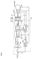
- Fig. 1 is a block diagram showing a configuration of a hybrid vehicle 100 as an example of the configuration on which the electric motor drive control system in accordance with an embodiment of the invention is mounted.
- hybrid vehicle 100 includes an engine 110, a power split mechanism 120, motor generators MG1 and MG2, a reduction gear 130, a driving shaft 140 and wheels (driving wheels) 150.
- Hybrid vehicle 100 further includes a DC voltage generating unit 10#, a smoothing capacitor C0, inverters 20 and 30, and a controller 50, for controlling driving of motor generators MG1 and MG2.
- Engine 110 is implemented, for example, by an internal combustion engine such as a gasoline engine or a diesel engine.
- a water temperature sensor 112 detecting temperature of cooling water is provided on engine 110.
- An output of water temperature sensor 112 is transmitted to controller 50.
- Power split mechanism 120 is formed to allow distribution of power generated by engine 110 to a path to driving shaft 140 and to a path to motor generator MG1.
- a planetary gear mechanism having three rotation shafts of a sun gear, a planetary gear and a ring gear may be used as the power split mechanism 120.
- the rotor of motor generator MG1 is connected to the sun gear
- the output shaft of engine 110 is connected to the planetary gear
- the output shaft 125 is connected to the ring gear.
- Output shaft 125 which is also connected to a rotation shaft of motor generator MG2, is connected to driving shaft 140 for driving rotation of driving wheels 150 through reduction gear 130.
- a reduction gear corresponding to the rotation shaft of motor generator MG2 may further be incorporated.
- Motor generator MG1 is formed to have functions of a motor and a generator, to operate as a generator driven by engine 110 and as a motor that can start the operation of engine 110.
- motor generator MG2 is incorporated in hybrid vehicle 100 for generating power to drive the vehicle, of which output is transmitted through output shaft 125 and reduction gear 130 to driving shaft 140. Further, motor generator MG2 is formed to have the functions of a motor and a generator, to generate an output torque in the direction opposite to the rotation of wheels 150, thereby to regenerate electric power.
- DC voltage generating unit 10# includes a battery B for driving the vehicle (hereinafter also referred to as "main battery B"), a smoothing capacitor C1, and a step-up/down converter 15.
- Main battery B corresponds to the "DC power source” of the present invention
- step-up/down converter 15 corresponds to the "converter” of the present invention.
- Nickel hydride or lithium ion secondary battery may be used as main battery B.
- main battery B implemented by a secondary battery is used as the "DC power source"
- an electric storage such as an electric double layer capacitor may be used in place of main battery B.
- a battery voltage Vb output by main battery B is detected by a voltage sensor 10, and a battery current Ib input to/output from main battery B is detected by a current sensor 11.
- a temperature sensor 12 is provided on main battery B. Temperature of main battery B, however, may vary locally. Therefore, temperature sensors 12 may be provided on a plurality of portions of main battery B. Battery voltage Vb, battery current Ib and battery temperature Tb detected by voltage sensor 10, current sensor 11 and temperature sensor 12 are output to controller 50.
- Smoothing capacitor C1 is connected between a ground line 5 and a power supply line 6. Between a positive electrode terminal of main battery B and power supply line 6 and between a negative electrode terminal of main battery B and ground line 5, relays (not shown) are provided, which are turned on when the vehicle is in operation and turned off when the operation of the vehicle stops.
- Step-up/down converter 15 (hereinafter also simply referred to as a converter) includes a reactor L1 and power semiconductor switching elements Q1 and Q2 (hereinafter referred to as "switching elements"), of which switching is controlled.
- Reactor L1 is connected between a connection node of switching elements Q1 and Q2 and power supply line 6.
- Smoothing capacitor C0 is connected between power supply line 7 and ground line 5.
- Switching elements Q1 and Q2 are connected in series between power supply line 7 and ground line 5. On/off of switching elements Q1 and Q2 is controlled by switching control signals S1 and S2 from controller 50.
- an IGBT Insulated Gate Bipolar Transistor
- a power MOS Metal Oxide Semiconductor
- a power bipolar transistor may be used as the switching element.
- Anti-parallel diodes D1 and D2 are arranged for switching elements Q1 and Q2.
- DC voltage sides of inverters 20 and 30 are connected to converter 15 through common ground line 5 and power supply line 7.
- power supply line 7 corresponds to the "DC power line” of the present invention.
- motor generators MG1 and MG2 correspond to the “electric motors” of the present invention
- inverters 20 and 30 correspond to the “inverters” of the present invention.
- Inverter 20 is formed of a U-phase arm 22, a V-phase arm 24 and a W-phase arm 26 provided in parallel between power supply line 7 and ground line 5.
- the arm of each phase is implemented by switching elements connected in series between power supply line 7 and ground line 5.
- U-phase arm 22 includes switching elements Q11 and Q12
- V-phase arm 24 includes switching elements Q 13 and Q 14
- W-phase arm 26 includes switching elements Q15 and Q16.
- anti-parallel diodes D11 to D16 are connected to switching elements Q11 to Q16, respectively. On/off of switching elements Q11 to Q16 is controlled by switching control signals S11 to S16 from controller 50, respectively.
- Motor generator MG1 includes a U-phase coil U1, a V-phase coil V1 and a W-phase coil W1, provided on a stator, and a rotor, not shown.
- U-phase coil U1, V-phase coil V1 and W-phase coil W1 have one end connected together at a neutral point N1, and have the other end connected to U-phase arm 22, V-phase arm 24 and W-phase arm 26 of inverter 20, respectively.
- Inverter 20 performs bi-directional power conversion between DC voltage generating unit 10# and motor generator MG1, through on/off control (switching control) of switching elements Q11 to Q16 in response to switching control signals S11 to S16 from controller 50.
- inverter 20 may convert the DC voltage received from power supply line 7 to a 3-phase AC voltage, and output the converted 3-phase AC voltage to motor generator MG1. Consequently, motor generator MG1 is driven to generate a designated torque. Further, in accordance with the switching control by controller 50, inverter 20 may convert the 3-phase AC voltage generated by motor generator MG1 receiving an output of engine 110 to a DC voltage and output the converted DC voltage to power supply line 7.
- Inverter 30 has a structure similar to inverter 20, and includes switching elements Q21 to Q26, of which on/off is controlled by switching control signals S21 to S26, and anti-parallel diodes D21 to D26.
- Motor generator MG2 has a structure similar to motor generator MG1, and includes a U-phase coil U2, a V-phase coil V2 and a W-phase coil W2 provided on a stator, and a rotor, not shown. Similar to motor generator MG1, U-phase coil U2, V-phase coil V2 and W-phase coil W2 have one end connected together at a neutral point N2, and have the other end connected to U-phase arm 32, V-phase arm 34 and W-phase arm 36 of inverter 30, respectively.
- Inverter 30 performs bi-directional power conversion between DC voltage generating unit 10# and motor generator MG2, through on/off control (switching control) of switching elements Q21 to Q26 in response to switching control signals S21 to S26 from controller 50.
- inverter 30 may convert the DC voltage received from power supply line 7 to a 3-phase AC voltage, and output the converted 3-phase AC voltage to motor generator MG2. Consequently, motor generator MG2 is driven to generate a designated torque. Further, in accordance with the switching control by controller 50, inverter 30 may convert the 3-phase AC voltage generated by motor generator MG2 receiving rotational force of wheel 150 at the time of regenerative braking of the vehicle to a DC voltage and output the converted DC voltage to power supply line 7.
- the regenerative braking here refers to braking with regeneration through a foot brake operation by a driver of the hybrid vehicle, or deceleration (or stopping acceleration) of the vehicle while regenerating power, by releasing the accelerator pedal during running, without operating the foot brake.
- Each of motor generators MG1 and MG2 is provided with a current sensor 27 and a rotation angle sensor (resolver) 28.
- a current sensor 27 As the sum of instantaneous values of 3-phase currents iu, iv and iw is zero, what is necessary is simply to arrange the current sensors 27 to detect motor currents of two phases only (for example, V-phase current iv and W-phase current iw), as shown in Fig. 1 .
- Rotation angle sensor 28 detects a rotation angle ⁇ of the rotor, not shown, of motor generators MG1 and MG2, and transmits the detected rotation angle ⁇ to controller 50.
- the number of rotations Nmt (angular velocity ⁇ ) of motor generators MG1 and MG2 may be calculated by controller 50.
- the term “number of rotations” refers to the number of rotations per unit time (typically, per one minute), or rotation speed, unless specified otherwise.
- Motor current MCRT(1) and rotor rotation angle ⁇ (1) of motor generator MG1 as well as motor current MCRT(2) and rotor rotation angle ⁇ (2) of motor generator MG2 detected by these sensors are input to controller 50. Further, controller 50 receives, as inputs, a torque command value Tqcom(1) and a control signal RGE(1) representing a regenerative operation of motor generator MG1 as well as a torque command value Tqcom(2) and a control signal RGE(2) representing a regenerative operation of motor generator MG2, as motor commands.
- Controller 50 implemented by an electronic control unit (ECU) includes a microcomputer (not shown), an RAM (Random Access Memory) 51 and an ROM (Read Only Memory) 52, and generates, in accordance with a prescribed program processing, switching control signals S1 and S2 (converter 15), S11 to S16 (inverter 20) and S21 to S26 (inverter 30) for switching control of converter 15 and inverters 20 and 30, such that motor generators MG1 and MG2 operate in accordance with a motor command input from the electronic control unit (ECU) of a higher order.
- ECU electronice control unit
- controller 50 has a function of limiting, as needed, the power consumption and the power generation (regenerative power) of motor generators MG1 and MG2, so that excessive charge or excessive discharge of DC power source B can be avoided.
- controller 50 sets a voltage command value VH# (hereinafter also referred to as "system voltage command value VH#”) of a DC voltage VH (the DC voltage corresponding to the DC side voltage of inverters 20 and 30, hereinafter also referred to as "system voltage VH”) based on the state of operations of motor generators MG1 and MG2, and based on the system voltage command value VH# and the detected value of a voltage sensor 13, generates switching control signals S1 and S2 such that the output voltage of converter 15 becomes equal to the system voltage command value VH#.
- system voltage command value VH# the DC voltage corresponding to the DC side voltage of inverters 20 and 30, hereinafter also referred to as "system voltage VH”
- converter 15 commonly supplies the system voltage VH obtained by boosting the DC voltage (battery voltage) Vb supplied from main battery B to inverters 20 and 30. More specifically, in response to switching control signals S1 and S2 from controller 50, duty ratio (ratio of on period) of switching elements Q1 and Q2 is set, and the voltage-up ratio is in correspondence with the duty ratio.
- converter 15 lowers the DC voltage (system voltage) supplied from inverters 20, 30 through smoothing capacitor C0 and charges main battery B.
- DC voltage system voltage
- controller 50 in response to switching control signals S1 and S2 from controller 50, a period in which only the switching element Q1 is on and a period in which both switching elements Q1 and Q2 are off are provided alternately, and the voltage-down ratio is in correspondence with the duty ratio of the on-period mentioned above.
- Smoothing capacitor C0 smoothes the DC voltage (system voltage) from converter 15, and supplies the smoothed DC voltage to inverters 20 and 30.
- Voltage sensor 13 detects the voltage at opposite ends of smoothing capacitor C0, that is, the system voltage VH, and outputs the detected value to controller 50.
- Inverter 30 drives motor generator MG2 such that a torque in accordance with the torque command value Tqcom(2) is output, through on/off operations (switching operations) of switching elements Q21 to Q26 in response to switching control signals S21 to S26 from controller 50.
- the torque command value of motor generator MG2 is set to a negative value (Tqcom(2) ⁇ 0).
- inverter 30 converts the AC voltage generated by motor generator MG2 to a DC voltage by a switching operation in response to switching control signals S21 to S26, and supplies the converted DC voltage (system voltage) through smoothing capacitor C0 to converter 15.
- inverter 20 converts power so that motor generator MG1 operates in accordance with the command value, by on/off control of switching elements Q11 to Q 16 in accordance with switching control signals S11 to S16 from controller 50.
- Fig. 2 illustrates the inverter control method used in the electric motor drive control system shown in Fig. 1 .
- Sinusoidal PWM (pulse width modulation) control is used as general PWM control, in which on/off of a switching element at the arm of each phase is controlled in accordance with a comparison in voltage between a sinusoidal voltage command value and a carrier wave (typically, a triangular wave).
- a carrier wave typically, a triangular wave.
- the duty ratio is controlled such that the fundamental wave component thereof comes to be a sinusoidal wave within a prescribed period.
- the amplitude of fundamental wave component can be increased only to 0.61 times that of the DC side voltage (that is, system voltage VH) of the inverter.
- one pulse of rectangular wave having the ratio of high-level to low-level period of 1:1 1 is applied to motor generator MG within the prescribed time period mentioned above.
- the modulation factor can be increased to 0.78.
- PWM control similar to the sinusoidal PWM control is performed with the carrier wave distorted to have smaller amplitude.
- the fundamental wave component can be distorted, and the modulation factor can be improved to the range of 0.61 to 0.78.
- motor generator MG (generally representing MG1 and MG2, same in the following), when the number of rotations and/or torque increases, back electromotive force increases and induction voltage becomes higher, so that necessary voltage increases. Accordingly, it becomes necessary to set the output voltage (system voltage VH) of converter 15 to be higher than the necessary voltage.
- boosting of converter 15 is limited, and there is an upper limit (that is, maximum system voltage) in the output voltage thereof.
- the maximum torque control through sinusoidal PWM control or overmodulation PWM control is applied, and the output torque is adjusted to the torque command value Tqcom by the motor current control in accordance with the vector control.
- switching loss at the inverter depends on the number of switching per unit time. Therefore, under such same conditions, switching loss is the largest in sinusoidal PWM control, smallest in the rectangular wave voltage control, and the middle in overmodulation PWM control.
- Fig. 3 shows a control block in accordance with the sinusoidal PWM control method and overmodulation PWM control method.
- the electric motor control in accordance with the block diagram of Fig. 3 is implemented by executing a program stored in advance in controller 50 in a prescribed period.
- PWM control block 200 includes a current command generating unit 210, coordinate converting units 220 and 250, a rotation number calculating unit 230, a PI operating unit 240, and a PWM signal generating unit 260.
- Current command generating unit 210 generates a d-axis current command value Idcom and a q-axis current command value Iqcom in accordance with a torque command value Tqcom (generally representing Tqcom(1) and Tqcom(2), same in the following), with reference to a map or the like formed beforehand.
- Tqcom torque command value
- Coordinate converting unit 220 calculates the d-axis current iq and q-axis current iq based on V phase current iv and W phase current iw detected by current sensor 27, by coordinate conversion (three-phase ⁇ two-phase) using rotation angle ⁇ of motor generator MG detected by rotation angle sensor 28. Based on the output from rotation angle sensor 28, rotation number calculating unit 230 calculates the number of rotations Nmt (or rotational angular velocity ⁇ ) of motor generator MG.
- PI operating unit 240 calculates control deviation by PI operation with a prescribed gain, on each of d-axis current deviation ⁇ Id and q-axis current deviation ⁇ Iq, and generates a d-axis voltage command value Vd# and a q-axis voltage command value Vq#, in accordance with the control deviation.
- Command converting unit 250 converts d-axis voltage command value Vd# and q-axis voltage command value Vq# to voltage command values Vu, Vv and Vw of respective ones of U, V and W phases, through voltage conversion (two-phase ⁇ three-phase), using rotation angle ⁇ of motor generator MG.
- System voltage VH is also reflected on the conversion from d-axis and q-axis voltage command values Vd# and Vq# to voltage command values Vu, Vv and Vw of respective phases.
- PWM signal generating unit 260 generates switching control signals S 11 to S 16 (S21 to S26) shown in Fig. 1 , based on the comparison between a prescribed carrier wave and the voltage command values Vu, Vv and Vw of respective phases.
- inverter 20 (30) As the switching of inverter 20 (30) is controlled in accordance with switching control signals S11 to S16 (S21 to S26) generated by PWM control block 200, an AC voltage for outputting a torque in accordance with the torque command value Tqcom is applied to motor generator MG.
- switching control signals S11 to S16 S21 to S26
- Tqcom torque command value
- the carrier wave used at the time of PWM at PWM signal generating unit 260 is switched from the general one used when sinusoidal wave PWM control method is applied.
- a voltage command value generating unit 300 a voltage command amplitude calculating unit 320, a modulation factor calculating unit 330 and a control method selecting unit 340 are further provided, in order to select the control method in accordance with the required modulation factor.
- Voltage command value generating unit 300 sets the voltage command value VH# of system voltage VH in accordance with the state of operation (torque, number of rotations) of motor generator MG1, MG2.
- the voltage command value VH# will be described in detail later.
- Voltage command amplitude calculating unit 320 calculates a line voltage amplitude Vamp in accordance with equations (1) and (2) below, using d-axis voltage command value Vd# and q-axis voltage command value Vq# generated by PI calculating unit 240, as well as a voltage phase ⁇ (voltage phase with d-axis being the reference).
- Modulation factor calculating unit 330 calculates the actual modulation factor in accordance with equation (3) below, from the line voltage amplitude Vamp calculated by voltage command amplitude calculating unit 320 and from the voltage command value VH# of system voltage.
- Kmd Vamp / VH#
- Control method selecting unit 340 selects a method of control that can attain the modulation factor Kmd calculated by modulation factor calculating unit 330 from among sinusoidal PWM control, overmodulation PWM control and rectangular wave voltage control.
- PWM signal generating unit 350 Based on the detected values of battery voltage Vb and system voltage VH detected by voltage sensors 10 and 13, PWM signal generating unit 350 generates switching control signals S1 and S2 in accordance with the prescribed PWM control method such that the output voltage of converter 15 becomes equal to the voltage command value VH#.
- Fig. 4 is a control block diagram for the rectangular wave voltage control. As described above, the rectangular wave voltage control is selected when modulation factor Kmd calculated by modulation factor calculating unit 330 cannot be realized by overmodulation PWM control.
- the rectangular wave voltage control in accordance with the block diagram of Fig. 4 is also implemented by executing a program stored in advance in controller 50 at a prescribed period.
- rectangular wave voltage control block 400 includes a power calculating unit 410, a torque calculating unit 420, a PI calculating unit 430, a rectangular wave generator 440, and a signal generating unit 450.
- Power calculating unit 410 calculates the motor supply power Pmt in accordance with equation (4), from currents of respective phases obtained by V-phase current iv and W-phase current iw of current sensor 27 and from voltages Vu, Vv and Vw of respective phases (U-phase, V-phase, W-phase).
- Pmt iu • Vu + iv • Vv + iw • Vw
- Torque calculating unit 420 calculates a torque estimation value Tq in accordance with equation (5) below, from motor power Pmt obtained by power calculating unit 410 and angular velocity ⁇ calculated from rotation angle ⁇ of motor generator MG detected by rotation angle sensor 28.
- Tq Pmt / ⁇
- PI calculating unit 430 performs a PI operation with a prescribed gain on torque deviation ⁇ Tq to find a control deviation, and in accordance with the obtained control deviation, sets the phase ⁇ v of rectangular wave voltage.
- voltage phase ⁇ v is controlled such that the voltage phase is advanced when the torque is insufficient, and the voltage phase is retarded when the torque is excessive.
- voltage phase ⁇ v is controlled such that the voltage phase is retarded when the torque is insufficient, and the voltage phase is advanced when the torque is excessive.
- Rectangular wave generator 440 generates voltage command values (rectangular wave pulses) Vu, Vv and Vw of respective phases, in accordance with the voltage phase ⁇ v set by PI calculating unit 430.
- Signal generating unit 450 generates switching control signals S11 to S16 (S21 to S26) in accordance with the voltage command values Vu, Vv and Vw of respective phases.
- inverter 20 (30) performs the switching operation in accordance with switching control signals S11 to S16 (S21 to S26), rectangular wave pulses in accordance with the voltage phase ⁇ v are applied as voltages of respective phases of the motor.
- Fig. 5 is a flowchart representing the setting of system voltage command value in accordance with an embodiment of the present invention.
- controller 50 sets torque command values Tqcom(1) and Tqcom(2) in accordance with output request (number of rotations x torque) to motor generator MG1, MG2, dependent on the vehicle state (vehicle speed, pedal operation and the like).
- controller 50 calculates the necessary voltage Vmg1 that corresponds to the induction voltage of motor generator MG1, in accordance with the number of rotations of motor generator MG1 and the torque command value Tqcom(1).
- controller 50 calculates the necessary voltage Vmg2 that corresponds to the induction voltage of motor generator MG2, in accordance with the number of rotations of motor generator MG2 and the torque command value Tqcom(2).
- the necessary voltages Vmg1 and Vmg2 are set relatively higher.
- calculation of necessary voltages Vmg1 and Vmg2 at steps S110 and S120 may be executed by making a reference to a map reflecting the characteristic shown in Fig. 6 for each of motor generators MG1 and MG2, using torque command value Tqcom and number of rotations Nmt as arguments.
- controller 50 calculates the minimum necessary voltage VHmin as the maximum value of necessary voltages Vmg1 for MG1 and Vmg2 for MG2 calculated at steps S110 and S120, respectively. Specifically, the minimum necessary voltage VHmin is set to be higher than the induction voltages of motor generators MG1 and MG2.
- controller 50 sets a plurality of candidate voltages VH(1) to VH(n) in a voltage range from the minimum necessary voltage VHmin found at step S130 to the maximum output voltage VHmax (hereinafter the voltage range will be also be referred to as the "candidate voltage range") of converter 15.
- n is an integer not smaller than 2.
- the number and/or voltage interval of candidate voltages VH(1) to VH(n) may be fixed or variably set in accordance with the state of operations of motor generators MG1 and MG2. Further, the voltage interval of candidate voltages VH(1) to VH(n) is not necessarily limited to an equal interval.
- controller 50 estimates a power loss (battery loss) Plb at main battery B with candidate voltage VH(i).
- controller 50 estimates power loss (converter loss) Plcv with candidate voltage VH(i).
- controller 50 estimates power losses (inverter losses) Pliv1 and Pliv2 at inverters 20 and 30 with candidate voltage VH(i).
- controller 50 estimates power losses (MG losses) Plmg1 and Plmg2 at motor generators MG1 and MG2 with candidate voltage VH(i).
- Controller 50 calculates total power loss Plt as the total sum of battery loss Plb, converter loss Plcv, inverter losses Pliv1, Pliv2 and MG losses Plmg1, Plmg2 estimated at steps S150, S152, S 154 and S156, respectively (S160). Then, controller 50 calculates the total sum Plt of power losses in the whole system for each of candidate voltages VH(1) to VH(n), by the repetition process of steps S162 and S165.
- controller 50 establishes the candidate voltage VH(j) with which the total sum of power losses Plt becomes the smallest, from candidate voltages VH(1) to VH(n).
- controller 50 calculates the optimal voltage VHopt based on the candidate voltage VH(j).
- the candidate voltage VH(j) may directly be used as the optimal voltage VHopt, or the optimal voltage VHopt may be calculated by interpolation of candidate voltage VH(j) and a neighboring candidate voltage VH(j-1) or VH(j+1).
- the system voltage command value VH# is set so that the system voltage VH that minimizes total power loss of the electric motor control system as a whole is attained.
- Battery loss Plb mainly comes from Joule loss caused by internal resistance, and is represented as Ib•r 2 , using internal resistance value r and battery current Ib.
- battery current Ib is the average current (DC component) Ibave with ripple current (AC component) ⁇ Ibr superposed thereon.
- the ripple current ⁇ Ibr increases in accordance with a voltage difference
- battery loss Plb is represented by the sum of power loss Plb1 in proportion to the square of average current (DC) Ibave and power loss Plb2 in proportion to the square of AC power component ⁇ Ibr.
- the power loss Plb2 derived from the ripple current increases as the voltage difference
- battery loss Plb can be estimated based on the average battery current (DC) Ibave, that is, based on the state of operation of MG1, MG2 (torque x number of rotations) and the voltage difference
- DC battery current
- the input/output power to/from the battery represented as a product between the average current Ibave and battery voltage Vb corresponds to the total sum of power consumed or generated by each motor generator MG, and does not change dependent on the system voltage VH. Therefore, as the battery loss Plb to be evaluated in establishing the optimal value of voltage command value VH#, Plb2 should mainly be taken into consideration.
- the change in battery loss Plb with respect to the candidate voltage VH(i) may be estimated.
- the loss at converter 15 is mainly the sum of losses at switching elements Q1 and Q2 and loss at reactor L1, each of which becomes smaller when the current passing through the converter (that is, battery current Ib) becomes smaller and the system voltage VH becomes lower.
- the ripple current ⁇ Ibr increases, loss that depends on the square of the current increases, and hence, the voltage difference
- converter loss Plcv is basically in accordance with the square of battery current Ib. Therefore, as shown in Fig. 9 , converter loss Plcv is basically in proportion to the square of average current Ibave of battery current Ib, and it increases as the voltage difference
- converter loss Plcv can also be estimated based on the average battery current Ibave, that is, based on the state of operation of MG1, MG2 (torque x number of rotations) and the voltage difference
- the average battery current Ibave does not change dependent on the system voltage VH. Therefore, as regards the converter loss Plcv to be evaluated to establish the optimal value of voltage command value VH#, by forming, in advance, a map reflecting the characteristic shown in Fig. 9 with the voltage difference
- the inverter loss at inverters 20 and 30 mainly comes from on-loss and switching loss of the switching elements, and it becomes smaller as the current flowing through the switching elements is smaller and the system voltage is lower.
- the method of controlling electric motor by inverters 20 and 30 is such that in a range 500 of low number of rotations, sinusoidal PWM control is selected, in a range 510 where the number of rotations is increased and the larger modulation factor is required, overmodulation PWM control is selected, and in a range 520 of higher number of rotations, rectangular wave control is effected.
- control method is switched from sinusoidal PWM control to overmodulation PWM control as the number of rotations of MG increases and attains close to N1, and switched from overmodulation PWM control to rectangular wave voltage control as the number of rotations of MG further increases and attains close to N2.
- inverter power loss Pliv1 in the range where the number of rotations of MG is from N0 to N1, that is, where sinusoidal PWM control is applied, the switching voltage of each switching element increases as the system voltage VH increases as long as the same torque (T1) is output, and therefore, switching loss increases. Accordingly, inverter loss Pliv1 (or Pliv2) increases.
- the control method is switched from sinusoidal PWM control to overmodulation PWM control in which the number of switching operations per unit time is relatively small, whereby inverter loss Pliv1 (or Pliv2) decreases, though the system voltage VH further increases as the MG rotation number increases.
- inverter loss Pliv1 (or Pliv2) gradually increases as the switching loss at each switching element increases in accordance with the increase in system voltage VH. Further, in a range where the system voltage attains to the maximum output voltage VHmax of the converter and rectangular wave voltage control is applied, it becomes necessary to lower inverter efficiency through field weakening control to suppress induction voltage at motor generator MG. Therefore, though the number of switching operations per unit time decreases, inverter loss Pliv1 (or Pliv2) gradually increases.
- the MG loss in motor generators MG1 and MG2 is a sum of copper loss caused by the current flowing through coils of respective phases, and iron loss generated by flux change at the iron core portion. Therefore, MG loss is smaller as the current flowing through the coils of respective phases is smaller.
- MG loss at motor generators MG1 and MG2 may be estimated based on the state of operation (number of rotations and torque) of the motor.
- Fig.11 shows relation between the system voltage and the torque, and the sum of power losses Pliv1 + Plmg1 of inverter 20 and motor generator MG1 (and the sum of power losses Pliv2 + Plmg2 of inverter 30 and motor generator MG2), with a certain constant number of rotations.
- Fig. 11 shows that a map for estimating inverter loss and MG loss can be set in advance, based on the number of rotations and the torque (torque command value) of motor generator MG and the system voltage, in consideration of the difference between each of the applied control methods described above.
- the inverter loss can be estimated by setting in advance the method of control to be selected in correspondence with the state of operation (that is, number of rotations and torque command value) of motor generator MG.
- a battery loss estimating unit 550 estimating battery loss Plb
- an inverter loss estimating unit 570 estimating inverter losses Pinv1 and Pinv2
- an MG loss estimating unit 580 estimating MG losses Plmg1 and Plmg2 at motor generators MG1 and MG2, mainly using as an argument at least one of the rotation number/torque (torque command value Tqcom(1)) of motor generator MG1, the rotation number/torque (torque command value Tqcom(2)) of motor generator MG2 and the system voltage VH.
- a map 555 based on the characteristic shown in Fig. 8 may be formed in advance in battery loss estimating unit 550, and by making a reference to the map 555, based on the state of operations of motor generators MG1 and MG2 as well as the candidate voltage VH(i) of system voltage VH, battery loss Plb at that time can be estimated.
- a map 565 based on the characteristic shown in Fig. 9 may be formed in advance in converter loss estimating unit 560, and by making a reference to the map 565, based on the state of operations of motor generators MG1 and MG2 as well as the candidate voltage VH(i) of system voltage VH, converter loss Plcv at that time can be estimated.
- or the system voltage VH (candidate voltage VH(i)) as the argument may be formed.
- inverter loss estimating unit 570 and MG loss estimating unit 580 can be formed integrally, for estimating the sum of inverter loss and MG loss Plmg1 + Pliv1 (or Plmg2 + pliv2), using the state of operations of motor generators MG1 and MG2 as well as the candidate voltage VH(i) as arguments.
- inverter loss estimating unit 570 may be formed to estimate inverter loss Pliv1 (Pliv2) further reflecting the control methods described above.
- an inverter loss estimating unit 570# is provided independent from MG loss estimating unit 580.
- MG loss estimating unit 580 is formed by incorporating a map 585 based on estimation of copper loss and iron loss, using the state of operation (rotation number/torque) of motor generator MG1 (MG2) as an argument.
- MG loss estimating unit 580 estimates MG losses Plmg1 and Plmg2, based on the state of operation (rotation number/torque) of motor generator MG1 (MG2).
- Inverter loss estimating unit 570# includes maps 575a, 575b and 575c provided corresponding to respective control methods, as well as an output switching unit 576.
- Map 575a is formed to allow estimation of inverter loss Pliv1 (Pliv2) mainly reflecting switching loss at the switching elements, using the state of operation (rotation number/torque) of the corresponding motor generator MG1 (MG2) and the system voltage (candidate voltage VH(i)) as the arguments, under sinusoidal PWM control.
- map 575b is formed to allow estimation of inverter loss Pliv1 (Pliv2) mainly reflecting switching loss at the switching elements, using the state of operation (rotation number/torque) of the corresponding motor generator MG1 (MG2) and the system voltage (candidate voltage VH(i)) as the arguments, under overmodulation PWM control.
- Pliv2 inverter loss
- MG1 motor generator
- VH(i) system voltage
- map 575c is formed to allow estimation of inverter loss Pliv1 (Pliv2) mainly reflecting switching loss at the switching elements, using the state of operation (rotation number/torque) of the corresponding motor generator MG1 (MG2) and the system voltage (candidate voltage VH(i)) as the arguments, under rectangular wave voltage control.
- Output switching unit 576 selects one map from maps 575a, 575b and 575c, in accordance with the method of control selected at present, in accordance with the output of control method selecting unit 340. Accordingly, based on the reference of the map selected by output switching unit 576, inverter loss Pliv1 (Pliv2) can be estimated.
- the system voltage VH can be set to an optimal voltage that minimizes the total sum of power loss in the system as a whole, based on power loss estimation of each of the DC power source (battery), converter, inverters and motor generators MG.
- the DC power source battery
- converter inverters
- motor generators MG motor generators
- the loss in electric motor drive control system as a whole with respect to variation in system voltage VH can more accurately be estimated.
- setting of system voltage VH can further be optimized, and the overall efficiency of the electric motor drive control system can more reliably be improved.
- step S 150 of Fig. 5 or battery loss estimating unit 550 of Fig. 12 corresponds to the "first loss estimating unit” of the present invention
- step S152 of Fig. 5 or converter loss estimating unit 560 of Fig. 12 corresponds to the "second loss estimating unit” of the present invention
- step S 154 of Fig. 5 or inverter loss estimating unit 570 of Fig. 12 corresponds to the "third loss estimating unit” of the present invention
- step S 156 of Fig. 5 or MG loss estimating unit 580 of Fig. 12 corresponds to the "fourth loss estimating unit” of the present invention
- steps S 130 and S160 to S 180 of Fig. 5 or voltage command value generating unit 300 of Fig. 3 correspond to the "voltage command value generating unit" of the present invention.
- a control structure may be adopted in which, among the battery loss, converter loss, inverter loss and MG loss, only the power loss or losses that significantly vary dependent on the variation of system voltage VH may be estimated and the total sum thereof may be calculated.
- the setting of system voltage VH can be set optimally while burden of calculation is alleviated.
- the electric motor drive control system mounted on a hybrid vehicle has been described as a representative. Application of the present invention, however, is not limited thereto. Specifically, the motor driving system in accordance with the present invention may be applied to an electric motor drive control system mounted on a vehicle other than the hybrid vehicle as represented by an electric vehicle. Further, the present invention is applicable to any electric motor drive control system including a converter capable of variably controlling a DC voltage, without any limitation on the type or number of motor generators (or electric motors/generators) of which driving is controlled or on the load driven by the motor generator (electric motor).
Applications Claiming Priority (2)
| Application Number | Priority Date | Filing Date | Title |
|---|---|---|---|
| JP2006150110A JP5109290B2 (ja) | 2006-05-30 | 2006-05-30 | 電動機駆動制御システムおよびその制御方法 |
| PCT/JP2007/060944 WO2007139126A1 (ja) | 2006-05-30 | 2007-05-23 | 電動機駆動制御システムおよびその制御方法 |
Publications (3)
| Publication Number | Publication Date |
|---|---|
| EP2023482A1 true EP2023482A1 (de) | 2009-02-11 |
| EP2023482A4 EP2023482A4 (de) | 2017-07-19 |
| EP2023482B1 EP2023482B1 (de) | 2020-04-22 |
Family
ID=38778644
Family Applications (1)
| Application Number | Title | Priority Date | Filing Date |
|---|---|---|---|
| EP07744363.8A Active EP2023482B1 (de) | 2006-05-30 | 2007-05-23 | Motorantriebssteuersystem und steuerverfahren dafür |
Country Status (6)
| Country | Link |
|---|---|
| US (1) | US7701156B2 (de) |
| EP (1) | EP2023482B1 (de) |
| JP (1) | JP5109290B2 (de) |
| KR (1) | KR101021256B1 (de) |
| CN (1) | CN101461130B (de) |
| WO (1) | WO2007139126A1 (de) |
Cited By (4)
| Publication number | Priority date | Publication date | Assignee | Title |
|---|---|---|---|---|
| EP2372894A3 (de) * | 2010-03-31 | 2015-05-20 | Kabushiki Kaisha Toyota Jidoshokki | Umwandlungssystem von Direktstrom in dreiphasigen Wechselstrom |
| US9762152B2 (en) | 2011-09-06 | 2017-09-12 | Toyota Jidosha Kabushiki Kaisha | Motor control system for executing drive control of an alternating-current motor |
| CN107303827A (zh) * | 2016-04-18 | 2017-10-31 | 现代自动车株式会社 | 用于控制车辆的转换器的方法和系统 |
| US10399442B2 (en) | 2016-03-16 | 2019-09-03 | Toyota Jidosha Kabushiki Kaisha | Solar battery system |
Families Citing this family (82)
| Publication number | Priority date | Publication date | Assignee | Title |
|---|---|---|---|---|
| JPWO2005093942A1 (ja) * | 2004-03-24 | 2007-08-30 | 三菱電機株式会社 | 永久磁石式同期モータの制御装置 |
| DE102005044174A1 (de) * | 2005-09-16 | 2007-03-22 | Bayerische Motoren Werke Ag | Abstandsbezogenes Fahrgeschwindigkeitsregelsystem |
| JP4407679B2 (ja) * | 2006-08-25 | 2010-02-03 | マツダ株式会社 | ハイブリッド車両の制御装置 |
| JP4984236B2 (ja) * | 2007-04-17 | 2012-07-25 | 株式会社デンソー | 電気自動車の制御装置 |
| JP4274271B2 (ja) * | 2007-07-26 | 2009-06-03 | トヨタ自動車株式会社 | 電圧変換装置 |
| TW200909822A (en) * | 2007-08-17 | 2009-03-01 | Delta Electronics Inc | Measuring apparatus for power loss of magnetic device |
| JP2009142117A (ja) * | 2007-12-10 | 2009-06-25 | Ihi Corp | モータ電力供給装置とこれを生産する方法 |
| JP4353304B2 (ja) * | 2008-02-19 | 2009-10-28 | トヨタ自動車株式会社 | モータ駆動制御装置 |
| JP4453765B2 (ja) | 2008-02-26 | 2010-04-21 | トヨタ自動車株式会社 | ハイブリッド車およびその制御方法 |
| JP4424427B2 (ja) | 2008-03-18 | 2010-03-03 | トヨタ自動車株式会社 | 車両の制御装置および制御方法 |
| JP2009227080A (ja) * | 2008-03-21 | 2009-10-08 | Toyota Motor Corp | 動力出力装置やこれを備える車両および駆動装置並びにこれらの制御方法 |
| US8179705B2 (en) * | 2008-05-27 | 2012-05-15 | Power-One, Inc. | Apparatus and method of optimizing power system efficiency using a power loss model |
| JP5217741B2 (ja) * | 2008-07-31 | 2013-06-19 | トヨタ自動車株式会社 | システム作動制御装置 |
| JP2010089719A (ja) * | 2008-10-10 | 2010-04-22 | Toyota Motor Corp | ハイブリッド車両の電源システム |
| JP5065223B2 (ja) * | 2008-10-17 | 2012-10-31 | トヨタ自動車株式会社 | 車両制御システム |
| JP4329880B1 (ja) * | 2009-01-14 | 2009-09-09 | トヨタ自動車株式会社 | 交流電動機の制御装置および電動車両 |
| JP5438328B2 (ja) * | 2009-01-26 | 2014-03-12 | トヨタ自動車株式会社 | 車両のモータ制御システム |
| FR2944166B1 (fr) * | 2009-04-03 | 2011-03-18 | Sagem Defense Securite | Circuit d'alimentation d'un moteur et organe de commande de vol equipe d'un tel circuit |
| JP5526975B2 (ja) * | 2009-05-13 | 2014-06-18 | 株式会社安川電機 | 電動機の制御装置及びその制御方法 |
| US8575875B2 (en) * | 2009-05-27 | 2013-11-05 | Toyota Jidosha Kabushiki Kaisha | Control device for voltage converter, vehicle equipped with the same, and control method for voltage converter |
| CN102342017B (zh) | 2009-06-22 | 2014-01-08 | 爱信艾达株式会社 | 电机驱动装置的控制装置 |
| JP5493568B2 (ja) * | 2009-08-06 | 2014-05-14 | 株式会社デンソー | 電動機駆動装置及び電動機駆動装置の制御方法ならびに電動装置 |
| JP5297953B2 (ja) | 2009-09-08 | 2013-09-25 | トヨタ自動車株式会社 | 電動車両の電動機駆動システム |
| US8373372B2 (en) * | 2009-09-25 | 2013-02-12 | Ut-Battelle, Llc | Electrical motor/generator drive apparatus and method |
| JP4912516B2 (ja) * | 2009-12-08 | 2012-04-11 | 三菱電機株式会社 | 電力変換装置 |
| JP5036918B2 (ja) * | 2010-03-26 | 2012-09-26 | 三菱電機株式会社 | 電力変換装置 |
| WO2011132269A1 (ja) * | 2010-04-21 | 2011-10-27 | トヨタ自動車株式会社 | モータ駆動システムのための制御装置およびそれを搭載した車両 |
| JP5549864B2 (ja) * | 2010-06-15 | 2014-07-16 | 株式会社Ihi | 同一負荷パターンを有する装置の省電力駆動装置及び方法 |
| CN102893512B (zh) * | 2010-06-15 | 2015-09-09 | 株式会社Ihi | 具有相同负载模式的装置的省电力驱动装置及方法 |
| CN103141022B (zh) * | 2010-09-24 | 2015-09-16 | 日产自动车株式会社 | 逆变器控制装置和逆变器控制方法 |
| EP2671772B1 (de) * | 2011-02-03 | 2020-06-17 | Toyota Jidosha Kabushiki Kaisha | Hybridfahrzeug und steuerungsverfahren dafür |
| FR2975242B1 (fr) * | 2011-05-13 | 2013-04-26 | Michelin Soc Tech | Dispositif et procede de gestion du freinage electrique d'un vehicule |
| JP5172992B2 (ja) * | 2011-06-02 | 2013-03-27 | ファナック株式会社 | 直流変換部の最大出力計算部を備えたモータ駆動装置 |
| EP2728739A4 (de) * | 2011-06-30 | 2016-06-29 | Toyota Motor Co Ltd | Motoransteuerungsvorrichtung, fahrzeug damit und verfahren zur steuerung einer motoransteuerungsvorrichtung |
| JP2013034315A (ja) * | 2011-08-02 | 2013-02-14 | Fuji Electric Co Ltd | インバータの制御装置 |
| JP5893876B2 (ja) * | 2011-09-13 | 2016-03-23 | トヨタ自動車株式会社 | モータ制御システム |
| JP5781875B2 (ja) * | 2011-09-14 | 2015-09-24 | トヨタ自動車株式会社 | 回転電機制御システム |
| US8816627B2 (en) * | 2011-11-10 | 2014-08-26 | Mitsubishi Electric Research Laboratories, Inc. | Energy efficient motion control system |
| KR101283892B1 (ko) * | 2011-12-07 | 2013-07-08 | 기아자동차주식회사 | 친환경 차량에서 dc-dc컨버터 제어장치 및 방법 |
| JP6024209B2 (ja) * | 2012-05-29 | 2016-11-09 | 株式会社豊田自動織機 | バッテリの充電器制御システム |
| JP5972060B2 (ja) * | 2012-06-15 | 2016-08-17 | 東芝三菱電機産業システム株式会社 | ドライブシステムの制御装置 |
| FR2994899B1 (fr) * | 2012-08-29 | 2014-09-12 | Renault Sa | Procede de pilotage d'une machine electrique limitant les pertes energetiques |
| US20140121867A1 (en) * | 2012-11-01 | 2014-05-01 | GM Global Technology Operations LLC | Method of controlling a hybrid powertrain with multiple electric motors to reduce electrical power losses and hybrid powertrain configured for same |
| DE112012007127T5 (de) | 2012-11-13 | 2015-08-06 | Toyota Jidosha Kabushiki Kaisha | Aufwärtswandler-Steuerungsvorrichtung |
| JP5930064B2 (ja) | 2012-11-13 | 2016-06-08 | トヨタ自動車株式会社 | 昇圧コンバータの制御装置 |
| JP2014121215A (ja) * | 2012-12-18 | 2014-06-30 | Honda Motor Co Ltd | 負荷駆動制御装置 |
| JP2014128052A (ja) * | 2012-12-25 | 2014-07-07 | Toyota Motor Corp | 車両の制御装置 |
| JP5955761B2 (ja) * | 2012-12-25 | 2016-07-20 | トヨタ自動車株式会社 | 車両の制御装置 |
| TWI509941B (zh) * | 2013-06-05 | 2015-11-21 | Universal Scient Ind Shanghai | 電壓調節器、其運作方法以及電壓調節系統 |
| JP2015014278A (ja) * | 2013-07-08 | 2015-01-22 | ヤマハ発動機株式会社 | 始動発電機及びその制御方法 |
| JP6119475B2 (ja) * | 2013-07-15 | 2017-04-26 | 株式会社ジェイテクト | 車載用モータ制御装置 |
| CN104333291B (zh) * | 2013-07-22 | 2017-08-04 | 西门子公司 | 电机驱动控制装置及控制方法 |
| US9484733B1 (en) * | 2013-09-11 | 2016-11-01 | Western Digital Technologies, Inc. | Power control module for data storage device |
| JP6084914B2 (ja) * | 2013-09-24 | 2017-02-22 | トヨタ自動車株式会社 | 電力供給システム |
| KR101451787B1 (ko) * | 2014-06-19 | 2014-10-21 | 국방과학연구소 | 전기추진 차량의 고효율 전력변환 제어방법 |
| US9783185B2 (en) | 2014-08-19 | 2017-10-10 | General Electric Company | Vehicle propulsion system having an energy storage system and optimized method of controlling operation thereof |
| US9399407B2 (en) * | 2014-08-19 | 2016-07-26 | General Electric Company | Vehicle propulsion system having an energy storage system and optimized method of controlling operation thereof |
| US9878632B2 (en) | 2014-08-19 | 2018-01-30 | General Electric Company | Vehicle propulsion system having an energy storage system and optimized method of controlling operation thereof |
| US9889752B2 (en) | 2014-08-19 | 2018-02-13 | General Electric Company | Vehicle propulsion system having an energy storage system and optimized method of controlling operation thereof |
| KR102227848B1 (ko) * | 2014-10-23 | 2021-03-15 | 현대모비스 주식회사 | 하이브리드 전기 차량의 구동 시스템 및 이 시스템의 pwm 캐리어 신호의 위상 제어 방법 |
| EP3043467A1 (de) * | 2015-01-12 | 2016-07-13 | Siemens Aktiengesellschaft | Regelung einer Antriebsvorrichtung |
| JP6406108B2 (ja) | 2015-04-15 | 2018-10-17 | 株式会社デンソー | モータ制御システムの制御装置 |
| DE112015007090T5 (de) * | 2015-11-04 | 2018-07-26 | Mitsubishi Electric Corporation | Fahrzeugmotor-Steuervorrichtung und Fahrzeugmotor-Steuerverfahren |
| JP6080996B1 (ja) * | 2016-03-01 | 2017-02-15 | 三菱電機株式会社 | 電動機駆動システム |
| JP6143905B1 (ja) | 2016-03-08 | 2017-06-07 | 三菱電機株式会社 | 回転電機駆動装置の制御装置 |
| JP6451692B2 (ja) * | 2016-05-13 | 2019-01-16 | トヨタ自動車株式会社 | 自動車 |
| JP2018014822A (ja) * | 2016-07-20 | 2018-01-25 | 株式会社リコー | 画像形成装置、電力供給方法、およびプログラム |
| JPWO2018025344A1 (ja) * | 2016-08-03 | 2018-09-20 | 三菱電機株式会社 | 電気掃除機 |
| US20180105157A1 (en) * | 2016-10-14 | 2018-04-19 | Ford Global Technologies, Llc | System and method for controlling electrified vehicles |
| KR101956991B1 (ko) * | 2016-11-25 | 2019-03-12 | 현대자동차주식회사 | 듀얼 인버터의 제어 방법 |
| JP6741904B2 (ja) * | 2016-12-09 | 2020-08-19 | 株式会社デンソー | 駆動装置および自動車 |
| JP2019054673A (ja) | 2017-09-15 | 2019-04-04 | トヨタ自動車株式会社 | 電源装置 |
| US10608570B2 (en) * | 2017-10-18 | 2020-03-31 | Hitachi-Johnson Controls Air Conditioning, Inc. | Power converter and refrigeration air conditioner |
| US20200026269A1 (en) * | 2018-07-19 | 2020-01-23 | Aurora Flight Sciences Corporation | Performance monitoring system for an electric drive system |
| JP6907171B2 (ja) | 2018-09-25 | 2021-07-21 | 株式会社Soken | 回転電機の駆動装置 |
| JP6858893B1 (ja) * | 2020-01-07 | 2021-04-14 | 三菱電機株式会社 | 回転電機装置の制御装置 |
| JP6907364B1 (ja) * | 2020-03-06 | 2021-07-21 | 日立Astemo株式会社 | モータ制御装置 |
| JP6997236B2 (ja) * | 2020-03-06 | 2022-01-17 | 本田技研工業株式会社 | モータ制御装置 |
| CN114070133B (zh) * | 2020-08-04 | 2023-09-15 | 美的威灵电机技术(上海)有限公司 | 驱动装置、控制方法、电器设备和存储介质 |
| CN112422018A (zh) * | 2020-11-03 | 2021-02-26 | 睿驰电装(大连)电动系统有限公司 | 电驱系统效率标定方法、装置和电动汽车 |
| CN113300651A (zh) * | 2021-06-18 | 2021-08-24 | 合肥巨一动力系统有限公司 | 一种电机控制器直流母线电压优化控制方法 |
| KR102585257B1 (ko) * | 2022-01-26 | 2023-10-05 | 호남대학교 산학협력단 | 차량에 추가장착 가능한 승차감 향상을 위한 가감속 제어 시스템 모듈 |
Family Cites Families (33)
| Publication number | Priority date | Publication date | Assignee | Title |
|---|---|---|---|---|
| US5373195A (en) * | 1992-12-23 | 1994-12-13 | General Electric Company | Technique for decoupling the energy storage system voltage from the DC link voltage in AC electric drive systems |
| JP2000032799A (ja) * | 1998-07-07 | 2000-01-28 | Hitachi Ltd | 回転電機の制御装置及び制御方法 |
| JP3472522B2 (ja) | 2000-02-21 | 2003-12-02 | 株式会社日立製作所 | 複数モータの制御装置、電力変換装置、インバータモジュール、コンバータモジュール |
| JP2003033071A (ja) | 2001-07-18 | 2003-01-31 | Nissan Motor Co Ltd | モータ制御装置 |
| JP3692993B2 (ja) | 2001-10-04 | 2005-09-07 | トヨタ自動車株式会社 | 駆動装置および動力出力装置 |
| CA2470934C (en) * | 2002-01-16 | 2008-04-22 | Toyota Jidosha Kabushiki Kaisha | An apparatus and method for controlling a voltage converter |
| JP2004208409A (ja) * | 2002-12-25 | 2004-07-22 | Denso Corp | 車両用動力制御装置 |
| US6831429B2 (en) * | 2003-03-10 | 2004-12-14 | Visteon Global Technologies, Inc. | Prediction of available torque and power from battery-powered traction motor |
| JP2003348892A (ja) | 2003-04-21 | 2003-12-05 | Hitachi Ltd | 複数モータの制御装置、電力変換装置、インバータモジュール、コンバータモジュール |
| JP4280573B2 (ja) * | 2003-07-31 | 2009-06-17 | トヨタ自動車株式会社 | 負荷駆動装置 |
| JP4364651B2 (ja) * | 2004-01-07 | 2009-11-18 | 三菱電機株式会社 | 昇圧装置及びモータ制御装置 |
| KR100835331B1 (ko) * | 2004-02-03 | 2008-06-04 | 도요다 지도샤 가부시끼가이샤 | 하이브리드 연료전지 시스템 및 그 전압변환 제어방법 |
| JP2005269723A (ja) * | 2004-03-17 | 2005-09-29 | Nissan Motor Co Ltd | 電動機駆動制御装置 |
| US7149618B2 (en) * | 2004-05-15 | 2006-12-12 | General Motors Corporation | Cost structure method including fuel economy and engine emission considerations |
| JP2006020418A (ja) * | 2004-07-01 | 2006-01-19 | Nissan Motor Co Ltd | モータ制御装置及びその制御方法 |
| JP4538588B2 (ja) * | 2004-07-23 | 2010-09-08 | 独立行政法人産業技術総合研究所 | フラップエンドヌクレアーゼ変異体。 |
| JP4571480B2 (ja) * | 2004-11-04 | 2010-10-27 | 本田技研工業株式会社 | 電動モータの制御装置 |
| JP4635703B2 (ja) * | 2005-05-02 | 2011-02-23 | トヨタ自動車株式会社 | モータ駆動システムの制御装置 |
| JP4797476B2 (ja) * | 2005-07-12 | 2011-10-19 | トヨタ自動車株式会社 | 二次電池の制御装置 |
| JP4483749B2 (ja) * | 2005-09-12 | 2010-06-16 | 株式会社デンソー | 電力変換回路の制御装置 |
| US7847437B2 (en) * | 2007-07-30 | 2010-12-07 | Gm Global Technology Operations, Inc. | Efficient operating point for double-ended inverter system |
| US8285431B2 (en) * | 2007-11-03 | 2012-10-09 | GM Global Technology Operations LLC | Optimal selection of hybrid range state and/or input speed with a blended braking system in a hybrid electric vehicle |
| US8406970B2 (en) * | 2007-11-03 | 2013-03-26 | GM Global Technology Operations LLC | Method for stabilization of optimal input speed in mode for a hybrid powertrain system |
| US8010247B2 (en) * | 2007-11-03 | 2011-08-30 | GM Global Technology Operations LLC | Method for operating an engine in a hybrid powertrain system |
| US8200383B2 (en) * | 2007-11-04 | 2012-06-12 | GM Global Technology Operations LLC | Method for controlling a powertrain system based upon torque machine temperature |
| US8126624B2 (en) * | 2007-11-04 | 2012-02-28 | GM Global Technology Operations LLC | Method for selection of optimal mode and gear and input speed for preselect or tap up/down operation |
| US8374758B2 (en) * | 2007-11-04 | 2013-02-12 | GM Global Technology Operations LLC | Method for developing a trip cost structure to understand input speed trip for a hybrid powertrain system |
| US8504259B2 (en) * | 2007-11-04 | 2013-08-06 | GM Global Technology Operations LLC | Method for determining inertia effects for a hybrid powertrain system |
| US7988594B2 (en) * | 2007-11-04 | 2011-08-02 | GM Global Technology Operations LLC | Method for load-based stabilization of mode and fixed gear operation of a hybrid powertrain system |
| US8346449B2 (en) * | 2007-11-04 | 2013-01-01 | GM Global Technology Operations LLC | Method and apparatus to provide necessary output torque reserve by selection of hybrid range state and input speed for a hybrid powertrain system |
| US8396634B2 (en) * | 2007-11-04 | 2013-03-12 | GM Global Technology Operations LLC | Method and apparatus for maximum and minimum output torque performance by selection of hybrid range state and input speed for a hybrid powertrain system |
| US8073601B2 (en) * | 2007-11-05 | 2011-12-06 | GM Global Technology Operations LLC | Method for preferential selection of mode and gear and input speed based on multiple engine state fueling costs for a hybrid powertrain system |
| US8112207B2 (en) * | 2007-11-05 | 2012-02-07 | GM Global Technology Operations LLC | Method and apparatus to determine a preferred output torque for operating a hybrid transmission in a continuously variable mode |
-
2006
- 2006-05-30 JP JP2006150110A patent/JP5109290B2/ja active Active
-
2007
- 2007-05-23 CN CN2007800202567A patent/CN101461130B/zh active Active
- 2007-05-23 EP EP07744363.8A patent/EP2023482B1/de active Active
- 2007-05-23 KR KR1020087031712A patent/KR101021256B1/ko not_active IP Right Cessation
- 2007-05-23 WO PCT/JP2007/060944 patent/WO2007139126A1/ja active Search and Examination
- 2007-05-23 US US11/802,523 patent/US7701156B2/en active Active
Non-Patent Citations (1)
| Title |
|---|
| See references of WO2007139126A1 * |
Cited By (4)
| Publication number | Priority date | Publication date | Assignee | Title |
|---|---|---|---|---|
| EP2372894A3 (de) * | 2010-03-31 | 2015-05-20 | Kabushiki Kaisha Toyota Jidoshokki | Umwandlungssystem von Direktstrom in dreiphasigen Wechselstrom |
| US9762152B2 (en) | 2011-09-06 | 2017-09-12 | Toyota Jidosha Kabushiki Kaisha | Motor control system for executing drive control of an alternating-current motor |
| US10399442B2 (en) | 2016-03-16 | 2019-09-03 | Toyota Jidosha Kabushiki Kaisha | Solar battery system |
| CN107303827A (zh) * | 2016-04-18 | 2017-10-31 | 现代自动车株式会社 | 用于控制车辆的转换器的方法和系统 |
Also Published As
| Publication number | Publication date |
|---|---|
| US20070278986A1 (en) | 2007-12-06 |
| JP5109290B2 (ja) | 2012-12-26 |
| KR20090015151A (ko) | 2009-02-11 |
| CN101461130B (zh) | 2012-05-09 |
| JP2007325351A (ja) | 2007-12-13 |
| CN101461130A (zh) | 2009-06-17 |
| KR101021256B1 (ko) | 2011-03-11 |
| US7701156B2 (en) | 2010-04-20 |
| EP2023482A4 (de) | 2017-07-19 |
| EP2023482B1 (de) | 2020-04-22 |
| WO2007139126A1 (ja) | 2007-12-06 |
Similar Documents
| Publication | Publication Date | Title |
|---|---|---|
| EP2023482B1 (de) | Motorantriebssteuersystem und steuerverfahren dafür | |
| EP1950878B1 (de) | Motorantriebsystem | |
| US9077269B2 (en) | Control system for AC electric motor | |
| US7443116B2 (en) | Electrically powered vehicle mounting electric motor and control method therefor | |
| EP2562928B1 (de) | Steuervorrichtung für ein antriebssystem und fahrzeug damit | |
| EP2011709A1 (de) | Stoppsteuervorrichtung und stoppsteuerverfahren für einen verbrennungsmotor | |
| JP4396644B2 (ja) | 内燃機関の始動制御装置 | |
| US9166511B2 (en) | Control system for AC motor | |
| EP2587664A1 (de) | Motorantriebsvorrichtung und fahrzeug damit | |
| WO2009104452A1 (ja) | モータ駆動制御装置 | |
| KR102026849B1 (ko) | 자동차 | |
| JP2012110189A (ja) | 電動車両の電気システムおよびその制御方法 | |
| JP5955761B2 (ja) | 車両の制御装置 | |
| CN108482102B (zh) | 混合动力驱动系统 | |
| JP5332726B2 (ja) | 駆動装置 | |
| JP6332015B2 (ja) | 駆動装置 | |
| JP2013038912A (ja) | 電気自動車 | |
| JP2017070048A (ja) | 電動機駆動制御システム | |
| JP2010088240A (ja) | 交流電動機の制御システム | |
| JP2017112726A (ja) | 交流電動機の制御システム | |
| JP2016208645A (ja) | 自動車 | |
| JP2012065479A (ja) | モータ駆動装置およびそれを搭載する車両 | |
| JP2012152051A (ja) | 電気自動車 |
Legal Events
| Date | Code | Title | Description |
|---|---|---|---|
| PUAI | Public reference made under article 153(3) epc to a published international application that has entered the european phase |
Free format text: ORIGINAL CODE: 0009012 |
|
| 17P | Request for examination filed |
Effective date: 20081111 |
|
| AK | Designated contracting states |
Kind code of ref document: A1 Designated state(s): AT BE BG CH CY CZ DE DK EE ES FI FR GB GR HU IE IS IT LI LT LU LV MC MT NL PL PT RO SE SI SK TR |
|
| AX | Request for extension of the european patent |
Extension state: AL BA HR MK RS |
|
| RBV | Designated contracting states (corrected) |
Designated state(s): DE FR GB |
|
| DAX | Request for extension of the european patent (deleted) | ||
| RAP1 | Party data changed (applicant data changed or rights of an application transferred) |
Owner name: TOYOTA JIDOSHA KABUSHIKI KAISHA |
|
| RA4 | Supplementary search report drawn up and despatched (corrected) |
Effective date: 20170616 |
|
| RIC1 | Information provided on ipc code assigned before grant |
Ipc: B60W 20/00 20160101ALI20170609BHEP Ipc: B60K 6/365 20071001ALI20170609BHEP Ipc: B60K 6/547 20071001ALI20170609BHEP Ipc: H02P 27/06 20060101AFI20170609BHEP Ipc: B60L 9/18 20060101ALI20170609BHEP Ipc: B60W 10/08 20060101ALI20170609BHEP Ipc: B60L 15/02 20060101ALI20170609BHEP Ipc: H02M 7/48 20070101ALI20170609BHEP Ipc: H02P 27/08 20060101ALI20170609BHEP Ipc: B60K 6/445 20071001ALI20170609BHEP |
|
| STAA | Information on the status of an ep patent application or granted ep patent |
Free format text: STATUS: EXAMINATION IS IN PROGRESS |
|
| 17Q | First examination report despatched |
Effective date: 20190410 |
|
| REG | Reference to a national code |
Ref country code: DE Ref legal event code: R079 Ref document number: 602007060123 Country of ref document: DE Free format text: PREVIOUS MAIN CLASS: H02P0027060000 Ipc: H02P0027080000 |
|
| GRAP | Despatch of communication of intention to grant a patent |
Free format text: ORIGINAL CODE: EPIDOSNIGR1 |
|
| STAA | Information on the status of an ep patent application or granted ep patent |
Free format text: STATUS: GRANT OF PATENT IS INTENDED |
|
| RIC1 | Information provided on ipc code assigned before grant |
Ipc: H02P 5/74 20060101ALI20191017BHEP Ipc: H02P 21/06 20160101ALI20191017BHEP Ipc: H02P 27/08 20060101AFI20191017BHEP Ipc: B60L 9/18 20060101ALI20191017BHEP Ipc: B60K 6/445 20071001ALI20191017BHEP Ipc: H02P 27/04 20160101ALI20191017BHEP Ipc: H02P 27/06 20060101ALI20191017BHEP Ipc: H02M 7/48 20070101ALI20191017BHEP Ipc: B60W 20/00 20160101ALI20191017BHEP Ipc: B60L 15/02 20060101ALI20191017BHEP Ipc: B60W 10/08 20060101ALI20191017BHEP Ipc: B60K 6/547 20071001ALI20191017BHEP Ipc: B60K 6/365 20071001ALI20191017BHEP |
|
| INTG | Intention to grant announced |
Effective date: 20191115 |
|
| GRAS | Grant fee paid |
Free format text: ORIGINAL CODE: EPIDOSNIGR3 |
|
| GRAA | (expected) grant |
Free format text: ORIGINAL CODE: 0009210 |
|
| STAA | Information on the status of an ep patent application or granted ep patent |
Free format text: STATUS: THE PATENT HAS BEEN GRANTED |
|
| AK | Designated contracting states |
Kind code of ref document: B1 Designated state(s): DE FR GB |
|
| REG | Reference to a national code |
Ref country code: GB Ref legal event code: FG4D |
|
| REG | Reference to a national code |
Ref country code: DE Ref legal event code: R096 Ref document number: 602007060123 Country of ref document: DE |
|
| REG | Reference to a national code |
Ref country code: DE Ref legal event code: R097 Ref document number: 602007060123 Country of ref document: DE |
|
| PLBE | No opposition filed within time limit |
Free format text: ORIGINAL CODE: 0009261 |
|
| STAA | Information on the status of an ep patent application or granted ep patent |
Free format text: STATUS: NO OPPOSITION FILED WITHIN TIME LIMIT |
|
| 26N | No opposition filed |
Effective date: 20210125 |
|
| GBPC | Gb: european patent ceased through non-payment of renewal fee |
Effective date: 20200722 |
|
| PG25 | Lapsed in a contracting state [announced via postgrant information from national office to epo] |
Ref country code: FR Free format text: LAPSE BECAUSE OF NON-PAYMENT OF DUE FEES Effective date: 20200622 Ref country code: GB Free format text: LAPSE BECAUSE OF NON-PAYMENT OF DUE FEES Effective date: 20200722 |
|
| REG | Reference to a national code |
Ref country code: DE Ref legal event code: R081 Ref document number: 602007060123 Country of ref document: DE Owner name: DENSO CORPORATION, KARIYA-SHI, JP Free format text: FORMER OWNER: TOYOTA JIDOSHA KABUSHIKI KAISHA, TOYOTA-SHI, AICHI-KEN, JP |
|
| PGFP | Annual fee paid to national office [announced via postgrant information from national office to epo] |
Ref country code: DE Payment date: 20230519 Year of fee payment: 17 |