EP1950020B1 - Mold, mold temperature regulation method, mold temperature regulation device, injection molding method, injection molding machine - Google Patents
Mold, mold temperature regulation method, mold temperature regulation device, injection molding method, injection molding machine Download PDFInfo
- Publication number
- EP1950020B1 EP1950020B1 EP06810296.1A EP06810296A EP1950020B1 EP 1950020 B1 EP1950020 B1 EP 1950020B1 EP 06810296 A EP06810296 A EP 06810296A EP 1950020 B1 EP1950020 B1 EP 1950020B1
- Authority
- EP
- European Patent Office
- Prior art keywords
- heat medium
- temperature
- liner
- mold
- gate bush
- Prior art date
- Legal status (The legal status is an assumption and is not a legal conclusion. Google has not performed a legal analysis and makes no representation as to the accuracy of the status listed.)
- Active
Links
- 238000000034 method Methods 0.000 title claims description 62
- 238000001746 injection moulding Methods 0.000 title claims description 44
- 230000033228 biological regulation Effects 0.000 title description 4
- 229920005989 resin Polymers 0.000 claims description 97
- 239000011347 resin Substances 0.000 claims description 97
- 238000002347 injection Methods 0.000 claims description 60
- 239000007924 injection Substances 0.000 claims description 60
- 238000000465 moulding Methods 0.000 claims description 56
- 230000008569 process Effects 0.000 claims description 42
- 238000001816 cooling Methods 0.000 claims description 37
- 230000000149 penetrating effect Effects 0.000 claims description 23
- 230000009477 glass transition Effects 0.000 claims description 18
- 239000000463 material Substances 0.000 claims description 18
- 238000011144 upstream manufacturing Methods 0.000 claims description 17
- 238000010438 heat treatment Methods 0.000 claims description 12
- 238000009413 insulation Methods 0.000 claims description 11
- 238000004891 communication Methods 0.000 claims description 9
- 238000005538 encapsulation Methods 0.000 claims description 8
- 238000005429 filling process Methods 0.000 claims description 8
- 230000008859 change Effects 0.000 claims description 7
- 229910052751 metal Inorganic materials 0.000 claims description 7
- 239000002184 metal Substances 0.000 claims description 7
- 239000010935 stainless steel Substances 0.000 claims description 7
- 229910001220 stainless steel Inorganic materials 0.000 claims description 7
- 238000012544 monitoring process Methods 0.000 claims description 4
- 230000002441 reversible effect Effects 0.000 claims description 4
- 239000000919 ceramic Substances 0.000 claims description 3
- 239000003365 glass fiber Substances 0.000 claims description 3
- 229920006015 heat resistant resin Polymers 0.000 claims description 3
- 238000010583 slow cooling Methods 0.000 claims 1
- XLYOFNOQVPJJNP-UHFFFAOYSA-N water Substances O XLYOFNOQVPJJNP-UHFFFAOYSA-N 0.000 description 93
- 230000000694 effects Effects 0.000 description 30
- 238000009826 distribution Methods 0.000 description 12
- 230000000052 comparative effect Effects 0.000 description 10
- 230000003247 decreasing effect Effects 0.000 description 8
- 238000004519 manufacturing process Methods 0.000 description 8
- 238000009792 diffusion process Methods 0.000 description 6
- 230000002452 interceptive effect Effects 0.000 description 6
- 238000011084 recovery Methods 0.000 description 6
- 229920000089 Cyclic olefin copolymer Polymers 0.000 description 4
- 238000012546 transfer Methods 0.000 description 4
- 238000000137 annealing Methods 0.000 description 3
- 239000002826 coolant Substances 0.000 description 3
- 238000010586 diagram Methods 0.000 description 3
- 239000003921 oil Substances 0.000 description 3
- 102220005308 rs33960931 Human genes 0.000 description 3
- 238000012360 testing method Methods 0.000 description 3
- 229920005992 thermoplastic resin Polymers 0.000 description 3
- 208000015943 Coeliac disease Diseases 0.000 description 2
- 229910000831 Steel Inorganic materials 0.000 description 2
- 238000010521 absorption reaction Methods 0.000 description 2
- 230000002411 adverse Effects 0.000 description 2
- 239000002131 composite material Substances 0.000 description 2
- 230000008878 coupling Effects 0.000 description 2
- 238000010168 coupling process Methods 0.000 description 2
- 238000005859 coupling reaction Methods 0.000 description 2
- 230000001747 exhibiting effect Effects 0.000 description 2
- 239000007788 liquid Substances 0.000 description 2
- 239000004973 liquid crystal related substance Substances 0.000 description 2
- 230000000414 obstructive effect Effects 0.000 description 2
- 230000002093 peripheral effect Effects 0.000 description 2
- 230000005855 radiation Effects 0.000 description 2
- 238000004904 shortening Methods 0.000 description 2
- 238000007711 solidification Methods 0.000 description 2
- 230000008023 solidification Effects 0.000 description 2
- 239000010959 steel Substances 0.000 description 2
- 230000007704 transition Effects 0.000 description 2
- 229910000975 Carbon steel Inorganic materials 0.000 description 1
- 229910000677 High-carbon steel Inorganic materials 0.000 description 1
- 230000008901 benefit Effects 0.000 description 1
- DMFGNRRURHSENX-UHFFFAOYSA-N beryllium copper Chemical compound [Be].[Cu] DMFGNRRURHSENX-UHFFFAOYSA-N 0.000 description 1
- 230000015572 biosynthetic process Effects 0.000 description 1
- 239000010962 carbon steel Substances 0.000 description 1
- 230000008602 contraction Effects 0.000 description 1
- 230000007547 defect Effects 0.000 description 1
- 230000003111 delayed effect Effects 0.000 description 1
- 230000008021 deposition Effects 0.000 description 1
- 238000001514 detection method Methods 0.000 description 1
- 230000002542 deteriorative effect Effects 0.000 description 1
- 238000007599 discharging Methods 0.000 description 1
- 238000011156 evaluation Methods 0.000 description 1
- 230000002349 favourable effect Effects 0.000 description 1
- 239000010720 hydraulic oil Substances 0.000 description 1
- 239000012212 insulator Substances 0.000 description 1
- 238000005259 measurement Methods 0.000 description 1
- 239000007769 metal material Substances 0.000 description 1
- 150000002739 metals Chemical class 0.000 description 1
- 239000000203 mixture Substances 0.000 description 1
- 238000012856 packing Methods 0.000 description 1
- 238000012545 processing Methods 0.000 description 1
- 230000002250 progressing effect Effects 0.000 description 1
- 238000007712 rapid solidification Methods 0.000 description 1
- 238000010992 reflux Methods 0.000 description 1
- 229920006395 saturated elastomer Polymers 0.000 description 1
- 238000007789 sealing Methods 0.000 description 1
- 238000010008 shearing Methods 0.000 description 1
- 238000003860 storage Methods 0.000 description 1
Images


Classifications
-
- B—PERFORMING OPERATIONS; TRANSPORTING
- B29—WORKING OF PLASTICS; WORKING OF SUBSTANCES IN A PLASTIC STATE IN GENERAL
- B29C—SHAPING OR JOINING OF PLASTICS; SHAPING OF MATERIAL IN A PLASTIC STATE, NOT OTHERWISE PROVIDED FOR; AFTER-TREATMENT OF THE SHAPED PRODUCTS, e.g. REPAIRING
- B29C45/00—Injection moulding, i.e. forcing the required volume of moulding material through a nozzle into a closed mould; Apparatus therefor
- B29C45/17—Component parts, details or accessories; Auxiliary operations
- B29C45/72—Heating or cooling
- B29C45/73—Heating or cooling of the mould
- B29C45/7312—Construction of heating or cooling fluid flow channels
-
- B—PERFORMING OPERATIONS; TRANSPORTING
- B29—WORKING OF PLASTICS; WORKING OF SUBSTANCES IN A PLASTIC STATE IN GENERAL
- B29C—SHAPING OR JOINING OF PLASTICS; SHAPING OF MATERIAL IN A PLASTIC STATE, NOT OTHERWISE PROVIDED FOR; AFTER-TREATMENT OF THE SHAPED PRODUCTS, e.g. REPAIRING
- B29C45/00—Injection moulding, i.e. forcing the required volume of moulding material through a nozzle into a closed mould; Apparatus therefor
- B29C45/17—Component parts, details or accessories; Auxiliary operations
- B29C45/72—Heating or cooling
- B29C45/73—Heating or cooling of the mould
-
- B—PERFORMING OPERATIONS; TRANSPORTING
- B29—WORKING OF PLASTICS; WORKING OF SUBSTANCES IN A PLASTIC STATE IN GENERAL
- B29C—SHAPING OR JOINING OF PLASTICS; SHAPING OF MATERIAL IN A PLASTIC STATE, NOT OTHERWISE PROVIDED FOR; AFTER-TREATMENT OF THE SHAPED PRODUCTS, e.g. REPAIRING
- B29C33/00—Moulds or cores; Details thereof or accessories therefor
- B29C33/02—Moulds or cores; Details thereof or accessories therefor with incorporated heating or cooling means
- B29C33/04—Moulds or cores; Details thereof or accessories therefor with incorporated heating or cooling means using liquids, gas or steam
-
- B—PERFORMING OPERATIONS; TRANSPORTING
- B29—WORKING OF PLASTICS; WORKING OF SUBSTANCES IN A PLASTIC STATE IN GENERAL
- B29C—SHAPING OR JOINING OF PLASTICS; SHAPING OF MATERIAL IN A PLASTIC STATE, NOT OTHERWISE PROVIDED FOR; AFTER-TREATMENT OF THE SHAPED PRODUCTS, e.g. REPAIRING
- B29C33/00—Moulds or cores; Details thereof or accessories therefor
- B29C33/38—Moulds or cores; Details thereof or accessories therefor characterised by the material or the manufacturing process
-
- B—PERFORMING OPERATIONS; TRANSPORTING
- B29—WORKING OF PLASTICS; WORKING OF SUBSTANCES IN A PLASTIC STATE IN GENERAL
- B29C—SHAPING OR JOINING OF PLASTICS; SHAPING OF MATERIAL IN A PLASTIC STATE, NOT OTHERWISE PROVIDED FOR; AFTER-TREATMENT OF THE SHAPED PRODUCTS, e.g. REPAIRING
- B29C45/00—Injection moulding, i.e. forcing the required volume of moulding material through a nozzle into a closed mould; Apparatus therefor
- B29C45/17—Component parts, details or accessories; Auxiliary operations
- B29C45/26—Moulds
- B29C45/27—Sprue channels ; Runner channels or runner nozzles
- B29C45/2737—Heating or cooling means therefor
-
- B—PERFORMING OPERATIONS; TRANSPORTING
- B29—WORKING OF PLASTICS; WORKING OF SUBSTANCES IN A PLASTIC STATE IN GENERAL
- B29C—SHAPING OR JOINING OF PLASTICS; SHAPING OF MATERIAL IN A PLASTIC STATE, NOT OTHERWISE PROVIDED FOR; AFTER-TREATMENT OF THE SHAPED PRODUCTS, e.g. REPAIRING
- B29C45/00—Injection moulding, i.e. forcing the required volume of moulding material through a nozzle into a closed mould; Apparatus therefor
- B29C45/17—Component parts, details or accessories; Auxiliary operations
- B29C45/76—Measuring, controlling or regulating
- B29C45/78—Measuring, controlling or regulating of temperature
-
- B—PERFORMING OPERATIONS; TRANSPORTING
- B29—WORKING OF PLASTICS; WORKING OF SUBSTANCES IN A PLASTIC STATE IN GENERAL
- B29C—SHAPING OR JOINING OF PLASTICS; SHAPING OF MATERIAL IN A PLASTIC STATE, NOT OTHERWISE PROVIDED FOR; AFTER-TREATMENT OF THE SHAPED PRODUCTS, e.g. REPAIRING
- B29C33/00—Moulds or cores; Details thereof or accessories therefor
- B29C33/02—Moulds or cores; Details thereof or accessories therefor with incorporated heating or cooling means
- B29C2033/023—Thermal insulation of moulds or mould parts
-
- B—PERFORMING OPERATIONS; TRANSPORTING
- B29—WORKING OF PLASTICS; WORKING OF SUBSTANCES IN A PLASTIC STATE IN GENERAL
- B29C—SHAPING OR JOINING OF PLASTICS; SHAPING OF MATERIAL IN A PLASTIC STATE, NOT OTHERWISE PROVIDED FOR; AFTER-TREATMENT OF THE SHAPED PRODUCTS, e.g. REPAIRING
- B29C45/00—Injection moulding, i.e. forcing the required volume of moulding material through a nozzle into a closed mould; Apparatus therefor
- B29C45/17—Component parts, details or accessories; Auxiliary operations
- B29C45/72—Heating or cooling
- B29C45/73—Heating or cooling of the mould
- B29C45/7312—Construction of heating or cooling fluid flow channels
- B29C2045/7325—Mould cavity linings for covering fluid channels or provided therewith
-
- B—PERFORMING OPERATIONS; TRANSPORTING
- B29—WORKING OF PLASTICS; WORKING OF SUBSTANCES IN A PLASTIC STATE IN GENERAL
- B29C—SHAPING OR JOINING OF PLASTICS; SHAPING OF MATERIAL IN A PLASTIC STATE, NOT OTHERWISE PROVIDED FOR; AFTER-TREATMENT OF THE SHAPED PRODUCTS, e.g. REPAIRING
- B29C45/00—Injection moulding, i.e. forcing the required volume of moulding material through a nozzle into a closed mould; Apparatus therefor
- B29C45/17—Component parts, details or accessories; Auxiliary operations
- B29C45/72—Heating or cooling
- B29C45/73—Heating or cooling of the mould
- B29C2045/7356—Heating or cooling of the mould the temperature of the mould being near or higher than the melting temperature or glass transition temperature of the moulding material
-
- B—PERFORMING OPERATIONS; TRANSPORTING
- B29—WORKING OF PLASTICS; WORKING OF SUBSTANCES IN A PLASTIC STATE IN GENERAL
- B29C—SHAPING OR JOINING OF PLASTICS; SHAPING OF MATERIAL IN A PLASTIC STATE, NOT OTHERWISE PROVIDED FOR; AFTER-TREATMENT OF THE SHAPED PRODUCTS, e.g. REPAIRING
- B29C45/00—Injection moulding, i.e. forcing the required volume of moulding material through a nozzle into a closed mould; Apparatus therefor
- B29C45/17—Component parts, details or accessories; Auxiliary operations
- B29C45/76—Measuring, controlling or regulating
- B29C2045/7606—Controlling or regulating the display unit
-
- B—PERFORMING OPERATIONS; TRANSPORTING
- B29—WORKING OF PLASTICS; WORKING OF SUBSTANCES IN A PLASTIC STATE IN GENERAL
- B29C—SHAPING OR JOINING OF PLASTICS; SHAPING OF MATERIAL IN A PLASTIC STATE, NOT OTHERWISE PROVIDED FOR; AFTER-TREATMENT OF THE SHAPED PRODUCTS, e.g. REPAIRING
- B29C2945/00—Indexing scheme relating to injection moulding, i.e. forcing the required volume of moulding material through a nozzle into a closed mould
- B29C2945/76—Measuring, controlling or regulating
- B29C2945/76494—Controlled parameter
- B29C2945/76531—Temperature
-
- B—PERFORMING OPERATIONS; TRANSPORTING
- B29—WORKING OF PLASTICS; WORKING OF SUBSTANCES IN A PLASTIC STATE IN GENERAL
- B29C—SHAPING OR JOINING OF PLASTICS; SHAPING OF MATERIAL IN A PLASTIC STATE, NOT OTHERWISE PROVIDED FOR; AFTER-TREATMENT OF THE SHAPED PRODUCTS, e.g. REPAIRING
- B29C45/00—Injection moulding, i.e. forcing the required volume of moulding material through a nozzle into a closed mould; Apparatus therefor
- B29C45/17—Component parts, details or accessories; Auxiliary operations
- B29C45/26—Moulds
- B29C45/2673—Moulds with exchangeable mould parts, e.g. cassette moulds
- B29C45/2675—Mounting of exchangeable mould inserts
-
- B—PERFORMING OPERATIONS; TRANSPORTING
- B29—WORKING OF PLASTICS; WORKING OF SUBSTANCES IN A PLASTIC STATE IN GENERAL
- B29C—SHAPING OR JOINING OF PLASTICS; SHAPING OF MATERIAL IN A PLASTIC STATE, NOT OTHERWISE PROVIDED FOR; AFTER-TREATMENT OF THE SHAPED PRODUCTS, e.g. REPAIRING
- B29C45/00—Injection moulding, i.e. forcing the required volume of moulding material through a nozzle into a closed mould; Apparatus therefor
- B29C45/17—Component parts, details or accessories; Auxiliary operations
- B29C45/26—Moulds
- B29C45/37—Mould cavity walls, i.e. the inner surface forming the mould cavity, e.g. linings
- B29C45/372—Mould cavity walls, i.e. the inner surface forming the mould cavity, e.g. linings provided with means for marking or patterning, e.g. numbering articles
-
- B—PERFORMING OPERATIONS; TRANSPORTING
- B29—WORKING OF PLASTICS; WORKING OF SUBSTANCES IN A PLASTIC STATE IN GENERAL
- B29C—SHAPING OR JOINING OF PLASTICS; SHAPING OF MATERIAL IN A PLASTIC STATE, NOT OTHERWISE PROVIDED FOR; AFTER-TREATMENT OF THE SHAPED PRODUCTS, e.g. REPAIRING
- B29C45/00—Injection moulding, i.e. forcing the required volume of moulding material through a nozzle into a closed mould; Apparatus therefor
- B29C45/17—Component parts, details or accessories; Auxiliary operations
- B29C45/72—Heating or cooling
- B29C45/73—Heating or cooling of the mould
- B29C45/7306—Control circuits therefor
Definitions
- the present invention relates to a mold of an injection molding machine for molding a sheet made of a thermoplastic resin such as a light conduction plate, diffusion plate, or the like having one surface wholly formed with a pattern of numerous fine concavities and convexities, and more particularly to a mold, a mold temperature adjusting method, a mold temperature adjusting apparatus, an injection molding method, an injection molding machine, and a thermoplastic resin sheet, cooperatively configured to enhance transferability for a molded article surface such that the molded article is taken out immediately after solidification to thereby hasten the molding cycle, by adopting a mold made of a material having such a thermal conductivity capable of keeping a mold cavity temperature exceeding a glass transition point of a resin for a predetermined period of time upon injection molding thereof.
- the molding method is one for an injection molding machine configured to: previously heat a cavity surface for molding a light conduction plate having a diagonal dimension of 14 inches or longer, to a temperature at or higher than a glass-transition temperature for an excellent flowability of a resin material; fill a molten resin into the cavity at a slow injection rate of 15 cm 3 /sec or less; after filling, lower the temperature of the cavity surface of the mold, down to a temperature below the glass-transition temperature, thereby solidifying the molded article; and to open the mold to take out the molded article therefrom.
- the material for forming the cavity surface of the mold to be used in such a molding method is supposed to be preferably one having an improved thermal conductivity such as beryllium copper or the like, so as to enhance a heating rate and a cooling rate of the cavity surface to thereby shorten the molding cycle time.
- a mold for injection molding having a supply device of a high-temperature heat medium and supply means for supplying the high-temperature heat medium into the mold, a supply device of an intermediate-temperature heat medium and supply means for supplying the intermediate-temperature heat medium into the mold, and a supply device of a low-temperature heat medium and supply means for supplying the low-temperature heat medium into the mold; and a production method of an injection mold article, configured to supply the high-temperature heat medium into a heat medium passage in the mold to raise the temperature of the mold before injection of a molten resin, to subsequently change over the heat medium to be supplied to the intermediate-temperature heat medium to thereby keep the mold temperature at a substantially constant temperature, and to supply the low-temperature heat medium into the heat medium passage in the mold after injection of the molten resin to thereby cool the mold
- the molding method according to the conventional example described in Japanese Patent No. 3601463 consists in previously heating the cavity surface of the mold to the temperature at or higher than the glass-transition temperature for an excellent flowability of the resin material, filling the molten resin into the cavity at the lower injection rate, and cooling the mold and taking out the molded article therefrom, resulting in that the method is excellent in fine reproducibility of the surface of the molded article but exhibits a problem of a deteriorated productivity due to the extended molding cycle.
- JP-2004-322597A requires three systems of temperature adjustment devices, cooperative heat medium supply means, heat medium recovery tanks, and the like so as to supply the three types of heat media at high-temperature, intermediate-temperature, and low-temperature, respectively, resulting in a large number of devices and in complicated controlling means.
- the intermediate-temperature heat medium is required to be kept supplied for a long time so as to restrict temperature elevation due to heat brought about by the molten resin during the injection process and the dwelling process in a manner to keep the mold at an intermediate-temperature, and since a long time is required for cooling a molded article according to its embodiment, the molding cycle time is considerably extended to apparently result in increased circulation amounts of the heat media and increased thermal energies to be consumed.
- a mold as defined in the preamble of claim 1 is disclosed in document GB 1523 778 .
- the present invention solves the above problem, by the following first through sixteenth implementations.
- the first implementation resides in a mold comprising:
- the second implementation resides in the mold of the first implementation, wherein the liners are each made of a material comprising stainless steel, and wherein the thermal insulation plates are each made of glass fiber reinforced heat-resistant resin, or ceramics.
- the third implementation resides in a mold temperature adjusting apparatus comprising: mold of the first implementation; intermediate-temperature adjustment means for thermally adjusting a temperature of a heat medium to a specified temperature near a glass transition point of a resin for a molded article; low-temperature adjustment means for thermally adjusting the heat medium to a specified low-temperature; the mold temperature adjusting apparatus being configured to selectively change over between the heat medium thermally adjusted by the intermediate-temperature adjustment means and the heat medium thermally adjusted by the low-temperature adjustment means in a manner to supply the selected heat medium to the heat medium passages of the liners to thereby conduct temperature control of the liners; wherein the mold temperature adjusting apparatus further comprises:
- the fourth implementation resides in an injection molding method adopting the mold temperature adjusting apparatus of the third implementation, for heating the liners of the mold before filling the molten resin and for cooling the liners after filling the molten resin, the method comprising the steps of:
- the fifth implementation resides in a mold temperature adjusting method adopting the mold temperature adjusting apparatus of the third implementation, the method comprising the steps of:
- the sixth implementation resides in an injection molding machine having the mold temperature adjusting apparatus of the third implementation, wherein the injection molding machine comprises a display view for setting an injecting/filling process condition, which display view is displayable on the same screen of the display means of the mold temperature adjusting apparatus, interchangeably with the display view of the display means of the mold temperature adjusting apparatus.
- the seventh implementation resides in the mold of the first or second implementation, wherein the cavity surfaces and the heat medium passages are so arranged that:
- the eighth implementation resides in the mold of the first, second, or eighth implementation, wherein at positions where the heat medium passages and the associated manifolds are communicated with one another, the heat medium passages and the associated manifolds are so arranged that: f ⁇ 3 ⁇ d where "d" is an inner diameter of each heat medium passage; and "f” is a depth from a distal edge of a communication hole of the associated manifold to a closed end of the heat medium passage.
- the ninth implementation resides in the mold of the first, second, eighth, or ninth implementation, wherein the mold further comprises a molten resin gate bush pin penetrating through the associated one of the liners; and wherein the gate bush pin has a side surface formed with a recess correspondingly to a position where applicable heat medium passages of the associated liner interfere with the gate bush pin, thereby avoiding occurrence of constriction in the heat medium passages.
- the tenth implementation resides in the mold of the first, second, eighth, or ninth implementation, wherein the mold further comprises a molten resin gate bush pin penetrating through the associated one of the liners; and wherein the gate bush pin has a side surface formed with a groove concentrically with a central axis of the gate bush pin correspondingly to a position where applicable heat medium passages of the associated liner interfere with the gate bush pin, thereby defining a heat medium roundabout passage extending round about the gate bush pin.
- the eleventh implementation resides in the mold of the first, second, eighth, or ninth implementation, wherein the mold further comprises a molten resin gate bush pin penetrating through the associated one of the liners; and wherein the liner has a liner hole which penetrates through the liner and into which the gate bush pin fits, in a manner that the liner hole has an inside surface formed with a groove concentrically with a central axis of the gate bush pin correspondingly to a position where the heat medium passages of the liner interfere with the gate bush pin, thereby defining a heat medium roundabout passage extending round about the gate bush pin.
- the twelfth implementation resides in the mold of the first, second, eighth, or ninth implementation, wherein the mold further comprises a molten resin gate bush pin penetrating through the associated one of the liners; and wherein the liner has a liner hole which penetrates through the liner and into which the gate bush pin fits, in a manner that the gate bush pin has a side surface formed with a groove concentrically with a central axis of the gate bush pin and the liner hole has an inside surface formed with a groove also concentrically with the central axis, both correspondingly to a position where the heat medium passages of the liner interfere with the gate bush pin, such that the groove of the gate bush pin and the groove of the liner hole cooperatively define a heat medium roundabout passage extending round about the gate bush pin when the gate bush pin is fitted into the liner hole.
- the thirteenth implementation resides in the mold of the first, second, eighth, or ninth implementation, wherein the mold further comprises a molten resin gate bush pin penetrating through the associated one of the liners; and wherein the liner has a liner hole which penetrates through the liner and into which the gate bush pin fits, in a manner that the gate bush pin has a side surface with large outer diameter and small outer diameter portions to form a stepped portion therebetween and the liner hole also has an inside surface with large inner diameter and small inner diameter portions to form a stepped portion therebetween, both correspondingly to a position where the heat medium passages of the liner interfere with the gate bush pin, such that the stepped portions of the gate bush pin and liner hole cooperatively define a space extending around the pin by virtue of the positional difference therebetween, and the space defines a heat medium roundabout passage extending round about the gate bush pin when the gate bush pin is fitted into the liner hole.
- the fourteenth implementation resides in the mold of the eleventh, twelfth, thirteenth, or fourteenth implementation, wherein the heat medium passages penetrating through the liner are provided with transverse heat medium passages near upstream and downstream sides of the gate bush pin, respectively, correspondingly to a position or level where the heat medium passages of the liner interfere with the gate bush pin, such that the passages transversely communicate the heat medium passages with one another, respectively.
- the fifteenth implementation resides in the mold of the first, second, eighth, or ninth implementation, wherein the mold further comprises a molten resin gate bush pin penetrating through the associated one of the liners; and wherein the gate bush pin has a side surface formed with grooves, which grooves are located to oppose each other in the direction of heat medium passage about a central axis of the gate bush pin, and which grooves are oriented in a direction substantially perpendicular to the heat medium passages, and the gate bush pin is formed with heat medium communication passages penetrating the gate bush pin substantially perpendicularly to the opposed grooves to thereby communicate the grooves with each other, respectively, thereby defining a heat medium roundabout passage extending substantially round about the gate bush pin.
- the invention recited in claim 1 adopts the mold of the first implementation in a molding machine, such that the liners are configured to be attached to the mold masters acting as the mold-halves with the thermal insulation plates interposed therebetween, respectively, and the liners have multiple heat medium passages formed therethrough in a manner slightly separated from the cavity surfaces of the liners such that the liners are made of metal which appears to have a lower thermal conductivity, resulting in that heat from the hot molten resin is conducted and spread over the whole liners without irregularity in a manner without absorption of the heat directly by the liners and by heat media flowing through the heat medium passages and without conduction of the heat from the liners to the mold masters, to thereby raise the temperatures of the liners to proper values slightly higher than the glass transition point, thereby enabling to easily transfer a pattern engraved on the liner, onto a molded article (see exemplary configuration #1 and exemplary configuration #2).
- the invention recited in claim 2 adopts the second implementation in the mold such that the liners are each made of a typical stainless, and the heat insulator is also made of a typical heat-resistant composite material, which are both easily available and inexpensive.
- the invention recited in claim 3 resides in the mold temperature adjusting apparatus of the third implementation, and is configured to optimally control the mold liner temperatures in the first and second implementations, thereby providing a configuration capable of transferring a pattern of fine concavities and convexities onto a molded article with an excellent productivity of molded articles.
- the invention recited in claim 4 resides in the injection molding method of the fourth implementation, and consists in injecting a molten resin at a liner temperature slightly lower than the glass transition point of the resin for a molded article; simultaneously therewith, encapsulating the heat medium into the liners; shifting into a dwelling process such that the liners keep a temperature slightly higher than the glass transition point of the resin by virtue of heat radiation from the resin, thereby enabling to prepare an optimum temperature condition (also capable of avoiding irregularities of temperatures, position by position of the liners) for transference of a pattern of fine concavities and convexities onto the molded article; and the invention is further configured, in the cooling process, to supply low-temperature medium to cool the liners of the mold in a manner to gradually progress the cooling by encapsulating the low-temperature heat medium within the liners in the course of cooling, and to conduct mold opening and taking out of the molded article at a temperature at or lower than the thermal deformation temperature of the molded article, thereby resulting in
- thermoplastic resin sheet of the fifth implementation configured in a manner to adopt the apparatus of the third implementation and to adopt the injection molding method of the fourth implementation, thereby allowing obtainment of a molded article having a higher transference precision with an excellent productivity (see exemplary configuration #1 and exemplary configuration #2).
- the invention recited in claim 6 is the mold temperature adjusting method of the sixth implementation, configured to display the respective temperature conditions parallelly to the molding process on the image display means of the injection molding machine, thereby enabling to facilitate setting and monitoring of the liner temperatures during the respective processes.
- the invention recited in claim 7 is so configured that the display view for setting an injecting/filling process condition is displayable on the image display means of the injection molding machine of the seventh implementation, interchangeably with the display view of the display means of the mold temperature adjusting apparatus, thereby providing an excellent operability.
- the invention recited in claim 8 resides in the mold of the eighth implementation configured to suggest the optimum position of the heat medium passages to eliminate irregularities of temperatures over the cavity surfaces of the mold liners (see exemplary configuration #3).
- the invention recited in claim 9 resides in the mold of the ninth implementation according to the first, second, or eighth implementation, and is so configured that the depth from the distal edge of the communication hole of the associated manifold to the closed end of the heat medium passage is set to eliminate stalling of the flow of heat media, thereby effectively avoiding non-uniformity of heat conduction from the heat media and eliminating temperature irregularity of the liners.
- the invention recited in claim 10 resides in the mold of the tenth implementation according to the first, second, eighth, or ninth implementation, and is configured to allow to avoid constriction in the heat medium passages of the liners even when the pitch of the heat medium passages is narrow, in a manner to effectively smooth the flow of heat media and to effectively avoid irregularity of heat conduction, thereby exhibiting an effect for uniformalizing the temperature of the cavity surfaces of the liners.
- the invention recited in claim 11 resides in the eleventh implementation according to the first, second, eighth, or ninth implementation, wherein the mold further comprises a molten resin gate bush pin penetrating through the associated one of the liners; and wherein the gate bush pin has a side surface formed with a groove concentrically with a central axis of the gate bush pin correspondingly to a position where applicable heat medium passages of the associated liner interfere with the gate bush pin, thereby defining a heat medium roundabout passage extending round about the gate bush pin.
- a gate bush pin constituting a direct gate with valve gate having a valve function in a nozzle of a hot runner must have a larger diameter from a structural reason such that adoption of the gate bush pin constituting the direct gate with valve gate for a liner having heat medium passages therein with a narrow pitch results in interference of the gate bush pin with the heat medium passages to cause the gate bush pin to become obstructive to the heat medium passages
- the invention under consideration has for effect to provide the roundabout passage for the heat medium passages to mitigate the affection on the heat medium passages of the liners, i.e., to avoid increase of conduit resistances of the heat medium passages due to the gate bush pin, in a manner to decrease deviations of flow rates in heat medium passages, thereby effectively keeping the temperature uniformity of the liner (the effects noted in this paragraph are common to claims 11 through 16).
- the groove is configured to have a larger area interfacing with or occupying on the gate bush pin, thereby enabling to enhance the temperature adjustment effect for the gate bush pin and to effectively assemble the gate bush pin with a free rotational orientation.
- the invention recited in claim 12 resides in the mold of the twelfth implementation according to the first, second, eighth, or ninth implementation, and provides such a specific effect for the gate bush pin, in addition to the effects by claim 1, claim 2, claim 8, or claim 9 and the common effects, that the gate bush pin diameter can be decreased with an arbitrary assembling orientation.
- the invention recited in claim 13 resides in the mold of the thirteenth implementation according to the first, second, eighth, or ninth implementation, and provides such a specific effect for the gate bush pin, in addition to the effects by claim 1, claim 2, claim 8, or claim 9 and the common effects, that the heat medium roundabout passage is allowed to have an increased cross-sectional area to decrease a round about resistance, thereby enabling to improve the temperature uniformity of the liner and to assemble the gate bush pin with a free rotational orientation.
- the invention recited in claim 14 resides in the mold of the fourteenth implementation according to the first, second, eighth, or ninth implementation, and provides such a specific effect for the gate bush pin, in addition to the effects by claim 1, claim 2, claim 8, or claim 9 and the common effects, that the heat medium roundabout passage is allowed to have an increased cross-sectional area to decrease a round about resistance, and fabrication of the heat medium roundabout passage is facilitated, thereby enabling to improve the temperature uniformity of the liner and to assemble the gate bush pin with a free rotational orientation.
- the invention recited in claim 15 resides in the mold of the fifteenth implementation according to the eleventh, twelfth, thirteenth, or fourteenth implementation, and provides such a specific effect for the gate bush pin, in addition to the effects by claim 11, claim 12, claim 13, or claim 14, that the heat medium roundabout passage is allowed to have an increased cross-sectional area to decrease a round about resistance, and fabrication of the roundabout passage is facilitated, thereby enabling to improve the temperature uniformity of the liner and to assemble the gate bush pin with a free rotational orientation.
- the invention recited in claim 16 resides in the mold of the sixteenth implementation according to the first, second, eighth, or ninth implementation, and provides such a specific effect for the gate bush pin, in addition to the effects by claim 1, claim 2, claim 8, or claim 9 and the common effects, that it becomes possible to ensure wider spaces acting as the manifolds at the gate bush pin, thereby enabling to effectively improve the flow rate distribution.
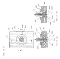
- FIG. 1 is a horizontal cross-sectional view of a fixed side mold-half and a movable side mold-half having liners thereof attached thereto, respectively, and a horizontal cross-sectional view of a molded article
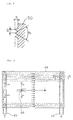
- FIG. 2 is an enlarged view of a part "C" of the molded article of FIG. 1
- FIG. 3 is a front view of the liner only of the fixed side mold-half, viewed from a cavity side
- FIG. 4 is a cross-sectional view provided by rightwardly (clockwise) rotating a cross section A-A of FIG. 3
- FIG. 5 is a cross-sectional view provided by rightwardly (clockwise) rotating a cross section B-B of FIG. 3
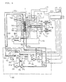
- FIG. 6 is a schematic view of an injection molding machine having the mold of FIG. 1 attached thereto, and a mold temperature adjusting apparatus.
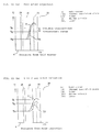
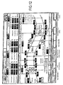
- FIG. 7 shows an example of a display view of specified temperature values of liners 48, 58 in respective molding processes
- FIG. 8 is a block diagram of a control system for controlling the injection molding machine and the mold temperature adjusting apparatus of FIG. 6
- FIG. 9 is a view corresponding to a cross section D-D of FIG. 3 , showing an incoming flow of heat medium at an end of a heat medium passage
- FIG. 10 is a view corresponding to the cross section D-D of FIG. 3 , showing an outgoing flow of heat medium at the end of the heat medium passage
- FIG. 11 is a cross-sectional view of the liners for explanation of temperature transitions thereof, immediately after injection of a molten resin and several seconds after injection of the molten resin, respectively
- FIG. 12 is an example of display view simultaneously displaying curves of actually measured temperatures of the fixed side liner and movable side liner.
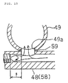
- FIG. 13 through FIG. 18 are explanatory views of improved gate bush pins according to the present invention.
- FIG. 1 is a horizontal cross-sectional view of the fixed side mold-half and the movable side mold-half separated from each other in a mold open position, and viewed from the above in a state that a molded article 50 is placed therebetween.
- Reference numeral 48 designates the liner (also called “core plate”) attached to a mold master 4 acting as the fixed side mold-half
- reference numeral 58 designates the liner attached to a mold master 5 acting as the movable side mold-half.
- the fixed side liner 48 is fixed to the mold master 4 in a manner to hold four edges of the liner by four hold members 42, respectively, thereby enabling to accommodate distortions of the liner 48 by relieving the distortions at held portions of the liner even when the liner is extended and contracted due to repeated heating and cooling thereof.
- the movable side liner 58 is fixed to the mold master 5 in a manner to hold four edges of the liner by four hold members 43, respectively, thereby enabling to accommodate distortions of the liner 58 by relieving the distortions at held portions of the liner, correspondingly to extension and contraction of the liner due to repeated heating and cooling thereof.
- Both the liner 48 and liner 58 are made of a metal material (such as stainless steel) having a thermal conductivity of 20 to 40 W/(m ⁇ K), and are in rectangular plate shapes having a thickness of 15 to 30 mm and having multiple heat medium passages (also called "temperature adjustment pipings") 48a, 58a penetratingly and parallelly formed within the plates in positions at constant distances from the cavity surfaces of the plates, respectively.
- a metal material such as stainless steel
- thermal insulation plates 38, 39 Interposed between the mold master 4 and liner 48 and between the mold master 5 and liner 58 are thermal insulation plates 38, 39 (each made of a material such as glass fiber reinforced heat-resistant resin, or ceramics), respectively, each having a thermal conductivity of 5 W/(m ⁇ K) or less.
- the liners 48, 58 are each made of a typical stainless steel, and the thermal insulation plates 38, 39 are each made of a typical heat-resistant composite material, which are both easily available and inexpensive.
- the liner 48 and liner 58 are attached to the mold master 4 and mold master 5, respectively, followed by clamping of the mold and filling of a molten resin thereinto, thereby molding the rectangle article 50 in a thin sheet shape (having a thickness of 3 mm or less) having a diagonal dimension of 17 inches or longer, i.e., a light conduction plate or diffusion plate to be used in a liquid crystal display or the like.
- the pattern of fine concavities and convexities like prisms directly formed on the liner surface in the above manner it is also possible to form a pattern of concavities and convexities on a metal thin plate and to contact and place the metal thin plate with and on the surface of the liner 48 or liner 58 such that the pattern is brought to the cavity side.
- the required molding precision is that the pattern of concavities and convexities of the liner 48 or liner 58 is transferred to one side of the molded article 50, such that the prisms on the surface of the molded article have an average height which is 90% or more of an average height of the prisms on the mold cavity surface.
- the liner 48 and liner 58 each has a pair of manifolds 49, 49 attached thereto at both side edges and reverse to the cavity such that the manifolds 49, 49 are placed to be communicated with the heat medium passages 48a, 58a of the liners 48, 58, respectively, and, as shown in FIG. 4 , the heat medium passages 48a, 58a are penetratingly formed such that the distance "c" from the cavity surface to the center of the heat medium passages 48a, 58a meets a relationship of c/t ⁇ 0.58 for the thickness "t" of the associated liner, and a relationship of p/c ⁇ 1.1 for the spacing pitch "p" of the heat medium passages 48a, 58a.
- the incoming side manifolds 49 for supplying heat media (hot water, cool water) to the heat medium passages 48a, 58a, and the outgoing side manifolds 49 are fixedly provided, respectively.
- the incoming side manifold 49 has an inlet and the outgoing side manifold 49 has an outlet which are located at the same side (the supplying direction of the heat medium is opposite to the discharging direction of the heat medium, as shown by arrows in FIG.
- the fixed side liner 48 has a plurality of gate bush pins 68 buried therein for allowing passage of a molten resin fed through a hot runner 14 attached to the mold master 4 acting as the fixed side mold-half, there is a possibility that the gate bush pins 68 buried in the liner 48 and the heat medium passages 48a penetratingly formed through the liner 48 interfere with one another because the heat medium passages 48a are so numerous and have narrow spacings therebetween.
- the gate bush pins 68 each have both sides formed with recesses 68a, respectively, thereby avoiding the noted constriction without widening the spacing pitch of the heat medium passages 48a.
- the mold clamping apparatus is configured to include a base 18 having a fixed die plate 2 fixed thereto; the fixed die plate 2 has attached thereto the mold master 4 acting as the fixed side mold-half provided with the liner 48; and the mold master 5 acting as the movable side mold-half provided with the liner 58 opposed to the mold master 4 is attached to a movable die plate 3 which is guided by guide rails 19 laid on the base 18 and which is moved through a linear bearing in a manner opposed to the fixed die plate 2.
- a hydraulic cylinder 22 Used for the movement of the movable die plate 3 (movement for opening and closing the mold) is a hydraulic cylinder 22 to be hydraulically actuated. It should be noted that it is possible to adopt an electromotive ball screw or the like, instead of hydraulic actuation.
- a plurality of tie-bars 15 each having one end formed with a screw groove, and the tie-bars 15 penetrate through through-holes of the movable die plate 3, respectively, such that a plurality of half nuts 17 placed at a side of the movable die plate 3 reverse to the mold are engaged with screw grooves 15a of the tie-bars 15 to thereby fix and constrain the movable die plate to the tie-bars in the pulling direction thereof.
- an oil pressure changeover valve 21 configured to follow commands from an injection molding machine controlling apparatus 20.
- the heat medium passages 48a of the liner 48 of the mold master 4 acting as the fixed side mold-half and the heat medium passages 58a of the liner 58 of the mold master 5 acting as the movable side mold-half, are communicated to heat medium outlets and inlets of the mold temperature adjusting apparatus 30, respectively.
- changeover valves of heat media are disposed at positions as close as possible to the liners 48, 58, respectively.
- a temperature sensor 65 contacted therewith is provided on the cavity surface of the liner 48.
- Temperature signals detected by the temperature sensors 65, 66 are sent to a mold temperature control unit 45 of the injection molding machine controlling apparatus 20, so that the temperatures of the liners 48, 58 are controlled to be the same or controlled individually, depending on the molding conditions.
- the injection unit 10 is of an electromotive type.
- a frame 6a integrally with an injection cylinder 6 having an injection nozzle which is abutted to a resin inlet of the mold master 4 acting as the fixed side mold-half during an operation of injection, and the frame 6a has a pair of servomotors 12, 12 attached thereto symmetrically at both sides of a center line of the injection cylinder 6, and the servomotors 12, 12 have output shafts having ball screw shafts 8, 8 directly connected thereto, respectively.
- the injection unit further includes an injection screw 7 provided in a manner to freely rotate and to be constrained in an axial direction by a movement frame 27, and the injection screw 7 is directly connected to an output shaft of an injection screw rotation driving motor 13 fixedly provided at the center of the movement frame 27, so that the injection screw achieves rotational feed and plasticization of a resin within the injection cylinder 6.
- the movement frame 27 has a pair of ball screw nuts 9, 9 symmetrically attached thereto, and the ball screw shafts 8, 8 are meshed with the ball screw nut 9, 9, respectively.
- the pair of servomotors 12, 12 is synchronizedly and rotatedly driven so that the injection screw 7 is caused to axially advance and retract within the injection cylinder 6 to conduct an injection operation of a resin.
- the injection unit 10 is configured to inject a molten resin into a cavity defined by the liner 48 and liner 58 upon clamping the mold master 4 acting as the fixed side mold-half and the mold master 5 acting as the movable side mold-half to each other. After cooling and solidification of a molded article, the mold master 5 acting as the movable side mold-half is released from the clamped coupling to the mold master 4 acting as the fixed side mold-half, and is separated from the mold master 4 acting as the fixed side mold-half by virtue of the operation of the hydraulic cylinder 22 for movement, thereby allowing the molded article to be taken out.
- the injection molding machine controlling apparatus 20 is configured to provide instructions according to a program for a molding process, in a manner: to actuate the oil pressure changeover valve 21 to feed a hydraulic oil to respective hydraulic cylinders responsible to processes of the injection molding machine 1; to supply electric current to the servomotors 12, 12 for injection driving of the injection unit 10 to advance and retract the injection screw 7; and to supply electric current to the injection screw rotation driving motor 13 of the injection screw 7 to plasticize a resin.
- the mold temperature adjusting apparatus 30 includes a low-temperature water tank 23 which is a heat exchanger internally including a heat medium piping through which a cooling medium is passed to adjust low-temperature water at a specified low-temperature.
- the low-temperature water tank 23 has a low-temperature water temperature sensor 63 attached thereto for detecting a water temperature within the tank 23, and the signal of a detected value is received by a mold temperature control unit 45 which in turn controls a cooling medium amount to keep the water temperature at the specified temperature.
- the apparatus further includes: a low-temperature water pump 26 placed between a feed side piping 31a and a low-temperature water piping 31b coupled to the low-temperature water tank 23; a low-temperature water pump 29 placed between the low-temperature water piping 31b and a piping 31c; and an opening/closing valve 52 between the piping 31c and a supply piping 31e; and the supply piping 31e is coupled to the manifold 49 for the heat medium passages 48a of the liner 48.
- the mold temperature adjusting apparatus further includes an opening/closing valve 56 placed between the piping 31c and a supply piping 32, the latter being connected to the manifold 49 for the heat medium passages 58a.
- the apparatus additionally includes: a return side piping 35a from the liner 48 and a return side piping 33 from the liner 58, which pipings are directly converged and connected to a piping 35c; an opening/closing valve 55 between the piping 35c and a piping coupled to the low-temperature water tank 23; and an opening/closing valve 54 between the piping 35c and a piping 35b coupled to an intermediate-temperature water tank 24.
- the intermediate-temperature water tank 24 is a heat exchanger internally including a heat medium piping through which a heat medium is passed to adjust intermediate-temperature water at a specified intermediate-temperature, and has an intermediate-temperature water temperature sensor 64 attached to the tank itself for detection of the temperature of the intermediate-temperature water.
- the intermediate-temperature water temperature sensor 64 detects a water temperature within the intermediate-temperature water tank 24, and the signal of a detected value is received by the mold temperature control unit 45 which in turn controls an amount of heat medium passing through a heat medium piping of the intermediate-temperature water tank 24 to keep the temperature of the intermediate-temperature water at a specified temperature.
- the intermediate-temperature water tank 24 has an intermediate-temperature water supply piping 41 connected thereto having an intermediate-temperature water pump 28 attached thereto for circulation of intermediate-temperature water, and the piping 41 is connected to the supply piping 31e via opening/closing valve 57, and thus connected to the manifold 49 for the heat medium passages 48a of the liner 48.
- the intermediate-temperature water supply piping 41 is connected via opening/closing valve 53 to the supply piping 32 coupled to the manifold 49 for the heat medium passages 58a of the liner 58, while the return side piping 33 from the heat medium passages 58a of the liner 58 is once connected to the return piping 35a from the heat medium passages 48a of the liner 48 and then branched into the pipings 35b, 35c again, in a manner that the discharged return water in the piping 35b is returned into the intermediate-temperature water tank 24 via opening/closing valve 54 and the discharged return water in the piping 35c is returned into the low-temperature water tank 23 via opening/closing valve 55.
- opening/closing valves 52, 56 are closed and the opening/closing valves 57, 53 are opened so that the intermediate-temperature water is supplied into the liners 48, 58, discharged water from the liners 48, 58 is caused to pass through the return side pipings 35a, 33, and thereafter, returned into the intermediate-temperature water tank 24 via piping 35b when the opening/closing valve 54 is opened, and returned into the low-temperature water tank 23 via piping 35c when the opening/closing valve 55 is opened.
- this water pressure is transmitted to the intermediate-temperature water tank 24 through a couple piping 36 via recovery tank 25, thereby enabling to increase a saturated vapor pressure of the intermediate-temperature water to regulate and hold the temperature of the intermediate-temperature water at 100°C or higher.
- the heat recovery tank 25 connected to the intermediate-temperature water tank 24 via piping 44 is a balance tank between intermediate-temperature water and low-temperature water and having a vertically cylindrical shape, which balance tank has a volume larger than a total of volumes of the heat medium passages 48a, 58a of the liners 48, 58, a volume within the supply piping 41 of intermediate-temperature water, volumes of the supply pipings 31e, 32, return side pipings 33, 35a after the coupling portion with the supply piping 41, and a volume within the piping 35b branched to the intermediate-temperature water side, which balance tank has at its upper portion an inlet from the piping 44 connected to the intermediate-temperature water tank 24, and at its lower portion a low-temperature water inlet connected to the couple piping 36 leading to the low-temperature water tank 23, and which balance tank is provided with means for restricting mixture of intermediate-temperature water with low-temperature water accommodated within the balance tank itself.
- the intermediate-temperature water is collected back into the intermediate-temperature water tank 24 while closing the opening/closing valve 55 and opening the opening/closing valve 54 and while monitoring a replacing state of the heat medium by the temperature sensors 65, 66 provided on the cavity surfaces of the liners 48, 58, and when the temperature sensors 65, 66 have detected that the intermediate-temperature water within the heat medium passages 48a, 58a is replaced by low-temperature water, the opening/closing valve 55 is opened and the opening/closing valve 54 is closed to stop collection of the intermediate-temperature water and the low-temperature water is refluxed.
- the overflowed amount of the intermediate-temperature water collected into the intermediate-temperature water tank 24 is fed to the recovery tank 25, and low-temperature water in that amount fed to the recovery tank 25 is returned from the recovery tank 25 into the low-temperature water tank 23 through the water pressure regulation valve 61.
- FIG. 8 is a block diagram of a control system, in which the blocks of components contacted with each other and the blocks connected by double lines indicate that the blocks are mechanically and internally included or abutted to each other; thick lines indicate connection by means of heat medium pipings; and thin lines indicate electric signal lines and power electric current wires.
- numelations labeled in the blocks of the components in FIG. 8 are expressed in a functional manner, so that some of them are not fully the same as those described above.
- the mold temperature control unit 45 internally includes a control processing unit (CPU), storage means for storing therein specified values, actually measured values, display images, and the like, input and output circuits, and the like. Further, there is provided image display means (image panel) 46 of the injection molding machine controlling apparatus 20 at a location visible from an operator, so as to display specified values, actually measured values, and the like of temperatures of the liners 48, 58 in the molding processes required for controlling the mold temperature control unit 45, by a display view switching operation, not limited to the molding machine control. Provided near the image display means 46 is heat medium temperature setting means 47.
- FIG. 7 shows an example of display view of specified values of temperatures of the liners 48, 58 in respective molding processes
- FIG. 12 shows an example of display view simultaneously displaying temperature curves by actually measuring temperatures of the fixed side liner 48 and movable side liner 58.
- Detected values of the temperature sensors 65, 66 for detecting temperatures of the liners 48, 58, respectively, are compared with specified values for temperatures of mold liners in respective processes in the mold temperature control unit 45, in a manner that when the liner temperatures are coincident with the specified values, the mold temperature control unit instructs the injection molding machine controlling apparatus 20 to shift into the next molding process, and instructs the mold temperature adjusting apparatus 30 to change the heat medium to be fed to the liners 48, 58 or to set a timer for determining the timing of change between heating process and cooling process.
- the injection unit 10 of the molding machine is operated for injection in a state that the opening/closing valves 53, 57, 54 are closed, supply of the intermediate-temperature heat medium is stopped, the heat medium inlets are closed, and intermediate-temperature water is kept encapsulated within the heat medium passages 48a, 58a, so that the molten resin is filled into the cavity defined by the liners 48, 58.
- the encapsulated intermediate-temperature water is maintained, to cause the temperatures of the liners 48, 58 to be naturally and gradually lowered; after a lapse of a specified time (specified by a low-temperature medium changeover timer S1) from the start of dwelling, the opening/closing valve 54 is opened and the opening/closing valves 52, 56 are opened to discharge and collect the intermediate-temperature water accumulated in the heat medium passages 48a, 58a of the liners 48, 58 and the intermediate-temperature water within the pipings into the intermediate-temperature water tank 24 while supplying low-temperature water into the liners 48, 58; and when the intermediate-temperature water within the liners 48, 58 and pipings is collected, the opening/closing valve 55 is opened and the opening/closing valve
- a dwelling process limit timer S H After a lapse of a specified time (specified by a dwelling process limit timer S H ) from the start of dwelling, or when the temperature sensors 65, 66 of the liners 48, 58 have detected that the liner temperatures have been brought to be Tg or lower, the dwelling of resin is finished.
- the opening/closing valves 52, 56 are closed to stop supply of low-temperature water into the liners 48, 58, and simultaneously therewith, the opening/closing valve 55 is closed to encapsulate the low-temperature water within the liners 48, 58, to start annealing.
- a liner temperature i.e., a thermal deformation temperature T L or lower which is a starting point of mold opening
- mold opening is conducted to take out a molded article from the mold, followed by starting encapsulation of low-temperature water; and after a lapse of a specified time (specified by an intermediate-temperature medium changeover timer S2), the opening/closing valves 53, 57 are opened to change over to supply intermediate-temperature water to thereby discharge the low-temperature heat media from the liners 48, 58 and supply and discharge pipings; and at the timing where the low-temperature water is substantially collected, the opening/closing valve 54 is opened and the opening/closing valve 55 is closed to continue supplying intermediate-temperature water, thereby raising the temperatures of the liners 48, 58 toward a liner temperature T H for starting the next filling and molding cycle.
- a liner temperature i.e., a thermal deformation temperature T L or lower which is a starting point of mold opening
- the liners 48, 58 are configured to be attached to the mold masters 4, 5 acting as the mold-halves with the thermal insulation plates 38, 39 interposed therebetween, respectively, and the liners 48, 58 have multiple heat medium passages 48a, 58a formed therethrough in a manner slightly separated from the cavity surfaces of the liners 48, 58 such that the liners are made of metal (stainless steel having a thermal conductivity of 20 to 40 W/(m ⁇ K)) which appears to have a lower thermal conductivity, resulting in that heat from the hot molten resin is conducted and spread over the whole liners 48, 58 without irregularity in a manner without absorption of the heat directly by heat media flowing through the heat medium passages 48a, 58a and without conduction of the heat from the liners 48, 58 to the mold masters 4, 5, to thereby raise the temperatures of the liners 48, 58 to proper values slightly higher than the glass transition point, thereby enabling to easily transfer patterns engraved on the liners 48, 58, respectively, onto a molded article
- the components constituting the gate of the hot runner 14 include the gate bush pins 68 as described above.
- the gate bush pins 68 are attached to the fixed side liner 48, to position the nozzles of the hot runner 14, and to constitute gates acting as introduction passages of resin, combinedly with the nozzles of the hot runner 14, respectively.
- the improved gate bush pins of the embodiments to be described hereinafter exhibit such common effects that: the yield ratio of resin is advantageously improved, and the post working process can be advantageously omitted; and additionally, roundabout passages for heat medium passages 48a are provided to mitigate the effect on the heat medium passages 48a of the liner, i.e., to avoid increase of conduit resistances of the heat medium passages 48a due to the gate bush pins, in a manner to decrease deviations of flow rates in heat medium passages 48a, thereby effectively keeping the temperature uniformity of the liner 48.
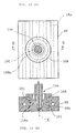
- FIG. 13 shows a first embodiment of an improved gate bush pin, in which FIG. 13(a) is a top view of the gate bush pin in case of adoption of a hot runner having a direct gate with valve gate, and FIG. 13 (b) is a view in an E-E arrow direction of FIG. 13(a) .
- This embodiment includes a gate bush pin 168 for molten resin, and the gate bush pin 168 has a side surface formed with a groove 168a concentrically with a central axis X of the gate bush pin correspondingly to a position or level where the heat medium passages 48a of the liner 48 interfere with the gate bush pin, thereby defining a heat medium roundabout passage 101 extending round about the gate bush pin 168.
- the groove 168a is formed on the side surface of the gate bush pin 168 near the position corresponding to the heat medium passages 48a of the liner 48 in a thickness direction, such that the groove 168a has a cross-sectional area which is one or more times that of each heat medium passage 48a.
- the heat medium passages 48a for temperature adjustment are provided in the liner 48 in the substantially parallel manner with the narrow pitch, and the gate bush pin 168 is placed in a configuration to penetrate the liner 48.
- the gate bush pin 168 has the side surface formed with the groove 168a concentrically with the central axis X of the gate bush pin 168 and near a position where the heat medium passages 48a of the liner 48 interfere with the gate bush pin 168, so that the groove 168a defines the heat medium roundabout passage 101 when the gate bush pin 168 is placed in the liner 48.
- heat media flowed from heat medium passages 48a upstream of the gate bush pin 168 flow into the heat medium roundabout passage 101 at the position interfering with the gate bush pin 168, thereby flowing round about the gate bush pin 168.
- the heat medium roundabout passage 101 has a downstream portion connected to heat medium passages 48a positioned downstream of the gate bush pin 168, so that the heat media are flowed out of the roundabout passage and distributed into the heat medium passages. This allows to mitigate deviations of flow rates of heat media due to the gate bush pin 168, thereby enabling to keep the uniformity of temperature distribution of the liner.
- the groove 168a is configured to have a larger area interfacing with or occupying on the gate bush pin 168, thereby enabling to enhance the temperature adjustment effect for the gate bush pin 168 and to assemble the gate bush pin 168 with a free rotational orientation, thereby effectively allowing to provide the gate bush pin without considering the positional relationship thereof to the heat medium passages.
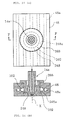
- FIG. 14 shows a second embodiment of an improved gate bush pin, in which FIG. 14(a) is a top view of the gate bush pin, and FIG. 14(b) is a view in an F-F arrow direction of FIG. 14(a) .
- This embodiment includes a gate bush pin 268 for molten resin, and the liner 48 has a liner hole 248 which penetrates through the liner and into which the gate bush pin 268 fits, in a manner that the liner hole 248 has an inside surface formed with a groove 248a concentrically with a central axis X of the gate bush pin 268 correspondingly to a position or level where the heat medium passages 48a of the liner 48 interfere with the gate bush pin 268, thereby defining a heat medium roundabout passage 102 extending round about the gate bush pin 268.
- the groove 248a is formed on the inside surface of the liner hole 248 penetrating through the liner 48 near the position corresponding to the heat medium passages 48a of the liner 48 in a thickness direction, such that the groove 248a has a cross-sectional area which is one or more times that of each heat medium passage 48a.
- the heat medium passages 48a for temperature adjustment are provided in the liner 48 in the substantially parallel manner with the narrow pitch, and the gate bush pin 268 is placed in a configuration to penetrate the liner 48.
- the liner hole 248 of the liner 48, in which the gate bush pin 268 fits, has the inside surface formed with the groove 248a concentrically with the central axis X of the gate bush pin 268 and near a position where the heat medium passages 48a of the liner 48 interfere with the gate bush pin 268, so that the groove 248a defines the heat medium roundabout passage 102 when the gate bush pin 268 is placed in the liner 48.
- heat media flowed from heat medium passages 48a upstream of the gate bush pin flow into the heat medium roundabout passage 102 at the position interfering with the gate bush pin 268, thereby flowing round about the gate bush pin 268.
- the heat medium roundabout passage 102 has a downstream portion connected to heat medium passages 48a positioned downstream of the gate bush pin 268, so that the heat media are flowed out of the roundabout passage and distributed into the heat medium passages. This allows to mitigate deviations of flow rates of heat media due to the gate bush pin 268, thereby enabling to keep the uniformity of temperature distribution of the liner 48.
- the gate bush pin 268 can be decreased in diameter, while enabling to assemble the gate bush pin 268 with a free rotational orientation, thereby effectively allowing to provide the gate bush pin 268 without considering the positional relationship thereof to the heat medium passages 48a.
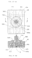
- FIG. 15 shows a third embodiment of an improved gate bush pin, in which FIG. 15(a) is a top view of the gate bush pin, and FIG. 15(b) is a view in a G-G arrow direction of FIG. 15(a) .
- This embodiment includes a gate bush pin 368 for molten resin, and the liner 48 has a liner hole 348 which penetrates through the liner and into which the gate bush pin 368 fits, in a manner that the gate bush pin 368 has a side surface formed with a groove 368a concentrically with a central axis X of the gate bush pin 368 and the liner hole 348 has an inside surface formed with a groove 348a also concentrically with the central axis X, both correspondingly to a position or level where the heat medium passages 48a of the liner 48 interfere with the gate bush pin 368, such that the groove 368a of the gate bush pin 368 and the groove 348a of the liner hole 348 cooperatively define a heat medium roundabout passage 103 extending round about the gate bush pin 368 when the gate bush pin 368 is fitted into the liner hole 348.
- the grooves 368a, 348a are formed on the side surface of the gate bush pin 368 and on the inside surface of the liner hole 348 penetrating through the liner 48, respectively, near the position corresponding to the heat medium passages 48a of the liner 48 in a thickness direction, such that the grooves cooperatively have a cross-sectional area which is one or more times that of each heat medium passage 48a.
- the heat medium passages 48a for temperature adjustment are provided in the liner 48 in the substantially parallel manner with the narrow pitch, and the gate bush pin 368 is placed in a configuration to penetrate the liner 48.
- the gate bush pin 368 has the side surface formed with the groove 368a concentrically with the central axis X of the gate bush pin 368 and the liner hole 348 has the inside surface formed with the groove 348a, both correspondingly to the position or level where the heat medium passages 48a of the liner 48 interfere with the gate bush pin 368 and near a position where the heat medium passages 48a of the liner 48 interfere with the gate bush pin 368, so that the groove 368a of the gate bush pin 368 and the groove 348a of the liner hole 348 cooperatively define the heat medium roundabout passage 103 extending round about the gate bush pin 368 when the gate bush pin 368 is placed in the liner 48.
- heat media flowed from heat medium passages 48a upstream of the gate bush pin flow into the heat medium roundabout passage 103 at the position interfering with the gate bush pin 368, thereby flowing round about the gate bush pin 368.
- the heat medium roundabout passage 103 has a downstream portion connected to heat medium passages 48a positioned downstream of the gate bush pin 368, so that the heat media are flowed out of the roundabout passage and distributed into the heat medium passages. This allows to mitigate deviations of flow rates of heat media due to the gate bush pin 368, thereby enabling to keep the uniformity of temperature distribution of the liner 48.
- the heat medium roundabout passage 103 is allowed to have an increased cross-sectional area to decrease a round about resistance, thereby enabling to improve the temperature uniformity of the liner 48 and to assemble the gate bush pin with a free rotational orientation, thereby effectively allowing to provide the gate bush pin 368 without considering the positional relationship thereof to the heat medium passages 48a.
- FIG. 16 shows a fourth embodiment of an improved gate bush pin, in which FIG. 16(a) is a top view of the gate bush pin, and FIG. 16(b) is a view in an H-H arrow direction of FIG. 16(a) .
- This embodiment includes a gate bush pin 468 for molten resin, and the liner 48 has a liner hole 448 which penetrates through the liner and into which the gate bush pin 468 fits, in a manner that the gate bush pin 468 has a side surface with large outer diameter and small outer diameter portions to form a stepped portion 468a therebetween and the liner hole 448 also has an inside surface with large inner diameter and small inner diameter portions to form a stepped portion 448a therebetween, both correspondingly to a position or level where the heat medium passages 48a of the liner 48 interfere with the gate bush pin, such that the stepped portions 468a, 448a of the gate bush pin 468 and liner hole 448 cooperatively define a space extending around the pin by virtue of the positional difference therebetween, and the space defines a heat medium roundabout passage 104 extending round about the gate bush pin 468 when the gate bush pin 468 is fitted into the liner hole 448.
- the space around the gate bush pin 468 cooperatively defined by the stepped portion 468a of the gate bush pin 468 and the stepped portion 448a of the liner hole 448 establishes the heat medium roundabout passage 104 near the position corresponding to the heat medium passages 48a of the liner 48 in a thickness "t" direction, such that the space has a cross-sectional area which is one or more times that of each heat medium passage 48a.
- the heat medium passages 48a for temperature adjustment are provided in the liner 48 in the substantially parallel manner with the narrow pitch, and the gate bush pin 468 is placed in a configuration to penetrate the liner 48.
- the gate bush pin 468 has the side surface with large outer diameter and small outer diameter portions to form the stepped portion 468a therebetween correspondingly to the position or level where the heat medium passages 48a of the liner 48 interfere with the gate bush pin 468.
- the liner hole 448 also has the inside surface with large inner diameter and small inner diameter portions to form the stepped portion 448a therebetween, correspondingly to the position or level where the heat medium passages 48a of the liner 48 interfere with the gate bush pin, thereby defining the heat medium roundabout passage 104 when the gate bush pin 468 is placed in the liner 48.
- heat media flowed from heat medium passages 48a upstream of the gate bush pin 468 flow into the heat medium roundabout passage 104 at the position interfering with the gate bush pin 468, thereby flowing round about the gate bush pin 468.
- the heat medium roundabout passage 104 has a downstream portion connected to heat medium passages 48a positioned downstream of the gate bush pin 468, so that the heat media are flowed out of the roundabout passage and distributed into the heat medium passages. This allows to mitigate deviations of flow rates of heat media due to the gate bush pin 468, thereby enabling to keep the uniformity of temperature distribution of the liner 48.
- the heat medium roundabout passage 104 is allowed to have an increased cross-sectional area to decrease a round about resistance, thereby enabling to improve the temperature uniformity of the liner 48. Moreover, fabrication of the heat medium roundabout passage 104 is facilitated while allowing to assemble the gate bush pin with a free rotational orientation, thereby effectively allowing to provide the gate bush pin without considering the positional relationship thereof to the heat medium passages. This embodiment also has an advantage of facilitated fabrication.
- FIG. 17 shows a fifth embodiment of an improved gate bush pin, in which FIG. 17(a) is a top view of the gate bush pin, and FIG. 17(b) is a view in an I-I arrow direction of FIG. 17(a) .
- This embodiment includes a gate bush pin 568 for molten resin, and the heat medium passages 48a penetrating through the liner 48 are provided with transverse heat medium passages 505 near upstream and downstream sides of the gate bush pin 568, respectively, correspondingly to a position or level where the heat medium passages 48a of the liner 48 interfere with the gate bush pin 568, such that the passages 505 transversely communicates the heat medium passages 48a with one another, respectively.
- the heat medium passages 48a for temperature adjustment are provided in the liner 48 in the substantially parallel manner with the narrow pitch, and the gate bush pin 568 is placed in a configuration to penetrate the liner 48.
- the gate bush pin 568 has the side surface formed with the groove 568a concentrically with a central axis X of the gate bush pin 568 and near a position where the heat medium passages 48a of the liner 48 interfere with the gate bush pin 568, so that the groove 568a defines the heat medium roundabout passage 105 between the groove itself and the inner peripheral surface of the liner hole 548 when the gate bush pin 568 is placed in the liner 48.
- transverse heat medium passages 505 are provided near the upstream side and downstream side of the gate bush pin 568 in a manner to extend substantially perpendicularly to the heat medium passages 48a and penetrate the liner 48 to thereby transversely communicate the heat medium passages 48a with one another.
- the heat media flowed from the heat medium passages 48a upstream of the gate bush pin 568 flow into the upstream side transverse heat medium passage 505 upstream of a position where the heat medium passages interfere with the gate bush pin 568, the media then flow round about the gate bush pin 568, and the media flow into the downstream side transverse heat medium passage 505 downstream of the gate bush pin and are distributed into the heat medium passages 48a.
- heat media flowed from heat medium passages 48a upstream of the gate bush pin 568 flow into the heat medium roundabout passage 105 at the position interfering with the gate bush pin 568, thereby flowing round about the gate bush pin 568.
- the heat medium roundabout passage 105 has a downstream portion connected to heat medium passages positioned downstream of the gate bush pin, so that the heat media are flowed out of the roundabout passage and distributed into the heat medium passages.
- transverse heat medium passages 505 upstream and downstream of the gate bush pin 568 serve to distribute and converge the heat media in a manner to assist the function of the heat medium roundabout passage 105. This allows to mitigate deviations of flow rates of heat media due to the gate bush pin 568, thereby enabling to keep the uniformity of temperature distribution of the liner 48.
- the heat medium roundabout passage is allowed to have an increased cross-sectional area to decrease a round about resistance, thereby enabling to improve the temperature uniformity of the liner 48. Moreover, fabrication of the heat medium roundabout passage is facilitated while effectively allowing to assemble the gate bush pin with a free rotational orientation, thereby effectively allowing to provide the gate bush pin without considering the positional relationship thereof to the heat medium passages.
- this embodiment has been described by adopting the gate bush pin 568 and heat medium roundabout passage 105 which are the same as the gate bush pin 168 and heat medium roundabout passage 101 of the first embodiment, the feature of this embodiment resides in that the transverse heat medium passages 505 are provided near upstream side and downstream side of the gate bush pin in a manner to traverse the heat medium passages 48a, so that it is also possible to adopt any ones of the gate bush pin, heat medium roundabout passages, and the like of the first embodiment through fourth embodiment.
- FIG. 18 shows a sixth embodiment of an improved gate bush pin, in which FIG. 18(a) is a top view of the gate bush pin, FIG. 18(b) is a cross-sectional view in a J-J arrow direction of FIG. 18(a), and FIG. 18(c) is a cross-sectional view in a K-K arrow direction of FIG. 18(a) .
- This embodiment includes a gate bush pin 668 for molten resin
- the gate bush pin 668 has a side surface formed with grooves 668a which grooves are located to oppose each other in the direction of heat medium passage 48a about a central axis X of the gate bush pin and which grooves are oriented in a direction substantially perpendicular to the heat medium passages 48a
- the gate bush pin 668 is formed with heat medium communication passages 668b penetrating the gate bush pin 668 substantially perpendicularly to the opposed grooves 668a to thereby communicate the grooves 668a with each other, respectively, thereby defining a heat medium roundabout passage 106 extending substantially round about the gate bush pin 668.
- the heat medium passages 48a for temperature adjustment are provided in the liner 48 in the substantially parallel manner with the narrow pitch, and the gate bush pin 668 is placed in a configuration to penetrate the liner 48.
- the gate bush pin 668 has upstream and downstream side surfaces formed with the grooves 668a opposed to each other in the direction of heat medium passages 48a and substantially perpendicular to heat medium passages 48a, such that the grooves 668a define manifolds at upstream and downstream sides of the gate bush pin 668, respectively, which manifolds attain convergence and distribution of heat media between the grooves and the inner peripheral surface of the liner hole 648, respectively.
- the heat medium communication passages 668b penetrating the gate bush pin 668 are provided substantially perpendicularly to the opposing grooves 668a to thereby communicate with each other, thereby defining the heat medium roundabout passage 106 with the groove 668a when the gate bush pin 668 is placed in the liner 48.
- heat media flowed from heat medium passages 48a upstream of the gate bush pin 668 flow into the heat medium roundabout passage 106 comprising: the grooves 668a opposed to each other in the direction of heat medium passages 48a and substantially perpendicular to heat medium passages 48a; and the heat medium communication passages 668b penetrating the gate bush pin 668 substantially perpendicularly to the groove 668a to thereby communicate the opposed grooves 668a with each other, respectively; at the position interfering with the gate bush pin 668, thereby flowing substantially round about the gate bush pin 668.
- the heat medium roundabout passage 106 has a downstream portion connected to heat medium passages 48a positioned downstream of the gate bush pin 668, so that the heat media are flowed out of the roundabout passage and distributed into the heat medium passages. This allows to mitigate deviations of flow rates of heat media due to the gate bush pin, thereby enabling to keep the uniformity of temperature distribution of the liner. Further, in addition to the above-mentioned common effects, it becomes possible to ensure wider spaces acting as the manifolds at the gate bush pin, thereby enabling to effectively improve the flow rate distribution.
- An article was molded by a mold for injection molding, having the liners shown in FIG. 1 and FIG. 3 .
- the molded article was a planar diffusion plate in a shape of 264 mmx350 mm (diagonal dimension of 17.26 inches) with a thickness of 2 mm.
- the mold liners each had a thickness "t" of 16mm, and the liners were each uniformly formed therein with heat medium passages having an inner diameter of 6 mm with a pitch of 10 mm.
- the heat medium passages had centers separated from the cavity surface of each liner by a distance "c" of 9.5 mm, so that c/t was about 0.59.
- Further used were thermal insulation plates (thermal conductivity: 0.21 W/(m ⁇ K)) each having a thickness of 3mm, between the liners and associated mold masters, respectively.
- the fixed side liner had a surface formed with a prism pattern having an apex angle of 90°, for light diffusion.
- an injection molding machine having a mold clamping force of 350tonf. Further used were an intermediate-temperature medium supply apparatus, a low-temperature medium supply apparatus, and an intermediate-temperature medium/low-temperature medium changeover apparatus.
- the intermediate-temperature medium supply apparatus was arbitrarily set at a specified temperature between 95°C and 110°C depending on a test condition, and the low-temperature medium supply apparatus was set at 30°C.
- Temperatures of the movable side liner and fixed side liner were measured by thermocouples incorporated in the liners, respectively.
- Adopted as a resin material was a COP (cyclo-olefin polymer: ZEONOR (Trademark) 1060R by ZEON Corporation, having a glass transition point of 100°C), to perform molding of the diffusion plate.
- COP cyclo-olefin polymer: ZEONOR (Trademark) 1060R by ZEON Corporation, having a glass transition point of 100°C
- the exemplary configuration #1 was conducted for comparison of qualities of molded articles and molding cycles, depending on liner temperatures.
- the fixed side liner and movable side liner were supplied with an intermediate-temperature medium such that the intermediate-temperature medium was caused to by-pass a temperature adjustment circuit and was encapsulated within the liners when the temperatures of the liners had reached 95°C, and injection of a resin was then started.
- the injection molding machine was set at 280°C in its cylinder temperature. Completion of injection resulted in changeover to a low-temperature medium at the time of changeover to a dwelling process, to start cooling of a molded article. Cooling was conducted for 22 seconds, and then the molded article was taken out.
- thermocouples incorporated in the liners that the liner temperatures after filling of the resin were raised to 108°C at the highest by heat input from the resin.
- the thus obtained article exhibited an excellent appearance, free of warpage and shrinkage.
- the molding cycle was 58 seconds in this case.
- the molded article was measured for its prism pattern on its surface by a Super Depth Surface Profile Measurement Microscope VK-8550 manufactured by KEYENCE Corporation, and exhibited a transference ratio of 90% or more over the whole surface of the molded article.
- the temperature of the liners upon injection was set at the glass transition point or lower, thereby enabling a decreased variation amplitude of the liner temperature upon heating and cooling as compared to a situation of the liner temperature higher than the glass transition point, thereby exhibiting effects that energies required for heating and cooling the liners of the mold can be decreased, and the molding cycle can be shortened.
- Table 1 ⁇ Comparative Examples 1, 2, Examples 1, 2> Liner Material Liner tempterature Cooling start timing Cooling time Transference ratio Slip-page Molding cycle Com.
- Ex. 1 HPM38 86°C Upon completion of injection 22 sec 70 to 99% No 58 sec Ex. 1 HPM38 95°C Upon completion of injection 22 sec 90% or more No 58 sec Ex. 2 HPM38 100°C Upon completion of injection 22 sec 90% or more No 60 sec Com.
- Ex. 2 HPM38 105°C Upon completion of injection 22 sec 90% or more Yes 62 sec
- This exemplary configuration was a test for setting a liner temperature at 95°C and adopting a liner material having a different thermal conductivity.
- NAK80 thermal conductivity: 39.3 W/ (m ⁇ K)
- S50C thermal conductivity: 50.5 W/(m ⁇ K)
- HPM38 high carbon steel for plastic-oriented mold
- the liner temperature upon injection was kept constant at 95°C, and molding tests were performed for respective materials, thereby evaluating transferabilities of obtained molded articles. Excellent molded articles were obtained in case of NAK80 having a thermal conductivity higher than that of HPM38. The highest temperature of the liner was 106°C.
- This exemplary configuration is provided for explaining effects of the present invention concerning: a distance ""c" from a liner surface to a center of a heat medium passage; a distance (pitch) "p” between neighboring heat medium passages; and a thickness "t” of a mold liner.
- Table 3 shows a result of non-stationary heat transfer analysis where the initial temperature of liner was set at 80°C, and the temperature of intermediate-temperature medium was set at 110°C.
- NAK80 15.5 mm 7.7 5 mm 10.0 mm 0.5 1.29 2.5°C Undesirable Com.
- NAK80 16.0 mm 9.5 mm 15.0 mm 0.59 1.58 4.1°C Undesirable *1: thickness of liner *2: distance from liner surface to center of heat medium passage *3: distance between neighboring heat medium passages
- Example 1 start timing of cooling of liners was set at the start timing of dwelling.
- the start point of dwelling was selected to be a point where 90% or more of resin was filled in the cavity relative to the volume thereof.
- the obtained molded article exhibited a pattern transference ratio of 90% or more.
- Comparative Example 4 is a situation where the start timing of cooling was simultaneous with start of injection. In this case, cooling is started at part of the mold before the cavity is filled with resin in its entirety, thereby bringing about variances in pattern transference ratios of 70 to 99%.
- [Table 4] ⁇ Examples 1, 5, Comparative Example 4> Liner Material Liner Temperature Cooling start timing Cooling time Transference ratio Slip-page Molding cycle Ex. 1 HPM38 95°C Upon completion of injection 22 sec 90% or more No 58 sec Ex. 5 HPM38 95°C Upon completion of dwelling 22 sec 92% or more No 63 sec or more Com. Ex. 4 HPM38 95°C Upon start of injection 22 sec 70 to 99% No 57 sec
Applications Claiming Priority (2)
| Application Number | Priority Date | Filing Date | Title |
|---|---|---|---|
| JP2005273635 | 2005-09-21 | ||
| PCT/JP2006/318600 WO2007034815A1 (ja) | 2005-09-21 | 2006-09-20 | 金型、金型温度調整方法、金型温度調整装置、射出成形方法、射出成形機、及び熱可塑性樹脂シート |
Publications (3)
| Publication Number | Publication Date |
|---|---|
| EP1950020A1 EP1950020A1 (en) | 2008-07-30 |
| EP1950020A4 EP1950020A4 (en) | 2010-12-08 |
| EP1950020B1 true EP1950020B1 (en) | 2013-08-28 |
Family
ID=37888858
Family Applications (1)
| Application Number | Title | Priority Date | Filing Date |
|---|---|---|---|
| EP06810296.1A Active EP1950020B1 (en) | 2005-09-21 | 2006-09-20 | Mold, mold temperature regulation method, mold temperature regulation device, injection molding method, injection molding machine |
Country Status (6)
| Country | Link |
|---|---|
| EP (1) | EP1950020B1 (zh) |
| JP (1) | JP4865719B2 (zh) |
| KR (1) | KR100976292B1 (zh) |
| CN (1) | CN101287580B (zh) |
| TW (1) | TW200722267A (zh) |
| WO (1) | WO2007034815A1 (zh) |
Cited By (1)
| Publication number | Priority date | Publication date | Assignee | Title |
|---|---|---|---|---|
| WO2023193106A1 (en) * | 2022-04-08 | 2023-10-12 | Husky Injection Molding Systems Ltd. | Methods for heating a hot runner of an injection molding system |
Families Citing this family (40)
| Publication number | Priority date | Publication date | Assignee | Title |
|---|---|---|---|---|
| JP4836131B2 (ja) * | 2006-09-26 | 2011-12-14 | 三菱重工プラスチックテクノロジー株式会社 | 急速加熱冷却が可能な金型 |
| JP5073430B2 (ja) | 2007-09-21 | 2012-11-14 | コマツ産機株式会社 | 熱プレス成形装置及び同装置のための金型システム |
| DE102008045006A1 (de) * | 2008-08-29 | 2010-03-04 | Kraussmaffei Technologies Gmbh | Verfahren und Vorrichtung zur variothermen Temperierung von Spritzgießwerkzeugen |
| WO2010041483A1 (ja) * | 2008-10-09 | 2010-04-15 | 三菱重工プラスチックテクノロジー株式会社 | 射出成形装置及び射出成形方法 |
| US7993551B1 (en) * | 2008-12-01 | 2011-08-09 | Honda Motor Co., Ltd. | Bypass cooling reduction on high pressure die cast machines |
| AT507718B1 (de) | 2008-12-16 | 2010-11-15 | Engel Austria Gmbh | Spritzgiessmaschine |
| KR100946323B1 (ko) * | 2009-02-23 | 2010-03-09 | 송형천 | 단열수단을 구비한 사출시스템 |
| KR100914030B1 (ko) * | 2009-02-23 | 2009-08-28 | 송형천 | 전열부재를 구비한 매니폴드 및 전열부재의 장착방법 |
| JP5087585B2 (ja) * | 2009-04-15 | 2012-12-05 | 三菱重工プラスチックテクノロジー株式会社 | 射出成形方法及び射出成形装置 |
| WO2010123329A2 (ko) * | 2009-04-24 | 2010-10-28 | Song Hyeong-Cheon | 단열수단을 구비한 사출시스템 |
| CN101531051B (zh) * | 2009-04-27 | 2011-02-16 | 宁海县大鹏模具塑料有限公司 | 隔热节能结构的电热高光注塑模具 |
| JP5610816B2 (ja) * | 2009-05-20 | 2014-10-22 | パナソニック株式会社 | インモールド成形方法およびインモールド成形金型 |
| JP2011020337A (ja) * | 2009-07-15 | 2011-02-03 | Seiki Corp | 射出成形機における密閉型冷却ブッシュ |
| JP5496649B2 (ja) * | 2009-12-28 | 2014-05-21 | 株式会社富士精工 | 射出成形方法及び射出成形装置 |
| JP5587631B2 (ja) * | 2010-02-10 | 2014-09-10 | 富士フイルム株式会社 | 射出成形用金型および射出成形方法 |
| JP5460385B2 (ja) * | 2010-03-04 | 2014-04-02 | 株式会社岐阜多田精機 | 樹脂成形用金型ユニット及び樹脂成形用金型の温度制御方法 |
| CN102085711A (zh) * | 2010-12-23 | 2011-06-08 | 上海煜鹏通讯电子有限公司 | 注塑件生产用模具 |
| BR112013017680B1 (pt) * | 2011-01-25 | 2020-10-06 | Lego A/S | Método para a fabricação de uma peça de moldagem para uma ferramenta de moldagem por injeção, peça de moldagem para uma ferramenta de moldagem por injeção e ferramenta de moldagem por injeção |
| KR101406080B1 (ko) * | 2012-09-04 | 2014-06-13 | (주)아모레퍼시픽 | 이중구조를 갖는 사출금형 및 이의 제조방법 |
| GB201307436D0 (en) * | 2013-04-25 | 2013-06-05 | Surface Generation Ltd | Mould tool heat transition management |
| KR101536077B1 (ko) * | 2014-07-11 | 2015-07-10 | 이상문 | 이어팁 제조 장치 |
| KR101559255B1 (ko) | 2014-09-19 | 2015-10-13 | 이상문 | 이중 지지대를 갖는 이어팁 제조 장치 |
| EP3444095B1 (en) * | 2016-04-15 | 2020-05-27 | Asahi Kasei Kabushiki Kaisha | Molding die |
| DE202016103853U1 (de) * | 2016-07-15 | 2017-07-18 | Friedrich Glas | Formkern-Temperiersystem zum Herstellen von nichtzylindrischen Formteilen |
| CN111263691B (zh) * | 2017-09-08 | 2022-04-01 | 日精Asb机械株式会社 | 模具 |
| JP2019072862A (ja) * | 2017-10-12 | 2019-05-16 | 均賀科技股▲ふん▼有限公司Jun He Technology Co., Ltd. | 光学シート射出成形のモジュール構造 |
| JP2019072989A (ja) * | 2017-10-16 | 2019-05-16 | トリニティ工業株式会社 | 加飾部品及びその製造方法 |
| JP7017459B2 (ja) * | 2018-04-05 | 2022-02-08 | 旭化成株式会社 | 成形用金型 |
| CN108407242B (zh) * | 2018-05-11 | 2023-10-27 | 珠海格力精密模具有限公司 | 模具 |
| FR3083464B1 (fr) | 2018-07-03 | 2022-06-24 | Lethiguel | Procede et dispositif pour le controle de la temperature locale d'une piece lors de sa fabrication par moulage |
| CN109109233B (zh) * | 2018-10-26 | 2023-09-22 | 宁波华热机械制造有限公司 | 一种模温控制水路快速切换管路及其控制方法 |
| US10538022B1 (en) * | 2018-10-31 | 2020-01-21 | Peak 3, LLC | Polymer injection-molding mold and related methods |
| CN110076320A (zh) * | 2019-05-26 | 2019-08-02 | 深圳市宝田精工塑胶模具有限公司 | 温控系统以及包括该温控系统的锌合金成型模具 |
| CN110238473A (zh) * | 2019-05-30 | 2019-09-17 | 开平市盈光机电科技有限公司 | 一种设置有特别水道装置的唧嘴的制作工艺 |
| CN110253837B (zh) * | 2019-07-23 | 2021-03-23 | 山东劳动职业技术学院(山东劳动技师学院) | 一种可调节温度的机电一体化模具 |
| CN112155418A (zh) * | 2020-09-27 | 2021-01-01 | 李新亚 | 节能省时水壶 |
| JP2022120888A (ja) * | 2021-02-08 | 2022-08-19 | 本田技研工業株式会社 | 射出成形方法及び射出成形装置 |
| KR102374691B1 (ko) * | 2022-01-06 | 2022-03-15 | (주)대원콘크리트 | 레진관 성형틀의 소켓플랜지 및 단부켓칭플랜지 제작방법 및 이를 이용하여 성형 제작된 레진관 |
| CN116079972B (zh) * | 2022-12-27 | 2024-01-30 | 广东新劲力精密机械有限公司 | 一种具有节能隔热结构的橡胶油压机 |
| CN117817972A (zh) * | 2024-03-06 | 2024-04-05 | 南安市巴舵建材有限公司 | 一种防变形的塑料产品加工用注塑成型设备 |
Family Cites Families (20)
| Publication number | Priority date | Publication date | Assignee | Title |
|---|---|---|---|---|
| IT1030763B (it) * | 1974-10-30 | 1979-04-10 | Montedison Spa | Stampo d iniezione termicamente isolato per materiali plasici preferibilmente semiespansi |
| JPS5812715A (ja) * | 1981-07-16 | 1983-01-24 | Matsushita Electric Ind Co Ltd | 樹脂成形用金型 |
| JPS5812716A (ja) * | 1981-07-16 | 1983-01-24 | Matsushita Electric Ind Co Ltd | 成形金型の断熱用ダイプレ−トおよびその製造方法 |
| JP2738974B2 (ja) * | 1990-07-31 | 1998-04-08 | 三菱重工業株式会社 | 金 型 |
| JP3305736B2 (ja) * | 1991-03-03 | 2002-07-24 | 有限会社コーキ・エンジニアリング | 成形用金型及びその製造方法 |
| JPH0524076A (ja) * | 1991-07-24 | 1993-02-02 | Fuji Photo Film Co Ltd | 射出成形用金型 |
| JPH05154880A (ja) * | 1991-12-06 | 1993-06-22 | Hitachi Ltd | プラスチックレンズの成形金型及び成形方法 |
| WO1994012390A2 (en) * | 1992-11-24 | 1994-06-09 | United Technologies Corporation | Coolable rotor blade structure |
| US5423670A (en) * | 1993-10-08 | 1995-06-13 | Hamel; Julio E. | Enhanced thermal transfer injection molding apparatus |
| JP3444698B2 (ja) * | 1995-05-26 | 2003-09-08 | 三菱エンジニアリングプラスチックス株式会社 | ポリアセタール樹脂から成る成形品、及びポリアセタール樹脂から成る成形品の射出成形方法 |
| JP3839097B2 (ja) * | 1996-05-24 | 2006-11-01 | 日本ジーイープラスチックス株式会社 | 温度制御容易な金型構造 |
| JPH1029215A (ja) * | 1996-07-15 | 1998-02-03 | Tohoku Munekata Kk | プラスチック製品成形用金型及びこの金型の製法 |
| EP0909626A3 (en) * | 1997-10-17 | 2000-02-02 | TOHOKU MUNEKATA Co., Ltd. | Method and apparatus for injection moulding plastics |
| TW538260B (en) * | 2000-04-28 | 2003-06-21 | Sumitomo Chemical Co | Method for producing light transmitting plate |
| JP3601463B2 (ja) * | 2000-05-26 | 2004-12-15 | 住友化学工業株式会社 | パターンを有する大型導光板の製造方法 |
| EP1446274A4 (en) * | 2001-10-26 | 2010-06-30 | Aclara Biosciences Inc | SYSTEM AND METHOD FOR SPLASHED MICROREPLICATION OF MICROFLUIDATE SUBSTRATES |
| JP4392744B2 (ja) * | 2003-03-25 | 2010-01-06 | Sabicイノベーティブプラスチックスジャパン合同会社 | 無塗装自動車外板用成形品の成形方法および成形品 |
| JP2004322597A (ja) * | 2003-04-28 | 2004-11-18 | Nippon Zeon Co Ltd | 射出成形用金型及び射出成形品の製造方法 |
| JP2005014278A (ja) * | 2003-06-24 | 2005-01-20 | Tdk Corp | スタンパを保持する面に断熱層とダイヤモンド様炭素膜を施した光ディスク成形金型とそれを使用する成型方法 |
| JP2005238456A (ja) * | 2004-02-24 | 2005-09-08 | Sumitomo Chemical Co Ltd | 偏肉大型導光板の製造方法 |
-
2006
- 2006-09-20 WO PCT/JP2006/318600 patent/WO2007034815A1/ja active Application Filing
- 2006-09-20 JP JP2007536512A patent/JP4865719B2/ja active Active
- 2006-09-20 EP EP06810296.1A patent/EP1950020B1/en active Active
- 2006-09-20 KR KR1020087006821A patent/KR100976292B1/ko not_active IP Right Cessation
- 2006-09-20 CN CN2006800349124A patent/CN101287580B/zh active Active
- 2006-09-21 TW TW095135011A patent/TW200722267A/zh unknown
Cited By (1)
| Publication number | Priority date | Publication date | Assignee | Title |
|---|---|---|---|---|
| WO2023193106A1 (en) * | 2022-04-08 | 2023-10-12 | Husky Injection Molding Systems Ltd. | Methods for heating a hot runner of an injection molding system |
Also Published As
| Publication number | Publication date |
|---|---|
| TW200722267A (en) | 2007-06-16 |
| JP4865719B2 (ja) | 2012-02-01 |
| CN101287580A (zh) | 2008-10-15 |
| WO2007034815A1 (ja) | 2007-03-29 |
| JPWO2007034815A1 (ja) | 2009-03-26 |
| EP1950020A4 (en) | 2010-12-08 |
| CN101287580B (zh) | 2011-08-03 |
| KR100976292B1 (ko) | 2010-08-16 |
| EP1950020A1 (en) | 2008-07-30 |
| TWI322757B (zh) | 2010-04-01 |
| KR20080047407A (ko) | 2008-05-28 |
Similar Documents
| Publication | Publication Date | Title |
|---|---|---|
| EP1950020B1 (en) | Mold, mold temperature regulation method, mold temperature regulation device, injection molding method, injection molding machine | |
| CN101091845B (zh) | 隔膜滤板及成型方法 | |
| KR101824486B1 (ko) | 금형의 3차원 급속 가열 냉각구조 및 그 방법 | |
| JP2008110498A (ja) | 射出成形機の型締装置および射出成形機の成形方法 | |
| CN110001011B (zh) | 多层多孔式外部气体辅助注塑模 | |
| EP1741539B1 (en) | Method and apparatus for injection molding with direct insert thermal control | |
| TWI406751B (zh) | Optical part manufacturing apparatus and manufacturing method thereof | |
| CN216992766U (zh) | 一种免试铸的温控模具 | |
| US20080265465A1 (en) | Apparatus for Injection Compression Molding and Method of Molding Articles | |
| KR20160064141A (ko) | 성형기 | |
| CN211194793U (zh) | 多层多孔式外部气体辅助注塑模 | |
| KR20210103086A (ko) | 금형 온도 조정 장치 및 사출 성형기 | |
| JP2914699B2 (ja) | 二層射出圧縮成形方法および圧縮成形金型 | |
| JP5038052B2 (ja) | 成形装置および成形方法 | |
| CN205818381U (zh) | 一种高精度高效率注塑模具 | |
| KR100828182B1 (ko) | 3차원 열교환 구조를 구비한 금형 및 그 제작방법 | |
| KR100462637B1 (ko) | 고무성형용 웨이스트레스 장치 | |
| CN114103014B (zh) | 一种注塑模具的工作方法 | |
| CN201098574Y (zh) | 高效率长寿命多功能隔膜和滤板 | |
| JP3914477B2 (ja) | 射出成形金型 | |
| CN212826611U (zh) | 一出四针阀式冷流道模座 | |
| JPH02113909A (ja) | 型締装置 | |
| KR100504956B1 (ko) | 고무성형용 웨이스트레스 제조방법 | |
| CN111113832A (zh) | 隔热结构装置、注塑成型机以及控制热传递和形变量一致的方法 | |
| JP2024033952A (ja) | 射出成形機 |
Legal Events
| Date | Code | Title | Description |
|---|---|---|---|
| PUAI | Public reference made under article 153(3) epc to a published international application that has entered the european phase |
Free format text: ORIGINAL CODE: 0009012 |
|
| 17P | Request for examination filed |
Effective date: 20080321 |
|
| AK | Designated contracting states |
Kind code of ref document: A1 Designated state(s): AT |
|
| DAX | Request for extension of the european patent (deleted) | ||
| RBV | Designated contracting states (corrected) |
Designated state(s): AT |
|
| A4 | Supplementary search report drawn up and despatched |
Effective date: 20101109 |
|
| GRAP | Despatch of communication of intention to grant a patent |
Free format text: ORIGINAL CODE: EPIDOSNIGR1 |
|
| GRAS | Grant fee paid |
Free format text: ORIGINAL CODE: EPIDOSNIGR3 |
|
| GRAA | (expected) grant |
Free format text: ORIGINAL CODE: 0009210 |
|
| AK | Designated contracting states |
Kind code of ref document: B1 Designated state(s): AT |
|
| REG | Reference to a national code |
Ref country code: AT Ref legal event code: REF Ref document number: 629033 Country of ref document: AT Kind code of ref document: T Effective date: 20130915 |
|
| PLBE | No opposition filed within time limit |
Free format text: ORIGINAL CODE: 0009261 |
|
| STAA | Information on the status of an ep patent application or granted ep patent |
Free format text: STATUS: NO OPPOSITION FILED WITHIN TIME LIMIT |
|
| 26N | No opposition filed |
Effective date: 20140530 |
|
| PGFP | Annual fee paid to national office [announced via postgrant information from national office to epo] |
Ref country code: AT Payment date: 20230825 Year of fee payment: 18 |