EP1903839B1 - Verfahren zur Herstellung einer Leiterplatte mit einer wärmeabstrahlenden Struktur - Google Patents
Verfahren zur Herstellung einer Leiterplatte mit einer wärmeabstrahlenden Struktur Download PDFInfo
- Publication number
- EP1903839B1 EP1903839B1 EP07018384.3A EP07018384A EP1903839B1 EP 1903839 B1 EP1903839 B1 EP 1903839B1 EP 07018384 A EP07018384 A EP 07018384A EP 1903839 B1 EP1903839 B1 EP 1903839B1
- Authority
- EP
- European Patent Office
- Prior art keywords
- solder
- land portion
- absorption
- metal mask
- viaholes
- Prior art date
- Legal status (The legal status is an assumption and is not a legal conclusion. Google has not performed a legal analysis and makes no representation as to the accuracy of the status listed.)
- Expired - Fee Related
Links
Images


Classifications
-
- H—ELECTRICITY
- H05—ELECTRIC TECHNIQUES NOT OTHERWISE PROVIDED FOR
- H05K—PRINTED CIRCUITS; CASINGS OR CONSTRUCTIONAL DETAILS OF ELECTRIC APPARATUS; MANUFACTURE OF ASSEMBLAGES OF ELECTRICAL COMPONENTS
- H05K1/00—Printed circuits
- H05K1/02—Details
- H05K1/0201—Thermal arrangements, e.g. for cooling, heating or preventing overheating
- H05K1/0203—Cooling of mounted components
- H05K1/0204—Cooling of mounted components using means for thermal conduction connection in the thickness direction of the substrate
- H05K1/0206—Cooling of mounted components using means for thermal conduction connection in the thickness direction of the substrate by printed thermal vias
-
- H—ELECTRICITY
- H05—ELECTRIC TECHNIQUES NOT OTHERWISE PROVIDED FOR
- H05K—PRINTED CIRCUITS; CASINGS OR CONSTRUCTIONAL DETAILS OF ELECTRIC APPARATUS; MANUFACTURE OF ASSEMBLAGES OF ELECTRICAL COMPONENTS
- H05K3/00—Apparatus or processes for manufacturing printed circuits
- H05K3/30—Assembling printed circuits with electric components, e.g. with resistor
- H05K3/32—Assembling printed circuits with electric components, e.g. with resistor electrically connecting electric components or wires to printed circuits
- H05K3/34—Assembling printed circuits with electric components, e.g. with resistor electrically connecting electric components or wires to printed circuits by soldering
- H05K3/341—Surface mounted components
-
- H—ELECTRICITY
- H05—ELECTRIC TECHNIQUES NOT OTHERWISE PROVIDED FOR
- H05K—PRINTED CIRCUITS; CASINGS OR CONSTRUCTIONAL DETAILS OF ELECTRIC APPARATUS; MANUFACTURE OF ASSEMBLAGES OF ELECTRICAL COMPONENTS
- H05K3/00—Apparatus or processes for manufacturing printed circuits
- H05K3/30—Assembling printed circuits with electric components, e.g. with resistor
- H05K3/32—Assembling printed circuits with electric components, e.g. with resistor electrically connecting electric components or wires to printed circuits
- H05K3/34—Assembling printed circuits with electric components, e.g. with resistor electrically connecting electric components or wires to printed circuits by soldering
- H05K3/3457—Solder materials or compositions; Methods of application thereof
- H05K3/3485—Applying solder paste, slurry or powder
-
- H—ELECTRICITY
- H05—ELECTRIC TECHNIQUES NOT OTHERWISE PROVIDED FOR
- H05K—PRINTED CIRCUITS; CASINGS OR CONSTRUCTIONAL DETAILS OF ELECTRIC APPARATUS; MANUFACTURE OF ASSEMBLAGES OF ELECTRICAL COMPONENTS
- H05K2201/00—Indexing scheme relating to printed circuits covered by H05K1/00
- H05K2201/09—Shape and layout
- H05K2201/09209—Shape and layout details of conductors
- H05K2201/095—Conductive through-holes or vias
- H05K2201/09572—Solder filled plated through-hole in the final product
-
- H—ELECTRICITY
- H05—ELECTRIC TECHNIQUES NOT OTHERWISE PROVIDED FOR
- H05K—PRINTED CIRCUITS; CASINGS OR CONSTRUCTIONAL DETAILS OF ELECTRIC APPARATUS; MANUFACTURE OF ASSEMBLAGES OF ELECTRICAL COMPONENTS
- H05K2201/00—Indexing scheme relating to printed circuits covered by H05K1/00
- H05K2201/10—Details of components or other objects attached to or integrated in a printed circuit board
- H05K2201/10613—Details of electrical connections of non-printed components, e.g. special leads
- H05K2201/10621—Components characterised by their electrical contacts
- H05K2201/10689—Leaded Integrated Circuit [IC] package, e.g. dual-in-line [DIL]
-
- H—ELECTRICITY
- H05—ELECTRIC TECHNIQUES NOT OTHERWISE PROVIDED FOR
- H05K—PRINTED CIRCUITS; CASINGS OR CONSTRUCTIONAL DETAILS OF ELECTRIC APPARATUS; MANUFACTURE OF ASSEMBLAGES OF ELECTRICAL COMPONENTS
- H05K2201/00—Indexing scheme relating to printed circuits covered by H05K1/00
- H05K2201/10—Details of components or other objects attached to or integrated in a printed circuit board
- H05K2201/10613—Details of electrical connections of non-printed components, e.g. special leads
- H05K2201/10954—Other details of electrical connections
- H05K2201/10969—Metallic case or integral heatsink of component electrically connected to a pad on PCB
-
- H—ELECTRICITY
- H05—ELECTRIC TECHNIQUES NOT OTHERWISE PROVIDED FOR
- H05K—PRINTED CIRCUITS; CASINGS OR CONSTRUCTIONAL DETAILS OF ELECTRIC APPARATUS; MANUFACTURE OF ASSEMBLAGES OF ELECTRICAL COMPONENTS
- H05K2203/00—Indexing scheme relating to apparatus or processes for manufacturing printed circuits covered by H05K3/00
- H05K2203/04—Soldering or other types of metallurgic bonding
- H05K2203/043—Reflowing of solder coated conductors, not during connection of components, e.g. reflowing solder paste
-
- H—ELECTRICITY
- H05—ELECTRIC TECHNIQUES NOT OTHERWISE PROVIDED FOR
- H05K—PRINTED CIRCUITS; CASINGS OR CONSTRUCTIONAL DETAILS OF ELECTRIC APPARATUS; MANUFACTURE OF ASSEMBLAGES OF ELECTRICAL COMPONENTS
- H05K2203/00—Indexing scheme relating to apparatus or processes for manufacturing printed circuits covered by H05K3/00
- H05K2203/04—Soldering or other types of metallurgic bonding
- H05K2203/0455—PTH for surface mount device [SMD], e.g. wherein solder flows through the PTH during mounting
-
- H—ELECTRICITY
- H05—ELECTRIC TECHNIQUES NOT OTHERWISE PROVIDED FOR
- H05K—PRINTED CIRCUITS; CASINGS OR CONSTRUCTIONAL DETAILS OF ELECTRIC APPARATUS; MANUFACTURE OF ASSEMBLAGES OF ELECTRICAL COMPONENTS
- H05K2203/00—Indexing scheme relating to apparatus or processes for manufacturing printed circuits covered by H05K3/00
- H05K2203/15—Position of the PCB during processing
- H05K2203/1572—Processing both sides of a PCB by the same process; Providing a similar arrangement of components on both sides; Making interlayer connections from two sides
-
- Y—GENERAL TAGGING OF NEW TECHNOLOGICAL DEVELOPMENTS; GENERAL TAGGING OF CROSS-SECTIONAL TECHNOLOGIES SPANNING OVER SEVERAL SECTIONS OF THE IPC; TECHNICAL SUBJECTS COVERED BY FORMER USPC CROSS-REFERENCE ART COLLECTIONS [XRACs] AND DIGESTS
- Y02—TECHNOLOGIES OR APPLICATIONS FOR MITIGATION OR ADAPTATION AGAINST CLIMATE CHANGE
- Y02P—CLIMATE CHANGE MITIGATION TECHNOLOGIES IN THE PRODUCTION OR PROCESSING OF GOODS
- Y02P70/00—Climate change mitigation technologies in the production process for final industrial or consumer products
- Y02P70/50—Manufacturing or production processes characterised by the final manufactured product
-
- Y—GENERAL TAGGING OF NEW TECHNOLOGICAL DEVELOPMENTS; GENERAL TAGGING OF CROSS-SECTIONAL TECHNOLOGIES SPANNING OVER SEVERAL SECTIONS OF THE IPC; TECHNICAL SUBJECTS COVERED BY FORMER USPC CROSS-REFERENCE ART COLLECTIONS [XRACs] AND DIGESTS
- Y10—TECHNICAL SUBJECTS COVERED BY FORMER USPC
- Y10T—TECHNICAL SUBJECTS COVERED BY FORMER US CLASSIFICATION
- Y10T29/00—Metal working
- Y10T29/49—Method of mechanical manufacture
- Y10T29/49002—Electrical device making
- Y10T29/49117—Conductor or circuit manufacturing
- Y10T29/49124—On flat or curved insulated base, e.g., printed circuit, etc.
- Y10T29/4913—Assembling to base an electrical component, e.g., capacitor, etc.
- Y10T29/49144—Assembling to base an electrical component, e.g., capacitor, etc. by metal fusion
Definitions
- the present invention relates to a heat radiating structure of a printed circuit board and a printed circuit board producing method and is particularly designed to improve the heat radiating capability of a heat generating electronic part such as an IC chip to which a large current is applied and to prevent an occurrence of problems at the time of producing a printed circuit board having the heat radiating capability.
- a structure in which a land portion for soldering is provided on a mounting surface for the electronic part and heat is radiated to the other surface through a through hole formed in the land portion.
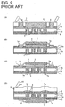
- Japanese Unexamined Patent Publication No. H09-148691 discloses, as shown in FIGS. 8(A), 8(B) and 8(C) , that a copper foil flat pattern 3 is provided one surface 2a of a double-sided circuit board 2 on which a heat generating element 1 is to be mounted, the underside of the heat generating element 1 is secured to the copper foil flat pattern 3 using solder or paste, the copper foil flat pattern 3 is electrically connected to a copper foil flat pattern 5 on another surface 2b through viaholes 4, and heat generated by the heat generating element 1 is radiated from the copper foil flat pattern 5 on the other surface 2b via the copper foil flat pattern 3 and viaholes 4.
- the heat generated by the heat generating element 1 is efficiently transferred to the copper foil flat pattern 5 from the copper foil flat pattern 3 through conductive layers 4a formed on the inner circumferential surfaces of the viaholes 4 by plating, thereby improving a heat radiating effect.
- Japanese Unexamined Patent Publication No. H09-148691 simply discloses that the heat generating element 1 is secured to the copper foil flat pattern 3 using paste, solder or the like, and a specific securing method using solder or paste is unclear.
- Japanese Unexamined Patent Publication No. 2004-127992 discloses that, after through holes are formed to penetrate a printed circuit board from the top surface to the under surface and the under surface is placed on a base plate, the through holes are filled up by printing resin paste in the through holes from the topside by means of a squeegee so as to prevent solder flowing into the through holes from forming protuberances at the underside.
- cream solder 7 is applied to land portions 6 solder-connected to lead terminals 1a of a heat generating element 1 on one surface 2a of a circuit board 2 and a copper foil flat pattern 3 for heat radiation as shown in FIG. 9A ; a first reflow process is carried out by heating the circuit board 2 with the heat generating element 1 placed on the upper surface thereof as shown in FIG. 9(B) ; and the lead terminals 1a of the heat generating element 1 and the underside of the heat generating element 1 are respectively solder-connected to the land portions 6 and the copper foil flat pattern 3.
- solder applied to the copper foil flat pattern 3 is melted to flow into the viaholes 4, spills out from the openings surrounded by a copper foil flat pattern 5 on an other surface 2b, and is solidified while bulging out at the openings, thereby forming the solder balls 7a as shown in FIG. 9C .
- a metal mask 9 is mounted and the cream solder is applied by a squeegee 10 as shown in FIG. 9(D) , but the metal mask 9 becomes uneven by the presence of the solder balls 7a.
- the cream solder when heated by a reflow process, it is separated into solder and flux for facilitating the soldering.
- This flux flows into the viaholes 4 together with the molten solder to adhere to the copper foil flat pattern 5 on the underside. Since this flux is adhesive, the metal mask becomes difficult to remove after the cream solder is applied with the metal mask mounted on the other surface side, which presents a problem of reducing operability.
- the European patent application EP 0 920 055 A2 discloses a cooling apparatus having a printed circuit board provided on a first face with at least one component which produces heat and is arranged on a first large-area metallization. Further, the printed circuit board has a second large-area metallization on a face opposite the component, which is thermally conductively connected in the mounting area of the component to the first large-area metallization via through-holes. On the face opposite the component a thermally conductive plate is soldered to that area of the second large-area metallization which is provided with the through-holes.
- German publication document DE 199 10 500 A1 discloses an electrical device comprising a printed circuit board located in a housing. Heat-generating electrical/electronic components are arranged one a first side of the printed circuit board. A plurality of plated through-holes electrically connect the first side with a second side of the printed circuit board, wherein heat sinks are arranged at the second side in the area of the through-holes. The remaining interior space of the housing is filled with a heat conducting, and electrically insulating sealing compound.
- the US patent application publication US 2002/0131240 A1 discloses a heat dissipation structure of an integrated circuit including a circuit board provided with a plurality of through holes.
- the heat generated from the IC is transmitted to a first portion of a solder made of metal, which is located under the IC.
- the transmitted heat is then transmitted to a second portion of the solder, which is located within the through-holes, and to a third portion of the solder, which is attached to solder lands on the through-holes of a lower surface of the circuit board.
- the third portion of the solder serves as a heat sink.
- Japanese patent application JP 2006-100483 A discloses a heat dissipation structure of a print wiring board.
- the printed wiring board with a circuit pattern formed at least on one surface thereof includes a heat dissipator of a heating component provided in the circuit pattern.
- the heat dissipator comprises a first heat dissipation pattern wherein the pattern of a part of the circuit pattern is expanded and formed to which an electrode of the heating component is connected.
- a second heat dissipation pattern has a size substantially coincident with the first heat dissipatation pattern, while facing the first heat dissipation pattern and formed on the other surface of the printed wiring board.
- a through hole penetrates the printed wiring board in a region where the first heat dissipation pattern and the second heat dissipation pattern are existent, and includes an electric conductor disposed on the internal peripheral surface of the printed wiring board to electrically connect the first heat dissipation pattern part and the second heat dissipation part.
- the present invention was developed in view of the above problems, and an object thereof is to improve the production process of a printed circuit board.
- solder flown into one or more viaholes is advantageously prevented from being formed into solder balls largely protuberant on an other surface, so that a metal mask does not become uneven and the metal mask and a squeegee used for cream application are not damaged at the time of mounting the metal mask to apply cream solder to land portions on the other surface.
- a method for producing a printed circuit board with at least one heat radiating structure comprising the steps of:
- the method further comprises forming one or more solder resists on solder unnecessary parts of the one surface of the printed circuit board to at least partly surround the soldering land portion for heat radiation.
- the first reflow process comprises forming a solder layer at least partly adhering to the soldering land portion for heat radiation and the underside of the electronic part.
- a method for producing a printed circuit board with a heat radiating structure comprising the steps of:
- the leaked-out solder spreads along the outer surface of the copper foil and deposits at the peripheries of the openings in a flat manner since the land portion for solder absorption is provided at these openings to expose the copper foil.
- the molten solder is solidified in a flat manner while surrounding the openings of the viaholes without becoming solder balls formed by the solidified solder protuberant at the openings of the viaholes.
- the metal mask when the metal mask is mounted on the other surface of this printed circuit board and the cream solder is applied, the metal mask is not deformed to become uneven since there are no largely protuberant solder balls.
- the cream solder is applied also to the land portion for solder absorption, the metal mask is formed with openings in a part corresponding to the land portion for solder absorption, wherefore the metal mask does not become uneven.
- the damage of a squeegee and the metal mask can be prevented in the process of applying the cream solder to the upper surface of the metal mask by the squeegee. Further, since the metal mask is not mounted on the land portion for solder absorption, there is no likelihood that the metal mask adheres because of flux and is made difficult to remove. In this way, problems that have occurred in the conventional production process can be solved, and production costs can be reduced by improving production efficiency in the production process.
- a thickness of the applied cream solder for the first reflow process is substantially equal to the thickness of the metal mask used in connection therewith.
- the molten solder at least partly leaking out toward the other surface through the one or more viaholes forms one or more solder deposited portions having a projecting height which is smaller than thickness of the metal mask used in connection with the second reflow process.
- the cream solder is applied at least to the land portion for solder absorption up to the substantially same height as the metal mask while preferably at least partly covering solder deposited portions on or near the openings of the one or more respective viaholes.
- a heat radiating structure for a printed circuit board wherein:
- the heat radiating structure for the printed circuit board according to the above is preferably produced by the producing method according to the invention or a preferred embodiment thereof.
- the land portion for solder absorption at least partly substantially faces the soldering land portion for heat radiation in the thickness direction of the printed circuit board while preferably having substantially the same area as the soldering land portion for heat radiation.
- a plurality of viaholes are arranged at specified (predetermined or predeterminable) intervals in forward and backward directions and/or transverse direction, and that the outer edge of the land portion for solder absorption is at a specified distance from the viaholes located at the outer ends in forward and backward direction and/or transverse direction.
- the land portion for solder absorption has such a wide area including the openings of all the viaholes and the outer edge thereof is at the specified distance from the openings of the viaholes located closest to this outer edge as described, the molten solder and flux leaking out from the openings of the viaholes can be reliably prevented from adhering to the outer surface of the solder resist at the outer periphery.
- one or more lead terminals projecting from the outer side surface of the electronic part are respectively solder-connected to one or more respective land portions provided on the one surface of the printed circuit board and the electronic part includes a heat radiating member formed of a radiation slug or heat sink on the underside thereof, and the solder layer preferably formed on the soldering land portion for heat radiation is secured in surface contact with the heat radiating member.
- the heat radiating member can be reliably brought substantially into surface contact with the solder layer formed on the outer surface of the soldering land portion for heat radiation, wherefore the heat radiating property of the electronic part can be reliably improved.
- the soldering land portion for heat radiation is provided at the underside of the electronic part generating heat and the land portion for solder absorption is provided on the other surface electrically connected to the soldering land portion through the viaholes.
- FIGS. 1 to 7 one preferred embodiment of the present invention is described with reference to FIGS. 1 to 7 .
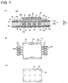
- FIGS. 1(A) to 1(C) show a printed circuit board 100.
- the printed circuit board 100 preferably is a double-sided circuit board having one or more conductor patterns 13 (13A, 13B) made of conductive material, preferably conductive foil material such as copper foil on one and/or other surfaces 12a, 12b of an insulating substrate 12 made of insulating material such as glass epoxy, and an electronic part 20 including an IC chip, to which preferably a large current is or can be applied, is mounted or mountable on the one surface 12a.
- conductor patterns 13 13A, 13B
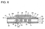
- the plurality of lead terminals 20b, 20c project from (preferably the bottom ends or edges of) the (preferably substantially opposite) lateral (left and/or right) surface(s) of a case 20a of the electronic part 20, and a heat sink 21 is attached to a mounting side to be oriented facing towards the printed circuit board 100 or the one surface 12 a (preferably to the underside or lower surface) of the electronic part 20.
- the lead terminals 20b, 20c of the electronic part 20 are to be electrically connected, preferably solder-connected to one or more land portions 16, 17 of the one or more conductor patterns on the one surface 12a, thereby mounting the electronic part 20 on the one surface 12a.
- the copper foil is at least partly exposed by providing a connecting portion, preferably a soldering land portion 22, for heat radiation surrounded by a solder resist 18.
- One or more, preferably a plurality of viaholes or conductive through holes 24 (particularly holes at least partly having a conductive inner surface, such as by plating, which are not (predominantly) used as component holes but serve as interlayer connections and/or for connecting conductive layers or patterns on two surfaces particularly like "Through Hole Plated" (THPlated)) each having a one-end opening in or close to this soldering land portion 22 for heat radiation are formed preferably substantially in a substantially regular patter or a matrix array at the substantially same intervals in forward and backward directions and/or transverse direction.
- THPlated Thine Plated
- viaholes 24 are arranged in transverse direction and three are arranged in forward and backward directions, thereby providing a total of twelve viaholes 24. It should be noted that the number of the viaholes 24 can be suitably selected according to the size of the electronic part 20 and/or the heat to be dissipated.
- the conductive foil (preferably the copper foil) is at least partly exposed by providing at least one land portion 25 for solder absorption preferably having substantially the same area as the soldering land portion 22 for heat radiation and/or preferably substantially facing the soldering land portion 22 in thickness direction TD, and the exposed part is at least partly surrounded by a solder resist 26.
- the outer periphery of the land portion 25 for solder absorption determined by the solder resist 26 is at a specified (predetermined or predeterminable) distance L from the viaholes 24 closest to this outer periphery.
- the land portion 25 for solder absorption and the soldering land portion 22 for heat radiation have substantially the same rectangular shape as the outer shape of the case 20a of the electronic part 20.
- a solder layer 27 preferably formed by reflowing the cream solder is provided between the soldering land portion 22 for heat radiation and/or the heat sink 21 on the side where the electronic part 20 is to be mounted. Further, the solder molten during the reflowing at least partly flows into hollow parts enclosed by conductive layers 28 (preferably formed by plating) on the inner circumferential surfaces of the viaholes 24 making openings in the soldering land portion 22 for heat radiation, whereby these hollow parts are at least partly filled with solder 30.
- This solder 30 at least partly flows or can flow out from the openings 24b of the viaholes 24 on the other surface and can spread at least partly along the copper foil surface of the land portion 25 for solder absorption to become substantially flat (in particular such that the lateral extension is at least about three times more than the height extension, more preferably at least about four times, most preferably at least about five times) and low mountain-shaped solder deposited portions 31.
- a solder layer 32 is provided on the land portion 25 for solder absorption by applying the cream solder in such a manner as to cover the solder deposited portions 31 and/or reflowing the cream solder.
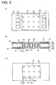
- one or more through holes to become the viaholes are formed at specified (predetermined or predeterminable) positions of a copper-clad laminate, in which copper foils are provided as preferred conductive foils on the both surfaces of the insulating substrate 12 made of insulating material such as glass epoxy, preferably by means of a drill, a laser cutting tool or the like, and the conductive layers 28 are at least partly formed on the inner circumferential surfaces of these through holes preferably by plating to form the one or more viaholes 24.
- the one or more conductive (preferably copper) foil patterns 13A, 13B are formed to have specified (predetermined or predeterminable) circuit configurations on the both surfaces 12a, 12b of the circuit board preferably by etching.
- the one or more solder resists 18, 26 are formed on the (preferably both) surface(s) 12a, 12b while preferably leaving the soldering portions, thereby attaining a state shown in FIGS. 2(A) to 2(C) .
- the (preferably substantially rectangular) soldering land portion 22 for heat radiation where the one-end openings 24a of a plurality of viaholes 24 are, is at least partly formed in a part to substantially face a placing portion of the electronic part 20 on the one surface 12a where the electronic part 20 is to be mounted, and the soldering land portion 22 for heat radiation is at least partly, preferably substantially fully surrounded by the solder resist 18.
- the copper foils of the land portions 16, 17 for solder connection with the lead terminals of the electronic part 20 are at least partly exposed at the (preferably substantially opposite) lateral (left and/or right) side(s) of the soldering land portion 22 for heat radiation.
- the land portion 25 for at least partial solder absorption including all the other-end openings 24b of the viaholes 24 is formed on the other surface 12b while being at least partly, preferably substantially fully surrounded by the solder resist 26.
- the land portion 25 for solder absorption preferably is formed to have the substantially same shape as the soldering land portion 22 for heat radiation while substantially facing the soldering land portion 22 in the thickness direction TD of the insulating substrate 12.
- a metal mask 35 is mounted to expose substantially only the soldering portion on the one surface 12a where the electronic part 20 is to be mounted.
- the metal mask 35 has one or more openings 35a in its surface substantially facing parts where the solder resist 18 is not provided, i.e. the soldering land portion 22 for heat radiation and the land portions 16, 17.
- cream solder 36 is put on one side of the outer surface of the metal mask 35 and applied to the outer surface of the metal mask 35 by a squeegee or resilient scraping tool 38.
- the cream solder 36 is at least partly applied to the outer surface(s) of the soldering land portion 22 for heat radiation and/or the land portions 16, 17 at or near the openings 35a.
- the thickness of the applied cream solder 36 preferably is substantially equal to the thickness of the metal mask 35.
- the metal mask 35 is removed after the cream solder 36 is applied.
- the electronic part 20 is placed, the leading terminals 20b, 20c thereof are brought substantially into contact with the cream solder 36 on the outer surfaces of the land portions 16, 17, and the heat sink 21 on the underside of the electronic part 20 is brought or bringable into contact with the outer surface of the cream solder 36 at least partly applied on the outer surface of the soldering land portion 22 for heat radiation.
- heating is performed at a specified (predetermined or predeterminable) temperature using heating means (not shown) to melt the cream solder 36, thereby performing a first reflow process.
- the one or more lead terminals 20b, 20c of the electronic part 20 are solder-connected or - connectable to the land portions 16, 17 using the solder in the cream solder 36 as shown in FIG. 6 .
- the cream solder 36 at least partly applied on the soldering land portion 22 for heat radiation is substantially melted to adhere or contact to the heat sink 21 and the copper foil of the soldering land portion 22 for heat radiation. Thereafter, the cream solder 36 is solidified to become the solder layers 27 preferably upon being taking out from a reflow oven.
- the molten cream solder 36 flows at least partly into the hollow parts of part or all the viaholes 24 at least partly exposed at the soldering land portion 22 for heat radiation, at least partly fills up the hollow parts while substantially adhering to the conductive layers 28 on the inner circumferential surfaces, and are thereafter solidified to become the solders 30.
- the molten solder flown into the viaholes 24 may also at least partly flow out from the openings 24b at the land portion 25 for solder absorption, but at least partly spreads along the copper foil since the copper foil is exposed on the surface of the land portion 25 for solder absorption.
- the molten solder at least partly spreads to form flat mountain-shaped projections about the openings 24b instead of becoming protuberant solder balls as in the prior art.
- the flat solder deposited portions 31 are formed at the openings of the viaholes 24 at the land portion 25 for solder absorption.
- the height of the solder deposited portions 31 preferably is smaller than thickness "t" of a metal mask 40 to be described later.
- the metal mask 40 is mounted substantially on or near the other surface 12b of the printed circuit board 12 and cream solder 41 is applied preferably by the squeegee 38.
- the metal mask 40 Since the metal mask 40 has an opening 40a in its part facing the land portion 25 for solder absorption, and the height of the solder deposited portions 31 is shorter than the height of the metal mask 40, the metal mask 40 can cover in a flat state substantially without becoming uneven due to solder balls as in the prior art. Thus, the cream solder 41 can be smoothly applied without damaging the metal mask 40 and squeegee 38 in the process of applying the cream solder 41 by the squeegee 38.
- the cream solder 41 is applied to the land portion 25 for solder absorption preferably up to the substantially same height as the metal mask 40 while covering the solder deposited portions 31 centered on the openings 24b of the respective viaholes 24.
- flux F leaks out to the outer surfaces of the solder deposited portions 31, it is substantially embedded in the cream solder 41 and does not leak out to the outer surface of the cream solder 41.
- the metal mask 40 is removed after the application of the cream solder 41. At this time, the flux F substantially does not come into contact with the metal mask 40 since the metal mask 40 has the opening and the solder deposited portions 31 are substantially embedded in the cream solder 41.
- a second reflow process is carried out using the heating means to melt the cream solder 41, whereby the cream solder 41 is secured to the solder deposited portions 31 of the land portion 25 for solder absorption and the copper foil of the land portion 25 for solder absorption and is, thereafter, solidified to form the solder layer 32.
- the land portion 25 for solder absorption connected to the soldering land portion 22 for heat radiation on the mounting surface for the electronic part 20 through the one or more viaholes 24 is provided on the other surface, the molten solder flown out to the other surface from the viaholes 24 can at least partly spread substantially along the copper foil surface of the land portion 25 for solder absorption, thereby being able to prevent the formation of the solder balls projecting from the other surface.
- the land portion 25 for solder absorption is provided in a part where the molten solder flows out from the viaholes 24, the metal mask 40 to be mounted on the solder resist 26 on the other surface has the opening in its part facing the land portion 25 for solder absorption and, hence, the metal mask 40 is not mounted on the solder deposited portions 31 formed by the flown-out and solidified solder.
- the damage of the metal mask 40 and squeegee 38 can be prevented at the time of applying the cream solder 41 to the outer surface of the metal mask 40 by the squeegee 38, wherefore production efficiency can be improved.
- a printed circuit board with a heat radiating structure having a solder layer for heat radiation at one side of an electronic part for radiating heat toward an other surface side through viaholes, which can prevent problems at the time of production caused by solder balls formed at openings of viaholes at the other surface.
- a soldering land portion for heat radiation is provided in a part, which serves as a mounting surface for an electronic part, a land portion for solder absorption is formed on the other surface facing the mounting surface, and viaholes are provided which makes openings in the soldering land portion for heat radiation and the land portion for solder absorption at the opposite ends.
- Molten solder flowing out from the openings of the viaholes is caused to spread on the land portion for solder absorption, thereby suppressing the formation of solder balls, and cream solder is applied to the outer surface of the land portion for solder absorption in such a manner as to embed the solder, thereby forming a solder layer.
- a soldering land portion may be provided in an area surrounded by land portions solder-connected to the lead terminals with the outer periphery thereof determined by a solder resist
- an area of the land portion for solder absorption on the other surface may be made larger than that of the soldering land portion for heat radiation as long as such an enlargement is possible in terms of space. In such a case, heat radiation capability can be further improved.
- the land portion for solder absorption having a large area may double as a ground circuit or a power supply circuit.
Claims (6)
- Ein Verfahren zur Herstellung einer gedruckten Schaltungsplatine bzw. Leiterplatte (100) mit mindestens einer Wärme abstrahlenden Struktur, das die folgenden Schritte umfasst:vorbereiten einer Leiterplatte (100), die ein oder mehrere Leitermuster (13) aufweist und einen oder mehrere Kontaktflächenabschnitte (land portions) (16; 17), die aus einer leitfähigen Folie hergestellt werden, die auf einer oder beiden Oberflächen (12a; 12b) eines isolierenden Substrats (12) gebildet wird, das mindestens einen Löt-Kontaktflächenabschnitt (22) zur Wärmeabstrahlung aufweist, der auf einem Teil einer Oberfläche gebildet ist, um als Montagefläche für ein elektronisches Bauteil (20) zu dienen, und mindestens ein Kontaktflächenabschnitt (25) zur Lötmittelabsorption, der auf der anderen Fläche (12b) gebildet wird, die der einen Fläche (12a) im Wesentlichen gegenüberliegt und mit einem oder mehreren Durchgangslöchern (24) gebildet wird, deren gegenüberliegenden Enden Öffnungen (24a, 24b) im Löt-Kontaktflächenabschnitt (22) zur Wärmeabstrahlung realisieren, und den Kontaktflächenabschnitt (25) zur Lötmittelaufnahme,platzieren einer Metallmaske (35) auf die eine Oberfläche (12a) und anbringen von Weichlotpaste (36) an einen oder mehreren Kontaktflächenabschnitten (16; 17) und einen Löt-Kontaktflächenabschnitt (22) zur Wärmeabstrahlung,platzieren des elektronischen Bauteils (20) im Wesentlichen auf die eine Oberfläche, schmelzen der Weichlotpaste (36) in einem ersten Reflow-Prozess, um Leiteranschlüsse (20b; 20c) des elektronischen Bauteils (20) und entsprechend den einen oder die mehreren Kontaktflächenabschnitte (16; 17) durch Löten zu verbinden, was bewirkt, dass zumindest ein Teil des geschmolzenen Lots zur anderen Oberfläche (12b) durch das eine oder die mehreren Durchgangslöcher (24) nach außen dringt, um zumindest teilweise zum Kontaktflächenabschnitt (25) zur Lötmittelabsorption zu fließen und im Wesentlichen an den oder in der Nähe der Öffnungen (24b) auf im Wesentlichen flache Weise haften zu bleiben, undplatzieren einer Metallmaske (40) auf die andere Oberfläche (12b) der Leiterplatte (100), anbringen von Weichlotpaste (41) an den Kontaktflächenabschnitt (25) zur Lötmittelabsorption, sodass das verfestigte Lot an den oder in der Nähe der Öffnungen (24b) der Durchgangslöcher (24) bedeckt wird und die Weichlotpaste (41) wird in einem zweiten Reflow-Prozess geschmolzen, um eine Lotschicht (32) auf dem Kontaktflächenabschnitt (25) zur Lötmittelabsorption zu bilden,wobei der Platzierungs-Schritt der Metallmaske (40) auf die andere Oberfläche (12b) der Leiterplatte (100) Folgendes umfasst:bereitstellen der Metallmaske (40) auf der anderen Oberfläche (12b) mit einer Öffnung in einem Teil, die dem Kontaktflächenabschnitt (25) zur Lötmittelabsorption zugewandt ist, einschließlich der Öffnungen (24b) des einen oder der mehreren Durchgangslöcher (24), undmontieren der genannten Metallmaske (40) auf einem Lötresist (26), der den Kontaktflächenabschnitt (25) zur Lötmittelabsorption umgibt,wobei kein Wärme abstrahlendes Element an den Kontaktflächenabschnitt (25) zur Lötmittelabsorption durch die Lotschicht (32) auf den Kontaktflächenabschnitt (25) zur Lötmittelabsorption während des zweiten Reflow-Prozesses angelötet wird.
- Ein Verfahren nach Anspruch 1, das des Weiteren die Bildung eines oder mehrerer Lötresists (18) auf Teilen der einen Oberfläche der Leiterplatte (100) umfasst, auf denen eine Lötung nicht notwendig ist, um zumindest teilweise den Löt-Kontaktflächenabschnitt (22) zur Wärmeabstrahlung zu umgeben.
- Ein Verfahren nach einem oder mehreren der vorhergehenden Ansprüche, wobei der erste Reflow-Prozess die Bildung einer Lotschicht umfasst, die zumindest teilweise am Löt-Kontaktflächenabschnitt (22) zur Wärmeabstrahlung anhaftet und an der Unterseite des elektronischen Bauteils (20).
- Ein Verfahren nach einem oder mehreren der vorhergehenden Ansprüche, wobei eine Dicke der aufgebrachten Weichlotpaste (36) für den ersten Reflow-Prozess mit der Dicke der Metallmaske (35), die in diesem Zusammenhang verwendet wird, im Wesentlichen gleich ist.
- Ein Verfahren nach einem oder mehreren der vorhergehenden Ansprüche, wobei das geschmolzene Lot (36), das zumindest teilweise zur anderen Oberfläche durch das eine oder die mehreren Durchgangslöcher (24) nach außen tritt, einen oder mehrere Abschnitte mit aufgebrachtem Lot (solder deposited portions) (31) bildet, die eine vorstehende Höhe aufweisen, die geringer ist als die Dicke (t) der Metallmaske (40) ist, die im Zusammenhang mit dem zweiten Reflow-Prozess verwendet wird.
- Ein Verfahren nach einem oder mehreren der vorhergehenden Ansprüche, wobei die Weichlotpaste (41), im Zusammenhang mit dem zweiten Reflow-Prozess, zumindest auf den Kontaktflächenabschnitt (25) zur Lötmittelabsorption bis hin zur im Wesentlichen gleichen Höhe aufgebracht wird, wie die Metallmaske (40) wobei vorzugsweise zumindest teilweise Abschnitte mit aufgebrachtem Lot (31) an oder in der Nähe der Öffnungen (24b) des einen oder der mehreren Durchgangslöcher (24) abgedeckt werden.
Applications Claiming Priority (1)
| Application Number | Priority Date | Filing Date | Title |
|---|---|---|---|
| JP2006253993A JP5142119B2 (ja) | 2006-09-20 | 2006-09-20 | 放熱構造を備えたプリント基板の製造方法および該方法で製造されたプリント基板の放熱構造 |
Publications (3)
| Publication Number | Publication Date |
|---|---|
| EP1903839A2 EP1903839A2 (de) | 2008-03-26 |
| EP1903839A3 EP1903839A3 (de) | 2009-05-27 |
| EP1903839B1 true EP1903839B1 (de) | 2016-04-20 |
Family
ID=38814319
Family Applications (1)
| Application Number | Title | Priority Date | Filing Date |
|---|---|---|---|
| EP07018384.3A Expired - Fee Related EP1903839B1 (de) | 2006-09-20 | 2007-09-19 | Verfahren zur Herstellung einer Leiterplatte mit einer wärmeabstrahlenden Struktur |
Country Status (3)
| Country | Link |
|---|---|
| US (1) | US7606038B2 (de) |
| EP (1) | EP1903839B1 (de) |
| JP (1) | JP5142119B2 (de) |
Families Citing this family (40)
| Publication number | Priority date | Publication date | Assignee | Title |
|---|---|---|---|---|
| US8425085B2 (en) * | 2006-04-16 | 2013-04-23 | Albeo Technologies, Inc. | Thermal management of LED-based lighting systems |
| US7806574B2 (en) * | 2006-04-16 | 2010-10-05 | Albeo Technologies, Inc. | Thermal management of LED-based lighting systems |
| JP5070014B2 (ja) * | 2007-11-21 | 2012-11-07 | 株式会社豊田自動織機 | 放熱装置 |
| JP2009130060A (ja) * | 2007-11-21 | 2009-06-11 | Toyota Industries Corp | 放熱装置 |
| US8981629B2 (en) | 2008-08-26 | 2015-03-17 | Albeo Technologies, Inc. | Methods of integrating LED chips with heat sinks, and LED-based lighting assemblies made thereby |
| US9076951B2 (en) | 2008-08-26 | 2015-07-07 | Albeo Technologies, Inc. | Methods of integrating LED chips with heat sinks, and LED-based lighting assemblies made thereby |
| US8058659B2 (en) | 2008-08-26 | 2011-11-15 | Albeo Technologies, Inc. | LED chip-based lighting products and methods of building |
| KR100962706B1 (ko) * | 2009-11-27 | 2010-06-15 | 주식회사 테크엔 | 파워 led를 갖는 대형 조명등의 제조 방법 |
| JP5546889B2 (ja) | 2010-02-09 | 2014-07-09 | 日本電産エレシス株式会社 | 電子部品ユニット及びその製造方法 |
| US8411444B2 (en) * | 2010-09-15 | 2013-04-02 | International Business Machines Corporation | Thermal interface material application for integrated circuit cooling |
| US20120068218A1 (en) * | 2010-09-17 | 2012-03-22 | Taiwan Semiconductor Manufacturing Company, Ltd. | Thermally efficient packaging for a photonic device |
| EP2447990B1 (de) * | 2010-11-02 | 2020-12-23 | ABB Power Grids Switzerland AG | Grundplatte |
| US8772817B2 (en) | 2010-12-22 | 2014-07-08 | Cree, Inc. | Electronic device submounts including substrates with thermally conductive vias |
| JP2012227349A (ja) * | 2011-04-19 | 2012-11-15 | Hitachi Ltd | 電子部品の実装方法 |
| DE102011088256A1 (de) * | 2011-12-12 | 2013-06-13 | Zf Friedrichshafen Ag | Multilayer-Leiterplatte sowie Anordnung mit einer solchen |
| JP5939102B2 (ja) * | 2012-09-18 | 2016-06-22 | 富士通株式会社 | 電子機器 |
| JP5885630B2 (ja) * | 2012-09-21 | 2016-03-15 | 三菱電機株式会社 | プリント基板 |
| JP6147990B2 (ja) * | 2012-11-13 | 2017-06-14 | Necプラットフォームズ株式会社 | 表面実装構造体および表面実装方法 |
| JP6079461B2 (ja) * | 2013-06-12 | 2017-02-15 | 富士通株式会社 | 伝熱構造板、伝熱構造板モジュール及び海中機器 |
| US9801277B1 (en) | 2013-08-27 | 2017-10-24 | Flextronics Ap, Llc | Bellows interconnect |
| US9565748B2 (en) * | 2013-10-28 | 2017-02-07 | Flextronics Ap, Llc | Nano-copper solder for filling thermal vias |
| US9674952B1 (en) | 2013-12-30 | 2017-06-06 | Flextronics Ap, Llc | Method of making copper pillar with solder cap |
| JPWO2016157478A1 (ja) * | 2015-04-01 | 2017-07-06 | 三菱電機株式会社 | 配線基板および電子装置 |
| KR102411999B1 (ko) * | 2015-04-08 | 2022-06-22 | 삼성전기주식회사 | 회로기판 |
| CN104955265A (zh) * | 2015-05-26 | 2015-09-30 | 苏州旭创科技有限公司 | Pcb基板及具有其的光模块 |
| KR102538908B1 (ko) * | 2015-09-25 | 2023-06-01 | 삼성전기주식회사 | 인쇄회로기판 및 그 제조방법 |
| JP6912157B2 (ja) * | 2015-11-26 | 2021-07-28 | 株式会社藤商事 | 遊技機 |
| JP6783515B2 (ja) * | 2015-11-26 | 2020-11-11 | 株式会社藤商事 | 遊技機 |
| JP7032034B2 (ja) * | 2015-11-26 | 2022-03-08 | 株式会社藤商事 | 遊技機 |
| EP3522340B1 (de) | 2016-09-28 | 2023-10-18 | Mitsubishi Electric Corporation | Elektromotor, gebläse, klimaanlage und verfahren zur herstellung eines elektromotors |
| CN107960004A (zh) * | 2016-10-14 | 2018-04-24 | 鹏鼎控股(深圳)股份有限公司 | 可伸缩电路板及其制作方法 |
| WO2018216646A1 (ja) * | 2017-05-26 | 2018-11-29 | 三菱電機株式会社 | 半導体装置 |
| AT520301B1 (de) | 2017-10-12 | 2019-03-15 | Zkw Group Gmbh | Verfahren zum erzeugen einer leiterplatte mit thermischen durchkontaktierungen, sowie leiterplatte |
| CN111433909B (zh) * | 2017-12-14 | 2023-08-11 | 三菱电机株式会社 | 半导体装置 |
| JP7107810B2 (ja) * | 2018-10-19 | 2022-07-27 | 株式会社ソニー・インタラクティブエンタテインメント | 半導体装置の製造方法およびスクリーン |
| JP7250474B2 (ja) * | 2018-10-19 | 2023-04-03 | 株式会社ソニー・インタラクティブエンタテインメント | 電源装置 |
| JP6835788B2 (ja) | 2018-10-19 | 2021-02-24 | 株式会社ソニー・インタラクティブエンタテインメント | 電源装置 |
| US11528808B2 (en) * | 2018-12-03 | 2022-12-13 | X Display Company Technology Limited | Printing components to substrate posts |
| US11189543B2 (en) * | 2019-07-31 | 2021-11-30 | Microchip Technology Caldicot Limited | Board assembly with chemical vapor deposition diamond (CVDD) windows for thermal transport |
| CN218514579U (zh) * | 2022-08-22 | 2023-02-21 | 北京比特大陆科技有限公司 | 电路板及电子设备 |
Citations (4)
| Publication number | Priority date | Publication date | Assignee | Title |
|---|---|---|---|---|
| US5708566A (en) * | 1996-10-31 | 1998-01-13 | Motorola, Inc. | Solder bonded electronic module |
| JP2004127992A (ja) * | 2002-09-30 | 2004-04-22 | Ngk Spark Plug Co Ltd | 配線基板の製造方法 |
| JP2005340233A (ja) * | 2004-05-24 | 2005-12-08 | Hitachi Kokusai Electric Inc | 電子回路基板 |
| JP2006100483A (ja) * | 2004-09-29 | 2006-04-13 | Matsushita Electric Works Ltd | プリント配線板の放熱構造 |
Family Cites Families (32)
| Publication number | Priority date | Publication date | Assignee | Title |
|---|---|---|---|---|
| GB8324839D0 (en) * | 1983-09-16 | 1983-10-19 | Lucas Ind Plc | Mounting carrier for microelectronic silicon chip |
| JPS6398675A (ja) | 1986-10-16 | 1988-04-30 | Toshiba Corp | 電子複写機の現像装置 |
| JPH0211391A (ja) | 1988-06-30 | 1990-01-16 | Canon Inc | 記録媒体の製造方法 |
| JPH04137691A (ja) | 1990-09-28 | 1992-05-12 | Toshiba Lighting & Technol Corp | 回路基板 |
| JPH06268341A (ja) | 1993-03-15 | 1994-09-22 | Hitachi Ltd | 電子部品の放熱方法、および同放熱構造 |
| JPH08204322A (ja) * | 1995-01-26 | 1996-08-09 | Ibiden Co Ltd | バンプの形成方法 |
| JPH0955459A (ja) * | 1995-06-06 | 1997-02-25 | Seiko Epson Corp | 半導体装置 |
| JP3269397B2 (ja) * | 1995-09-19 | 2002-03-25 | 株式会社デンソー | プリント配線基板 |
| JPH1168262A (ja) | 1997-08-08 | 1999-03-09 | Nec Home Electron Ltd | 電子部品の放熱構造及びその製造方法 |
| DE19736962B4 (de) * | 1997-08-25 | 2009-08-06 | Robert Bosch Gmbh | Anordnung, umfassend ein Trägersubstrat für Leistungsbauelemente und einen Kühlkörper sowie Verfahren zur Herstellung derselben |
| DE19752797A1 (de) * | 1997-11-28 | 1999-06-10 | Bosch Gmbh Robert | Kühlvorrichtung für ein auf einer Leiterplatte angeordnetes, wärmeerzeugendes Bauelement |
| DE19909505C2 (de) * | 1999-03-04 | 2001-11-15 | Daimler Chrysler Ag | Verfahren zur Herstellung von Schaltungsanordnungen |
| DE19910500A1 (de) * | 1999-03-10 | 2000-10-05 | Bosch Gmbh Robert | Elektrisches Gerät |
| JP3573034B2 (ja) * | 1999-11-17 | 2004-10-06 | 日本電気株式会社 | 多層プリント配線板およびその放熱構造 |
| JP2001168476A (ja) | 1999-12-14 | 2001-06-22 | Aisin Seiki Co Ltd | 回路基板上での放熱構造 |
| US6373348B1 (en) * | 2000-08-11 | 2002-04-16 | Tektronix, Inc. | High speed differential attenuator using a low temperature co-fired ceramic substrate |
| US6867493B2 (en) * | 2000-11-15 | 2005-03-15 | Skyworks Solutions, Inc. | Structure and method for fabrication of a leadless multi-die carrier |
| JP2002192688A (ja) | 2000-12-25 | 2002-07-10 | Ibiden Co Ltd | 半田印刷方法 |
| KR20020074073A (ko) * | 2001-03-16 | 2002-09-28 | 엘지전자 주식회사 | 아이씨 방열구조 |
| US7259448B2 (en) * | 2001-05-07 | 2007-08-21 | Broadcom Corporation | Die-up ball grid array package with a heat spreader and method for making the same |
| JP2003289191A (ja) * | 2002-03-28 | 2003-10-10 | Denso Corp | 電子制御装置 |
| JP2003318579A (ja) * | 2002-04-24 | 2003-11-07 | Toyoda Mach Works Ltd | 放熱板付きfetの放熱方法 |
| US6977346B2 (en) * | 2002-06-10 | 2005-12-20 | Visteon Global Technologies, Inc. | Vented circuit board for cooling power components |
| JP3804861B2 (ja) * | 2002-08-29 | 2006-08-02 | 株式会社デンソー | 電気装置および配線基板 |
| US6770967B2 (en) * | 2002-12-23 | 2004-08-03 | Eastman Kodak Company | Remote thermal vias for densely packed electrical assemblage |
| JP2005026457A (ja) * | 2003-07-02 | 2005-01-27 | Toshiba Corp | 電子部品実装方法、基板製造装置および回路基板 |
| JP2005340684A (ja) * | 2004-05-31 | 2005-12-08 | Calsonic Kansei Corp | 基板への電子素子の取付構造 |
| JP2006024755A (ja) * | 2004-07-08 | 2006-01-26 | Fujitsu Ltd | 回路基板 |
| US7269017B2 (en) * | 2004-11-19 | 2007-09-11 | Delphi Technologies, Inc. | Thermal management of surface-mount circuit devices on laminate ceramic substrate |
| US7148554B2 (en) * | 2004-12-16 | 2006-12-12 | Delphi Technologies, Inc. | Discrete electronic component arrangement including anchoring, thermally conductive pad |
| JP2006261255A (ja) * | 2005-03-16 | 2006-09-28 | Matsushita Electric Ind Co Ltd | 半導体装置 |
| US7510108B2 (en) * | 2005-07-26 | 2009-03-31 | Delphi Technologies, Inc. | Method of making an electronic assembly |
-
2006
- 2006-09-20 JP JP2006253993A patent/JP5142119B2/ja not_active Expired - Fee Related
-
2007
- 2007-09-19 EP EP07018384.3A patent/EP1903839B1/de not_active Expired - Fee Related
- 2007-09-20 US US11/903,154 patent/US7606038B2/en not_active Expired - Fee Related
Patent Citations (4)
| Publication number | Priority date | Publication date | Assignee | Title |
|---|---|---|---|---|
| US5708566A (en) * | 1996-10-31 | 1998-01-13 | Motorola, Inc. | Solder bonded electronic module |
| JP2004127992A (ja) * | 2002-09-30 | 2004-04-22 | Ngk Spark Plug Co Ltd | 配線基板の製造方法 |
| JP2005340233A (ja) * | 2004-05-24 | 2005-12-08 | Hitachi Kokusai Electric Inc | 電子回路基板 |
| JP2006100483A (ja) * | 2004-09-29 | 2006-04-13 | Matsushita Electric Works Ltd | プリント配線板の放熱構造 |
Also Published As
| Publication number | Publication date |
|---|---|
| US7606038B2 (en) | 2009-10-20 |
| JP2008078271A (ja) | 2008-04-03 |
| US20080186682A1 (en) | 2008-08-07 |
| JP5142119B2 (ja) | 2013-02-13 |
| EP1903839A2 (de) | 2008-03-26 |
| EP1903839A3 (de) | 2009-05-27 |
Similar Documents
| Publication | Publication Date | Title |
|---|---|---|
| EP1903839B1 (de) | Verfahren zur Herstellung einer Leiterplatte mit einer wärmeabstrahlenden Struktur | |
| US6284353B1 (en) | Printed wiring board and method of manufacturing the same | |
| JP3639505B2 (ja) | プリント配線基板及び半導体装置 | |
| US6922339B2 (en) | Heat dissipating structure of printed circuit board and fabricating method thereof | |
| CN100417310C (zh) | 具有散热元件的印刷电路板,其制作方法和包含它的器件 | |
| US5055637A (en) | Circuit boards with recessed traces | |
| US8319116B2 (en) | Rib reinforcement of plated thru-holes | |
| JP6021504B2 (ja) | プリント配線板、プリント回路板及びプリント回路板の製造方法 | |
| WO2006076101A2 (en) | A method to manufacture a universal footprint for a package with exposed chip | |
| CN101166394A (zh) | 安装有电子元件的多层配线基板及其制造方法 | |
| JP2002026187A (ja) | 半導体パッケージ及び半導体パッケージの製造方法 | |
| US20100236823A1 (en) | Ring of power via | |
| KR101068539B1 (ko) | 전해 도금을 이용한 배선 기판의 제조 방법 | |
| JPH08307028A (ja) | 回路カード及びその製造方法 | |
| CN110933850A (zh) | 一种高散热双面夹芯铜基印制电路板的制作方法 | |
| US11284502B2 (en) | Thermal relief for through-hole and surface mounting | |
| KR100873835B1 (ko) | 프린트배선판 및 그 제조방법 | |
| JP2003318579A (ja) | 放熱板付きfetの放熱方法 | |
| CN110931447A (zh) | 模块及印刷基板 | |
| US11711885B2 (en) | Method of manufacturing printed circuit board assemblies with engineered thermal paths | |
| CN100455162C (zh) | 电路板的制造方法 | |
| EP2239767A1 (de) | Verpackung für ein Halbleiterbauelement und deren Herstellung | |
| JP3700922B2 (ja) | 金属ベース配線板及びその製造方法 | |
| JP2002171041A (ja) | プリント配線板および電子部品およびその製造方法 | |
| JP4635329B2 (ja) | 配線回路基板の製造方法 |
Legal Events
| Date | Code | Title | Description |
|---|---|---|---|
| PUAI | Public reference made under article 153(3) epc to a published international application that has entered the european phase |
Free format text: ORIGINAL CODE: 0009012 |
|
| 17P | Request for examination filed |
Effective date: 20070927 |
|
| AK | Designated contracting states |
Kind code of ref document: A2 Designated state(s): AT BE BG CH CY CZ DE DK EE ES FI FR GB GR HU IE IS IT LI LT LU LV MC MT NL PL PT RO SE SI SK TR |
|
| AX | Request for extension of the european patent |
Extension state: AL BA HR MK YU |
|
| PUAL | Search report despatched |
Free format text: ORIGINAL CODE: 0009013 |
|
| AK | Designated contracting states |
Kind code of ref document: A3 Designated state(s): AT BE BG CH CY CZ DE DK EE ES FI FR GB GR HU IE IS IT LI LT LU LV MC MT NL PL PT RO SE SI SK TR |
|
| AX | Request for extension of the european patent |
Extension state: AL BA HR MK RS |
|
| 17Q | First examination report despatched |
Effective date: 20090715 |
|
| AKX | Designation fees paid |
Designated state(s): DE |
|
| GRAP | Despatch of communication of intention to grant a patent |
Free format text: ORIGINAL CODE: EPIDOSNIGR1 |
|
| RIC1 | Information provided on ipc code assigned before grant |
Ipc: H05K 1/02 20060101AFI20151111BHEP Ipc: H05K 3/34 20060101ALI20151111BHEP |
|
| INTG | Intention to grant announced |
Effective date: 20151125 |
|
| GRAS | Grant fee paid |
Free format text: ORIGINAL CODE: EPIDOSNIGR3 |
|
| GRAA | (expected) grant |
Free format text: ORIGINAL CODE: 0009210 |
|
| AK | Designated contracting states |
Kind code of ref document: B1 Designated state(s): DE |
|
| REG | Reference to a national code |
Ref country code: DE Ref legal event code: R096 Ref document number: 602007045912 Country of ref document: DE |
|
| REG | Reference to a national code |
Ref country code: DE Ref legal event code: R097 Ref document number: 602007045912 Country of ref document: DE |
|
| PLBE | No opposition filed within time limit |
Free format text: ORIGINAL CODE: 0009261 |
|
| STAA | Information on the status of an ep patent application or granted ep patent |
Free format text: STATUS: NO OPPOSITION FILED WITHIN TIME LIMIT |
|
| 26N | No opposition filed |
Effective date: 20170123 |
|
| REG | Reference to a national code |
Ref country code: DE Ref legal event code: R084 Ref document number: 602007045912 Country of ref document: DE |
|
| PGFP | Annual fee paid to national office [announced via postgrant information from national office to epo] |
Ref country code: DE Payment date: 20170912 Year of fee payment: 11 |
|
| REG | Reference to a national code |
Ref country code: DE Ref legal event code: R119 Ref document number: 602007045912 Country of ref document: DE |
|
| PG25 | Lapsed in a contracting state [announced via postgrant information from national office to epo] |
Ref country code: DE Free format text: LAPSE BECAUSE OF NON-PAYMENT OF DUE FEES Effective date: 20190402 |