EP1793178A2 - Klimaanlage - Google Patents
Klimaanlage Download PDFInfo
- Publication number
- EP1793178A2 EP1793178A2 EP06024670A EP06024670A EP1793178A2 EP 1793178 A2 EP1793178 A2 EP 1793178A2 EP 06024670 A EP06024670 A EP 06024670A EP 06024670 A EP06024670 A EP 06024670A EP 1793178 A2 EP1793178 A2 EP 1793178A2
- Authority
- EP
- European Patent Office
- Prior art keywords
- panel
- intake
- air conditioner
- blow
- air
- Prior art date
- Legal status (The legal status is an assumption and is not a legal conclusion. Google has not performed a legal analysis and makes no representation as to the accuracy of the status listed.)
- Withdrawn
Links
Images


Classifications
-
- F—MECHANICAL ENGINEERING; LIGHTING; HEATING; WEAPONS; BLASTING
- F24—HEATING; RANGES; VENTILATING
- F24F—AIR-CONDITIONING; AIR-HUMIDIFICATION; VENTILATION; USE OF AIR CURRENTS FOR SCREENING
- F24F13/00—Details common to, or for air-conditioning, air-humidification, ventilation or use of air currents for screening
- F24F13/08—Air-flow control members, e.g. louvres, grilles, flaps or guide plates
- F24F13/10—Air-flow control members, e.g. louvres, grilles, flaps or guide plates movable, e.g. dampers
- F24F13/14—Air-flow control members, e.g. louvres, grilles, flaps or guide plates movable, e.g. dampers built up of tilting members, e.g. louvre
- F24F13/1426—Air-flow control members, e.g. louvres, grilles, flaps or guide plates movable, e.g. dampers built up of tilting members, e.g. louvre characterised by actuating means
-
- F—MECHANICAL ENGINEERING; LIGHTING; HEATING; WEAPONS; BLASTING
- F24—HEATING; RANGES; VENTILATING
- F24F—AIR-CONDITIONING; AIR-HUMIDIFICATION; VENTILATION; USE OF AIR CURRENTS FOR SCREENING
- F24F1/00—Room units for air-conditioning, e.g. separate or self-contained units or units receiving primary air from a central station
- F24F1/0007—Indoor units, e.g. fan coil units
- F24F1/0011—Indoor units, e.g. fan coil units characterised by air outlets
-
- F—MECHANICAL ENGINEERING; LIGHTING; HEATING; WEAPONS; BLASTING
- F24—HEATING; RANGES; VENTILATING
- F24F—AIR-CONDITIONING; AIR-HUMIDIFICATION; VENTILATION; USE OF AIR CURRENTS FOR SCREENING
- F24F1/00—Room units for air-conditioning, e.g. separate or self-contained units or units receiving primary air from a central station
- F24F1/0007—Indoor units, e.g. fan coil units
- F24F1/0043—Indoor units, e.g. fan coil units characterised by mounting arrangements
- F24F1/0057—Indoor units, e.g. fan coil units characterised by mounting arrangements mounted in or on a wall
-
- F—MECHANICAL ENGINEERING; LIGHTING; HEATING; WEAPONS; BLASTING
- F24—HEATING; RANGES; VENTILATING
- F24F—AIR-CONDITIONING; AIR-HUMIDIFICATION; VENTILATION; USE OF AIR CURRENTS FOR SCREENING
- F24F1/00—Room units for air-conditioning, e.g. separate or self-contained units or units receiving primary air from a central station
- F24F1/0007—Indoor units, e.g. fan coil units
- F24F1/0083—Indoor units, e.g. fan coil units with dehumidification means
-
- F—MECHANICAL ENGINEERING; LIGHTING; HEATING; WEAPONS; BLASTING
- F24—HEATING; RANGES; VENTILATING
- F24F—AIR-CONDITIONING; AIR-HUMIDIFICATION; VENTILATION; USE OF AIR CURRENTS FOR SCREENING
- F24F13/00—Details common to, or for air-conditioning, air-humidification, ventilation or use of air currents for screening
- F24F13/20—Casings or covers
-
- F—MECHANICAL ENGINEERING; LIGHTING; HEATING; WEAPONS; BLASTING
- F24—HEATING; RANGES; VENTILATING
- F24F—AIR-CONDITIONING; AIR-HUMIDIFICATION; VENTILATION; USE OF AIR CURRENTS FOR SCREENING
- F24F11/00—Control or safety arrangements
- F24F11/50—Control or safety arrangements characterised by user interfaces or communication
- F24F11/52—Indication arrangements, e.g. displays
-
- F—MECHANICAL ENGINEERING; LIGHTING; HEATING; WEAPONS; BLASTING
- F24—HEATING; RANGES; VENTILATING
- F24F—AIR-CONDITIONING; AIR-HUMIDIFICATION; VENTILATION; USE OF AIR CURRENTS FOR SCREENING
- F24F11/00—Control or safety arrangements
- F24F11/50—Control or safety arrangements characterised by user interfaces or communication
- F24F11/56—Remote control
-
- F—MECHANICAL ENGINEERING; LIGHTING; HEATING; WEAPONS; BLASTING
- F24—HEATING; RANGES; VENTILATING
- F24F—AIR-CONDITIONING; AIR-HUMIDIFICATION; VENTILATION; USE OF AIR CURRENTS FOR SCREENING
- F24F13/00—Details common to, or for air-conditioning, air-humidification, ventilation or use of air currents for screening
- F24F13/08—Air-flow control members, e.g. louvres, grilles, flaps or guide plates
- F24F13/10—Air-flow control members, e.g. louvres, grilles, flaps or guide plates movable, e.g. dampers
- F24F13/14—Air-flow control members, e.g. louvres, grilles, flaps or guide plates movable, e.g. dampers built up of tilting members, e.g. louvre
- F24F13/1426—Air-flow control members, e.g. louvres, grilles, flaps or guide plates movable, e.g. dampers built up of tilting members, e.g. louvre characterised by actuating means
- F24F2013/1433—Air-flow control members, e.g. louvres, grilles, flaps or guide plates movable, e.g. dampers built up of tilting members, e.g. louvre characterised by actuating means with electric motors
-
- F—MECHANICAL ENGINEERING; LIGHTING; HEATING; WEAPONS; BLASTING
- F24—HEATING; RANGES; VENTILATING
- F24F—AIR-CONDITIONING; AIR-HUMIDIFICATION; VENTILATION; USE OF AIR CURRENTS FOR SCREENING
- F24F13/00—Details common to, or for air-conditioning, air-humidification, ventilation or use of air currents for screening
- F24F13/08—Air-flow control members, e.g. louvres, grilles, flaps or guide plates
- F24F13/10—Air-flow control members, e.g. louvres, grilles, flaps or guide plates movable, e.g. dampers
- F24F13/14—Air-flow control members, e.g. louvres, grilles, flaps or guide plates movable, e.g. dampers built up of tilting members, e.g. louvre
- F24F13/1426—Air-flow control members, e.g. louvres, grilles, flaps or guide plates movable, e.g. dampers built up of tilting members, e.g. louvre characterised by actuating means
- F24F2013/1473—Air-flow control members, e.g. louvres, grilles, flaps or guide plates movable, e.g. dampers built up of tilting members, e.g. louvre characterised by actuating means with cams or levers
-
- F—MECHANICAL ENGINEERING; LIGHTING; HEATING; WEAPONS; BLASTING
- F24—HEATING; RANGES; VENTILATING
- F24F—AIR-CONDITIONING; AIR-HUMIDIFICATION; VENTILATION; USE OF AIR CURRENTS FOR SCREENING
- F24F13/00—Details common to, or for air-conditioning, air-humidification, ventilation or use of air currents for screening
- F24F13/20—Casings or covers
- F24F2013/207—Casings or covers with control knobs; Mounting controlling members or control units therein
Definitions
- the present invention relates to an air conditioner, and more particularly, to an indoor unit of an air conditioner.
- an air conditioner is an apparatus for cooling air to attain a pleasant air condition in a room, by circulating the cooled air in the room.
- Some air conditioners are one-body type air conditioners having all components built in one unit, while others are separate type air conditioners having components built in separate outdoor and indoor units.
- Some separate type air conditioners are wall-hanging type air conditioners having an indoor unit hung on a wall.
- Others are stand type air conditioners having an indoor unit installed on a layer, while others are ceiling-suspended type air conditioners having an indoor unit suspended at a ceiling or an indoor unit installed inside the ceiling.
- FIG. 1 illustrates a bird's-eye view of an indoor unit of a general separate type air conditioner.
- an indoor unit of a general separate type air conditioner includes a main chassis 1 forming an exterior so as to be hung on an indoor wall surface, a front panel 3 installed at a front face of the main chassis 1, an intake grill 5a formed at the front panel 3, and a blow grill 7 installed at a lower end of the front panel 3. And, a display unit 9 is installed between the intake grill 5a and blow grill 7 so as to display a current operational status or guiding a user's operation. Besides, an additional intake grill 5b may be installed at an upper face of the main chassis 1.
- the intake grill 5a plays roles in protecting inner components of the indoor unit and guiding an external air, but becomes one of the reasons of increasing the width of the indoor unit as well as degrade the exterior of the indoor unit.
- the indoor unit according to the related art occupies too much room space as well as fails to provide a neat appearance.
- the intake grills 5a and 5b are always open in part, whereby particles such as dust and the like penetrate into the indoor unit through the intake grills.
- a dead zone failing to be supplied with the heat-exchanged air is generated from a space right beneath the main chassis 1 due to the structure of the blow grill 7. It is a matter of course that a blowing direction of the heat-exchanged air can be adjusted by a vane or louver. It is impossible to supply the space beneath the main chassis 1 with the heat-exchanged air directly.
- the present invention is directed to an air conditioner that addresses one or more problems due to limitations and disadvantages of the related art.
- an air conditioner includes a main chassis receiving various components inside, a heat exchanger installed inside the main chassis so as to exchange heat with a room air, a blow fan installed inside the main chassis so as to suck in and blow out the room air, a front panel attached to a front side of the main chassis and having an intake inlet at a front face so as to make an air flow in the heat exchanger, and an intake panel installed at the front face of the front panel to revolve to move so as to close/open the intake inlet selectively, the intake panel installed at the front face of the front panel so as to be detachable.
- a lower end of the intake panel is loaded on a lower portion of the front panel so as to revolve to move.
- the intake panel comprises a main plate and an auxiliary plate attached to a front face of the main plate.
- the auxiliary plate includes a first layer transmitting light and a second layer placed at a rear face of the first layer so as to reflect light.
- the first layer of the auxiliary plate is made of one selected from a group consisting of tempered glass and plastics.
- the second layer of the auxiliary plate is selected from a group consisting of a metal layer and dielectric multi-layers.
- the second layer is colored with a predetermined color.
- the auxiliary plate includes various patterns and colors.
- the intake panel maintains a predetermined tilt angle for the front panel on operation.
- the intake panel further comprises a driving means connecting the front panel and the intake panel to each other when the intake panel is detached and revolving the intake panel up to a limited range on operation.
- the driving means includes a first link having a first end portion connected to the front panel to move to revolve and a second link having a first end portion connected to a second end portion of the first link confronting the first end portion of the first link and a second end portion connected to the intake panel so as to revolve to move.
- a connecting unit of the first and second links includes a hinge hole formed one of the second end portion of the first link and the first end portion of the second link and a hinge pin formed at the other end portion connected to the end portion having the hinge hole so as to be inserted in the hinge hole.
- a connecting unit of the second link and intake panel includes a bracket formed at a rear face of the intake panel and having a hinge hole and a hinge pin inserted in the hinge hole at the second end portion of the second link, the hinge hole of the bracket, and the hinge hole of the second link, simultaneously.
- the driving means further comprises a motor connected to the first end portion of the first link so as to revolve the first link automatically.
- the motor is a step motor enabling to control a revolution degree of the first link step by step.
- the motor is attached to a rear face of the front panel and the first link is connected to a shaft of the motor through an opening formed at the front panel.
- the front panel further comprises a partition formed near the opening so as to protect the inner components.
- the partition extends from a circumference of the opening toward a rear side of the front panel in a direction vertical to the front face of the front panel.
- the driving means further comprises an auxiliary connecting member formed at the connecting unit of the first and second links so as to prevent separation of the first and second links.
- the auxiliary connecting member is formed at one of a group consisting of the second end portion of the first link and the first end portion of the second link so as to surround the other connected end portion in part.
- the auxiliary connecting member includes a boss formed near one of the second end portion of the first link and the first end portion of the second link and a coupling member coupled with the boss so as to gear into the other end portion connected to the end portion having the boss.
- the driving means further comprises a stopper formed at the connecting unit of the first and second links so as to restrict a reciprocal revolution range between the first and second links.
- a loading unit of the intake and front panels includes a hinge bar formed at a lower side of the front panel and a hinge ring protruding from a lower end of the intake panel so as to be coupled with the hinge bar detachably.
- the air conditioner further includes a power control means for cutting off a power to the inner components when the intake panel is separated.
- the power control means includes a protrusion formed at a lower end of the intake panel so as to be inserted in a hole formed at the front panel on loading a panel and a switch fixed to the front panel by a predetermined fixing member so as to supply a power by being contacted with the protrusion.
- a contact area between the protrusion and the switch is a curved face.
- the switch includes a body having an electrical contact point and a terminal having one end connected to the body and the other end contacted with the contact point of the body when being pressurized.
- the fixing member includes a hook formed inside the front panel so as to be adjacent to a recess for the protrusion wherein the switch is inserted in the hook and a plurality of ribs supporting the switch.
- the air conditioner further includes a blow means installed at the main chassis so as to blow the heat-exchanged air into a room by being drawn inside or outside the main chassis.
- the main chassis further comprises a blow outlet formed at a bottom face.
- the main chassis further comprises a front part and a rear part installed at a wall face so as to lead to the front part.
- an air conditioner in another aspect of the present invention, includes a main chassis receiving various components inside, a heat exchanger installed inside the main chassis so as to exchange heat with a room air, a blow fan installed inside the main chassis so as to suck in and blow out the room air, a front panel attached to a front side of the main chassis and having an intake inlet at a front face so as to make an air flow in the heat exchanger, and an intake panel installed at the front face of the front panel to revolve to move so as to close/open the intake inlet selectively, the intake panel installed at the front face of the front panel so as to be detachable, the intake panel hung on the front panel when being detached.
- the indoor unit of the air conditioner according to the present invention can have a compact size as well as improves its exterior.
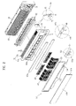
- FIG. 2 illustrates a bird's-eye view of a disassembled indoor unit of an air conditioner according to the present invention
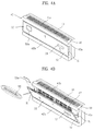
- FIG. 3A and FIG. 3B illustrate cross-sectional views of an indoor unit of an air conditioner according to the present invention.
- Air conditioners are divided in general into a one-body type air conditioner having all components built in one unit and a separate type air conditioner having all components built in outdoor and indoor units.
- the present invention explains embodiments applied to the separate type air conditioner.
- an outdoor unit of an air conditioner according to the present invention has the same constitution of a general outdoor unit, for which explanation is skipped in the following description.
- an indoor unit of an air conditioner includes a main chassis 10, a heat exchanger 20 installed inside the main chassis 10, a blow fan 30 installed inside the min chassis 10, a front panel 40 installed in front of the main chassis 20, and an intake panel 50 installed at a front face of the front panel 40.
- the main chassis 10 is basically constituted so as to receive various components for the operation of the indoor unit.
- a blow outlet 14 is formed at a bottom of the main chassis 10 so as to blow an air having heat-exchanged on the indoor unit, and a blow assembly 60 is loaded on the blow outlet 14.
- the blow assembly 60 includes a vane, a louver, or the like so as to adjust a blow direction of the heat-exchanged air right and left as well as upward and downward.
- the blow outlet 14 and blow assembly 60 as shown in FIG. 3A and FIG.
- the blow outlet 14 is formed at the bottom face of the indoor unit instead of the front face, thereby improving a front exterior of the indoor unit.
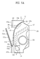
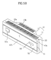
- the main chassis 10, as shown in FIG. 5A and 5B, can have a doubled structure including a front part 11 and a rear part 12 installed at a wall face of a room.
- the front and rear parts are interconnected, and the heat exchanger 20, blow fan 30 and the like are installed in a space between the front and rear parts 11 and 12.
- the front part 11 is rectangular in figure, and the blow outlet 14 is formed at a bottom of the front part 11.
- the front part 11 can be built in one body of the front panel 40.
- the rear part 12 protrudes from a back face of the front part 11, and has upper/lower and right/left widths which are narrower than those of the front part 11. Hence, if the rear part 12 is hanged on the wall of the room, a user mainly sees the front part 11. Thus, it is recognized that an exterior of the indoor unit looks slim visually. Specifically, if a concave recess is formed at the room wall so as to correspond to the rear part 12, the indoor unit occupies a less space since the front part 11 protrudes out of the wall face of the room only. Moreover, the rear part 12 can be a member separable from the front part 11, or built in one body of the front part 12.
- extra intake inlets 13a and 13b can be formed at upper faces of the front and rear parts 11 and 12 so as to improve an intake efficiency.
- the intake inlets 13a and 13b may further include an intake grill.
- the heat exchanger 20 exchanges heat with a room air sucked into the indoor unit through an operational fluid such as a refrigerant flowing inside the heat exchanger 20.
- the blow fan 30 is generally located in a rear of the heat exchanger 20, and revolves by a motor 31 so as to circulate the room air forcibly through the indoor unit. Namely, the blow fan 30 sucks the room air inside the indoor unit so that the heat exchanger 20 exchanges heat with the room air and discharges the heat-exchanged air outside the indoor unit.
- the heat exchanger 20, as shown in FIG. 3A, FIG. 3B, and FIG. 5A has a properly bent shape so as to carry out the heat exchange on the entire room air sucked in through the intake inlets formed at the upper side of the indoor unit as well as at the front part of the indoor unit.
- the front panel 40 basically seals a front face of the main chassis 10 so as to provide a space in which various components such as the heat exchanger 20, blow fan 30, and the like are installed together with the main chassis 10.
- a main intake inlet 41a is formed at a front face of the front panel 40 so as to make the room air sucked inside the heat exchanger 20.
- an auxiliary intake inlet 141b can be formed at an upper side of the front panel 40 instead of the upper intake inlets 13a and 13b of the main chassis 10.
- a recess portion 40a is formed at a front face of the front panel 40 for the intake panel 50 so as to be recessed inside, and decoration panels 42a and 42b are installed at upper and lower sides of the recess portion 40a.
- the decoration panels include various colors and patterns so as to decorate the front face of the indoor unit, and make the front face of the indoor unit flat together with the intake panel 50 so as to improve an exterior of the air conditioner.
- the decoration panels 42a and 42b can be built in one body of the front panel 40.
- an electrostatic precipitator 45 and an air filter 47 are installed at the main intake inlet 41a so as to purify the intake air.
- the front panel 40 if necessary for design, can be built in one body of the main chassis 10.
- the intake panel 50 is made of a plane member enabling to cover the main intake inlet 41a entirely so as to open/close the main intake inlet 41a selectively.
- the intake panel 50 is basically installed at the front panel 40 so as to move revolvably.
- a lower end portion of the intake panel 50 is hinge-connected to a lower front face of the front panel 40.
- the intake panel 50 revolves centering around the lower end portion so as to open the main intake inlet 41a on operating the air conditioner or close the main intake inlet 41a on stopping the operation of the air conditioner.
- the intake panel 50 is made of a thin plane member so as to make the indoor unit compact overall.
- the planarized front face of the intake panels improves the exterior of the indoor unit.
- the intake panel 50 closes the main intake inlet 41a completely when the air conditioner stops operating, thereby enabling to prevent penetration of the particles through the main intake inlet 41a.
- the intake panel 50 and front panel 40 are connected to each other through hinge, whereby the present invention enables to close/open the main intake inlet 41a with such a relatively simple structure.
- the intake panel 50 may include a main plate 51 loaded on the front panel 40 and an auxiliary plate 52 attached to a front face of the main plate 51.
- a cavity portion is preferably formed at the main plate 51 for the auxiliary plate 52.
- the auxiliary plate 52 can be made of a double-structured or single-structured member.
- the auxiliary plate 52 as the double-structured member may include a first layer 52a and a second layer 52b located at a rear side of the first layer 52a.
- the first layer 52a is made of tempered glass or transparent plastics so as to transmit light.
- the second layer 52b reflects the lights transmitted by the first layer 52a and is made of a metal film or dielectric multi-layers.
- the metal film is an Ag or Al layer coated on a grinded rear face of the first layer 52a, and the dielectric multi-layers are deposited on the rear face of the first layer 52a.
- auxiliary plate 52 In such an auxiliary plate 52, light incident on the front face of the indoor unit permeates the first layer 52a so as to be reflected on the second layer 52b, whereby the intake panel 50 works as a mirror. Moreover, the second layer 52 can be colored by a predetermined color, and such a color appears through the transparent first layer 52a. Meanwhile, the auxiliary plate 52 as the single-structured member can include various forms of patterns and colors. Specifically, the pattern and color of wood grain gives elegance to the indoor unit. Hence, the exterior of the air conditioner can be improved better by the auxiliary plate 52.
- An insertion slot 55 can be formed at the intake panel 50 so that prints 55a such as a picture and the like can be inserted in the slot.
- a display unit 56 displaying an operational status of the air conditioner can be installed at the intake panel 50 as well.
- the insertion slot 55 and display unit 56 improve the exterior of the air conditioner as well as give the intake panel 50 more various usages.
- the intake panel 50 when the intake panel 50 becomes fully open, the main intake inlet 41a is exposed entirely so as to degrade the exterior of the indoor unit.
- the intake panel 50 preferably revolves to a predetermined angle from the front panel 40. Namely, when the air conditioner operates, the intake panel 50 maintains a uniform tilt angle for the front panel 40.
- Such a tilted intake panel 50 as shown in FIG. 3B, is located between the main intake inlet 41a and blow outlet 14. Hence, the intake and blow flows through the intake inlet 1a and blow outlet 14 are substantially separated from each other as well as fail to interfere with each other.
- the tilted intake panel 50 enables to cover the open main intake inlet 41a so as not to be seen. Moreover, the user enables to see the display unit 56 and the like installed at the intake panel 50 more vividly.
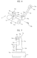
- the intake panel 50 further includes a driving means 70 supporting the intake panel 50 and simultaneously restricting revolution of the intake panel 50.
- Various mechanisms can be used as the driving means 70, and a link mechanism is applied to an embodiment of the present invention.
- a link driving means 70 permits a revolution of the intake panel as long as the limited link length.
- the link driving means 70 supports(restricts) the intake panel 50 so as not to revolve any more.
- the driving means 70 includes a first link 71 connected to the front panel 40 and a second link 72 connecting the first link 71 to the intake panel 50.
- the first link 71 includes a first end portion 71a connected to the front panel 40 revolvably and a second end portion 71b connected to the second link 72 reevolvably so as to confront the first end portion 71a.
- the second link 72 includes a first end portion 72a connected to the second end portion 71b of the first link 71 and a second end portion 72b connected to the intake panel 50 revolvably.
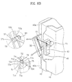
- a connecting unit of the first and second links 71 and 72 as shown in FIG. 6, Fig. 7, and FIG.
- the hinge pin 72 is pulled out of or inserted in the hinge hole 71d, whereby the first and second links 71 and 72 can be disassembled from each other with ease.
- the simply structured connecting unit enables the intake panel 50 to be repaired or replaced easily.
- the hinge hole and pin can be formed at the second and first links 72 and 71, respectively.
- the other connecting unit of the second link 71 and intake panel 50 as shown in FIG.
- the intake panel 50 and second link 72 can be easily disassembled by removing the hinge pin 58 so as to enable their easy repair and replacement.
- the driving means 70 further includes a motor 73 giving a driving force to the first and second links 71 and 72.
- a shaft of the motor 73 is inserted in a hole 71c of the first end portion 71a so that the motor 73 is connected to the first link to be inter-driven with the first link.
- the motor 73 is preferably a step motor so as to control revolution of the first link 71 step by step.
- the revolution and tilt angle of the intake panel 50 are adjusted to change an interval between the intake panel 50 and main intake inlet 41a, whereby intake airflow through the main intake inlet 41a is adjusted.
- the motor 73 is installed, a space between the intake panel 50 and front panel 40 is limited.
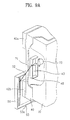
- the motor 73 is preferably installed at the rear face of the front panel 40 and the first link 71 is connected to the motor 73 through an opening 43 formed at the front panel 40.
- Such an installment structure prevents the motor 73 from being exposed when the main intake inlet 41a becomes open, thereby improving the exterior or appearance of the air conditioner.
- the opening 43 extends long upper to lower side, whereby the first and second links 71 and 72 can move smoothly. Yet, a size of the opening 43 increases so that a finger or other member can be inserted therein.
- the front panel 40 further includes a partition 48 around the opening 43.
- the partition 48 as shown in FIG. 8A and FIG. 8B, extends from a circumference of the opening 43 toward a rear side of the front panel 40.
- the partition 48 may extend from the circumference of the opening 43 in a direction vertical to the front face of the front panel 50.
- the partition 43 is formed to be inclined inward the opening 43 so as to reduce the size of the opening 43. Hence, it is prevented that the partition 48 approaches the components built in the indoor unit, whereby the user fails to receive an electric shock due to a contact between finger/external member and the component. Besides, malfunction of the components is prevented.
- the driving unit preferably further includes auxiliary connecting members formed at the connecting unit of the first and second links 71 and 72.
- auxiliary connecting members formed at the connecting unit of the first and second links 71 and 72.
- one of the auxiliary connecting members is a guide 74 formed at the second link 72.
- the guide 74 includes a horizontal member 74a extending from the first end portion 72a of the second link 72 along the second end portion 71b of the first link 71 and a vertical member 74b extending from the horizontal member 74a so as to cover a side face of the second end portion 71b.
- the guide 74 surrounds partially the second end portion 71b overall so as to prevent the second end portion 71b from deviating from the first end portion 72a of the second link 72.
- the guide 74 may be formed at the second end portion 71b of the first link 71 with the same shape.
- the auxiliary connecting member as shown in the drawing, may include a boss 75a formed near the second end portion 71b of the first link 71 and a coupling member 75b coupled with the boss 75a. As shown in detail in FIG. 7, the coupling member 75b is coupled with the boss 75a so as to gear into or contact with the first end portion 72a of the second link 72.
- the first end portion 72a is not separated from the second end portion 71b in a rotational shaft direction during operation.
- the boss 75a as is the case with the guide 74, can be formed near the first end portion 72a of the second link 72 instead of the second end portion 71b.
- the driving means 70 may further include a stopper 76 formed at the connecting unit of the first and second links 71 and 72.
- the connecting unit of the first and second links 71 and 72 allows the first and second links 71 and 72 to revolve freely, whereby the first and second links 71 and 72 revolve relatively only but the intake panel 50 may revolve no more. This phenomenon may occur possibly if a little external force is applied to the intake panel 50 during revolution.
- the stopper 74 protrudes from the second end portion 71b of the first link 71, as shown in FIG. 8B, whereby the second link 72 is caught on the stopper 74 during revolution so as to restrict the relative revolution of the second link 72 for the first link 71.
- the stopper 76 substantially maintains the angle between the first and second links 71 and 72 so as to be smaller than 180°. Therefore, the stopper 76 secures the stable revolution of the intake panel 50.
- the intake panel 50 is preferably detachable from the front panel 40.
- a loading unit of the intake and front panels 50 and 40 as shown in FIG. 2, FIG. 3A, FIG. 3B, and FIG. 5A, includes a hinge bar 44b formed at a lower part of the front panel 50 and a hinge ring 53 protruding at a lower end of the intake panel 50.
- the hinge bar 44b is installed in a groove having a predetermined size for smooth revolution of the hinge ring 53.
- the hinge ring 53 has a partially open shape 53a so as to be detachable from the hinge bar 44b.
- the intake panel 50 as shown in FIG. 9A and FIG. 9B, is easily separated from the front panel 40 so as to expose the main intake inlet 41a entirely.
- the air filter 47 is separated so as to be cleaned.
- the separated intake panel 50 is hung on the front panel 40 by the driving means, i.e. the first and second links 71 and 72, thereby the intake panel 50 can be reloaded with ease.
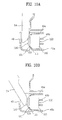
- the intake panel 50 further includes a power control unit cutting off a power of the inner component when the intake panel 50 is disassembled.
- the power control unit as shown in FIG. 2 and FIGs. 10A to 10C, includes a protrusion 54 formed at a lower end of the intake panel 50 and a power switch 100 fixed inside the front panel 40 through a predetermined fixing member.
- the protrusion 46 when the intake panel 50 is loaded on the front panel 40, is inserted in a penetrating hole 46 formed at the front panel 40 so as to reach an lower inside of the front panel 40.
- the switch 100 is a kind of relay switch connected between the inner components and power supply, and includes a body 110 and a terminal 120 connected to the body 110 and having elasticity. Specifically, one end of the terminal 120 is connected to the body 110, and the other end comes into contact with the body 110 when being pressurized. Electrical contact points 111 and 121 are installed at the body 110 and the other end of the terminal 120, respectively. When the other end of the terminal 120 is contacted with the body 110, the contact points 111 and 121 are connected to each other.
- the switch 100 is fixed stably by a hook 49a formed inside the front panel 40 adjacent to the penetrating hole 46 and ribs 49b located in rear of the switch.
- the hook 49a provides a recessed part in which the switch is inserted, and the ribs 49b support the switch 100 pressurized by the protrusion 54 so as not to be pushed.
- the protrusion 54 when the intake panel 50 is loaded, the protrusion 54, as shown in FIG. 10A, pressurizes the terminal 120. As the other end of the terminal 120 is contacted with the body 110, the contact points 111 and 121 are connected to each other so as to supply the inner components with power. Since the protrusion 54 maintains to be contacted with the terminal 120 while the intake panel 50 revolves, as shown in FIG. 10B, the supply of the power is kept on. Meanwhile, if the intake panel 50 is detached, the protrusion 54, as shown in FIG. 10C, is separated from the penetrating hole 46 so as to release the terminal 120. Hence, the terminal 120 restored by its own elasticity to separate the contact points 111 and 121 from each other so as to cut off the power supply to the inner components.
- the blow outlet 14 is formed at the bottom of the indoor unit for improving the exterior and cooling a lower area right under the indoor unit. Yet, such a blow outlet 14 is not suitable for blowing a chill air into the entire room evenly.
- the indoor unit according to the present invention further includes blow means 80 and 90 inserted inside or drawn out from the main chassis 10 so as to blow the heat-exchanged air into the room.
- the blow means 80 is drawn in or out along the blow outlet 14 upward and downward so as to open/close the blow outlet 14 selectively.
- a blow housing 81 is installed inside the main chassis 10 so as to move upward and downward along the blow outlet 14.
- the blow housing 81 is drawn outside in part through the blow outlet 14 in accordance with a degree of the descent.
- an auxiliary intake inlet 81a through which the heat-exchanged air is sucked in and an auxiliary blow outlet 81b connected to the room are formed at the blow housing 81.
- the blow housing 81 has a rectangular shape of which right/left width is longer than a front/rear width, and the auxiliary blow outlets 81a and 81b are formed at an upper face and a lower front face of the blow housing, respectively.
- a member controlling a blow direction of an air is preferably installed inside the blow housing 81.
- a vane 83 controlling the blow direction of the air upward and downward and a louver 84 controlling the blow direction of the air right and left are installed inside the blow housing 81.
- an auxiliary intake grill 82 is formed at the auxiliary intake inlet 81a so as to guide a smooth airflow.
- the blow housing 81 can be lifted by a direct user's operation. Instead, it is preferable that the blow housing 81 is lifted automatically in accordance with the operation of the air conditioner. For this, a driving means for elevating the blow housing 81 automatically is further installed.
- the driving means includes a motor 85 receiving a power to generate a turning force, a pinion 86 connected to a driving shaft of the motor 85, and a rack 87 installed at a rear wall of the blow housing 81 in upper/lower direction so as to gear into the pinion 86.
- the driving means is installed in rear of the blow housing 81. Instead, it is preferable that the driving means is installed at a lateral side of the blow housing 81.
- a stopper 88 is installed at a front wall of the blow housing 81. Once the blow housing 81 is moved downward with a predetermined distance, the stopper 88 is caught on the bottom of the main chassis 10 so as to fail to move downward no more.
- a second embodiment 90 of the blow means revolves to move inside the blow inlet 14 so as to close/open the blow outlet 14 selectively.
- a blow housing 91 having a revolution center near the blow outlet 14 is installed at the bottom face of the main chassis 10 so as to revolve to move to be drawn outside through the blow outlet 14.
- an auxiliary intake inlet 91a through which the heat-exchanged air is sucked in and an auxiliary blow outlet 91b connected to the room are formed at the blow housing 91.
- the blow housing 91 has a fan-shape cross-section, and the auxiliary intake inlet 91a and auxiliary blow outlet 91b are formed at an upper face and a lower circumferential face of the blow housing 91, respectively.
- a rotating shaft 96 of the blow housing 91 is formed near a vertex of the fan-shape cross-section. If the blow housing 91 revolves clockwise centering around the rotating shaft 96 so as to be inserted inside the main chassis 10 completely, the blow outlet 14 is closed by the blow housing 91. On the contrary, if the blow housing 91 revolves counterclockwise so as to draw out the auxiliary blow outlet 91b outside, the blow outlet 14 becomes open. Namely, the inner space of the main chassis 10 leads to the room through the auxiliary intake inlet 91a and auxiliary blow outlet 91b.
- a vane 93 adjusting a blow direction of the heat-exchanged air upward and downward and a louver 94 adjusting the blow direction right and left are installed inside the blow housing 91.
- an auxiliary intake grill 92 is further installed at the auxiliary intake inlet 91a so as to guide airflow more smoothly.
- a stopper 97 is installed at an upper circumferential face of the blow housing 91 so as to restrict a revolution angle of the blow housing 91. Once the blow housing 91 revolves with a predetermined degree, the stopper 97 is caught on a lower face of the main chassis 10 so that the blow housing is unable to revolve any more.
- the blow housing 91 revolves to move automatically in accordance with the operation of the air conditioner as well.
- a driving means revolving the blow housing 91 automatically is further installed at the blow means 90.
- the driving means is a motor 95 generating a turning force by receiving a power, and a driving shaft of the motor 95 is directly connected to the rotating shaft 96 of the blow housing 91.
- the first link 71 starts to revolve by the motor 73 toward a front side of the indoor unit as well as the second link 72 follows the first link 71 to revolve.
- the stopper 76 is formed at the first link 71
- the stopper 76 is caught on the second link 72 so that the second link 72 is restricted by the first link 71.
- the first and second links 71 and 72 then push the second link 72 toward the intake panel 72 without reciprocal revolution between the first and second links 71 and 72, thereby securing the stable revolution of the intake panel 50.
- the auxiliary connecting members 74 and 75 maintain the connected state of the first and second links 71 and 72 for the revolution of the intake panel.
- the intake panel 62 keeps on revolving continuously centering around its lower end and is arranged to incline to the front panel 40 with a predetermined angle so as to open the main intake inlet 41a of the front panel 40.
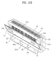
- the blow housing 81 descends by reciprocal reaction between the pinion 86 and rack 87 when a power is applied to the motor 85, which is shown in FIG. 11B. Hence, the descent of the blow housing 81 makes the blow outlet 14 open. Namely, the inner space of the main chassis 10 leads to the room through the auxiliary intake inlet 81a and auxiliary blow outlet 81b.
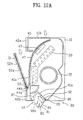
- a power is applied to the motor 95 so as to revolve the blow housing 91 the moment the intake panel 50 revolves, which is shown in FIG. 12B.
- the revolution of the blow housing 91 makes the blow outlet 14 open.
- the blow fan 30 starts to revolve by the fan motor 31 so that the room air is sucked inside the indoor unit through the main and auxiliary intake inlets 41a and 41b.
- the intake panel 50 opens the main intake inlet 41a overall so as to suck in air more than the blow grill of the related art do.
- the tilt angle of the intake panel 50 is adjusted so as to control the interval between the intake panel 50 and front panel. Such an interval control enables to control the air blow amount as well as the air intake amount.
- the intake air passes the air filter 47 so as to remove large particles, and then passes the electrostatic precipitator 45 so as to precipitate minute particles such as dust and the like. Subsequently, the air passes the heat exchanger 20 for heat exchange with the refrigerant so as to be cooled, and then moves toward the blow outlet 14.
- the cooled air flows inside the blow housing 81 or 91 through the auxiliary intake inlet 81a or 81b.
- the cooled air is then guided by the vane 83 or 93 and louver 84 or 94 so as to be blown into the room through the auxiliary blow outlet 81b or 91b.
- the intake panel 50 is tilted between the main intake inlet 41a and auxiliary blow outlet 81b or 91b so as to work as the partition dividing the space therebetween.
- the interference between the intake and blow is excluded so as to prevent the blow air fails to be sucked in through the main intake inlet 41a again.
- the blow housing 81 or 91 is drawn out from the main chassis 10 downwardly, the cooled air can be blown into the entire area of the room evenly as well as the area under the indoor unit.
- the fan motor 31, blow fan 31, and heat exchanger 20 stop operating. Thereafter, the intake panel 50 and blow housing 81 or 91, as shown in FIG. 3A and FIG. 3B, operate in order reverse to the foregoing explanation so as to close the main intake inlet 41a and blow outlet 14.
- the hinge ring 53 at the lower end of the intake panel 50 is separated from the hinge bar 44b by its opening portion 53a.
- the intake panel 50 is separated from the front panel 50 with ease.
- the main intake inlet 41a is fully opened.
- the main intake inlet 41a is open, the second link 71 is caught on the stopper 76 so as to revolve no more than 180° for the first link 71.
- the intake panel 50 is hung so as to be left apart with a predetermined interval from the lower portion of the front panel 40.
- the intake panel 50 is free from causing damage on the lower portion of the front panel 40 when being attached to or detached from.
- the protrusion 54 is detached from the penetrating hole 46 so that the contact points 111 and 121 are separated from each other.
- the power supply becomes cut off to the inner components, whereby the user is protected from an electric shock.
- the user separates the intake panel 50, thereby enabling to disassemble conveniently the inner components such as air filter 47, electrostatic precipitator 45, and the like through the fully opened main intake inlet 41a for cleaning and replacement. Moreover, since the separated intake panel 50 is hung on the indoor unit, the user enables to reload the intake panel 50 conveniently after loading the inner components 45 and 47.
- a flat panel type intake panel is used instead of the blow grill of the related art, thereby providing a compact size of the indoor unit as well as improving the exterior. And, the intake panel closes the intake inlet on stopping operation, thereby preventing particles from flowing inside the air conditioner.
- the intake panel inclines to the front panel on operation, the intake inlet fails to be exposed to a user so as to improve the exterior of the indoor unit. And, the tilted front panel excludes the interference between the intake and blow airflows, thereby improving heat exchange efficiency. Besides, the tilt angle of the intake panel is adjusted so as to control intake and blow air amounts.
- the intake panel is detachable, it is easy to manage the inner components such as the air filter, electrostatic precipitator, and the like. Since the intake panel is dangled from the indoor unit, the user enables to reload the intake panel conveniently.
- the blow means are drawn out from the bottom of the indoor unit, thereby enabling to blow the chill air to all over the room evenly as well as the area right under the indoor unit.
- the invention also provides an air conditioner as set out in the following numbered paragraphs.
Applications Claiming Priority (6)
| Application Number | Priority Date | Filing Date | Title |
|---|---|---|---|
| KR10-2001-0034839A KR100420315B1 (ko) | 2001-06-19 | 2001-06-19 | 공기조화기의 실내기 |
| KR10-2002-0021625A KR100457563B1 (ko) | 2002-04-19 | 2002-04-19 | 공기조화기 |
| KR10-2002-0021626A KR100437049B1 (ko) | 2002-04-19 | 2002-04-19 | 공기조화기의 흡입패널 개폐구조 |
| KR1020020021627A KR20030083191A (ko) | 2002-04-19 | 2002-04-19 | 공기조화기의 프론트 패널 개폐 구조 |
| KR10-2002-0021628A KR100471436B1 (ko) | 2002-04-19 | 2002-04-19 | 공기조화기의 안전형 전면패널 구조 |
| EP02254266A EP1271065B1 (de) | 2001-06-19 | 2002-06-19 | Klimaanlage |
Related Parent Applications (1)
| Application Number | Title | Priority Date | Filing Date |
|---|---|---|---|
| EP02254266A Division EP1271065B1 (de) | 2001-06-19 | 2002-06-19 | Klimaanlage |
Publications (2)
| Publication Number | Publication Date |
|---|---|
| EP1793178A2 true EP1793178A2 (de) | 2007-06-06 |
| EP1793178A3 EP1793178A3 (de) | 2007-06-27 |
Family
ID=27532369
Family Applications (7)
| Application Number | Title | Priority Date | Filing Date |
|---|---|---|---|
| EP05078041A Expired - Lifetime EP1657502B1 (de) | 2001-06-19 | 2002-06-19 | Klimaanlage |
| EP06024669A Withdrawn EP1793177A3 (de) | 2001-06-19 | 2002-06-19 | Klimaanlage |
| EP05078040A Expired - Lifetime EP1657501B1 (de) | 2001-06-19 | 2002-06-19 | Klimaanlage |
| EP02254266A Expired - Lifetime EP1271065B1 (de) | 2001-06-19 | 2002-06-19 | Klimaanlage |
| EP05078039A Expired - Lifetime EP1657500B1 (de) | 2001-06-19 | 2002-06-19 | Klimaanlage |
| EP06024670A Withdrawn EP1793178A3 (de) | 2001-06-19 | 2002-06-19 | Klimaanlage |
| EP05078038A Expired - Lifetime EP1657499B1 (de) | 2001-06-19 | 2002-06-19 | Klimaanlage |
Family Applications Before (5)
| Application Number | Title | Priority Date | Filing Date |
|---|---|---|---|
| EP05078041A Expired - Lifetime EP1657502B1 (de) | 2001-06-19 | 2002-06-19 | Klimaanlage |
| EP06024669A Withdrawn EP1793177A3 (de) | 2001-06-19 | 2002-06-19 | Klimaanlage |
| EP05078040A Expired - Lifetime EP1657501B1 (de) | 2001-06-19 | 2002-06-19 | Klimaanlage |
| EP02254266A Expired - Lifetime EP1271065B1 (de) | 2001-06-19 | 2002-06-19 | Klimaanlage |
| EP05078039A Expired - Lifetime EP1657500B1 (de) | 2001-06-19 | 2002-06-19 | Klimaanlage |
Family Applications After (1)
| Application Number | Title | Priority Date | Filing Date |
|---|---|---|---|
| EP05078038A Expired - Lifetime EP1657499B1 (de) | 2001-06-19 | 2002-06-19 | Klimaanlage |
Country Status (12)
| Country | Link |
|---|---|
| US (1) | US6725684B2 (de) |
| EP (7) | EP1657502B1 (de) |
| JP (1) | JP3735592B2 (de) |
| CN (3) | CN1247941C (de) |
| AT (5) | ATE412144T1 (de) |
| AU (1) | AU2002314572A1 (de) |
| DE (5) | DE60229569D1 (de) |
| ES (5) | ES2277986T3 (de) |
| MY (1) | MY136575A (de) |
| PT (1) | PT1271065E (de) |
| TW (1) | TW593938B (de) |
| WO (1) | WO2002103248A2 (de) |
Families Citing this family (107)
| Publication number | Priority date | Publication date | Assignee | Title |
|---|---|---|---|---|
| JP4279564B2 (ja) * | 2002-11-11 | 2009-06-17 | 三星電子株式会社 | 空気調和機 |
| AU2003203151A1 (en) * | 2003-02-07 | 2004-08-30 | A/S Ribe Jernindustri | Ventilating aggregate , units, system and methode including units that are easily connectable to other units and safety switch |
| SG156529A1 (en) * | 2003-03-26 | 2009-11-26 | Daikin Ind Ltd | Indoor unit of an air conditioner |
| KR100937417B1 (ko) | 2003-06-20 | 2010-01-18 | 엘지전자 주식회사 | 드럼세탁기용 세제박스 |
| KR100541471B1 (ko) | 2003-08-29 | 2006-01-10 | 엘지전자 주식회사 | 에어컨 실내기 |
| JP3641721B2 (ja) | 2003-08-29 | 2005-04-27 | ダイキン工業株式会社 | 空気調和機の室内機および空気調和機の室内機の製造方法 |
| CN100404963C (zh) * | 2003-09-01 | 2008-07-23 | 大金工业株式会社 | 空调机的室内机及其制造方法 |
| JP3642064B2 (ja) * | 2003-09-01 | 2005-04-27 | ダイキン工業株式会社 | 空気調和機の室内機およびその製造方法 |
| JP3641724B2 (ja) * | 2003-09-30 | 2005-04-27 | ダイキン工業株式会社 | 空気調和機の室内機 |
| AU2004278589B2 (en) * | 2003-09-30 | 2007-10-11 | Daikin Industries, Ltd. | Indoor unit of air conditioner |
| JP3641723B2 (ja) * | 2003-09-30 | 2005-04-27 | ダイキン工業株式会社 | 空気調和機の室内機および空気調和機の室内機の組立方法 |
| WO2005040690A1 (en) * | 2003-10-24 | 2005-05-06 | Lg Electronics Ltd. | Indoor unit in air conditioner |
| KR100626443B1 (ko) * | 2003-11-24 | 2006-09-20 | 엘지전자 주식회사 | 공기조화기의 실내기 |
| KR100626444B1 (ko) * | 2003-11-24 | 2006-09-20 | 엘지전자 주식회사 | 공기조화기의 실내기 |
| WO2005103574A1 (en) * | 2004-04-20 | 2005-11-03 | Lg Electronics Inc. | Air conditioner |
| US20060005559A1 (en) * | 2004-06-14 | 2006-01-12 | Lg Electronics Inc. | Air conditioner |
| US7350370B2 (en) * | 2004-06-15 | 2008-04-01 | Lg Electronics Inc. | Air conditioner |
| CN100441962C (zh) * | 2004-06-21 | 2008-12-10 | 乐金电子(天津)电器有限公司 | 空调器的室内机 |
| WO2006001563A2 (en) | 2004-06-29 | 2006-01-05 | Lg Electronics Inc. | Indoor device of separable air conditioner |
| KR100624793B1 (ko) * | 2004-06-29 | 2006-09-20 | 엘지전자 주식회사 | 분리형 공기조화기의 실내기 |
| ATE527503T1 (de) | 2004-07-14 | 2011-10-15 | Daikin Ind Ltd | Innenraumeinheit einer klimaanlage |
| WO2006006623A1 (ja) * | 2004-07-14 | 2006-01-19 | Daikin Industries, Ltd. | 空気調和機の室内機 |
| EP1787064A2 (de) * | 2004-07-27 | 2007-05-23 | LG Electronics Inc. | Klimaanlage |
| CN1318807C (zh) * | 2004-08-09 | 2007-05-30 | 广东科龙电器股份有限公司 | 空调室内机 |
| EP1778385B1 (de) * | 2004-08-16 | 2009-08-05 | LG Electronics, Inc. | Filtereinheit einer klimaanlage |
| US7565814B2 (en) | 2004-09-09 | 2009-07-28 | Daikin Industries, Ltd. | Indoor unit of air conditioner |
| JP4614734B2 (ja) * | 2004-10-28 | 2011-01-19 | シャープ株式会社 | 空気調和機 |
| JP3806881B2 (ja) | 2004-11-08 | 2006-08-09 | ダイキン工業株式会社 | 空気調和装置の室内ユニット |
| ES2226595B1 (es) * | 2004-12-10 | 2006-06-01 | Bsh Electrodomesticos España, S.A. | Equipo de aire acondicionado. |
| JP4252530B2 (ja) * | 2004-12-13 | 2009-04-08 | ダイキン工業株式会社 | 空気調和機のドレン水静菌構造 |
| CN1322270C (zh) * | 2004-12-21 | 2007-06-20 | 广东科龙电器股份有限公司 | 一种空调器室内机 |
| WO2006080776A1 (en) * | 2005-01-26 | 2006-08-03 | Lg Electronics Inc. | Air conditioner |
| WO2006075850A1 (en) * | 2005-01-11 | 2006-07-20 | Lg Electronics Inc. | Air conditioner |
| KR100691894B1 (ko) * | 2005-02-01 | 2007-03-09 | 엘지전자 주식회사 | 공기 조화기 |
| BRPI0518502A2 (pt) * | 2005-02-01 | 2008-11-25 | Lg Electronics Inc | aparelho de ar condicionado |
| KR20060093985A (ko) * | 2005-02-23 | 2006-08-28 | 엘지전자 주식회사 | 공기 조화기 |
| KR101126958B1 (ko) * | 2005-02-23 | 2012-03-26 | 엘지전자 주식회사 | 공기 조화기 |
| JP2006234280A (ja) * | 2005-02-24 | 2006-09-07 | Sharp Corp | 空気調和機 |
| KR101054623B1 (ko) * | 2005-03-09 | 2011-08-04 | 엘지전자 주식회사 | 공기 조화기 |
| KR20060099004A (ko) * | 2005-03-10 | 2006-09-19 | 엘지전자 주식회사 | 공기 조화기 |
| KR20070000673A (ko) * | 2005-06-28 | 2007-01-03 | 삼성전자주식회사 | 도어힌지장치 및 이를 갖춘 전자기기 |
| CN101268317B (zh) * | 2005-07-29 | 2012-08-22 | 开利公司 | 用于蒸发器单元的进风栅和过滤器组件 |
| WO2007049870A2 (en) | 2005-10-26 | 2007-05-03 | Lg Electronics, Inc. | Indoor unit for air conditioner |
| KR100724389B1 (ko) * | 2005-12-29 | 2007-06-04 | 엘지전자 주식회사 | 토출구도어를 구비한 공기조화기의 실외기 |
| KR101257505B1 (ko) | 2006-01-16 | 2013-04-23 | 엘지전자 주식회사 | 공기조화기의 실내기 |
| US8505327B2 (en) | 2006-01-16 | 2013-08-13 | Lg Electronics Inc. | Indoor unit for air conditioner |
| WO2007086643A2 (en) * | 2006-01-24 | 2007-08-02 | Lg Electronics Inc. | Indoor unit of air conditioner |
| KR101233198B1 (ko) | 2006-02-07 | 2013-02-15 | 엘지전자 주식회사 | 공기조화기의 실내기 |
| KR101203569B1 (ko) * | 2006-02-07 | 2012-11-21 | 엘지전자 주식회사 | 공기조화기의 실내기 |
| AU2006337754B2 (en) | 2006-02-07 | 2010-02-18 | Lg Electronics Inc. | Indoor unit of air conditioner |
| WO2007091768A2 (en) * | 2006-02-07 | 2007-08-16 | Lg Electronics Inc. | Indoor unit of air conditioner |
| WO2007091766A2 (en) | 2006-02-07 | 2007-08-16 | Lg Electronics Inc. | Indoor unit of air conditioner |
| WO2007091767A2 (en) * | 2006-02-09 | 2007-08-16 | Lg Electronics Inc. | Indoor unit of air conditioner |
| US7857884B2 (en) * | 2006-06-30 | 2010-12-28 | Oreck Holdings, Llc | Air cleaner including an improved airflow path |
| KR20080006757A (ko) * | 2006-07-13 | 2008-01-17 | 엘지전자 주식회사 | 평판표시유닛이 설치된 공기조화기 |
| KR100769914B1 (ko) * | 2007-01-29 | 2007-10-24 | 엘지전자 주식회사 | 공기조화기의 실내기 |
| EP1950501A1 (de) * | 2007-01-29 | 2008-07-30 | Lg Electronics Inc. | Klimaanlage |
| KR100769913B1 (ko) * | 2007-01-29 | 2007-10-24 | 엘지전자 주식회사 | 공기조화기의 실내기 |
| US8303677B2 (en) * | 2007-02-09 | 2012-11-06 | Daikin Industries, Ltd. | Indoor unit of air conditioner |
| CN101329085B (zh) * | 2007-06-18 | 2011-04-06 | 珠海格力电器股份有限公司 | 一种可用于展示工艺品的空调室内机 |
| CN201069238Y (zh) * | 2007-07-25 | 2008-06-04 | 珠海格力电器股份有限公司 | 空调器室内机面板的支撑机构 |
| ES2392366T3 (es) * | 2007-08-28 | 2012-12-10 | Mitsubishi Electric Corporation | Acondicionador de aire |
| JP4537433B2 (ja) * | 2007-08-30 | 2010-09-01 | 三菱電機株式会社 | 空気調和機 |
| WO2009036535A2 (en) * | 2007-09-18 | 2009-03-26 | Carrier Corporation | Front panel for an air conditioning unit |
| KR20090042056A (ko) * | 2007-10-25 | 2009-04-29 | 삼성전자주식회사 | 공기조화기 |
| KR101428677B1 (ko) * | 2008-05-23 | 2014-09-23 | 엘지전자 주식회사 | 공기조화기 |
| JP4992874B2 (ja) * | 2008-09-12 | 2012-08-08 | 株式会社富士通ゼネラル | 空気調和機の装飾部品の取付構造 |
| EP2347187A4 (de) * | 2008-10-21 | 2017-08-23 | LG Electronics Inc. | Klimaanlage |
| JP5126599B2 (ja) * | 2008-10-29 | 2013-01-23 | 株式会社富士通ゼネラル | 空気調和機の室内ユニット |
| KR101632884B1 (ko) * | 2008-12-23 | 2016-06-23 | 엘지전자 주식회사 | 천장형 공기조화기 |
| KR101045380B1 (ko) * | 2008-12-23 | 2011-06-30 | 엘지전자 주식회사 | 천장형 공기조화기 |
| JP5158373B2 (ja) * | 2009-03-19 | 2013-03-06 | 株式会社富士通ゼネラル | 空気調和機 |
| JP5110095B2 (ja) | 2010-01-21 | 2012-12-26 | ダイキン工業株式会社 | 空調室内機のパネル |
| JP5388998B2 (ja) * | 2010-11-26 | 2014-01-15 | 三菱電機株式会社 | 空気調和機の室内機 |
| US8931762B2 (en) * | 2010-12-23 | 2015-01-13 | Lg Electronics Inc. | Air conditioner |
| CN202470348U (zh) * | 2012-02-29 | 2012-10-03 | 珠海格力电器股份有限公司 | 导风板驱动装置及使用该驱动装置的空调室内机 |
| JP5928301B2 (ja) * | 2012-10-31 | 2016-06-01 | 株式会社富士通ゼネラル | 空気調和機 |
| JP6136307B2 (ja) * | 2013-01-31 | 2017-05-31 | 株式会社富士通ゼネラル | 空気調和機 |
| KR102040800B1 (ko) * | 2013-04-11 | 2019-12-05 | 삼성전자주식회사 | 블레이드 체결구조 및 이를 갖는 공기조화기 |
| USD754830S1 (en) * | 2013-07-04 | 2016-04-26 | Gree Electric Appliances, Inc. Of Zhuhai | Air conditioner |
| KR101702169B1 (ko) | 2013-10-02 | 2017-02-02 | 엘지전자 주식회사 | 카세트형 공기조화기의 실내기 |
| KR101706812B1 (ko) | 2013-10-02 | 2017-02-14 | 엘지전자 주식회사 | 카세트형 공기조화기의 실내기 |
| KR20150041340A (ko) * | 2013-10-08 | 2015-04-16 | 엘지전자 주식회사 | 카세트형 공기조화기의 실내기 |
| KR20150043573A (ko) | 2013-10-11 | 2015-04-23 | 엘지전자 주식회사 | 공기조화기의 실내기 |
| JP5850032B2 (ja) * | 2013-11-26 | 2016-02-03 | ダイキン工業株式会社 | 室内機 |
| CN105765317B (zh) * | 2013-11-26 | 2019-05-10 | 大金工业株式会社 | 室内机 |
| KR101662377B1 (ko) | 2014-01-27 | 2016-10-04 | 엘지전자 주식회사 | 공기조화기의 실내기 |
| WO2016143010A1 (ja) * | 2015-03-06 | 2016-09-15 | 三菱電機株式会社 | 空気調和機 |
| KR101769822B1 (ko) | 2016-01-14 | 2017-08-21 | 엘지전자 주식회사 | 공기조화기 |
| CN107289510B (zh) * | 2016-04-06 | 2024-01-23 | 广东美的制冷设备有限公司 | 一种挂壁式空调器室内机 |
| CN108548221A (zh) * | 2016-08-31 | 2018-09-18 | 芜湖美智空调设备有限公司 | 空气处理装置 |
| CN106556064A (zh) * | 2016-10-21 | 2017-04-05 | 珠海格力电器股份有限公司 | 空调器 |
| JP2018091506A (ja) * | 2016-11-30 | 2018-06-14 | 三菱重工サーマルシステムズ株式会社 | 空気調和機の室内機、及び空気調和機の室内機の組立方法 |
| CN116817367A (zh) * | 2016-12-05 | 2023-09-29 | 奥克斯空调股份有限公司 | 一种挂机结构 |
| WO2018158940A1 (ja) * | 2017-03-03 | 2018-09-07 | 三菱電機株式会社 | 空気調和機の室内機 |
| JPWO2018163574A1 (ja) * | 2017-03-06 | 2019-12-26 | パナソニックIpマネジメント株式会社 | 空気調和機 |
| US10921019B2 (en) * | 2017-03-14 | 2021-02-16 | Mitsubishi Electric Corporation | Ceiling concealed air-conditioning apparatus |
| WO2018185882A1 (ja) * | 2017-04-05 | 2018-10-11 | 三菱電機株式会社 | 空気調和機の室内ユニット及び空気調和機 |
| CN107327928B (zh) * | 2017-07-25 | 2024-04-26 | 广东美的制冷设备有限公司 | 空调器室内机 |
| CN107388385B (zh) * | 2017-08-23 | 2023-12-12 | 广东美的制冷设备有限公司 | 空调室内机和空调器 |
| JP6680282B2 (ja) * | 2017-09-27 | 2020-04-15 | ダイキン工業株式会社 | 空調室内機 |
| CN108087978A (zh) * | 2018-01-04 | 2018-05-29 | 广东美的制冷设备有限公司 | 壁挂式空调室内机和空调器 |
| CN108253527A (zh) * | 2018-01-13 | 2018-07-06 | 广东美的制冷设备有限公司 | 微孔导风板、出风面板和空调柜机 |
| CN109185981A (zh) * | 2018-10-29 | 2019-01-11 | 奥克斯空调股份有限公司 | 一种空调器面板及空调器室内机 |
| CN213983977U (zh) * | 2020-11-16 | 2021-08-17 | 北京小米移动软件有限公司 | 空调导风板运动组件 |
| US20220373223A1 (en) * | 2021-05-24 | 2022-11-24 | Lg Electronics Inc | Air-processing apparatus |
| US20220373196A1 (en) * | 2021-05-24 | 2022-11-24 | Lg Electronics Inc. | Air-conditioning system |
Citations (5)
| Publication number | Priority date | Publication date | Assignee | Title |
|---|---|---|---|---|
| JPH03213921A (ja) * | 1990-01-18 | 1991-09-19 | Mitsubishi Electric Corp | 表示画面付空気調和装置 |
| JP2000039171A (ja) * | 1999-08-03 | 2000-02-08 | Hitachi Ltd | 空気調和機 |
| JP2000111082A (ja) * | 1998-09-30 | 2000-04-18 | Fujitsu General Ltd | 空気調和機 |
| JP2001041561A (ja) * | 1999-07-23 | 2001-02-16 | Daikin Ind Ltd | 空気調和機 |
| EP1087183A1 (de) * | 1998-06-08 | 2001-03-28 | Daikin Industries, Limited | Innenraumeinheit für eine klimaanlage |
Family Cites Families (28)
| Publication number | Priority date | Publication date | Assignee | Title |
|---|---|---|---|---|
| AU542354B2 (en) * | 1981-10-21 | 1985-02-21 | Mitsubishi Denki Kabushiki Kaisha | Ceiling mounted air conditioner |
| JPS58100823A (ja) * | 1981-12-11 | 1983-06-15 | Canon Inc | 表示装置 |
| JPH04145A (ja) * | 1990-04-13 | 1992-01-06 | Mitsubishi Electric Corp | 空気調和機 |
| JPH0420923U (de) * | 1990-06-13 | 1992-02-21 | ||
| JPH05187706A (ja) * | 1992-01-08 | 1993-07-27 | Toshiba Corp | 空気調和機の室内ユニット |
| JPH06174255A (ja) * | 1992-12-07 | 1994-06-24 | Matsushita Electric Ind Co Ltd | 空気調和機の吸入グリル開閉型室内ユニット |
| JPH0798129A (ja) * | 1993-09-30 | 1995-04-11 | Matsushita Seiko Co Ltd | 分離型空気調和機 |
| US5600963A (en) * | 1994-08-20 | 1997-02-11 | Samsung Electronics Co., Ltd. | Indoor unit of an air conditioner system |
| JP3005450B2 (ja) * | 1995-04-27 | 2000-01-31 | 三洋電機株式会社 | 空気調和装置 |
| JP3260614B2 (ja) * | 1996-02-07 | 2002-02-25 | 株式会社日立製作所 | 壁設置型空気調和機の制御方法 |
| JP3356257B2 (ja) * | 1996-06-06 | 2002-12-16 | 株式会社富士通ゼネラル | 空気調和機 |
| JP2998075B2 (ja) * | 1996-06-20 | 2000-01-11 | セイコーインスツルメンツ株式会社 | 反射型液晶表示装置 |
| JPH10185232A (ja) * | 1996-12-20 | 1998-07-14 | Fujitsu General Ltd | 空気調和機のグリル着脱装置 |
| JPH10300119A (ja) * | 1997-04-28 | 1998-11-13 | Funai Electric Co Ltd | エアコンの前面パネルへの印刷装置および該印刷装置により印刷したエアコンの前面パネル |
| JPH10318597A (ja) * | 1997-05-20 | 1998-12-04 | Fujitsu General Ltd | 空気調和機 |
| JPH1123049A (ja) * | 1997-07-04 | 1999-01-26 | Fujitsu General Ltd | 空気調和機 |
| JPH11118176A (ja) * | 1997-10-20 | 1999-04-30 | Fujitsu General Ltd | 空気調和機 |
| JPH11237115A (ja) * | 1998-02-24 | 1999-08-31 | Fujitsu General Ltd | 空気調和機のエアフィルタ取付構造 |
| JPH11325562A (ja) * | 1998-05-20 | 1999-11-26 | Toshiba Ave Co Ltd | 空気調和機 |
| JP2000074477A (ja) * | 1998-09-01 | 2000-03-14 | Fujitsu General Ltd | 空気調和機 |
| JP2000105317A (ja) * | 1998-09-30 | 2000-04-11 | Toppan Printing Co Ltd | 反射体とそれを用いた反射型液晶表示装置 |
| JP3058375U (ja) * | 1998-10-12 | 1999-06-18 | 船井電機株式会社 | エアコンおよびエアコンに用いられるプレート |
| JP2000161706A (ja) * | 1998-11-24 | 2000-06-16 | Funai Electric Co Ltd | 空気調和機 |
| JP3059885U (ja) * | 1998-12-15 | 1999-07-13 | 船井電機株式会社 | 空気調和機用前面パネル及びその製造装置 |
| JP2000220864A (ja) * | 1999-01-27 | 2000-08-08 | Mitsubishi Heavy Ind Ltd | 空気調和機の室内ユニット |
| JP3967029B2 (ja) * | 1999-02-15 | 2007-08-29 | 株式会社富士通ゼネラル | 空気調和機 |
| JP2001182957A (ja) * | 1999-12-27 | 2001-07-06 | Hitachi Ltd | 空気調和機 |
| KR100437384B1 (ko) * | 2001-08-11 | 2004-06-25 | 주식회사 엘지이아이 | 공기조화기의 실내기 |
-
2002
- 2002-06-18 JP JP2002177818A patent/JP3735592B2/ja not_active Expired - Fee Related
- 2002-06-18 AU AU2002314572A patent/AU2002314572A1/en not_active Abandoned
- 2002-06-18 WO PCT/KR2002/001148 patent/WO2002103248A2/en active Search and Examination
- 2002-06-18 MY MYPI20022266A patent/MY136575A/en unknown
- 2002-06-19 EP EP05078041A patent/EP1657502B1/de not_active Expired - Lifetime
- 2002-06-19 CN CNB200410055984XA patent/CN1247941C/zh not_active Expired - Fee Related
- 2002-06-19 AT AT05078038T patent/ATE412144T1/de not_active IP Right Cessation
- 2002-06-19 PT PT02254266T patent/PT1271065E/pt unknown
- 2002-06-19 DE DE60229569T patent/DE60229569D1/de not_active Expired - Fee Related
- 2002-06-19 EP EP06024669A patent/EP1793177A3/de not_active Withdrawn
- 2002-06-19 EP EP05078040A patent/EP1657501B1/de not_active Expired - Lifetime
- 2002-06-19 ES ES02254266T patent/ES2277986T3/es not_active Expired - Lifetime
- 2002-06-19 AT AT05078039T patent/ATE412145T1/de not_active IP Right Cessation
- 2002-06-19 AT AT02254266T patent/ATE347675T1/de not_active IP Right Cessation
- 2002-06-19 DE DE60229566T patent/DE60229566D1/de not_active Expired - Fee Related
- 2002-06-19 EP EP02254266A patent/EP1271065B1/de not_active Expired - Lifetime
- 2002-06-19 DE DE60229565T patent/DE60229565D1/de not_active Expired - Fee Related
- 2002-06-19 CN CNB021498695A patent/CN1209579C/zh not_active Expired - Fee Related
- 2002-06-19 AT AT05078041T patent/ATE412147T1/de not_active IP Right Cessation
- 2002-06-19 DE DE60216541T patent/DE60216541T2/de not_active Expired - Lifetime
- 2002-06-19 EP EP05078039A patent/EP1657500B1/de not_active Expired - Lifetime
- 2002-06-19 CN CN02282980U patent/CN2589858Y/zh not_active Expired - Fee Related
- 2002-06-19 EP EP06024670A patent/EP1793178A3/de not_active Withdrawn
- 2002-06-19 EP EP05078038A patent/EP1657499B1/de not_active Expired - Lifetime
- 2002-06-19 AT AT05078040T patent/ATE412146T1/de not_active IP Right Cessation
- 2002-06-19 ES ES05078041T patent/ES2314559T3/es not_active Expired - Lifetime
- 2002-06-19 US US10/173,883 patent/US6725684B2/en not_active Expired - Fee Related
- 2002-06-19 ES ES05078039T patent/ES2314557T3/es not_active Expired - Lifetime
- 2002-06-19 TW TW091113368A patent/TW593938B/zh not_active IP Right Cessation
- 2002-06-19 ES ES05078038T patent/ES2314556T3/es not_active Expired - Lifetime
- 2002-06-19 DE DE60229568T patent/DE60229568D1/de not_active Expired - Fee Related
- 2002-06-19 ES ES05078040T patent/ES2314558T3/es not_active Expired - Lifetime
Patent Citations (5)
| Publication number | Priority date | Publication date | Assignee | Title |
|---|---|---|---|---|
| JPH03213921A (ja) * | 1990-01-18 | 1991-09-19 | Mitsubishi Electric Corp | 表示画面付空気調和装置 |
| EP1087183A1 (de) * | 1998-06-08 | 2001-03-28 | Daikin Industries, Limited | Innenraumeinheit für eine klimaanlage |
| JP2000111082A (ja) * | 1998-09-30 | 2000-04-18 | Fujitsu General Ltd | 空気調和機 |
| JP2001041561A (ja) * | 1999-07-23 | 2001-02-16 | Daikin Ind Ltd | 空気調和機 |
| JP2000039171A (ja) * | 1999-08-03 | 2000-02-08 | Hitachi Ltd | 空気調和機 |
Non-Patent Citations (1)
| Title |
|---|
| PATENT ABSTRACTS OF JAPAN vol. 2000, no. 11, 3 January 2001 (2001-01-03) & JP 2000 234760 A (FUJITSU GENERAL LTD), 29 August 2000 (2000-08-29) * |
Also Published As
Similar Documents
| Publication | Publication Date | Title |
|---|---|---|
| EP1657501B1 (de) | Klimaanlage | |
| WO2003014628A2 (en) | Air conditioner | |
| KR20090043232A (ko) | 공기조화기 | |
| KR100541472B1 (ko) | 일체형 공기조화기 | |
| KR100727461B1 (ko) | 공기조화기의 실내기 | |
| KR20070045043A (ko) | 공기조화기의 실내기 | |
| KR20090043238A (ko) | 공기조화기 | |
| EP1816403B1 (de) | Innenraumeinheit einer Klimaanlage | |
| KR101450564B1 (ko) | 공기조화기 | |
| KR101450565B1 (ko) | 공기조화기 | |
| KR100584303B1 (ko) | 공기조화기 | |
| KR100511878B1 (ko) | 공기청정 기능이 겸비된 일체형 공기조화기 | |
| KR100553041B1 (ko) | 일체형 공기조화기 | |
| KR20100012306A (ko) | 공기조화기의 실내기 | |
| KR20030083193A (ko) | 공기조화기의 프론트 패널 개폐장치 | |
| KR100553040B1 (ko) | 일체형 공기조화기의 프론트패널 | |
| KR20090006201U (ko) | 벽걸이형 공기조화기 | |
| KR20100012307A (ko) | 스탠드형 공기조화기 | |
| KR20050027641A (ko) | 공기청정 기능이 겸비된 일체형 공기조화기 | |
| KR20050027640A (ko) | 일체형 공기조화기의 에어가이드 구조 | |
| KR20100012305A (ko) | 공기조화기의 실내기 | |
| KR20080056514A (ko) | 공기조화기 | |
| KR20050047629A (ko) | 일체형 공기조화기 | |
| KR20080084796A (ko) | 공기조화기의 실내기 | |
| KR20070045044A (ko) | 공기조화기의 실내기 |
Legal Events
| Date | Code | Title | Description |
|---|---|---|---|
| PUAI | Public reference made under article 153(3) epc to a published international application that has entered the european phase |
Free format text: ORIGINAL CODE: 0009012 |
|
| PUAL | Search report despatched |
Free format text: ORIGINAL CODE: 0009013 |
|
| AC | Divisional application: reference to earlier application |
Ref document number: 1271065 Country of ref document: EP Kind code of ref document: P |
|
| AK | Designated contracting states |
Kind code of ref document: A2 Designated state(s): AT BE CH CY DE DK ES FI FR GB GR IE IT LI LU MC NL PT SE TR |
|
| AK | Designated contracting states |
Kind code of ref document: A3 Designated state(s): AT BE CH CY DE DK ES FI FR GB GR IE IT LI LU MC NL PT SE TR |
|
| 17P | Request for examination filed |
Effective date: 20070802 |
|
| 17Q | First examination report despatched |
Effective date: 20070905 |
|
| AKX | Designation fees paid |
Designated state(s): AT BE CH CY DE DK ES FI FR GB GR IE IT LI LU MC NL PT SE TR |
|
| STAA | Information on the status of an ep patent application or granted ep patent |
Free format text: STATUS: THE APPLICATION IS DEEMED TO BE WITHDRAWN |
|
| 18D | Application deemed to be withdrawn |
Effective date: 20100622 |