EP1788408A1 - Monopuls-radarvorrichtung und antennenwahlschalter - Google Patents
Monopuls-radarvorrichtung und antennenwahlschalter Download PDFInfo
- Publication number
- EP1788408A1 EP1788408A1 EP05766362A EP05766362A EP1788408A1 EP 1788408 A1 EP1788408 A1 EP 1788408A1 EP 05766362 A EP05766362 A EP 05766362A EP 05766362 A EP05766362 A EP 05766362A EP 1788408 A1 EP1788408 A1 EP 1788408A1
- Authority
- EP
- European Patent Office
- Prior art keywords
- antenna
- array
- antennas
- array antennas
- radar apparatus
- Prior art date
- Legal status (The legal status is an assumption and is not a legal conclusion. Google has not performed a legal analysis and makes no representation as to the accuracy of the status listed.)
- Granted
Links
Images


Classifications
-
- G—PHYSICS
- G01—MEASURING; TESTING
- G01S—RADIO DIRECTION-FINDING; RADIO NAVIGATION; DETERMINING DISTANCE OR VELOCITY BY USE OF RADIO WAVES; LOCATING OR PRESENCE-DETECTING BY USE OF THE REFLECTION OR RERADIATION OF RADIO WAVES; ANALOGOUS ARRANGEMENTS USING OTHER WAVES
- G01S13/00—Systems using the reflection or reradiation of radio waves, e.g. radar systems; Analogous systems using reflection or reradiation of waves whose nature or wavelength is irrelevant or unspecified
- G01S13/88—Radar or analogous systems specially adapted for specific applications
- G01S13/93—Radar or analogous systems specially adapted for specific applications for anti-collision purposes
- G01S13/931—Radar or analogous systems specially adapted for specific applications for anti-collision purposes of land vehicles
-
- H—ELECTRICITY
- H01—ELECTRIC ELEMENTS
- H01Q—ANTENNAS, i.e. RADIO AERIALS
- H01Q25/00—Antennas or antenna systems providing at least two radiating patterns
- H01Q25/02—Antennas or antenna systems providing at least two radiating patterns providing sum and difference patterns
-
- G—PHYSICS
- G01—MEASURING; TESTING
- G01S—RADIO DIRECTION-FINDING; RADIO NAVIGATION; DETERMINING DISTANCE OR VELOCITY BY USE OF RADIO WAVES; LOCATING OR PRESENCE-DETECTING BY USE OF THE REFLECTION OR RERADIATION OF RADIO WAVES; ANALOGOUS ARRANGEMENTS USING OTHER WAVES
- G01S13/00—Systems using the reflection or reradiation of radio waves, e.g. radar systems; Analogous systems using reflection or reradiation of waves whose nature or wavelength is irrelevant or unspecified
- G01S13/02—Systems using reflection of radio waves, e.g. primary radar systems; Analogous systems
- G01S13/06—Systems determining position data of a target
- G01S13/42—Simultaneous measurement of distance and other co-ordinates
- G01S13/44—Monopulse radar, i.e. simultaneous lobing
- G01S13/4445—Monopulse radar, i.e. simultaneous lobing amplitude comparisons monopulse, i.e. comparing the echo signals received by an antenna arrangement with overlapping squinted beams
-
- G—PHYSICS
- G01—MEASURING; TESTING
- G01S—RADIO DIRECTION-FINDING; RADIO NAVIGATION; DETERMINING DISTANCE OR VELOCITY BY USE OF RADIO WAVES; LOCATING OR PRESENCE-DETECTING BY USE OF THE REFLECTION OR RERADIATION OF RADIO WAVES; ANALOGOUS ARRANGEMENTS USING OTHER WAVES
- G01S13/00—Systems using the reflection or reradiation of radio waves, e.g. radar systems; Analogous systems using reflection or reradiation of waves whose nature or wavelength is irrelevant or unspecified
- G01S13/02—Systems using reflection of radio waves, e.g. primary radar systems; Analogous systems
- G01S13/06—Systems determining position data of a target
- G01S13/42—Simultaneous measurement of distance and other co-ordinates
- G01S13/44—Monopulse radar, i.e. simultaneous lobing
- G01S13/4454—Monopulse radar, i.e. simultaneous lobing phase comparisons monopulse, i.e. comparing the echo signals received by an interferometric antenna arrangement
Definitions
- the present invention relates to a monopulse radar apparatus, and, more particularly to a monopulse radar apparatus having antenna elements effectively disposed in a limited space, and an antenna switch that selectively connects plural antennas of a monopulse radar apparatus to a transmitter and a receiver.
- Patent Document 1 As a radar apparatus that detects azimuth information of a target object in addition to the information of a distance and a speed of the target object, there are disclosed examples of a scan radar apparatus that rotates a radar sensor with a turntable, and detects an angle of arrival of the target object by detecting an angle of the turntable (For example, Patent Document 1).
- a monopulse radar apparatus that detects an angle of arrival by using a phase-comparison monopulse system.
- the monopulse radar apparatuses there is a monopulse radar apparatus that detects a target in a wide range and identifies plural targets by utilizing an amplitude change of a reception signal generated by the switching of transmission beams using plural transmission antennas (For example, Patent Document 2).
- a monopulse radar apparatus that includes antenna elements disposed in a matrix shape, series power feed lines provided in each row of these antenna elements, and parallel power feed lines that perform parallel power supply in each row of the antenna elements via the series power feed lines (For example, Patent Document 3).
- array antennas are disposed on the same plane so that all rows or a part of rows within the antenna elements formed in the series power feed lines cross each other at approximately an equal distance, in the two systems of array antennas formed in this way.
- Patent Document 4 there is also a radar apparatus that discloses a technique of preventing an erroneous detection of an azimuth of a target when the target is present in the azimuth in which a phase return occurs.
- a radar apparatus disclosed in the Patent Document 4 compares a first forecast azimuth as a target azimuth calculated from a phase difference of signals received by element antennas disposed at a distance d1 among plural element antennas with a second forecast azimuth as a target azimuth calculated from a phase difference of signals received by element antennas disposed at a distance d2 different from the distance d1.
- the radar apparatus employs this azimuth as a detected azimuth.
- the scan radar apparatus disclosed in the Patent Document 1 requires an accurate alignment in the installation of the turntable on which the radar sensor is mounted. Furthermore, this scan radar apparatus has a disadvantage such as to require a structure of avoiding the influence of vibration of an installed platform. Further, when there is a limit to the space of the platform, a radar sensor and a turntable cannot be mounted, and the system cannot be achieved.
- the monopulse radar apparatus disclosed in the Patent Document 2 achieves a phase-comparison monopulse process by switching transmission beams using plural transmission antennas.
- this monopulse radar apparatus requires a large space to mount the transmission antennas.
- the system cannot be achieved, as the scan radar described in the Patent Document 1.
- the monopulse radar apparatus shown in the Patent Document 3 discloses a configuration of reception antennas to perform a monopulse process, and does not disclose any effective configuration of the antenna unit including the transmission antennas.
- the radar apparatus shown in the Patent Document 4 discloses a configuration that distances of elements of a pair of reception antenna are differentiated to perform a monopulse process, and the Patent Document 4 does not disclose any configuration of the antenna unit including the transmission antenna.
- the radar apparatus cannot obtain information of a distance, a speed, and an azimuth of a target object, unless an electric wave is irradiated to the target object.
- recent radar apparatuses are required to achieve high performance of detection capacity, a wide azimuth detection area, a short processing time, and a reduction of an erroneous detection in areas outside the azimuth detection area, in addition to the limit of the installation platform. In relation to these requirements, it is an important issue as to how to configure the antenna system including the transmission antenna.
- the present invention has been achieved in view of the above problems, and an object of the present invention is to provide a monopulse radar apparatus capable of performing a monopulse process in a wide range while limiting constraints of installation on a transmission/reception antenna system including a transmission antenna, and to provide an antenna switch that configures a part of the monopulse radar apparatus.
- the invention has an object of providing a monopulse radar apparatus that configures a transmission/reception antenna system of a simple mechanism by effectively forming the transmission/reception antenna system in a limited space, and providing an antenna switch that configures a part of the monopulse radar apparatus.
- a monopulse radar apparatus includes a transmitter that generates a transmission signal to detect a target, and outputs generated transmission signal; an antenna unit including at least one transmission antenna, and a plurality of reception antennas; a receiver that detects predetermined information including azimuth information for the target, based on an output from the antenna unit; and an antenna switching unit that switches a connection between the transmitter and the transmission antenna and a connection between the reception antenna and the receiver.
- the antenna unit includes an array antenna (a wide-beam array antenna) formed by a part of antenna elements that are constituent elements of the antenna unit; and a plurality of narrow-beam array antennas formed as array antennas having a narrower beam width than the array antenna.
- a monopulse process is performed based on an output of a predetermined pair of array antennas from among the array antennas formed as the narrow-beam array antennas.
- an array antenna is configured using a part of antenna elements as constituent elements of the antenna unit.
- Plural array antennas having a narrower beam width than the beam width of this array antenna are also configured.
- a wide-beam array antenna and plural narrow-beam antennas are configured.
- a monopulse process is performed based on the output of a predetermined pair of array antennas among plural narrow-beam array antennas.
- the wide-beam array antenna functions as the transmission antenna.
- the wide-beam array antenna functions as the reception antenna.
- a main-beam direction of each of the array antennas constituting the predetermined pair of array antennas is deviated in either one of a lateral direction and a longitudinal direction from a center direction.
- a layout surface of the antenna elements constituting the wide-beam array antenna is set as a reference layout surface
- a layout surface of antenna elements constituting one of the predetermined pair of array antennas of which the main-beam direction is deviated in either one of a left direction and an up direction from the center direction is inclined in either one of the left direction and the up direction by a predetermined inclination angle from the reference layout surface
- a layout surface of antenna elements constituting other of the predetermined pair of array antennas of which the main-beam direction is deviated in either one of a right direction and a down direction from the center direction is inclined in either one of the right direction and the down direction by a predetermined inclination angle from the reference layout surface.
- the predetermined inclination angle of the one of the array antennas substantially coincides with a deviation angle of the main-beam direction of the one of the array antennas with reference to the main-beam direction of the wide-beam array antenna
- the predetermined inclination angle of the other of the array antennas substantially coincides with a deviation angle of the main-beam direction of the other of the array antennas with reference to the main-beam direction of the wide-beam array antenna.
- either one of the wide-beam array antenna and the predetermined pair of array antennas functions as the transmission antenna.
- either one of one of the predetermined pair of array antennas and the wide-beam array antenna functions as the transmission antenna, and the monopulse process is performed based on outputs of the one and the other of the predetermined pair of array antennas.
- a pair of array antennas formed by alternately connecting a predetermined number of antenna element groups obtained by connecting a row in a longitudinal direction in a part of the antenna elements of the antenna unit is configured as the narrow-beam array antennas.
- a monopulse radar apparatus includes a transmitter that generates a transmission signal to detect a target, and outputs generated transmission signal; an antenna unit including at least one transmission antenna, and a plurality of reception antennas; a receiver that detects predetermined information including azimuth information for the target, based on an output from the antenna unit; and an antenna switching unit that switches a connection between the transmitter and the transmission antenna and a connection between the reception antenna and the receiver.
- the antenna unit includes at least three array antennas formed by antenna elements that are constituent elements of the antenna unit.
- a monopulse process is processed based on outputs of at least thee sets of a pair of array antennas with different distances between elements, obtained by combining two array antennas from among the at least three array antennas.
- any one of the at least three array antennas functions as the transmission antenna, and an antenna beam of an array antenna that functions as the transmission antenna has a wide angle during a signal transmission.
- an area of a target is specified based on a sign of a phase difference that is monopulse-processed based on the outputs of the at least three sets of the pair of array antennas.
- the area of the target when the area of the target is not specified uniquely, the area is specified based on antenna patterns of the at least three sets of the pair of array antennas.
- a detection area is divided into a plurality of areas in which a phase distortion does not occur, and a main-beam direction of the pair of array antennas is deviated with respect to each of divided areas.
- a layout surface of the antenna elements constituting the wide-beam array antenna is set as a reference layout surface
- a layout surface of antenna elements constituting one of the at least three sets of the pair of array antennas of which the main-beam direction is deviated in either one of a left direction and an up direction from the center direction is inclined in either one of the left direction and the up direction by a predetermined inclination angle from the reference layout surface
- a layout surface of antenna elements constituting other of the at least three sets of the pair of array antennas of which the main-beam direction is deviated in either one of a right direction and a down direction from the center direction is inclined in either one of the right direction and the down direction by a predetermined inclination angle from the reference layout surface.
- the predetermined inclination angle of the one of the array antennas substantially coincides with a deviation angle of the main-beam direction of the one of the array antennas with reference to the main-beam direction of an array antenna that functions as the transmission antenna
- the predetermined inclination angle of the other of the array antennas substantially coincides with a deviation angle of the main-beam direction of the other of the array antennas with reference to the main-beam direction of the array antenna that functions as the transmission antenna.
- a monopulse radar apparatus includes a transmitter that generates a transmission signal to detect a target, and outputs generated transmission signal; an antenna unit including at least one transmission antenna, and a plurality of reception antennas; a receiver that detects predetermined information including azimuth information for the target, based on an output from the antenna unit; and an antenna switching unit that switches a connection between the transmitter and the transmission antenna and a connection between the reception antenna and the receiver.
- the antenna unit includes at least three array antennas formed by antenna elements that are constituent elements of the antenna unit.
- An azimuth angle of the target is calculated for each phase difference detected based on outputs of at least two sets of a pair of array antennas having different distances between elements, obtained by combining two array antennas from among the at least three array antennas. Targets of a same speed and a same distance are selected from calculated azimuth angles.
- the antenna switching unit includes a first amplifier that amplifies a transmission signal from the transmitter, and supplies amplified transmission signal to one antenna; a second amplifier that amplifies a reception signal of the one antenna; a plurality of third amplifiers that amplify reception signals of other antennas, respectively; and a first switch that selects any one of an output of the second amplifier and outputs of the third amplifiers, and supplies selected output to the receiver.
- the monopulse radar apparatus further includes a second switch that is provided between the output of the first amplifier and the one antenna; and a third switch that is provided between the one antenna and the second amplifier.
- turning on/off of the first amplifier is interlocked with turning on/off of the second switch
- turning on/off of the second amplifier is interlocked with turning on/off of the third switch
- turning on of either one of the second amplifier and any one of the third amplifiers is interlocked with a selection of the first switch.
- the second amplifier and the plurality of third amplifiers can perform a gain adjustment independently, and gains of reception signals can be adjusted by the gain adjustment.
- An antenna switch selectively connects a plurality of antennas to either one of a transmitter and a receiver.
- the antenna switch includes a first amplifier that amplifies a transmission signal from the transmitter, and supplies amplified transmission signal to one antenna; a second amplifier that amplifies a reception signal of the one antenna; a plurality of third amplifiers that amplify reception signals of other antennas, respectively; and a first switch that selects any one of an output of the second amplifier and outputs of the third amplifiers, and supplies selected output to the receiver.
- the monopulse radar apparatus further includes a second switch that is provided between the output of the first amplifier and the one antenna; and a third switch that is provided between the one antenna and the second amplifier.
- turning on/off of the first amplifier is interlocked with turning on/off of the second switch
- turning on/off of the second amplifier is interlocked with turning on/off of the third switch
- turning on of either one of the second amplifier and any one of the third amplifiers is interlocked with a selection of the first switch.
- the second amplifier and the plurality of third amplifiers can perform a gain adjustment independently, and gains of reception signals can be adjusted by the gain adjustment.
- a monopulse radar apparatus performs a monopulse process based on the output of a predetermined pair of array antennas among plural narrow-beam array antennas. Therefore, an antenna beam suitable for the monopulse process can be formed, without particularly changing a layout of antenna elements that constitute the array antennas, and without particularly combining beams.
- the monopulse radar apparatus performs a monopulse process based on outputs of a pair of array antennas of a predetermined number or a larger number of sets of array antennas having different distances between elements out of three or more array antennas configured by constituent elements of the antenna unit. Therefore, an antenna beam suitable for the monopulse process can be formed, without particularly changing a layout of antenna elements that constitute the array antennas, and without particularly combining beams.
- a transmission signal amplified by a first amplifier is supplied to one antenna via a second switch, and a first switch selects any one of the output of a second amplifier that amplifies a reception signal of one antenna and the outputs of plural third amplifiers that amplify reception signals of other plural antennas, and supplies the selected output to a receiver. Therefore, the antenna switch that constitutes the radar apparatus can be made small and light.
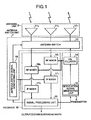
- Fig. 1 is a block diagram of a configuration of a monopulse radar apparatus according to the present invention.
- the radar apparatus shown in Fig. 1 is a configuration of a general monopulse radar apparatus.
- the monopulse radar apparatus according to the present invention has characteristics in the configuration of a transmission/reception antenna of the antenna unit, the configuration of an antenna switching unit, and the process of a signal processing unit performed based on these configurations.
- the reader needs to understand the configuration of a general monopulse radar apparatus. Therefore, a configuration and the like of the monopulse radar apparatus to which the present invention is applied are explained first.
- the monopulse radar apparatus shown in Fig. 1 includes processing units having processing functions divided in large blocks, that is, an antenna unit 6, an antenna switching unit 7, a transmitter 8, and a receiver 10.
- the antenna unit 6 includes transmission/reception antennas 11 1 , 11 2 , and 11 3 that function as transmission antennas or reception antennas.
- the antenna switching unit 7 includes an antenna switch 12 that switches a connection of the transmission/reception antennas 11 1 , 11 2 , and 11 3 to the transmitter 8 or to the receiver 10, and an antenna-switch-signal generating unit 19 that generates an antenna switch signal to switch the antenna switch 12.
- the transmitter 8 includes a modulation-signal generating unit 15 that generates various kinds of modulation signals (for example, an FM-CW modulation signal, and a pulse modulation signal) to generate a radar signal emitted from the antenna unit to the space, and an oscillator 14 that generates and outputs a radar signal modulated based on this modulation signal.
- a modulation-signal generating unit 15 that generates various kinds of modulation signals (for example, an FM-CW modulation signal, and a pulse modulation signal) to generate a radar signal emitted from the antenna unit to the space
- an oscillator 14 that generates and outputs a radar signal modulated based on this modulation signal.
- the receiver 10 includes RF mixers 16 (16 1 , 16 2 ) that are connected to any one of the transmission/reception antennas 11 1 , 11 2 , and 11 3 , respectively, and downconverts reception signals output from the transmission/reception antennas 11 1 , 11 2 , and 11 3 , based on a mixer signal (an RF local signal) of an RF band supplied from the oscillator 14, IF mixers 17 (17 1 , 17 2 ) that are connected to the RF mixers 16, respectively, and downconvert a downconverted signal into a baseband signal, based on a mixer signal (an IF local signal) of an IF band supplied from the antenna-switch-signal generating unit 19, and a signal processing unit 20 that performs various kinds of signal processes based on signals output from the IF mixers 17, and generates and outputs information of a distance, a speed, and an azimuth.
- the signal processing unit 20 also has a function of a control unit that controls the transmitter 8 and the antenna switching unit 7.
- Fig. 2 depicts a principle of an azimuth detection of a phase-comparison monopulse system.
- Fig. 3-1 to Fig. 3-3 depict a principle of an azimuth detection of an amplitude-comparison monopulse system. More specifically, Fig. 3-1 depicts two antenna patterns having center azimuths of antenna beams shifted. Fig. 3-2 depicts signal intensity of a sum signal ( ⁇ ) and a difference signal ( ⁇ ) that are generated based on the signals received by the antennas of the antenna pattern shown in Fig. 3-1. Fig. 3-3 depicts an angle error signal that is generated based on the sum signal ( ⁇ ) and the difference signal ( ⁇ ) shown in Fig. 3-2.
- the outputs of the two antennas are used to detect an angle error (a deviation from the antenna front surface direction).
- an output characteristic of the sum signal ( ⁇ ) as shown in Fig. 3-2 is obtained.
- an output characteristic of the difference signal ( ⁇ ) as shown in Fig. 3-2 is obtained.
- This difference signal ( ⁇ ) includes information of a deviation of a target antenna pattern, received by both reception antennas, from the center axis.
- the difference signal ( ⁇ ) is divided by the sum signal ( ⁇ ) that receives an influence similar to that of the difference signal ( ⁇ ) (namely, normalized), thereby obtaining an angle error signal that does not receive the influence of this variation, as shown in Fig. 3-3.
- This angle error signal becomes approximately an S curve.
- a configuration of a general plane antenna has a difficulty in that a pair of antennas that perform the monopulse process cannot be easily disposed at a desired distance (a distance in which a phase distortion does not occur).
- the size of the antenna is made smaller, the distance between the pair of antennas can be made smaller. In this case, the antenna gain becomes small, and the antenna beams are widened, thereby affecting the detection performance.
- the size of the antenna needs to be made smaller, and the antennas need to be arrayed. In arraying the antennas, the antennas need to be disposed to avoid a shift deviation, depending on a frequency band used.
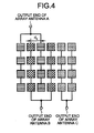
- Fig. 4 depicts an antenna configuration of the antenna unit according to the first embodiment.
- four antenna elements are arrayed at equal distances in up and down (elevation) directions, and six antenna elements are arrayed at equal distances (d 0 ) in left and right (azimuth) directions, as a plane antenna.
- the antenna elements are also arrayed in the elevation direction to narrow the antenna beams in the elevation direction, thereby increasing the radiation efficiency in the front surface direction.
- the radar processing technique according to the present invention can be also applied to both the elevation direction and the azimuth direction, there is no substantial difference of the application between both directions. Assuming the mounting of the monopulse radar apparatus according to the present embodiment to a vehicle, angle detection in the azimuth direction is explained below as an example.
- the antenna unit according to the present embodiment has a configuration, in which four antenna elements in the elevation direction are set as one antenna group. Two antenna element groups are combined together to configure three array antennas of an array antenna A, an array antenna B, and an array antenna C.
- the array antenna A includes a first and a third antenna element groups from the left, respectively.
- the array antenna B includes a second and a fourth antenna element groups from the left, respectively.
- the array antenna C includes a fifth and a sixth antenna element groups from the left, respectively.
- a distance between the antenna element groups (or an antenna element group width), which constitute the array antenna C is d 0 .
- a distance between the antenna element groups (or an antenna element group width) that constitute the array antenna A and the array antenna B, respectively is 2d 0 , thereby having a double distance of the distance between the antenna element groups of the array antenna C. Therefore, when the same antenna elements are used, the beam width of the array antenna C is larger than the beam width of the array antenna A or the array antenna B.
- a pair of comb-type array antennas are formed to have the antenna element groups of the array antenna A and the antenna element groups of the array antenna B that are disposed alternately, as shown in Fig. 4.
- a phase center of the array antenna A is near one antenna element group (the left antenna element group) of the array antenna B
- a phase center of the array antenna B is near one antenna element group (the right antenna element group) of the array antenna A. Therefore, the array antenna A and the array antenna B are set to have the same distance between the antennas as the antenna element distance d 0 .
- the array antenna C can be used as a transmission antenna, and the array antenna A and the array antenna B can be used as a pair of reception antennas that perform a monopulse signal process.
- the phase distortion of the monopulse signal process described above can be suppressed.
- Fig. 5 depicts another antenna configuration different from the configuration of the antenna unit shown in Fig. 4 according to the first embodiment.
- the antenna unit 6 has a configuration, in which four antenna elements in the elevation direction are set as one antenna group. Three antenna element groups are combined together to form three array antennas of the array antenna A, the array antenna B, and the array antenna C.
- the array antenna A includes a first, a third, and a fifth antenna element groups from the left, respectively.
- the array antenna B includes a second, a fourth, and a sixth antenna element groups from the left, respectively.
- the array antenna C includes a seventh to a ninth antenna element groups from the left, respectively.
- a distance between the antenna element groups that constitute the array antenna C is 2d 0 .
- a distance between the antenna element groups that constitute the array antenna A and the array antenna B, respectively is 4d 0 , thereby having a double distance of the distance between the antenna element groups of the array antenna C. Therefore, these antenna element groups have a relationship similar to that of the antenna unit shown in Fig. 4.
- a phase center of the array antenna A and a phase of the array antenna B are set to the same distance as the antenna element distance d 0 , like in the configuration of the antenna unit shown in Fig. 4. Therefore, when the array antenna A and the array antenna B are used as a pair of reception antennas that perform a monopulse signal process, the phase distortion of the monopulse signal process can be suppressed.
- the antenna unit is configured to have a function equivalent to that of the antenna unit shown in Fig. 4.
- Fig. 6 depicts detection areas of the array antennas shown in Fig. 4.
- the beam width of the array antenna C is larger than the beam width of the array antenna A or the array antenna B. Therefore, If1 that indicates the detection area of the array antenna C covers a larger range than K2 that indicates the detection area of the array antenna B or K3 that indicates the detection area of the array antenna A.
- the detection area of K2 is slightly shifted from the detection area K3 to facilitate the understanding of these areas, and these areas are substantially equal.
- the array antenna C is a transmission antenna
- the array antenna A and the array antenna B are used to perform a monopulse process.
- an azimuth angle of a target that is present in the area of the array antenna A (and the array antenna B) can be detected.
- the array antenna C is also used as a reception antenna.
- this target is present in the area of the array antenna C, and that this target is not present in the area of the array antenna A (and the array antenna B). In other words, this target is not present near the center of these areas.
- the target When a target is close, the target can be received in a sidelobe, even when the target is not present in the range of a beam half-maximum full-width of the array antenna A or the array antenna B. However, in this case, it is also clear that the target is not present near the center, based on the fact that the array antenna C receives this target.
- this detection area When a wide-range detection area is to be covered, this detection area is divided into plural areas in which a phase distortion does not easily occur. Any one of the above two processes is applied to each of the divided areas, while deviating the direction of a main beam of each antenna. With this arrangement, a correct azimuth without vagueness of angle can be detected. When the detection area is limited, angle precision of the detection azimuth within the detection area can be also improved.
- the distance between the antenna element groups that constitute the array antenna A and the distance between the antenna element groups that constitute the array antenna B, respectively are set to two times of the distance between the antenna element groups that constitute the array antenna C.
- the width of the antenna element groups that constitute the array antenna A and the width of the antenna element groups that constitute the array antenna B, respectively can be also set to two times of the width of the antenna element groups that constitute the array antenna C, thereby obtaining a similar effect.
- the distance or the width is not limited to the two times. What is important is that the beam pattern of the transmission antenna is formed larger than the beam pattern of the reception antenna, to satisfy the above process. In other words, it is sufficient to have a configuration including a transmission antenna having a wide beam pattern and a pair of reception antennas having a narrow beam pattern. Preferably, distances between the antenna element groups of the array antennas that constitute a pair of reception antennas are set the same, from the viewpoint of the same or equivalent beam patterns.
- a wide-beam array antenna and plural narrow-beam antennas are configured.
- the monopulse radar apparatus performs a monopulse process based on the output of a pair of array antennas out of the plural narrow-beam array antennas, among the configured array antennas. Therefore, constraints of mounting on the antenna can be limited, and a wide-range monopulse process becomes possible. Further, the antenna elements can be effectively disposed on the limited space. Furthermore, the mechanism of the antenna unit becomes simple.
- Fig. 7 depicts detection areas when the center directions of the array antenna A and the array antenna B shown in Fig. 6 are deviated to the left and right, respectively.
- the center directions of the array antenna A and the array antenna B are oriented to the same direction.
- the center directions of the array antenna A and the array antenna B are oriented to the left and right, respectively.
- Each processing unit including the antenna unit according to the present embodiment has the same configuration as the configuration of the corresponding processing unit of the first embodiment.
- a monopulse process according to the present embodiment is explained below.
- Fig. 7 first, assume that any one of the array antenna A, the array antenna B, and the array antenna C is used to transmit a beam, and that the array antenna A and the array antenna B are used to perform the monopulse process. In this case, an azimuth of a target that is present in a detection area R2 near the center of the area can be detected. Similarly, when any one of the array antenna A and the array antenna C is used to transmit a beam, and when the array antenna A and the array antenna C are used to perform the monopulse process, an azimuth of a target that is present at the left side can be detected.
- a pair of antennas (the array antennas A and B) having narrow beam patterns, with beam directions deviated to the left and right from the center direction, respectively, and an antenna (the array antenna C) having a wide beam pattern that covers beam patterns of the pair of antennas, with beam directions oriented to the center direction, are configured on the same plane antenna. Therefore, an antenna beam suitable for the monopulse process can be formed, without changing a layout of antenna elements that constitute the array antenna, and without particularly combining beams.
- this detection area When a wide-range detection area is to be covered, this detection area is divided into plural areas in which a phase distortion does not easily occur, like in the first embodiment. Any one of the above two processes is applied to each of the divided areas, while deviating the direction of a main beam of each antenna. With this arrangement, a correct azimuth without vagueness of angle can be detected. When the detection area is limited, angle precision of the detection azimuth within the detection area can be also improved.
- the distance between the antenna element groups that constitute the array antenna A and the distance between the antenna element groups that constitute the array antenna B, respectively are set to two times of the distance between the antenna element groups that constitute the array antenna C.
- the width of the antenna element groups that constitute the array antenna A and the width of the antenna element groups that constitute the array antenna B, respectively can be also set to two times of the width of the antenna element groups that constitute the array antenna C, thereby obtaining a similar effect.
- the distance or the width is not limited to the two times. What is important is that the beam pattern of the array antenna having a wide beam pattern substantially covers the beam patterns of a pair of array antennas having narrow beam patterns, with beam directions deviated to the left and right from the center direction, respectively.
- the distance between the antenna element groups of the array antenna having a wide beam pattern and the distance between the antenna element groups of the array antenna having a narrow beam pattern are related to beam eccentricities at the left and right of the array antenna having the narrow beam pattern and the beam pattern of the antenna element itself. Therefore, the antenna element and the distance between the antenna element groups can be determined based on these factors.
- distances between the antenna element groups of the array antennas that constitute a pair of array antennas are set the same, from the viewpoint of symmetrical beam patterns.
- a pair of antennas having a narrow beam pattern, with beam directions deviated from the center direction to the left and right or up and down, and an array antenna having a wide beam pattern that covers the beam patterns of the pair of antennas, with a beam direction oriented to the center direction are configured. Therefore, an antenna beam suitable for the monopulse process can be formed, without changing a layout of antenna elements that constitute the array antenna, and without particularly combining beams.
- Fig. 8 depicts an antenna configuration of an antenna unit according to a third embodiment.
- the antenna unit according to the present embodiment has antenna elements disposed to have a slightly larger distance between the second antenna element group and the third antenna element group from the left, respectively, than the distance between the second antenna element group and the third antenna element group from the left, respectively of the plane array antenna according to the first or the second embodiment.
- each array antenna has a configuration, in which four antenna elements in the elevation direction are set as an antenna element group.
- Three array antennas including an array antenna D, an array antenna E, and an array antenna F are configured, by combining two antenna element groups, respectively.
- the array antenna F includes the first and the second antenna element groups from the left, respectively
- the array antenna E includes the third and the fourth antenna element groups from the left, respectively
- the array antenna D includes the fifth and the sixth antenna element groups from the left, respectively.
- a relationship of d 1 ⁇ d 2 ⁇ d 3 is established between d 1 , d 2 , and d 3 , where d 1 represents a distance between the array antenna D and the array antenna E, d 2 represents a distance between the array antenna E and the array antenna F, and d 3 represents a distance between the array antenna D and the array antenna F.
- the three sets of a pair of array antennas, each pair having two array antennas configure arrays having unequal distances.
- a power feed line of one of the antenna element groups that constitute the array antenna F (the right-side antenna element group in Fig. 8) has a switch mechanism 30 that operates by receiving a control from the signal processing unit 20 not shown.
- the array antenna F is also used as a transmission antenna.
- the array antenna F functions as a transmission antenna, power is not supplied to one of the antenna element groups that constitutes the array antenna F, based on the operation of the switch mechanism 30, and the other antenna element group that constitutes the array antenna F (the left-side antenna element group in Fig. 8) irradiates a predetermined wave.
- the array antenna F functions as a reception antenna
- the two antenna element groups that constitute the array antenna F output reception waves to the output terminal of the antenna F, based on the operation of the switch mechanism 30. Therefore, the array antenna F has a function equivalent to the function of the array antennas D and E.
- the transmission antenna can be formed to have a wider beam pattern than the beam pattern of the reception antenna, like in the first and the second embodiments.
- any one of the six antenna element groups shown in Fig. 8 can be used. However, from the viewpoint of securing isolation between the transmission antenna and the reception antenna, it is suitable to use the most left-side antenna element group for the transmission antenna, in the configuration of the antenna unit shown in Fig. 8.
- Fig. 9 depicts another state of supplying power to each antenna element of the antenna unit according to the third embodiment.
- four antenna elements in the elevation direction are used as one antenna element group, and power is supplied to each antenna element group.
- each antenna element can be configured.
- a switch mechanism that switches between a power supply and a power non-supply to the four antenna element groups in the elevation direction is provided.
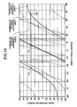
- Fig. 10 is a graph of one example of a relationship between an azimuth angle and a phase difference when a phase-comparison monopulse process is performed based on three sets of a pair of array antennas by combining two antennas out of the three antennas shown in Fig. 8.
- a curve shown in a solid line expresses a result of a phase-comparison monopulse process performed based on a combination of the array antenna D and the array antenna E.
- a curve shown in a dashed line expresses a result of a phase-comparison monopulse process performed based on a combination of the array antenna E and the array antenna F.
- a curve shown in a broken line expresses a result of a phase-comparison monopulse process performed based on a combination of the array antenna F and the array antenna D.
- phase-comparison monopulse process based on a combination of the array antenna E and the array antenna F having the distance d 2 is called a "second monopulse process”
- a phase-comparison monopulse process based on a combination of the array antenna D and the array antenna E having the distance d 1 is called a "third monopulse process”.
- the number of array antennas is set to four.
- the number of antenna elements in Fig. 8 is increased to configure a fourth array antenna, in addition to the array antennas D, E, and F.
- a monopulse process is performed based on a combination of antennas in which a distance d 4 between the fourth array antenna and other array antennas is d 4 ⁇ d 1 ,d 2 ,d 3 .
- array antennas having different antenna distances can be configured without increasing the number of antenna elements.
- a fifth array antenna including the fourth and the fifth antennas from the left, respectively is configured in Fig. 8
- a monopulse process can be performed, using these array antennas.
- the number of array antennas that becomes the base for performing these monopulse processes is not limited to the above three or four. It is needless to mention that five or more array antennas can be configured, and a monopulse process can be performed based on plural sets of a pair of array antennas by combining two array antennas out of these array antennas.
- an area in which signs of phase differences due to the first, the second, and the third monopulse processes all become positive is also present near an azimuth angle 50 degrees, in addition to the above 0 ⁇ 1 .
- Which one of these areas is to be selected is determined based on an antenna pattern. For example, when the antenna beam is oriented to a direction of 0 degree, and when a half-maximum full-width is about 20 degrees, a result of detection in the 0-degree direction can be employed.
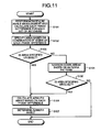
- Fig. 11 is a flowchart of the process performed by the signal processing unit based on the configuration of the antenna unit according to the third embodiment. This flowchart makes the above processing flow clear.
- the signal processing unit 20 shown in Fig. 1 performs these processes.
- the signal processing unit 20 performs a monopulse angle measurement for each set of array antennas (a combination of array antennas that perform the first, the second, or the third monopulse process), thereby calculating each phase difference (step S101).
- the signal processing unit 20 specifies an area in which there is a possibility of presence of a target, based on signs of these phase differences (step S102).
- the signal processing unit 20 determines whether an area having a possibility of presence of a target is uniquely specified (step S103).
- the signal processing unit 20 calculates an azimuth angle based on each phase difference (step S106), and determines an azimuth angle (step S107). In the determination of the azimuth angle at step S107, an average value of angles calculated at step S106, for example, can be employed.
- the signal processing unit 20 compares each angle calculated at step S106 with a detection result of the last scan, and can employ a value nearest the last result. When a future position is forecast using a speed or acceleration, a value nearest the forecast position can be employed.
- step S104 When an area cannot be specified uniquely (step S103, No), the signal processing unit 20 narrows down the selection based on an antenna pattern (step S104). The narrow-down process is as described above. The signal processing unit 20 determines again whether an area is specified uniquely, in a similar manner to that of the process at step S103 (step S105). When an area is specified uniquely (step S105, Yes), the process shifts to the process at step S106, and the signal processing unit 20 determines an azimuth direction. On the other hand, when an area cannot be specified uniquely (step S105, No), the signal processing unit 20 does not calculate or determine an azimuth angle in this detection process (scan).
- Fig. 12 is one example of a beam pattern of an antenna element that constitutes the antenna unit.
- step S104 in Fig. 11 a narrow-down process based on an antenna pattern is explained.
- an antenna pattern is understood in advance, and an area is specified using reception level information of an antenna.
- an area in which signs of phase differences due to the first, the second, and the third monopulse processes all become positive is also present near the azimuth angle 50 degrees, in addition to the above 0 ⁇ 1 , as shown in Fig. 10.
- a gain near 50 degrees becomes small, and a signal in the area having the same phase relationship cannot be received easily.
- a narrow-down process based on the antenna pattern at step S104 as shown in Fig. 11 does not need to be performed to at least a reception signal near 50 degrees.
- the layout of the antenna can be determined (or is determined) based on the beam pattern of the antenna element.
- the degree of freedom of the layout of antennas is larger than the degree of freedom of the design of antenna elements, depending on the platform on which the antenna unit is mounted or the frequency band to be used. In this case, a desired characteristic can be obtained easily and a flexible designing becomes possible, by determining the layout of antennas based on the beam pattern of the antenna element.
- the monopulse radar apparatus performs the monopulse process based on three or more sets of a pair of antennas having different distances between elements by combining two antennas out of three or more antennas that are configured in the antenna unit. Therefore, vagueness due to a phase distortion in the monopulse signal process can be eliminated.
- An antenna beam suitable for the monopulse process can be formed, without particularly changing a layout of antenna elements that constitute the array antenna, and without particularly combining beams.
- Fig. 13 is a flowchart of the process performed by the signal processing unit according to a fourth embodiment.
- a monopulse angle measurement is performed for each combination of array antennas based on which plural monopulse processes are performed.
- An area having a possibility of presence of a target is specified based on signs of detected phase differences. Thereafter, an azimuth angle in which a target is present is calculated.
- a monopulse angle measurement is performed for each combination of array antennas based on which plural monopulse processes are performed.
- Candidates of azimuth angles in which presence of a target is assumed are calculated for each phase difference. Azimuth angles that coincide are selected from among targets of the same speed and the same distance.
- the configuration of each processing unit including the antenna unit according to the present embodiment is the same as the configuration according to the third embodiment.
- the signal processing unit 20 shown in Fig. 1 performs these processes.
- the signal processing unit 20 performs a predetermined process including a monopulse angle measurement as a monopulse radar apparatus, from signals of the array antennas D and E.
- the signal processing unit 20 also calculates a distance and a speed of a target, and a phase difference x, and calculates an azimuth candidate ⁇ DE (x) corresponding to a phase difference x as an azimuth angle in which there is a possibility of presence of a target (step S201).
- the signal processing unit 20 similarly calculates an azimuth angle candidate ⁇ EF (y) corresponding to a phase difference y based on the array antennas E and F (step S202), and calculates an azimuth angle candidate ⁇ FD (z) corresponding to a phase difference z based on the array antennas F and D (step S203).
- the signal processing unit 20 selects azimuth angles that coincide with ⁇ DE (x), ⁇ EF (y), and ⁇ FD (z) calculated at steps S201 to S203, from data group of the same distance and the same speed, for the azimuth angle to be output (step S204).
- Fig. 14 depicts three candidate examples of a target azimuth angle calculated based on the combination of the array antennas D and E, on the graph shown in Fig. 10.
- a phase difference of a focused target is 90 degrees among plural targets detected based on the combination of the array antennas D and E
- three azimuth angles P1, P2, and P3 are calculated as the azimuth angle candidate ⁇ DE .
- azimuth angles that coincide with the azimuth angle candidate ⁇ DE and the azimuth angle candidate ⁇ EF in predetermined precision are selected from among the data group within predetermined distance precision and predetermined speed precision of the focused target, among plural targets detected based on the combination of the array antennas E and F.
- a similar process is also executed for the combination of the array antennas F and D. Through these processes, a set of a distance, a speed, and an azimuth angle is determined uniquely.
- the process can be started from any one of the processes at steps S201 to S203 shown in Fig. 13. While an azimuth angle is specified based on three sets of a pair of array antennas in the present embodiment, the number of sets is not limited to three. An azimuth angle can be specified using two or more sets of a pair of array antennas.
- the azimuth angle is specified based on the three sets of a pair of array antennas like in the present embodiment
- a comparison process of azimuth angle candidates is carried out once.
- an error probability of an azimuth angle is 0.05 (that is, one error per 20 times)
- a comparison process of azimuth angle candidates is executed twice.
- a monopulse process is performed based on two or more sets of a pair of antennas having different distances between elements by combining two antennas out of three or more antennas that are structured in the antenna unit. Therefore, vagueness due to a phase distortion in the monopulse signal process can be removed.
- An antenna beam suitable for the monopulse process can be formed, without particularly changing a layout of antenna elements that constitute the array antenna, and without particularly combining beams.
- Fig. 15-1 is a cross-sectional view of an approximate shape of an orthogonal cross-section that is orthogonal to both the antenna element layout surface and the antenna element groups of the antenna unit shown in Fig. 8.
- Fig. 15-1 also depicts outline antenna beams of the three array antennas (the array antennas D, E, and F) configured by two antenna element groups, respectively.
- Fig. 15-2 is a cross-sectional view of an approximate shape of an orthogonal cross-section that is orthogonal to both the antenna element layout surface and the antenna element groups of an antenna unit according to a fifth embodiment.
- Fig. 15-2 also depicts outline antenna beams of the three array antennas (the array antennas D, E, and F) configured by two antenna element groups, respectively. These antenna beams are substantially the same as the antenna beams shown in Fig. 15-1.
- the layout surface of the antenna elements (or the antenna element groups) that constitute the array antenna E is assumed as a "reference layout surface"
- the layout surface of the antenna elements that constitute the array antenna D is inclined by a predetermined angle of inclination ( ⁇ 1 ) in an azimuth right direction form the reference layout surface.
- the layout surface of the antenna elements that constitute the array antenna F is inclined by the predetermined angle of inclination ( ⁇ 1 ) in an azimuth left direction form the reference layout surface.
- the inclination angle ( ⁇ 1 ) is the angle formed by the beam center directions of the array antennas D and F relative to the beam center direction of the array antenna E.
- the beam center direction of the array antenna D can be rotated by the predetermined angle (an angle of eccentricity) ( ⁇ 1 ) to the azimuth right direction from the beam center direction of the array antenna E, without particularly combining directivity of the antenna element groups.
- the beam center direction of the array antenna F can be rotated by the predetermined angle of eccentricity ( ⁇ 1 ) to the azimuth left direction from the beam center direction of the array antenna E, without particularly combining directivity of the antenna element groups.
- the main beam direction of one array antenna is deviated to the left direction or the up direction from the center direction, out of three or more sets of a pair of array antennas.
- the layout surface of the antenna elements that constitute this array antenna is disposed by inclining the layout surface to the left direction or the up direction by a predetermined inclination angle from the reference layout surface.
- the main beam direction of the other array antenna is deviated to the right direction or the down direction from the center direction, out of the three or more sets of a pair of array antennas.
- the layout surface of the antenna elements that constitute this array antenna is disposed by inclining the layout surface to the right direction or the down direction by a predetermined inclination angle from the reference layout surface. Accordingly, the sidelobe can be controlled easily, without particularly combining directivity between the antenna element groups, and a stable characteristic can be obtained in the whole area of the detection range.
- the layout surfaces of the antenna elements that constitute the array antennas D and F are inclined by the same angle ( ⁇ 1 ) to the left and right directions, respectively, in rotating the beam center directions of the array antennas to the azimuth right direction and the azimuth left direction by the predetermined eccentricity angle ( ⁇ 1 ) from the beam center direction of the array antenna E.
- these inclination angles are not necessarily required to be the same angle ( ⁇ 1 ). What is important is that an inclination angle is set such that the control of the sidelobe of each array antenna becomes easy, and that a stable characteristic is obtained in the whole area of the detection range.
- the antenna elements are laid out on the inclination surface that is inclined to match the beam center direction of the antenna element.
- the antenna elements can be laid out on the surface having a predetermined curvature, or on a spherical surface, or on an oval spherical surface. In this case, an effect equivalent to that of the above can be obtained.
- Fig. 16-1 is a cross-sectional view of an approximate shape of an orthogonal cross-section that is orthogonal to both the antenna element layout surface and the antenna element groups of the antenna unit shown in Fig. 4.
- Fig. 16-1 also depicts outline antenna beams M1, M2, and M3 that correspond to the three array antennas A, B, and C configured by two antenna element groups, respectively.
- Fig. 16-2 is a cross-sectional view of an approximate shape of an orthogonal cross-section that is orthogonal to both the antenna element layout surface and the antenna element groups of an antenna unit according to a sixth embodiment.
- Fig. 16-2 also depicts the outline antenna beams M1, M2, and M3 that correspond to the three array antennas A, B, and C configured by two antenna element groups, respectively.
- These antenna beams are substantially the same as the antenna beams shown in Fig. 16-1.
- the array antenna A includes the first and the third antenna element groups from the left, respectively
- the array antenna B includes the second and the fourth antenna element groups from the left, respectively
- the array antenna C includes the fifth and the sixth antenna element groups from the left, respectively.
- the layout surface of the antenna elements that constitute the array antenna C is assumed as a "reference layout surface"
- the layout surface of the antenna elements that constitute the array antenna B is inclined by a predetermined angle of inclination ( ⁇ 2 ) in an azimuth left direction form the reference layout surface.
- the layout surface of the antenna elements that constitute the array antenna A is inclined by the predetermined angle of inclination ( ⁇ 2 ) in an azimuth right direction form the reference layout surface.
- the beam center direction of the array antenna A can be rotated by the predetermined angle of eccentricity ( ⁇ 2 ) to the azimuth right direction from the beam center direction of the array antenna C, without particularly combining directivity of the antenna element groups.
- the beam center direction of the array antenna B can be rotated by the predetermined angle of eccentricity ( ⁇ 2 ) to the azimuth right direction from the beam center direction of the array antenna C, without particularly combining directivity of the antenna element groups.
- the main beam direction of one array antenna is deviated to the left direction or the up direction from the center direction, out of a predetermined pair of array antennas.
- the layout surface of the antenna elements that constitute this array antenna is disposed by inclining the layout surface to the left direction or the up direction by a predetermined inclination angle from the reference layout surface.
- the main beam direction of the other array antenna is deviated to the right direction or the down direction from the center direction, out of the predetermined pair of array antennas.
- the layout surface of the antenna elements that constitute this array antenna is disposed by inclining the layout surface to the right direction or the down direction by a predetermined inclination angle from the reference layout surface. Accordingly, the sidelobe can be controlled easily, without particularly combining directivity between the antenna element groups, and a stable characteristic can be obtained in the whole area of the detection range.
- the layout surfaces of the antenna elements that constitute the array antennas A and B are inclined by the same angle ( ⁇ 2 ) to the left and right directions, respectively, in rotating the beam center directions of the array antennas to the azimuth left direction and the azimuth right direction by the predetermined eccentricity angle ( ⁇ 2 ) from the beam center direction of the array antenna C.
- these inclination angles are not necessarily required to be the same angle ( ⁇ 2 ). What is important is that an inclination angle is set such that the control of the sidelobe of each array antenna becomes easy, and that a stable characteristic is obtained in the whole area of the detection range.
- the switch control needs to be performed via the antenna switch 12 shown in Fig. 1, for example.
- the antenna-switch-signal generating unit 19 needs to transmit a necessary control signal to the antenna switch 12 and the reception unit.
- a configuration of the antenna switch 12 shown in Fig. 1 and one example of a control signal that is output from the antenna-switch-signal generating unit 19 are explained.
- An on-vehicle radar apparatus including an FM-CW radar that measures a distance between a vehicle and a target and a relative speed by using an electronic wave that is frequency-modulated by a triangular wave is used as an example for the explanation.
- the installation position of the on-vehicle radar apparatus is limited from the nature of the vehicle as a mounting platform.
- the installation area of plural antennas and the number of high-frequency parts required in the transmitting and receiver need to be decreased, to decrease sizes and weights of these parts to avoid the increase in the vehicle prices, from the viewpoint of securing competitiveness with other competitors.
- reduction of sizes and weights become effective techniques for various radar apparatuses as well as the on-vehicle radar apparatus.
- the antenna switch is a technique that achieves a further reduction in sizes and weights of radar apparatuses. From this viewpoint, a configuration and operation of the radar apparatus are explained below.
- Fig. 17 is a block diagram of a configuration of an on-vehicle FM-CW radar apparatus to which the antenna switch according to a seventh embodiment is applied.
- a voltage control oscillator (VCO) 110 outputs a triangular wave
- a multiplier (MLT) 112 multiplies a transmission signal FM modulated by the triangular wave, into a millimeter-wave band.
- a transmission amplifier 114 amplifies the millimeter-wave band, and inputs the amplified wave into an antenna switch 113.
- the antenna switch 113 transmits the wave from an antenna AT0 via an amplifier 115 and a switch 116.
- VCO voltage control oscillator
- MKT multiplier
- a switch 121 that blocks the entrance of a transmission signal to the reception side is provided between the antenna AT and an amplifier 124. When other unit can block the entrance of a signal to the reception side, the switches 116 and 121 are not always necessary.
- the amplifier 124 amplifies a reception signal received by each antenna.
- the switch 122 selects an amplified reception signal.
- a reception amplifier 126 amplifies the selected reception signal.
- a mixer 128 mixes this signal with a part of a transmission wave, and generates a beat signal.
- An analog-to-digital converter (ADC) 132 converts the beat signal generated by the mixer 128 into a digital signal.
- a fast Fourier transform (FFT) processing unit 134 high-speed Fourier transforms the digital signal, and inputs the Fourier-transformed signal to a central processing unit (CPU) 36.
- a mixer 131 is provided to cancel a frequency superimposed on the beat signal due to a switching between a transmission and a reception with a control signal SWR, by mixing the same frequency.
- on and off of the switch 116 is interlocked with on and off of the amplifier 115 that turns on and off a bias voltage.
- a selection performed by the switches 121 and 122 is interlocked with on and off of the amplifier 124.
- Fig. 18 depicts a waveform of the triangular wave that is input to the voltage control oscillator 10.
- columns A to C represent waveforms of control signals SWT, SWR, SW0, SW1, and SW2 in sections A to C shown in Fig. 18, respectively.
- a timescale of a horizontal axis of the graph in Fig. 18 is compressed considerably as compared with the timescale of the graphs shown in Fig. 19.
- data of the beat signal in the up section and the down section of a triangular wave generated from the reception signals of the reception antennas AT0 and AT1 are collected.
- a frequency of a peak that appears in the result of a Fourier transform is used to calculate a distance between the vehicle and the target and a relative speed.
- a phase of the peak is used to calculate a phase monopulse in the antennas AT0 and AT1.
- a transmission signal amplified by a first amplifier is supplied to one antenna via a second switch.
- a first switch selects any one of outputs of plural third amplifiers that amplify the output of a second amplifier that amplifies a reception signal of the one antenna, and reception signals of other plural antennas, respectively.
- the first switch supplies the selected output to the receiver. Therefore, the size and the weight of the antenna switch as a constituent part of the radar apparatus can be made smaller.
- a switch When a switch is used to decrease the number of antennas by sharing an antenna to transmit and receive signals and to decrease the number of high-frequency parts that are necessary for the transmitting and receiver by commonly processing the reception signals of plural reception antennas, a loss of a signal occurs due to the switch, and the performance becomes low. Therefore, when the switch is used, it is preferable to dispose the amplifier near the antenna.
- the monopulse radar apparatus is useful as a radar apparatus that detects a distance, a speed, and an azimuth of a mobile object.
- the monopulse radar apparatus is suitable when there is a space constraint in the antenna system or when the mechanism of the antenna system is to be simplified.
- the antenna switch according to the present invention contributes to decrease size and weight of the radar apparatus.
Landscapes
- Engineering & Computer Science (AREA)
- Radar, Positioning & Navigation (AREA)
- Remote Sensing (AREA)
- Physics & Mathematics (AREA)
- Electromagnetism (AREA)
- Computer Networks & Wireless Communication (AREA)
- General Physics & Mathematics (AREA)
- Radar Systems Or Details Thereof (AREA)
- Variable-Direction Aerials And Aerial Arrays (AREA)
Applications Claiming Priority (3)
| Application Number | Priority Date | Filing Date | Title |
|---|---|---|---|
| JP2004210440 | 2004-07-16 | ||
| JP2004228323 | 2004-08-04 | ||
| PCT/JP2005/013183 WO2006009122A1 (ja) | 2004-07-16 | 2005-07-15 | モノパルスレーダ装置およびアンテナ切換スイッチ |
Publications (3)
| Publication Number | Publication Date |
|---|---|
| EP1788408A1 true EP1788408A1 (de) | 2007-05-23 |
| EP1788408A4 EP1788408A4 (de) | 2013-01-16 |
| EP1788408B1 EP1788408B1 (de) | 2014-03-05 |
Family
ID=35785232
Family Applications (1)
| Application Number | Title | Priority Date | Filing Date |
|---|---|---|---|
| EP05766362.7A Expired - Fee Related EP1788408B1 (de) | 2004-07-16 | 2005-07-15 | Monopuls-radarvorrichtung und antennenwahlschalter |
Country Status (5)
| Country | Link |
|---|---|
| US (1) | US7612706B2 (de) |
| EP (1) | EP1788408B1 (de) |
| JP (1) | JPWO2006009122A1 (de) |
| CN (1) | CN1985187B (de) |
| WO (1) | WO2006009122A1 (de) |
Cited By (5)
| Publication number | Priority date | Publication date | Assignee | Title |
|---|---|---|---|---|
| DE102006042487A1 (de) * | 2006-09-07 | 2008-03-27 | S.M.S Smart Microwave Sensors Gmbh | Planarantennenanordnung |
| EP2068173A1 (de) * | 2007-12-04 | 2009-06-10 | Robert Bosch GmbH | Verfahren zur Messung von Querbewegungen in einem Fahrerassistenzsystem |
| WO2013056880A1 (de) * | 2011-10-17 | 2013-04-25 | Robert Bosch Gmbh | Winkelauflösender radarsensor |
| EP3376251A1 (de) * | 2017-03-14 | 2018-09-19 | Delphi Technologies LLC | Winkelfindung für einen detektor mit gepaartem gestaffelten array |
| WO2021138187A1 (en) * | 2019-12-30 | 2021-07-08 | Lyft, Inc. | Dynamic sparse radar array for scenarios |
Families Citing this family (85)
| Publication number | Priority date | Publication date | Assignee | Title |
|---|---|---|---|---|
| JP4516358B2 (ja) * | 2004-05-26 | 2010-08-04 | 富士通株式会社 | 無線基地局装置および無線通信方法 |
| EP1788407B1 (de) * | 2005-11-22 | 2015-05-27 | Fujitsu Ten Limited | Radarvorrichtung |
| JP5176314B2 (ja) * | 2006-12-15 | 2013-04-03 | 株式会社デンソー | レーダ装置 |
| JP4913646B2 (ja) * | 2007-03-26 | 2012-04-11 | 富士通テン株式会社 | レーダ装置、レーダ装置の制御装置、レーダ装置の制御プログラム、及びレーダ装置の制御方法 |
| US9733349B1 (en) | 2007-09-06 | 2017-08-15 | Rockwell Collins, Inc. | System for and method of radar data processing for low visibility landing applications |
| US9354633B1 (en) | 2008-10-31 | 2016-05-31 | Rockwell Collins, Inc. | System and method for ground navigation |
| US9939526B2 (en) | 2007-09-06 | 2018-04-10 | Rockwell Collins, Inc. | Display system and method using weather radar sensing |
| DE102007060769A1 (de) * | 2007-12-17 | 2009-06-18 | Robert Bosch Gmbh | Monostatischer Mehrstrahl-Radarsensor, sowie Verfahren |
| JP4828553B2 (ja) * | 2008-01-29 | 2011-11-30 | 富士通テン株式会社 | レーダ装置、及び物標の角度検出方法 |
| JP5184196B2 (ja) * | 2008-04-25 | 2013-04-17 | 富士通テン株式会社 | レーダ装置、レーダ装置の信号処理方法及び、車両制御システム |
| JP2009300102A (ja) * | 2008-06-10 | 2009-12-24 | Denso Corp | 方位検出装置、レーダ装置 |
| US8558731B1 (en) | 2008-07-02 | 2013-10-15 | Rockwell Collins, Inc. | System for and method of sequential lobing using less than full aperture antenna techniques |
| DE102008038365A1 (de) * | 2008-07-02 | 2010-01-07 | Adc Automotive Distance Control Systems Gmbh | Fahrzeug-Radarsystem und Verfahren zur Bestimmung einer Position zumindest eines Objekts relativ zu einem Fahrzeug |
| US8077078B1 (en) | 2008-07-25 | 2011-12-13 | Rockwell Collins, Inc. | System and method for aircraft altitude measurement using radar and known runway position |
| JP2010096589A (ja) * | 2008-10-15 | 2010-04-30 | Fujitsu Ten Ltd | 信号処理装置、レーダ装置、及び信号処理方法 |
| JP2010151496A (ja) * | 2008-12-24 | 2010-07-08 | Nippon Soken Inc | 方位検出装置 |
| JP5071414B2 (ja) * | 2009-03-04 | 2012-11-14 | 株式会社デンソー | レーダ装置 |
| WO2010115418A2 (de) | 2009-04-06 | 2010-10-14 | Conti Temic Microelectronic Gmbh | Radarsystem mit anordnungen und verfahren zur entkopplung von sende- und empfangssignalen sowie unterdrückung von störeinstrahlungen |
| FR2950147B1 (fr) * | 2009-09-15 | 2012-07-13 | Thales Sa | Radar a agilite de faisceau, notamment pour la fonction de detection et d'evitement d'obstacles |
| DE102009029503A1 (de) * | 2009-09-16 | 2011-03-24 | Robert Bosch Gmbh | Radarsensorvorrichtung mit wenigstens einer planaren Antenneneinrichtung |
| US8461965B2 (en) * | 2010-01-13 | 2013-06-11 | The Boeing Company | Portable radio frequency identification (RFID) reader |
| JP2011226794A (ja) * | 2010-04-15 | 2011-11-10 | Mitsubishi Electric Corp | レーダ装置 |
| US20110319034A1 (en) * | 2010-06-28 | 2011-12-29 | Boe Eric N | Method and system for propagation time measurement and calibration using mutual coupling in a radio frequency transmit/receive system |
| JP5472187B2 (ja) * | 2011-04-06 | 2014-04-16 | 株式会社デンソー | アンテナ装置 |
| US9019145B1 (en) | 2011-07-14 | 2015-04-28 | Rockwell Collins, Inc. | Ground clutter rejection for weather radar |
| JP5619705B2 (ja) * | 2011-10-20 | 2014-11-05 | 古河電気工業株式会社 | アンテナ装置 |
| FR2987683B1 (fr) * | 2012-03-02 | 2016-11-11 | Thales Sa | Radar a faible probabilite d'interception |
| JP5811931B2 (ja) * | 2012-04-04 | 2015-11-11 | トヨタ自動車株式会社 | 位相モノパルスレーダ装置 |
| US9547076B2 (en) | 2012-10-17 | 2017-01-17 | Raytheon Company | Elevation monopulse antenna synthesis for azimuth connected phase array antennas and method |
| JP6205729B2 (ja) * | 2013-01-21 | 2017-10-04 | 株式会社デンソー | レーダ装置 |
| DE102013205892A1 (de) | 2013-04-03 | 2014-10-09 | Robert Bosch Gmbh | Radarvorrichtung und Verfahren zum Betrieb einer Radarvorrichtung |
| US9262932B1 (en) | 2013-04-05 | 2016-02-16 | Rockwell Collins, Inc. | Extended runway centerline systems and methods |
| TWI495892B (zh) | 2013-09-13 | 2015-08-11 | Univ Nat Chiao Tung | 單脈衝雷達的比較器及其訊號產生方法 |
| CN104577356B (zh) * | 2013-10-12 | 2018-05-29 | 华为技术有限公司 | 天线系统和基站 |
| US9648504B2 (en) * | 2013-12-10 | 2017-05-09 | Qualcomm Incorporated | Using subarrays of a beamformer for transmissions in a forward link |
| DE102013113806A1 (de) * | 2013-12-11 | 2015-06-11 | Hella Kgaa Hueck & Co. | Radarvorrichtung und Verfahren hierfür |
| US10539670B2 (en) | 2014-01-23 | 2020-01-21 | Veoneer Us, Inc. | System and method for continuous wave interference cancellation |
| US9638794B2 (en) * | 2014-01-23 | 2017-05-02 | Autoliv Asp, Inc. | Systems and methods for correcting for leakage and distortion in radar systems |
| JP2015172491A (ja) * | 2014-03-11 | 2015-10-01 | 富士通テン株式会社 | アンテナ、レーダ装置、および、車両制御システム |
| US10928510B1 (en) | 2014-09-10 | 2021-02-23 | Rockwell Collins, Inc. | System for and method of image processing for low visibility landing applications |
| JP6393581B2 (ja) * | 2014-10-27 | 2018-09-19 | 株式会社デンソーテン | レーダ装置、および、信号処理方法 |
| JP2016201597A (ja) * | 2015-04-07 | 2016-12-01 | 株式会社東芝 | アレーアンテナ装置 |
| US10705201B1 (en) | 2015-08-31 | 2020-07-07 | Rockwell Collins, Inc. | Radar beam sharpening system and method |
| KR102438228B1 (ko) * | 2015-10-07 | 2022-08-31 | 주식회사 에이치엘클레무브 | 차량용 레이더 장치와 이를 이용한 타겟의 각도 추정 방법 |
| DE102015222884A1 (de) | 2015-11-19 | 2017-05-24 | Conti Temic Microelectronic Gmbh | Radarsystem mit verschachtelt seriellem Senden und parallelem Empfangen |
| TWI598611B (zh) * | 2015-11-25 | 2017-09-11 | 啟碁科技股份有限公司 | 雷達天線系統 |
| CN106850009B (zh) | 2015-11-30 | 2021-02-09 | 华为技术有限公司 | 一种确定通信波束的方法及对应装置 |
| TWI583055B (zh) * | 2015-12-15 | 2017-05-11 | 啟碁科技股份有限公司 | 陣列天線與天線系統 |
| CN106911013B (zh) * | 2015-12-23 | 2020-06-12 | 启碁科技股份有限公司 | 阵列天线与天线系统 |
| CN105589058B (zh) * | 2016-01-29 | 2019-05-31 | 宋春丽 | 一种天线装置及三维雷达系统 |
| US9846228B2 (en) | 2016-04-07 | 2017-12-19 | Uhnder, Inc. | Software defined automotive radar systems |
| US20170293024A1 (en) * | 2016-04-07 | 2017-10-12 | GM Global Technology Operations LLC | Cognitive transmission switching |
| WO2017175190A1 (en) | 2016-04-07 | 2017-10-12 | Uhnder, Inc. | Adaptive transmission and interference cancellation for mimo radar |
| US10261179B2 (en) | 2016-04-07 | 2019-04-16 | Uhnder, Inc. | Software defined automotive radar |
| WO2017187306A1 (en) | 2016-04-25 | 2017-11-02 | Uhnder, Inc. | Adaptive filtering for fmcw interference mitigation in pmcw radar systems |
| CN109073741B (zh) | 2016-04-25 | 2019-07-02 | 乌恩德股份有限公司 | 用于车辆的雷达感测系统及缓解其干扰的方法 |
| US10573959B2 (en) * | 2016-04-25 | 2020-02-25 | Uhnder, Inc. | Vehicle radar system using shaped antenna patterns |
| US9945935B2 (en) | 2016-04-25 | 2018-04-17 | Uhnder, Inc. | Digital frequency modulated continuous wave radar using handcrafted constant envelope modulation |
| US9791551B1 (en) | 2016-04-25 | 2017-10-17 | Uhnder, Inc. | Vehicular radar system with self-interference cancellation |
| US9806914B1 (en) | 2016-04-25 | 2017-10-31 | Uhnder, Inc. | Successive signal interference mitigation |
| EP3449272B1 (de) | 2016-04-25 | 2022-11-02 | Uhnder, Inc. | Fahrzeugradarsystem mit einem gemeinsamen radar und kommunikationssystem, und verfahren zur verwaltung eines solchen systems in einem fahrzeug |
| US10228460B1 (en) | 2016-05-26 | 2019-03-12 | Rockwell Collins, Inc. | Weather radar enabled low visibility operation system and method |
| US9753121B1 (en) | 2016-06-20 | 2017-09-05 | Uhnder, Inc. | Power control for improved near-far performance of radar systems |
| TWI629835B (zh) * | 2016-07-21 | 2018-07-11 | 和碩聯合科技股份有限公司 | 天線單元、天線系統及天線控制方法 |
| US10353068B1 (en) | 2016-07-28 | 2019-07-16 | Rockwell Collins, Inc. | Weather radar enabled offshore operation system and method |
| HUE049473T2 (hu) * | 2016-08-01 | 2020-09-28 | Grieshaber Vega Kg | Radaros feltöltési szintmérõ készülék |
| WO2018051288A1 (en) | 2016-09-16 | 2018-03-22 | Uhnder, Inc. | Virtual radar configuration for 2d array |
| US10481253B1 (en) * | 2016-11-02 | 2019-11-19 | L-3 Communications Corp. | Low-profile monopulse tracker |
| US11555917B2 (en) * | 2016-12-26 | 2023-01-17 | Mitsubishi Electric Corporation | Radar device |
| US10670695B2 (en) | 2017-02-10 | 2020-06-02 | Uhnder, Inc. | Programmable code generation for radar sensing systems |
| US10908272B2 (en) | 2017-02-10 | 2021-02-02 | Uhnder, Inc. | Reduced complexity FFT-based correlation for automotive radar |
| US11454697B2 (en) | 2017-02-10 | 2022-09-27 | Uhnder, Inc. | Increasing performance of a receive pipeline of a radar with memory optimization |
| KR102509019B1 (ko) * | 2017-02-21 | 2023-03-13 | 삼성전자 주식회사 | 최적 빔 표시 및 가이드 방법 및 장치 |
| KR102274959B1 (ko) * | 2017-03-09 | 2021-07-08 | 삼성전자주식회사 | 무선 통신 시스템에서 신호 검출을 위한 방법 및 장치 |
| JP6756300B2 (ja) * | 2017-04-24 | 2020-09-16 | 株式会社村田製作所 | アレーアンテナ |
| US11105890B2 (en) | 2017-12-14 | 2021-08-31 | Uhnder, Inc. | Frequency modulated signal cancellation in variable power mode for radar applications |
| CN110537106B (zh) * | 2018-03-27 | 2023-03-28 | 智能雷达系统有限公司 | 雷达装置 |
| US10756446B2 (en) * | 2018-07-19 | 2020-08-25 | Veoneer Us, Inc. | Planar antenna structure with reduced coupling between antenna arrays |
| CN109188374B (zh) * | 2018-07-25 | 2022-07-15 | 中国电子科技集团公司第二十九研究所 | 基于最前脉冲的复杂体制雷达全脉冲数字产生方法 |
| US11474225B2 (en) | 2018-11-09 | 2022-10-18 | Uhnder, Inc. | Pulse digital mimo radar system |
| WO2020183392A1 (en) | 2019-03-12 | 2020-09-17 | Uhnder, Inc. | Method and apparatus for mitigation of low frequency noise in radar systems |
| CN110174649A (zh) * | 2019-05-07 | 2019-08-27 | 加特兰微电子科技(上海)有限公司 | 射频前端收发装置、车载雷达收发系统 |
| CN110286372A (zh) * | 2019-07-19 | 2019-09-27 | 湖南华诺星空电子技术有限公司 | 一种空时虚拟阵mimo的fod雷达弱目标检测方法 |
| US20210215820A1 (en) | 2020-01-13 | 2021-07-15 | Uhnder, Inc. | Method and system for intefrence management for digital radars |
| JP7269914B2 (ja) * | 2020-12-11 | 2023-05-09 | 三菱重工業株式会社 | 方向探知装置、方向探知方法及び方向探知プログラム |
Citations (3)
| Publication number | Priority date | Publication date | Assignee | Title |
|---|---|---|---|---|
| US20030160718A1 (en) * | 2002-02-27 | 2003-08-28 | Hitachi, Ltd. | Monopulse radar system |
| US20030164791A1 (en) * | 2001-12-18 | 2003-09-04 | Hitachi, Ltd. | Monopulse radar system |
| DE10261027A1 (de) * | 2002-12-24 | 2004-07-08 | Robert Bosch Gmbh | Winkelauflösendes Antennensystem |
Family Cites Families (35)
| Publication number | Priority date | Publication date | Assignee | Title |
|---|---|---|---|---|
| JPH0587914A (ja) | 1991-08-07 | 1993-04-09 | Honda Motor Co Ltd | Fmレーダ装置 |
| JPH05100016A (ja) | 1991-10-14 | 1993-04-23 | Fujitsu Ltd | モノパルスレーダ受信機 |
| JP2757667B2 (ja) * | 1992-04-06 | 1998-05-25 | 三菱電機株式会社 | 飛しょう体用誘導装置 |
| JPH0720235A (ja) | 1993-06-30 | 1995-01-24 | Mitsubishi Electric Corp | モノパルス追尾装置 |
| JP3461911B2 (ja) * | 1994-05-20 | 2003-10-27 | 株式会社東芝 | フェーズドアレイアンテナ |
| JP3511329B2 (ja) * | 1995-06-09 | 2004-03-29 | 本田技研工業株式会社 | 車載用レーダ装置 |
| JP3498434B2 (ja) * | 1995-07-25 | 2004-02-16 | 株式会社デンソー | 開口面アンテナ、アンテナ駆動回路、及びレーダ装置 |
| JP3663703B2 (ja) * | 1995-12-05 | 2005-06-22 | 株式会社デンソー | モノパルスレーダ装置 |
| JP3663702B2 (ja) * | 1995-12-05 | 2005-06-22 | 株式会社デンソー | 平面アレーアンテナ及び位相モノパルスレーダ装置 |
| DE19648203C2 (de) * | 1996-11-21 | 1999-06-10 | Bosch Gmbh Robert | Mehrstrahliges Kraftfahrzeug-Radarsystem |
| KR20000069850A (ko) | 1997-01-21 | 2000-11-25 | 진 에이. 테넌트 | 충돌 예측 감지 시스템 |
| US6085151A (en) | 1998-01-20 | 2000-07-04 | Automotive Systems Laboratory, Inc. | Predictive collision sensing system |
| SE509278C2 (sv) * | 1997-05-07 | 1999-01-11 | Ericsson Telefon Ab L M | Radioantennanordning och förfarande för samtidig alstring av bred lob och smal peklob |
| JP3403607B2 (ja) | 1997-05-26 | 2003-05-06 | 富士通テン株式会社 | スキャンレーダ装置 |
| JP3597678B2 (ja) | 1997-08-18 | 2004-12-08 | 富士通株式会社 | レーダ装置 |
| JPH11133143A (ja) | 1997-10-31 | 1999-05-21 | Toyota Motor Corp | レーダ装置 |
| JP3525426B2 (ja) * | 1997-11-28 | 2004-05-10 | トヨタ自動車株式会社 | レーダ装置 |
| DE19754720C2 (de) | 1997-12-10 | 2000-12-07 | Adc Automotive Dist Control | Verfahren zum Betrieb eines Radarsystems |
| JPH11271435A (ja) | 1998-03-25 | 1999-10-08 | Toyota Central Res & Dev Lab Inc | モノパルス受信機 |
| JPH11281729A (ja) | 1998-03-31 | 1999-10-15 | Toyota Central Res & Dev Lab Inc | ビーム切替型レーダー装置 |
| JP3433417B2 (ja) * | 1998-04-02 | 2003-08-04 | トヨタ自動車株式会社 | レーダ装置 |
| JP2000090307A (ja) | 1998-09-10 | 2000-03-31 | Mitsubishi Electric Corp | ノンストップ自動料金収受システム |
| SE513136C2 (sv) * | 1998-11-20 | 2000-07-10 | Ericsson Telefon Ab L M | Förfarande och anordning vid radiokommunikation |
| JP2000230974A (ja) | 1999-02-09 | 2000-08-22 | Toyota Motor Corp | レーダ装置 |
| JP2000241537A (ja) * | 1999-02-24 | 2000-09-08 | Mitsubishi Electric Corp | Fm−cwレーダによる測角装置 |
| JP2000258524A (ja) | 1999-03-08 | 2000-09-22 | Toyota Motor Corp | レーダ装置 |
| US6697344B1 (en) | 1999-03-16 | 2004-02-24 | Northrop Grumman Corporation | Onboard initial entry processor for facilitating a satellite communication |
| JP2001289941A (ja) | 2000-04-04 | 2001-10-19 | Matsushita Electric Ind Co Ltd | 多アンテナレーダー装置 |
| JP2003248055A (ja) | 2001-12-18 | 2003-09-05 | Hitachi Ltd | モノパルスレーダシステム |
| JP4190335B2 (ja) * | 2003-04-03 | 2008-12-03 | 富士通テン株式会社 | レーダ装置及びその信号処理方法 |
| WO2005033728A2 (en) * | 2003-05-22 | 2005-04-14 | General Atomics | Ultra-wideband radar system using sub-band coded pulses |
| JP4067456B2 (ja) * | 2003-06-09 | 2008-03-26 | 富士通テン株式会社 | レーダ装置及びその信号処理制御方法 |
| JP2005156337A (ja) * | 2003-11-26 | 2005-06-16 | Hitachi Ltd | 車載用レーダ装置 |
| JP2006003097A (ja) | 2004-06-15 | 2006-01-05 | Fujitsu Ten Ltd | レーダ装置 |
| DE102005027653A1 (de) * | 2005-06-15 | 2006-12-21 | Robert Bosch Gmbh | Vorrichtung zur Ortung von Objekten im Toten Winkel eines Fahrzeugs |
-
2005
- 2005-07-15 EP EP05766362.7A patent/EP1788408B1/de not_active Expired - Fee Related
- 2005-07-15 WO PCT/JP2005/013183 patent/WO2006009122A1/ja active Application Filing
- 2005-07-15 CN CN2005800237410A patent/CN1985187B/zh not_active Expired - Fee Related
- 2005-07-15 JP JP2006529198A patent/JPWO2006009122A1/ja active Pending
- 2005-07-15 US US11/630,040 patent/US7612706B2/en active Active
Patent Citations (3)
| Publication number | Priority date | Publication date | Assignee | Title |
|---|---|---|---|---|
| US20030164791A1 (en) * | 2001-12-18 | 2003-09-04 | Hitachi, Ltd. | Monopulse radar system |
| US20030160718A1 (en) * | 2002-02-27 | 2003-08-28 | Hitachi, Ltd. | Monopulse radar system |
| DE10261027A1 (de) * | 2002-12-24 | 2004-07-08 | Robert Bosch Gmbh | Winkelauflösendes Antennensystem |
Non-Patent Citations (1)
| Title |
|---|
| See also references of WO2006009122A1 * |
Cited By (11)
| Publication number | Priority date | Publication date | Assignee | Title |
|---|---|---|---|---|
| DE102006042487A1 (de) * | 2006-09-07 | 2008-03-27 | S.M.S Smart Microwave Sensors Gmbh | Planarantennenanordnung |
| EP2068173A1 (de) * | 2007-12-04 | 2009-06-10 | Robert Bosch GmbH | Verfahren zur Messung von Querbewegungen in einem Fahrerassistenzsystem |
| US8112223B2 (en) | 2007-12-04 | 2012-02-07 | Robert Bosch Gmbh | Method for measuring lateral movements in a driver assistance system |
| WO2013056880A1 (de) * | 2011-10-17 | 2013-04-25 | Robert Bosch Gmbh | Winkelauflösender radarsensor |
| JP2014532183A (ja) * | 2011-10-17 | 2014-12-04 | ローベルト ボッシュ ゲゼルシャフト ミット ベシュレンクテル ハフツング | 角度分解能型レーダセンサ |
| US9810768B2 (en) | 2011-10-17 | 2017-11-07 | Robert Bosch Gmbh | Angle-resolving radar sensor |
| EP3376251A1 (de) * | 2017-03-14 | 2018-09-19 | Delphi Technologies LLC | Winkelfindung für einen detektor mit gepaartem gestaffelten array |
| US10416680B2 (en) | 2017-03-14 | 2019-09-17 | Aptiv Technologies Limited | Angle finding for a detector having a paired staggered array |
| US10809737B2 (en) | 2017-03-14 | 2020-10-20 | Aptiv Technologies Limited | Angle finding for a detector having a paired staggered array |
| WO2021138187A1 (en) * | 2019-12-30 | 2021-07-08 | Lyft, Inc. | Dynamic sparse radar array for scenarios |
| US11435438B2 (en) | 2019-12-30 | 2022-09-06 | Woven Planet North America, Inc. | Dynamic sparse radar array for scenarios |
Also Published As
| Publication number | Publication date |
|---|---|
| CN1985187A (zh) | 2007-06-20 |
| EP1788408A4 (de) | 2013-01-16 |
| EP1788408B1 (de) | 2014-03-05 |
| CN1985187B (zh) | 2012-05-16 |
| JPWO2006009122A1 (ja) | 2008-05-01 |
| US20070182619A1 (en) | 2007-08-09 |
| US7612706B2 (en) | 2009-11-03 |
| WO2006009122A1 (ja) | 2006-01-26 |
Similar Documents
| Publication | Publication Date | Title |
|---|---|---|
| EP1788408B1 (de) | Monopuls-radarvorrichtung und antennenwahlschalter | |
| US6067048A (en) | Radar apparatus | |
| JP5130079B2 (ja) | 電子走査式レーダ装置及び受信用アレーアンテナ | |
| US8941533B2 (en) | Method and device for detecting azimuth | |
| JP4737165B2 (ja) | レーダの物標検知方法、およびこの物標検知方法を用いたレーダ装置 | |
| JP4905457B2 (ja) | レーダの物標検知方法、およびこの物標検知方法を用いたレーダ装置 | |
| KR100749560B1 (ko) | 레이더장치 | |
| US8049660B2 (en) | Radar apparatus configured to suppress effects of grating lobes upon detection of direction of target based on phase difference between received reflected waves | |
| JP3433417B2 (ja) | レーダ装置 | |
| EP0913705B1 (de) | Radar mit frequenzmodulierten, kontinuierlichen Wellen | |
| JP3393204B2 (ja) | マルチビームレーダ装置 | |
| US11061109B2 (en) | Radar device | |
| US20080291088A1 (en) | Radar Apparatus | |
| WO2010143462A1 (ja) | レーダ装置 | |
| US20090231182A1 (en) | Radar Target Detecting Method, and Appartus Using the Target Detecting Method | |
| JP2009103457A (ja) | レーダ装置、および保持部材 | |
| WO2017061462A1 (ja) | アンテナ装置及び物標検出装置 | |
| JPH11326491A (ja) | レーダ装置の位相補正値決定方法 | |
| JP5667887B2 (ja) | アンテナ装置及びレーダ装置 | |
| JP2011226794A (ja) | レーダ装置 | |
| JP2010175471A (ja) | レーダ装置 | |
| JP2012168194A (ja) | レーダ装置 | |
| US20100271278A1 (en) | Bistatic array antenna and method | |
| JP5611608B2 (ja) | レーダ装置 | |
| JP2012028945A (ja) | パッチアンテナ |
Legal Events
| Date | Code | Title | Description |
|---|---|---|---|
| PUAI | Public reference made under article 153(3) epc to a published international application that has entered the european phase |
Free format text: ORIGINAL CODE: 0009012 |
|
| 17P | Request for examination filed |
Effective date: 20070202 |
|
| AK | Designated contracting states |
Kind code of ref document: A1 Designated state(s): DE FR GB |
|
| DAX | Request for extension of the european patent (deleted) | ||
| RBV | Designated contracting states (corrected) |
Designated state(s): DE FR GB |
|
| A4 | Supplementary search report drawn up and despatched |
Effective date: 20121217 |
|
| RIC1 | Information provided on ipc code assigned before grant |
Ipc: G01S 13/44 20060101AFI20121211BHEP Ipc: G01S 13/93 20060101ALN20121211BHEP Ipc: G01S 7/02 20060101ALI20121211BHEP Ipc: H01Q 25/02 20060101ALI20121211BHEP Ipc: H01Q 21/06 20060101ALI20121211BHEP Ipc: H01Q 3/30 20060101ALI20121211BHEP |
|
| GRAJ | Information related to disapproval of communication of intention to grant by the applicant or resumption of examination proceedings by the epo deleted |
Free format text: ORIGINAL CODE: EPIDOSDIGR1 |
|
| GRAP | Despatch of communication of intention to grant a patent |
Free format text: ORIGINAL CODE: EPIDOSNIGR1 |
|
| GRAP | Despatch of communication of intention to grant a patent |
Free format text: ORIGINAL CODE: EPIDOSNIGR1 |
|
| RIC1 | Information provided on ipc code assigned before grant |
Ipc: G01S 7/02 20060101ALI20130815BHEP Ipc: G01S 13/93 20060101ALN20130815BHEP Ipc: H01Q 3/30 20060101ALI20130815BHEP Ipc: G01S 13/44 20060101AFI20130815BHEP Ipc: H01Q 21/06 20060101ALI20130815BHEP Ipc: H01Q 25/02 20060101ALI20130815BHEP |
|
| INTG | Intention to grant announced |
Effective date: 20130909 |
|
| INTG | Intention to grant announced |
Effective date: 20130918 |
|
| RAP1 | Party data changed (applicant data changed or rights of an application transferred) |
Owner name: FUJITSU TEN, LTD. |
|
| GRAS | Grant fee paid |
Free format text: ORIGINAL CODE: EPIDOSNIGR3 |
|
| GRAA | (expected) grant |
Free format text: ORIGINAL CODE: 0009210 |
|
| AK | Designated contracting states |
Kind code of ref document: B1 Designated state(s): DE FR GB |
|
| REG | Reference to a national code |
Ref country code: GB Ref legal event code: FG4D |
|
| REG | Reference to a national code |
Ref country code: DE Ref legal event code: R096 Ref document number: 602005042852 Country of ref document: DE Effective date: 20140410 |
|
| REG | Reference to a national code |
Ref country code: DE Ref legal event code: R097 Ref document number: 602005042852 Country of ref document: DE |
|
| PLBE | No opposition filed within time limit |
Free format text: ORIGINAL CODE: 0009261 |
|
| STAA | Information on the status of an ep patent application or granted ep patent |
Free format text: STATUS: NO OPPOSITION FILED WITHIN TIME LIMIT |
|
| 26N | No opposition filed |
Effective date: 20141208 |
|
| REG | Reference to a national code |
Ref country code: DE Ref legal event code: R097 Ref document number: 602005042852 Country of ref document: DE Effective date: 20141208 |
|
| GBPC | Gb: european patent ceased through non-payment of renewal fee |
Effective date: 20140715 |
|
| REG | Reference to a national code |
Ref country code: FR Ref legal event code: ST Effective date: 20150331 |
|
| PG25 | Lapsed in a contracting state [announced via postgrant information from national office to epo] |
Ref country code: FR Free format text: LAPSE BECAUSE OF NON-PAYMENT OF DUE FEES Effective date: 20140731 Ref country code: GB Free format text: LAPSE BECAUSE OF NON-PAYMENT OF DUE FEES Effective date: 20140715 |
|
| PGFP | Annual fee paid to national office [announced via postgrant information from national office to epo] |
Ref country code: DE Payment date: 20150707 Year of fee payment: 11 |
|
| REG | Reference to a national code |
Ref country code: DE Ref legal event code: R119 Ref document number: 602005042852 Country of ref document: DE |
|
| PG25 | Lapsed in a contracting state [announced via postgrant information from national office to epo] |
Ref country code: DE Free format text: LAPSE BECAUSE OF NON-PAYMENT OF DUE FEES Effective date: 20170201 |