EP1756672B1 - Vacuum system for immersion photolithography - Google Patents
Vacuum system for immersion photolithography Download PDFInfo
- Publication number
- EP1756672B1 EP1756672B1 EP05747245A EP05747245A EP1756672B1 EP 1756672 B1 EP1756672 B1 EP 1756672B1 EP 05747245 A EP05747245 A EP 05747245A EP 05747245 A EP05747245 A EP 05747245A EP 1756672 B1 EP1756672 B1 EP 1756672B1
- Authority
- EP
- European Patent Office
- Prior art keywords
- gas
- liquid
- control
- pressure
- separating means
- Prior art date
- Legal status (The legal status is an assumption and is not a legal conclusion. Google has not performed a legal analysis and makes no representation as to the accuracy of the status listed.)
- Ceased
Links
- 238000000206 photolithography Methods 0.000 title claims abstract description 19
- 238000007654 immersion Methods 0.000 title description 7
- 239000007788 liquid Substances 0.000 claims abstract description 55
- 238000005086 pumping Methods 0.000 claims abstract description 45
- 239000012530 fluid Substances 0.000 claims abstract description 37
- 238000000605 extraction Methods 0.000 claims abstract description 27
- 239000012071 phase Substances 0.000 claims abstract description 18
- 230000001105 regulatory effect Effects 0.000 claims abstract description 8
- 239000007791 liquid phase Substances 0.000 claims abstract description 5
- 238000011144 upstream manufacturing Methods 0.000 claims abstract description 4
- 238000000034 method Methods 0.000 claims description 22
- 230000001276 controlling effect Effects 0.000 claims description 12
- 239000000284 extract Substances 0.000 claims description 3
- 238000000926 separation method Methods 0.000 claims description 3
- XLYOFNOQVPJJNP-UHFFFAOYSA-N water Substances O XLYOFNOQVPJJNP-UHFFFAOYSA-N 0.000 description 18
- 230000005540 biological transmission Effects 0.000 description 4
- 239000000203 mixture Substances 0.000 description 4
- 230000005855 radiation Effects 0.000 description 4
- 239000000463 material Substances 0.000 description 3
- 230000003287 optical effect Effects 0.000 description 3
- 229920002120 photoresistant polymer Polymers 0.000 description 3
- 230000035945 sensitivity Effects 0.000 description 3
- 238000007872 degassing Methods 0.000 description 2
- 238000012423 maintenance Methods 0.000 description 2
- 229920006395 saturated elastomer Polymers 0.000 description 2
- 239000004065 semiconductor Substances 0.000 description 2
- 238000010521 absorption reaction Methods 0.000 description 1
- 239000007864 aqueous solution Substances 0.000 description 1
- 230000008878 coupling Effects 0.000 description 1
- 238000010168 coupling process Methods 0.000 description 1
- 238000005859 coupling reaction Methods 0.000 description 1
- 230000007423 decrease Effects 0.000 description 1
- 238000005137 deposition process Methods 0.000 description 1
- 238000000671 immersion lithography Methods 0.000 description 1
- 238000004519 manufacturing process Methods 0.000 description 1
- 238000010943 off-gassing Methods 0.000 description 1
- 238000011084 recovery Methods 0.000 description 1
- 238000005389 semiconductor device fabrication Methods 0.000 description 1
- 229910021642 ultra pure water Inorganic materials 0.000 description 1
- 239000012498 ultrapure water Substances 0.000 description 1
Images
Classifications
-
- G—PHYSICS
- G03—PHOTOGRAPHY; CINEMATOGRAPHY; ANALOGOUS TECHNIQUES USING WAVES OTHER THAN OPTICAL WAVES; ELECTROGRAPHY; HOLOGRAPHY
- G03F—PHOTOMECHANICAL PRODUCTION OF TEXTURED OR PATTERNED SURFACES, e.g. FOR PRINTING, FOR PROCESSING OF SEMICONDUCTOR DEVICES; MATERIALS THEREFOR; ORIGINALS THEREFOR; APPARATUS SPECIALLY ADAPTED THEREFOR
- G03F7/00—Photomechanical, e.g. photolithographic, production of textured or patterned surfaces, e.g. printing surfaces; Materials therefor, e.g. comprising photoresists; Apparatus specially adapted therefor
- G03F7/20—Exposure; Apparatus therefor
-
- G—PHYSICS
- G03—PHOTOGRAPHY; CINEMATOGRAPHY; ANALOGOUS TECHNIQUES USING WAVES OTHER THAN OPTICAL WAVES; ELECTROGRAPHY; HOLOGRAPHY
- G03F—PHOTOMECHANICAL PRODUCTION OF TEXTURED OR PATTERNED SURFACES, e.g. FOR PRINTING, FOR PROCESSING OF SEMICONDUCTOR DEVICES; MATERIALS THEREFOR; ORIGINALS THEREFOR; APPARATUS SPECIALLY ADAPTED THEREFOR
- G03F7/00—Photomechanical, e.g. photolithographic, production of textured or patterned surfaces, e.g. printing surfaces; Materials therefor, e.g. comprising photoresists; Apparatus specially adapted therefor
- G03F7/70—Microphotolithographic exposure; Apparatus therefor
- G03F7/708—Construction of apparatus, e.g. environment aspects, hygiene aspects or materials
- G03F7/70858—Environment aspects, e.g. pressure of beam-path gas, temperature
-
- G—PHYSICS
- G03—PHOTOGRAPHY; CINEMATOGRAPHY; ANALOGOUS TECHNIQUES USING WAVES OTHER THAN OPTICAL WAVES; ELECTROGRAPHY; HOLOGRAPHY
- G03F—PHOTOMECHANICAL PRODUCTION OF TEXTURED OR PATTERNED SURFACES, e.g. FOR PRINTING, FOR PROCESSING OF SEMICONDUCTOR DEVICES; MATERIALS THEREFOR; ORIGINALS THEREFOR; APPARATUS SPECIALLY ADAPTED THEREFOR
- G03F7/00—Photomechanical, e.g. photolithographic, production of textured or patterned surfaces, e.g. printing surfaces; Materials therefor, e.g. comprising photoresists; Apparatus specially adapted therefor
- G03F7/70—Microphotolithographic exposure; Apparatus therefor
- G03F7/70216—Mask projection systems
- G03F7/70341—Details of immersion lithography aspects, e.g. exposure media or control of immersion liquid supply
-
- B—PERFORMING OPERATIONS; TRANSPORTING
- B01—PHYSICAL OR CHEMICAL PROCESSES OR APPARATUS IN GENERAL
- B01D—SEPARATION
- B01D57/00—Separation, other than separation of solids, not fully covered by a single other group or subclass, e.g. B03C
-
- G—PHYSICS
- G03—PHOTOGRAPHY; CINEMATOGRAPHY; ANALOGOUS TECHNIQUES USING WAVES OTHER THAN OPTICAL WAVES; ELECTROGRAPHY; HOLOGRAPHY
- G03F—PHOTOMECHANICAL PRODUCTION OF TEXTURED OR PATTERNED SURFACES, e.g. FOR PRINTING, FOR PROCESSING OF SEMICONDUCTOR DEVICES; MATERIALS THEREFOR; ORIGINALS THEREFOR; APPARATUS SPECIALLY ADAPTED THEREFOR
- G03F7/00—Photomechanical, e.g. photolithographic, production of textured or patterned surfaces, e.g. printing surfaces; Materials therefor, e.g. comprising photoresists; Apparatus specially adapted therefor
- G03F7/70—Microphotolithographic exposure; Apparatus therefor
- G03F7/708—Construction of apparatus, e.g. environment aspects, hygiene aspects or materials
- G03F7/70808—Construction details, e.g. housing, load-lock, seals or windows for passing light in or out of apparatus
- G03F7/70841—Constructional issues related to vacuum environment, e.g. load-lock chamber
Definitions
- This invention relates to a vacuum system for extracting a multi-phase fluid from an immersion photolithography exposure tool.
- Photolithography is an important process step in semiconductor device fabrication.
- a circuit design is transferred to a wafer through a pattern imaged on to a photoresist layer deposited on the wafer surface.
- the wafer then undergoes various etch and deposition processes before a new design is transferred to the wafer surface. This cyclical process continues, building up the multiple layers of the semiconductor device.
- W k 1 ⁇ ⁇ NA
- k 1 the resolution factor
- ⁇ the wavelength of the exposing radiation
- NA the numerical aperture
- NA n ⁇ sin ⁇
- Immersion photolithography is a known technique for improving optical resolution by increasing the value of NA, as well as increasing the depth of focus (DOF) or vertical process latitude.
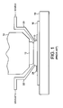
- a liquid 10 having a refractive index n > 1 is placed between the lower surface of the objective lens 12 of a projection device 14 and the upper surface of a wafer 16 located on a moveable wafer stage 18.
- the liquid placed between lens 12 and wafer 16 should, ideally, have a low optical absorption at 193nm, be compatible with the lens material and the photoresist deposited on the wafer surface, and have good uniformity.
- ultra-pure, degassed water which has a refractive index n ⁇ 1.44 for light at 193 nm.
- n refractive index
- the lens and wafer could be immersed in a bath of water supported by the wafer stage, with a pump used to recirculate the water within the bath.
- this technique is generally considered undesirable.
- An alternative technique is to use a nozzle or showerhead device 20 connected to a water source and a vacuum system, shown generally at 22, to produce a localised stream of ultra-pure, degassed water between the lens 12 and the wafer 16.
- a vacuum system shown generally at 22
- the vacuum system 22 extracts from the tool a multi-phase mixture of water and CDA.
- the extraction of such a multi-phase mixture from the tool using a single vacuum pump, especially in slug or churn regime flows can generate undesirable pressure and flow fluctuations upstream of the pump, which could be transmitted back to the tool. This could lead to errors in the photolithography process, for example, through variations in the refractive index of the medium located between the lens and the wafer, or through the transmission of mechanical vibrations to the tool.
- WO 2005/111 722 A which belongs to the prior art according to Article 54(3) EPC, discloses (paragraph 37, Figure 6) a wet porous member 51 for retaining gas in the immersion fluid.
- a recovery flow line 106 is connected to the porous member 51.
- WO 2005/015 315 A which belongs to the prior art according to Article 54(3) EPC, discloses ( Figures 2 , 3) a system for extracting a stream of multi-phase fluid from a photo-lithography tool, the system comprising separating means 44 located downstream from a pumping arrangement 68.
- EP 1 571 701 A which belongs to the prior art according to Article 54(3) EPC, discloses ( Figures 2 , 3, 6) a degassing unit 24 located downstream from a pumping arrangement 15.
- JP 08 000 907 A discloses ( Figure 1 ) a degassing device wherein the pressure of the device is controlled by a vacuum pump 4.
- the present invention provides a system for extracting a stream of multi-phase fluid from a photo-lithography tool, the system comprising a pumping arrangement for drawing the fluid from the tool, separating means, for example, an extraction tank, located upstream from the pumping arrangement for separating the fluid drawn from the tool into gas and liquid phases, the pumping arrangement comprising a first pumping unit arranged to extract gas from the tank and a second pumping unit arranged to extract liquid from the tank, and a pressure control system arranged to control the pressure within the tank by regulating the amounts of gas and liquid therewithin.
- separating means for example, an extraction tank, located upstream from the pumping arrangement for separating the fluid drawn from the tool into gas and liquid phases
- the pumping arrangement comprising a first pumping unit arranged to extract gas from the tank and a second pumping unit arranged to extract liquid from the tank, and a pressure control system arranged to control the pressure within the tank by regulating the amounts of gas and liquid therewithin.
- the pressure control system can maintain a substantially constant pressure in the tank by regulating the amounts of liquid and gas within the tank.
- the pressure control system preferably comprises means for supplying gas to the tank from a source thereof, and control means for controlling the flow of gas to the tank.
- control means for controlling the flow of gas to the tank.
- gas can be introduced into the tank from the external source to compensate for such variations.
- the pressure control system comprises a variable flow control device, such as a butterfly or other control valve, through which gas is supplied to the tank, with the control means being configured to vary the conductance of the valve to control the pressure within the tank.
- a controller may be configured to receive a signal indicative of the pressure within the tank, and to control the conductance of the valve in dependence on the received signal. This signal may be received from a pressure sensor, capacitance manometer or other form of sensor of sufficient sensitivity to achieve the required level of pressure control.
- the controller is preferably configured to control the flow of gas from the tank in dependence on the received signal.
- another variable flow control device may be provided, through which gas is extracted from the tank by the first pumping unit, with the controller being configured to control the conductance of this variable flow control device.
- the pressure control system preferably comprises means for supplying liquid to the tank from a source thereof, and control means for controlling the flow of liquid to the tank.
- the control means is preferably configured to maintain a substantially constant level of liquid within the tank.
- the liquid supply means comprises a variable flow control device such as a butterfly or other control valve, through which liquid is supplied to the tank, with the control means being configured to vary the conductance of the valve to control the level of liquid within the tank.
- a controller may be configured to receive a signal indicative of the level of liquid within the tank, and to control the conductance of the valve in dependence on the received signal.
- This signal may be received from a level meter, float detector, or other form of sensor of sufficient sensitivity to allow a substantially constant level of liquid to be maintained within the tank.
- One or more flexible tubes are preferably used to convey fluid (single and/or multi-phase) between the components of the system.
- a flexible tube may be used to convey the multi-phase fluid to the extraction tank.
- Further flexible tubes may also be used to convey the single phase streams from the tank to respective pumping units. This can minimise the transmission of vibrations generated during use of the system back to the fluid within the tool.
- the present invention provides a method of extracting a stream of multi-phase fluid from a photo-lithography tool, the method comprising the steps of: connecting a pumping arrangement to the tool via an extraction tank; operating the pumping arrangement to draw the fluid from the tool; separating the fluid drawn from the tool into gas and liquid phases within the extraction tank, the pumping arrangement extracting separately gas and liquid from the extraction tank; and controlling the pressure within the extraction tank by regulating the amounts of gas and liquid therewithin.
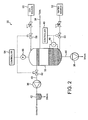
- a system 30 for extracting a multi-phase fluid from an immersion photolithography tool comprises an extraction tank 32 for receiving the multi-stream fluid drawn from the tool by a pumping arrangement located downstream from the tank 32.
- the tank 32 is connected to the tool by flexible tubing 34 so as to minimise the amount of mechanical coupling between the system 30 and the tool, and thereby minimise the transmission of vibrations generated during use of the system 30 back to the tool.
- the tank 32 is configured to separate the liquid and gas phases within the fluid received from the tool.
- the fluid received from the tool comprises a mixture of clean dry air (CDA) and ultra-pure water, and so the tank 32 contains any suitable material and/or structure for affecting the separation of the CDA from the water.
- the tank 32 may be configured to separate a different liquid-gas mixture received from the tool.
- the liquid may comprise an aqueous or non-aqueous solution, and the gas may be other than CDA.
- the pumping arrangement comprises a first pumping unit 36 for extracting gas from the tank 32, and a second pumping unit 38 for extracting liquid from the tank 32.
- the first pumping unit 36 may comprise any suitable pump for extracting the gas from the tank 32, and is preferably chosen for compatibility with the gas extracted from the tank 32, which is likely to be saturated with liquid vapour, for minimum transmission of pressure fluctuations back to the gas contained in the tank 32, and for relatively long maintenance periods.
- the first pumping unit 36 may conveniently comprise an air-powered ejector pump or a water-based liquid ring pump for extracting CDA from the tank 32.
- the first pumping unit 36 is connected to the tank using flexible tubing 40.
- a separator vessel 42 may be connected to the exhaust of the first pumping unit 36, the vessel 42 containing any suitable material and/or structure for affecting the separation of water vapour from the CDA.
- the water extracted from the CDA is exhaust to a drain, and the CDA is vented to the atmosphere.
- the second pumping unit 38 may comprise any suitable pump for extracting the liquid from the tank 32, and is preferably chosen for compatibility with the liquid extracted from the tank 32 and for relatively long maintenance periods.
- the second pumping unit 38 may conveniently comprise a water-powered ejector pump or a diaphragm pump for extracting water from the tank 32.
- the second pumping unit 38 is connected to the tank using flexible tubing 44.
- the internal diameter of the flexible tubing 44 may be chosen to restrict the flow rate of liquid from the tank 32 to the second pumping unit 38.
- a fixed or variable flow restrictor may be located between the tank 32 and the second pumping unit 38.
- the system 30 includes a pressure control system for maintain a substantially constant pressure in the tank 32. In this embodiment, this is achieved by regulating the amounts of liquid and gas within the tank 32.
- the amount of liquid contained in the tank 32 is maintained at a substantially constant level by a controller 46, thereby maintaining a substantially constant volume of gas in the tank 32.
- the controller 46 is connected to a sensor 48 for detecting the level of liquid with the tank 32.
- the sensor 48 may comprise, for example, a level meter, float meter or other form of suitable sensor.
- the sensor 48 outputs a signal to the controller 46 indicative of the level of the liquid within the tank 32.
- the controller 46 outputs to a variable flow control device 50 located between the tank 32 and a pressurised external liquid source 52 connected to the tank 32 a signal which causes the device 50 to vary the flow of liquid, in this embodiment water, to the tank 32.
- the device 50 may be a butterfly or other control valve having a conductance that can be varied in dependence on, preferably in proportion to, the signal received from the controller 46.
- the controller 46 can compensate for any variation in the flow rate of fluid to the tank 32 from the tool and/or any variation in the rate of extraction of liquid from the tank 32 by the second pumping unit 38, and thus maintain the liquid in the tank 32 at a substantially constant level.
- the controller 46 may be arranged to process the signal received from the sensor 48 to compensate for any ripples generated in the surface of the liquid during use.
- any variations in the amount of gas contained in the multi-phase fluid received from the tank, and/or any in the rate of extraction of gas from the tank 32 by the first pumping unit 36, and any temperature fluctuations within the tank 32, could vary the pressure of the gas within the tank 32, and impart pressure and flow fluctuations to the fluid in the tool.
- the pressure control system is therefore configured to maintain a substantially constant pressure within the tank 32 by also regulating the amount of gas within the tank 32.
- the pressure control system comprises a controller 54 connected to a sensor 56 for detecting the gas pressure with the tank 32.
- the sensor 56 may comprise, for example, a pressure sensor, a capacitance manometer or other form of sensor of sufficient sensitivity to achieve the required level of pressure control.
- the sensor 56 outputs a signal to the controller 54 indicative of the gas pressure within the tank 32.
- the controller 54 outputs to a variable flow control device 58 located between the tank 32 and a pressurised external gas source 60 connected to the tank 32 a signal which causes the device 58 to vary the flow of gas, in this embodiment CDA, to the tank 32.
- a further variable flow control device 62 may be located between the tank 32 and the first pumping unit 36 and configured to receive a signal from the controller 54 to vary the flow of gas from the tank 32.
- the devices 58, 62 may also be butterfly or other control valves having a conductance that can be varied in dependence on, preferably in proportion to, the signal received from the controller 54. By controlling the flow of gas into and out from the tank 32, the controller 54 can maintain a substantially constant gas pressure within the tank 32.
- the system 30 can thus provide a system capable of extracting a multi-phase fluid from the immersion lithography tool whilst minimising any pressure fluctuations imparted thereby to the fluid within the tool.
Landscapes
- Physics & Mathematics (AREA)
- General Physics & Mathematics (AREA)
- Health & Medical Sciences (AREA)
- Environmental & Geological Engineering (AREA)
- Engineering & Computer Science (AREA)
- Epidemiology (AREA)
- Public Health (AREA)
- Atmospheric Sciences (AREA)
- Life Sciences & Earth Sciences (AREA)
- Toxicology (AREA)
- Chemical Kinetics & Catalysis (AREA)
- Chemical & Material Sciences (AREA)
- Exposure And Positioning Against Photoresist Photosensitive Materials (AREA)
- Exposure Of Semiconductors, Excluding Electron Or Ion Beam Exposure (AREA)
- Crystals, And After-Treatments Of Crystals (AREA)
- Physical Or Chemical Processes And Apparatus (AREA)
- Degasification And Air Bubble Elimination (AREA)
Applications Claiming Priority (2)
| Application Number | Priority Date | Filing Date | Title |
|---|---|---|---|
| US10/869,191 US7481867B2 (en) | 2004-06-16 | 2004-06-16 | Vacuum system for immersion photolithography |
| PCT/GB2005/002205 WO2005124464A2 (en) | 2004-06-16 | 2005-06-06 | Vacuum system for immersion photolithography |
Publications (2)
| Publication Number | Publication Date |
|---|---|
| EP1756672A2 EP1756672A2 (en) | 2007-02-28 |
| EP1756672B1 true EP1756672B1 (en) | 2010-04-14 |
Family
ID=32851367
Family Applications (1)
| Application Number | Title | Priority Date | Filing Date |
|---|---|---|---|
| EP05747245A Ceased EP1756672B1 (en) | 2004-06-16 | 2005-06-06 | Vacuum system for immersion photolithography |
Country Status (10)
Families Citing this family (35)
| Publication number | Priority date | Publication date | Assignee | Title |
|---|---|---|---|---|
| EP1646075B1 (en) | 2003-07-09 | 2011-06-15 | Nikon Corporation | Exposure apparatus and device manufacturing method |
| KR20190002749A (ko) * | 2003-07-28 | 2019-01-08 | 가부시키가이샤 니콘 | 노광 장치 및 디바이스 제조 방법, 그리고 노광 장치의 제어 방법 |
| CN101430508B (zh) * | 2003-09-03 | 2011-08-10 | 株式会社尼康 | 为浸没光刻提供流体的装置和方法 |
| EP1747499A2 (en) | 2004-05-04 | 2007-01-31 | Nikon Corporation | Apparatus and method for providing fluid for immersion lithography |
| KR101264936B1 (ko) * | 2004-06-04 | 2013-05-15 | 가부시키가이샤 니콘 | 노광 장치, 노광 방법 및 디바이스 제조 방법 |
| KR101612656B1 (ko) * | 2004-06-10 | 2016-04-15 | 가부시키가이샤 니콘 | 노광 장치, 노광 방법 및 디바이스 제조 방법 |
| US8373843B2 (en) * | 2004-06-10 | 2013-02-12 | Nikon Corporation | Exposure apparatus, exposure method, and method for producing device |
| US8717533B2 (en) * | 2004-06-10 | 2014-05-06 | Nikon Corporation | Exposure apparatus, exposure method, and method for producing device |
| US8508713B2 (en) * | 2004-06-10 | 2013-08-13 | Nikon Corporation | Exposure apparatus, exposure method, and method for producing device |
| US20070139628A1 (en) * | 2004-06-10 | 2007-06-21 | Nikon Corporation | Exposure apparatus, exposure method, and method for producing device |
| US7481867B2 (en) * | 2004-06-16 | 2009-01-27 | Edwards Limited | Vacuum system for immersion photolithography |
| US7701550B2 (en) | 2004-08-19 | 2010-04-20 | Asml Netherlands B.V. | Lithographic apparatus and device manufacturing method |
| US7379155B2 (en) | 2004-10-18 | 2008-05-27 | Asml Netherlands B.V. | Lithographic apparatus and device manufacturing method |
| US7397533B2 (en) | 2004-12-07 | 2008-07-08 | Asml Netherlands B.V. | Lithographic apparatus and device manufacturing method |
| SG124351A1 (en) | 2005-01-14 | 2006-08-30 | Asml Netherlands Bv | Lithographic apparatus and device manufacturing method |
| US8692973B2 (en) | 2005-01-31 | 2014-04-08 | Nikon Corporation | Exposure apparatus and method for producing device |
| EP1863070B1 (en) | 2005-01-31 | 2016-04-27 | Nikon Corporation | Exposure apparatus and method for manufacturing device |
| US8018573B2 (en) * | 2005-02-22 | 2011-09-13 | Asml Netherlands B.V. | Lithographic apparatus and device manufacturing method |
| US7433016B2 (en) | 2005-05-03 | 2008-10-07 | Asml Netherlands B.V. | Lithographic apparatus and device manufacturing method |
| US8514365B2 (en) * | 2007-06-01 | 2013-08-20 | Asml Netherlands B.V. | Lithographic apparatus and device manufacturing method |
| US7924404B2 (en) * | 2007-08-16 | 2011-04-12 | Asml Netherlands B.V. | Lithographic apparatus and device manufacturing method |
| NL1036306A1 (nl) | 2007-12-20 | 2009-06-23 | Asml Netherlands Bv | Lithographic apparatus and in-line cleaning apparatus. |
| NL2003226A (en) | 2008-08-19 | 2010-03-09 | Asml Netherlands Bv | Lithographic apparatus, drying device, metrology apparatus and device manufacturing method. |
| JP2010098172A (ja) * | 2008-10-17 | 2010-04-30 | Canon Inc | 液体回収装置、露光装置及びデバイス製造方法 |
| JP5001343B2 (ja) * | 2008-12-11 | 2012-08-15 | エーエスエムエル ネザーランズ ビー.ブイ. | 流体抽出システム、液浸リソグラフィ装置、及び液浸リソグラフィ装置で使用される液浸液の圧力変動を低減する方法 |
| NL2004820A (en) * | 2009-06-30 | 2011-01-04 | Asml Netherlands Bv | Lithographic apparatus and a method of measuring flow rate in a two phase flow. |
| US20110211911A1 (en) * | 2010-03-01 | 2011-09-01 | Wavefront Technology Solutions Inc. | Method and apparatus for enhancing multiphase extraction of contaminants |
| US20120012191A1 (en) * | 2010-07-16 | 2012-01-19 | Nikon Corporation | Liquid recovery apparatus, exposure apparatus, liquid recovering method, device fabricating method, program, and storage medium |
| NL2009899A (en) | 2011-12-20 | 2013-06-24 | Asml Netherlands Bv | A pump system, a carbon dioxide supply system, an extraction system, a lithographic apparatus and a device manufacturing method. |
| CN104035288A (zh) * | 2014-06-05 | 2014-09-10 | 浙江大学 | 用于浸没式光刻机中的负压环境下的连续气液分离装置 |
| WO2016017700A1 (ja) * | 2014-07-31 | 2016-02-04 | 株式会社オプトクリエーション | 洗浄装置 |
| JP6535649B2 (ja) * | 2016-12-12 | 2019-06-26 | 株式会社荏原製作所 | 基板処理装置、排出方法およびプログラム |
| CN112684675B (zh) * | 2020-12-30 | 2023-02-21 | 浙江启尔机电技术有限公司 | 真空系统及使用该真空系统的浸没式光刻机 |
| TW202439039A (zh) * | 2023-03-21 | 2024-10-01 | 聯華電子股份有限公司 | 微影機台系統及其液體儲存槽的漏液檢測方法 |
| WO2024208512A1 (en) | 2023-04-04 | 2024-10-10 | Asml Netherlands B.V. | Fluid handling system and method, and method of manufacturing devices |
Citations (4)
| Publication number | Priority date | Publication date | Assignee | Title |
|---|---|---|---|---|
| JPH08907A (ja) * | 1994-06-17 | 1996-01-09 | Miura Co Ltd | 真空脱気における脱気度調整方法 |
| WO2005015315A2 (de) * | 2003-07-24 | 2005-02-17 | Carl Zeiss Smt Ag | Mikrolithographische projektionsbelichtungsanlage sowie verfahren zum einbringen einer immersionsflüssigkeit in einem immersionsraum |
| EP1571701A1 (en) * | 2002-12-10 | 2005-09-07 | Nikon Corporation | Exposure apparatus and method for manufacturing device |
| WO2005111722A2 (en) * | 2004-05-04 | 2005-11-24 | Nikon Corporation | Apparatus and method for providing fluid for immersion lithography |
Family Cites Families (132)
| Publication number | Priority date | Publication date | Assignee | Title |
|---|---|---|---|---|
| US3314219A (en) * | 1965-03-10 | 1967-04-18 | Bass Brothers Entpr Inc | Drilling mud degassers for oil wells |
| GB1242527A (en) * | 1967-10-20 | 1971-08-11 | Kodak Ltd | Optical instruments |
| US3573975A (en) * | 1968-07-10 | 1971-04-06 | Ibm | Photochemical fabrication process |
| US3675395A (en) * | 1970-10-09 | 1972-07-11 | Keene Corp | Apparatus for the purification of oils and the like |
| EP0023231B1 (de) | 1979-07-27 | 1982-08-11 | Tabarelli, Werner, Dr. | Optisches Lithographieverfahren und Einrichtung zum Kopieren eines Musters auf eine Halbleiterscheibe |
| US4315760A (en) * | 1980-01-17 | 1982-02-16 | Bij De Leij Jan D | Method and apparatus for degasing, during transportation, a confined volume of liquid to be measured |
| FR2474708B1 (fr) | 1980-01-24 | 1987-02-20 | Dme | Procede de microphotolithographie a haute resolution de traits |
| JPS5754317A (en) * | 1980-09-19 | 1982-03-31 | Hitachi Ltd | Method and device for forming pattern |
| US4346164A (en) * | 1980-10-06 | 1982-08-24 | Werner Tabarelli | Photolithographic method for the manufacture of integrated circuits |
| US4509852A (en) * | 1980-10-06 | 1985-04-09 | Werner Tabarelli | Apparatus for the photolithographic manufacture of integrated circuit elements |
| US4390273A (en) * | 1981-02-17 | 1983-06-28 | Censor Patent-Und Versuchsanstalt | Projection mask as well as a method and apparatus for the embedding thereof and projection printing system |
| JPS57153433A (en) * | 1981-03-18 | 1982-09-22 | Hitachi Ltd | Manufacturing device for semiconductor |
| JPS58202448A (ja) | 1982-05-21 | 1983-11-25 | Hitachi Ltd | 露光装置 |
| DD206607A1 (de) | 1982-06-16 | 1984-02-01 | Mikroelektronik Zt Forsch Tech | Verfahren und vorrichtung zur beseitigung von interferenzeffekten |
| JPS5919912A (ja) | 1982-07-26 | 1984-02-01 | Hitachi Ltd | 液浸距離保持装置 |
| US4466253A (en) * | 1982-12-23 | 1984-08-21 | General Electric Company | Flow control at flash tank of open cycle vapor compression heat pumps |
| DD242880A1 (de) | 1983-01-31 | 1987-02-11 | Kuch Karl Heinz | Einrichtung zur fotolithografischen strukturuebertragung |
| DD221563A1 (de) | 1983-09-14 | 1985-04-24 | Mikroelektronik Zt Forsch Tech | Immersionsobjektiv fuer die schrittweise projektionsabbildung einer maskenstruktur |
| FR2557643B1 (fr) * | 1983-12-30 | 1986-05-09 | Inst Francais Du Petrole | Dispositif d'alimentation d'une pompe de fluide diphasique et installation de production d'hydrocarbures comportant un tel dispositif |
| DD224448A1 (de) | 1984-03-01 | 1985-07-03 | Zeiss Jena Veb Carl | Einrichtung zur fotolithografischen strukturuebertragung |
| FI73950C (fi) * | 1985-02-15 | 1987-12-10 | Hackman Ab Oy | Foerfarande och anordning vid pumpning och volymmaetning av livsmedelsvaetskor. |
| CN85104763B (zh) * | 1985-06-13 | 1988-08-24 | 沈汉石 | 液压系统中消除气穴的方法和装置 |
| JPS6265326A (ja) | 1985-09-18 | 1987-03-24 | Hitachi Ltd | 露光装置 |
| JPS62121417A (ja) | 1985-11-22 | 1987-06-02 | Hitachi Ltd | 液浸対物レンズ装置 |
| US4730634A (en) * | 1986-06-19 | 1988-03-15 | Amoco Corporation | Method and apparatus for controlling production of fluids from a well |
| JPS63157419A (ja) | 1986-12-22 | 1988-06-30 | Toshiba Corp | 微細パタ−ン転写装置 |
| US4886530A (en) * | 1987-10-28 | 1989-12-12 | Sundstrand Corporation | Single stage pump and separator for two phase gas and liquid mixtures |
| US5040020A (en) * | 1988-03-31 | 1991-08-13 | Cornell Research Foundation, Inc. | Self-aligned, high resolution resonant dielectric lithography |
| JPH03209479A (ja) | 1989-09-06 | 1991-09-12 | Sanee Giken Kk | 露光方法 |
| JPH04305915A (ja) | 1991-04-02 | 1992-10-28 | Nikon Corp | 密着型露光装置 |
| JPH04305917A (ja) | 1991-04-02 | 1992-10-28 | Nikon Corp | 密着型露光装置 |
| JPH0562877A (ja) | 1991-09-02 | 1993-03-12 | Yasuko Shinohara | 光によるlsi製造縮小投影露光装置の光学系 |
| JPH06124873A (ja) * | 1992-10-09 | 1994-05-06 | Canon Inc | 液浸式投影露光装置 |
| JP2753930B2 (ja) * | 1992-11-27 | 1998-05-20 | キヤノン株式会社 | 液浸式投影露光装置 |
| JP2520833B2 (ja) | 1992-12-21 | 1996-07-31 | 東京エレクトロン株式会社 | 浸漬式の液処理装置 |
| US5312552A (en) * | 1993-02-02 | 1994-05-17 | Norman J M | Method and apparatus for removing BTX-type gases from a liquid |
| JPH07220990A (ja) | 1994-01-28 | 1995-08-18 | Hitachi Ltd | パターン形成方法及びその露光装置 |
| CA2143144C (en) * | 1994-03-03 | 1999-09-28 | James Gifford Evans | Modulated backscatter wireless communication system having an extended range |
| KR960024699U (ko) | 1994-12-17 | 1996-07-22 | 임항준 | 스티커 |
| US6033475A (en) | 1994-12-27 | 2000-03-07 | Tokyo Electron Limited | Resist processing apparatus |
| JPH08316124A (ja) * | 1995-05-19 | 1996-11-29 | Hitachi Ltd | 投影露光方法及び露光装置 |
| JPH08316125A (ja) | 1995-05-19 | 1996-11-29 | Hitachi Ltd | 投影露光方法及び露光装置 |
| WO1998009278A1 (en) * | 1996-08-26 | 1998-03-05 | Digital Papyrus Technologies | Method and apparatus for coupling an optical lens to a disk through a coupling medium having a relatively high index of refraction |
| US6001189A (en) * | 1996-09-30 | 1999-12-14 | Micron Technology, Inc. | Method for reducing gaseous species of contamination in wet processes |
| US5825043A (en) * | 1996-10-07 | 1998-10-20 | Nikon Precision Inc. | Focusing and tilting adjustment system for lithography aligner, manufacturing apparatus or inspection apparatus |
| JP3612920B2 (ja) | 1997-02-14 | 2005-01-26 | ソニー株式会社 | 光学記録媒体の原盤作製用露光装置 |
| JPH10255319A (ja) | 1997-03-12 | 1998-09-25 | Hitachi Maxell Ltd | 原盤露光装置及び方法 |
| JP3747566B2 (ja) | 1997-04-23 | 2006-02-22 | 株式会社ニコン | 液浸型露光装置 |
| JP3817836B2 (ja) | 1997-06-10 | 2006-09-06 | 株式会社ニコン | 露光装置及びその製造方法並びに露光方法及びデバイス製造方法 |
| US5900354A (en) * | 1997-07-03 | 1999-05-04 | Batchelder; John Samuel | Method for optical inspection and lithography |
| JPH11176727A (ja) | 1997-12-11 | 1999-07-02 | Nikon Corp | 投影露光装置 |
| EP1039511A4 (en) | 1997-12-12 | 2005-03-02 | Nikon Corp | PROJECTION EXPOSURE PROCESSING METHOD AND PROJECTION APPARATUS |
| WO1999049504A1 (fr) | 1998-03-26 | 1999-09-30 | Nikon Corporation | Procede et systeme d'exposition par projection |
| JP2000058436A (ja) | 1998-08-11 | 2000-02-25 | Nikon Corp | 投影露光装置及び露光方法 |
| US6247903B1 (en) * | 1999-03-26 | 2001-06-19 | Lam Research Corporation | Pressure fluctuation dampening system |
| TWI242111B (en) * | 1999-04-19 | 2005-10-21 | Asml Netherlands Bv | Gas bearings for use in vacuum chambers and their application in lithographic projection apparatus |
| JP4504479B2 (ja) | 1999-09-21 | 2010-07-14 | オリンパス株式会社 | 顕微鏡用液浸対物レンズ |
| US6716268B2 (en) * | 2000-01-17 | 2004-04-06 | Lattice Intellectual Property Ltd. | Slugging control |
| JP2001272604A (ja) * | 2000-03-27 | 2001-10-05 | Olympus Optical Co Ltd | 液浸対物レンズおよびそれを用いた光学装置 |
| TW591653B (en) * | 2000-08-08 | 2004-06-11 | Koninkl Philips Electronics Nv | Method of manufacturing an optically scannable information carrier |
| SE517821C2 (sv) * | 2000-09-29 | 2002-07-16 | Tetra Laval Holdings & Finance | Metod och anordning för att kontinuerligt avlufta en vätska |
| KR100866818B1 (ko) * | 2000-12-11 | 2008-11-04 | 가부시키가이샤 니콘 | 투영광학계 및 이 투영광학계를 구비한 노광장치 |
| JP2002257137A (ja) | 2001-02-27 | 2002-09-11 | Koyo Seiko Co Ltd | 磁気軸受装置 |
| JP2002257138A (ja) | 2001-02-28 | 2002-09-11 | Canon Inc | 静圧流体軸受装置、およびこれを用いたステージ装置、露光装置ならびにデバイス製造方法 |
| WO2002091078A1 (en) * | 2001-05-07 | 2002-11-14 | Massachusetts Institute Of Technology | Methods and apparatus employing an index matching medium |
| US7325047B2 (en) * | 2001-05-23 | 2008-01-29 | International Business Machines Corporation | Dynamic undeployment of services in a computing network |
| US6600547B2 (en) * | 2001-09-24 | 2003-07-29 | Nikon Corporation | Sliding seal |
| JP2006502558A (ja) * | 2001-11-07 | 2006-01-19 | アプライド マテリアルズ インコーポレイテッド | 光学式スポット格子アレイ印刷装置 |
| DE10229818A1 (de) * | 2002-06-28 | 2004-01-15 | Carl Zeiss Smt Ag | Verfahren zur Fokusdetektion und Abbildungssystem mit Fokusdetektionssystem |
| DE10210899A1 (de) | 2002-03-08 | 2003-09-18 | Zeiss Carl Smt Ag | Refraktives Projektionsobjektiv für Immersions-Lithographie |
| US20040154641A1 (en) * | 2002-05-17 | 2004-08-12 | P.C.T. Systems, Inc. | Substrate processing apparatus and method |
| US7362508B2 (en) | 2002-08-23 | 2008-04-22 | Nikon Corporation | Projection optical system and method for photolithography and exposure apparatus and method using same |
| US6788477B2 (en) | 2002-10-22 | 2004-09-07 | Taiwan Semiconductor Manufacturing Co., Ltd. | Apparatus for method for immersion lithography |
| DE60335595D1 (de) * | 2002-11-12 | 2011-02-17 | Asml Netherlands Bv | Lithographischer Apparat mit Immersion und Verfahren zur Herstellung einer Vorrichtung |
| CN101349876B (zh) * | 2002-11-12 | 2010-12-01 | Asml荷兰有限公司 | 光刻装置和器件制造方法 |
| SG121822A1 (en) * | 2002-11-12 | 2006-05-26 | Asml Netherlands Bv | Lithographic apparatus and device manufacturing method |
| TWI251127B (en) * | 2002-11-12 | 2006-03-11 | Asml Netherlands Bv | Lithographic apparatus and device manufacturing method |
| EP1420298B1 (en) * | 2002-11-12 | 2013-02-20 | ASML Netherlands B.V. | Lithographic apparatus |
| KR100585476B1 (ko) * | 2002-11-12 | 2006-06-07 | 에이에스엠엘 네델란즈 비.브이. | 리소그래피 장치 및 디바이스 제조방법 |
| SG131766A1 (en) * | 2002-11-18 | 2007-05-28 | Asml Netherlands Bv | Lithographic apparatus and device manufacturing method |
| SG121829A1 (en) * | 2002-11-29 | 2006-05-26 | Asml Netherlands Bv | Lithographic apparatus and device manufacturing method |
| EP1424599B1 (en) * | 2002-11-29 | 2008-03-12 | ASML Netherlands B.V. | Lithographic apparatus and device manufacturing method |
| DE10258718A1 (de) * | 2002-12-09 | 2004-06-24 | Carl Zeiss Smt Ag | Projektionsobjektiv, insbesondere für die Mikrolithographie, sowie Verfahren zur Abstimmung eines Projektionsobjektives |
| JP4352874B2 (ja) | 2002-12-10 | 2009-10-28 | 株式会社ニコン | 露光装置及びデバイス製造方法 |
| JP4608876B2 (ja) | 2002-12-10 | 2011-01-12 | 株式会社ニコン | 露光装置及びデバイス製造方法 |
| AU2003289272A1 (en) | 2002-12-10 | 2004-06-30 | Nikon Corporation | Surface position detection apparatus, exposure method, and device porducing method |
| US6992750B2 (en) * | 2002-12-10 | 2006-01-31 | Canon Kabushiki Kaisha | Exposure apparatus and method |
| EP1571700A4 (en) | 2002-12-10 | 2007-09-12 | Nikon Corp | OPTICAL DEVICE AND PROJECTION EXPOSURE DEVICE USING THE OPTICAL DEVICE |
| AU2003289236A1 (en) | 2002-12-10 | 2004-06-30 | Nikon Corporation | Exposure apparatus and method for manufacturing device |
| WO2004053954A1 (ja) | 2002-12-10 | 2004-06-24 | Nikon Corporation | 露光装置及びデバイス製造方法 |
| JP4529433B2 (ja) * | 2002-12-10 | 2010-08-25 | 株式会社ニコン | 露光装置及び露光方法、デバイス製造方法 |
| CN101872135B (zh) | 2002-12-10 | 2013-07-31 | 株式会社尼康 | 曝光设备和器件制造法 |
| JP4232449B2 (ja) | 2002-12-10 | 2009-03-04 | 株式会社ニコン | 露光方法、露光装置、及びデバイス製造方法 |
| WO2004053951A1 (ja) | 2002-12-10 | 2004-06-24 | Nikon Corporation | 露光方法及び露光装置並びにデバイス製造方法 |
| DE10257766A1 (de) | 2002-12-10 | 2004-07-15 | Carl Zeiss Smt Ag | Verfahren zur Einstellung einer gewünschten optischen Eigenschaft eines Projektionsobjektivs sowie mikrolithografische Projektionsbelichtungsanlage |
| AU2003289199A1 (en) | 2002-12-10 | 2004-06-30 | Nikon Corporation | Exposure apparatus and method for manufacturing device |
| AU2003289271A1 (en) | 2002-12-10 | 2004-06-30 | Nikon Corporation | Exposure apparatus, exposure method and method for manufacturing device |
| JP4184346B2 (ja) | 2002-12-13 | 2008-11-19 | コーニンクレッカ フィリップス エレクトロニクス エヌ ヴィ | 層上のスポットを照射するための方法及び装置における液体除去 |
| ATE335272T1 (de) | 2002-12-19 | 2006-08-15 | Koninkl Philips Electronics Nv | Verfahren und anordnung zum bestrahlen einer schicht mittels eines lichtpunkts |
| AU2003295177A1 (en) | 2002-12-19 | 2004-07-14 | Koninklijke Philips Electronics N.V. | Method and device for irradiating spots on a layer |
| US6781670B2 (en) * | 2002-12-30 | 2004-08-24 | Intel Corporation | Immersion lithography |
| JP4428115B2 (ja) | 2003-04-11 | 2010-03-10 | 株式会社ニコン | 液浸リソグラフィシステム |
| JP2004320016A (ja) | 2003-04-11 | 2004-11-11 | Nikon Corp | 液浸リソグラフィシステム |
| JP2005277363A (ja) * | 2003-05-23 | 2005-10-06 | Nikon Corp | 露光装置及びデバイス製造方法 |
| US7684008B2 (en) * | 2003-06-11 | 2010-03-23 | Asml Netherlands B.V. | Lithographic apparatus and device manufacturing method |
| US7317504B2 (en) * | 2004-04-08 | 2008-01-08 | Asml Netherlands B.V. | Lithographic apparatus and device manufacturing method |
| US6867844B2 (en) | 2003-06-19 | 2005-03-15 | Asml Holding N.V. | Immersion photolithography system and method using microchannel nozzles |
| JP4343597B2 (ja) * | 2003-06-25 | 2009-10-14 | キヤノン株式会社 | 露光装置及びデバイス製造方法 |
| US6809794B1 (en) | 2003-06-27 | 2004-10-26 | Asml Holding N.V. | Immersion photolithography system and method using inverted wafer-projection optics interface |
| EP1646075B1 (en) * | 2003-07-09 | 2011-06-15 | Nikon Corporation | Exposure apparatus and device manufacturing method |
| US7779781B2 (en) * | 2003-07-31 | 2010-08-24 | Asml Netherlands B.V. | Lithographic apparatus and device manufacturing method |
| US6954256B2 (en) * | 2003-08-29 | 2005-10-11 | Asml Netherlands B.V. | Gradient immersion lithography |
| CN101430508B (zh) * | 2003-09-03 | 2011-08-10 | 株式会社尼康 | 为浸没光刻提供流体的装置和方法 |
| JP4378136B2 (ja) * | 2003-09-04 | 2009-12-02 | キヤノン株式会社 | 露光装置及びデバイス製造方法 |
| EP2267537B1 (en) | 2003-10-28 | 2017-09-13 | ASML Netherlands BV | Lithographic apparatus |
| US7545481B2 (en) * | 2003-11-24 | 2009-06-09 | Asml Netherlands B.V. | Lithographic apparatus and device manufacturing method |
| JP2005175176A (ja) | 2003-12-11 | 2005-06-30 | Nikon Corp | 露光方法及びデバイス製造方法 |
| US7394521B2 (en) * | 2003-12-23 | 2008-07-01 | Asml Netherlands B.V. | Lithographic apparatus and device manufacturing method |
| US7589818B2 (en) * | 2003-12-23 | 2009-09-15 | Asml Netherlands B.V. | Lithographic apparatus, alignment apparatus, device manufacturing method, and a method of converting an apparatus |
| JP2005191393A (ja) * | 2003-12-26 | 2005-07-14 | Canon Inc | 露光方法及び装置 |
| JP4954444B2 (ja) * | 2003-12-26 | 2012-06-13 | 株式会社ニコン | 流路形成部材、露光装置及びデバイス製造方法 |
| KR101561727B1 (ko) * | 2004-01-05 | 2015-10-20 | 가부시키가이샤 니콘 | 노광 장치, 노광 방법 및 디바이스 제조 방법 |
| JP4513590B2 (ja) * | 2004-02-19 | 2010-07-28 | 株式会社ニコン | 光学部品及び露光装置 |
| KR101612656B1 (ko) * | 2004-06-10 | 2016-04-15 | 가부시키가이샤 니콘 | 노광 장치, 노광 방법 및 디바이스 제조 방법 |
| US8717533B2 (en) * | 2004-06-10 | 2014-05-06 | Nikon Corporation | Exposure apparatus, exposure method, and method for producing device |
| JP4515335B2 (ja) * | 2004-06-10 | 2010-07-28 | 株式会社ニコン | 露光装置、ノズル部材、及びデバイス製造方法 |
| US8373843B2 (en) * | 2004-06-10 | 2013-02-12 | Nikon Corporation | Exposure apparatus, exposure method, and method for producing device |
| US8508713B2 (en) * | 2004-06-10 | 2013-08-13 | Nikon Corporation | Exposure apparatus, exposure method, and method for producing device |
| US20070139628A1 (en) * | 2004-06-10 | 2007-06-21 | Nikon Corporation | Exposure apparatus, exposure method, and method for producing device |
| US7481867B2 (en) * | 2004-06-16 | 2009-01-27 | Edwards Limited | Vacuum system for immersion photolithography |
| US7701550B2 (en) * | 2004-08-19 | 2010-04-20 | Asml Netherlands B.V. | Lithographic apparatus and device manufacturing method |
| US7379155B2 (en) * | 2004-10-18 | 2008-05-27 | Asml Netherlands B.V. | Lithographic apparatus and device manufacturing method |
-
2004
- 2004-06-16 US US10/869,191 patent/US7481867B2/en not_active Expired - Fee Related
- 2004-07-02 GB GBGB0414967.0A patent/GB0414967D0/en not_active Ceased
-
2005
- 2005-06-06 CN CN2005800199796A patent/CN1997943B/zh not_active Expired - Lifetime
- 2005-06-06 CN CN2010101434052A patent/CN101794081B/zh not_active Expired - Lifetime
- 2005-06-06 DE DE602005020619T patent/DE602005020619D1/de not_active Expired - Lifetime
- 2005-06-06 EP EP05747245A patent/EP1756672B1/en not_active Ceased
- 2005-06-06 KR KR1020067026392A patent/KR101151767B1/ko not_active Expired - Fee Related
- 2005-06-06 WO PCT/GB2005/002205 patent/WO2005124464A2/en not_active Application Discontinuation
- 2005-06-06 AT AT05747245T patent/ATE464589T1/de not_active IP Right Cessation
- 2005-06-06 KR KR1020117011954A patent/KR101341923B1/ko not_active Expired - Fee Related
- 2005-06-06 JP JP2007516020A patent/JP4772787B2/ja not_active Expired - Fee Related
- 2005-06-16 TW TW094120050A patent/TWI339131B/zh not_active IP Right Cessation
-
2008
- 2008-12-19 US US12/340,326 patent/US8164734B2/en not_active Expired - Fee Related
-
2010
- 2010-03-19 JP JP2010063578A patent/JP5226025B2/ja not_active Expired - Fee Related
-
2011
- 2011-05-02 JP JP2011102691A patent/JP5226101B2/ja not_active Expired - Fee Related
- 2011-07-20 US US13/187,166 patent/US8830440B2/en not_active Expired - Fee Related
-
2014
- 2014-08-26 US US14/469,389 patent/US9507270B2/en not_active Expired - Fee Related
-
2016
- 2016-11-28 US US15/362,530 patent/US9857699B2/en not_active Expired - Lifetime
-
2017
- 2017-12-28 US US15/857,368 patent/US10168624B2/en not_active Expired - Lifetime
-
2018
- 2018-11-28 US US16/202,170 patent/US20190094715A1/en not_active Abandoned
Patent Citations (4)
| Publication number | Priority date | Publication date | Assignee | Title |
|---|---|---|---|---|
| JPH08907A (ja) * | 1994-06-17 | 1996-01-09 | Miura Co Ltd | 真空脱気における脱気度調整方法 |
| EP1571701A1 (en) * | 2002-12-10 | 2005-09-07 | Nikon Corporation | Exposure apparatus and method for manufacturing device |
| WO2005015315A2 (de) * | 2003-07-24 | 2005-02-17 | Carl Zeiss Smt Ag | Mikrolithographische projektionsbelichtungsanlage sowie verfahren zum einbringen einer immersionsflüssigkeit in einem immersionsraum |
| WO2005111722A2 (en) * | 2004-05-04 | 2005-11-24 | Nikon Corporation | Apparatus and method for providing fluid for immersion lithography |
Also Published As
Similar Documents
| Publication | Publication Date | Title |
|---|---|---|
| EP1756672B1 (en) | Vacuum system for immersion photolithography | |
| JP6518305B2 (ja) | リソグラフィ装置およびデバイス製造方法 | |
| US8953142B2 (en) | Lithographic apparatus, drying device, metrology apparatus and device manufacturing method | |
| US20080043211A1 (en) | Apparatus and methods for recovering fluid in immersion lithography | |
| KR101135673B1 (ko) | 유체 추출 시스템, 리소그래피 장치 및 디바이스 제조 방법 | |
| US20060001851A1 (en) | Immersion photolithography system | |
| US8634055B2 (en) | Apparatus and method to control vacuum at porous material using multiple porous materials | |
| JP2010098172A (ja) | 液体回収装置、露光装置及びデバイス製造方法 | |
| JP2009016404A (ja) | 液体回収装置、露光装置およびデバイス製造方法 |
Legal Events
| Date | Code | Title | Description |
|---|---|---|---|
| PUAI | Public reference made under article 153(3) epc to a published international application that has entered the european phase |
Free format text: ORIGINAL CODE: 0009012 |
|
| 17P | Request for examination filed |
Effective date: 20061123 |
|
| AK | Designated contracting states |
Kind code of ref document: A2 Designated state(s): AT BE BG CH CY CZ DE DK EE ES FI FR GB GR HU IE IS IT LI LT LU MC NL PL PT RO SE SI SK TR |
|
| RAP1 | Party data changed (applicant data changed or rights of an application transferred) |
Owner name: EDWARDS LIMITED |
|
| DAX | Request for extension of the european patent (deleted) | ||
| RAP1 | Party data changed (applicant data changed or rights of an application transferred) |
Owner name: ASML NETHERLANDS B.V. |
|
| GRAP | Despatch of communication of intention to grant a patent |
Free format text: ORIGINAL CODE: EPIDOSNIGR1 |
|
| GRAS | Grant fee paid |
Free format text: ORIGINAL CODE: EPIDOSNIGR3 |
|
| GRAA | (expected) grant |
Free format text: ORIGINAL CODE: 0009210 |
|
| AK | Designated contracting states |
Kind code of ref document: B1 Designated state(s): AT BE BG CH CY CZ DE DK EE ES FI FR GB GR HU IE IS IT LI LT LU MC NL PL PT RO SE SI SK TR |
|
| REG | Reference to a national code |
Ref country code: GB Ref legal event code: FG4D |
|
| REG | Reference to a national code |
Ref country code: CH Ref legal event code: EP |
|
| REG | Reference to a national code |
Ref country code: IE Ref legal event code: FG4D |
|
| REF | Corresponds to: |
Ref document number: 602005020619 Country of ref document: DE Date of ref document: 20100527 Kind code of ref document: P |
|
| REG | Reference to a national code |
Ref country code: NL Ref legal event code: VDEP Effective date: 20100414 |
|
| LTIE | Lt: invalidation of european patent or patent extension |
Effective date: 20100414 |
|
| PG25 | Lapsed in a contracting state [announced via postgrant information from national office to epo] |
Ref country code: SE Free format text: LAPSE BECAUSE OF FAILURE TO SUBMIT A TRANSLATION OF THE DESCRIPTION OR TO PAY THE FEE WITHIN THE PRESCRIBED TIME-LIMIT Effective date: 20100414 Ref country code: NL Free format text: LAPSE BECAUSE OF FAILURE TO SUBMIT A TRANSLATION OF THE DESCRIPTION OR TO PAY THE FEE WITHIN THE PRESCRIBED TIME-LIMIT Effective date: 20100414 Ref country code: LT Free format text: LAPSE BECAUSE OF FAILURE TO SUBMIT A TRANSLATION OF THE DESCRIPTION OR TO PAY THE FEE WITHIN THE PRESCRIBED TIME-LIMIT Effective date: 20100414 Ref country code: ES Free format text: LAPSE BECAUSE OF FAILURE TO SUBMIT A TRANSLATION OF THE DESCRIPTION OR TO PAY THE FEE WITHIN THE PRESCRIBED TIME-LIMIT Effective date: 20100725 |
|
| PG25 | Lapsed in a contracting state [announced via postgrant information from national office to epo] |
Ref country code: IS Free format text: LAPSE BECAUSE OF FAILURE TO SUBMIT A TRANSLATION OF THE DESCRIPTION OR TO PAY THE FEE WITHIN THE PRESCRIBED TIME-LIMIT Effective date: 20100814 Ref country code: FI Free format text: LAPSE BECAUSE OF FAILURE TO SUBMIT A TRANSLATION OF THE DESCRIPTION OR TO PAY THE FEE WITHIN THE PRESCRIBED TIME-LIMIT Effective date: 20100414 Ref country code: SI Free format text: LAPSE BECAUSE OF FAILURE TO SUBMIT A TRANSLATION OF THE DESCRIPTION OR TO PAY THE FEE WITHIN THE PRESCRIBED TIME-LIMIT Effective date: 20100414 Ref country code: AT Free format text: LAPSE BECAUSE OF FAILURE TO SUBMIT A TRANSLATION OF THE DESCRIPTION OR TO PAY THE FEE WITHIN THE PRESCRIBED TIME-LIMIT Effective date: 20100414 |
|
| PG25 | Lapsed in a contracting state [announced via postgrant information from national office to epo] |
Ref country code: PL Free format text: LAPSE BECAUSE OF FAILURE TO SUBMIT A TRANSLATION OF THE DESCRIPTION OR TO PAY THE FEE WITHIN THE PRESCRIBED TIME-LIMIT Effective date: 20100414 Ref country code: CY Free format text: LAPSE BECAUSE OF FAILURE TO SUBMIT A TRANSLATION OF THE DESCRIPTION OR TO PAY THE FEE WITHIN THE PRESCRIBED TIME-LIMIT Effective date: 20100505 Ref country code: GR Free format text: LAPSE BECAUSE OF FAILURE TO SUBMIT A TRANSLATION OF THE DESCRIPTION OR TO PAY THE FEE WITHIN THE PRESCRIBED TIME-LIMIT Effective date: 20100715 |
|
| PG25 | Lapsed in a contracting state [announced via postgrant information from national office to epo] |
Ref country code: PT Free format text: LAPSE BECAUSE OF FAILURE TO SUBMIT A TRANSLATION OF THE DESCRIPTION OR TO PAY THE FEE WITHIN THE PRESCRIBED TIME-LIMIT Effective date: 20100816 Ref country code: DK Free format text: LAPSE BECAUSE OF FAILURE TO SUBMIT A TRANSLATION OF THE DESCRIPTION OR TO PAY THE FEE WITHIN THE PRESCRIBED TIME-LIMIT Effective date: 20100414 Ref country code: EE Free format text: LAPSE BECAUSE OF FAILURE TO SUBMIT A TRANSLATION OF THE DESCRIPTION OR TO PAY THE FEE WITHIN THE PRESCRIBED TIME-LIMIT Effective date: 20100414 Ref country code: MC Free format text: LAPSE BECAUSE OF NON-PAYMENT OF DUE FEES Effective date: 20100630 |
|
| REG | Reference to a national code |
Ref country code: CH Ref legal event code: PL |
|
| PLBE | No opposition filed within time limit |
Free format text: ORIGINAL CODE: 0009261 |
|
| STAA | Information on the status of an ep patent application or granted ep patent |
Free format text: STATUS: NO OPPOSITION FILED WITHIN TIME LIMIT |
|
| PG25 | Lapsed in a contracting state [announced via postgrant information from national office to epo] |
Ref country code: BE Free format text: LAPSE BECAUSE OF FAILURE TO SUBMIT A TRANSLATION OF THE DESCRIPTION OR TO PAY THE FEE WITHIN THE PRESCRIBED TIME-LIMIT Effective date: 20100414 Ref country code: CZ Free format text: LAPSE BECAUSE OF FAILURE TO SUBMIT A TRANSLATION OF THE DESCRIPTION OR TO PAY THE FEE WITHIN THE PRESCRIBED TIME-LIMIT Effective date: 20100414 Ref country code: RO Free format text: LAPSE BECAUSE OF FAILURE TO SUBMIT A TRANSLATION OF THE DESCRIPTION OR TO PAY THE FEE WITHIN THE PRESCRIBED TIME-LIMIT Effective date: 20100414 Ref country code: SK Free format text: LAPSE BECAUSE OF FAILURE TO SUBMIT A TRANSLATION OF THE DESCRIPTION OR TO PAY THE FEE WITHIN THE PRESCRIBED TIME-LIMIT Effective date: 20100414 |
|
| 26N | No opposition filed |
Effective date: 20110117 |
|
| PG25 | Lapsed in a contracting state [announced via postgrant information from national office to epo] |
Ref country code: IT Free format text: LAPSE BECAUSE OF FAILURE TO SUBMIT A TRANSLATION OF THE DESCRIPTION OR TO PAY THE FEE WITHIN THE PRESCRIBED TIME-LIMIT Effective date: 20100414 |
|
| PG25 | Lapsed in a contracting state [announced via postgrant information from national office to epo] |
Ref country code: CH Free format text: LAPSE BECAUSE OF NON-PAYMENT OF DUE FEES Effective date: 20100630 Ref country code: IE Free format text: LAPSE BECAUSE OF NON-PAYMENT OF DUE FEES Effective date: 20100606 Ref country code: LI Free format text: LAPSE BECAUSE OF NON-PAYMENT OF DUE FEES Effective date: 20100630 |
|
| PG25 | Lapsed in a contracting state [announced via postgrant information from national office to epo] |
Ref country code: HU Free format text: LAPSE BECAUSE OF FAILURE TO SUBMIT A TRANSLATION OF THE DESCRIPTION OR TO PAY THE FEE WITHIN THE PRESCRIBED TIME-LIMIT Effective date: 20101015 Ref country code: BG Free format text: LAPSE BECAUSE OF FAILURE TO SUBMIT A TRANSLATION OF THE DESCRIPTION OR TO PAY THE FEE WITHIN THE PRESCRIBED TIME-LIMIT Effective date: 20100414 Ref country code: LU Free format text: LAPSE BECAUSE OF NON-PAYMENT OF DUE FEES Effective date: 20100606 |
|
| PG25 | Lapsed in a contracting state [announced via postgrant information from national office to epo] |
Ref country code: TR Free format text: LAPSE BECAUSE OF FAILURE TO SUBMIT A TRANSLATION OF THE DESCRIPTION OR TO PAY THE FEE WITHIN THE PRESCRIBED TIME-LIMIT Effective date: 20100414 |
|
| PG25 | Lapsed in a contracting state [announced via postgrant information from national office to epo] |
Ref country code: BG Free format text: LAPSE BECAUSE OF FAILURE TO SUBMIT A TRANSLATION OF THE DESCRIPTION OR TO PAY THE FEE WITHIN THE PRESCRIBED TIME-LIMIT Effective date: 20100714 |
|
| REG | Reference to a national code |
Ref country code: FR Ref legal event code: PLFP Year of fee payment: 12 |
|
| REG | Reference to a national code |
Ref country code: FR Ref legal event code: PLFP Year of fee payment: 13 |
|
| REG | Reference to a national code |
Ref country code: FR Ref legal event code: PLFP Year of fee payment: 14 |
|
| PGFP | Annual fee paid to national office [announced via postgrant information from national office to epo] |
Ref country code: FR Payment date: 20180620 Year of fee payment: 14 |
|
| PGFP | Annual fee paid to national office [announced via postgrant information from national office to epo] |
Ref country code: GB Payment date: 20180620 Year of fee payment: 14 |
|
| GBPC | Gb: european patent ceased through non-payment of renewal fee |
Effective date: 20190606 |
|
| PG25 | Lapsed in a contracting state [announced via postgrant information from national office to epo] |
Ref country code: GB Free format text: LAPSE BECAUSE OF NON-PAYMENT OF DUE FEES Effective date: 20190606 |
|
| PG25 | Lapsed in a contracting state [announced via postgrant information from national office to epo] |
Ref country code: FR Free format text: LAPSE BECAUSE OF NON-PAYMENT OF DUE FEES Effective date: 20190630 |
|
| P01 | Opt-out of the competence of the unified patent court (upc) registered |
Effective date: 20230403 |
|
| PGFP | Annual fee paid to national office [announced via postgrant information from national office to epo] |
Ref country code: DE Payment date: 20230627 Year of fee payment: 19 |
|
| REG | Reference to a national code |
Ref country code: DE Ref legal event code: R119 Ref document number: 602005020619 Country of ref document: DE |
|
| PG25 | Lapsed in a contracting state [announced via postgrant information from national office to epo] |
Ref country code: DE Free format text: LAPSE BECAUSE OF NON-PAYMENT OF DUE FEES Effective date: 20250101 |