EP1722019B1 - Weft tension device for jet looms - Google Patents
Weft tension device for jet looms Download PDFInfo
- Publication number
- EP1722019B1 EP1722019B1 EP05719191A EP05719191A EP1722019B1 EP 1722019 B1 EP1722019 B1 EP 1722019B1 EP 05719191 A EP05719191 A EP 05719191A EP 05719191 A EP05719191 A EP 05719191A EP 1722019 B1 EP1722019 B1 EP 1722019B1
- Authority
- EP
- European Patent Office
- Prior art keywords
- passage
- weft
- capture
- forming body
- guide passage
- Prior art date
- Legal status (The legal status is an assumption and is not a legal conclusion. Google has not performed a legal analysis and makes no representation as to the accuracy of the status listed.)
- Active
Links
Images


Classifications
-
- D—TEXTILES; PAPER
- D03—WEAVING
- D03D—WOVEN FABRICS; METHODS OF WEAVING; LOOMS
- D03D47/00—Looms in which bulk supply of weft does not pass through shed, e.g. shuttleless looms, gripper shuttle looms, dummy shuttle looms
- D03D47/28—Looms in which bulk supply of weft does not pass through shed, e.g. shuttleless looms, gripper shuttle looms, dummy shuttle looms wherein the weft itself is projected into the shed
- D03D47/30—Looms in which bulk supply of weft does not pass through shed, e.g. shuttleless looms, gripper shuttle looms, dummy shuttle looms wherein the weft itself is projected into the shed by gas jet
- D03D47/3066—Control or handling of the weft at or after arrival
- D03D47/308—Stretching or holding the weft
Definitions
- the present invention relates to a jet loom for inserting a weft along a guide passage by the air jet action of a weft-inserting nozzle, particularly to a jet loom provided with a weft tensioner for introducing the weft into a capture passage by an air flow jetted from a stretch nozzle and capturing the weft.
- a jet loom takes out a weft from a weft-length-measurement storage apparatus by the air jet action of a weft-inserting nozzle. Taking-out of a weft from the weft-length-measurement storage apparatus is controlled so as to insert a weft having a length for one time of weft insertion. That is, the weft-length-measurement storage apparatus is changed to a state capable of taking out a weft and a state not capable of taking out a weft.
- a weft having a length for one-time weft insertion is inserted.
- a tension wave heading for the leading end of a weft from the weft-length-measurement storage apparatus is generated in a flying weft. The tension wave reaches the leading end of the weft and then returns to the direction opposite to the traveling direction of the weft.
- weft tension differs at the right and left of fabric and the fabric quality is deteriorated.
- Weft tensioners for solving the above problem are disclosed in Patent Documents 1 to 5.
- the weft tensioners respectively provide a proper tension to an inserted weft at the time of beating.
- the weft tensioners disclosed in Patent Documents 1 and 2 are respectively set on a side of the sley or loom corresponding to the weft-insertion terminal.
- air is blown into a pipe from a nozzle so as to traverse a weft guide passage and the leading end of a weft flown through the guide passage is introduced into the pipe from the nozzle.
- the leading end of the weft is bent due to an air flow and captured in the pipe and tension is applied to the weft.
- a nozzle is located on the front side of a reed and a capturing pipe is located on the back of the reed.
- the air jetted from the nozzle transverses the weft guide passage at the front of the reed and blown into the capturing pipe and the leading end of a weft flown through the guide passage is introduced into the capturing pipe due to supply of the air.
- the leading end of the weft is bent by air flow and captured in the capturing pipe, and tension is applied to the weft.
- an air blower is built in a weft guide passage formed at the front side of a reed.
- the leading end of a weft flown through the guide passage enters the air blower to receive the action of an air flow.
- the present invention can correspond to a change of weaving widths without deteriorating the weaving quality and moreover, it is an object of the present invention to provide a weft tensioner which can provide a sufficient tension for a weft.
- the present invention provides a weft tensioner having a passage forming body for forming a capture passage and a stretch nozzle to introduce a weft into the capture passage by an air flow jetted from the stretch nozzle in order to capture the weft in the capture passage.
- the passage forming body is located on the front side of the guide passage and it is possible to change the position of the passage forming body along the guide passage. At least a part of the capture passage extends in the direction intersecting with the direction along which the guide passage extends.
- the leading end of the weft introduced into the capture passage is captured by the capture passage while it is bent.
- a configuration for capturing the leading end of the weft while it is bent by an air flow provides a sufficient tension for the weft.
- the passage forming body having the capture passage it is unnecessary to increase the gap between reed wings like a conventional device for passing a weft between adjacent reed wings and introducing the weft into a capturing pipe. Therefore, a fabric is not damaged due to increase of the reed-wing interval.
- it is possible to change the position of the passage forming body it is possible to correspond to the change of a weaving width.
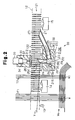
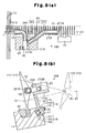
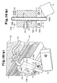
- a jet loom having a weft tensioner is provided with a sley 11 and a deformed reed 12 is vertically arranged and fixed to the sley 11.
- the lower portion of the deformed reed 12 is fastened and fixed by a wedge member 35 in a groove 111 formed on the upper surface of the sley 11.
- a weft guide passage 121 is formed on the front surface of the deformed reed 12.
- a weft Y taken out from a non-illustrated weft-inserting main nozzle flies in the guide passage 121 by the relay jet actions of a plurality of weft inserting auxiliary nozzles 13 (only one in Fig. 1(a) ).
- the weft Y is taken out from a non-illustrated winding-type weft-length-measurement storage apparatus by the air jet action of a weft inserting main nozzle.
- a first weft detector 14 is set between a ground warp T1 for forming a fabric W and a selvage T2 for forming a trimmed selvage W1 and a second weft detector 15 is arranged at the side of the selvage T2.
- Each of the first weft detector 14 and the second weft detector 15 is the reflective photoelectric sensor type and attached to the sley 11.
- the first weft detector 14 and second weft detector 15 respectively have a detection area in the guide passage 121 to detect whether the weft Y arrives in the guide passage 121.
- a weft capturing block 16 is set between the selvage T2 and the second weft detector 15.
- the capturing block 16 is provided with a block body 21 and a support leg 22 connected to the lower portion of the block body 21.
- the capturing block 16 is attached to the sley 11.
- a tilted attaching surface 17 is formed on the front surface of the sley 11.
- a support groove 18 is formed on the attaching surface 17 so as to extend along the longitudinal direction of the sley 11.
- the support groove 18 includes a small width portion 181 at the attaching surface 17 and a large width portion 182 at the back side and a step 183 is formed between the small width portion 181 and the large width portion 182.
- the step 183 extends in parallel with the attaching surface 17.
- the support leg 22 of the capturing block 16 is connected to the attaching surface 17.
- a pair of bolts 19 (refer to Fig. 1(b) ) are inserted into the support leg 22.
- the distal end of a screw portion 191 of each bolt 19 protrudes from the support leg 22 and a lock nut 20 is screwed to the protruded end of the screw portion 191.
- a hexagonal column head portion 192 of each bolt 19 is housed in the large width portion 182 and the maximum diameter of the head portion 192 is larger than the width of the large width portion 182. Therefore, corners of the hexagonal head portion 192 contact the inner wall surface of the large width portion 182 and thereby, the lock nut 20 can be fastened.
- the head portion 192 is pressed against the step 183 because the lock nut 20 is fastened and the support leg 22 (that is, capturing block 16) is fixed to the sley 11.
- the weft-inserting auxiliary nozzle 13 and weft detectors 14 and 15 are attached to the sley 11 by the means same as the means (bolt 19 and lock nut 20) for attaching the capturing block 16 to the sley 11.
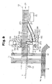
- a groove 23 is formed on an upper surface 211 of the block body 21.
- the groove 23 is opened to a front surface 213 of the block body 21.
- a pair of fit holes 24 and 25 are formed in the block body 21.
- the fit hole 24 is formed so as to reach the groove 23 from a back 212 of the block body 21.
- the fit hole 25 is formed so as to reach the groove 23 from a side 214 (side of the second weft detector 15 side) of the block body 21.
- a first weft capturing pipe 26 is fitted to the fit hole 24 and a second weft capturing pipe 27 is fitted to the fit hole 25.
- a passage 263 in the first capturing pipe 26 extends so as to orthogonally intersect with the direction in which the guide passage 121 extends.
- the protruded end of the first capturing pipe 26 protruded from the fit hole 24 has a diagonally-cut shape and a diagonally-shaped introduction port 261 of the first capturing pipe 26 is caught in the guide passage 121 and faces the selvage T2 side. That is, the introduction port 261 is made to enter the guide passage 121 so as to be connected with the guide passage 121 by facing the direction opposite to the traveling direction of the weft Y.
- the protruded end of the second capturing pipe 27 protruded from the fit hole 25 has a diagonally-cut shape and an diagonally-shaped outlet 271 of the second capturing pipe 27 is caught in the guide passage 121.
- the outlet 271 of the second capturing pipe 27 is faced to the downstream side of the guide passage 121 so as to intersect with the guide passage 121 and the outlet 271 is located upstream of the second weft detector 15 on the guide passage 121.
- an air supply hole 28 is formed on a lower surface 210 of the block body 21 and an air pipe 29 is connected to the air supply hole 28.
- the air pipe 29 is connected to a non-illustrated air pressure supply source through a non-illustrated electromagnetic on-off valve.
- a stretch nozzle 30 is formed on the side wall surface of the block body 21 for forming the groove 23.
- the stretch nozzle 30 is connected to the air supply hole 28, and pressurized air blown into the air supply hole 28 via the air pipe 29 is jetted from the stretch nozzle 30.
- the jet direction of the stretch nozzle 30 aims at an introduction port 272 of the second capturing pipe 27 and the air jetted from the stretch nozzle 30 traverses the groove 23 and is blown into the introduction port 272 of the second capturing pipe 27.
- a curved surface 216 is formed between the back 212 and a side 215 (side at the first weft detector 14) of the block body 21.
- a nozzle forming body 31 is located on the back side of the deformed reed 12.
- a support leg 311 of the nozzle forming body 31 is fastened and fixed by a wedge member 36 in the groove 111.
- a screw 37 passes through the wedge member 36 and screwed to a screw hole 112 at the bottom of the groove 111.
- the wedge member 36 fixes the support leg 311 in the groove 111 by fastening the screw 37.
- a plurality of screw holes 112 are formed along the length direction of the groove 111 and it is possible to select the position of the nozzle forming body 31 in the length direction of the groove 111 by selecting the screw hole 112.
- an air supply hole 32 is formed at the back of the nozzle forming body 31 and an air pipe 33 is connected to the air supply hole 32.
- the air pipe 33 is connected to a non-illustrated air pressure supply source through a non-illustrated electromagnetic on-off valve.
- a buffering plate 34 made of rubber is attached to the front of the nozzle forming body 31.
- a stretch nozzle 312 is formed at the front of the nozzle forming body 31 and a through port 341 is formed on the buffering plate 34.
- a stretch nozzle 312 is connected to the air supply hole 32 and pressurized air blown into the air supply hole 32 via the air pipe 33 is jetted from the stretch nozzle 312.
- the jet direction of the stretch nozzle 312 aims at the introduction port 261 of the first capturing pipe 26.
- the air jetted from the stretch nozzle 312 passes between the through port 341 and a reed wing 122 adjacent to the deformed reed 12, traverses the guide passage 121, and is blown into the introduction port 261 of the first capturing pipe 26.
- Air jet from the stretch nozzles 312 and 30 is started before the leading end of the weft Y reaches the introduction port 261 of the first capturing pipe 26.
- the leading end of the weft Y flown through the guide passage 121 is blown into the first capturing pipe 26 by the air jet from the stretch nozzle 312.
- the leading end of the weft Y blown into the first capturing pipe 26 passes through an outlet 262 of the first capturing pipe 26 and reaches the groove 23.
- the leading end of the weft Y reaching the groove 23 is blown into the introduction port 272 of the second capturing pipe 27 by the air jet from the stretch nozzle 30.
- Stop of air jet from the stretch nozzle 312 is performed after the time when the leading end of the weft Y is regarded as having been blown into the second capturing pipe 27.
- the air jet flow acting on the leading end of the weft Y blown into the second capturing pipe 27 applies a tension to the weft Y.
- the passage 263 and groove 23 in the first capturing pipe 26 and a passage 273 in the second capturing pipe 27 constitute a weft capture passage 38, and the capture passage 38 has a portion extending in a direction intersecting with the direction in which the guide passage 121 extends.
- the capturing block 16, first capturing pipe 26, and second capturing pipe 27 constitute a passage forming body 39 for forming the capture passage 38.
- the first capturing pipe 26 is a cylindrical portion caught in the guide passage 121 so that the introduction port 261 of the capture passage 38 faces the direction opposite to the traveling direction of the weft Y so as to connect with the guide passage 121.
- the groove 23 constituting a part of the capture passage 38 is located in the middle of the capture passage 38 and functions as a branch channel opened to the outside of the passage forming body 39.
- the intersecting portion between the jet direction of the stretch nozzle 312 and the jet direction of the stretch nozzle 30 is located at the connecting portion between the capture passage 38 and the branch channel (groove 23).
- the introduction port 272 functions as a direction change port located at the downstream side of the connecting portion between the branch channel (groove 23) and the capture passage 38.
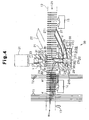
- the weft Y is beaten in a state in which the leading end of the weft Y is bent and captured in the capture passage 38.
- Fig. 4 shows a state in which the weft Y is beaten by the cloth fell Wo of the fabric W.
- the flow rate of an air flow jetted from the stretch nozzle 30 at the introduction port 272 of the second capturing pipe 27 is two times larger than the flow rate of the air flow jetted from the stretch nozzle 312 at the outlet 262 of the first capturing pipe 26.
- the flow rate of the air flow from the stretch nozzle 312 at the introduction port 261 of the first capturing pipe 26 is approximately five times larger than the flow rate of the air flow jetted from the weft-inserting auxiliary nozzle 13 at a position close to the introduction port 261 of the first capturing pipe 26.
- a first weft detector for detecting whether a weft reaches a predetermined position and a second weft detector for detecting whether a weft is inserted longer than a predetermined length are generally used.
- the first weft detector 14 detects the attainment of the weft Y.
- the second weft detector 15 detects the attainment of the weft Y.
- the first weft detector 14 detects whether a weft reaches a predetermined position, and the second weft detector 15 detects whether a weft is inserted longer than a predetermined length.
- the second weft detector 15 detects cases in which the joint of the weft Y or only a cover yarn covering the surface of a stretch yarn is removed.
- a configuration of facing the outlet 271 of the capture passage 38 to the downstream side of the guide passage 121 so that the outlet 271 intersects with the guide passage 121 makes it possible to detect presence or absence of the weft Y in the guide passage 121 by the second weft detector 15.
- a configuration of opening the groove 23 to the upper surface 211 and front surface 213 has an advantage that the flow rate of the air flow jetted from the stretch nozzle 312 is easily attenuated.
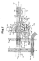
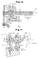
- a fit hole 40 is formed on a block body 21A of a passage forming body 39A.
- a first capturing pipe 26A fitted to the fit hole 40 diagonally intersects with the guide passage 121 so that the direction in which the passage 263 extends faces the downstream side of the guide passage 121.
- a diagonally-shaped introduction port 261A of the first capturing pipe 26A faces the stretch nozzle 312.
- a fit hole 41 is formed on the block body 21A so as to extend toward the side 214 from the groove 23 and a second capturing pipe 27A is fitted to the fit hole 41.
- the jet direction at the stretch nozzle 30 aims at an introduction port 272A of the second capturing pipe 27A and the air jetted from the stretch nozzle 30 traverses the groove 23 and is blown into the introduction port 272A of the second capturing pipe 27A.
- a groove 42 is formed on the upper surface 211 of the block body 21A.
- the groove 42 is opened to the side 214.
- the groove 42 connects with the fit hole 41 in series.
- a fit hole 43 is formed on the block body 21A so as to extend from the back 212 toward the groove 42 and a third capturing pipe 44 is fitted to the fit hole 43.
- a stretch nozzle 45 is formed on the side wall surface of the block body 21A. The jet direction at the stretch nozzle 45 aims at an introduction port 441 of the third capturing pipe 44.
- the stretch nozzle 45 is connected to an air supply hole 46 and the air supply hole 46 is connected to a non-illustrated pressure-air supply source though an air pipe 47 shown in Fig. 6 and a non-illustrated electromagnetic on-off valve.
- the air jetted from the stretch nozzle 45 transverses the groove 42 and is blown into the introduction port 441 of the third capturing pipe 44.
- the portion of the third capturing pipe 44 in the block body 21A is parallel with the first capturing pipe 26A and the end of the third capturing pipe 44 is faced to the downstream side of the guide passage 121 so as to intersect with the guide passage 121 at a shallow angle.
- An outlet 442 of the third capturing pipe 44 is present at the upstream side of the second weft detector 15 with respect to the guide passage 121.
- the passage 263 and groove 23 of the first capturing pipe 26A, passage 273 and groove 42 of the second capturing pipe 27A, and a passage 443 of the third capturing pipe 44 constitute a capture passage 48 and the capture passage 48 has a portion extending in the direction intersecting with the direction in which the guide passage 121 extends.
- the leading end of the weft Y blown into the first capturing pipe 26A by the air flow from the stretch nozzle 312 is blown into the second capturing pipe 27A by the air flow from the stretch nozzle 30.
- the leading end of the weft Y blown into the second capturing pipe 27A is blown into the third capturing pipe 44 by the air flow from the stretch nozzle 45.
- the leading end of the weft Y captured in the capture passage 48 reaches a position close to the end of the third capturing pipe 44.
- the capture passage 48 having more bent portions than those of the capture passage 38 further effectively restrains yarn vibration generated in the weft Y and further improves the tension applying performance. Improvement of the tension applying performance contributes to decrease of air consumption for capturing the weft Y.
- a configuration of diagonally intersecting the first capturing pipe 26A with the guide passage 121 is preferable because the bent angle of a weft at the inner-peripheral margin of the introduction port 261A of the first capturing pipe 26A and that of a weft at the inner-peripheral margin of an outlet 262A of the first capturing pipe 26A become sharp.
- a configuration of opening the groove 42 of the block body 21A to the upper surface 211 and side 214 of the block body 21A has an advantage that the air flow jetted from the stretch nozzle 30 is easily attenuated.
- a first capturing pipe 26B is attached to a block body 21B constituting a passage forming body 39B.
- An introduction port 261B of the first capturing pipe 26B is caught in the guide passage 121 to face the direction (confronting direction) opposite to the traveling direction of the weft Y.
- An outlet 271B of a second capturing pipe 27B of the block body 21B is caught in the guide passage 121 to face the traveling direction of the weft Y.
- the stretch nozzle 30 aims at an introduction port 272B of the second capturing pipe 27B.
- the passage 263 and groove 23 of the first capturing pipe 26B and the passage 273 of the second capturing pipe 27B constitute a capture passage 49 and the capture passage 49 has a portion extending in the direction intersecting with the direction in which the guide passage 121 extends.
- the leading end of the weft Y flown through the guide passage 121 is blown into the first capturing pipe 26B by the air flow from the weft-inserting auxiliary nozzle 13 (refer to Fig. 1(a) ).
- the leading end of the weft Y blown into the first capturing pipe 26B is blown in to the second capturing pipe 27B by the air flow from the stretch nozzle 30.
- An elastic ring 50 made of rubber serving as an elastic material is fitted to the first capturing pipe 26B serving as a cylindrical portion for forming the introduction port 261B of the capture passage 49.
- an elastic ring 51 made of rubber serving as an elastic material is fitted to the second capturing pipe 27B. The elastic rings 50 and 51 contact the wall surface of the reed wing 122 forming the guide passage 121.
- the gap between the outer periphery of the first capturing pipe 26B and the wall surface of the reed wing 122 is closed by the elastic ring 50. Therefore, the leading end of the weft Y is securely introduced into the first capturing pipe 26B. Moreover, because it is prevented by the elastic ring 50 that the reed wing 122 directly contacts the first capturing pipe 26B, abrasion damage due to the vibration of the reed wing 122 at the time of beating is avoided. Abrasion damage is also avoided by the elastic ring 51.
- a capturing block 16C constituting a passage forming body is attached to the first weft detector 14. Because the first weft detector 14 is disposed on the outside of the selvage T2, it is possible to narrow the gap between the ground warp T1 and the selvage T2 compared to the case of the first embodiment. This contributes to decrease of the weft length for one-time weft insertion and decrease of the weft consumption.
- a second capturing pipe 27D attached to a block body 21D constituting a passage forming body 39D orthogonally intersects with the groove 23 and the direction of the second weft detector 15 is opposite to the case of the first embodiment. That is, the detection area of the second weft detector 15 is set on the extension line of the passage 273 of the second capturing pipe 27D.
- the passage 263 and groove 23 of the first capturing pipe 26 and the passage 273 of the second capturing pipe 27D constitute a capture passage 52.
- the jet direction at a stretch nozzle 30E formed at the bottom of the passage 53 aims at an introduction port 272E of the second capturing pipe 27E.
- the leading end of the weft Y introduced into the first capturing pipe 26 is blown into the second capturing pipe 27E by the air flow from the stretch nozzle 30E.
- the passages 263 and 53 of the first capturing pipe 26 and the passage 273 of the second capturing pipe 27E constitute a capture passage 54.
- a capturing block 55 is fastened and joined to the attaching surface 17 of the sley 11 by using a pair of bolts 19 and a pair of nuts 20.
- a pair of fit holes 56 and 57 are formed on the capturing block 55.
- the fit hole 56 is set so as to reach a lower surface 552 of the capturing block 55 from the upper face 551 of the block 55.
- the fit hole 57 is set so as to reach the fit hole 56 from a side 553 (side of the second weft detector 15).
- a first capturing pipe 58 is fitted and fixed to the fit hole 56 and a second capturing pipe 59 is fitted and fixed to the fit hole 57.
- the first capturing pipe 58 is fitted up to the middle of the fit hole 56.
- a protruded portion 581 of the first capturing pipe 58 protruded from the fit hole 56 is curved.
- the end of the protruded portion 581 forms an introduction port 582 having a diagonally-cut shape.
- the introduction port 582 is caught in the guide passage 121 and faces the selvage T2 side. That is, the introduction port 582 is made to enter the guide passage 121 so as to face the direction opposite to the traveling direction of the weft Y and connect with the guide passage 121.
- a passage in the first capturing pipe 58 is constituted of a passage 583 heading for the front of the guide passage 121 (front of the deformed reed 12) from the inside of the guide passage 121 and a downward passage 584 heading downward while heading for the front of the guide passage 121 (front of the deformed reed 12).
- the passage 583 extends in the direction orthogonally intersecting with the direction in which the guide passage 121 extends.
- the protruded end of the second capturing pipe 59 protruded from the fit hole 57 forms an outlet 591 having a diagonally-cut shape.
- the outlet 591 is caught in the guide passage 121.
- the outlet 591 is faced to the downstream side of the guide passage 121 so as to intersect with the guide passage 121 and the outlet 591 is located upstream of the second weft detector 15 for the guide passage 121.
- an air supply hole 60 is formed at a side 554 of the capturing block 55 and the air pipe 29 is connected to the air supply hole 60.
- the air pipe 29 is connected to a non-illustrated air pressure source through a non-illustrated electromagnetic on-off valve.
- a stretch nozzle 61 is formed on the peripheral wall surface of the capturing block 55 for forming the fit hole 56.
- the stretch nozzle 61 is connected with the air supply hole 60 and the pressurized air supplied to the air supply hole 60 via the air pipe 29 is jetted from the stretch nozzle 61.
- the jet direction of the stretch nozzle 61 aims at an introduction port 592 of the second capturing pipe 59 and the air jetted from the stretch nozzle 61 traverses the fit hole 56 and is blown into the introduction port 592 of the second capturing pipe 59.
- the air jet from the stretch nozzles 312 and 61 is started before the leading end of the weft Y reaches the introduction port 582 of the first capturing pipe 58.
- the leading end of the weft Y flown through the guide passage 121 is blown into the first capturing pipe 58 by the air jet from the stretch nozzle 312.
- the leading end of the weft Y blown into the first capturing pipe 58 passes through an outlet 585 of the first capturing pipe 58 and comes on to the fit hole 56.
- the portion below the intersecting portion between the fit holes 56 and 57 is referred to as a branch channel 561.
- the leading end of the weft Y reaching the intersecting portion between the fit holes 56 and 57 is blown into the introduction port 592 of the second capturing pipe 59 by the air jet from the stretch nozzle 61.
- the leading end of the weft Y reaches the middle of the second capturing pipe 59, taking-out of the weft from a weft-length-measurement storage apparatus is prevented.
- the air jet from the stretch nozzle 312 is stopped after the leading end of the weft Y is regarded to be blown into the second capturing pipe 59.
- the air jet flow acting on the leading end of the weft Y blown into the second capturing pipe 59 provides tension for the weft Y.
- the passage 583 and downward passage 584 in the first capturing pipe 58 and a passage 593 in the second capturing pipe 59 constitute a capture passage 62 and the capture passage 62 has a portion extending in the direction intersecting with the direction in which the guide passage 121 extends.
- the capture passage 62 locally includes the downward passage 584 heading downward from the front side of the guide passage 121.
- An outlet 562 (outlet of fit hole 56) of the branch channel 561 connected to the end of the downward passage 584 is opened only downward. That is, the whole of the outlet 562 of the branch channel 561 is seen when vertically viewing it from the bottom.
- the introduction port 592 functions as a direction change port of a capture passage located at the downstream side of the connecting portion between the branch channel 561 and the downward passage 584.
- the capturing block 55, first capturing pipe 58, and second capturing pipe 59 constitute a passage forming body 63 for forming the capture passage 62.
- the first capturing pipe 58 is a cylindrical portion caught in the guide passage 121 so that the introduction port 582 of the capture passage 62 faces the direction opposite to the traveling direction of the weft Y and is connected with the guide passage 121.
- the leading end of the weft Y introduced into the capture passage 62 contact an inner-peripheral margin 586 (illustrated in Fig. 13 ) of the introduction port 582 of the first capturing pipe 58, an inner-peripheral margin 587 (illustrated in Fig. 14(b) ) of the outlet 585, and an inner-peripheral margin 594 (illustrated in Fig. 14(b) ) of the introduction port 592 of the second capturing pipe 59 and is sharply bent.
- the weft Y is beaten while it is captured in a bent shape in the capture passage 62.
- the capture passage 62 includes the passage 583 heading for the front of the guide passage 121 from the introduction port 582 caught in the guide passage 121 and the downward passage 584 heading downward by following the passage 583 as a part of the passage 62. That is, the capture passage 62 has a shape of slightly extending toward the front of the guide passage 121 and then immediately heading downward. In the case of the upper surface of the passage forming body 63 having the capture passage 62 having the above shape, it is possible to decrease the distance protruded to the front from guide passage 121 compared to the case of the upper surface (block body 21) of the passage forming body 39 of, for example, the first embodiment. This is advantageous to avoid the interference with the temple apparatus.
- the branch channel 561 connected to the end of the downward passage 584 plays the same role as the case of the groove 23 of the first embodiment.
- the outlet 562 of the branch channel 561 is located on the lower surface 552 of the capturing block 55. That is, the outlet 562 of the branch channel 561 opened to the outside of the passage forming body 63 is opened only downward and the leading end Ye of a weft constituting the trimmed selvage W1 does not enter the branch channel 561 from the outlet 562.
- a configuration of opening the outlet 562 of the branch channel 561 only downward prevents the leading end Ye of a weft constituting the trimmed selvage W1 from entering the branch channel 561.
- a first capturing pipe 58A is attached to the capturing block 55 constituting a passage forming body 63A and an introduction port 582A of the first capturing pipe 58A enters the guide passage 121 and faces the direction (confronting direction) opposite to the traveling direction of the weft Y.
- a passage 583A and downward passage 584 of the first capturing pipe 58A and the passage 593 of the second capturing pipe 59 constitute a capture passage 64 and the capture passage 64 constitutes the capture passage 64 having a portion extending in the direction intersecting with the direction in which the guide passage 121 extends.
- the leading end of the weft Y flown through the guide passage 121 is blown into the first capturing pipe 58A by the air flow from the weft-inserting auxiliary nozzle 13 (refer to Fig. 1(a) ).
- the leading end of the weft Y blown into the first capturing pipe 58A is blown into the second capturing pipe 59 by the air flow from the stretch nozzle 61.
- An elastic ring 50 made of rubber serving as an elastic material is fitted to the first capturing pipe 58A serving as a cylindrical portion for forming the introduction port 582A of the capture passage 64.
- the elastic ring 50 contacts the wall surface of the reed wing 122 for forming the guide passage 121.
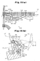
- FIG. 16 (a) and 16(b) A third embodiment according to the invention shown in Figs. 16 (a) and 16(b) will now be described. Same components as those of the first embodiment according to the invention in Figs. 12 to 14(b) are provided with the same reference numerals.
- the fit hole 56 extends through a capturing block 55B constituting a passage forming body 63B and a capturing pipe 58B is fitted and fixed to the fit hole 56.
- the capturing pipe 58B passes through the fit hole 56 and an outlet 585B of the capturing pipe 58B is opened downward at the outside of the capturing block 55B.
- a passage in the capturing pipe 58B is a capture passage 65 constituted of a passage 583B heading for the front (front of the deformed reed 12) of the guide passage 121 from the inside of the guide passage 121 and a downward passage 584B heading downward while heading for the front (front of deformed reed 12) of the guide passage 121.
- the capture passage 65 is opened only to the lower surface of the passage forming body 63B. That is, the whole of the outlet 585B of the capture passage 65 can be vertically seen from the bottom.
- the passage 583B extends in the direction orthogonally intersecting wit the direction in which the guide passage 121 extends similarly to the case of the passage 583 of the first embodiment according to the invention.
- the air supply hole 60 is formed on the side 554 of the capturing block 55B and the air pipe 29 is connected to the air supply hole 60.
- the air pipe 29 is connected to a non-illustrated air pressure supply source through a non-illustrated electromagnetic on-off valve.
- a stretch nozzle 61B is formed on the peripheral wall of the capturing block 55B for forming the fit hole 56 and the peripheral wall of the capturing pipe 58B.
- the stretch nozzle 61B is connected with the air supply hole 60 and pressurized air supplied to the air supply hole 60 via the air pipe 29 is jetted from the stretch nozzle 61B.
- the jet direction of the stretch nozzle 61B aims at the outlet 585B of the capturing pipe 58B and the air jetted from the stretch nozzle 61B heads downward in the downward passage 584B in the capturing pipe 58B.
- the second weft detector 15 has a detection area in the extension area of the outlet 585B of the capturing pipe 58B and detects whether the weft Y reaches the extension area of the outlet 585B. When the weft Y is excessively inserted or cut, the weft Y passes through the detection area of the second weft detector 15.
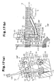
- FIGs. 17 (a) and 17 (B) A seventh embodiment not forming part of the invention in Figs. 17 (a) and 17 (B) will be described below.
- the same reference numerals are used for same components as the case of the first embodiment.
- a branch channel 66 is formed on the block body 21 constituting the capturing block 16 so that the branch channel 66 reaches the fit holes 24 and 25 from the lower surface 210.
- the branch channel 66 constituting a capture passage 38F together with the passages 263 and 273 is opened to the lower surface 210 (that is, lower surface of a passage forming body 39F) of the capturing block 16 constituting the passage forming body 39F.
- the branch channel 66 plays the role similar to the groove 23 of the first embodiment.
- An outlet 651 of the branch channel 66 opened to the outside of the passage forming body 39F is only opened downward. That is, the whole of the outlet 651 of the branch channel 66 can be vertically seen from the bottom.
- the leading end Ye of a weft constituting the trimmed selvage W1 does not enter the branch channel 66 from the outlet 651.
- a configuration of opening the outlet 651 of the branch channel 66 only downward prevents the leading end Ye of a weft constituting the trimmed selvage W1 from entering the branch channel 66.
- the second embodiment it is also allowed to stop the air jet at the stretch nozzles 312 and 30 after the leading end of the weft Y is blown into the third capturing pipe 44.
- the same advantage as the item (1-7) of the first embodiment can be obtained.
- first capturing pipe 26 and second capturing pipe 27 integrally with the block body 21.
- first capturing pipe 26A and second capturing pipe 27A integrally with the block body 21A.
Landscapes
- Engineering & Computer Science (AREA)
- Textile Engineering (AREA)
- Looms (AREA)
Abstract
Priority Applications (1)
| Application Number | Priority Date | Filing Date | Title |
|---|---|---|---|
| EP12004120.7A EP2495360B1 (en) | 2004-02-19 | 2005-02-16 | Weft tensioner of jet loom |
Applications Claiming Priority (3)
| Application Number | Priority Date | Filing Date | Title |
|---|---|---|---|
| JP2004043063 | 2004-02-19 | ||
| JP2004210629A JP4410048B2 (ja) | 2004-02-19 | 2004-07-16 | ジェットルームにおける緯糸張力付与装置 |
| PCT/JP2005/002339 WO2005080651A1 (ja) | 2004-02-19 | 2005-02-16 | ジェットルームにおける緯糸張力付与装置 |
Related Child Applications (2)
| Application Number | Title | Priority Date | Filing Date |
|---|---|---|---|
| EP12004120.7A Division EP2495360B1 (en) | 2004-02-19 | 2005-02-16 | Weft tensioner of jet loom |
| EP12004120.7 Division-Into | 2012-05-29 |
Publications (3)
| Publication Number | Publication Date |
|---|---|
| EP1722019A1 EP1722019A1 (en) | 2006-11-15 |
| EP1722019A4 EP1722019A4 (en) | 2009-08-12 |
| EP1722019B1 true EP1722019B1 (en) | 2012-08-01 |
Family
ID=34889336
Family Applications (2)
| Application Number | Title | Priority Date | Filing Date |
|---|---|---|---|
| EP05719191A Active EP1722019B1 (en) | 2004-02-19 | 2005-02-16 | Weft tension device for jet looms |
| EP12004120.7A Active EP2495360B1 (en) | 2004-02-19 | 2005-02-16 | Weft tensioner of jet loom |
Family Applications After (1)
| Application Number | Title | Priority Date | Filing Date |
|---|---|---|---|
| EP12004120.7A Active EP2495360B1 (en) | 2004-02-19 | 2005-02-16 | Weft tensioner of jet loom |
Country Status (4)
| Country | Link |
|---|---|
| EP (2) | EP1722019B1 (ja) |
| JP (1) | JP4410048B2 (ja) |
| CN (1) | CN1922349B (ja) |
| WO (1) | WO2005080651A1 (ja) |
Cited By (1)
| Publication number | Priority date | Publication date | Assignee | Title |
|---|---|---|---|---|
| EP4261332A1 (en) * | 2022-04-13 | 2023-10-18 | Kabushiki Kaisha Toyota Jidoshokki | Air jet loom with weft yarn tensioning device |
Families Citing this family (9)
| Publication number | Priority date | Publication date | Assignee | Title |
|---|---|---|---|---|
| EP1897981A1 (de) * | 2006-09-07 | 2008-03-12 | Sultex AG | Verfahren und Streckvorrichtung zum Halten eines Schussfadens |
| BE1017893A5 (nl) * | 2007-12-10 | 2009-10-06 | Te Strake Textile Bv | Strekinrichting voor het strekken van een inslagdraad. |
| KR101031270B1 (ko) | 2009-02-26 | 2011-04-29 | (재)한국섬유기계연구소 | 에어제트 직기의 얀 스트레치 시스템 |
| JP5365268B2 (ja) * | 2009-03-06 | 2013-12-11 | 株式会社豊田自動織機 | ジェットルームにおける緯糸検出装置 |
| JP5369915B2 (ja) * | 2009-06-11 | 2013-12-18 | 株式会社豊田自動織機 | エアジェット織機における緯糸張力付与装置 |
| BE1019614A3 (nl) | 2009-07-01 | 2012-09-04 | Picanol | Inrichting en werkwijze voor het vangen en strekken van inslagdraden bij weefmachines. |
| EP2348144A1 (en) * | 2010-01-26 | 2011-07-27 | ITEMA (Switzerland) Ltd. | Pneumatic stretching device of the weft thread for air-jet weaving looms, with a weft deflecting head arranged inside the launch channel of the reed |
| JP6119715B2 (ja) * | 2014-10-27 | 2017-04-26 | 株式会社豊田自動織機 | エアジェット織機における緯糸張力付与装置 |
| JP2022014545A (ja) * | 2020-07-07 | 2022-01-20 | 株式会社豊田自動織機 | 緯糸張力付与装置 |
Family Cites Families (11)
| Publication number | Priority date | Publication date | Assignee | Title |
|---|---|---|---|---|
| GB1365903A (en) * | 1970-08-07 | 1974-09-04 | Teijin Ltd | Method of and apparatus for controlling weft tension in a jet loom |
| NL7206367A (ja) | 1972-05-10 | 1973-11-13 | ||
| NL7605882A (nl) | 1976-05-31 | 1977-12-02 | Rueti Te Strake Bv | Weefmachine. |
| JPS6063580U (ja) * | 1983-10-04 | 1985-05-04 | 津田駒工業株式会社 | 無杼織機における緯糸緊張装置 |
| JPS61147287U (ja) * | 1985-02-28 | 1986-09-11 | ||
| JPS61147286U (ja) * | 1985-03-01 | 1986-09-11 | ||
| JPH0444634Y2 (ja) * | 1986-04-15 | 1992-10-21 | ||
| JPH0643188Y2 (ja) * | 1989-02-28 | 1994-11-09 | 津田駒工業株式会社 | 織機の緯糸緊張装置 |
| BE1006073A3 (nl) * | 1992-07-03 | 1994-05-03 | Picanol Nv | Inslagwachter voor weefmachines. |
| JPH07279001A (ja) * | 1994-03-31 | 1995-10-24 | Toyota Autom Loom Works Ltd | ジェットルームにおける緯糸張力付与装置 |
| JP4057086B2 (ja) | 1997-01-14 | 2008-03-05 | 株式会社豊田自動織機 | ジェットルームにおける緯糸張力付与装置 |
-
2004
- 2004-07-16 JP JP2004210629A patent/JP4410048B2/ja active Active
-
2005
- 2005-02-16 EP EP05719191A patent/EP1722019B1/en active Active
- 2005-02-16 CN CN200580005346XA patent/CN1922349B/zh active Active
- 2005-02-16 EP EP12004120.7A patent/EP2495360B1/en active Active
- 2005-02-16 WO PCT/JP2005/002339 patent/WO2005080651A1/ja active Application Filing
Cited By (1)
| Publication number | Priority date | Publication date | Assignee | Title |
|---|---|---|---|---|
| EP4261332A1 (en) * | 2022-04-13 | 2023-10-18 | Kabushiki Kaisha Toyota Jidoshokki | Air jet loom with weft yarn tensioning device |
Also Published As
| Publication number | Publication date |
|---|---|
| JP4410048B2 (ja) | 2010-02-03 |
| EP2495360B1 (en) | 2013-07-24 |
| WO2005080651A1 (ja) | 2005-09-01 |
| CN1922349B (zh) | 2011-11-16 |
| EP2495360A1 (en) | 2012-09-05 |
| EP1722019A4 (en) | 2009-08-12 |
| EP1722019A1 (en) | 2006-11-15 |
| CN1922349A (zh) | 2007-02-28 |
| JP2005264416A (ja) | 2005-09-29 |
Similar Documents
| Publication | Publication Date | Title |
|---|---|---|
| EP1722019B1 (en) | Weft tension device for jet looms | |
| CN102094283B (zh) | 橡胶加强用织物编织用织机中的织入边形成装置 | |
| JP3276652B2 (ja) | 織機におけるよこ糸の引張り装置 | |
| US20080271807A1 (en) | Method and a stretching device for the holding of a weft thread | |
| CN106460260B (zh) | 用于纬纱的拉伸装置 | |
| JP3405962B2 (ja) | 分割筬 | |
| CN113913999B (zh) | 纬纱张力赋予装置 | |
| EP2808431B1 (en) | Air jet loom part with weft yarn tension applying apparatus, air jet loom and method of using the air jet loom part | |
| JP2002061052A (ja) | タックイン装置 | |
| JP2023156763A (ja) | エアジェット織機の緯糸張力付与装置 | |
| WO2011092085A1 (en) | Pneumatic stretching device of the weft thread for air-jet weaving looms, with a weft deflecting head arranged inside the launch channel of the reed | |
| US20080178959A1 (en) | Catching apparatus and method for a rapier weaving machine | |
| JP2829704B2 (ja) | 流体噴射織機の緯糸安定化装置 | |
| JP3405950B2 (ja) | エアージェット織機の緯糸案内装置 | |
| JPH0426463Y2 (ja) | ||
| JPH0643188Y2 (ja) | 織機の緯糸緊張装置 | |
| JP4909880B2 (ja) | エアジェットルームにおける筬 | |
| JP2759511B2 (ja) | 複数幅取り織機のセンタ・タックイン部におけるウェフト過張力緩和装置 | |
| JPH0315578Y2 (ja) | ||
| JPH09137339A (ja) | エアジェットルームの開口補助装置 | |
| JP3313510B2 (ja) | 無杼織機の房耳処理装置 | |
| JPH0449188Y2 (ja) | ||
| CZ269095A3 (en) | Open weft picking channel | |
| JPH0346575B2 (ja) | ||
| JPH09195144A (ja) | 織機における房耳規制装置 |
Legal Events
| Date | Code | Title | Description |
|---|---|---|---|
| PUAI | Public reference made under article 153(3) epc to a published international application that has entered the european phase |
Free format text: ORIGINAL CODE: 0009012 |
|
| 17P | Request for examination filed |
Effective date: 20060830 |
|
| AK | Designated contracting states |
Kind code of ref document: A1 Designated state(s): BE |
|
| DAX | Request for extension of the european patent (deleted) | ||
| RBV | Designated contracting states (corrected) |
Designated state(s): BE |
|
| A4 | Supplementary search report drawn up and despatched |
Effective date: 20090709 |
|
| 17Q | First examination report despatched |
Effective date: 20100720 |
|
| GRAP | Despatch of communication of intention to grant a patent |
Free format text: ORIGINAL CODE: EPIDOSNIGR1 |
|
| GRAS | Grant fee paid |
Free format text: ORIGINAL CODE: EPIDOSNIGR3 |
|
| GRAA | (expected) grant |
Free format text: ORIGINAL CODE: 0009210 |
|
| AK | Designated contracting states |
Kind code of ref document: B1 Designated state(s): BE |
|
| PLBE | No opposition filed within time limit |
Free format text: ORIGINAL CODE: 0009261 |
|
| STAA | Information on the status of an ep patent application or granted ep patent |
Free format text: STATUS: NO OPPOSITION FILED WITHIN TIME LIMIT |
|
| 26N | No opposition filed |
Effective date: 20130503 |
|
| PGFP | Annual fee paid to national office [announced via postgrant information from national office to epo] |
Ref country code: BE Payment date: 20230117 Year of fee payment: 19 |
|
| P01 | Opt-out of the competence of the unified patent court (upc) registered |
Effective date: 20230519 |