EP1722019A1 - Weft tension device for jet looms - Google Patents
Weft tension device for jet looms Download PDFInfo
- Publication number
- EP1722019A1 EP1722019A1 EP05719191A EP05719191A EP1722019A1 EP 1722019 A1 EP1722019 A1 EP 1722019A1 EP 05719191 A EP05719191 A EP 05719191A EP 05719191 A EP05719191 A EP 05719191A EP 1722019 A1 EP1722019 A1 EP 1722019A1
- Authority
- EP
- European Patent Office
- Prior art keywords
- passage
- weft
- capture
- forming body
- stretch nozzle
- Prior art date
- Legal status (The legal status is an assumption and is not a legal conclusion. Google has not performed a legal analysis and makes no representation as to the accuracy of the status listed.)
- Granted
Links
Images


Classifications
-
- D—TEXTILES; PAPER
- D03—WEAVING
- D03D—WOVEN FABRICS; METHODS OF WEAVING; LOOMS
- D03D47/00—Looms in which bulk supply of weft does not pass through shed, e.g. shuttleless looms, gripper shuttle looms, dummy shuttle looms
- D03D47/28—Looms in which bulk supply of weft does not pass through shed, e.g. shuttleless looms, gripper shuttle looms, dummy shuttle looms wherein the weft itself is projected into the shed
- D03D47/30—Looms in which bulk supply of weft does not pass through shed, e.g. shuttleless looms, gripper shuttle looms, dummy shuttle looms wherein the weft itself is projected into the shed by gas jet
- D03D47/3066—Control or handling of the weft at or after arrival
- D03D47/308—Stretching or holding the weft
Definitions
- the present invention relates to a jet loom for inserting a weft along a guide passage by the air jet action of a weft-inserting nozzle, particularly to a jet loom provided with a weft tensioner for introducing the weft into a capture passage by an air flow jetted from a stretch nozzle and capturing the weft.
- a jet loom takes out a weft from a weft-length-measurement storage apparatus by the air jet action of a weft-inserting nozzle. Taking-out of a weft from the weft-length-measurement storage apparatus is controlled so as to insert a weft having a length for one time of weft insertion. That is, the weft-length-measurement storage apparatus is changed to a state capable of taking out a weft and a state not capable of taking out a weft.
- a weft having a length for one-time weft insertion is inserted.
- a tension wave heading for the leading end of a weft from the weft-length-measurement storage apparatus is generated in a flying weft. The tension wave reaches the leading end of the weft and then returns to the direction opposite to the traveling direction of the weft.
- weft tension differs at the right and left of fabric and the fabric quality is deteriorated.
- Weft tensioners for solving the above problem are disclosed in Patent Documents 1 to 5.
- the weft tensioners respectively provide a proper tension to an inserted weft at the time of beating.
- the weft tensioners disclosed in Patent Documents 1 and 2 are respectively set on a side of the sley or loom corresponding to the weft-insertion terminal.
- air is blown into a pipe from a nozzle so as to traverse a weft guide passage and the leading end of a weft flown through the guide passage is introduced into the pipe from the nozzle.
- the leading end of the weft is bent due to an air flow and captured in the pipe and tension is applied to the weft.
- a nozzle is located on the front side of a reed and a capturing pipe is located on the back of the reed.
- the air jetted from the nozzle transverses the weft guide passage at the front of the reed and blown into the capturing pipe and the leading end of a weft flown through the guide passage is introduced into the capturing pipe due to supply of the air.
- the leading end of the weft is bent by air flow and captured in the capturing pipe, and tension is applied to the weft.
- an air blower is built in a weft guide passage formed at the front side of a reed.
- the leading end of a weft flown through the guide passage enters the air blower to receive the action of an air flow.
- the present invention can correspond to a change of weaving widths without deteriorating the weaving quality and moreover, it is an object of the present invention to provide a weft tensioner which can provide a sufficient tension for a weft.
- the present invention provides a weft tensioner having a passage forming body for forming a capture passage and a stretch nozzle to introduce a weft into the capture passage by an air flow jetted from the stretch nozzle in order to capture the weft in the capture passage.
- the passage forming body is located on the front side of the guide passage and it is possible to change the position of the passage forming body along the guide passage. At least a part of the capture passage extends in the direction intersecting with the direction along which the guide passage extends.
- the leading end of the weft introduced into the capture passage is captured by the capture passage while it is bent.
- a configuration for capturing the leading end of the weft while it is bent by an air flow provides a sufficient tension for the weft.
- the passage forming body having the capture passage it is unnecessary to increase the gap between reed wings like a conventional device for passing a weft between adjacent reed wings and introducing the weft into a capturing pipe. Therefore, a fabric is not damaged due to increase of the reed-wing interval.
- it is possible to change the position of the passage forming body it is possible to correspond to the change of a weaving width.
- a jet loom having a weft tensioner is provided with a sley 11 and a deformed reed 12 is vertically arranged and fixed to the sley 11.
- the lower portion of the deformed reed 12 is fastened and fixed by a wedge member 35 in a groove 111 formed on the upper surface of the sley 11.
- a weft guide passage 121 is formed on the front surface of the deformed reed 12.
- a weft Y taken out from a non-illustrated weft-inserting main nozzle flies in the guide passage 121 by the relay jet actions of a plurality of weft inserting auxiliary nozzles 13 (only one in Fig. 1(a)).
- the weft Y is taken out from a non-illustrated winding-type weft-length-measurement storage apparatus by the air jet action of a weft inserting main nozzle.
- a first weft detector 14 is set between a ground warp T1 for forming a fabric W and a selvage T2 for forming a trimmed selvage W1 and a second weft detector 15 is arranged at the side of the selvage T2.
- Each of the first weft detector 14 and the second weft detector 15 is the reflective photoelectric sensor type and attached to the sley 11.
- the first weft detector 14 and second weft detector 15 respectively have a detection area in the guide passage 121 to detect whether the weft Y arrives in the guide passage 121.
- a weft capturing block 16 is set between the selvage T2 and the second weft detector 15.
- the capturing block 16 is provided with a block body 21 and a support leg 22 connected to the lower portion of the block body 21.
- the capturing block 16 is attached to the sley 11.
- a tilted attaching surface 17 is formed on the front surface of the sley 11.
- a support groove 18 is formed on the attaching surface 17 so as to extend along the longitudinal direction of the sley 11.
- the support groove 18 includes a small width portion 181 at the attaching surface 17 and a large width portion 182 at the back side and a step 183 is formed between the small width portion 181 and the large width portion 182.
- the step 183 extends in parallel with the attaching surface 17.
- the support leg 22 of the capturing block 16 is connected to the attaching surface 17.
- a pair of bolts 19 (refer to Fig. 1(b)) are inserted into the support leg 22.
- the distal end of a screw portion 191 of each bolt 19 protrudes from the support leg 22 and a lock nut 20 is screwed to the protruded end of the screw portion 191.
- a hexagonal column head portion 192 of each bolt 19 is housed in the large width portion 182 and the maximum diameter of the head portion 192 is larger than the width of the large width portion 182. Therefore, corners of the hexagonal head portion 192 contact the inner wall surface of the large width portion 182 and thereby, the lock nut 20 can be fastened.
- the head portion 192 is pressed against the step 183 because the lock nut 20 is fastened and the support leg 22 (that is, capturing block 16) is fixed to the sley 11.
- the weft-inserting auxiliary nozzle 13 and weft detectors 14 and 15 are attached to the sley 11 by the means same as the means (bolt 19 and lock nut 20) for attaching the capturing block 16 to the sley 11.
- a groove 23 is formed on an upper surface 211 of the block body 21.
- the groove 23 is opened to a front surface 213 of the block body 21.
- a pair of fit holes 24 and 25 are formed in the block body 21.
- the fit hole 24 is formed so as to reach the groove 23 from a back 212 of the block body 21.
- the fit hole 25 is formed so as to reach the groove 23 from a side 214 (side of the second weft detector 15 side) of the block body 21.
- a first weft capturing pipe 26 is fitted to the fit hole 24 and a second weft capturing pipe 27 is fitted to the fit hole 25.
- a passage 263 in the first capturing pipe 26 extends so as to orthogonally intersect with the direction in which the guide passage 121 extends.
- the protruded end of the first capturing pipe 26 protruded from the fit hole 24 has a diagonally-cut shape and a diagonally-shaped introduction port 261 of the first capturing pipe 26 is caught in the guide passage 121 and faces the selvage T2 side. That is, the introduction port 261 is made to enter the guide passage 121 so as to be connected with the guide passage 121 by facing the direction opposite to the traveling direction of the weft Y.
- the protruded end of the second capturing pipe 27 protruded from the fit hole 25 has a diagonally-cut shape and an diagonally-shaped outlet 271 of the second capturing pipe 27 is caught in the guide passage 121.
- the outlet 271 of the second capturing pipe 27 is faced to the downstream side of the guide passage 121 so as to intersect with the guide passage 121 and the outlet 271 is located upstream of the second weft detector 15 on the guide passage 121.
- an air supply hole 28 is formed on a lower surface 210 of the block body 21 and an air pipe 29 is connected to the air supply hole 28.
- the air pipe 29 is connected to a non-illustrated air pressure supply source through a non-illustrated electromagnetic on-off valve.
- a stretch nozzle 30 is formed on the side wall surface of the block body 21 for forming the groove 23.
- the stretch nozzle 30 is connected to the air supply hole 28, and pressurized air blown into the air supply hole 28 via the air pipe 29 is jetted from the stretch nozzle 30.
- the jet direction of the stretch nozzle 30 aims at an introduction port 272 of the second capturing pipe 27 and the air jetted from the stretch nozzle 30 traverses the groove 23 and is blown into the introduction port 272 of the second capturing pipe 27.
- a curved surface 216 is formed between the back 212 and a side 215 (side at the first weft detector 14) of the block body 21.
- a nozzle forming body 31 is located on the back side of the deformed reed 12.
- a support leg 311 of the nozzle forming body 31 is fastened and fixed by a wedge member 36 in the groove 111.
- a screw 37 passes through the wedge member 36 and screwed to a screw hole 112 at the bottom of the groove 111.
- the wedge member 36 fixes the support leg 311 in the groove 111 by fastening the screw 37.
- a plurality of screw holes 112 are formed along the length direction of the groove 111 and it is possible to select the position of the nozzle forming body 31 in the length direction of the groove 111 by selecting the screw hole 112.
- an air supply hole 32 is formed at the back of the nozzle forming body 31 and an air pipe 33 is connected to the air supply hole 32.
- the air pipe 33 is connected to a non-illustrated air pressure supply source through a non-illustrated electromagnetic on-off valve.
- a buffering plate 34 made of rubber is attached to the front of the nozzle forming body 31.
- a stretch nozzle 312 is formed at the front of the nozzle forming body 31 and a through port 341 is formed on the buffering plate 34.
- a stretch nozzle 312 is connected to the air supply hole 32 and pressurized air blown into the air supply hole 32 via the air pipe 33 is jetted from the stretch nozzle 312.
- the jet direction of the stretch nozzle 312 aims at the introduction port 261 of the first capturing pipe 26.
- the air jetted from the stretch nozzle 312 passes between the through port 341 and a reed wing 122 adjacent to the deformed reed 12, traverses the guide passage 121, and is blown into the introduction port 261 of the first capturing pipe 26.
- Air jet from the stretch nozzles 312 and 30 is started before the leading end of the weft Y reaches the introduction port 261 of the first capturing pipe 26.
- the leading end of the weft Y flown through the guide passage 121 is blown into the first capturing pipe 26 by the air jet from the stretch nozzle 312.
- the leading end of the weft Y blown into the first capturing pipe 26 passes through an outlet 262 of the first capturing pipe 26 and reaches the groove 23.
- the leading end of the weft Y reaching the groove 23 is blown into the introduction port 272 of the second capturing pipe 27 by the air jet from the stretch nozzle 30.
- Stop of air jet from the stretch nozzle 312 is performed after the time when the leading end of the weft Y is regarded as having been blown into the second capturing pipe 27.
- the air jet flow acting on the leading end of the weft Y blown into the second capturing pipe 27 applies a tension to the weft Y.
- the passage 263 and groove 23 in the first capturing pipe 26 and a passage 273 in the second capturing pipe 27 constitute a weft capture passage 38, and the capture passage 38 has a portion extending in a direction intersecting with the direction in which the guide passage 121 extends.
- the capturing block 16, first capturing pipe 26, and second capturing pipe 27 constitute a passage forming body 39 for forming the capture passage 38.
- the first capturing pipe 26 is a cylindrical portion caught in the guide passage 121 so that the introduction port 261 of the capture passage 38 faces the direction opposite to the traveling direction of the weft Y so as to connect with the guide passage 121.
- the groove 23 constituting a part of the capture passage 38 is located in the middle of the capture passage 38 and functions as a branch channel opened to the outside of the passage forming body 39.
- the intersecting portion between the jet direction of the stretch nozzle 312 and the jet direction of the stretch nozzle 30 is located at the connecting portion between the capture passage 38 and the branch channel (groove 23).
- the introduction port 272 functions as a direction change port located at the downstream side of the connecting portion between the branch channel (groove 23) and the capture passage 38.
- the weft Y is beaten in a state in which the leading end of the weft Y is bent and captured in the capture passage 38.
- Fig. 4 shows a state in which the weft Y is beaten by the cloth fell Wo of the fabric W.
- the flow rate of an air flow jetted from the stretch nozzle 30 at the introduction port 272 of the second capturing pipe 27 is two times larger than the flow rate of the air flow jetted from the stretch nozzle 312 at the outlet 262 of the first capturing pipe 26.
- the flow rate of the air flow from the stretch nozzle 312 at the introduction port 261 of the first capturing pipe 26 is approximately five times larger than the flow rate of the air flow jetted from the weft-inserting auxiliary nozzle 13 at a position close to the introduction port 261 of the first capturing pipe 26.
- a first weft detector for detecting whether a weft reaches a predetermined position and a second weft detector for detecting whether a weft is inserted longer than a predetermined length are generally used.
- the first weft detector 14 detects the attainment of the weft Y.
- the second weft detector 15 detects the attainment of the weft Y.
- the first weft detector 14 detects whether a weft reaches a predetermined position, and the second weft detector 15 detects whether a weft is inserted longer than a predetermined length.
- the second weft detector 15 detects cases in which the joint of the weft Y or only a cover yarn covering the surface of a stretch yarn is removed.
- a configuration of facing the outlet 271 of the capture passage 38 to the downstream side of the guide passage 121 so that the outlet 271 intersects with the guide passage 121 makes it possible to detect presence or absence of the weft Y in the guide passage 121 by the second weft detector 15.
- a configuration of opening the groove 23 to the upper surface 211 and front surface 213 has an advantage that the flow rate of the air flow jetted from the stretch nozzle 312 is easily attenuated.
- a fit hole 40 is formed on a block body 21A of a passage forming body 39A.
- a first capturing pipe 26A fitted to the fit hole 40 diagonally intersects with the guide passage 121 so that the direction in which the passage 263 extends faces the downstream side of the guide passage 121.
- a diagonally-shaped introduction port 261A of the first capturing pipe 26A faces the stretch nozzle 312.
- a fit hole 41 is formed on the block body 21A so as to extend toward the side 214 from the groove 23 and a second capturing pipe 27A is fitted to the fit hole 41.
- the jet direction at the stretch nozzle 30 aims at an introduction port 272A of the second capturing pipe 27A and the air jetted from the stretch nozzle 30 traverses the groove 23 and is blown into the introduction port 272A of the second capturing pipe 27A.
- a groove 42 is formed on the upper surface 211 of the block body 21A.
- the groove 42 is opened to the side 214.
- the groove 42 connects with the fit hole 41 in series.
- a fit hole 43 is formed on the block body 21A so as to extend from the back 212 toward the groove 42 and a third capturing pipe 44 is fitted to the fit hole 43.
- a stretch nozzle 45 is formed on the side wall surface of the block body 21A. The jet direction at the stretch nozzle 45 aims at an introduction port 441 of the third capturing pipe 44.
- the stretch nozzle 45 is connected to an air supply hole 46 and the air supply hole 46 is connected to a non-illustrated pressure-air supply source though an air pipe 47 shown in Fig. 6 and a non-illustrated electromagnetic on-off valve.
- the air jetted from the stretch nozzle 45 transverses the groove 42 and is blown into the introduction port 441 of the third capturing pipe 44.
- the portion of the third capturing pipe 44 in the block body 21A is parallel with the first capturing pipe 26A and the end of the third capturing pipe 44 is faced to the downstream side of the guide passage 121 so as to intersect with the guide passage 121 at a shallow angle.
- An outlet 442 of the third capturing pipe 44 is present at the upstream side of the second weft detector 15 with respect to the guide passage 121.
- the passage 263 and groove 23 of the first capturing pipe 26A, passage 273 and groove 42 of the second capturing pipe 27A, and a passage 443 of the third capturing pipe 44 constitute a capture passage 48 and the capture passage 48 has a portion extending in the direction intersecting with the direction in which the guide passage 121 extends.
- the leading end of the weft Y blown into the first capturing pipe 26A by the air flow from the stretch nozzle 312 is blown into the second capturing pipe 27A by the air flow from the stretch nozzle 30.
- the leading end of the weft Y blown into the second capturing pipe 27A is blown into the third capturing pipe 44 by the air flow from the stretch nozzle 45.
- the leading end of the weft Y captured in the capture passage 48 reaches a position close to the end of the third capturing pipe 44.
- the capture passage 48 having more bent portions than those of the capture passage 38 further effectively restrains yarn vibration generated in the weft Y and further improves the tension applying performance. Improvement of the tension applying performance contributes to decrease of air consumption for capturing the weft Y.
- a configuration of diagonally intersecting the first capturing pipe 26A with the guide passage 121 is preferable because the bent angle of a weft at the inner-peripheral margin of the introduction port 261A of the first capturing pipe 26A and that of a weft at the inner-peripheral margin of an outlet 262A of the first capturing pipe 26A become sharp.
- a configuration of opening the groove 42 of the block body 21A to the upper surface 211 and side 214 of the block body 21A has an advantage that the air flow jetted from the stretch nozzle 30 is easily attenuated.
- a first capturing pipe 26B is attached to a block body 21B constituting a passage forming body 39B.
- An introduction port 261B of the first capturing pipe 26B is caught in the guide passage 121 to face the direction (confronting direction) opposite to the traveling direction of the weft Y.
- An outlet 271B of a second capturing pipe 27B of the block body 21B is caught in the guide passage 121 to face the traveling direction of the weft Y.
- the stretch nozzle 30 aims at an introduction port 272B of the second capturing pipe 27B.
- the passage 263 and groove 23 of the first capturing pipe 26B and the passage 273 of the second capturing pipe 27B constitute a capture passage 49 and the capture passage 49 has a portion extending in the direction intersecting with the direction in which the guide passage 121 extends.
- the leading end of the weft Y flown through the guide passage 121 is blown into the first capturing pipe 26B by the air flow from the weft-inserting auxiliary nozzle 13 (refer to Fig. 1(a)).
- the leading end of the weft Y blown into the first capturing pipe 26B is blown in to the second capturing pipe 27B by the air flow from the stretch nozzle 30.
- An elastic ring 50 made of rubber serving as an elastic material is fitted to the first capturing pipe 26B serving as a cylindrical portion for forming the introduction port 261B of the capture passage 49.
- an elastic ring 51 made of rubber serving as an elastic material is fitted to the second capturing pipe 27B. The elastic rings 50 and 51 contact the wall surface of the reed wing 122 forming the guide passage 121.
- the gap between the outer periphery of the first capturing pipe 26B and the wall surface of the reed wing 122 is closed by the elastic ring 50. Therefore, the leading end of the weft Y is securely introduced into the first capturing pipe 26B. Moreover, because it is prevented by the elastic ring 50 that the reed wing 122 directly contacts the first capturing pipe 26B, abrasion damage due to the vibration of the reed wing 122 at the time of beating is avoided. Abrasion damage is also avoided by the elastic ring 51.
- the present invention may be applied as fourth, fifth, and sixth embodiments shown in Figs. 9, 10, and 11.
- same components as the case of the first embodiment use the same reference numerals.
- a capturing block 16C constituting a passage forming body is attached to the first weft detector 14. Because the first weft detector 14 is disposed on the outside of the selvage T2, it is possible to narrow the gap between the ground warp T1 and the selvage T2 compared to the case of the first embodiment. This contributes to decrease of the weft length for one-time weft insertion and decrease of the weft consumption.
- a second capturing pipe 27D attached to a block body 21D constituting a passage forming body 39D orthogonally intersects with the groove 23 and the direction of the second weft detector 15 is opposite to the case of the first embodiment. That is, the detection area of the second weft detector 15 is set on the extension line of the passage 273 of the second capturing pipe 27D.
- the passage 263 and groove 23 of the first capturing pipe 26 and the passage 273 of the second capturing pipe 27D constitute a capture passage 52.
- the jet direction at a stretch nozzle 30E formed at the bottom of the passage 53 aims at an introduction port 272E of the second capturing pipe 27E.
- the leading end of the weft Y introduced into the first capturing pipe 26 is blown into the second capturing pipe 27E by the air flow from the stretch nozzle 30E.
- the passages 263 and 53 of the first capturing pipe 26 and the passage 273 of the second capturing pipe 27E constitute a capture passage 54.
- a capturing block 55 is fastened and joined to the attaching surface 17 of the sley 11 by using a pair of bolts 19 and a pair of nuts 20.
- a pair of fit holes 56 and 57 are formed on the capturing block 55.
- the fit hole 56 is set so as to reach a lower surface 552 of the capturing block 55 from the upper face 551 of the block 55.
- the fit hole 57 is set so as to reach the fit hole 56 from a side 553 (side of the second weft detector 15).
- a first capturing pipe 58 is fitted and fixed to the fit hole 56 and a second capturing pipe 59 is fitted and fixed to the fit hole 57.
- the first capturing pipe 58 is fitted up to the middle of the fit hole 56.
- a protruded portion 581 of the first capturing pipe 58 protruded from the fit hole 56 is curved.
- the end of the protruded portion 581 forms an introduction port 582 having a diagonally-cut shape.
- the introduction port 582 is caught in the guide passage 121 and faces the selvage T2 side. That is, the introduction port 582 is made to enter the guide passage 121 so as to face the direction opposite to the traveling direction of the weft Y and connect with the guide passage 121.
- a passage in the first capturing pipe 58 is constituted of a passage 583 heading for the front of the guide passage 121 (front of the deformed reed 12) from the inside of the guide passage 121 and a downward passage 584 heading downward while heading for the front of the guide passage 121 (front of the deformed reed 12).
- the passage 583 extends in the direction orthogonally intersecting with the direction in which the guide passage 121 extends.
- the protruded end of the second capturing pipe 59 protruded from the fit hole 57 forms an outlet 591 having a diagonally-cut shape.
- the outlet 591 is caught in the guide passage 121.
- the outlet 591 is faced to the downstream side of the guide passage 121 so as to intersect with the guide passage 121 and the outlet 591 is located upstream of the second weft detector 15 for the guide passage 121.
- an air supply hole 60 is formed at a side 554 of the capturing block 55 and the air pipe 29 is connected to the air supply hole 60.
- the air pipe 29 is connected to a non-illustrated air pressure source through a non-illustrated electromagnetic on-off valve.
- a stretch nozzle 61 is formed on the peripheral wall surface of the capturing block 55 for forming the fit hole 56.
- the stretch nozzle 61 is connected with the air supply hole 60 and the pressurized air supplied to the air supply hole 60 via the air pipe 29 is jetted from the stretch nozzle 61.
- the jet direction of the stretch nozzle 61 aims at an introduction port 592 of the second capturing pipe 59 and the air jetted from the stretch nozzle 61 traverses the fit hole 56 and is blown into the introduction port 592 of the second capturing pipe 59.
- the air jet from the stretch nozzles 312 and 61 is started before the leading end of the weft Y reaches the introduction port 582 of the first capturing pipe 58.
- the leading end of the weft Y flown through the guide passage 121 is blown into the first capturing pipe 58 by the air jet from the stretch nozzle 312.
- the leading end of the weft Y blown into the first capturing pipe 58 passes through an outlet 585 of the first capturing pipe 58 and comes on to the fit hole 56.
- the portion below the intersecting portion between the fit holes 56 and 57 is referred to as a branch channel 561.
- the leading end of the weft Y reaching the intersecting portion between the fit holes 56 and 57 is blown into the introduction port 592 of the second capturing pipe 59 by the air jet from the stretch nozzle 61.
- the leading end of the weft Y reaches the middle of the second capturing pipe 59, taking-out of the weft from a weft-length-measurement storage apparatus is prevented.
- the air jet from the stretch nozzle 312 is stopped after the leading end of the weft Y is regarded to be blown into the second capturing pipe 59.
- the air jet flow acting on the leading end of the weft Y blown into the second capturing pipe 59 provides tension for the weft Y.
- the passage 583 and downward passage 584 in the first capturing pipe 58 and a passage 593 in the second capturing pipe 59 constitute a capture passage 62 and the capture passage 62 has a portion extending in the direction intersecting with the direction in which the guide passage 121 extends.
- the capture passage 62 locally includes the downward passage 584 heading downward from the front side of the guide passage 121.
- An outlet 562 (outlet of fit hole 56) of the branch channel 561 connected to the end of the downward passage 584 is opened only downward. That is, the whole of the outlet 562 of the branch channel 561 is seen when vertically viewing it from the bottom.
- the introduction port 592 functions as a direction change port of a capture passage located at the downstream side of the connecting portion between the branch channel 561 and the downward passage 584.
- the capturing block 55, first capturing pipe 58, and second capturing pipe 59 constitute a passage forming body 63 for forming the capture passage 62.
- the first capturing pipe 58 is a cylindrical portion caught in the guide passage 121 so that the introduction port 582 of the capture passage 62 faces the direction opposite to the traveling direction of the weft Y and is connected with the guide passage 121.
- the leading end of the weft Y introduced into the capture passage 62 contact an inner-peripheral margin 586 (illustrated in Fig. 13) of the introduction port 582 of the first capturing pipe 58, an inner-peripheral margin 587 (illustrated in Fig. 14(b)) of the outlet 585, and an inner-peripheral margin 594 (illustrated in Fig. 14(b)) of the introduction port 592 of the second capturing pipe 59 and is sharply bent.
- the weft Y is beaten while it is captured in a bent shape in the capture passage 62.
- the capture passage 62 includes the passage 583 heading for the front of the guide passage 121 from the introduction port 582 caught in the guide passage 121 and the downward passage 584 heading downward by following the passage 583 as a part of the passage 62. That is, the capture passage 62 has a shape of slightly extending toward the front of the guide passage 121 and then immediately heading downward. In the case of the upper surface of the passage forming body 63 having the capture passage 62 having the above shape, it is possible to decrease the distance protruded to the front from guide passage 121 compared to the case of the upper surface (block body 21) of the passage forming body 39 of, for example, the first embodiment. This is advantageous to avoid the interference with the temple apparatus.
- the branch channel 561 connected to the end of the downward passage 584 plays the same role as the case of the groove 23 of the first embodiment.
- the outlet 562 of the branch channel 561 is located on the lower surface 552 of the capturing block 55. That is, the outlet 562 of the branch channel 561 opened to the outside of the passage forming body 63 is opened only downward and the leading end Ye of a weft constituting the trimmed selvage W1 does not enter the branch channel 561 from the outlet 562.
- a configuration of opening the outlet 562 of the branch channel 561 only downward prevents the leading end Ye of a weft constituting the trimmed selvage W1 from entering the branch channel 561.
- a first capturing pipe 58A is attached to the capturing block 55 constituting a passage forming body 63A and an introduction port 582A of the first capturing pipe 58A enters the guide passage 121 and faces the direction (confronting direction) opposite to the traveling direction of the weft Y.
- a passage 583A and downward passage 584 of the first capturing pipe 58A and the passage 593 of the second capturing pipe 59 constitute a capture passage 64 and the capture passage 64 constitutes the capture passage 64 having a portion extending in the direction intersecting with the direction in which the guide passage 121 extends.
- the leading end of the weft Y flown through the guide passage 121 is blown into the first capturing pipe 58A by the air flow from the weft-inserting auxiliary nozzle 13 (refer to Fig. 1(a)).
- the leading end of the weft Y blown into the first capturing pipe 58A is blown into the second capturing pipe 59 by the air flow from the stretch nozzle 61.
- An elastic ring 50 made of rubber serving as an elastic material is fitted to the first capturing pipe 58A serving as a cylindrical portion for forming the introduction port 582A of the capture passage 64.
- the elastic ring 50 contacts the wall surface of the reed wing 122 for forming the guide passage 121.
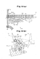
- FIG. 16(a) and 16(b) A ninth embodiment shown in Figs. 16(a) and 16(b) will now be described. Same components as those of the seventh embodiment in Figs. 12 to 14(b) are provided with the same reference numerals.
- the fit hole 56 extends through a capturing block 55B constituting a passage forming body 63B and a capturing pipe 58B is fitted and fixed to the fit hole 56.
- the capturing pipe 58B passes through the fit hole 56 and an outlet 585B of the capturing pipe 58B is opened downward at the outside of the capturing block 55B.
- a passage in the capturing pipe 58B is a capture passage 65 constituted of a passage 583B heading for the front (front of the deformed reed 12) of the guide passage 121 from the inside of the guide passage 121 and a downward passage 584B heading downward while heading for the front (front of deformed reed 12) of the guide passage 121.
- the capture passage 65 is opened only to the lower surface of the passage forming body 63B. That is, the whole of the outlet 585B of the capture passage 65 can be vertically seen from the bottom.
- the passage 583B extends in the direction orthogonally intersecting wit the direction in which the guide passage 121 extends similarly to the case of the passage 583 of the seventh embodiment.
- the air supply hole 60 is formed on the side 554 of the capturing block 55B and the air pipe 29 is connected to the air supply hole 60.
- the air pipe 29 is connected to a non-illustrated air pressure supply source through a non-illustrated electromagnetic on-off valve.
- a stretch nozzle 61B is formed on the peripheral wall of the capturing block 55B for forming the fit hole 56 and the peripheral wall of the capturing pipe 58B.
- the stretch nozzle 61B is connected with the air supply hole 60 and pressurized air supplied to the air supply hole 60 via the air pipe 29 is jetted from the stretch nozzle 61B.
- the jet direction of the stretch nozzle 61B aims at the outlet 585B of the capturing pipe 58B and the air jetted from the stretch nozzle 61B heads downward in the downward passage 584B in the capturing pipe 58B.
- the second weft detector 15 has a detection area in the extension area of the outlet 585B of the capturing pipe 58B and detects whether the weft Y reaches the extension area of the outlet 585B. When the weft Y is excessively inserted or cut, the weft Y passes through the detection area of the second weft detector 15.
- a branch channel 66 is formed on the block body 21 constituting the capturing block 16 so that the branch channel 66 reaches the fit holes 24 and 25 from the lower surface 210.
- the branch channel 66 constituting a capture passage 38F together with the passages 263 and 273 is opened to the lower surface 210 (that is, lower surface of a passage forming body 39F) of the capturing block 16 constituting the passage forming body 39F.
- the branch channel 66 plays the role similar to the groove 23 of the first embodiment.
- An outlet 651 of the branch channel 66 opened to the outside of the passage forming body 39F is only opened downward. That is, the whole of the outlet 651 of the branch channel 66 can be vertically seen from the bottom.
- the leading end Ye of a weft constituting the trimmed selvage W1 does not enter the branch channel 66 from the outlet 651.
- a configuration of opening the outlet 651 of the branch channel 66 only downward prevents the leading end Ye of a weft constituting the trimmed selvage W1 from entering the branch channel 66.
- the present invention may be embodied in the following manners.
- the second embodiment it is also allowed to stop the air jet at the stretch nozzles 312 and 30 after the leading end of the weft Y is blown into the third capturing pipe 44.
- the same advantage as the item (1-7) of the first embodiment can be obtained.
- first capturing pipe 26 and second capturing pipe 27 integrally with the block body 21.
- first capturing pipe 26A and second capturing pipe 27A integrally with the block body 21A.
Abstract
Description
- The present invention relates to a jet loom for inserting a weft along a guide passage by the air jet action of a weft-inserting nozzle, particularly to a jet loom provided with a weft tensioner for introducing the weft into a capture passage by an air flow jetted from a stretch nozzle and capturing the weft.
- A jet loom takes out a weft from a weft-length-measurement storage apparatus by the air jet action of a weft-inserting nozzle. Taking-out of a weft from the weft-length-measurement storage apparatus is controlled so as to insert a weft having a length for one time of weft insertion. That is, the weft-length-measurement storage apparatus is changed to a state capable of taking out a weft and a state not capable of taking out a weft. When the weft-length-measurement storage apparatus is changed to a state not capable of taking out a weft and taking-out of the weft is prevented, a weft having a length for one-time weft insertion is inserted. When preventing taking-out of a weft, a tension wave heading for the leading end of a weft from the weft-length-measurement storage apparatus is generated in a flying weft. The tension wave reaches the leading end of the weft and then returns to the direction opposite to the traveling direction of the weft.
- The flown weft is once extended by several percents by the air jet action of a weft-inserting nozzle and the inertia of the weft. Thereafter, yarn vibration followed by looseness is generated due to the propagation action of the tension wave thereafter. When beating is performed in the state of large weft looseness, weft tension differs at the right and left of fabric and the fabric quality is deteriorated.
- Weft tensioners for solving the above problem are disclosed in
Patent Documents 1 to 5. The weft tensioners respectively provide a proper tension to an inserted weft at the time of beating. The weft tensioners disclosed inPatent Documents 1 and 2 are respectively set on a side of the sley or loom corresponding to the weft-insertion terminal. In the case of each of these apparatuses, air is blown into a pipe from a nozzle so as to traverse a weft guide passage and the leading end of a weft flown through the guide passage is introduced into the pipe from the nozzle. Thereby, the leading end of the weft is bent due to an air flow and captured in the pipe and tension is applied to the weft. - In the case of the apparatuses disclosed in
Patent Documents 3 and 4, a nozzle is located on the front side of a reed and a capturing pipe is located on the back of the reed. The air jetted from the nozzle transverses the weft guide passage at the front of the reed and blown into the capturing pipe and the leading end of a weft flown through the guide passage is introduced into the capturing pipe due to supply of the air. Thereby, the leading end of the weft is bent by air flow and captured in the capturing pipe, and tension is applied to the weft. - In the case of the apparatus disclosed in Patent Document 5, an air blower is built in a weft guide passage formed at the front side of a reed. The leading end of a weft flown through the guide passage enters the air blower to receive the action of an air flow.
- However, in the case of apparatuses disclosed in
Patent Documents 1 and 2, it is necessary to set a weft tensioner to the position at the weft-insertion terminal overlapped with a reed viewed from weft inserting direction. Therefore, when weaving a fabric having a weaving width smaller than the length of a reed in the weft inserting direction, it is necessary to decrease the entire length of the reed by cutting the portion of the reed at the weft inserting end or increase the length of a trimmed selvage. When decreasing the entire length of the reed, it is necessary to use a new reed having a length equal to that of the reed before cut in order to weave a fabric having a weaving width possible before cutting the reed. When increasing the length of the trimmed selvage, the loss of a weft cannot be avoided. - In the case of the apparatuses disclosed in
Patent Documents 3 and 4, problems produced in the apparatuses disclosed inPatent Documents 1 and 2 do not occur because it is possible to change the attaching position of a capturing pipe in the direction in which a guide passage is extended. However, to smoothly insert a weft into a capturing pipe located on the back of a reed, a slit-like gap is formed by inserting a pair of insertion pins attached to the capturing pipe between reed wings. A configuration of inserting insertion pins between reed wings may deform and loosen a bonded portion fixing the top and bottom. When the bonded portion is deformed and loosened, it is impossible to keep a reed wing interval at the normal interval. When the reed wing not kept at the normal interval is used in a weaving width, weaving stripes extending in the warp direction (warp stripe) occur in a fabric and the fabric quality is extremely deteriorated. - In the case of the device disclosed in Patent Document 5, a sufficient weft tension cannot be obtained because the leading end of a weft entering an air blower is captured in a linear state.
- Patent Document 1:
Japanese Examined Patent Publication No. 57-17982 - Patent Document 2:
Japanese Laid-Open No. H10-204752 - Patent Document 3:
Japanese Laid-Open Utility-Model Publication No. 60-63580 - Patent Document 4:
Japanese Laid-Open Utility Model Publication No. H2-115583 - Patent Document 5:
Japanese Examined Patent Publication No. 58-38544 - The present invention can correspond to a change of weaving widths without deteriorating the weaving quality and moreover, it is an object of the present invention to provide a weft tensioner which can provide a sufficient tension for a weft.
- To achieve the above object, in a jet loom for inserting a weft along a guide passage by the jet action of a weft inserting nozzle, the present invention provides a weft tensioner having a passage forming body for forming a capture passage and a stretch nozzle to introduce a weft into the capture passage by an air flow jetted from the stretch nozzle in order to capture the weft in the capture passage. The passage forming body is located on the front side of the guide passage and it is possible to change the position of the passage forming body along the guide passage. At least a part of the capture passage extends in the direction intersecting with the direction along which the guide passage extends.
- The leading end of the weft introduced into the capture passage is captured by the capture passage while it is bent. A configuration for capturing the leading end of the weft while it is bent by an air flow provides a sufficient tension for the weft. In the case of the passage forming body having the capture passage, it is unnecessary to increase the gap between reed wings like a conventional device for passing a weft between adjacent reed wings and introducing the weft into a capturing pipe. Therefore, a fabric is not damaged due to increase of the reed-wing interval. Moreover, because it is possible to change the position of the passage forming body, it is possible to correspond to the change of a weaving width.
-
- Fig. 1(a) is a perspective view showing a jet loom provided with a weft tensioner according to a first embodiment of the present invention, and Fig. 1(b) is an enlarged view of an essential portion of the weft tensioner in Fig. 1(a) ;
- Fig. 2 is a cross-sectional plan view of the jet loom in Fig. 1 (a) ;
- Fig. 3(a) is a cross-sectional side view of the weft tensioner in Fig. 1(a), and Fig. 3(b) is a cross-sectional view of the essential portion of the weft tensioner in Fig. 3(a);
- Fig. 4 is a cross-sectional plan view showing a beating state of the jet loom in Fig. 2;
- Fig. 5 is a graph showing a change of frictional forces between a weft and a passage forming body;
- Fig. 6 is a perspective view of an essential portion showing a weft tensioner according to a second embodiment of the present invention;
- Fig. 7 is a cross-sectional plan view of the weft tensioner in Fig. 6;
- Fig. 8(a) is a cross-sectional plan view showing a weft tensioner according to a third embodiment of the present invention, and Fig. 8(b) is a cross-sectional side view of the weft tensioner in Fig. 8(a);
- Fig. 9 is a cross-sectional plan view showing a weft tensioner according to a fourth embodiment of the present invention;
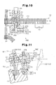
- Fig. 10 is a cross-sectional plan view showing a weft tensioner according to a fifth embodiment of the present invention;
- Fig. 11 is a cross-sectional side view showing a weft tensioner according to a sixth embodiment of the present invention;
- Fig. 12 is a perspective view of an essential portion showing a weft tensioner according to a seventh embodiment of the present invention;
- Fig. 13 is a cross-sectional plan view of the weft tensioner in Fig. 12;
- Fig. 14(a) is a cross-sectional side view of the weft tensioner in Fig. 12, and Fig. 14(b) is a cross-sectional view of an essential portion of the weft tensioner in Fig. 12;
- Fig. 15(a) is a cross-sectional plan view showing a weft tensioner according to an eighth embodiment of the present invention, and Fig. 15(b) is a cross-sectional side view of the weft tensioner in Fig. 15(a);
- Fig. 16(a) is a perspective view of an essential portion showing a weft tensioner according to a ninth embodiment of the present invention, and Fig. 16(b) is a cross-sectional view of an essential portion the weft tensioner in Fig. 16(a); and
- Fig. 17(a) is a cross-sectional side view showing a weft tensioner according to a tenth embodiment of the present invention, and Fig. 17(b) is a cross-sectional plan view of the weft tensioner in Fig. 17(a);
- A first embodiment according to the present invention will be described below by referring to Figs. 1(a) to 5.
- As shown in Fig. 1(a), a jet loom having a weft tensioner is provided with a
sley 11 and adeformed reed 12 is vertically arranged and fixed to thesley 11. The lower portion of thedeformed reed 12 is fastened and fixed by awedge member 35 in agroove 111 formed on the upper surface of thesley 11. - A
weft guide passage 121 is formed on the front surface of thedeformed reed 12. A weft Y taken out from a non-illustrated weft-inserting main nozzle flies in theguide passage 121 by the relay jet actions of a plurality of weft inserting auxiliary nozzles 13 (only one in Fig. 1(a)). The weft Y is taken out from a non-illustrated winding-type weft-length-measurement storage apparatus by the air jet action of a weft inserting main nozzle. - A
first weft detector 14 is set between a ground warp T1 for forming a fabric W and a selvage T2 for forming a trimmed selvage W1 and asecond weft detector 15 is arranged at the side of the selvage T2. Each of thefirst weft detector 14 and thesecond weft detector 15 is the reflective photoelectric sensor type and attached to thesley 11. Thefirst weft detector 14 andsecond weft detector 15 respectively have a detection area in theguide passage 121 to detect whether the weft Y arrives in theguide passage 121. - A
weft capturing block 16 is set between the selvage T2 and thesecond weft detector 15. The capturingblock 16 is provided with ablock body 21 and asupport leg 22 connected to the lower portion of theblock body 21. The capturingblock 16 is attached to thesley 11. - As shown in Fig. 3(a), a tilted attaching
surface 17 is formed on the front surface of thesley 11. Asupport groove 18 is formed on the attachingsurface 17 so as to extend along the longitudinal direction of thesley 11. Thesupport groove 18 includes asmall width portion 181 at the attachingsurface 17 and alarge width portion 182 at the back side and astep 183 is formed between thesmall width portion 181 and thelarge width portion 182. Thestep 183 extends in parallel with the attachingsurface 17. Thesupport leg 22 of the capturingblock 16 is connected to the attachingsurface 17. A pair of bolts 19 (refer to Fig. 1(b)) are inserted into thesupport leg 22. The distal end of ascrew portion 191 of eachbolt 19 protrudes from thesupport leg 22 and alock nut 20 is screwed to the protruded end of thescrew portion 191. - A hexagonal
column head portion 192 of eachbolt 19 is housed in thelarge width portion 182 and the maximum diameter of thehead portion 192 is larger than the width of thelarge width portion 182. Therefore, corners of thehexagonal head portion 192 contact the inner wall surface of thelarge width portion 182 and thereby, thelock nut 20 can be fastened. Thehead portion 192 is pressed against thestep 183 because thelock nut 20 is fastened and the support leg 22 (that is, capturing block 16) is fixed to thesley 11. - The weft-inserting
auxiliary nozzle 13 andweft detectors sley 11 by the means same as the means (bolt 19 and lock nut 20) for attaching the capturingblock 16 to thesley 11. - A
groove 23 is formed on anupper surface 211 of theblock body 21. Thegroove 23 is opened to afront surface 213 of theblock body 21. - As shown in Fig. 2, a pair of
fit holes block body 21. Thefit hole 24 is formed so as to reach thegroove 23 from a back 212 of theblock body 21. Thefit hole 25 is formed so as to reach thegroove 23 from a side 214 (side of thesecond weft detector 15 side) of theblock body 21. - A first
weft capturing pipe 26 is fitted to thefit hole 24 and a secondweft capturing pipe 27 is fitted to thefit hole 25. Apassage 263 in thefirst capturing pipe 26 extends so as to orthogonally intersect with the direction in which theguide passage 121 extends. The protruded end of thefirst capturing pipe 26 protruded from thefit hole 24 has a diagonally-cut shape and a diagonally-shapedintroduction port 261 of thefirst capturing pipe 26 is caught in theguide passage 121 and faces the selvage T2 side. That is, theintroduction port 261 is made to enter theguide passage 121 so as to be connected with theguide passage 121 by facing the direction opposite to the traveling direction of the weft Y. - The protruded end of the
second capturing pipe 27 protruded from thefit hole 25 has a diagonally-cut shape and an diagonally-shapedoutlet 271 of thesecond capturing pipe 27 is caught in theguide passage 121. Theoutlet 271 of thesecond capturing pipe 27 is faced to the downstream side of theguide passage 121 so as to intersect with theguide passage 121 and theoutlet 271 is located upstream of thesecond weft detector 15 on theguide passage 121. - As shown in Fig. 3(b), an
air supply hole 28 is formed on alower surface 210 of theblock body 21 and anair pipe 29 is connected to theair supply hole 28. Theair pipe 29 is connected to a non-illustrated air pressure supply source through a non-illustrated electromagnetic on-off valve. - As shown in Fig. 2, a
stretch nozzle 30 is formed on the side wall surface of theblock body 21 for forming thegroove 23. Thestretch nozzle 30 is connected to theair supply hole 28, and pressurized air blown into theair supply hole 28 via theair pipe 29 is jetted from thestretch nozzle 30. The jet direction of thestretch nozzle 30 aims at anintroduction port 272 of thesecond capturing pipe 27 and the air jetted from thestretch nozzle 30 traverses thegroove 23 and is blown into theintroduction port 272 of thesecond capturing pipe 27. - A
curved surface 216 is formed between the back 212 and a side 215 (side at the first weft detector 14) of theblock body 21. - As shown in Fig. 3(a), a
nozzle forming body 31 is located on the back side of thedeformed reed 12. Asupport leg 311 of thenozzle forming body 31 is fastened and fixed by awedge member 36 in thegroove 111. Ascrew 37 passes through thewedge member 36 and screwed to ascrew hole 112 at the bottom of thegroove 111. Thewedge member 36 fixes thesupport leg 311 in thegroove 111 by fastening thescrew 37. A plurality of screw holes 112 are formed along the length direction of thegroove 111 and it is possible to select the position of thenozzle forming body 31 in the length direction of thegroove 111 by selecting thescrew hole 112. - As shown in Fig. 2 and Fig. 3(a), an
air supply hole 32 is formed at the back of thenozzle forming body 31 and anair pipe 33 is connected to theair supply hole 32. Theair pipe 33 is connected to a non-illustrated air pressure supply source through a non-illustrated electromagnetic on-off valve. Abuffering plate 34 made of rubber is attached to the front of thenozzle forming body 31. Astretch nozzle 312 is formed at the front of thenozzle forming body 31 and a throughport 341 is formed on thebuffering plate 34. Astretch nozzle 312 is connected to theair supply hole 32 and pressurized air blown into theair supply hole 32 via theair pipe 33 is jetted from thestretch nozzle 312. The jet direction of thestretch nozzle 312 aims at theintroduction port 261 of thefirst capturing pipe 26. The air jetted from thestretch nozzle 312 passes between the throughport 341 and areed wing 122 adjacent to thedeformed reed 12, traverses theguide passage 121, and is blown into theintroduction port 261 of thefirst capturing pipe 26. - Air jet from the
stretch nozzles introduction port 261 of thefirst capturing pipe 26. The leading end of the weft Y flown through theguide passage 121 is blown into thefirst capturing pipe 26 by the air jet from thestretch nozzle 312. The leading end of the weft Y blown into thefirst capturing pipe 26 passes through anoutlet 262 of thefirst capturing pipe 26 and reaches thegroove 23. The leading end of the weft Y reaching thegroove 23 is blown into theintroduction port 272 of thesecond capturing pipe 27 by the air jet from thestretch nozzle 30. When the leading end of the weft Y reaches the middle of thesecond capturing pipe 27, taking-out of the weft from the above-described weft-length-measurement storage apparatus is prevented. - Stop of air jet from the
stretch nozzle 312 is performed after the time when the leading end of the weft Y is regarded as having been blown into thesecond capturing pipe 27. The air jet flow acting on the leading end of the weft Y blown into thesecond capturing pipe 27 applies a tension to the weft Y. - The
passage 263 andgroove 23 in thefirst capturing pipe 26 and apassage 273 in thesecond capturing pipe 27 constitute aweft capture passage 38, and thecapture passage 38 has a portion extending in a direction intersecting with the direction in which theguide passage 121 extends. The capturingblock 16, first capturingpipe 26, and second capturingpipe 27 constitute apassage forming body 39 for forming thecapture passage 38. Thefirst capturing pipe 26 is a cylindrical portion caught in theguide passage 121 so that theintroduction port 261 of thecapture passage 38 faces the direction opposite to the traveling direction of the weft Y so as to connect with theguide passage 121. - The
groove 23 constituting a part of thecapture passage 38 is located in the middle of thecapture passage 38 and functions as a branch channel opened to the outside of thepassage forming body 39. The intersecting portion between the jet direction of thestretch nozzle 312 and the jet direction of thestretch nozzle 30 is located at the connecting portion between thecapture passage 38 and the branch channel (groove 23). Theintroduction port 272 functions as a direction change port located at the downstream side of the connecting portion between the branch channel (groove 23) and thecapture passage 38. - The weft Y is beaten in a state in which the leading end of the weft Y is bent and captured in the
capture passage 38. Fig. 4 shows a state in which the weft Y is beaten by the cloth fell Wo of the fabric W. - The following advantages are obtained from the first embodiment.
- (1-1) The direction in which the
passage 263 in thefirst capturing pipe 26 extends intersects (orthogonally intersects) with the direction in which theguide passage 121 extends. The leading end of the weft Y introduced into thecapture passage 38 extending in the direction is captured while it is bent by the air flow from thestretch nozzles - (1-2) The leading end of the weft Y introduced into the
capture passage 38 contacts an inner-peripheral margin 264 (illustrated in Figs. 2 and 4) of theintroduction port 261 of thefirst capturing pipe 26, an inner-peripheral margin 265 (illustrated in Figs. 2 and 4) of theoutlet 262, and an inner-peripheral margin 274 (illustrated in Figs. 2 and 4) of theintroduction port 272 of thesecond capturing pipe 27, and is sharply bent. The inner-peripheral margins capture passage 38 to bend a weft. The configuration for sharply bending the leading end of the weft Y in thecapture passage 38 provides a preferable tension applying action to the weft Y and an advantage for greatly restraining the looseness of the weft Y due to yarn vibration. - (1-3) The
passage forming body 39 provided with thecapture passage 38 for capturing the leading end of the weft Y while it is bent is present at the front side (front side of the deformed reed 12) of theguide passage 121. The leading end of the weft Y flown through theguide passage 121 is introduced into theintroduction port 261 at the front side of theguide passage 121. Therefore, it is not necessary to increase the interval between reed wings like a conventional device which passes a weft betweenadjacent reed wings 122 and introduces the weft to a capturing pipe. Therefore, the fabric W is not damaged due to increase of reed wing interval. - (1-4) The
passage forming body 39 can move along the direction in which theguide passage 121 extends while loosening thelock nut 20. That is, thepassage forming body 39 can change the position along theguide passage 121. Therefore, also when the weaving width of a fabric is changed, it is possible to set thepassage forming body 39 to a proper position in the direction in which theguide passage 121 extends and easily correspond to change of a weaving width. - (1-5) The
introduction port 261 tilted relative to the direction in which theguide passage 121 extends is caught in theguide passage 121. That is, theintroduction port 261 of thecapture passage 38 faces the direction opposite to the traveling direction of the weft Y (confronting direction) and links with theguide passage 121. A configuration of linking theintroduction port 261 with theguide passage 121 is effective to improve the certainty for introducing the leading end of the weft Y flown through theguide passage 121 into thecapture passage 38. - (1-6) The air flow jetted from the
stretch nozzle 30 intersects with the air flow jetted from thestretch nozzle 312. A part of the leading end of the weft Y introduced into thepassage 263 of thefirst capturing pipe 26 is captured into thepassage 273 of thesecond capturing pipe 27 by the air flow jetted from thestretch nozzle 30. That is, the air flow jetted from thestretch nozzle 30 is jetted from thestretch nozzle 312, intercepts the air flow passing through thefirst capturing pipe 26 andgroove 23, and is blown into thesecond capturing pipe 27. As a result, the leading end of the weft Y in thecapture passage 38 is captured while it is bent in thecapture passage 38. A configuration of bending the weft Y in thecapture passage 38 by the air flow jetted from thestretch nozzle 30 is preferable to provide a sufficient tension for the weft Y. - It is preferable that the flow rate of an air flow jetted from the
stretch nozzle 30 at theintroduction port 272 of thesecond capturing pipe 27 is two times larger than the flow rate of the air flow jetted from thestretch nozzle 312 at theoutlet 262 of thefirst capturing pipe 26. - (1-7) The curve E in the graph in Fig. 5 shows a change of the frictional force between the weft Y and the
passage forming body 39 when changing the air jet pressure at thestretch nozzle 312 in a range between 0 and 0.5 MPa and setting the air jet pressure of thestretch nozzle 30 to 0.3 MPa. The graph in Fig. 5 shows that the frictional force is maximized when the air jet pressure at thestretch nozzle 312 is zero. That is, a state of jetting air only from thestretch nozzle 30 while the leading end of the weft Y is inserted into thesecond capturing pipe 27 is advantageous to restrain the looseness of the weft Y due to yarn vibration because of increasing the frictional force compared to the state of jetting air from both thestretch nozzles - (1-8) The air flow jetted from the
stretch nozzle 312 of thenozzle forming body 31 located on the back side of thedeformed reed 12 blows the leading end of the weft Y into thefirst capturing pipe 26 through theguide passage 121 together with the air flow jetted from the weft-insertingauxiliary nozzle 13. That is, the air flow jetted from thestretch nozzle 312 is jetted from the weft-insertingauxiliary nozzle 13, intercepts the air flow flowing through theguide passage 121, and blows the leading end of the weft Y into thefirst capturing pipe 26. The air flow blown into theintroduction port 261 of thecapture passage 38 from thestretch nozzle 312 at the back of thedeformed reed 12 improves the certainty for introducing the leading end of the weft Y flown through theguide passage 121 into thecapture passage 38. - It is preferable that the flow rate of the air flow from the
stretch nozzle 312 at theintroduction port 261 of thefirst capturing pipe 26 is approximately five times larger than the flow rate of the air flow jetted from the weft-insertingauxiliary nozzle 13 at a position close to theintroduction port 261 of thefirst capturing pipe 26. - (1-9) The
first weft detector 14 andsecond weft detector 15 respectively have a detection area in theguide passage 121 and theoutlet 271 of thecapture passage 38 is faced to the downstream side of theguide passage 121 so as to intersect with theguide passage 121. - As disclosed in
Patent Document 4, in the case of a jet loom, a first weft detector for detecting whether a weft reaches a predetermined position and a second weft detector for detecting whether a weft is inserted longer than a predetermined length are generally used. When the weft Y reaches theintroduction port 261 of thefirst capturing pipe 26, thefirst weft detector 14 detects the attainment of the weft Y. When the weft Y reaches the detection area of thesecond weft detector 15, thesecond weft detector 15 detects the attainment of the weft Y. That is, in the case of this embodiment, thefirst weft detector 14 detects whether a weft reaches a predetermined position, and thesecond weft detector 15 detects whether a weft is inserted longer than a predetermined length. Thesecond weft detector 15 detects cases in which the joint of the weft Y or only a cover yarn covering the surface of a stretch yarn is removed. - A configuration of facing the
outlet 271 of thecapture passage 38 to the downstream side of theguide passage 121 so that theoutlet 271 intersects with theguide passage 121 makes it possible to detect presence or absence of the weft Y in theguide passage 121 by thesecond weft detector 15. - (1-10) When brining the
nozzle forming body 31 located on the back side of thedeformed reed 12 into direct contact thereed wing 122, thenozzle forming body 31 andreed wing 122 are abraded and damaged due to the vibration of thereed wing 122. Thebuffering plate 34 made of rubber present between thenozzle forming body 31 and thedeformed reed 12 has advantages of avoiding the direct contact between thenozzle forming body 31 and thereed wing 122 and preventing abrasion damage. - (1-11) When the
groove 23 of theblock body 21 does not open to theupper surface 211 andfront surface 213, the flow rate of the air flow jetted from thestretch nozzle 312 is not easily attenuated. When the air flow jetted from thestretch nozzle 312 collides with the air flow jetted from thestretch nozzle 30 in a state in which the flow rate of the air flow jetted from thestretch nozzle 312 is not greatly attenuated, the leading end of the weft Y is not easily direction-changed toward theintroduction port 272 of thesecond capturing pipe 27. Moreover, when the flow rate of the air flow jetted from thestretch nozzle 312 is not greatly attenuated, the leading end of the weft Y does not easily contact the inner-peripheral margin of theintroduction port 272 of thesecond capturing pipe 27 and the tension applying effect decreases. - A configuration of opening the
groove 23 to theupper surface 211 andfront surface 213 has an advantage that the flow rate of the air flow jetted from thestretch nozzle 312 is easily attenuated. - (1-12) When the
deformed reed 12 backs from the state in Fig. 4 in which the weft Y is beaten to the cloth fell Wo of the fabric W, the leading end of the weft Y in thecapture passage 38 is slowly removed from the inside of thecapture passage 38. When thepassage forming body 39 backing together with thedeformed reed 12 comes closely to the position shown by a chain line in Fig. 4, the weft Y contacts thecurved surface 216. It is unnecessary to provide a tension for the weft Y after beating, and it is preferable that the leading end is smoothly removed from thecapture passage 38. Thecurved surface 216 contributes to the decrease of the resistance applied to the weft Y to be removed from thecapture passage 38. - Then, a second embodiment in Figs. 6 and 7 is described. The same reference numerals are provided for the same components as those of the first embodiment.
- As shown in Fig. 7, a
fit hole 40 is formed on ablock body 21A of apassage forming body 39A. Afirst capturing pipe 26A fitted to thefit hole 40 diagonally intersects with theguide passage 121 so that the direction in which thepassage 263 extends faces the downstream side of theguide passage 121. A diagonally-shapedintroduction port 261A of thefirst capturing pipe 26A faces thestretch nozzle 312. - A
fit hole 41 is formed on theblock body 21A so as to extend toward theside 214 from thegroove 23 and asecond capturing pipe 27A is fitted to thefit hole 41. The jet direction at thestretch nozzle 30 aims at anintroduction port 272A of thesecond capturing pipe 27A and the air jetted from thestretch nozzle 30 traverses thegroove 23 and is blown into theintroduction port 272A of thesecond capturing pipe 27A. - As shown in Fig. 6, a
groove 42 is formed on theupper surface 211 of theblock body 21A. Thegroove 42 is opened to theside 214. - As shown in Fig. 7, the
groove 42 connects with thefit hole 41 in series. Afit hole 43 is formed on theblock body 21A so as to extend from the back 212 toward thegroove 42 and athird capturing pipe 44 is fitted to thefit hole 43. Astretch nozzle 45 is formed on the side wall surface of theblock body 21A. The jet direction at thestretch nozzle 45 aims at anintroduction port 441 of thethird capturing pipe 44. Thestretch nozzle 45 is connected to anair supply hole 46 and theair supply hole 46 is connected to a non-illustrated pressure-air supply source though anair pipe 47 shown in Fig. 6 and a non-illustrated electromagnetic on-off valve. The air jetted from thestretch nozzle 45 transverses thegroove 42 and is blown into theintroduction port 441 of thethird capturing pipe 44. - The portion of the
third capturing pipe 44 in theblock body 21A is parallel with thefirst capturing pipe 26A and the end of thethird capturing pipe 44 is faced to the downstream side of theguide passage 121 so as to intersect with theguide passage 121 at a shallow angle. Anoutlet 442 of thethird capturing pipe 44 is present at the upstream side of thesecond weft detector 15 with respect to theguide passage 121. - The
passage 263 and groove 23 of thefirst capturing pipe 26A,passage 273 and groove 42 of thesecond capturing pipe 27A, and apassage 443 of thethird capturing pipe 44 constitute acapture passage 48 and thecapture passage 48 has a portion extending in the direction intersecting with the direction in which theguide passage 121 extends. The leading end of the weft Y blown into thefirst capturing pipe 26A by the air flow from thestretch nozzle 312 is blown into thesecond capturing pipe 27A by the air flow from thestretch nozzle 30. The leading end of the weft Y blown into thesecond capturing pipe 27A is blown into thethird capturing pipe 44 by the air flow from thestretch nozzle 45. The leading end of the weft Y captured in thecapture passage 48 reaches a position close to the end of thethird capturing pipe 44. - In the case of the second embodiment, the same advantages as those in Items (1-1) to (1-4), (1-6), and (1-8) to (1-12) of the first embodiment are obtained. Moreover, the
capture passage 48 having more bent portions than those of thecapture passage 38 further effectively restrains yarn vibration generated in the weft Y and further improves the tension applying performance. Improvement of the tension applying performance contributes to decrease of air consumption for capturing the weft Y. - Moreover, a configuration of diagonally intersecting the
first capturing pipe 26A with theguide passage 121 is preferable because the bent angle of a weft at the inner-peripheral margin of theintroduction port 261A of thefirst capturing pipe 26A and that of a weft at the inner-peripheral margin of anoutlet 262A of thefirst capturing pipe 26A become sharp. - Furthermore, a configuration of opening the
groove 42 of theblock body 21A to theupper surface 211 andside 214 of theblock body 21A has an advantage that the air flow jetted from thestretch nozzle 30 is easily attenuated. - Then, a third embodiment in Figs. 8(a) and 8(b) will be described below. The reference numerals are used for the same components as those in the
embodiment 1. - A
first capturing pipe 26B is attached to ablock body 21B constituting apassage forming body 39B. Anintroduction port 261B of thefirst capturing pipe 26B is caught in theguide passage 121 to face the direction (confronting direction) opposite to the traveling direction of the weft Y. Anoutlet 271B of asecond capturing pipe 27B of theblock body 21B is caught in theguide passage 121 to face the traveling direction of the weft Y. Thestretch nozzle 30 aims at anintroduction port 272B of thesecond capturing pipe 27B. - The
passage 263 and groove 23 of thefirst capturing pipe 26B and thepassage 273 of thesecond capturing pipe 27B constitute acapture passage 49 and thecapture passage 49 has a portion extending in the direction intersecting with the direction in which theguide passage 121 extends. The leading end of the weft Y flown through theguide passage 121 is blown into thefirst capturing pipe 26B by the air flow from the weft-inserting auxiliary nozzle 13 (refer to Fig. 1(a)). The leading end of the weft Y blown into thefirst capturing pipe 26B is blown in to thesecond capturing pipe 27B by the air flow from thestretch nozzle 30. - An
elastic ring 50 made of rubber serving as an elastic material is fitted to thefirst capturing pipe 26B serving as a cylindrical portion for forming theintroduction port 261B of thecapture passage 49. Moreover, anelastic ring 51 made of rubber serving as an elastic material is fitted to thesecond capturing pipe 27B. The elastic rings 50 and 51 contact the wall surface of thereed wing 122 forming theguide passage 121. - In the case of the third embodiment, the same advantages those of Items (1-1), (1-3) to (1-6), (1-9), and (1-11) of the first embodiment are obtained. Moreover, because the
nozzle forming body 31 of the first embodiment is unnecessary, the configuration is simplified. - Furthermore, in the
guide passage 121, the gap between the outer periphery of thefirst capturing pipe 26B and the wall surface of thereed wing 122 is closed by theelastic ring 50. Therefore, the leading end of the weft Y is securely introduced into thefirst capturing pipe 26B. Moreover, because it is prevented by theelastic ring 50 that thereed wing 122 directly contacts thefirst capturing pipe 26B, abrasion damage due to the vibration of thereed wing 122 at the time of beating is avoided. Abrasion damage is also avoided by theelastic ring 51. - The present invention may be applied as fourth, fifth, and sixth embodiments shown in Figs. 9, 10, and 11. In these embodiments, same components as the case of the first embodiment use the same reference numerals.
- In the case of the fourth embodiment in Fig. 9, a capturing
block 16C constituting a passage forming body is attached to thefirst weft detector 14. Because thefirst weft detector 14 is disposed on the outside of the selvage T2, it is possible to narrow the gap between the ground warp T1 and the selvage T2 compared to the case of the first embodiment. This contributes to decrease of the weft length for one-time weft insertion and decrease of the weft consumption. - In the case of the fifth embodiment in Fig. 10, a
second capturing pipe 27D attached to ablock body 21D constituting apassage forming body 39D orthogonally intersects with thegroove 23 and the direction of thesecond weft detector 15 is opposite to the case of the first embodiment. That is, the detection area of thesecond weft detector 15 is set on the extension line of thepassage 273 of thesecond capturing pipe 27D. Thepassage 263 and groove 23 of thefirst capturing pipe 26 and thepassage 273 of thesecond capturing pipe 27D constitute acapture passage 52. When the weft Y is excessively inserted or the weft is cut, the weft Y passes through the detection area of thesecond weft detector 15. - In the case of the sixth embodiment in Fig. 11, a
second capturing pipe 27E attached to ablock body 21E constituting apassage forming body 39E orthogonally intersects with apassage 53 to be opened to thefront surface 213 and points upward. The jet direction at astretch nozzle 30E formed at the bottom of thepassage 53 aims at anintroduction port 272E of thesecond capturing pipe 27E. The leading end of the weft Y introduced into thefirst capturing pipe 26 is blown into thesecond capturing pipe 27E by the air flow from thestretch nozzle 30E. Thepassages first capturing pipe 26 and thepassage 273 of thesecond capturing pipe 27E constitute acapture passage 54. - Then, the seventh embodiment in Figs. 12 to 14(b) is described. Same components as the case of the first embodiment are provided with the same reference numerals.
- As shown in Fig. 12, a capturing
block 55 is fastened and joined to the attachingsurface 17 of thesley 11 by using a pair ofbolts 19 and a pair of nuts 20. - As shown in Fig. 14(b), a pair of
fit holes block 55. Thefit hole 56 is set so as to reach alower surface 552 of the capturingblock 55 from theupper face 551 of theblock 55. Thefit hole 57 is set so as to reach thefit hole 56 from a side 553 (side of the second weft detector 15). Afirst capturing pipe 58 is fitted and fixed to thefit hole 56 and asecond capturing pipe 59 is fitted and fixed to thefit hole 57. Thefirst capturing pipe 58 is fitted up to the middle of thefit hole 56. - As shown in Fig. 14(a), a protruded
portion 581 of thefirst capturing pipe 58 protruded from thefit hole 56 is curved. As shown in Fig. 13, the end of the protrudedportion 581 forms anintroduction port 582 having a diagonally-cut shape. Theintroduction port 582 is caught in theguide passage 121 and faces the selvage T2 side. That is, theintroduction port 582 is made to enter theguide passage 121 so as to face the direction opposite to the traveling direction of the weft Y and connect with theguide passage 121. - A passage in the
first capturing pipe 58 is constituted of apassage 583 heading for the front of the guide passage 121 (front of the deformed reed 12) from the inside of theguide passage 121 and adownward passage 584 heading downward while heading for the front of the guide passage 121 (front of the deformed reed 12). Thepassage 583 extends in the direction orthogonally intersecting with the direction in which theguide passage 121 extends. - The protruded end of the
second capturing pipe 59 protruded from thefit hole 57 forms anoutlet 591 having a diagonally-cut shape. Theoutlet 591 is caught in theguide passage 121. Theoutlet 591 is faced to the downstream side of theguide passage 121 so as to intersect with theguide passage 121 and theoutlet 591 is located upstream of thesecond weft detector 15 for theguide passage 121. - As shown in Fig. 14(b), an
air supply hole 60 is formed at aside 554 of the capturingblock 55 and theair pipe 29 is connected to theair supply hole 60. Theair pipe 29 is connected to a non-illustrated air pressure source through a non-illustrated electromagnetic on-off valve. - A
stretch nozzle 61 is formed on the peripheral wall surface of the capturingblock 55 for forming thefit hole 56. Thestretch nozzle 61 is connected with theair supply hole 60 and the pressurized air supplied to theair supply hole 60 via theair pipe 29 is jetted from thestretch nozzle 61. The jet direction of thestretch nozzle 61 aims at anintroduction port 592 of thesecond capturing pipe 59 and the air jetted from thestretch nozzle 61 traverses thefit hole 56 and is blown into theintroduction port 592 of thesecond capturing pipe 59. - The air jet from the
stretch nozzles introduction port 582 of thefirst capturing pipe 58. The leading end of the weft Y flown through theguide passage 121 is blown into thefirst capturing pipe 58 by the air jet from thestretch nozzle 312. The leading end of the weft Y blown into thefirst capturing pipe 58 passes through anoutlet 585 of thefirst capturing pipe 58 and comes on to thefit hole 56. The leading end of the weft Y coming on to thefit hole 56 by passing through theoutlet 585 heads for the intersecting portion between thefit holes - Hereafter, the portion below the intersecting portion between the
fit holes branch channel 561. The leading end of the weft Y reaching the intersecting portion between thefit holes introduction port 592 of thesecond capturing pipe 59 by the air jet from thestretch nozzle 61. When the leading end of the weft Y reaches the middle of thesecond capturing pipe 59, taking-out of the weft from a weft-length-measurement storage apparatus is prevented. - The air jet from the
stretch nozzle 312 is stopped after the leading end of the weft Y is regarded to be blown into thesecond capturing pipe 59. The air jet flow acting on the leading end of the weft Y blown into thesecond capturing pipe 59 provides tension for the weft Y. - The
passage 583 anddownward passage 584 in thefirst capturing pipe 58 and apassage 593 in thesecond capturing pipe 59 constitute acapture passage 62 and thecapture passage 62 has a portion extending in the direction intersecting with the direction in which theguide passage 121 extends. Thecapture passage 62 locally includes thedownward passage 584 heading downward from the front side of theguide passage 121. An outlet 562 (outlet of fit hole 56) of thebranch channel 561 connected to the end of thedownward passage 584 is opened only downward. That is, the whole of theoutlet 562 of thebranch channel 561 is seen when vertically viewing it from the bottom. Theintroduction port 592 functions as a direction change port of a capture passage located at the downstream side of the connecting portion between thebranch channel 561 and thedownward passage 584. - The capturing
block 55, first capturingpipe 58, and second capturingpipe 59 constitute apassage forming body 63 for forming thecapture passage 62. Thefirst capturing pipe 58 is a cylindrical portion caught in theguide passage 121 so that theintroduction port 582 of thecapture passage 62 faces the direction opposite to the traveling direction of the weft Y and is connected with theguide passage 121. - The leading end of the weft Y introduced into the
capture passage 62 contact an inner-peripheral margin 586 (illustrated in Fig. 13) of theintroduction port 582 of thefirst capturing pipe 58, an inner-peripheral margin 587 (illustrated in Fig. 14(b)) of theoutlet 585, and an inner-peripheral margin 594 (illustrated in Fig. 14(b)) of theintroduction port 592 of thesecond capturing pipe 59 and is sharply bent. The weft Y is beaten while it is captured in a bent shape in thecapture passage 62. - In the case of the seventh embodiment, the same advantages as those in Items (1-1) to (1-6) and Items (1-8) to (1-10) are obtained and the following advantage is obtained.
- (7-1) To avoid the interference between a temple apparatus (not illustrated) for preventing the crimp of the fabric W close to the cloth fell Wo and the passage forming body at the time of beating, it is assumed that the passage forming body is located the downstream of the position of the temple apparatus on the direction (weft inserting direction) in which the
guide passage 121 extends. Then, the length of an inserted weft becomes longer than the case of arranging the passage forming body near the position of the temple apparatus on the direction (weft inserting direction) in which theguide passage 121 extends. This is not preferable for the consumption of a weft. - The
capture passage 62 includes thepassage 583 heading for the front of theguide passage 121 from theintroduction port 582 caught in theguide passage 121 and thedownward passage 584 heading downward by following thepassage 583 as a part of thepassage 62. That is, thecapture passage 62 has a shape of slightly extending toward the front of theguide passage 121 and then immediately heading downward. In the case of the upper surface of thepassage forming body 63 having thecapture passage 62 having the above shape, it is possible to decrease the distance protruded to the front fromguide passage 121 compared to the case of the upper surface (block body 21) of thepassage forming body 39 of, for example, the first embodiment. This is advantageous to avoid the interference with the temple apparatus. - That is, also when arranging the
passage forming body 63 at a position close to the position of the temple apparatus on the direction (weft inserting direction) in which theguide passage 121 extends, it is possible to avoid the interference between thepassage forming body 63 and the temple apparatus. - (7-2) The leading end Ye (illustrated in Fig. 13) constituting the woven trimmed selvage W1 is a leading end of a weft captured in the capture passage of the passage forming body at the time of beating. The passage forming body approaches the leading end Ye of a weft close to the cloth fell Wo at the time of beating. It is assumed that the leading end Ye of a weft constituting the woven trimmed selvage W1 in this case enters the
capture passage 62. Then, the leading end Ye of the weft entering thecapture passage 62 prevents that proper tension is applied to an original weft to be captured by a capture passage in a passage forming body. - The
branch channel 561 connected to the end of thedownward passage 584 plays the same role as the case of thegroove 23 of the first embodiment. Theoutlet 562 of thebranch channel 561 is located on thelower surface 552 of the capturingblock 55. That is, theoutlet 562 of thebranch channel 561 opened to the outside of thepassage forming body 63 is opened only downward and the leading end Ye of a weft constituting the trimmed selvage W1 does not enter thebranch channel 561 from theoutlet 562. A configuration of opening theoutlet 562 of thebranch channel 561 only downward prevents the leading end Ye of a weft constituting the trimmed selvage W1 from entering thebranch channel 561. - An eighth embodiment in Figs. 15(a) and 15(b) will now be described. Same components as those of the seventh embodiment in Figs. 12 to 14(b) and the third embodiment in Figs. 8(a) and 8(b) are provided with the same reference numerals.
- A
first capturing pipe 58A is attached to the capturingblock 55 constituting apassage forming body 63A and an introduction port 582A of thefirst capturing pipe 58A enters theguide passage 121 and faces the direction (confronting direction) opposite to the traveling direction of the weft Y. - A
passage 583A anddownward passage 584 of thefirst capturing pipe 58A and thepassage 593 of thesecond capturing pipe 59 constitute acapture passage 64 and thecapture passage 64 constitutes thecapture passage 64 having a portion extending in the direction intersecting with the direction in which theguide passage 121 extends. The leading end of the weft Y flown through theguide passage 121 is blown into thefirst capturing pipe 58A by the air flow from the weft-inserting auxiliary nozzle 13 (refer to Fig. 1(a)). The leading end of the weft Y blown into thefirst capturing pipe 58A is blown into thesecond capturing pipe 59 by the air flow from thestretch nozzle 61. - An
elastic ring 50 made of rubber serving as an elastic material is fitted to thefirst capturing pipe 58A serving as a cylindrical portion for forming the introduction port 582A of thecapture passage 64. Theelastic ring 50 contacts the wall surface of thereed wing 122 for forming theguide passage 121. - In the case of the eighth embodiment, the same advantages as the third embodiment and seventh embodiment are obtained.
- A ninth embodiment shown in Figs. 16(a) and 16(b) will now be described. Same components as those of the seventh embodiment in Figs. 12 to 14(b) are provided with the same reference numerals.
- The
fit hole 56 extends through acapturing block 55B constituting apassage forming body 63B and a capturingpipe 58B is fitted and fixed to thefit hole 56. The capturingpipe 58B passes through thefit hole 56 and anoutlet 585B of the capturingpipe 58B is opened downward at the outside of the capturingblock 55B. - A passage in the capturing
pipe 58B is acapture passage 65 constituted of apassage 583B heading for the front (front of the deformed reed 12) of theguide passage 121 from the inside of theguide passage 121 and adownward passage 584B heading downward while heading for the front (front of deformed reed 12) of theguide passage 121. Thecapture passage 65 is opened only to the lower surface of thepassage forming body 63B. That is, the whole of theoutlet 585B of thecapture passage 65 can be vertically seen from the bottom. Thepassage 583B extends in the direction orthogonally intersecting wit the direction in which theguide passage 121 extends similarly to the case of thepassage 583 of the seventh embodiment. - As shown in Fig. 16(b), the
air supply hole 60 is formed on theside 554 of the capturingblock 55B and theair pipe 29 is connected to theair supply hole 60. Theair pipe 29 is connected to a non-illustrated air pressure supply source through a non-illustrated electromagnetic on-off valve. - A
stretch nozzle 61B is formed on the peripheral wall of the capturingblock 55B for forming thefit hole 56 and the peripheral wall of the capturingpipe 58B. Thestretch nozzle 61B is connected with theair supply hole 60 and pressurized air supplied to theair supply hole 60 via theair pipe 29 is jetted from thestretch nozzle 61B. The jet direction of thestretch nozzle 61B aims at theoutlet 585B of the capturingpipe 58B and the air jetted from thestretch nozzle 61B heads downward in thedownward passage 584B in the capturingpipe 58B. - The
second weft detector 15 has a detection area in the extension area of theoutlet 585B of the capturingpipe 58B and detects whether the weft Y reaches the extension area of theoutlet 585B. When the weft Y is excessively inserted or cut, the weft Y passes through the detection area of thesecond weft detector 15. - In the case of the ninth embodiment, the same advantages as the items (1-1), (1-3), (1-4), and (1-10) of the first embodiment and Items (7-1) and (7-2) of the seventh embodiment are obtained.
- A tenth embodiment in Figs. 17(a) and 17(B) will be described below. The same reference numerals are used for same components as the case of the first embodiment.
- A
branch channel 66 is formed on theblock body 21 constituting the capturingblock 16 so that thebranch channel 66 reaches the fit holes 24 and 25 from thelower surface 210. Thebranch channel 66 constituting acapture passage 38F together with thepassages passage forming body 39F) of the capturingblock 16 constituting thepassage forming body 39F. Thebranch channel 66 plays the role similar to thegroove 23 of the first embodiment. Anoutlet 651 of thebranch channel 66 opened to the outside of thepassage forming body 39F is only opened downward. That is, the whole of theoutlet 651 of thebranch channel 66 can be vertically seen from the bottom. The leading end Ye of a weft constituting the trimmed selvage W1 does not enter thebranch channel 66 from theoutlet 651. A configuration of opening theoutlet 651 of thebranch channel 66 only downward prevents the leading end Ye of a weft constituting the trimmed selvage W1 from entering thebranch channel 66. - The present invention may be embodied in the following manners.
- In the second embodiment, it is also allowed to stop the air jet at the
stretch nozzles third capturing pipe 44. Thus, the same advantage as the item (1-7) of the first embodiment can be obtained. - In the first embodiment, it is allowed to use a passage to be opened to only the
front surface 213 instead of thegroove 23. - In the second embodiment, it is also allowed to use a passage to be opened only to the
side 214 instead of thegroove 42. - In the first embodiment, it is also allowed to form the
first capturing pipe 26 andsecond capturing pipe 27 integrally with theblock body 21. - In the second embodiment, it is also allowed to form the
first capturing pipe 26A andsecond capturing pipe 27A integrally with theblock body 21A.
Claims (16)
- A weft tensioner in a jet loom for inserting a weft along a guide passage by the air jet action of a weft inserting nozzle, comprising a passage forming body defining a capture passage and a stretch nozzle, and introducing a weft into the capture passage by the air flow jetted from the stretch nozzle in order to capture the weft into the capture passage, the weft tensioner being characterized in that
the passage forming body is located on the front side of the guide passage, the position of the passage forming body can be changed along the guide passage, and at least a part of the capture passage extends in the direction intersecting with the direction in which the guide passage extends. - The weft tensioner according to claim 1, characterized in that a wall surface of the passage forming body defining the capture passage has at least two bent portions for respectively bending the weft.
- The weft tensioner according to claim 1 or 2, characterized in that the capture passage has an introduction port connected with the guide passage.
- The weft tensioner according to claim 3, characterized in that the passage forming body includes a cylindrical portion for forming the introduction port, and the cylindrical portion is caught in the guide passage so that the introduction port faces the direction opposite to the traveling direction of a weft.
- The weft tensioner according to claim 4, characterized in that the outer periphery of the cylindrical portion is covered with an elastic material.
- The weft tensioner according to any one of claims 1 to 5, characterized in that the stretch nozzle is located at the passage forming body, generates the air flow in the capture passage, and bends the weft in the capture passage.
- The weft tensioner according to any one of claims 1 to 5, characterized in that the stretch nozzle is located at the passage forming body in order to bend the weft in the capture passage, the passage forming body is provided with a branch passage connected to the middle of the capture passage, the branch passage has an outlet opened to only the lower side of the passage forming body, the capture passage has a direction change port located downstream of a connecting portion between the capture passage and the branch channel, and the jet direction of the stretch nozzle is faced to the direction change port.
- The weft tensioner according to any one of claims 1 to 5, characterized in that the capture passage includes, as at least a part of the capture passage, a downward passage heading downward from the inside of the guide passage or from the front of the guide passage.
- The weft tensioner according to claim 8, characterized in that the stretch nozzle is located at the passage forming body in order to bend the weft in the capture passage, the passage forming body is provided with a branch passage connected to an end of the decent passage, the branch passage has an outlet opened to only the lower side of the passage forming body, the capture passage has a direction change port located downstream of the decent passage, and the air jet direction of the stretch nozzle is faced to the direction change port.
- The weft tensioner according to any one of claims 1 to 5, characterized in that the stretch nozzle is located on the back of a reed forming the guide passage and air is blown into the introduction port of the capture passage so as to traverse the guide passage from the stretch nozzle.
- The weft tensioner according to claim 10, characterized in that an elastic material is set between the stretch nozzle and the back of the reed.
- The weft tensioner according to any one of claims 1 to 6, characterized in that the stretch nozzle is at least either of a first stretch nozzle and a second stretch nozzle, and the air jet direction of the first stretch nozzle and the air jet direction of the second stretch nozzle intersect in the capture passage.
- The weft tensioner according to claim 12, characterized in that the passage forming body is provided with a branch passage connected to the middle of the capture passage, the branch passage is opened to the outside of the passage forming body, and the air jet direction of the first stretch nozzle and the air jet direction of the second stretch nozzle intersect at a connecting portion between the capture passage and the branch channel.
- The weft tensioner according to any one of claims 1 to 13, characterized in that the capture passage has an outlet faced downstream of the guide passage so as to intersect with the guide passage.
- The weft tensioner according to any one of claims 1 to 6, characterized in that the capture passage has an outlet opened to only the lower side of the passage forming body.
- The weft tensioner according to any one of claims 1 to 15, characterized in that the jet loom is provided with a sley having a support groove and the weft inserting nozzle and the passage forming body are attached to the sley by using the support groove.
Priority Applications (1)
| Application Number | Priority Date | Filing Date | Title |
|---|---|---|---|
| EP12004120.7A EP2495360B1 (en) | 2004-02-19 | 2005-02-16 | Weft tensioner of jet loom |
Applications Claiming Priority (3)
| Application Number | Priority Date | Filing Date | Title |
|---|---|---|---|
| JP2004043063 | 2004-02-19 | ||
| JP2004210629A JP4410048B2 (en) | 2004-02-19 | 2004-07-16 | Weft tension applying device in jet loom |
| PCT/JP2005/002339 WO2005080651A1 (en) | 2004-02-19 | 2005-02-16 | Weft tension device for jet looms |
Related Child Applications (2)
| Application Number | Title | Priority Date | Filing Date |
|---|---|---|---|
| EP12004120.7A Division EP2495360B1 (en) | 2004-02-19 | 2005-02-16 | Weft tensioner of jet loom |
| EP12004120.7 Division-Into | 2012-05-29 |
Publications (3)
| Publication Number | Publication Date |
|---|---|
| EP1722019A1 true EP1722019A1 (en) | 2006-11-15 |
| EP1722019A4 EP1722019A4 (en) | 2009-08-12 |
| EP1722019B1 EP1722019B1 (en) | 2012-08-01 |
Family
ID=34889336
Family Applications (2)
| Application Number | Title | Priority Date | Filing Date |
|---|---|---|---|
| EP12004120.7A Active EP2495360B1 (en) | 2004-02-19 | 2005-02-16 | Weft tensioner of jet loom |
| EP05719191A Active EP1722019B1 (en) | 2004-02-19 | 2005-02-16 | Weft tension device for jet looms |
Family Applications Before (1)
| Application Number | Title | Priority Date | Filing Date |
|---|---|---|---|
| EP12004120.7A Active EP2495360B1 (en) | 2004-02-19 | 2005-02-16 | Weft tensioner of jet loom |
Country Status (4)
| Country | Link |
|---|---|
| EP (2) | EP2495360B1 (en) |
| JP (1) | JP4410048B2 (en) |
| CN (1) | CN1922349B (en) |
| WO (1) | WO2005080651A1 (en) |
Cited By (5)
| Publication number | Priority date | Publication date | Assignee | Title |
|---|---|---|---|---|
| BE1017893A5 (en) * | 2007-12-10 | 2009-10-06 | Te Strake Textile Bv | Weft thread stretching device for weaving machine, has input portion formed over distance close to U-shaped channel insertion, and blower provided near entrance of conduction element |
| WO2011000561A1 (en) | 2009-07-01 | 2011-01-06 | Picanol N.V. | Device and method for catching and stretching weft threads in weaving machine |
| EP2348144A1 (en) * | 2010-01-26 | 2011-07-27 | ITEMA (Switzerland) Ltd. | Pneumatic stretching device of the weft thread for air-jet weaving looms, with a weft deflecting head arranged inside the launch channel of the reed |
| BE1019208A3 (en) * | 2009-03-06 | 2012-04-03 | Toyota Jidoshokki Kk | FRAME DETECTOR FOR A JET WEAVING MACHINE. |
| BE1023208B1 (en) * | 2014-10-27 | 2016-12-21 | Kabushiki Kaisha Toyota Jidoshokki | Apparatus of an air jet loom for applying tension to a weft yarn |
Families Citing this family (5)
| Publication number | Priority date | Publication date | Assignee | Title |
|---|---|---|---|---|
| EP1897981A1 (en) * | 2006-09-07 | 2008-03-12 | Sultex AG | Process and stretching device for holding a weft thread |
| KR101031270B1 (en) | 2009-02-26 | 2011-04-29 | (재)한국섬유기계연구소 | Yarn stretch system of air jet loom |
| JP5369915B2 (en) * | 2009-06-11 | 2013-12-18 | 株式会社豊田自動織機 | Weft tension applying device for air jet loom |
| JP2022014545A (en) * | 2020-07-07 | 2022-01-20 | 株式会社豊田自動織機 | Weft tensioning device |
| JP2023156763A (en) * | 2022-04-13 | 2023-10-25 | 株式会社豊田自動織機 | Weft tensioning device for air jet loom |
Citations (3)
| Publication number | Priority date | Publication date | Assignee | Title |
|---|---|---|---|---|
| GB1365903A (en) * | 1970-08-07 | 1974-09-04 | Teijin Ltd | Method of and apparatus for controlling weft tension in a jet loom |
| JPS61147286U (en) * | 1985-03-01 | 1986-09-11 | ||
| JPS61147287U (en) * | 1985-02-28 | 1986-09-11 |
Family Cites Families (8)
| Publication number | Priority date | Publication date | Assignee | Title |
|---|---|---|---|---|
| NL7206367A (en) | 1972-05-10 | 1973-11-13 | ||
| NL7605882A (en) | 1976-05-31 | 1977-12-02 | Rueti Te Strake Bv | WEAVING MACHINE. |
| JPS6063580U (en) * | 1983-10-04 | 1985-05-04 | 津田駒工業株式会社 | Weft tension device for shuttleless looms |
| JPH0444634Y2 (en) * | 1986-04-15 | 1992-10-21 | ||
| JPH0643188Y2 (en) * | 1989-02-28 | 1994-11-09 | 津田駒工業株式会社 | Weft tensioning device for loom |
| BE1006073A3 (en) * | 1992-07-03 | 1994-05-03 | Picanol Nv | Impact guard for looms. |
| JPH07279001A (en) * | 1994-03-31 | 1995-10-24 | Toyota Autom Loom Works Ltd | Weft tension-imparting device in jet loom |
| JP4057086B2 (en) | 1997-01-14 | 2008-03-05 | 株式会社豊田自動織機 | Weft tension applying device in jet loom |
-
2004
- 2004-07-16 JP JP2004210629A patent/JP4410048B2/en active Active
-
2005
- 2005-02-16 WO PCT/JP2005/002339 patent/WO2005080651A1/en active Application Filing
- 2005-02-16 EP EP12004120.7A patent/EP2495360B1/en active Active
- 2005-02-16 EP EP05719191A patent/EP1722019B1/en active Active
- 2005-02-16 CN CN200580005346XA patent/CN1922349B/en active Active
Patent Citations (3)
| Publication number | Priority date | Publication date | Assignee | Title |
|---|---|---|---|---|
| GB1365903A (en) * | 1970-08-07 | 1974-09-04 | Teijin Ltd | Method of and apparatus for controlling weft tension in a jet loom |
| JPS61147287U (en) * | 1985-02-28 | 1986-09-11 | ||
| JPS61147286U (en) * | 1985-03-01 | 1986-09-11 |
Non-Patent Citations (1)
| Title |
|---|
| See also references of WO2005080651A1 * |
Cited By (6)
| Publication number | Priority date | Publication date | Assignee | Title |
|---|---|---|---|---|
| BE1017893A5 (en) * | 2007-12-10 | 2009-10-06 | Te Strake Textile Bv | Weft thread stretching device for weaving machine, has input portion formed over distance close to U-shaped channel insertion, and blower provided near entrance of conduction element |
| BE1019208A3 (en) * | 2009-03-06 | 2012-04-03 | Toyota Jidoshokki Kk | FRAME DETECTOR FOR A JET WEAVING MACHINE. |
| WO2011000561A1 (en) | 2009-07-01 | 2011-01-06 | Picanol N.V. | Device and method for catching and stretching weft threads in weaving machine |
| EP2348144A1 (en) * | 2010-01-26 | 2011-07-27 | ITEMA (Switzerland) Ltd. | Pneumatic stretching device of the weft thread for air-jet weaving looms, with a weft deflecting head arranged inside the launch channel of the reed |
| WO2011092085A1 (en) * | 2010-01-26 | 2011-08-04 | Itema (Switzerland) Ltd | Pneumatic stretching device of the weft thread for air-jet weaving looms, with a weft deflecting head arranged inside the launch channel of the reed |
| BE1023208B1 (en) * | 2014-10-27 | 2016-12-21 | Kabushiki Kaisha Toyota Jidoshokki | Apparatus of an air jet loom for applying tension to a weft yarn |
Also Published As
| Publication number | Publication date |
|---|---|
| EP1722019A4 (en) | 2009-08-12 |
| EP2495360B1 (en) | 2013-07-24 |
| EP1722019B1 (en) | 2012-08-01 |
| CN1922349A (en) | 2007-02-28 |
| CN1922349B (en) | 2011-11-16 |
| JP4410048B2 (en) | 2010-02-03 |
| WO2005080651A1 (en) | 2005-09-01 |
| EP2495360A1 (en) | 2012-09-05 |
| JP2005264416A (en) | 2005-09-29 |
Similar Documents
| Publication | Publication Date | Title |
|---|---|---|
| EP2495360B1 (en) | Weft tensioner of jet loom | |
| TWI503460B (en) | Tack-in ear forming device in a rubber reinforcement fabric weaving machine | |
| JP3276652B2 (en) | Weft tensioning device in loom | |
| JP6119715B2 (en) | Weft tension applying device for air jet loom | |
| CN106460260B (en) | Stretching device for weft yarn | |
| EP3548656B1 (en) | Waste end stretching device for a weaving machine | |
| JP3405962B2 (en) | Split reed | |
| CN113913999B (en) | Weft tension applying device | |
| US6129123A (en) | Method for correcting a weft fault on weaving machines, especially air-jet weaving machines with automatic selvedge tucking devices | |
| KR101031270B1 (en) | Yarn stretch system of air jet loom | |
| US20080178959A1 (en) | Catching apparatus and method for a rapier weaving machine | |
| JPH08113852A (en) | Apparatus for controlling selvedge of loom | |
| EP2348144A1 (en) | Pneumatic stretching device of the weft thread for air-jet weaving looms, with a weft deflecting head arranged inside the launch channel of the reed | |
| JP2829704B2 (en) | Weft stabilization device for fluid injection loom | |
| JP2023156763A (en) | Weft tensioning device for air jet loom | |
| JPH0426463Y2 (en) | ||
| JPH0431269Y2 (en) | ||
| JPH0643188Y2 (en) | Weft tensioning device for loom | |
| JPH02269833A (en) | Weft inserter for air-jet weaving machine | |
| JPH0643189Y2 (en) | Weft tensioning device for shuttleless loom | |
| JP2759511B2 (en) | Weft over-tension relief device in the center tuck-in section of multiple width weaving loom | |
| JPH09137339A (en) | Opening assisting apparatus for air-jet loom | |
| JPS5947743B2 (en) | Yarn end tensioning device for air-injection looms | |
| CZ269095A3 (en) | Open weft picking channel | |
| JPH10280253A (en) | Weft yarn end capturer for water jet type loom |
Legal Events
| Date | Code | Title | Description |
|---|---|---|---|
| PUAI | Public reference made under article 153(3) epc to a published international application that has entered the european phase |
Free format text: ORIGINAL CODE: 0009012 |
|
| 17P | Request for examination filed |
Effective date: 20060830 |
|
| AK | Designated contracting states |
Kind code of ref document: A1 Designated state(s): BE |
|
| DAX | Request for extension of the european patent (deleted) | ||
| RBV | Designated contracting states (corrected) |
Designated state(s): BE |
|
| A4 | Supplementary search report drawn up and despatched |
Effective date: 20090709 |
|
| 17Q | First examination report despatched |
Effective date: 20100720 |
|
| GRAP | Despatch of communication of intention to grant a patent |
Free format text: ORIGINAL CODE: EPIDOSNIGR1 |
|
| GRAS | Grant fee paid |
Free format text: ORIGINAL CODE: EPIDOSNIGR3 |
|
| GRAA | (expected) grant |
Free format text: ORIGINAL CODE: 0009210 |
|
| AK | Designated contracting states |
Kind code of ref document: B1 Designated state(s): BE |
|
| PLBE | No opposition filed within time limit |
Free format text: ORIGINAL CODE: 0009261 |
|
| STAA | Information on the status of an ep patent application or granted ep patent |
Free format text: STATUS: NO OPPOSITION FILED WITHIN TIME LIMIT |
|
| 26N | No opposition filed |
Effective date: 20130503 |
|
| PGFP | Annual fee paid to national office [announced via postgrant information from national office to epo] |
Ref country code: BE Payment date: 20230117 Year of fee payment: 19 |
|
| P01 | Opt-out of the competence of the unified patent court (upc) registered |
Effective date: 20230519 |