EP1598534B1 - Wabenfilter und Abgasreinigungssystem - Google Patents
Wabenfilter und Abgasreinigungssystem Download PDFInfo
- Publication number
- EP1598534B1 EP1598534B1 EP05017556A EP05017556A EP1598534B1 EP 1598534 B1 EP1598534 B1 EP 1598534B1 EP 05017556 A EP05017556 A EP 05017556A EP 05017556 A EP05017556 A EP 05017556A EP 1598534 B1 EP1598534 B1 EP 1598534B1
- Authority
- EP
- European Patent Office
- Prior art keywords
- channels
- honeycomb
- plugged
- face
- honeycomb filter
- Prior art date
- Legal status (The legal status is an assumption and is not a legal conclusion. Google has not performed a legal analysis and makes no representation as to the accuracy of the status listed.)
- Expired - Lifetime
Links
Images


Classifications
-
- F—MECHANICAL ENGINEERING; LIGHTING; HEATING; WEAPONS; BLASTING
- F01—MACHINES OR ENGINES IN GENERAL; ENGINE PLANTS IN GENERAL; STEAM ENGINES
- F01N—GAS-FLOW SILENCERS OR EXHAUST APPARATUS FOR MACHINES OR ENGINES IN GENERAL; GAS-FLOW SILENCERS OR EXHAUST APPARATUS FOR INTERNAL-COMBUSTION ENGINES
- F01N3/00—Exhaust or silencing apparatus having means for purifying, rendering innocuous, or otherwise treating exhaust
- F01N3/08—Exhaust or silencing apparatus having means for purifying, rendering innocuous, or otherwise treating exhaust for rendering innocuous
- F01N3/10—Exhaust or silencing apparatus having means for purifying, rendering innocuous, or otherwise treating exhaust for rendering innocuous by thermal or catalytic conversion of noxious components of exhaust
- F01N3/24—Exhaust or silencing apparatus having means for purifying, rendering innocuous, or otherwise treating exhaust for rendering innocuous by thermal or catalytic conversion of noxious components of exhaust characterised by constructional aspects of converting apparatus
- F01N3/28—Construction of catalytic reactors
- F01N3/2803—Construction of catalytic reactors characterised by structure, by material or by manufacturing of catalyst support
- F01N3/2825—Ceramics
- F01N3/2828—Ceramic multi-channel monoliths, e.g. honeycombs
-
- B—PERFORMING OPERATIONS; TRANSPORTING
- B01—PHYSICAL OR CHEMICAL PROCESSES OR APPARATUS IN GENERAL
- B01D—SEPARATION
- B01D46/00—Filters or filtering processes specially modified for separating dispersed particles from gases or vapours
- B01D46/0001—Making filtering elements
-
- B—PERFORMING OPERATIONS; TRANSPORTING
- B01—PHYSICAL OR CHEMICAL PROCESSES OR APPARATUS IN GENERAL
- B01D—SEPARATION
- B01D46/00—Filters or filtering processes specially modified for separating dispersed particles from gases or vapours
- B01D46/24—Particle separators, e.g. dust precipitators, using rigid hollow filter bodies
- B01D46/2403—Particle separators, e.g. dust precipitators, using rigid hollow filter bodies characterised by the physical shape or structure of the filtering element
- B01D46/2418—Honeycomb filters
- B01D46/2451—Honeycomb filters characterized by the geometrical structure, shape, pattern or configuration or parameters related to the geometry of the structure
- B01D46/2459—Honeycomb filters characterized by the geometrical structure, shape, pattern or configuration or parameters related to the geometry of the structure of the plugs
-
- B—PERFORMING OPERATIONS; TRANSPORTING
- B01—PHYSICAL OR CHEMICAL PROCESSES OR APPARATUS IN GENERAL
- B01D—SEPARATION
- B01D46/00—Filters or filtering processes specially modified for separating dispersed particles from gases or vapours
- B01D46/56—Filters or filtering processes specially modified for separating dispersed particles from gases or vapours with multiple filtering elements, characterised by their mutual disposition
- B01D46/62—Filters or filtering processes specially modified for separating dispersed particles from gases or vapours with multiple filtering elements, characterised by their mutual disposition connected in series
- B01D46/64—Filters or filtering processes specially modified for separating dispersed particles from gases or vapours with multiple filtering elements, characterised by their mutual disposition connected in series arranged concentrically or coaxially
-
- B—PERFORMING OPERATIONS; TRANSPORTING
- B01—PHYSICAL OR CHEMICAL PROCESSES OR APPARATUS IN GENERAL
- B01D—SEPARATION
- B01D53/00—Separation of gases or vapours; Recovering vapours of volatile solvents from gases; Chemical or biological purification of waste gases, e.g. engine exhaust gases, smoke, fumes, flue gases, aerosols
- B01D53/34—Chemical or biological purification of waste gases
- B01D53/92—Chemical or biological purification of waste gases of engine exhaust gases
- B01D53/94—Chemical or biological purification of waste gases of engine exhaust gases by catalytic processes
- B01D53/944—Simultaneously removing carbon monoxide, hydrocarbons or carbon making use of oxidation catalysts
-
- C—CHEMISTRY; METALLURGY
- C04—CEMENTS; CONCRETE; ARTIFICIAL STONE; CERAMICS; REFRACTORIES
- C04B—LIME, MAGNESIA; SLAG; CEMENTS; COMPOSITIONS THEREOF, e.g. MORTARS, CONCRETE OR LIKE BUILDING MATERIALS; ARTIFICIAL STONE; CERAMICS; REFRACTORIES; TREATMENT OF NATURAL STONE
- C04B35/00—Shaped ceramic products characterised by their composition; Ceramics compositions; Processing powders of inorganic compounds preparatory to the manufacturing of ceramic products
- C04B35/01—Shaped ceramic products characterised by their composition; Ceramics compositions; Processing powders of inorganic compounds preparatory to the manufacturing of ceramic products based on oxide ceramics
- C04B35/16—Shaped ceramic products characterised by their composition; Ceramics compositions; Processing powders of inorganic compounds preparatory to the manufacturing of ceramic products based on oxide ceramics based on silicates other than clay
- C04B35/18—Shaped ceramic products characterised by their composition; Ceramics compositions; Processing powders of inorganic compounds preparatory to the manufacturing of ceramic products based on oxide ceramics based on silicates other than clay rich in aluminium oxide
- C04B35/185—Mullite 3Al2O3-2SiO2
-
- C—CHEMISTRY; METALLURGY
- C04—CEMENTS; CONCRETE; ARTIFICIAL STONE; CERAMICS; REFRACTORIES
- C04B—LIME, MAGNESIA; SLAG; CEMENTS; COMPOSITIONS THEREOF, e.g. MORTARS, CONCRETE OR LIKE BUILDING MATERIALS; ARTIFICIAL STONE; CERAMICS; REFRACTORIES; TREATMENT OF NATURAL STONE
- C04B35/00—Shaped ceramic products characterised by their composition; Ceramics compositions; Processing powders of inorganic compounds preparatory to the manufacturing of ceramic products
- C04B35/01—Shaped ceramic products characterised by their composition; Ceramics compositions; Processing powders of inorganic compounds preparatory to the manufacturing of ceramic products based on oxide ceramics
- C04B35/16—Shaped ceramic products characterised by their composition; Ceramics compositions; Processing powders of inorganic compounds preparatory to the manufacturing of ceramic products based on oxide ceramics based on silicates other than clay
- C04B35/18—Shaped ceramic products characterised by their composition; Ceramics compositions; Processing powders of inorganic compounds preparatory to the manufacturing of ceramic products based on oxide ceramics based on silicates other than clay rich in aluminium oxide
- C04B35/195—Alkaline earth aluminosilicates, e.g. cordierite or anorthite
-
- C—CHEMISTRY; METALLURGY
- C04—CEMENTS; CONCRETE; ARTIFICIAL STONE; CERAMICS; REFRACTORIES
- C04B—LIME, MAGNESIA; SLAG; CEMENTS; COMPOSITIONS THEREOF, e.g. MORTARS, CONCRETE OR LIKE BUILDING MATERIALS; ARTIFICIAL STONE; CERAMICS; REFRACTORIES; TREATMENT OF NATURAL STONE
- C04B35/00—Shaped ceramic products characterised by their composition; Ceramics compositions; Processing powders of inorganic compounds preparatory to the manufacturing of ceramic products
- C04B35/01—Shaped ceramic products characterised by their composition; Ceramics compositions; Processing powders of inorganic compounds preparatory to the manufacturing of ceramic products based on oxide ceramics
- C04B35/46—Shaped ceramic products characterised by their composition; Ceramics compositions; Processing powders of inorganic compounds preparatory to the manufacturing of ceramic products based on oxide ceramics based on titanium oxides or titanates
- C04B35/462—Shaped ceramic products characterised by their composition; Ceramics compositions; Processing powders of inorganic compounds preparatory to the manufacturing of ceramic products based on oxide ceramics based on titanium oxides or titanates based on titanates
- C04B35/478—Shaped ceramic products characterised by their composition; Ceramics compositions; Processing powders of inorganic compounds preparatory to the manufacturing of ceramic products based on oxide ceramics based on titanium oxides or titanates based on titanates based on aluminium titanates
-
- C—CHEMISTRY; METALLURGY
- C04—CEMENTS; CONCRETE; ARTIFICIAL STONE; CERAMICS; REFRACTORIES
- C04B—LIME, MAGNESIA; SLAG; CEMENTS; COMPOSITIONS THEREOF, e.g. MORTARS, CONCRETE OR LIKE BUILDING MATERIALS; ARTIFICIAL STONE; CERAMICS; REFRACTORIES; TREATMENT OF NATURAL STONE
- C04B35/00—Shaped ceramic products characterised by their composition; Ceramics compositions; Processing powders of inorganic compounds preparatory to the manufacturing of ceramic products
- C04B35/515—Shaped ceramic products characterised by their composition; Ceramics compositions; Processing powders of inorganic compounds preparatory to the manufacturing of ceramic products based on non-oxide ceramics
- C04B35/56—Shaped ceramic products characterised by their composition; Ceramics compositions; Processing powders of inorganic compounds preparatory to the manufacturing of ceramic products based on non-oxide ceramics based on carbides or oxycarbides
- C04B35/565—Shaped ceramic products characterised by their composition; Ceramics compositions; Processing powders of inorganic compounds preparatory to the manufacturing of ceramic products based on non-oxide ceramics based on carbides or oxycarbides based on silicon carbide
-
- C—CHEMISTRY; METALLURGY
- C04—CEMENTS; CONCRETE; ARTIFICIAL STONE; CERAMICS; REFRACTORIES
- C04B—LIME, MAGNESIA; SLAG; CEMENTS; COMPOSITIONS THEREOF, e.g. MORTARS, CONCRETE OR LIKE BUILDING MATERIALS; ARTIFICIAL STONE; CERAMICS; REFRACTORIES; TREATMENT OF NATURAL STONE
- C04B35/00—Shaped ceramic products characterised by their composition; Ceramics compositions; Processing powders of inorganic compounds preparatory to the manufacturing of ceramic products
- C04B35/515—Shaped ceramic products characterised by their composition; Ceramics compositions; Processing powders of inorganic compounds preparatory to the manufacturing of ceramic products based on non-oxide ceramics
- C04B35/58—Shaped ceramic products characterised by their composition; Ceramics compositions; Processing powders of inorganic compounds preparatory to the manufacturing of ceramic products based on non-oxide ceramics based on borides, nitrides, i.e. nitrides, oxynitrides, carbonitrides or oxycarbonitrides or silicides
- C04B35/581—Shaped ceramic products characterised by their composition; Ceramics compositions; Processing powders of inorganic compounds preparatory to the manufacturing of ceramic products based on non-oxide ceramics based on borides, nitrides, i.e. nitrides, oxynitrides, carbonitrides or oxycarbonitrides or silicides based on aluminium nitride
-
- C—CHEMISTRY; METALLURGY
- C04—CEMENTS; CONCRETE; ARTIFICIAL STONE; CERAMICS; REFRACTORIES
- C04B—LIME, MAGNESIA; SLAG; CEMENTS; COMPOSITIONS THEREOF, e.g. MORTARS, CONCRETE OR LIKE BUILDING MATERIALS; ARTIFICIAL STONE; CERAMICS; REFRACTORIES; TREATMENT OF NATURAL STONE
- C04B37/00—Joining burned ceramic articles with other burned ceramic articles or other articles by heating
- C04B37/003—Joining burned ceramic articles with other burned ceramic articles or other articles by heating by means of an interlayer consisting of a combination of materials selected from glass, or ceramic material with metals, metal oxides or metal salts
- C04B37/005—Joining burned ceramic articles with other burned ceramic articles or other articles by heating by means of an interlayer consisting of a combination of materials selected from glass, or ceramic material with metals, metal oxides or metal salts consisting of glass or ceramic material
-
- C—CHEMISTRY; METALLURGY
- C04—CEMENTS; CONCRETE; ARTIFICIAL STONE; CERAMICS; REFRACTORIES
- C04B—LIME, MAGNESIA; SLAG; CEMENTS; COMPOSITIONS THEREOF, e.g. MORTARS, CONCRETE OR LIKE BUILDING MATERIALS; ARTIFICIAL STONE; CERAMICS; REFRACTORIES; TREATMENT OF NATURAL STONE
- C04B38/00—Porous mortars, concrete, artificial stone or ceramic ware; Preparation thereof
- C04B38/0006—Honeycomb structures
- C04B38/0016—Honeycomb structures assembled from subunits
-
- C—CHEMISTRY; METALLURGY
- C04—CEMENTS; CONCRETE; ARTIFICIAL STONE; CERAMICS; REFRACTORIES
- C04B—LIME, MAGNESIA; SLAG; CEMENTS; COMPOSITIONS THEREOF, e.g. MORTARS, CONCRETE OR LIKE BUILDING MATERIALS; ARTIFICIAL STONE; CERAMICS; REFRACTORIES; TREATMENT OF NATURAL STONE
- C04B38/00—Porous mortars, concrete, artificial stone or ceramic ware; Preparation thereof
- C04B38/008—Bodies obtained by assembling separate elements having such a configuration that the final product is porous or by spirally winding one or more corrugated sheets
-
- F—MECHANICAL ENGINEERING; LIGHTING; HEATING; WEAPONS; BLASTING
- F01—MACHINES OR ENGINES IN GENERAL; ENGINE PLANTS IN GENERAL; STEAM ENGINES
- F01N—GAS-FLOW SILENCERS OR EXHAUST APPARATUS FOR MACHINES OR ENGINES IN GENERAL; GAS-FLOW SILENCERS OR EXHAUST APPARATUS FOR INTERNAL-COMBUSTION ENGINES
- F01N13/00—Exhaust or silencing apparatus characterised by constructional features
- F01N13/009—Exhaust or silencing apparatus characterised by constructional features having two or more separate purifying devices arranged in series
- F01N13/0097—Exhaust or silencing apparatus characterised by constructional features having two or more separate purifying devices arranged in series the purifying devices are arranged in a single housing
-
- F—MECHANICAL ENGINEERING; LIGHTING; HEATING; WEAPONS; BLASTING
- F01—MACHINES OR ENGINES IN GENERAL; ENGINE PLANTS IN GENERAL; STEAM ENGINES
- F01N—GAS-FLOW SILENCERS OR EXHAUST APPARATUS FOR MACHINES OR ENGINES IN GENERAL; GAS-FLOW SILENCERS OR EXHAUST APPARATUS FOR INTERNAL-COMBUSTION ENGINES
- F01N3/00—Exhaust or silencing apparatus having means for purifying, rendering innocuous, or otherwise treating exhaust
- F01N3/02—Exhaust or silencing apparatus having means for purifying, rendering innocuous, or otherwise treating exhaust for cooling, or for removing solid constituents of, exhaust
- F01N3/021—Exhaust or silencing apparatus having means for purifying, rendering innocuous, or otherwise treating exhaust for cooling, or for removing solid constituents of, exhaust by means of filters
- F01N3/022—Exhaust or silencing apparatus having means for purifying, rendering innocuous, or otherwise treating exhaust for cooling, or for removing solid constituents of, exhaust by means of filters characterised by specially adapted filtering structure, e.g. honeycomb, mesh or fibrous
- F01N3/0222—Exhaust or silencing apparatus having means for purifying, rendering innocuous, or otherwise treating exhaust for cooling, or for removing solid constituents of, exhaust by means of filters characterised by specially adapted filtering structure, e.g. honeycomb, mesh or fibrous the structure being monolithic, e.g. honeycombs
-
- F—MECHANICAL ENGINEERING; LIGHTING; HEATING; WEAPONS; BLASTING
- F01—MACHINES OR ENGINES IN GENERAL; ENGINE PLANTS IN GENERAL; STEAM ENGINES
- F01N—GAS-FLOW SILENCERS OR EXHAUST APPARATUS FOR MACHINES OR ENGINES IN GENERAL; GAS-FLOW SILENCERS OR EXHAUST APPARATUS FOR INTERNAL-COMBUSTION ENGINES
- F01N3/00—Exhaust or silencing apparatus having means for purifying, rendering innocuous, or otherwise treating exhaust
- F01N3/02—Exhaust or silencing apparatus having means for purifying, rendering innocuous, or otherwise treating exhaust for cooling, or for removing solid constituents of, exhaust
- F01N3/021—Exhaust or silencing apparatus having means for purifying, rendering innocuous, or otherwise treating exhaust for cooling, or for removing solid constituents of, exhaust by means of filters
- F01N3/033—Exhaust or silencing apparatus having means for purifying, rendering innocuous, or otherwise treating exhaust for cooling, or for removing solid constituents of, exhaust by means of filters in combination with other devices
- F01N3/035—Exhaust or silencing apparatus having means for purifying, rendering innocuous, or otherwise treating exhaust for cooling, or for removing solid constituents of, exhaust by means of filters in combination with other devices with catalytic reactors
-
- C—CHEMISTRY; METALLURGY
- C04—CEMENTS; CONCRETE; ARTIFICIAL STONE; CERAMICS; REFRACTORIES
- C04B—LIME, MAGNESIA; SLAG; CEMENTS; COMPOSITIONS THEREOF, e.g. MORTARS, CONCRETE OR LIKE BUILDING MATERIALS; ARTIFICIAL STONE; CERAMICS; REFRACTORIES; TREATMENT OF NATURAL STONE
- C04B2111/00—Mortars, concrete or artificial stone or mixtures to prepare them, characterised by specific function, property or use
- C04B2111/00474—Uses not provided for elsewhere in C04B2111/00
- C04B2111/00793—Uses not provided for elsewhere in C04B2111/00 as filters or diaphragms
-
- C—CHEMISTRY; METALLURGY
- C04—CEMENTS; CONCRETE; ARTIFICIAL STONE; CERAMICS; REFRACTORIES
- C04B—LIME, MAGNESIA; SLAG; CEMENTS; COMPOSITIONS THEREOF, e.g. MORTARS, CONCRETE OR LIKE BUILDING MATERIALS; ARTIFICIAL STONE; CERAMICS; REFRACTORIES; TREATMENT OF NATURAL STONE
- C04B2111/00—Mortars, concrete or artificial stone or mixtures to prepare them, characterised by specific function, property or use
- C04B2111/00474—Uses not provided for elsewhere in C04B2111/00
- C04B2111/0081—Uses not provided for elsewhere in C04B2111/00 as catalysts or catalyst carriers
-
- C—CHEMISTRY; METALLURGY
- C04—CEMENTS; CONCRETE; ARTIFICIAL STONE; CERAMICS; REFRACTORIES
- C04B—LIME, MAGNESIA; SLAG; CEMENTS; COMPOSITIONS THEREOF, e.g. MORTARS, CONCRETE OR LIKE BUILDING MATERIALS; ARTIFICIAL STONE; CERAMICS; REFRACTORIES; TREATMENT OF NATURAL STONE
- C04B2237/00—Aspects relating to ceramic laminates or to joining of ceramic articles with other articles by heating
- C04B2237/02—Aspects relating to interlayers, e.g. used to join ceramic articles with other articles by heating
- C04B2237/04—Ceramic interlayers
- C04B2237/06—Oxidic interlayers
- C04B2237/062—Oxidic interlayers based on silica or silicates
-
- C—CHEMISTRY; METALLURGY
- C04—CEMENTS; CONCRETE; ARTIFICIAL STONE; CERAMICS; REFRACTORIES
- C04B—LIME, MAGNESIA; SLAG; CEMENTS; COMPOSITIONS THEREOF, e.g. MORTARS, CONCRETE OR LIKE BUILDING MATERIALS; ARTIFICIAL STONE; CERAMICS; REFRACTORIES; TREATMENT OF NATURAL STONE
- C04B2237/00—Aspects relating to ceramic laminates or to joining of ceramic articles with other articles by heating
- C04B2237/30—Composition of layers of ceramic laminates or of ceramic or metallic articles to be joined by heating, e.g. Si substrates
- C04B2237/32—Ceramic
- C04B2237/34—Oxidic
- C04B2237/341—Silica or silicates
-
- C—CHEMISTRY; METALLURGY
- C04—CEMENTS; CONCRETE; ARTIFICIAL STONE; CERAMICS; REFRACTORIES
- C04B—LIME, MAGNESIA; SLAG; CEMENTS; COMPOSITIONS THEREOF, e.g. MORTARS, CONCRETE OR LIKE BUILDING MATERIALS; ARTIFICIAL STONE; CERAMICS; REFRACTORIES; TREATMENT OF NATURAL STONE
- C04B2237/00—Aspects relating to ceramic laminates or to joining of ceramic articles with other articles by heating
- C04B2237/30—Composition of layers of ceramic laminates or of ceramic or metallic articles to be joined by heating, e.g. Si substrates
- C04B2237/32—Ceramic
- C04B2237/34—Oxidic
- C04B2237/343—Alumina or aluminates
-
- C—CHEMISTRY; METALLURGY
- C04—CEMENTS; CONCRETE; ARTIFICIAL STONE; CERAMICS; REFRACTORIES
- C04B—LIME, MAGNESIA; SLAG; CEMENTS; COMPOSITIONS THEREOF, e.g. MORTARS, CONCRETE OR LIKE BUILDING MATERIALS; ARTIFICIAL STONE; CERAMICS; REFRACTORIES; TREATMENT OF NATURAL STONE
- C04B2237/00—Aspects relating to ceramic laminates or to joining of ceramic articles with other articles by heating
- C04B2237/30—Composition of layers of ceramic laminates or of ceramic or metallic articles to be joined by heating, e.g. Si substrates
- C04B2237/32—Ceramic
- C04B2237/34—Oxidic
- C04B2237/345—Refractory metal oxides
- C04B2237/346—Titania or titanates
-
- C—CHEMISTRY; METALLURGY
- C04—CEMENTS; CONCRETE; ARTIFICIAL STONE; CERAMICS; REFRACTORIES
- C04B—LIME, MAGNESIA; SLAG; CEMENTS; COMPOSITIONS THEREOF, e.g. MORTARS, CONCRETE OR LIKE BUILDING MATERIALS; ARTIFICIAL STONE; CERAMICS; REFRACTORIES; TREATMENT OF NATURAL STONE
- C04B2237/00—Aspects relating to ceramic laminates or to joining of ceramic articles with other articles by heating
- C04B2237/30—Composition of layers of ceramic laminates or of ceramic or metallic articles to be joined by heating, e.g. Si substrates
- C04B2237/32—Ceramic
- C04B2237/34—Oxidic
- C04B2237/345—Refractory metal oxides
- C04B2237/348—Zirconia, hafnia, zirconates or hafnates
-
- C—CHEMISTRY; METALLURGY
- C04—CEMENTS; CONCRETE; ARTIFICIAL STONE; CERAMICS; REFRACTORIES
- C04B—LIME, MAGNESIA; SLAG; CEMENTS; COMPOSITIONS THEREOF, e.g. MORTARS, CONCRETE OR LIKE BUILDING MATERIALS; ARTIFICIAL STONE; CERAMICS; REFRACTORIES; TREATMENT OF NATURAL STONE
- C04B2237/00—Aspects relating to ceramic laminates or to joining of ceramic articles with other articles by heating
- C04B2237/30—Composition of layers of ceramic laminates or of ceramic or metallic articles to be joined by heating, e.g. Si substrates
- C04B2237/32—Ceramic
- C04B2237/36—Non-oxidic
- C04B2237/363—Carbon
-
- C—CHEMISTRY; METALLURGY
- C04—CEMENTS; CONCRETE; ARTIFICIAL STONE; CERAMICS; REFRACTORIES
- C04B—LIME, MAGNESIA; SLAG; CEMENTS; COMPOSITIONS THEREOF, e.g. MORTARS, CONCRETE OR LIKE BUILDING MATERIALS; ARTIFICIAL STONE; CERAMICS; REFRACTORIES; TREATMENT OF NATURAL STONE
- C04B2237/00—Aspects relating to ceramic laminates or to joining of ceramic articles with other articles by heating
- C04B2237/30—Composition of layers of ceramic laminates or of ceramic or metallic articles to be joined by heating, e.g. Si substrates
- C04B2237/32—Ceramic
- C04B2237/36—Non-oxidic
- C04B2237/365—Silicon carbide
-
- C—CHEMISTRY; METALLURGY
- C04—CEMENTS; CONCRETE; ARTIFICIAL STONE; CERAMICS; REFRACTORIES
- C04B—LIME, MAGNESIA; SLAG; CEMENTS; COMPOSITIONS THEREOF, e.g. MORTARS, CONCRETE OR LIKE BUILDING MATERIALS; ARTIFICIAL STONE; CERAMICS; REFRACTORIES; TREATMENT OF NATURAL STONE
- C04B2237/00—Aspects relating to ceramic laminates or to joining of ceramic articles with other articles by heating
- C04B2237/30—Composition of layers of ceramic laminates or of ceramic or metallic articles to be joined by heating, e.g. Si substrates
- C04B2237/32—Ceramic
- C04B2237/36—Non-oxidic
- C04B2237/366—Aluminium nitride
-
- C—CHEMISTRY; METALLURGY
- C04—CEMENTS; CONCRETE; ARTIFICIAL STONE; CERAMICS; REFRACTORIES
- C04B—LIME, MAGNESIA; SLAG; CEMENTS; COMPOSITIONS THEREOF, e.g. MORTARS, CONCRETE OR LIKE BUILDING MATERIALS; ARTIFICIAL STONE; CERAMICS; REFRACTORIES; TREATMENT OF NATURAL STONE
- C04B2237/00—Aspects relating to ceramic laminates or to joining of ceramic articles with other articles by heating
- C04B2237/30—Composition of layers of ceramic laminates or of ceramic or metallic articles to be joined by heating, e.g. Si substrates
- C04B2237/32—Ceramic
- C04B2237/36—Non-oxidic
- C04B2237/368—Silicon nitride
-
- C—CHEMISTRY; METALLURGY
- C04—CEMENTS; CONCRETE; ARTIFICIAL STONE; CERAMICS; REFRACTORIES
- C04B—LIME, MAGNESIA; SLAG; CEMENTS; COMPOSITIONS THEREOF, e.g. MORTARS, CONCRETE OR LIKE BUILDING MATERIALS; ARTIFICIAL STONE; CERAMICS; REFRACTORIES; TREATMENT OF NATURAL STONE
- C04B2237/00—Aspects relating to ceramic laminates or to joining of ceramic articles with other articles by heating
- C04B2237/50—Processing aspects relating to ceramic laminates or to the joining of ceramic articles with other articles by heating
- C04B2237/78—Side-way connecting, e.g. connecting two plates through their sides
-
- C—CHEMISTRY; METALLURGY
- C04—CEMENTS; CONCRETE; ARTIFICIAL STONE; CERAMICS; REFRACTORIES
- C04B—LIME, MAGNESIA; SLAG; CEMENTS; COMPOSITIONS THEREOF, e.g. MORTARS, CONCRETE OR LIKE BUILDING MATERIALS; ARTIFICIAL STONE; CERAMICS; REFRACTORIES; TREATMENT OF NATURAL STONE
- C04B2237/00—Aspects relating to ceramic laminates or to joining of ceramic articles with other articles by heating
- C04B2237/50—Processing aspects relating to ceramic laminates or to the joining of ceramic articles with other articles by heating
- C04B2237/88—Joining of two substrates, where a substantial part of the joining material is present outside of the joint, leading to an outside joining of the joint
-
- F—MECHANICAL ENGINEERING; LIGHTING; HEATING; WEAPONS; BLASTING
- F01—MACHINES OR ENGINES IN GENERAL; ENGINE PLANTS IN GENERAL; STEAM ENGINES
- F01N—GAS-FLOW SILENCERS OR EXHAUST APPARATUS FOR MACHINES OR ENGINES IN GENERAL; GAS-FLOW SILENCERS OR EXHAUST APPARATUS FOR INTERNAL-COMBUSTION ENGINES
- F01N2250/00—Combinations of different methods of purification
- F01N2250/02—Combinations of different methods of purification filtering and catalytic conversion
-
- F—MECHANICAL ENGINEERING; LIGHTING; HEATING; WEAPONS; BLASTING
- F01—MACHINES OR ENGINES IN GENERAL; ENGINE PLANTS IN GENERAL; STEAM ENGINES
- F01N—GAS-FLOW SILENCERS OR EXHAUST APPARATUS FOR MACHINES OR ENGINES IN GENERAL; GAS-FLOW SILENCERS OR EXHAUST APPARATUS FOR INTERNAL-COMBUSTION ENGINES
- F01N2330/00—Structure of catalyst support or particle filter
- F01N2330/02—Metallic plates or honeycombs, e.g. superposed or rolled-up corrugated or otherwise deformed sheet metal
-
- F—MECHANICAL ENGINEERING; LIGHTING; HEATING; WEAPONS; BLASTING
- F01—MACHINES OR ENGINES IN GENERAL; ENGINE PLANTS IN GENERAL; STEAM ENGINES
- F01N—GAS-FLOW SILENCERS OR EXHAUST APPARATUS FOR MACHINES OR ENGINES IN GENERAL; GAS-FLOW SILENCERS OR EXHAUST APPARATUS FOR INTERNAL-COMBUSTION ENGINES
- F01N2330/00—Structure of catalyst support or particle filter
- F01N2330/06—Ceramic, e.g. monoliths
-
- F—MECHANICAL ENGINEERING; LIGHTING; HEATING; WEAPONS; BLASTING
- F01—MACHINES OR ENGINES IN GENERAL; ENGINE PLANTS IN GENERAL; STEAM ENGINES
- F01N—GAS-FLOW SILENCERS OR EXHAUST APPARATUS FOR MACHINES OR ENGINES IN GENERAL; GAS-FLOW SILENCERS OR EXHAUST APPARATUS FOR INTERNAL-COMBUSTION ENGINES
- F01N2330/00—Structure of catalyst support or particle filter
- F01N2330/30—Honeycomb supports characterised by their structural details
-
- F—MECHANICAL ENGINEERING; LIGHTING; HEATING; WEAPONS; BLASTING
- F01—MACHINES OR ENGINES IN GENERAL; ENGINE PLANTS IN GENERAL; STEAM ENGINES
- F01N—GAS-FLOW SILENCERS OR EXHAUST APPARATUS FOR MACHINES OR ENGINES IN GENERAL; GAS-FLOW SILENCERS OR EXHAUST APPARATUS FOR INTERNAL-COMBUSTION ENGINES
- F01N2510/00—Surface coverings
- F01N2510/06—Surface coverings for exhaust purification, e.g. catalytic reaction
- F01N2510/063—Surface coverings for exhaust purification, e.g. catalytic reaction zeolites
-
- F—MECHANICAL ENGINEERING; LIGHTING; HEATING; WEAPONS; BLASTING
- F01—MACHINES OR ENGINES IN GENERAL; ENGINE PLANTS IN GENERAL; STEAM ENGINES
- F01N—GAS-FLOW SILENCERS OR EXHAUST APPARATUS FOR MACHINES OR ENGINES IN GENERAL; GAS-FLOW SILENCERS OR EXHAUST APPARATUS FOR INTERNAL-COMBUSTION ENGINES
- F01N2570/00—Exhaust treating apparatus eliminating, absorbing or adsorbing specific elements or compounds
- F01N2570/10—Carbon or carbon oxides
-
- F—MECHANICAL ENGINEERING; LIGHTING; HEATING; WEAPONS; BLASTING
- F01—MACHINES OR ENGINES IN GENERAL; ENGINE PLANTS IN GENERAL; STEAM ENGINES
- F01N—GAS-FLOW SILENCERS OR EXHAUST APPARATUS FOR MACHINES OR ENGINES IN GENERAL; GAS-FLOW SILENCERS OR EXHAUST APPARATUS FOR INTERNAL-COMBUSTION ENGINES
- F01N2570/00—Exhaust treating apparatus eliminating, absorbing or adsorbing specific elements or compounds
- F01N2570/12—Hydrocarbons
-
- F—MECHANICAL ENGINEERING; LIGHTING; HEATING; WEAPONS; BLASTING
- F01—MACHINES OR ENGINES IN GENERAL; ENGINE PLANTS IN GENERAL; STEAM ENGINES
- F01N—GAS-FLOW SILENCERS OR EXHAUST APPARATUS FOR MACHINES OR ENGINES IN GENERAL; GAS-FLOW SILENCERS OR EXHAUST APPARATUS FOR INTERNAL-COMBUSTION ENGINES
- F01N2570/00—Exhaust treating apparatus eliminating, absorbing or adsorbing specific elements or compounds
- F01N2570/14—Nitrogen oxides
-
- F—MECHANICAL ENGINEERING; LIGHTING; HEATING; WEAPONS; BLASTING
- F01—MACHINES OR ENGINES IN GENERAL; ENGINE PLANTS IN GENERAL; STEAM ENGINES
- F01N—GAS-FLOW SILENCERS OR EXHAUST APPARATUS FOR MACHINES OR ENGINES IN GENERAL; GAS-FLOW SILENCERS OR EXHAUST APPARATUS FOR INTERNAL-COMBUSTION ENGINES
- F01N3/00—Exhaust or silencing apparatus having means for purifying, rendering innocuous, or otherwise treating exhaust
- F01N3/02—Exhaust or silencing apparatus having means for purifying, rendering innocuous, or otherwise treating exhaust for cooling, or for removing solid constituents of, exhaust
- F01N3/021—Exhaust or silencing apparatus having means for purifying, rendering innocuous, or otherwise treating exhaust for cooling, or for removing solid constituents of, exhaust by means of filters
- F01N3/022—Exhaust or silencing apparatus having means for purifying, rendering innocuous, or otherwise treating exhaust for cooling, or for removing solid constituents of, exhaust by means of filters characterised by specially adapted filtering structure, e.g. honeycomb, mesh or fibrous
-
- F—MECHANICAL ENGINEERING; LIGHTING; HEATING; WEAPONS; BLASTING
- F01—MACHINES OR ENGINES IN GENERAL; ENGINE PLANTS IN GENERAL; STEAM ENGINES
- F01N—GAS-FLOW SILENCERS OR EXHAUST APPARATUS FOR MACHINES OR ENGINES IN GENERAL; GAS-FLOW SILENCERS OR EXHAUST APPARATUS FOR INTERNAL-COMBUSTION ENGINES
- F01N3/00—Exhaust or silencing apparatus having means for purifying, rendering innocuous, or otherwise treating exhaust
- F01N3/08—Exhaust or silencing apparatus having means for purifying, rendering innocuous, or otherwise treating exhaust for rendering innocuous
- F01N3/10—Exhaust or silencing apparatus having means for purifying, rendering innocuous, or otherwise treating exhaust for rendering innocuous by thermal or catalytic conversion of noxious components of exhaust
- F01N3/24—Exhaust or silencing apparatus having means for purifying, rendering innocuous, or otherwise treating exhaust for rendering innocuous by thermal or catalytic conversion of noxious components of exhaust characterised by constructional aspects of converting apparatus
- F01N3/28—Construction of catalytic reactors
- F01N3/2803—Construction of catalytic reactors characterised by structure, by material or by manufacturing of catalyst support
Definitions
- the present invention relates to a honeycomb filter used to collect particulate matters in exhaust gas discharged from combustion engines such as a diesel engine.
- particulate matters including soot (a black smoke of carbon) as a major component are contained in exhaust gas discharged from a diesel engine, gasoline lean burn engine, or gasoline direct-injection engine. Since particulate matters cause environmental pollution if emitted into the atmosphere, a filter to collect the particulate matters is mounted in the exhaust gas system for a diesel engine.
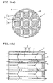
- the honeycomb filter used for such a purpose has a honeycomb structure having many through channels 13 partitioned by porous partition walls 12 running in the axial direction as shown in Figures 6(a) and 6(b) .
- One end of a part of the through channels 13a are plugged on one end face 16 and one end of the remaining through channels 13b are plugged on the other end face 15 (See JP-A-2001-269585 ).
- Gas to be treated flows into through channels 13a of which the end face 15 on the inlet port side is not plugged, but the end face 16 on the outlet port side is plugged, passes through the porous partition walls 12, moves to through channels 13b of which the end face 15 on the inlet port side is plugged, but the end face 16 on the outlet port side is not plugged, and discharged from the through channels 13b.
- the partition walls 12 serve as filter layers. Particulate matters such as soot in the gas are caught by the partition walls 12 and accumulate on the partition walls 12.
- WO 02/070106 discloses a honeycomb filter obtained by bonding a plurality of honeycomb segments, wherein each two adjacent segments are contacted with each other at a part of their side faces and wherein bonding material is provided between the side faces of the segments where there is no contact.
- a diesel particulate filter (DPF) used for purifying exhaust gas fromdiesel engines has particulatematters gradually accumulated in the filter as the use of the filter progresses. If left as is, the filter performance degrades. Therefore, when the particulate matters accumulate to some extent, the filter is heated to remove the deposited particulate matters by burning, thereby recovering the filter performance.
- solids such as ash and iron oxide which cannot be removed by combustion are gradually accumulated and clog the filter.
- conventional honeycomb filters have a configuration in which the through channels are plugged not only on the end face on the outlet port side of exhaust gas, but also on the end face on the inlet port side which is directly exposed to the exhaust gas. Therefore, such conventional honeycomb filters have a problem in thermal shock resistance due to heat expansion and the like of the plugging portions on the end face on the inlet port side. For this reason, it has been difficult to use such filters for purifying exhaust gas from gasoline engines discharging exhaust gas at a temperature higher than that of diesel engines in a temperature fluctuation range greater than that of diesel engines.
- particulate matters adhere to the plugging portions of through channels on the end face on the exhaust gas inlet port side of the honeycomb filters and deposit around the adhered particulate matters as a core, causing even the openings of the through channels of which the end face is not plugged on the exhaust gas inlet port side to clog. This causes another problem of rapidly increasing a pressure loss in the filter.
- a honeycomb filter assembly capable of using for exhaust gas purification, (1) to reduce a pressure loss, (2) to prevent clogging of the filter with solids that cannot be extinguished by combustion of ash, iron oxide, or the like, (3) to control the phenomenon in which particulate matters deposited in the through channels of the filter are discharged to the filter due to pulsation when the exhaust gas from the engine greatly pulsates, (4) to make it possible to use the filter as an exhaust gas purification filter for gasoline engines of which the exhaust gas temperature is higher than that of diesel engines and fluctuates within a fluctuation range wider than that of diesel engines, and (5) to avoid a rapid increase in the pressure loss in the filter due to clogging of openings of through channels on the end face on the exhaust gas inlet port side with deposited particulate matters.
- the present invention provides a honeycomb filter assembly comprising a first honeycomb filter which comprises a honeycomb structure having a large number of through channels extending in an axial direction between two axial end faces and separated by porous partition walls, wherein some of the through channels are plugged only at the same one of said two axial end faces, and a second honeycomb filter which comprises a honeycomb structure having a large number of through channels extending in an axial direction between two axial end faces and separated by porous partition walls, wherein some of the through channels are plugged at the same one of said two axial end faces and remaining through channels are plugged at the other end face of said two axial end faces; the first and second honeycomb filters being in contact with or joined to each other in respective plugging portions of through channels.
- the present invention further provides a method for manufacturing a honeycomb filter assembly according to the first aspect, which includes the steps of forming plugging portions in the through channels of both of said filters by filling one end of the through channels with a ceramic material, joining both filters by aligning the axial end faces containing the plugging portions and firing the resultant plug of the ceramic material so as to join the first and second honeycomb filters to each other thereby integrating the thus joined two honeycomb filters (second aspect of invention).
- the present invention further provides a method for manufacturing a honeycomb filter assembly according to the first aspect, which includes the steps of forming plugging portions in the through channels of said first honeycomb filter and said second honeycomb filter by filling one end of the through channels with a ceramic material and firing the resultant plug of ceramic material, wherein, after firing, the first and second honeycomb filters are joined to each other at specified plugging portions by aligning axial end faces, using a cement and firing again to integrate the thus joined two honeycomb filters.
- a method for manufacturing a honeycomb filter assembly according to the first aspect, which includes the steps of forming plugging portions in the through channels of said first honeycomb filter and said second honeycomb filter by filling one end of the through channels with a ceramic material and firing the resultant plug of ceramic material, wherein, after firing, the first and second honeycomb filters are joined to each other at specified plugging portions by aligning axial end faces, using a cement and firing again to integrate the thus joined two honeycomb filters.
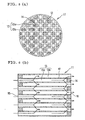
- FIG. 1 is a general illustration diagram of one embodiment of a honeycomb filter useful in the first aspect, wherein (a) is a plan view fromone end and (b) is a cross-sectional view.
- the honeycomb filter comprises a honeycomb structure having a large number of through channels 3 formed in the axial direction and partitioned by porous partition walls 2, wherein a part of large number of the through channels 3a is plugged only at one end face at the same side out of the two end faces.
- honeycomb structure As an example of the honeycomb structure which can be suitably used for this honeycomb filter, a honeycomb structure made of cordierite having an external diameter of 190.5 mm and a length of 203.2 mm, through channels with a square cross-sectional form (cell form), a cell pitch of 1.6 mm, and a partition wall thickness of 0.3 mm manufactured by extrusion molding can be given.
- through channels 13 are plugged on the end faces of both sides of the honeycomb structure (the inlet port side end face 15 and the outlet port side end face 16 of the gas to be treated) as shown in Figure 6 , with all the through channels 13 being plugged at either one of the ends, whereas in the honeycomb filter 1 of the first invention, specified through channels 3a among numerous through channels are plugged only at its end face 6 (which functions as the end face for the outlet port side of the gas to be treated during use) at the same side out of two end faces of the honeycomb structure, as mentioned above.
- the through channels 3a plugged at the one end face at the same side out of two end faces are present together with through channels 3b not plugged at any end face.
- the gas to be treated flowing into the through channels 3a, of which one end is plugged passes through the porous partition walls 2 functioning as a filter layer and is discharged outside after removal of particulate matters in the gas.
- the efficiency of capturing the particulate matters as the whole filter would decrease relatively, as compared with a conventional honeycomb filter.
- the pressure loss can be reduced as compared with a conventional honeycomb filter.
- This type of the filter is useful in the application in which the capturing efficiency is not required so severely.
- solids such as ash and iron oxide remaining in the unplugged through channels 3b without extinguishing after burning particulate matters deposited inside the filter are discharged outside by the pressure of the gas passing through the through channels 3b, clogging of the filter due to the solids hardly occurs.
- the honeycomb filter can be suitably used for the exhaust gas purification system in lean burn gasoline engines and direct-injection gasoline engines, as well as in diesel engines.
- gasoline engines discharge exhaust gas at a higher temperature and with greater fluctuation, as compared with diesel engines.
- the exhaust gas temperature of a diesel engine is about 600°C at most, whereas the exhaust gas temperature of a gasoline engine may reach 1000°C or more in the neighborhood of the engine.
- the honeycomb filter shown in Figure 1 has a configuration in which the plugging portions of through channels are provided only on the one end face at the same side out of two end faces, without plugging portions of through channels on the other end face located at the opposite side.
- This honeycomb filter can resist severe thermal shock by an exhaust gas temperature fluctuation in the exhaust gas inlet port side, even if it is used for a gasoline engine, by installing it in such a manner that the end face of the side having no plugging portion is used as an end face of the exhaust gas inlet port side. Accordingly, the honeycomb filter can be suitably used also in a diesel engine, even under the conditions that the temperature fluctuation of the exhaust gas is larger and the thermal shock is more severe.
- plugging portions 4 of the through channels are formed in a checkerwise pattern in Figure 1
- the configuration of the plugging portion is not limited to this pattern.
- through channels at one end face at the same side out of two end faces and through channels not plugged at any end face may be respectively arranged in line viewing from the end face side of the honeycomb structure.
- the configuration of the plugging portions of these through channels according to the cross-sectional form (cell form) of the through channels.
- the cell form is a quadrangle in the examples shown in the accompanying figures, a polygon such as a triangle or a hexagon, a circle, or a combination of different cell forms are acceptable.
- the cross-sectional form of the honeycomb structure In addition to a circle, any forms such as an ellipse, long circle, oval, approximate triangle, and approximate quadrangle are possible.
- the frontal area of the through channels needs not be the same in all through channels. It is possible to provide the through channels with different frontal areas.
- the honeycomb structure 1 has through channels 3c with a relatively large frontal area and through channels 3d with a relatively small frontal area.
- the material for the honeycomb structure is preferably a ceramic such as cordierite, alumina, mullite, aluminum titanate, titania, zirconia, siliconnitride, aluminum nitride, silicon carbide, or LAS (lithium aluminum silicate), a composite of two or more of these ceramics, a metal such as stainless steel or aluminum alloys, or an adsorbent such as activated carbon, silica gel, or zeolite.
- the same material is preferably used for the plugging portion 4 which plugs the end of through channels and for the honeycomb structure to make the coefficient of thermal expansion the same.
- Noble metals such as platinum (Pt), rhodium (Rh), and palladium (Pd) and non-noble metals such as copper, titania, vanadium, zeolite, and a perovskite-type catalyst may be carried on the surface of the partition walls and/or the surface of the pores inside the partition walls of the honeycomb structure to make it possible to treat hazardous components such as hydrocarbons (HC), carbon monoxide (CO), and nitrogen oxides (NOx) in exhaust gas or to accelerate burning of particulate matters deposited in the filter.
- hazardous components such as hydrocarbons (HC), carbon monoxide (CO), and nitrogen oxides (NOx)
- an oxidation catalyst having a function to process hydrocarbons, CO, and particulate matters such as Pt or Pd is used.
- a reduction catalyst such as Rh may also be carried to process NOx.
- the reduction catalyst may be covered with particulate matters or ash, physically obstructing NOx components from coming into contact with the catalyst.
- the reduction reaction may also be prevented if hydrocarbons are oxidized, since the hydrocarbons function also as a reducing agent.
- the oxidation catalyst and the reduction catalyst are carried on the honeycomb filter of the first invention, the oxidation catalyst is carried on the inside-pore surface of the partition walls partitioning the through channels plugged at one end at the same side out of two end faces and/or on the surface of the pores inside the partition walls, and the reduction catalyst is carried on the inside-pore surface of the partition walls partitioning the other through channels not plugged at any end face and/or on the surface of the pores inside the partition walls, whereby the co-existence of the oxidation catalyst and reduction catalyst within the same region can be basically avoided.
- hydrocarbons are present without being oxidized in the through channel not plugged at any end face, the hydrocarbons can function as a reducing agent.
- no sulfuric acid will be produced by oxidation of sulfur components in the through channel not plugged at any end face.
- exhaust gas passing through the through channel plugged at one end face at the same side out of the two end faces comes into the through channel not plugged at any end face, only a small amount of particulate matters accumulate on the partition wall surface of the through channel, whereby the particulate matters hardly cover the reduction catalyst and consequently the catalyst is seldom prevented from contacting NOx components.
- NOx components are mainly generated in the course of burning at a high temperature, a large amount of the Nox components are produced in the high engine load and high engine rotation region. Both the amount and the flow rate of exhaust gas increase when the NOx components are produced. Under these conditions, since the exhaust gas tends to flow selectively into the through channel not plugged at any end face, where ventilation resistance is relatively low, it is effective to dispose the reduction catalyst in the through channel not plugged at any end face. If the exhaust gas is heated to a high temperature, particulate matters burn themselves.
- the oxidation catalyst can be completely separated from the reduction catalyst if the catalyst components are carried only on the surface of the partition wall. However, if the catalyst components are carried on also inside the pores in the partition wall, the oxidation catalyst may be present together with the reduction catalyst inside the partition wall.
- a honeycomb filter can be accepted if designed as a whole in such a manner that the oxidation catalyst is a major component in the through channel plugged at one end face at the same side out of the two end faces, the reduction catalyst increases toward the through channel not plugged at any end face, and the reduction catalyst becomes a major component in the through channel not plugged at any end face.
- honeycomb filters When two or more honeycomb filters are used as in the case of the exhaust gas purification system discussed later, it is unnecessary to provide the same material characteristics such as the material of construction for each honeycomb, cell density, wall thickness, cell structure such as cell form, porosity, pore size, and pore distribution. Any optional honeycomb filters can be selected according to the use conditions.
- a method for manufacturing the honeycomb filter a method comprising forming a honeycomb structure by extrusion or the like, filling a predetermined through channel at one end face out of the two end faces of the honeycomb structure with a ceramic material in the form of a slurry or paste to form the plugging portions, and firing the resultant having the plugging portions is simple.
- firing is carried out using through channels being plugged only on one end face, a firing shrinkage difference is produced between the end face on which the through channels is plugged and the end face on which the through channels is unplugged. Defects in the products such as distortion, deforming, and cracks tend to generate due to imbalanced shrinkage.
- the plugging portions by filling the predetermined through channels not at either one end face, but at any end face of the honeycomb structure, fire the resultant in such a manner that the amount of shrinkage during firing may be approximately the same on both end faces, and removing one of the plugging portions of the through channels at a predetermined one end face out of the two end faces.
- the obtained honeycomb structure is cut on the center to produce two identical honeycomb filters.
- a slurry containing a reduction catalyst component is fed to open through channels from the other end face to cause the reduction catalyst component to be carried in the through channels.
- the end face on the side from which the slurry containing the oxidation catalyst component was fed is cut and removed together with the plugging portions of the through channels.
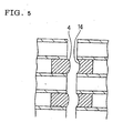
- the honeycomb filter assembly of the first aspect employs the honeycomb filter 1 shown in Figures 1 and 2 and the honeycomb filter 11 with a conventional configuration in combination as shown in Figure 3 , wherein the two filters are maintained in contact with each other by any means or integrated by joining to form one honeycomb filter with an objective of, for example, easy incorporation into a system.
- the first honeycomb filter 1 comprising a honeycomb structure having a large number of through channels formed in the axial direction and partitioned by porous partition walls, wherein specified through channels are plugged at one end face at the same side out of two end faces and a second honeycomb filter 11 comprising a honeycomb structure having a large number of through channels formed in the axial direction and partitioned by porous partition walls, wherein specified through channels are plugged at one end face at the same side out of the two end faces and the remaining through channels are plugged on the other end face (honeycomb filter with a conventional configuration as shown in Figure 6 ) are in contact with each other or joined in the plugging portions 4 and 14 of the respective through channels.
- the two filters 1 and 11 are caused to be in contact with each other or joined to become integrated in the plugging portions 4 and 14 of the respective through channels, as described above.
- a sufficient area for contact or joining to provide necessary strength can be secured if the plugging portions 4 and 14 are disposed so that the respective plugging portions are in contact with each other when the two filters are joined at one end face of them. Effects such as easy incorporation into an exhaust gas purification system and smooth gas flow between both filters can be obtained by causing the two honeycomb filters to become in contact with each other or joining them to integrate in this manner.
- the second aspect provides one embodiment of a method for manufacturing the honeycomb filter assembly of the first aspect.
- the method comprises, in the case in which the plugging portions 4 and 14 of the through channels of the first honeycomb filter 1 and the second honeycomb filter 11 are formed by filling the end of the through channels with a ceramic material and firing the ceramic material, joining the unfired plugging portions (the ceramic material filled in the end of the through channels) of the first honeycomb filter 1 and the second honeycomb filter 11 each other prior to firing and thereafter integrating the two honeycomb filters by firing. If the plugging portions of the through channels of both honeycomb filters are joined before firing in this manner, the two honeycomb filters can be integrated during subsequent firing without using cement or the like.
- a cement or the like may be used for joining the unfired plugging portions, whereby it is possible to integrate the two honeycomb filters more firmly.
- a cement or the like may be used for joining the unfired plugging portions, whereby it is possible to integrate the two honeycomb filters more firmly.
- it is possible to secure reliability of the joint by devising the type of cement used so that the thermal expansion differences can be mitigated.
- the third aspect provides another embodiment of a method for manufacturing the honeycomb filter assembly of the first aspect.
- the method comprises, in the case in which the plugging portions 4 and 14 of the through channels of the first honeycomb filter 1 and the second honeycomb filter 11 are formed by filling the end of the through channels with a ceramic material and firing the ceramic material, joining the plugging portions of the first honeycomb filter 1 and the second honeycomb filter 11 each other using cement after firing and thereafter again firing to integrate the two honeycomb filters.
- the first honeycomb filter 1 and the second honeycomb filter 11 each having the plugging portions already fired it is possible to integrate the two honeycomb filters easily and with a sufficient joining force.
- the catalyst component may be carried on either before or after joining the two honeycomb filters.
- the joining surface in the plugging portions 4 of either the first honeycomb filter 1 or the second honeycomb filter 11 convex and the joining surface of the other plugging portions 14 concave as shown in Figure 5 whereby the joining position of the two honeycomb filters can be easily determined and the joining force can increase.
- the joining position of the two honeycomb filters can also be easily determined by providing the plugging portions of either the first honeycomb filter or the second honeycomb filter with a pin and providing the other honeycomb filter with a hole that can engage the pin in the plugging portions.
- the exhaust gas pulsation can be adsorbed by any unplugged through channels of which ventilation resistance is relatively small, whereby it is possible to control discharge of particulate matters deposited in the through channels plugged at the one end face out of the two end faces to the back of the filter due to exhaust gas pulsation.
- honeycomb filter assembly of the present invention can be used as an exhaust gas purification filter for gasoline engines of which the exhaust gas temperature is higher than that of diesel engines and fluctuates within a fluctuation range wider than that of diesel engines.
- the resulting system can solve the problem of adhesion of particulate matters to the plugging portions of the through channels on the end face on the exhaust gas inlet port side of the honeycomb filters, resulting in deposition of particulate matters around the adhered particulate matters as a core and clogging of openings of the through channels not plugged at the end faces on the exhaust gas inlet port side, and eventually causing a rapid increase in the pressure loss in the filter.
Landscapes
- Chemical & Material Sciences (AREA)
- Engineering & Computer Science (AREA)
- Ceramic Engineering (AREA)
- Chemical Kinetics & Catalysis (AREA)
- Materials Engineering (AREA)
- Structural Engineering (AREA)
- Organic Chemistry (AREA)
- Combustion & Propulsion (AREA)
- Manufacturing & Machinery (AREA)
- Mechanical Engineering (AREA)
- Geometry (AREA)
- Physics & Mathematics (AREA)
- General Engineering & Computer Science (AREA)
- Health & Medical Sciences (AREA)
- Oil, Petroleum & Natural Gas (AREA)
- Environmental & Geological Engineering (AREA)
- Analytical Chemistry (AREA)
- General Chemical & Material Sciences (AREA)
- Toxicology (AREA)
- Biomedical Technology (AREA)
- Filtering Materials (AREA)
- Filtering Of Dispersed Particles In Gases (AREA)
- Processes For Solid Components From Exhaust (AREA)
- Catalysts (AREA)
- Exhaust Gas After Treatment (AREA)
- Exhaust Gas Treatment By Means Of Catalyst (AREA)
Claims (4)
- Wabenstrukturfilteranordnung (30), umfassend einen ersten Wabenstrukturfilter (1), der eine Wabenstruktur mit einer großen Anzahl an Durchgangskanälen umfasst, die sich in axialer Richtung zwischen zwei axialen Endflächen erstrecken und durch poröse Trennwände getrennt sind, wobei manche Durchgangskanäle nur an einer der beiden axialen Endflächen verschlossen sind, und einen zweiten Wabenstrukturfilter (11), der eine Wabenstruktur mit einer großen Anzahl an Durchgangskanälen umfasst, die sich in axialer Richtung zwischen zwei axialen Endflächen erstrecken und durch poröse Trennwände getrennt sind, wobei manche Durchgangskanäle an einer der beiden axialen Endflächen verschlossen sind und die anderen Durchgangskanäle an der anderen der beiden axialen Endflächen verschlossen sind; wobei der erste und der zweite Wabenstrukturfilter (1, 11) an den entsprechenden verschlossenen Abschnitten (4, 14) der Durchgangskanäle miteinander in Kontakt stehen oder verbunden sind.
- Verfahren zur Herstellung einer Wabenstrukturfilteranordnung (30) nach Anspruch 1, das folgende Schritte umfasst:das Ausbilden von verschlossenen Abschnitten (4, 14) in den Durchgangskanälen beider Filter (1, 11) durch das Befüllen eines Endes der Durchgangskanäle mit einem Keramikmaterial,das Verbinden beider Filter durch das fluchtende Ausrichten der axialen Endflächen, die die verschlossenen Abschnitte (4, 14) aufweisen, unddas Brennen des resultierenden Keramikmaterialverschlusses, um den ersten und den zweiten Wabenstrukturfilter (1, 11) miteinander zu verbinden, wodurch die beiden auf diese Weise verbundenen Wabenstrukturfilter zu einem Ganzen vereinigt werden.
- Verfahren zur Herstellung einer Wabenstrukturfilteranordnung (30) nach Anspruch 1, das folgende Schritte umfasst:das Ausbilden von verschlossenen Abschnitten (4, 14) in den Durchgangskanälen des ersten Wabenstrukturfilters (1) und des zweiten Wabenstrukturfilters (11) durch das Befüllen eines Endes der Durchgangskanäle mit einem Keramikmaterial und das Brennen des resultierenden Keramikmaterialverschlusses, wobei nach dem Brennen der erste und der zweite Wabenstrukturfilter (1, 11) an spezifischen verschlossenen Abschnitten (4, 14) durch das fluchtende Ausrichten der axialen Endflächen unter Verwendung eines Zements und durch erneutes Brennen, um die beiden auf diese Weise verbundenen Wabenstrukturfilter zu einem Ganzen zu vereinigen, miteinander verbunden sind.
- Verfahren nach Anspruch 3, worin eine Verbindungsoberfläche der verschlossenen Abschnitte (4, 14) des ersten Wabenstrukturfilters (1) oder des zweiten Wabenstrukturfilters (11) konvex ist und eine Verbindungsoberfläche der verschlossenen Abschnitte (4, 14) des anderen Filters der konvexen Oberfläche entsprechend konkav ist.
Applications Claiming Priority (3)
| Application Number | Priority Date | Filing Date | Title |
|---|---|---|---|
| JP2003039426 | 2003-02-18 | ||
| JP2003039426A JP4369141B2 (ja) | 2003-02-18 | 2003-02-18 | ハニカムフィルタ及び排ガス浄化システム |
| EP04250835A EP1450015B1 (de) | 2003-02-18 | 2004-02-17 | Wabenfilter und Abgasreinigungssystem |
Related Parent Applications (2)
| Application Number | Title | Priority Date | Filing Date |
|---|---|---|---|
| EP04250835A Division EP1450015B1 (de) | 2003-02-18 | 2004-02-17 | Wabenfilter und Abgasreinigungssystem |
| EP04250835.8 Division | 2004-02-17 |
Publications (3)
| Publication Number | Publication Date |
|---|---|
| EP1598534A2 EP1598534A2 (de) | 2005-11-23 |
| EP1598534A3 EP1598534A3 (de) | 2005-12-14 |
| EP1598534B1 true EP1598534B1 (de) | 2010-04-14 |
Family
ID=32732911
Family Applications (2)
| Application Number | Title | Priority Date | Filing Date |
|---|---|---|---|
| EP05017556A Expired - Lifetime EP1598534B1 (de) | 2003-02-18 | 2004-02-17 | Wabenfilter und Abgasreinigungssystem |
| EP04250835A Expired - Lifetime EP1450015B1 (de) | 2003-02-18 | 2004-02-17 | Wabenfilter und Abgasreinigungssystem |
Family Applications After (1)
| Application Number | Title | Priority Date | Filing Date |
|---|---|---|---|
| EP04250835A Expired - Lifetime EP1450015B1 (de) | 2003-02-18 | 2004-02-17 | Wabenfilter und Abgasreinigungssystem |
Country Status (4)
| Country | Link |
|---|---|
| US (2) | US7618596B2 (de) |
| EP (2) | EP1598534B1 (de) |
| JP (1) | JP4369141B2 (de) |
| DE (2) | DE602004014659D1 (de) |
Cited By (1)
| Publication number | Priority date | Publication date | Assignee | Title |
|---|---|---|---|---|
| US11459924B2 (en) | 2014-09-03 | 2022-10-04 | Corning Incorporated | Honeycomb body having layered plugs and method of making the same |
Families Citing this family (84)
| Publication number | Priority date | Publication date | Assignee | Title |
|---|---|---|---|---|
| CN1322909C (zh) * | 2002-09-13 | 2007-06-27 | 揖斐电株式会社 | 蜂窝状结构体 |
| JP2004261664A (ja) * | 2003-02-28 | 2004-09-24 | Ngk Insulators Ltd | ハニカム構造体及びハニカム構造体押出し成形用口金 |
| JP3896998B2 (ja) | 2003-07-08 | 2007-03-22 | トヨタ自動車株式会社 | 内燃機関の排気浄化装置 |
| JP4569865B2 (ja) * | 2003-07-14 | 2010-10-27 | 日立金属株式会社 | セラミックハニカムフィルタ及びその製造方法 |
| JP4513063B2 (ja) * | 2004-11-30 | 2010-07-28 | 日立金属株式会社 | ハニカムフィルタ |
| JP2006150309A (ja) * | 2004-12-01 | 2006-06-15 | Hitachi Metals Ltd | ハニカムフィルタ |
| JP4528153B2 (ja) | 2005-02-23 | 2010-08-18 | 日本碍子株式会社 | 目封止ハニカム構造体の製造方法 |
| WO2006091136A1 (en) * | 2005-02-24 | 2006-08-31 | Volvo Technology Corporation | Arrangement and method for removal of particulates in a gas flow |
| JP4848662B2 (ja) * | 2005-04-07 | 2011-12-28 | パナソニック株式会社 | 排ガス浄化材の使用方法 |
| JP4792792B2 (ja) * | 2005-04-07 | 2011-10-12 | パナソニック株式会社 | 排ガス浄化装置 |
| US20060251548A1 (en) | 2005-05-06 | 2006-11-09 | Willey Ray L | Exhaust aftertreatment device |
| US7867598B2 (en) * | 2005-08-31 | 2011-01-11 | Ngk Insulators, Ltd. | Honeycomb structure and honeycomb catalytic body |
| DE102005045015A1 (de) * | 2005-09-21 | 2007-03-29 | Robert Bosch Gmbh | Filterelement und Rußfilter mit verbesserter Thermoschockbeständigkeit |
| JP4600826B2 (ja) * | 2005-10-18 | 2010-12-22 | 日立金属株式会社 | セラミックハニカムフィルタ |
| EP1957184A1 (de) * | 2005-12-05 | 2008-08-20 | Eidgenössische Materialprüfungs- und Forschungsanstalt Empa | Diffusor für abgasreinigungssysteme |
| JP2007222858A (ja) * | 2006-01-27 | 2007-09-06 | Hitachi Metals Ltd | セラミックハニカムフィルタ |
| CN101384330B (zh) * | 2006-02-17 | 2011-04-13 | 日立金属株式会社 | 陶瓷蜂窝过滤器及排放气体净化装置 |
| JP5006064B2 (ja) * | 2006-03-29 | 2012-08-22 | 日本碍子株式会社 | ハニカム構造体 |
| JP4619976B2 (ja) * | 2006-03-30 | 2011-01-26 | 日本碍子株式会社 | プラズマリアクタ |
| DE202006007876U1 (de) * | 2006-05-15 | 2007-09-20 | Bauer Technologies Gmbh | Optimierung von zellulären Strukturen, insbesondere für die Abgasreinigung von Verbrennungsaggregaten und andere Anwendungsbereiche |
| DE102006026161A1 (de) * | 2006-05-23 | 2007-11-29 | Robert Bosch Gmbh | Filtereinrichtung, insbesondere für ein Abgassystem einer Brennkraftmaschine |
| WO2008011146A1 (en) * | 2006-07-21 | 2008-01-24 | Dow Global Technologies Inc. | Improved zone catalyzed soot filter |
| EP2058042B2 (de) * | 2006-08-30 | 2017-05-03 | Hitachi Metals, Ltd. | Keramikwabenfilter |
| DE102006048045A1 (de) * | 2006-10-11 | 2008-04-17 | Daimler Ag | Abgasreinigungsanlage für eine Brennkraftmaschine |
| US7491373B2 (en) * | 2006-11-15 | 2009-02-17 | Corning Incorporated | Flow-through honeycomb substrate and exhaust after treatment system and method |
| US20080120968A1 (en) * | 2006-11-29 | 2008-05-29 | Douglas Munroe Beall | Partial wall-flow filter and diesel exhaust system and method |
| WO2008113507A1 (de) * | 2007-03-16 | 2008-09-25 | Elringklinger Ag | Dieselpartikelfilter-bauteil |
| JP5150132B2 (ja) * | 2007-04-27 | 2013-02-20 | 日本碍子株式会社 | ハニカムフィルタシステム |
| JP2009000647A (ja) * | 2007-06-22 | 2009-01-08 | Tokyo Yogyo Co Ltd | 排ガス浄化用フィルタ |
| US8166751B2 (en) * | 2007-07-31 | 2012-05-01 | Caterpillar Inc. | Particulate filter |
| US7806956B2 (en) * | 2007-08-09 | 2010-10-05 | Cummins Filtration Ip, Inc. | Tuning particulate filter performance through selective plugging and use of multiple particulate filters to reduce emissions and improve thermal robustness |
| US20090056546A1 (en) * | 2007-08-31 | 2009-03-05 | Timothy Adam Bazyn | Partial flow exhaust filter |
| US8105417B2 (en) * | 2007-09-14 | 2012-01-31 | GM Global Technology Operations LLC | Face crack reduction strategy for particulate filters |
| US9828298B2 (en) * | 2007-11-30 | 2017-11-28 | Corning Incorporated | Cement compositions for applying to honeycomb bodies |
| JP2009154124A (ja) * | 2007-12-27 | 2009-07-16 | Ngk Insulators Ltd | 部分目封止レスdpf |
| WO2009101682A1 (ja) | 2008-02-13 | 2009-08-20 | Ibiden Co., Ltd. | ハニカム構造体、排ガス浄化装置、及び、ハニカム構造体の製造方法 |
| WO2009101683A1 (ja) * | 2008-02-13 | 2009-08-20 | Ibiden Co., Ltd. | ハニカム構造体の製造方法 |
| CN102046263A (zh) * | 2008-05-29 | 2011-05-04 | 康宁股份有限公司 | 部分壁流式过滤器和方法 |
| US20100154392A1 (en) * | 2008-12-18 | 2010-06-24 | Caterpillar Inc. | Adjusting nitrogen oxide ratios in exhaust gas |
| JP5409070B2 (ja) | 2009-03-24 | 2014-02-05 | 日本碍子株式会社 | 排ガス浄化装置の製造方法及び排ガス浄化装置 |
| JP5476011B2 (ja) * | 2009-03-24 | 2014-04-23 | 日本碍子株式会社 | 排ガス浄化装置 |
| US8444752B2 (en) * | 2009-08-31 | 2013-05-21 | Corning Incorporated | Particulate filters and methods of filtering particulate matter |
| JP5548470B2 (ja) * | 2010-02-16 | 2014-07-16 | 日本碍子株式会社 | ハニカム触媒体 |
| JP5563844B2 (ja) * | 2010-02-16 | 2014-07-30 | 日本碍子株式会社 | 排気ガス浄化装置 |
| US8444730B2 (en) * | 2010-09-27 | 2013-05-21 | Ford Global Technologies, Llc | Even-loading DPF and regeneration thereof |
| SE535454C2 (sv) * | 2010-11-16 | 2012-08-14 | Scania Cv Ab | Partikelfilter för ett avgassystem hos en förbränningsmotor |
| KR20150015444A (ko) * | 2012-04-23 | 2015-02-10 | 다우 글로벌 테크놀로지스 엘엘씨 | 축방향으로 섹션화된 세라믹 허니콤 조립체 |
| WO2013182327A1 (de) * | 2012-06-04 | 2013-12-12 | Hjs Emission Technology Gmbh & Co. Kg | Als teilfilter ausgeführter partikelfilter |
| WO2013186922A1 (ja) | 2012-06-15 | 2013-12-19 | イビデン株式会社 | ハニカムフィルタ |
| WO2013186923A1 (ja) | 2012-06-15 | 2013-12-19 | イビデン株式会社 | ハニカムフィルタ |
| EP2698190B1 (de) * | 2012-08-13 | 2018-06-27 | NGK Insulators, Ltd. | Abgedichtete Wabenstruktur |
| PL2698188T3 (pl) * | 2012-08-17 | 2018-05-30 | Pall Corporation | Moduł filtra katalitycznego i zawierający go układ filtra katalitycznego |
| WO2014054159A1 (ja) | 2012-10-04 | 2014-04-10 | イビデン株式会社 | ハニカムフィルタ |
| US9757675B2 (en) * | 2013-01-29 | 2017-09-12 | Corning Incorporated | Partial wall-flow filter and method |
| JP2014148924A (ja) * | 2013-01-31 | 2014-08-21 | Ngk Insulators Ltd | 排ガス浄化装置 |
| US20140238242A1 (en) * | 2013-02-28 | 2014-08-28 | Corning Incorporated | Ceramic partial wall-flow filter with low deep bed |
| JP5972816B2 (ja) * | 2013-03-22 | 2016-08-17 | 日本碍子株式会社 | ハニカム構造体 |
| JP6239303B2 (ja) | 2013-07-31 | 2017-11-29 | イビデン株式会社 | ハニカムフィルタ |
| JP6239305B2 (ja) * | 2013-07-31 | 2017-11-29 | イビデン株式会社 | ハニカムフィルタ |
| JP6239307B2 (ja) | 2013-07-31 | 2017-11-29 | イビデン株式会社 | ハニカムフィルタ |
| JP6239306B2 (ja) | 2013-07-31 | 2017-11-29 | イビデン株式会社 | ハニカムフィルタ |
| JP6239304B2 (ja) | 2013-07-31 | 2017-11-29 | イビデン株式会社 | ハニカムフィルタ |
| JP6267452B2 (ja) * | 2013-07-31 | 2018-01-24 | イビデン株式会社 | ハニカムフィルタ |
| GB2520776A (en) * | 2013-12-02 | 2015-06-03 | Johnson Matthey Plc | Wall-flow filter comprising catalytic washcoat |
| US9981216B2 (en) * | 2013-12-02 | 2018-05-29 | Cataler Corporation | Exhaust gas purification device and particulate filter |
| JP6492495B2 (ja) * | 2014-01-27 | 2019-04-03 | 株式会社デンソー | 排ガス浄化フィルタ及びその製造方法 |
| CN104949212B (zh) * | 2014-03-28 | 2017-11-14 | Lg电子株式会社 | 空气净化器 |
| CN104949213B (zh) | 2014-03-28 | 2017-09-29 | Lg电子株式会社 | 空气净化器 |
| JP6285247B2 (ja) * | 2014-03-31 | 2018-02-28 | 日本碍子株式会社 | ハニカム構造体 |
| JP6365319B2 (ja) * | 2015-01-20 | 2018-08-01 | 株式会社デンソー | Pmセンサの異常診断装置 |
| JP2016160847A (ja) * | 2015-03-03 | 2016-09-05 | 株式会社デンソー | 排気浄化装置 |
| CN104819034B (zh) * | 2015-04-22 | 2017-08-04 | 江苏大学 | 一种柴油机egr系统可重复利用脱硫颗粒过滤装置 |
| JP6431823B2 (ja) | 2015-07-13 | 2018-11-28 | 株式会社Soken | 排ガス浄化フィルタ |
| JP6578938B2 (ja) * | 2015-12-25 | 2019-09-25 | 株式会社デンソー | 排ガスフィルタ |
| JP6622128B2 (ja) * | 2016-03-25 | 2019-12-18 | 日本碍子株式会社 | ハニカム構造体 |
| JP2017227127A (ja) * | 2016-06-20 | 2017-12-28 | いすゞ自動車株式会社 | フィルタ装置 |
| EP3718974B1 (de) | 2018-02-02 | 2024-04-03 | Proterial, Ltd. | Keramisches filtermodul zur wasserbehandlung |
| JP2019178635A (ja) * | 2018-03-30 | 2019-10-17 | 日本碍子株式会社 | ハニカム構造体 |
| JP7049156B2 (ja) * | 2018-03-30 | 2022-04-06 | 日本碍子株式会社 | ハニカムフィルタ |
| SE1850373A1 (en) * | 2018-04-04 | 2019-10-05 | Nibe Ab | Method for providing clean residential comfort heating |
| JP7329950B2 (ja) * | 2019-03-29 | 2023-08-21 | 日本碍子株式会社 | パティキュレートフィルタ及びキャニング構造体 |
| CN111156069A (zh) * | 2020-02-14 | 2020-05-15 | 威海鸣川汽车技术有限公司 | 吸附网及尾气颗粒物捕集装置 |
| CN111664718B (zh) * | 2020-06-20 | 2022-02-18 | 信丰县包钢新利稀土有限责任公司 | 一种可回收利用钕铁硼废料焙烧窑炉余热的装置及方法 |
| CN114837773B (zh) * | 2022-05-27 | 2023-07-28 | 奇瑞汽车股份有限公司 | 颗粒捕集装置及车辆 |
Family Cites Families (23)
| Publication number | Priority date | Publication date | Assignee | Title |
|---|---|---|---|---|
| US4416676A (en) * | 1982-02-22 | 1983-11-22 | Corning Glass Works | Honeycomb filter and method of making it |
| US4417908A (en) * | 1982-02-22 | 1983-11-29 | Corning Glass Works | Honeycomb filter and method of making it |
| JPS5928010A (ja) * | 1982-08-05 | 1984-02-14 | Nippon Denso Co Ltd | 排気ガス浄化用構造物 |
| EP0225402A1 (de) | 1985-11-05 | 1987-06-16 | Nippondenso Co., Ltd. | Poröse Keramikstruktur |
| JP3130587B2 (ja) | 1991-09-17 | 2001-01-31 | イビデン株式会社 | 排気ガス浄化装置のハニカムフィルタ |
| JPH0647619A (ja) | 1992-01-06 | 1994-02-22 | Mitsubishi Materials Corp | サブランド付きリーマ |
| JP3387290B2 (ja) | 1995-10-02 | 2003-03-17 | トヨタ自動車株式会社 | 排ガス浄化用フィルター |
| JPH1099626A (ja) * | 1996-09-30 | 1998-04-21 | Ibiden Co Ltd | ハニカムフィルタ及びその製造方法 |
| JP2002537965A (ja) | 1999-02-26 | 2002-11-12 | ジョンソン、マッセイ、パブリック、リミテッド、カンパニー | モノリス触媒/フィルタ装置 |
| JP2001205108A (ja) | 2000-01-24 | 2001-07-31 | Toyota Motor Corp | パティキュレートフィルター |
| US6776814B2 (en) * | 2000-03-09 | 2004-08-17 | Fleetguard, Inc. | Dual section exhaust aftertreatment filter and method |
| JP3756721B2 (ja) | 2000-03-24 | 2006-03-15 | 日本碍子株式会社 | 排ガス浄化用フィルター |
| JP4471452B2 (ja) * | 2000-05-29 | 2010-06-02 | 日本碍子株式会社 | フィルターエレメントの製造方法 |
| JP2002004844A (ja) | 2000-06-22 | 2002-01-09 | Honda Motor Co Ltd | ディーゼルエンジン用排気浄化装置 |
| US6673414B2 (en) | 2000-12-20 | 2004-01-06 | Corning Incorporated | Diesel particulate filters |
| JP2002306915A (ja) * | 2001-02-09 | 2002-10-22 | Denso Corp | ハニカム構造体 |
| JP4404497B2 (ja) * | 2001-03-01 | 2010-01-27 | 日本碍子株式会社 | ハニカムフィルター、及びその製造方法 |
| JP3624892B2 (ja) * | 2001-03-29 | 2005-03-02 | トヨタ自動車株式会社 | 内燃機関の排気浄化装置 |
| JP4423818B2 (ja) | 2001-06-19 | 2010-03-03 | いすゞ自動車株式会社 | 排気ガス浄化装置 |
| JP2003035126A (ja) | 2001-07-24 | 2003-02-07 | Mitsubishi Motors Corp | ディーゼルエンジンの排気浄化装置 |
| US7090714B2 (en) * | 2002-06-17 | 2006-08-15 | Hitachi Metals, Ltd. | Ceramic honeycomb filter |
| US7189375B2 (en) * | 2002-09-16 | 2007-03-13 | Delphi Technologies, Inc. | Exhaust treatment device |
| JP3942086B2 (ja) | 2002-09-20 | 2007-07-11 | 日野自動車株式会社 | パティキュレートフィルタ |
-
2003
- 2003-02-18 JP JP2003039426A patent/JP4369141B2/ja not_active Expired - Lifetime
-
2004
- 2004-02-17 EP EP05017556A patent/EP1598534B1/de not_active Expired - Lifetime
- 2004-02-17 EP EP04250835A patent/EP1450015B1/de not_active Expired - Lifetime
- 2004-02-17 DE DE602004014659T patent/DE602004014659D1/de not_active Expired - Lifetime
- 2004-02-17 US US10/778,051 patent/US7618596B2/en not_active Expired - Lifetime
- 2004-02-17 DE DE602004026554T patent/DE602004026554D1/de not_active Expired - Lifetime
-
2009
- 2009-05-08 US US12/453,362 patent/US20090226348A1/en not_active Abandoned
Cited By (1)
| Publication number | Priority date | Publication date | Assignee | Title |
|---|---|---|---|---|
| US11459924B2 (en) | 2014-09-03 | 2022-10-04 | Corning Incorporated | Honeycomb body having layered plugs and method of making the same |
Also Published As
| Publication number | Publication date |
|---|---|
| US20090226348A1 (en) | 2009-09-10 |
| JP2004251137A (ja) | 2004-09-09 |
| DE602004014659D1 (de) | 2008-08-14 |
| EP1598534A3 (de) | 2005-12-14 |
| US20040161373A1 (en) | 2004-08-19 |
| EP1598534A2 (de) | 2005-11-23 |
| JP4369141B2 (ja) | 2009-11-18 |
| EP1450015A1 (de) | 2004-08-25 |
| EP1450015B1 (de) | 2008-07-02 |
| DE602004026554D1 (de) | 2010-05-27 |
| US7618596B2 (en) | 2009-11-17 |
Similar Documents
| Publication | Publication Date | Title |
|---|---|---|
| EP1598534B1 (de) | Wabenfilter und Abgasreinigungssystem | |
| KR100874398B1 (ko) | 허니컴 구조체 | |
| EP1371826B1 (de) | Katalytischer Filter zum Reinigen von Abgasen | |
| US7316722B2 (en) | Honeycomb structure | |
| JP6140509B2 (ja) | ウォールフロー型排ガス浄化フィルタ | |
| US7559967B2 (en) | Honeycomb filter | |
| JP3862458B2 (ja) | ハニカム構造体 | |
| CN101801499B (zh) | 排气后处理过滤器和包含其的排气后处理系统 | |
| EP1704308B1 (de) | Abgassystem mit partikelfilter für einen magermotor | |
| JP4249489B2 (ja) | 内燃焼エンジンの排気ガスに含まれる粒子を濾過する濾過体 | |
| EP1880763B1 (de) | Wabenkörperartiger Filter, seine Herstellung, und Abgasreinigungsvorrichtung mit demselben | |
| EP1870573A1 (de) | Dieselpartikelfilter mit verbesserter Hitzebeständigkeit | |
| EP1601440B1 (de) | Verfahren zum filtern von abgasteilchen | |
| WO2007074808A1 (ja) | ハニカム構造体及びその製造方法 | |
| JP4767491B2 (ja) | ハニカム構造体 | |
| JP4426381B2 (ja) | ハニカム構造体及びその製造方法 | |
| US8137637B2 (en) | Particulate filter and method of making | |
| JP4285342B2 (ja) | 排ガス浄化フィルタの製造方法 | |
| JP4513063B2 (ja) | ハニカムフィルタ | |
| JP2006007100A (ja) | 排ガス浄化フィルタ | |
| KR100587136B1 (ko) | 디젤엔진용 필터촉매구조체 | |
| JP2006334452A (ja) | セラミックハニカムフィルタ | |
| JP2009275554A (ja) | 排ガス浄化装置 | |
| KR100636051B1 (ko) | 디젤엔진용 미립자포집 필터구조체 | |
| WO2014178632A1 (ko) | 가솔린엔진 배기가스 정화용 촉매시스템 |
Legal Events
| Date | Code | Title | Description |
|---|---|---|---|
| PUAI | Public reference made under article 153(3) epc to a published international application that has entered the european phase |
Free format text: ORIGINAL CODE: 0009012 |
|
| PUAL | Search report despatched |
Free format text: ORIGINAL CODE: 0009013 |
|
| AC | Divisional application: reference to earlier application |
Ref document number: 1450015 Country of ref document: EP Kind code of ref document: P |
|
| AK | Designated contracting states |
Kind code of ref document: A2 Designated state(s): AT BE BG CH CY CZ DE DK EE ES FI FR GB GR HU IE IT LI LU MC NL PT RO SE SI SK TR |
|
| AX | Request for extension of the european patent |
Extension state: AL LT LV MK |
|
| AK | Designated contracting states |
Kind code of ref document: A3 Designated state(s): AT BE BG CH CY CZ DE DK EE ES FI FR GB GR HU IE IT LI LU MC NL PT RO SE SI SK TR |
|
| AX | Request for extension of the european patent |
Extension state: AL LT LV MK |
|
| 17P | Request for examination filed |
Effective date: 20060419 |
|
| AKX | Designation fees paid |
Designated state(s): DE FR |
|
| 17Q | First examination report despatched |
Effective date: 20061016 |
|
| GRAP | Despatch of communication of intention to grant a patent |
Free format text: ORIGINAL CODE: EPIDOSNIGR1 |
|
| GRAS | Grant fee paid |
Free format text: ORIGINAL CODE: EPIDOSNIGR3 |
|
| GRAA | (expected) grant |
Free format text: ORIGINAL CODE: 0009210 |
|
| AC | Divisional application: reference to earlier application |
Ref document number: 1450015 Country of ref document: EP Kind code of ref document: P |
|
| AK | Designated contracting states |
Kind code of ref document: B1 Designated state(s): DE FR |
|
| REF | Corresponds to: |
Ref document number: 602004026554 Country of ref document: DE Date of ref document: 20100527 Kind code of ref document: P |
|
| PLBE | No opposition filed within time limit |
Free format text: ORIGINAL CODE: 0009261 |
|
| STAA | Information on the status of an ep patent application or granted ep patent |
Free format text: STATUS: NO OPPOSITION FILED WITHIN TIME LIMIT |
|
| 26N | No opposition filed |
Effective date: 20110117 |
|
| REG | Reference to a national code |
Ref country code: FR Ref legal event code: PLFP Year of fee payment: 13 |
|
| REG | Reference to a national code |
Ref country code: FR Ref legal event code: PLFP Year of fee payment: 14 |
|
| PGFP | Annual fee paid to national office [announced via postgrant information from national office to epo] |
Ref country code: FR Payment date: 20170112 Year of fee payment: 14 |
|
| REG | Reference to a national code |
Ref country code: FR Ref legal event code: ST Effective date: 20181031 |
|
| PG25 | Lapsed in a contracting state [announced via postgrant information from national office to epo] |
Ref country code: FR Free format text: LAPSE BECAUSE OF NON-PAYMENT OF DUE FEES Effective date: 20180228 |
|
| PGFP | Annual fee paid to national office [announced via postgrant information from national office to epo] |
Ref country code: DE Payment date: 20221229 Year of fee payment: 20 |
|
| REG | Reference to a national code |
Ref country code: DE Ref legal event code: R071 Ref document number: 602004026554 Country of ref document: DE |