EP1586488A1 - Elektrische Kraftfahrzeugverbindungsdose - Google Patents
Elektrische Kraftfahrzeugverbindungsdose Download PDFInfo
- Publication number
- EP1586488A1 EP1586488A1 EP05013808A EP05013808A EP1586488A1 EP 1586488 A1 EP1586488 A1 EP 1586488A1 EP 05013808 A EP05013808 A EP 05013808A EP 05013808 A EP05013808 A EP 05013808A EP 1586488 A1 EP1586488 A1 EP 1586488A1
- Authority
- EP
- European Patent Office
- Prior art keywords
- circuit
- conductors
- electrical
- bus bars
- flexible
- Prior art date
- Legal status (The legal status is an assumption and is not a legal conclusion. Google has not performed a legal analysis and makes no representation as to the accuracy of the status listed.)
- Withdrawn
Links
- 239000004020 conductor Substances 0.000 claims abstract description 150
- 239000000758 substrate Substances 0.000 claims abstract description 127
- 238000009413 insulation Methods 0.000 claims abstract description 119
- 238000003466 welding Methods 0.000 claims abstract description 26
- 230000004308 accommodation Effects 0.000 claims description 41
- 239000012774 insulation material Substances 0.000 claims description 14
- 238000000034 method Methods 0.000 claims description 12
- 239000000463 material Substances 0.000 claims description 7
- 238000005452 bending Methods 0.000 claims description 5
- 238000005476 soldering Methods 0.000 claims description 4
- RYGMFSIKBFXOCR-UHFFFAOYSA-N Copper Chemical compound [Cu] RYGMFSIKBFXOCR-UHFFFAOYSA-N 0.000 claims description 3
- 229910052802 copper Inorganic materials 0.000 claims description 3
- 239000010949 copper Substances 0.000 claims description 3
- 238000000465 moulding Methods 0.000 claims description 2
- 230000000694 effects Effects 0.000 claims 1
- 239000010410 layer Substances 0.000 description 33
- 238000010276 construction Methods 0.000 description 19
- 239000002184 metal Substances 0.000 description 18
- 229910052751 metal Inorganic materials 0.000 description 18
- 230000004075 alteration Effects 0.000 description 10
- 238000004080 punching Methods 0.000 description 7
- 238000004519 manufacturing process Methods 0.000 description 6
- 239000011248 coating agent Substances 0.000 description 5
- 238000000576 coating method Methods 0.000 description 5
- 238000010586 diagram Methods 0.000 description 4
- 239000011347 resin Substances 0.000 description 4
- 229920005989 resin Polymers 0.000 description 4
- 230000002349 favourable effect Effects 0.000 description 2
- 230000004048 modification Effects 0.000 description 2
- 238000012986 modification Methods 0.000 description 2
- 239000002991 molded plastic Substances 0.000 description 2
- 238000003825 pressing Methods 0.000 description 2
- 238000003780 insertion Methods 0.000 description 1
- 230000037431 insertion Effects 0.000 description 1
- 230000002452 interceptive effect Effects 0.000 description 1
- 238000005192 partition Methods 0.000 description 1
- 239000004033 plastic Substances 0.000 description 1
- 229920003023 plastic Polymers 0.000 description 1
- 239000002356 single layer Substances 0.000 description 1
- 229910000679 solder Inorganic materials 0.000 description 1
- 230000008646 thermal stress Effects 0.000 description 1
Images


Classifications
-
- B—PERFORMING OPERATIONS; TRANSPORTING
- B60—VEHICLES IN GENERAL
- B60R—VEHICLES, VEHICLE FITTINGS, OR VEHICLE PARTS, NOT OTHERWISE PROVIDED FOR
- B60R16/00—Electric or fluid circuits specially adapted for vehicles and not otherwise provided for; Arrangement of elements of electric or fluid circuits specially adapted for vehicles and not otherwise provided for
- B60R16/02—Electric or fluid circuits specially adapted for vehicles and not otherwise provided for; Arrangement of elements of electric or fluid circuits specially adapted for vehicles and not otherwise provided for electric constitutive elements
- B60R16/023—Electric or fluid circuits specially adapted for vehicles and not otherwise provided for; Arrangement of elements of electric or fluid circuits specially adapted for vehicles and not otherwise provided for electric constitutive elements for transmission of signals between vehicle parts or subsystems
- B60R16/0238—Electrical distribution centers
-
- B—PERFORMING OPERATIONS; TRANSPORTING
- B60—VEHICLES IN GENERAL
- B60R—VEHICLES, VEHICLE FITTINGS, OR VEHICLE PARTS, NOT OTHERWISE PROVIDED FOR
- B60R16/00—Electric or fluid circuits specially adapted for vehicles and not otherwise provided for; Arrangement of elements of electric or fluid circuits specially adapted for vehicles and not otherwise provided for
- B60R16/02—Electric or fluid circuits specially adapted for vehicles and not otherwise provided for; Arrangement of elements of electric or fluid circuits specially adapted for vehicles and not otherwise provided for electric constitutive elements
- B60R16/023—Electric or fluid circuits specially adapted for vehicles and not otherwise provided for; Arrangement of elements of electric or fluid circuits specially adapted for vehicles and not otherwise provided for electric constitutive elements for transmission of signals between vehicle parts or subsystems
- B60R16/0239—Electronic boxes
-
- H—ELECTRICITY
- H05—ELECTRIC TECHNIQUES NOT OTHERWISE PROVIDED FOR
- H05K—PRINTED CIRCUITS; CASINGS OR CONSTRUCTIONAL DETAILS OF ELECTRIC APPARATUS; MANUFACTURE OF ASSEMBLAGES OF ELECTRICAL COMPONENTS
- H05K1/00—Printed circuits
- H05K1/02—Details
- H05K1/0286—Programmable, customizable or modifiable circuits
- H05K1/0287—Programmable, customizable or modifiable circuits having an universal lay-out, e.g. pad or land grid patterns or mesh patterns
- H05K1/0289—Programmable, customizable or modifiable circuits having an universal lay-out, e.g. pad or land grid patterns or mesh patterns having a matrix lay-out, i.e. having selectively interconnectable sets of X-conductors and Y-conductors in different planes
-
- H—ELECTRICITY
- H05—ELECTRIC TECHNIQUES NOT OTHERWISE PROVIDED FOR
- H05K—PRINTED CIRCUITS; CASINGS OR CONSTRUCTIONAL DETAILS OF ELECTRIC APPARATUS; MANUFACTURE OF ASSEMBLAGES OF ELECTRICAL COMPONENTS
- H05K7/00—Constructional details common to different types of electric apparatus
- H05K7/02—Arrangements of circuit components or wiring on supporting structure
- H05K7/026—Multiple connections subassemblies
-
- H—ELECTRICITY
- H05—ELECTRIC TECHNIQUES NOT OTHERWISE PROVIDED FOR
- H05K—PRINTED CIRCUITS; CASINGS OR CONSTRUCTIONAL DETAILS OF ELECTRIC APPARATUS; MANUFACTURE OF ASSEMBLAGES OF ELECTRICAL COMPONENTS
- H05K2201/00—Indexing scheme relating to printed circuits covered by H05K1/00
- H05K2201/03—Conductive materials
- H05K2201/0332—Structure of the conductor
- H05K2201/0335—Layered conductors or foils
- H05K2201/0352—Differences between the conductors of different layers of a multilayer
-
- H—ELECTRICITY
- H05—ELECTRIC TECHNIQUES NOT OTHERWISE PROVIDED FOR
- H05K—PRINTED CIRCUITS; CASINGS OR CONSTRUCTIONAL DETAILS OF ELECTRIC APPARATUS; MANUFACTURE OF ASSEMBLAGES OF ELECTRICAL COMPONENTS
- H05K2201/00—Indexing scheme relating to printed circuits covered by H05K1/00
- H05K2201/10—Details of components or other objects attached to or integrated in a printed circuit board
- H05K2201/10227—Other objects, e.g. metallic pieces
- H05K2201/10272—Busbars, i.e. thick metal bars mounted on the printed circuit board [PCB] as high-current conductors
-
- Y—GENERAL TAGGING OF NEW TECHNOLOGICAL DEVELOPMENTS; GENERAL TAGGING OF CROSS-SECTIONAL TECHNOLOGIES SPANNING OVER SEVERAL SECTIONS OF THE IPC; TECHNICAL SUBJECTS COVERED BY FORMER USPC CROSS-REFERENCE ART COLLECTIONS [XRACs] AND DIGESTS
- Y10—TECHNICAL SUBJECTS COVERED BY FORMER USPC
- Y10T—TECHNICAL SUBJECTS COVERED BY FORMER US CLASSIFICATION
- Y10T29/00—Metal working
- Y10T29/49—Method of mechanical manufacture
- Y10T29/49002—Electrical device making
- Y10T29/49117—Conductor or circuit manufacturing
- Y10T29/49124—On flat or curved insulated base, e.g., printed circuit, etc.
- Y10T29/4913—Assembling to base an electrical component, e.g., capacitor, etc.
-
- Y—GENERAL TAGGING OF NEW TECHNOLOGICAL DEVELOPMENTS; GENERAL TAGGING OF CROSS-SECTIONAL TECHNOLOGIES SPANNING OVER SEVERAL SECTIONS OF THE IPC; TECHNICAL SUBJECTS COVERED BY FORMER USPC CROSS-REFERENCE ART COLLECTIONS [XRACs] AND DIGESTS
- Y10—TECHNICAL SUBJECTS COVERED BY FORMER USPC
- Y10T—TECHNICAL SUBJECTS COVERED BY FORMER US CLASSIFICATION
- Y10T29/00—Metal working
- Y10T29/49—Method of mechanical manufacture
- Y10T29/49002—Electrical device making
- Y10T29/49117—Conductor or circuit manufacturing
- Y10T29/49124—On flat or curved insulated base, e.g., printed circuit, etc.
- Y10T29/49155—Manufacturing circuit on or in base
- Y10T29/49156—Manufacturing circuit on or in base with selective destruction of conductive paths
Definitions
- the present invention relates to an electrical junction box for a vehicle, in particular a box to be connected to a wire harness for a vehicle.
- the invention is intended to provide a junction box which is thin and compact even though the number of circuits is increased.
- the invention also provides a vehicle such as an automobile having the electrical junction box mounted on it.
- junction box 1 shown in present Fig. 21 in JP-A-2000-112691 (corresponding to EP-A-1145914 and USSN 09/833595).
- the junction box of Fig. 21 is intended to be thin, capable of permitting circuit alteration and reducing time and labour when it is assembled from component parts.
- a connector connection circuit (base circuit), a fuse connection circuit, and a relay connection circuit provided in the junction box are formed separately as a connector module 2, a fuse module 3 and a relay module 4.
- the connector module 2, the fuse module 3 and the relay module 4 are incorporated in the casing composed of the lower case part 5 and the upper case part 6.
- bus bars 2a, 3a and 4a are fixed to insulation substrates 2b, 3b and 4b respectively, and project from the periphery of the insulation substrates where they are welded to each other.
- the junction box can be thin. Further the circuits of the bus bars can be wired easily. Thus it is possible to reduce the area of the bus bar of each module. Consequently, even though the connector connection bus bars, the fuse connection bus bars and the relay connection bus bars are separately formed, it is possible to reduce the total area of the entire bus bars and avoid increase of the area of the junction box.
- the junction box permits alteration of the specification easily.
- bus bars used as the electrical conductors in each module are formed by punching metal sheet in correspondence to a complicated configuration of the circuit of the module.
- the yield of the metal sheet is low.
- circuits C1 and C2 of the connector module 2 in connecting circuits C1 and C2 to connectors 7A and 7B of a connector module 2 and to a fuse 8 of a fuse module 3 disposed on the side of the connector module, the circuits C1 and C2 of the connector module 2 cannot be connected to the fuse 8 unless the circuits C1 and C2 are disposed in separate layers. Thereby the number of layers is increased.
- junction box Although the number of component parts mounted on a vehicle has increased rapidly, space for the junction box is limited. Thus it is essential to make the junction box as thin as possible.
- an electrical junction box having a casing, and an electrical circuit in the casing adapted to make electrical connection in use to electrical connectors, fuses and relays, the electrical circuit comprising a fuse connection circuit, a relay connection circuit and a connector connection circuit which is electrically connected to the fuse connection circuit and the relay connection circuit, the casing comprising a fuse circuit portion containing the fuse connection circuit and a relay circuit portion containing the relay connection circuit, the casing having two laterally opposite sides at each of which the casing comprises a connector accommodation portion adapted to receive, in use, at least one electrical connector, the electrical junction box further having, mounted in the casing, a connector module providing the connector connection circuit and comprising:-
- the flexible conductors of the connector module individual may be single-core wires, or may be conductors of a flexible flat cable arranged on the second main surface of the insulation substrate, the flexible flat cable comprising flexible insulation material in which the conductors are held.
- the elongate bus bars and the flexible conductors cross each other, with the insulation substrate interposed between them, and are connected to each other at crossing positions to form the circuit of the connector module.
- the interval between the bus bars equal to the interval between terminals of a connector to be attached to the box in use.
- the tabs formed at both ends of the bus bars can be horizontally projected into the connector accommodation portion formed on the side surface of the box, with or even without bending of the tabs.
- the conductors 21 can be connected to the fuses 35 while connecting both ends of the bus bars 22 constituting circuits C1 and C2 of the connector module 11 to connectors 7A' and 7B' and connecting the bus bars 22 to the conductors 21 disposed on the other side of the insulation substrate 20 orthogonally to the bus bars 22, with the insulation substrate 20 interposed between the bus bars 22 and the conductors 21. Consequently, this simple circuit of the connector module 11 can be formed of one circuit layer having the bus bar disposed on one surface of the insulation substrate and the conductors disposed on the other surface thereof.
- This simple example illustrates the principle of this aspect of the invention. That is, it is possible to reduce the number of layers of the bus bar to produce a thin junction box.
- the tabs of the bus bars can be projected into the connector accommodation portion at the side surface of the side case without a problem of interference of adjacent tabs or deformation thereof. Further even though the connector is disposed on the side surface of the box, the bus bars can be disposed in a simple construction. Further it is unnecessary to use a relay terminal for connecting bus bars interlaminarly and thus the construction of the circuit of the connector module is allowed to be simple.
- the number of layers of the substrates of the connector module may be equal to the number of rows of terminals of a connector which fits in the connector accommodation portion.
- the tabs formed at both ends of the bus bar disposed on one surface of each substrate of the connector module are projected into the connector accommodation portions.
- the number of layers of the substrates of the connector module may be equal to that of the rows (stages) of terminals of the connector which fits in the connector accommodation portion.
- the connector can be easily disposed on the side surface of the box when the number of the rows (stages) of the connector is equal to the number of the substrates.
- a further layer consisting of bus bars may be formed as an additional, e.g. lowermost layer, of the connector module.
- the total of the number of layers of the substrates and the number of further layers of the bus bars may be not less than the number of rows (stages) of terminals of the connector which fits in the connector accommodation portion.
- the elongate bus bars are preferably not connected to the power source side and to the power supply side of the fuses.
- the bus bar having a plurality of fuse connection terminals formed at one end thereof it is preferable not to use the elongate bus bars but use the bus bars formed by punching a conductive metal plate in correspondence to the configuration of a desired circuit.
- the elongate bus bars may be disposed on a layer on which the bus bar formed by punching the conductive metal plate is disposed, and the ends of the elongate bus bars project horizontally as tabs. Consequently, the total of the number of the substrates and the number of the further layers of the bus bars is equal to the number of the rows (stages) of terminals of the connector.
- the ends (tabs) of the elongate bus bars that are projected into the connector accommodation portion may be not bent, so that the tab is flat. In this case the tabs of different bus bar layers do not interfere with each other. On the other hand, if the tabs are bent and project from the bus bars disposed on one substrate, the tabs are liable to interfere with tabs projected from the substrates of other layers.
- a tab of a bus bar that is projected into the connector accommodation portion alternatively may be bent, e.g. in the shape of a letter "L" or a single zig-zag, so that the tab is horizontal.
- tabs of the same layer are bent in the same configuration and arranged parallel with one another.
- Tabs of bus bars of other layers are also bent in the same configuration to prevent tabs from interfering interlaminarly.
- the construction can cope with alteration of the circuit construction by merely changing the position where the flexible conductors and bus bars cross each other and are welded to each other. Because it is unnecessary to alter the conductive material itself with the change of the circuit construction, the construction can easily permit alteration of the circuit construction without increasing the manufacturing cost.
- an electrical junction box having a casing, and an electrical circuit in the casing adapted to make electrical connection in use to electrical connectors, fuses and relays, said electrical circuit comprising a fuse connection circuit, a relay connection circuit and a connector connection circuit which is electrically connected to the fuse connection circuit and the relay connection circuit, the casing comprising a fuse circuit portion containing the fuse connection circuit and a relay circuit portion containing the relay connection circuit, the electrical junction box further having, mounted in the casing, a connector module providing the connector connection circuit and comprising:-
- the connector module is formed with spaced conductors, e.g. parallel with one another, and the pressure connection terminals at the ends of the bus bars of the relay connection circuit are connected to the intermediate points of the conductors by pressure connection.
- the ends of the conductors of the connector module may be connected, e.g. by pressure connection, to the terminals formed at an end of the bus bars of the fuse module, and through relay terminals the other ends of the conductors may be connected to an electronic control unit accommodated in the junction box.
- the circuit of the connector module can be connected to the relay module, the fuse module and the electronic control unit by pressure connections between the conductors and the terminals.
- the circuit of the connector module can be connected to the relay module, the fuse module and the electronic control unit by pressure connections instead of welding bus bars to each other.
- the pressure connection terminals at the ends of each of the bus bars connected to terminals of the relays of the relay module respectively are preferably arranged in parallel with one another and connected respectively by pressure connection to the conductors which are parallel in the connector module. This construction allows the connection between the circuit of the relay module and that of the connector module to be accomplished in a one-time pressure connection operation.
- the relay module may be of a direct mounting type. That is, the relay is mounted on a body having a bus bar formed by insert moulding, and a terminal of the relay penetrates through apertures of the body and the bus bar, and the terminals of the relay is soldered to the bus bar. This construction allows the height of the relay to be small. Thereby it is possible to make the junction box thin.
- an electrical junction box having an electrical circuit adapted to make electrical connection in use to electrical connectors, fuses and relays, said electrical circuit comprising a fuse connection circuit, a relay connection circuit and a connector connection circuit which is electrically connected to the fuse connection circuit and the relay connection circuit, wherein at least one of the fuse connection circuit, the relay connection circuit and the connector connection circuit comprises a circuit module having a plurality of elongate bus bars arranged parallel to each other and extending in a first direction and a plurality of flexible conductors arranged parallel to each other and crossing the bus bars in a second direction orthogonal to said first direction, the flexible conductors and the bus bars being electrically connected to each other at a plurality of their mutual crossing points to provide desired circuit connections.
- the layout allows the side surface of the junction box to be effectively utilised. Thereby it is possible to make the junction box thin.
- the junction box of the present invention can be manufactured at a low cost and can cope with the alteration of the circuit.
- the bus bars and the conductors e.g. single-core wires, may be joined to each other in openings formed in the insulation substrate by resistance welding or soldering.
- wires and the bus bars are connected to each other by resistance welding in the openings formed in the insulation substrate. But instead, soldering may be used as described above. In addition, ultrasonic welding, gas welding or laser welding may be used.
- the circuit module may have a plurality of circuit substrates layered one upon another with insulation interposed between the circuit plates adjacent to each other, with each of the circuit substrates having flexible conductors disposed on one surface and elongate bus bars disposed on the other surface.
- the invention further provides a method of forming an electrical circuit module comprising the steps of:
- the flexible conductors can be wired collectively or continuously and operability of the method can be greatly improved.
- an electrical junction box having an electrical circuit adapted to make electrical connection in use to electrical connectors, fuses and relays, said electrical circuit comprising a fuse connection circuit, a relay connection circuit and a connector connection circuit which is electrically connected to the fuse connection circuit and the relay connection circuit, the electrical junction box having a connector module providing the connector connection circuit and comprising
- the elongate bus bars and the flexible flat cable are used.
- the bus bars are not used, but the FFC and the flexible single-core wires e.g. bare wires are used, or two FFCs are used.
- the conductors on the one surface of the insulation substrate and the conductors on the other surface thereof are crossed and connected to each other, preferably by welding, at necessary cross points to form the desired circuit. Therefore, there is little loss of the conductive metal plate and it is possible to greatly improve the yield of the conductive metal plate.
- the junction box of the present invention can be manufactured at a low cost and can permit easy alteration of the circuit.
- the bus bar is not used but the FFC and the single-wire core (bare wire) are used in combination or only the flexible flat cables are used, it is unnecessary to perform an insulating coating material-removing operation at a connection position. Thus it is possible to reduce time and labour.
- the FFC contains the electric conductors arranged in parallel with one another in the insulation film. Thus it is possible to dispose only one FFC containing a desired number of electric conductors laminated with the insulation film on the insulation substrate. Thus it is possible to save time and labour.
- the connector module may include a plurality of circuit layers comprising insulation substrates and conductors, stacked one upon another with insulation plates interposed between the adjacent layers.
- the FFC has the electric conductors laminated with the insulation film.
- the bus bar, the single-core wire or the FFC is located at the confronting position of two layers, they are insulated. In this case, the use of the insulation plate can be omitted.
- pressure connection refers to connection of two conductors which is achieved by press-fitting of a gripping part onto a gripped part, the fitting force being maintained to keep a permanent connection.
- a wire is inserted into a groove of a tab of a bus bar, which maintains a gripping pressure on the wire.
- the flexible conductors used in the invention should be selected to be suitably flexible without damage, e.g. to allow the connections through the insulating substrates. Their flexibility is in contrast to the relative rigidity of the bus bars, which generally retain their shape, though being capable of being deformed into a desired shape.
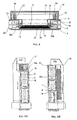
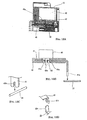
- Fig. 1 is a schematic exploded perspective view showing component parts constituting an electrical junction box 10 intended to be connected to a wire harness, not shown, in a vehicle, such as an automobile.
- Figs. 2 to 4 are sectional views showing the assembled state of the component parts.
- the junction box 10 has a connector module 11, a fuse module 12 and a relay module 13, housed in a casing having a lower case 14, an upper case 15, an intermediate case 16 and opposite side cases 17, 18. Within the casing there is also an electronic control unit 19.
- the cases 14, 15, 16, 17 and 18 are moulded plastics bodies.
- the intermediate case 16 and the electronic control unit 19 are sequentially disposed on the lower case 14, the upper case 15 is mounted on the electronic control unit 19, and the side cases 17, 18 are mounted on the connector module 11.
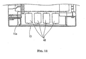
- the relay module 13 is disposed over one side of the connector module 12 in such a way as to expose relays 40 of the relay module 13 to the outside through an opening 15a formed adjacent one side of the upper case 15.
- the fuse module 12 is mounted on the connector module 11 at one side thereof and exposed to the outside through an opening formed between the lower case 14 and the upper case 15.
- a plurality of connector accommodation portions 70, 80 in the form of receiving sockets are formed in a row on each of the side cases 17, 18, which are mounted at opposite sides of the lower case 14 and the upper case 15 in their widthwise direction.
- the number of stages of terminals in each of the connector accommodation portions 70, 80 is three, namely, I, II and III, except at one socket of each where the number of stages of terminals is reduced.
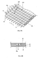
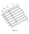
- flexible single-core wires 21 in the form of bare wires of copper are disposed entirely on one surface (lower surface in Fig. 5) of a thin planar insulation substrate 20 made of insulation resin in such a way that the single-core wires 21 extend parallel with one another at a regular pitch in an X-direction.
- Long and narrow bus bars 22 in the form of metal strips of uniform width are disposed on the other surface (upper surface) of the insulation substrate 20 in such a way that the bus bars 22 are parallel with one another at a regular pitch in a Y-direction orthogonal to the X-direction. That is, the single-core wires 21 and the bus bars 22 cross each other, with the insulation substrate 20 interposed therebetween.
- An opening 20a through the substrate 20 is formed at each of selected positions 20b where the single-core wires 21 and the bus bars 22 cross each other.
- the single-core wire 21 is flexed to join it to the bus bar 22.
- the single-core wires 21 and the bus bars 22 are selectively welded to each other by resistance welding to form a desired circuit.
- each bus bar 22 in its longitudinal direction projects from the edges of the insulation substrate 20 in its widthwise direction.
- the projecting portions are bent twice in a zig-zag shape as shown to form horizontal tabs 22b, 22c.
- the tabs 22b and 22c are arranged parallel with one another respectively on the same level.
- the interval between the horizontally arranged tabs 22b is equal to that between adjacent terminal holes 70a of the connector accommodation portion 70 of the side case 17.
- the interval between the horizontally arranged tabs 22c is equal to that between adjacent terminal holes 80a of the connector accommodation portion 80 of the side case 18.
- a circuit plate 100 is constructed of the single-core wires 21 and the bus bars 22 disposed as described above and connected to each other at the required positions, with the insulation substrate 20 sandwiched between them.
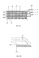
- three such circuit plates 100 identified as 100A, 100B and 100C are layered vertically on each other with interposition of additional insulation plates 25 made of insulation resin.
- the tabs 22b and 22c of the bus bar 22 of the three circuit plates 100 stacked vertically are vertically spaced in correspondence to the interval between adjacent rows of the terminal holes 70a, 80a of the connector accommodation portions 70, 80 of the side case 17, 18. That is, the tabs of the bus bars of the circuit plates 100A, 100B and 100C are level with the terminal holes of the first row, the second row and the third row respectively.
- a bus bar 27, having a circuit configuration formed by punching a conductive metal plate in a conventional manner as shown in Fig. 7b is disposed on a lower surface of the insulation plate 25 below the first circuit plate 100A.
- a bus bar 27 As shown in Fig. 1 also, at one end of the bus bar 27, there are formed a plurality of fuse connection pressure connection terminals 27a arranged parallel with one another and projecting in the extension direction of the single-core wires 21.
- the terminals 27a project from an edge of the module 11 as blades 27b which are brought into contact with terminals of fuses in the fuse module 12.
- the three circuit plates 100A, 100B, 100C to be stacked in three layers are formed by a method shown in Fig. 8.
- a rib or spigot (not shown) projecting from one surface of each of the respective insulation substrates 20 is inserted into an opening formed in each of its bus bars 22 and deformed to fix the bus bars to the insulation substrate 20 parallel to each other.
- the width W (see Fig. 8B) of the insulation substrates 20 is set to the following relationship: 100A>100B>100C.
- the length of the bus bar 22 is larger than the width of the insulation substrate 20.
- the bus bars 22 project from both sides of the insulation substrate 20 in its widthwise direction. The projecting portion of each bus bar 22 is bent vertically and then bent horizontally to form the horizontal tabs 22b, 22c.
- the three insulation substrates 20 are arranged in a row spaced at required intervals, with the middle substrate 20 inverted with respect to the outer two substrates 20, as shown in Fig. 8A.
- each single-core wire 21 is continuously extended parallel with one another across the three insulation substrates 20. Because the surfaces to which the bus bars are fixed are alternately inverted, as described above, each single-core wire 21 is continuously disposed across the upper surface of the substrate 20 in the circuit plate 100A, the lower surface thereof in the circuit plate 100B, and the upper surface thereof in the circuit plate 100C. Gaps are provided between the adjacent substrates 20 in the row, and the wires 21 extend in parallel with one another in the gaps (see Fig. 8B).
- bus bars 22 and the single-core wires 21 are joined with each other by resistance welding through the openings 20a.
- the wires 21 at the gaps between the substrates are then flexed, to bring the substrates 21 into their stacked positions, as shown by arrows in Fig. 8A. Unwanted portions of the continuous wires 21 are cut off before and/or after the circuit plates 100A - 100C are stacked one upon another. Portions of the bus bars may also be removed.
- This manufacturing method is simple, with a small number of operations.
- the fuse connection terminals 27a project parallel with one another from the lowermost end of one edge (left edge in Fig. 1) of the connector module 11.
- the terminals 27a are disposed on a portion 14b formed at one edge (left edge in Fig. 1) of the lower case 14 having partitions to hold the terminals 27a in position.
- the single-core wires 21 of each circuit plate 100 are disposed above the pressure connection terminals 27a.
- the fuse module 12 is disposed at the left edge of the connector module 11. As shown in Fig. 9, the fuse module 12 has a plurality of fuse accommodation portions 31 in the form of sockets arranged widthwise in parallel with one another in a moulded plastics body 30.
- the sockets 31 are in upper and lower stages.
- bus bars 33 are insert moulded in the material of the body 30. At opposite ends of each bus bar 33, there is formed a pair of pressure connection terminals 33a, 33b. A pair of such terminals projects into each fuse accommodation portion 31a at the upper stage of the fuse module 12 as power supply side and load side terminals. A load side terminal formed on another bus bar 33 projects into each fuse accommodation portion 31b at the lower stage of the fuse module 12. One end of each L-shaped bus bar 33 projects into the respective fuse accommodation portion 31a, 31b, whereas the other end thereof extends toward the upper surface of one of the single-core wires 21.
- the pressure connection terminal 33b is connected to the required single-core wire 21 by pressing the wire into the slot of the terminal.
- the pressure connection terminal 33a projected into the fuse accommodation portions 31a, 31b is connected to the terminal of the fuse also by pressure.
- the terminals at the power supply side are the pressure connection terminals 27a of the bus bar 27 described above.
- a fuse 35 is inserted into the fuse accommodation portions 31a, 31b of the fuse module 12 to connect a pair of terminals 35a, 35b of the fuse 35 to a pressure connection terminal 33a of the bus bar 33 or the pressure connection terminal 27a formed on the bus bar 27 at the lowermost layer of the connector module 11 by press fitting.
- bus bars 41 may be directly connected to tabs 33c of the bus bars 33 of the fuse module 12 by pressure connection.
- bus bars 41 are insert moulded in the plastics material of the moulded body 42.
- Relays 40 are received on the outer face of the body 42.
- Terminals 40a of the relay 40 are inserted into openings 42a and 41a in the body 42 and the bus bar 41 respectively and directly mounted on the body 42 with solder 43.
- one portion of the bus bar 41 welded to the terminal 40a of the relay 40 is bent to form a pressure connection terminal 41b at the front end of the bus bar 41.
- the terminal 41b is connected to one of the single-core wires 21 by pressure fitting.
- the electronic control unit 19 has electronic parts 51 mounted on a lower surface of a substrate 50.
- the substrate 50 is placed on supports 53 projecting upwardly at four corners of the intermediate case 16.
- Screws 54 are screwed into screw holes 53a and 50a formed in an upper surface of the support 53 and the substrate 50 respectively to fix the substrate 50 to the intermediate case 16.
- the electronic parts 51 are located in a space between the substrate 50 and the intermediate case 16.
- a plurality of printed electric conductors arranged in parallel with one another at one edge of the substrate 50 are connected to the upper end of a vertically extending assembly of relay terminals 56 through an ECU connector 58 (Fig. 3) or directly.
- Pressure connection terminals are formed at the lower end of the relay terminals 56 to connect with single-core wires 21 of the connector module 11 by pressure fitting.
- the connector module 11, the intermediate case 16 and the electronic control unit 19 are stacked one upon another sequentially on the lower case 14.
- the electric conductors of the electronic control unit 19 are connected to the single-core wires 21 of the connector module 11 through the relay terminals 56 by pressure connection.
- the fuse module 12 is mounted on the connector module 11 at one side thereof to connect the pressure connection terminals 33b disposed at one end of the bus bars 33 of the fuse module 12 to the single-core wires 21 of the connector module 11.
- the relay module 13 is mounted on an upper part of the connector module 11 to connect the pressure connection terminals of the bus bars 41 of the relay module 13 to the single-core wires 21 of the connector module 11.
- the tabs 22b, 22c formed at the ends of each of the bus bars 22 of the connector module 11 project into the terminal holes of the connector accommodation portions 70, 80 of the side cases 17, 18 and in use make connection to connectors (not shown) of a wire harness (not shown).
- the connector is connected to the wire harness on the side surface of the junction box, it is unnecessary to connect the wire harness to the horizontal surface of the lower case 14 or the upper case 15. Thus it is unnecessary to provide space for the wire harness below the lower case or above the upper case. Accordingly, it is possible to reduce the space required in the vehicle for the wire-harness connection.
- the electrical conductors of the connector module 11 are the bus bars and the single-core wires crossing the bus bars.
- the single-core wires and the bus bars are connected to each other by resistance welding at the required crossing positions to form a circuit.
- the connector module 11 can be connected to a connector and a fuse without increasing the number of layers of the bus bars.
- bus bars 22 it is not necessary to punch a conductive metal plate in correspondence to the specific configuration of a circuit. Standard uniform width strip metal may be used. Therefore, it is possible to greatly improve the yield of the conductive metal plate. In addition, it is easy to alter the construction of the circuit by changing the positions where the bus bars 22 and the single-core wires 21 are welded to each other.
- the use of the flexible wires 21 allows thermal stress at the welding locations to be absorbed.
- the electrical conductors of the connector module are connected to those of the fuse module and the relay module by connecting the pressure connection terminals at the ends of the bus bars of the fuse module and the relay module to the single-core wires 21 of the connector module 11 collectively (in a single operation) by pressure fitting, instead of by welding of bus bars. Therefore, it is possible to reduce the number of welding operations and hence improve ease of manufacture.
- a pair of holes 20b and 20c for insertion of pressure connection blades are formed at positions on both sides of each single-core wires 21.
- the pressure connection terminals of bus bars of the relay module 13, described above, are connected to an intermediate portion of the single-core wires 21 of the circuit plate 100A, by inserting the blades of the terminals inserted into the holes 20b and 20c.
- the electric conductors (bus bars) of the relay module can be connected to the intermediate portions of the single-core wires 21 by pressure connection. Thereby it is possible to connect the circuit of the connector module to that of the relay module by pressure connection, instead of welding of bus bars.
- the relay module is connected to the intermediate portions of the single-core wires 21, it is possible to utilize both ends of the single-core wires for pressure connection between the wires and other modules, namely, the bus bars of the fuse module and also for pressure connection between the wires and the electronic control unit.
- simplification can be achieved by connecting the circuit of the relay module, the fuse module and the electronic control unit to the same single-core wire of the conductor module.
- the connector module has the largest number of circuits and requires many variations of its circuit construction, wires and bus bars are used as the electric conductors thereof. They are crossed and welded to each other at selected crossing positions to form the desired circuit thereof. Therefore, it is possible to achieve easy alteration of the circuit construction by merely changing the positions where the bus bars and the single-core wires are connected to each other.
- the tab formed at both ends of the bus bars may project into the terminal hole of the connector accommodation portion, with the tab being flat and not bent.
- Fig. 14 shows a further modification of the junction box of Fig. 1.
- the casing is constructed of an upper case 15' and a lower case 14' in which connector accommodation portions 14a' are formed.
- the tabs 22a of the bus bars 22 of the connector module 11' are bent downward with respect to the insulation substrate 20.
- single-core wires are used in the connector module. Instead, it is possible to use a single-core wire coated with an insulation coating material. In this case, the insulation coating material is removed at the locations where the wire and the bus bar are welded to each other.
- fuse module and the relay module it is possible in the fuse module and the relay module to use circuits like the connector circuit described above having bus bars disposed on one surface of the insulation substrate and the electrical wires disposed on the other surface thereof, to connect to the fuse terminals and relay terminals.
- the long and narrow bus bars and the single-core wires are arranged crossing each other, with the insulation substrate interposed between them and welded to each other at crossing points to form the circuit of the connector module. Therefore, it is possible to insert the tabs at both ends of the bus bars into the terminal holes of the connector accommodation portions formed on the side cases. Further the gap between the bus bars is equal to the gap between the terminal holes. In addition, the gaps between the tabs of the bus bars in the respective layers of the stack of circuit plates is equal to the spacing between the rows of the terminal holes of the connector accommodation portions.
- bus bars do not need to be arranged in a complicated manner.
- the long and narrow strip bus bars are arranged parallel with one another in a simple manner.
- the construction of the present invention can achieve alteration of the circuit construction by merely changing the position of connection between the wires and the bus bars.
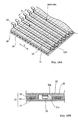
- flexible wires in the form of sectionally rectangular electrical conductors 21 consisting of copper are disposed on one surface (lower surface in Fig. 16) of the thin insulation substrate 20 made of insulation resin in such a way that the electric conductors 21 are parallel with one another at a regular pitch in the X-direction.
- Upper and lower surfaces of the conductors 21 are laminated with insulation films 28, 29 to form a wide flexible flat cable (FFC).
- Elongate bus bars 22 are disposed on the other surface (upper surface) of the insulation substrate 20 in the same manner as shown in Fig. 6 etc. above.
- the electric conductors 21 of the FFC 24 and the bus bars 22 cross each other, with the insulation substrate 20 interposed therebetween.
- an opening 20a is formed at each of selected positions where the conductors 21 and the bus bars 22 cross each other.
- the insulation films 28, 29 of the FFC 24 are separated from the conductor 21 to expose the conductor 21, which is flexed through the opening 20a of the insulation substrate 20.
- a flexed portion 21x of the conductor 21 and the bus bar 22 are welded to each other by resistance welding to form a required circuit connection of the FFC 24 and the bus bars 22.
- a circuit plate 100 (100A - 100C) is constructed of the FFC 24 and the bus bars 22 disposed as described above and connected to each other at the required positions, with the insulation substrate 20 sandwiched therebetween. As shown in Fig. 17, three circuit plates 100 are layered vertically on each other through insulation plates 26 made of insulation resin.
- a bus bar 27, having a circuit configuration formed by punching a conductive metal plate is disposed on a lower surface of the lower circuit plate 100A through an insulation plate 25, as in the above embodiment.
- the three circuit plates 100 (100A - 100C) disposed in three layers are formed by the method shown in Fig. 8, substituting the array of wires 21 of Fig. 8 by the single FFC 24 which is laid across the three substrates.
- Portions of the conductors 21 which are not wanted in the circuit of the continuous FFC 24 are cut off before and/or after the circuit plates 100A - 100C are layered one upon another.
- the FFC 24 is disposed on the lower surface of the insulation substrate 20, and the bus bars 22 are disposed on the upper surface thereof, with the insulation substrate 20 interposed between the FFC 24 and the bus bars 22.
- the FFC 24 and the bus bars 22 confront each other, with the insulation plates 26 interposed therebetween.
- Fig. 18 shows how, in a similar manner to that of Fig. 10B, the bus bars 22 of the fuse module make pressure connection to the conductors 21 of the FFC 24. It is not necessary to remove the insulation 22, 23 before pressing the bus bar 33 and the FFC 24 together.
- Fig. 19 likewise shows pressure connection of the bus bars 41 of the relay module to the conductors 21 of the FFC 24.
- the connections of the FFC 24 to the electronic control unit via the relay terminals 56 is also carried out by pressure connections.
- FFC 24 may be used in other versions of the connector module 11.
- flexible single-core wires 60 similar to the wires 21 of Fig. 6 may be disposed on one surface of the insulation substrate 20 and the FFC 24 may be disposed on the other surface thereof.
- FFCs may be disposed on both surfaces of the insulation substrate 20 as shown in Fig. 20B. In both cases, the electrical conductors on the two surfaces of the insulation substrate 20 are orthogonal to each other and cross each other. They are connected at selected crossing points by bending and welding.
- the FFC may be extended from the connector module to be used as a wire harness, namely to connect it to other component parts of the vehicle body. That is, the FFC may be extended outside the junction box to be an external harness.
- the connector module has the largest number of circuits and requires alteration of its circuit configuration
- electric wires, elongate bus bars, and the FFC are used as the electric conductors thereof. They cross and are welded to each other at crossing positions to form the circuit.
- the bus bars do not necessarily have to be used.
- the FFC can be disposed continuously very easily on one surface of the insulation substrates with the insulation substrates arranged in a row, thus simplifying the manufacture.
Landscapes
- Engineering & Computer Science (AREA)
- Microelectronics & Electronic Packaging (AREA)
- Mechanical Engineering (AREA)
- Connection Or Junction Boxes (AREA)
- Multi-Conductor Connections (AREA)
Applications Claiming Priority (9)
| Application Number | Priority Date | Filing Date | Title |
|---|---|---|---|
| JP2000326959 | 2000-10-26 | ||
| JP2000326959A JP3685036B2 (ja) | 2000-10-26 | 2000-10-26 | ジャンクションボックス |
| JP2000330931 | 2000-10-30 | ||
| JP2000330931A JP3685038B2 (ja) | 2000-10-30 | 2000-10-30 | ジャンクションボックス |
| JP2000334784A JP3685040B2 (ja) | 2000-11-01 | 2000-11-01 | ジャンクションボックスおよび該ジャンクションボックスの形成方法 |
| JP2000334784 | 2000-11-01 | ||
| JP2000338048 | 2000-11-06 | ||
| JP2000338048 | 2000-11-06 | ||
| EP01308982A EP1201505B1 (de) | 2000-10-26 | 2001-10-23 | Elektrische Kraftfahrzeugverbindungsdose |
Related Parent Applications (1)
| Application Number | Title | Priority Date | Filing Date |
|---|---|---|---|
| EP01308982A Division EP1201505B1 (de) | 2000-10-26 | 2001-10-23 | Elektrische Kraftfahrzeugverbindungsdose |
Publications (1)
| Publication Number | Publication Date |
|---|---|
| EP1586488A1 true EP1586488A1 (de) | 2005-10-19 |
Family
ID=27481739
Family Applications (2)
| Application Number | Title | Priority Date | Filing Date |
|---|---|---|---|
| EP05013808A Withdrawn EP1586488A1 (de) | 2000-10-26 | 2001-10-23 | Elektrische Kraftfahrzeugverbindungsdose |
| EP01308982A Expired - Lifetime EP1201505B1 (de) | 2000-10-26 | 2001-10-23 | Elektrische Kraftfahrzeugverbindungsdose |
Family Applications After (1)
| Application Number | Title | Priority Date | Filing Date |
|---|---|---|---|
| EP01308982A Expired - Lifetime EP1201505B1 (de) | 2000-10-26 | 2001-10-23 | Elektrische Kraftfahrzeugverbindungsdose |
Country Status (3)
| Country | Link |
|---|---|
| US (3) | US6670548B2 (de) |
| EP (2) | EP1586488A1 (de) |
| DE (1) | DE60125008T2 (de) |
Cited By (1)
| Publication number | Priority date | Publication date | Assignee | Title |
|---|---|---|---|---|
| CN103057489A (zh) * | 2013-01-05 | 2013-04-24 | 杭州普拉格新能源汽车有限公司 | 一种电驱动汽车动力控制盒 |
Families Citing this family (32)
| Publication number | Priority date | Publication date | Assignee | Title |
|---|---|---|---|---|
| JP2004064912A (ja) * | 2002-07-30 | 2004-02-26 | Hitachi Ltd | 自動車制御装置 |
| CA2408483C (en) * | 2002-10-17 | 2011-01-04 | Yujie Han | Laser chemical fabrication of nanostructures |
| JP4114497B2 (ja) * | 2003-02-14 | 2008-07-09 | 住友電装株式会社 | 回路構成体用ケース及び回路構成体の製造方法 |
| JP2004328939A (ja) * | 2003-04-25 | 2004-11-18 | Sumitomo Wiring Syst Ltd | 電気接続箱 |
| JP4263550B2 (ja) * | 2003-07-31 | 2009-05-13 | 矢崎総業株式会社 | ジャンクションブロック |
| US7470130B2 (en) | 2003-07-31 | 2008-12-30 | Yazaki Corporation | Junction box having components combined to an inner cover |
| JP4161877B2 (ja) * | 2003-11-05 | 2008-10-08 | 住友電装株式会社 | 回路構成体、その製造方法及び配電ユニット |
| KR200358267Y1 (ko) * | 2004-03-20 | 2004-08-06 | 영화테크(주) | 차량용 통합 전자 모듈의 구조 |
| JP4424042B2 (ja) * | 2004-04-06 | 2010-03-03 | 住友電装株式会社 | 車載用リレーおよび電気接続箱 |
| JP4254601B2 (ja) * | 2004-04-02 | 2009-04-15 | 住友電装株式会社 | 電気接続箱 |
| JP4254600B2 (ja) * | 2004-04-01 | 2009-04-15 | 住友電装株式会社 | 電気接続箱 |
| US20050260886A1 (en) * | 2004-05-20 | 2005-11-24 | Leonard Persits | Fuse block cover |
| US20060023441A1 (en) * | 2004-08-02 | 2006-02-02 | Robert Bosch Gmbh | Modularized circuit component |
| JP4322752B2 (ja) * | 2004-08-03 | 2009-09-02 | 株式会社オートネットワーク技術研究所 | 電気接続箱 |
| US8570699B2 (en) * | 2005-04-22 | 2013-10-29 | Lear Corporation | Relayless and fuseless junction box |
| US6992248B1 (en) * | 2005-04-25 | 2006-01-31 | Sumitomo Electric Wiring Systems - Detroit Technical Center, Inc. | Junction box assembly with connectivity assurance |
| DE102005026205B3 (de) * | 2005-06-07 | 2006-10-05 | Siemens Ag | Gerät und Verfahren zum Herstellen eines Geräts |
| JP4868928B2 (ja) * | 2006-04-26 | 2012-02-01 | 矢崎総業株式会社 | ジャンクションブロック |
| US20080224814A1 (en) * | 2007-03-13 | 2008-09-18 | Lear Corporation | Electrical assembly and manufacturing method |
| JP5108402B2 (ja) * | 2007-07-09 | 2012-12-26 | 株式会社オートネットワーク技術研究所 | 電気接続箱 |
| JP5316051B2 (ja) * | 2009-02-12 | 2013-10-16 | 住友電装株式会社 | 電気接続箱 |
| US8897023B2 (en) * | 2009-05-15 | 2014-11-25 | Hamilton Sundstrand Corporation | Motor controller assembly with capacitor thermal isolation |
| KR101181176B1 (ko) * | 2010-10-11 | 2012-09-18 | 현대자동차주식회사 | 저전압 및 고전압 통합 전압 분배 장치 |
| SG2013094396A (en) * | 2013-12-19 | 2015-07-30 | Rockwell Automation Asia Pacific Business Ctr Pte Ltd | Slice-io housing with side ventilation |
| US9864352B2 (en) | 2015-06-01 | 2018-01-09 | Rockwell Automation Asia Pacific Business Ctr. Pte., Ltd. | Slice I/O—field power bus breaker |
| DE102015115624B4 (de) * | 2015-09-16 | 2021-11-11 | Lisa Dräxlmaier GmbH | Stromverteiler mit aufsteckbarer elektronik |
| EP3557602B1 (de) * | 2016-12-15 | 2024-04-24 | Amogreentech Co., Ltd. | Leistungsrelaisanordnung |
| US10349539B2 (en) | 2017-10-03 | 2019-07-09 | Aptiv Technologies Limited | Vehicle electrical center and method of manufacturing same |
| US11342692B2 (en) | 2020-05-13 | 2022-05-24 | Tomas M. Aguilar | Modular junction boxes |
| JP7073443B2 (ja) * | 2020-05-26 | 2022-05-23 | 株式会社ホンダロック | ケース内回路基板への端子接続構造 |
| EP4052968A1 (de) | 2021-03-01 | 2022-09-07 | Aptiv Technologies Limited | Hochspannungsleistungsverteiler |
| EP4052969A1 (de) * | 2021-03-05 | 2022-09-07 | Aptiv Technologies Limited | Elektrischer spleissverbinder |
Citations (7)
| Publication number | Priority date | Publication date | Assignee | Title |
|---|---|---|---|---|
| JPH05161234A (ja) * | 1991-12-02 | 1993-06-25 | Yazaki Corp | 電気接続箱 |
| EP0572052A1 (de) * | 1992-05-27 | 1993-12-01 | General Motors Corporation | Zentrale Stromverteilungsanordnung |
| EP0818356A2 (de) * | 1996-07-09 | 1998-01-14 | Sumitomo Wiring Systems, Ltd. | Elektrischer Steckverbinder zur Verwendung in einem Kraftfahrzeug |
| EP0985585A2 (de) * | 1998-09-09 | 2000-03-15 | Sumitomo Wiring Systems, Ltd. | Elektrische Verbindungsdose |
| JP2000112691A (ja) | 1998-10-07 | 2000-04-21 | Seiko Epson Corp | ネットワーク印刷システム、ネットワークプリンタ及びネットワーク印刷方法 |
| US6094811A (en) * | 1997-03-27 | 2000-08-01 | Neumann-Henneberg; Wolf | Central electric system for a motor vehicle and method of manufacturing same |
| EP1145914A2 (de) | 2000-04-13 | 2001-10-17 | Sumitomo Wiring Systems, Ltd. | Elektrisches Verbindungsgehäuse |
Family Cites Families (30)
| Publication number | Priority date | Publication date | Assignee | Title |
|---|---|---|---|---|
| US506060A (en) * | 1893-10-03 | Feed mechanism for rolling-mills | ||
| US3142112A (en) * | 1960-03-30 | 1964-07-28 | Hughes Aircraft Co | Method of making an electrical interconnection grid |
| US4015328A (en) * | 1975-06-02 | 1977-04-05 | Mcdonough Cletus G | Multilayered circuit assembly including an eyelet for making weldable connections and a method of making said assembly |
| US4630362A (en) * | 1981-10-26 | 1986-12-23 | Burndy Corporation | Apparatus for installing electrical on flat conductor cable |
| US4821409A (en) * | 1981-10-26 | 1989-04-18 | Burndy Corporation | Electrical connection apparatus for flat conductor cables and similar articles |
| JPH02219413A (ja) * | 1989-02-16 | 1990-09-03 | Yazaki Corp | 電気接続箱 |
| US4899439A (en) * | 1989-06-15 | 1990-02-13 | Microelectronics And Computer Technology Corporation | Method of fabricating a high density electrical interconnect |
| JP2752010B2 (ja) * | 1991-06-25 | 1998-05-18 | 矢崎総業株式会社 | 電気接続箱 |
| JPH0539124A (ja) | 1991-08-01 | 1993-02-19 | Matsushita Electric Ind Co Ltd | 回路基板収納装置 |
| US5229922A (en) * | 1991-09-26 | 1993-07-20 | Yazaki Corporation | Electrical junction box with stacked insulating plates and bus-bars with stepped tabs |
| US5346117A (en) * | 1993-07-27 | 1994-09-13 | International Business Machines Corporation | Method of fabricating a parallel processor package |
| US5384690A (en) * | 1993-07-27 | 1995-01-24 | International Business Machines Corporation | Flex laminate package for a parallel processor |
| US5432998A (en) * | 1993-07-27 | 1995-07-18 | International Business Machines, Corporation | Method of solder bonding processor package |
| US5764487A (en) * | 1996-08-06 | 1998-06-09 | Yazaki Corporation | Junction block with integral printed circuit board and electrical connector for same |
| JPH10210631A (ja) * | 1997-01-24 | 1998-08-07 | Sumitomo Wiring Syst Ltd | 分岐接続箱、分岐接続箱の組み付け方法 |
| US5995380A (en) * | 1998-05-12 | 1999-11-30 | Lear Automotive Dearborn, Inc. | Electric junction box for an automotive vehicle |
| JP3435690B2 (ja) | 1998-08-24 | 2003-08-11 | 矢崎総業株式会社 | 配線板の接続構造及び配線板組立体の製造方法 |
| JP3785276B2 (ja) * | 1998-09-10 | 2006-06-14 | 矢崎総業株式会社 | 電気接続箱 |
| DE69929384T2 (de) * | 1998-10-09 | 2006-08-31 | Sumitomo Wiring Systems, Ltd., Yokkaichi | Gitterleiterplatte |
| JP3680603B2 (ja) * | 1998-12-24 | 2005-08-10 | 住友電装株式会社 | 積層基板 |
| DE69908896T2 (de) * | 1999-01-04 | 2004-05-19 | Sumitomo Wiring Systems, Ltd., Yokkaichi | Elektrische Anschlussdose mit einer Sammelschiene |
| JP3338004B2 (ja) * | 1999-06-25 | 2002-10-28 | 株式会社オートネットワーク技術研究所 | バスバーの接続構造 |
| JP3446672B2 (ja) * | 1999-07-30 | 2003-09-16 | 住友電装株式会社 | 電気接続箱 |
| JP3543713B2 (ja) * | 2000-01-20 | 2004-07-21 | 住友電装株式会社 | 電気接続箱 |
| JP4097388B2 (ja) * | 2000-07-21 | 2008-06-11 | 住友電装株式会社 | ジャンクションボックスの組立方法および該方法で組み立てられたジャンクションボックス |
| JP4097392B2 (ja) * | 2000-08-09 | 2008-06-11 | 住友電装株式会社 | ジャンクションボックスおよびジャンクションボックスの組立方法 |
| US6514091B2 (en) * | 2000-11-28 | 2003-02-04 | Sumitomo Wiring Systems, Ltd. | Electrical junction box for a vehicle |
| US6511331B2 (en) * | 2000-11-28 | 2003-01-28 | Sumitomo Wiring Systems, Ltd. | Electrical junction box for a vehicle |
| JP2002186136A (ja) * | 2000-12-14 | 2002-06-28 | Yazaki Corp | 電気接続箱 |
| JP3977609B2 (ja) * | 2001-04-27 | 2007-09-19 | 矢崎総業株式会社 | 電気接続箱 |
-
2001
- 2001-10-23 EP EP05013808A patent/EP1586488A1/de not_active Withdrawn
- 2001-10-23 DE DE60125008T patent/DE60125008T2/de not_active Expired - Lifetime
- 2001-10-23 EP EP01308982A patent/EP1201505B1/de not_active Expired - Lifetime
- 2001-10-26 US US09/984,064 patent/US6670548B2/en not_active Expired - Fee Related
-
2003
- 2003-04-18 US US10/418,168 patent/US6677521B2/en not_active Expired - Fee Related
- 2003-04-18 US US10/418,148 patent/US6851185B2/en not_active Expired - Fee Related
Patent Citations (7)
| Publication number | Priority date | Publication date | Assignee | Title |
|---|---|---|---|---|
| JPH05161234A (ja) * | 1991-12-02 | 1993-06-25 | Yazaki Corp | 電気接続箱 |
| EP0572052A1 (de) * | 1992-05-27 | 1993-12-01 | General Motors Corporation | Zentrale Stromverteilungsanordnung |
| EP0818356A2 (de) * | 1996-07-09 | 1998-01-14 | Sumitomo Wiring Systems, Ltd. | Elektrischer Steckverbinder zur Verwendung in einem Kraftfahrzeug |
| US6094811A (en) * | 1997-03-27 | 2000-08-01 | Neumann-Henneberg; Wolf | Central electric system for a motor vehicle and method of manufacturing same |
| EP0985585A2 (de) * | 1998-09-09 | 2000-03-15 | Sumitomo Wiring Systems, Ltd. | Elektrische Verbindungsdose |
| JP2000112691A (ja) | 1998-10-07 | 2000-04-21 | Seiko Epson Corp | ネットワーク印刷システム、ネットワークプリンタ及びネットワーク印刷方法 |
| EP1145914A2 (de) | 2000-04-13 | 2001-10-17 | Sumitomo Wiring Systems, Ltd. | Elektrisches Verbindungsgehäuse |
Non-Patent Citations (1)
| Title |
|---|
| PATENT ABSTRACTS OF JAPAN vol. 017, no. 566 (E - 1446) 13 October 1993 (1993-10-13) * |
Cited By (1)
| Publication number | Priority date | Publication date | Assignee | Title |
|---|---|---|---|---|
| CN103057489A (zh) * | 2013-01-05 | 2013-04-24 | 杭州普拉格新能源汽车有限公司 | 一种电驱动汽车动力控制盒 |
Also Published As
| Publication number | Publication date |
|---|---|
| US6851185B2 (en) | 2005-02-08 |
| US20020050375A1 (en) | 2002-05-02 |
| US6670548B2 (en) | 2003-12-30 |
| EP1201505A2 (de) | 2002-05-02 |
| DE60125008D1 (de) | 2007-01-18 |
| US20030205397A1 (en) | 2003-11-06 |
| DE60125008T2 (de) | 2007-07-05 |
| US20030205398A1 (en) | 2003-11-06 |
| EP1201505A3 (de) | 2003-11-19 |
| US6677521B2 (en) | 2004-01-13 |
| EP1201505B1 (de) | 2006-12-06 |
Similar Documents
| Publication | Publication Date | Title |
|---|---|---|
| EP1201505B1 (de) | Elektrische Kraftfahrzeugverbindungsdose | |
| US6514091B2 (en) | Electrical junction box for a vehicle | |
| EP2425689B1 (de) | Verbindungseinrichtung | |
| CN114583401A (zh) | 电池连接模块 | |
| CN2572578Y (zh) | 卡缘连接器 | |
| US20030148648A1 (en) | Board connector | |
| JP3685038B2 (ja) | ジャンクションボックス | |
| JP3685046B2 (ja) | ジャンクションボックス | |
| JPH06208873A (ja) | フレキシブルプリント配線板を用いたワイヤリングハーネス | |
| JP3736342B2 (ja) | ジャンクションボックスおよびコネクタモジュールの形成方法 | |
| JP3685041B2 (ja) | ジャンクションボックス | |
| JP3685036B2 (ja) | ジャンクションボックス | |
| JP3685045B2 (ja) | ジャンクションボックス | |
| JP3685040B2 (ja) | ジャンクションボックスおよび該ジャンクションボックスの形成方法 | |
| JP2571466Y2 (ja) | 電気接続箱 | |
| JP3352945B2 (ja) | 電気接続箱の配線材と電子ユニットのプリント基板部との接続構造 | |
| JP2000022353A (ja) | 電気接続箱の配線材と電子ユニットのプリント基板部との接続部構造 | |
| TWM610685U (zh) | 連接器總成 | |
| JP3578039B2 (ja) | ジャンクションボックスの内部回路接続構造 | |
| JP2622205B2 (ja) | フラットワイヤハーネスの製造方法 | |
| JP3339831B2 (ja) | 配線板および該配線板を備えた電気接続箱 | |
| JP2002204519A (ja) | ジャンクションボックス | |
| JP3757792B2 (ja) | ジャンクションボックス | |
| JP2002186139A (ja) | ジャンクションボックス内に収容する回路板の形成方法および回路板を収容しているジャンクションボックス | |
| JPH05266935A (ja) | ケーブル接続用コネクタ |
Legal Events
| Date | Code | Title | Description |
|---|---|---|---|
| PUAI | Public reference made under article 153(3) epc to a published international application that has entered the european phase |
Free format text: ORIGINAL CODE: 0009012 |
|
| AC | Divisional application: reference to earlier application |
Ref document number: 1201505 Country of ref document: EP Kind code of ref document: P |
|
| AK | Designated contracting states |
Kind code of ref document: A1 Designated state(s): AT BE CH CY DE DK ES FI FR GB GR IE IT LI LU MC NL PT SE TR |
|
| AX | Request for extension of the european patent |
Extension state: AL LT LV MK RO SI |
|
| AKX | Designation fees paid |
Designated state(s): DE FR |
|
| STAA | Information on the status of an ep patent application or granted ep patent |
Free format text: STATUS: THE APPLICATION IS DEEMED TO BE WITHDRAWN |
|
| 18D | Application deemed to be withdrawn |
Effective date: 20060420 |