EP0985585A2 - Elektrische Verbindungsdose - Google Patents
Elektrische Verbindungsdose Download PDFInfo
- Publication number
- EP0985585A2 EP0985585A2 EP99117811A EP99117811A EP0985585A2 EP 0985585 A2 EP0985585 A2 EP 0985585A2 EP 99117811 A EP99117811 A EP 99117811A EP 99117811 A EP99117811 A EP 99117811A EP 0985585 A2 EP0985585 A2 EP 0985585A2
- Authority
- EP
- European Patent Office
- Prior art keywords
- wires
- busbar
- connection box
- insulative plate
- wire
- Prior art date
- Legal status (The legal status is an assumption and is not a legal conclusion. Google has not performed a legal analysis and makes no representation as to the accuracy of the status listed.)
- Granted
Links
- 238000009413 insulation Methods 0.000 abstract description 7
- 239000010410 layer Substances 0.000 description 4
- 238000004519 manufacturing process Methods 0.000 description 4
- 238000000034 method Methods 0.000 description 4
- 238000012986 modification Methods 0.000 description 2
- 230000004048 modification Effects 0.000 description 2
- 230000015572 biosynthetic process Effects 0.000 description 1
- 239000012467 final product Substances 0.000 description 1
- 239000012212 insulator Substances 0.000 description 1
- 230000000284 resting effect Effects 0.000 description 1
- 230000000717 retained effect Effects 0.000 description 1
- 239000002356 single layer Substances 0.000 description 1
Images


Classifications
-
- B—PERFORMING OPERATIONS; TRANSPORTING
- B60—VEHICLES IN GENERAL
- B60R—VEHICLES, VEHICLE FITTINGS, OR VEHICLE PARTS, NOT OTHERWISE PROVIDED FOR
- B60R16/00—Electric or fluid circuits specially adapted for vehicles and not otherwise provided for; Arrangement of elements of electric or fluid circuits specially adapted for vehicles and not otherwise provided for
- B60R16/02—Electric or fluid circuits specially adapted for vehicles and not otherwise provided for; Arrangement of elements of electric or fluid circuits specially adapted for vehicles and not otherwise provided for electric constitutive elements
- B60R16/023—Electric or fluid circuits specially adapted for vehicles and not otherwise provided for; Arrangement of elements of electric or fluid circuits specially adapted for vehicles and not otherwise provided for electric constitutive elements for transmission of signals between vehicle parts or subsystems
- B60R16/0238—Electrical distribution centers
-
- H—ELECTRICITY
- H05—ELECTRIC TECHNIQUES NOT OTHERWISE PROVIDED FOR
- H05K—PRINTED CIRCUITS; CASINGS OR CONSTRUCTIONAL DETAILS OF ELECTRIC APPARATUS; MANUFACTURE OF ASSEMBLAGES OF ELECTRICAL COMPONENTS
- H05K3/00—Apparatus or processes for manufacturing printed circuits
- H05K3/30—Assembling printed circuits with electric components, e.g. with resistor
- H05K3/32—Assembling printed circuits with electric components, e.g. with resistor electrically connecting electric components or wires to printed circuits
- H05K3/325—Assembling printed circuits with electric components, e.g. with resistor electrically connecting electric components or wires to printed circuits by abutting or pinching, i.e. without alloying process; mechanical auxiliary parts therefor
- H05K3/326—Assembling printed circuits with electric components, e.g. with resistor electrically connecting electric components or wires to printed circuits by abutting or pinching, i.e. without alloying process; mechanical auxiliary parts therefor the printed circuit having integral resilient or deformable parts, e.g. tabs or parts of flexible circuits
-
- Y—GENERAL TAGGING OF NEW TECHNOLOGICAL DEVELOPMENTS; GENERAL TAGGING OF CROSS-SECTIONAL TECHNOLOGIES SPANNING OVER SEVERAL SECTIONS OF THE IPC; TECHNICAL SUBJECTS COVERED BY FORMER USPC CROSS-REFERENCE ART COLLECTIONS [XRACs] AND DIGESTS
- Y10—TECHNICAL SUBJECTS COVERED BY FORMER USPC
- Y10S—TECHNICAL SUBJECTS COVERED BY FORMER USPC CROSS-REFERENCE ART COLLECTIONS [XRACs] AND DIGESTS
- Y10S439/00—Electrical connectors
- Y10S439/949—Junction box with busbar for plug-socket type interconnection with receptacle
Definitions
- the present Invention is directed to an electrical connection box, particularly designed for use in automobiles. More specifically, it provides a high-density branching circuit wherein the wire connection section is on a busbar stacked on an insulative plate and the wire serves as an intermediate connection, thereby increasing the wire efficiency of the busbar. Preferably, the elements are within the electrical connection box.
- the Invention will be described with relation to an automobile, but its use is not limited thereto.
- busbars 7 and 8 are to be connected to each other. However, busbar 9 is located between them. In order to avoid electrical contact between busbars 7 and 8 and busbar 9, wire 6 is pressed between blades 11, thereby avoiding busbar 9 and securing the electrical connection between busbars 7 and 8.
- insulative plate 4D carries busbars 7 and 8. Connection sections 10 pass through openings 17 in insulative plate 4E and blades 11 cut through the insulation on wires 6 to make electrical contact with the cores thereof.
- FIG 5 A further modification is shown in Figure 5, wherein insulative plate 4C carries busbar 9 and insulative plate 4D carries busbars 7 and 8. Connection section 10 of busbar 9 passes through opening 17 in insulative plate 4D and through opening 17 in insulative plate 4E. Since busbars 7 and 8 are resting on insulative plate 4D, connection sections 10 thereof only have to pass through openings 17 in insulation plate 4E. However, since busbar 9 rests on insulative plate 4C, section 10 passes through openings 17 in plates 4D and 4E.
- the busbar method is such that an increased number of circuits in the connection box is accompanied by a decrease in the number of circuits which can be placed on a single layer.
- a greater number of layers must be provided, thereby making the connection box larger and more complex.
- busbar layers are stacked with layers formed from wires and pressure-connection terminals. These layers are connected to external circuits.
- this combined method results in higher production costs, creating problems in manufacture of low cost automobiles.
- an electrical connection box containing at least one generally planar base insulative plate.
- the busbar has one or more pressure connection sections, each of which includes a pair of blades which cut through the insulation on the wires to make electrical contact with the core thereof.
- the busbars are bent so that they are in alignment with the predetermined points and the plurality of openings giving access thereto.
- the bent portions of the busbars form connection sections which, when the box is assembled, extend through the openings and terminate in contact blades.
- the blades are adapted to receive the insulated wires; when the wires are pressed therein, the blades cut through the insulation and make electrical contact with the wire core.
- the insulated wires are straight, parallel to each other, and located in a wire concentration section on or adjacent the second surface of the base insulative plates.
- the wire concentration section is in register with the pressure connection section.
- the various blades can engage the wires and make electrical contact therewith by means of a single application of pressure.
- all of the wires are connected at one time and it is not necessary to insert each wire individually.
- all of the wires should be of the same length so that they can be easily placed in the wire concentration section.
- pairs of wire guides are provided. These constitute protuberances extending from the second surface of the insulative plates and are spaced apart transversely to the axes of the wires by a distance which does not exceed the diameter of an individual wire. Preferably, the distance should be slightly less than the wire diameter.
- Some of the connection sections may extend, not only through an opening in the base insulative plate, but also through further opening(s) in one or more additional insulative plates, thereby making contact with the plurality of wires on one of the additional insulative plates.
- a preferred form of the Invention consists of a plurality of interleaved insulative plates. These stacked plates carry either the busbar(s), the wires, or both. --
- the busbars may be spaced from the wires to which they are to be connected by one or more insulative plates. In such cases, the openings are aligned with one another and with the point at which the connections between the wires and the busbars are desired.
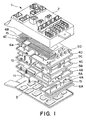
- connection box 1 comprises upper case 2 and lower case 3.
- insulator plates 4A, 4B, 4C, 4D, and 4E and busbars 5A, 5B, 5C, and 5D.
- Wires 6A and 6B are located in wire concentration sections 15.
- Wires 6a, 6b, 6c, 6d, 6e, 6f, and 6g are retained on the second surface of (for example) insulative plate 4E by wire guides 16. Openings 17, through which connection sections 10 project to make contact with the wires, extend through insulative plate 4E.
- connection sections 10 terminate in blades 11 which are adapted to receive wires 6 and cut through the insulation thereon to make contact with the electrically conductive wire cores. Referring more specifically to Figure 6, blades 11 on connection sections 10 are in electrical contact with wires 6. Unused sections 12 (cross hatched) are cut away in order to minimize the bulk of the finished connector box.
- a second plurality of wires 6B is located adjacent wire concentration section 15.
- these wires are parallel to each other throughout most of their length, but are provided with cross over point 6a where the wires come together.
- circuits can be modified simply by adding or removing connections with the wires.
- wires used for intermediate connections for the busbars can be concentrated in the wire concentration section and preferably arranged in straight lines parallel to each other. This makes the wiring easier and the equipment necessary is readily available.
- the device of the present Invention is well suited for mass production and low assembly costs.
Landscapes
- Engineering & Computer Science (AREA)
- Mechanical Engineering (AREA)
- Metallurgy (AREA)
- Manufacturing & Machinery (AREA)
- Microelectronics & Electronic Packaging (AREA)
- Connection Or Junction Boxes (AREA)
- Connections By Means Of Piercing Elements, Nuts, Or Screws (AREA)
- Multi-Conductor Connections (AREA)
- Coupling Device And Connection With Printed Circuit (AREA)
Applications Claiming Priority (2)
| Application Number | Priority Date | Filing Date | Title |
|---|---|---|---|
| JP25572198 | 1998-09-09 | ||
| JP25572198A JP3336971B2 (ja) | 1998-09-09 | 1998-09-09 | 自動車用電気接続箱 |
Publications (3)
| Publication Number | Publication Date |
|---|---|
| EP0985585A2 true EP0985585A2 (de) | 2000-03-15 |
| EP0985585A3 EP0985585A3 (de) | 2000-07-26 |
| EP0985585B1 EP0985585B1 (de) | 2004-05-12 |
Family
ID=17282733
Family Applications (1)
| Application Number | Title | Priority Date | Filing Date |
|---|---|---|---|
| EP99117811A Expired - Lifetime EP0985585B1 (de) | 1998-09-09 | 1999-09-09 | Elektrische Verbindungsdose |
Country Status (5)
| Country | Link |
|---|---|
| US (1) | US6220875B1 (de) |
| EP (1) | EP0985585B1 (de) |
| JP (1) | JP3336971B2 (de) |
| CN (1) | CN1192464C (de) |
| DE (1) | DE69917162T2 (de) |
Cited By (4)
| Publication number | Priority date | Publication date | Assignee | Title |
|---|---|---|---|---|
| EP1174973A1 (de) * | 2000-07-21 | 2002-01-23 | Sumitomo Wiring Systems, Ltd. | Verbindungsgehäuse |
| EP1145914A3 (de) * | 2000-04-13 | 2002-07-17 | Sumitomo Wiring Systems, Ltd. | Elektrisches Verbindungsgehäuse |
| EP1201505A3 (de) * | 2000-10-26 | 2003-11-19 | Sumitomo Wiring Systems, Ltd. | Elektrische Kraftfahrzeugverbindungsdose |
| EP1179453A3 (de) * | 2000-08-09 | 2004-07-28 | Sumitomo Wiring Systems, Ltd. | Anschlusskasten |
Families Citing this family (14)
| Publication number | Priority date | Publication date | Assignee | Title |
|---|---|---|---|---|
| JP3676636B2 (ja) * | 1999-12-27 | 2005-07-27 | 矢崎総業株式会社 | 層間接続構造 |
| JP2002058130A (ja) * | 2000-08-07 | 2002-02-22 | Sumitomo Wiring Syst Ltd | 電気接続箱 |
| JP2002186150A (ja) * | 2000-12-12 | 2002-06-28 | Sumitomo Wiring Syst Ltd | 高電圧用電気接続箱 |
| DE10141400A1 (de) * | 2001-08-23 | 2003-03-13 | Bosch Gmbh Robert | Steuergerät |
| JP4254600B2 (ja) | 2004-04-01 | 2009-04-15 | 住友電装株式会社 | 電気接続箱 |
| JP4424042B2 (ja) | 2004-04-06 | 2010-03-03 | 住友電装株式会社 | 車載用リレーおよび電気接続箱 |
| JP4254601B2 (ja) | 2004-04-02 | 2009-04-15 | 住友電装株式会社 | 電気接続箱 |
| US20060199137A1 (en) * | 2005-03-04 | 2006-09-07 | Norbert Abels | Orthodontic retainer system with removable retaining wire |
| CA2605268C (en) * | 2005-04-21 | 2014-01-28 | Autonetworks Technologies, Ltd. | Electric connection box |
| JP4447607B2 (ja) * | 2005-10-14 | 2010-04-07 | 株式会社オートネットワーク技術研究所 | 電気接続箱 |
| JP2009017705A (ja) * | 2007-07-05 | 2009-01-22 | Yazaki Corp | 電気接続箱及び電気接続箱の製造方法 |
| JP2013028252A (ja) * | 2011-07-28 | 2013-02-07 | Yazaki Corp | バスバ切断機構、バスバ切断方法、車両用室内照明灯 |
| JP5800624B2 (ja) * | 2011-07-28 | 2015-10-28 | 矢崎総業株式会社 | 電気接続箱のバスバー端部構造 |
| CN104332830A (zh) * | 2014-10-30 | 2015-02-04 | 北奔重型汽车集团有限公司 | 一种可扩展的配电模块 |
Family Cites Families (9)
| Publication number | Priority date | Publication date | Assignee | Title |
|---|---|---|---|---|
| JP2740773B2 (ja) | 1988-04-14 | 1998-04-15 | 矢崎総業株式会社 | 電気接続箱およびその製造方法 |
| JPH02219413A (ja) * | 1989-02-16 | 1990-09-03 | Yazaki Corp | 電気接続箱 |
| JP2752010B2 (ja) | 1991-06-25 | 1998-05-18 | 矢崎総業株式会社 | 電気接続箱 |
| JP2921622B2 (ja) | 1992-07-28 | 1999-07-19 | 矢崎総業株式会社 | 配線板組立体の配線方法および配線装置 |
| JP2929414B2 (ja) | 1994-07-05 | 1999-08-03 | 矢崎総業株式会社 | 電気接続箱 |
| GB2318226B (en) | 1994-07-05 | 1998-07-15 | Yazaki Corp | Electrical junction box |
| JPH08179885A (ja) * | 1994-12-22 | 1996-07-12 | Sharp Corp | 表示装置 |
| JP3075118B2 (ja) | 1994-12-29 | 2000-08-07 | 住友電装株式会社 | 電気接続箱 |
| US5715135A (en) | 1996-08-12 | 1998-02-03 | General Motors Corporation | Electrical distribution center with two-piece insulation assembly |
-
1998
- 1998-09-09 JP JP25572198A patent/JP3336971B2/ja not_active Expired - Fee Related
-
1999
- 1999-09-07 CN CNB991185463A patent/CN1192464C/zh not_active Expired - Fee Related
- 1999-09-08 US US09/391,536 patent/US6220875B1/en not_active Expired - Lifetime
- 1999-09-09 DE DE69917162T patent/DE69917162T2/de not_active Expired - Lifetime
- 1999-09-09 EP EP99117811A patent/EP0985585B1/de not_active Expired - Lifetime
Non-Patent Citations (1)
| Title |
|---|
| None |
Cited By (8)
| Publication number | Priority date | Publication date | Assignee | Title |
|---|---|---|---|---|
| EP1145914A3 (de) * | 2000-04-13 | 2002-07-17 | Sumitomo Wiring Systems, Ltd. | Elektrisches Verbindungsgehäuse |
| US6506060B2 (en) | 2000-04-13 | 2003-01-14 | Sumitomo Wiring Systems, Ltd. | Electrical junction box |
| EP1174973A1 (de) * | 2000-07-21 | 2002-01-23 | Sumitomo Wiring Systems, Ltd. | Verbindungsgehäuse |
| US6607115B2 (en) | 2000-07-21 | 2003-08-19 | Sumitomo Wiring Systems, Ltd. | Junction box |
| EP1179453A3 (de) * | 2000-08-09 | 2004-07-28 | Sumitomo Wiring Systems, Ltd. | Anschlusskasten |
| EP1201505A3 (de) * | 2000-10-26 | 2003-11-19 | Sumitomo Wiring Systems, Ltd. | Elektrische Kraftfahrzeugverbindungsdose |
| US6851185B2 (en) | 2000-10-26 | 2005-02-08 | Sumitomo Wiring Systems, Ltd. | Electrical junction box for a vehicle |
| EP1586488A1 (de) * | 2000-10-26 | 2005-10-19 | Sumitomo Wiring Systems, Ltd. | Elektrische Kraftfahrzeugverbindungsdose |
Also Published As
| Publication number | Publication date |
|---|---|
| JP3336971B2 (ja) | 2002-10-21 |
| CN1247401A (zh) | 2000-03-15 |
| DE69917162T2 (de) | 2005-01-20 |
| US6220875B1 (en) | 2001-04-24 |
| JP2000092660A (ja) | 2000-03-31 |
| DE69917162D1 (de) | 2004-06-17 |
| EP0985585B1 (de) | 2004-05-12 |
| CN1192464C (zh) | 2005-03-09 |
| EP0985585A3 (de) | 2000-07-26 |
Similar Documents
| Publication | Publication Date | Title |
|---|---|---|
| US6220875B1 (en) | Electrical connection box | |
| US4494172A (en) | High-speed wire wrap board | |
| US4577922A (en) | Laminated electrical connector arrangement | |
| JP3534478B2 (ja) | 電気コネクタ | |
| JP2738498B2 (ja) | 支持された突出した構造の電気相互接続 | |
| KR950004642A (ko) | 소음제거기능을 가진 통신용 콘넥터 단자열 | |
| EP0955703A3 (de) | Modular Stecker mit anti-Übersprechungskontakte und Herstellungsverfahren | |
| CN101529618A (zh) | 有连接装置的高压电池和这种高压电池的连接装置 | |
| CA1173921A (en) | Programmable plug | |
| JPS60500111A (ja) | 半導体チツプパツケ−ジ | |
| US20080132112A1 (en) | Cable attachment, cable assembly including the same, and connector including the assembly | |
| US6459136B1 (en) | Single metal programmability in a customizable integrated circuit device | |
| WO2000031829A3 (en) | Electrical connector | |
| JPH1022593A (ja) | バックプレーン配電システム | |
| JPH03187173A (ja) | 表面実装コネクタ | |
| EP1669247B1 (de) | Elektrisches Verbindungsgehäuse | |
| US6398580B2 (en) | Electrical terminal member | |
| EP1104046A2 (de) | Verfahren für Schaltungsaufbau und Schaltungsverbindungsanordnung in elektrischem Anschlusskasten | |
| US6454582B2 (en) | Wiring unit | |
| US6625885B1 (en) | Method of making an electrical contact device | |
| US4187606A (en) | Flexible electrical jumper and method of making same | |
| US3941443A (en) | Electrical terminal system | |
| JPS6143819B2 (de) | ||
| US5262745A (en) | Surface mounted multi-section bobbin | |
| US5030137A (en) | Flat cable jumper |
Legal Events
| Date | Code | Title | Description |
|---|---|---|---|
| PUAI | Public reference made under article 153(3) epc to a published international application that has entered the european phase |
Free format text: ORIGINAL CODE: 0009012 |
|
| 17P | Request for examination filed |
Effective date: 19990909 |
|
| AK | Designated contracting states |
Kind code of ref document: A2 Designated state(s): DE FR GB IT |
|
| AX | Request for extension of the european patent |
Free format text: AL;LT;LV;MK;RO;SI |
|
| PUAL | Search report despatched |
Free format text: ORIGINAL CODE: 0009013 |
|
| AK | Designated contracting states |
Kind code of ref document: A3 Designated state(s): AT BE CH CY DE DK ES FI FR GB GR IE IT LI LU MC NL PT SE |
|
| AX | Request for extension of the european patent |
Free format text: AL;LT;LV;MK;RO;SI |
|
| AKX | Designation fees paid |
Free format text: DE FR GB IT |
|
| 17Q | First examination report despatched |
Effective date: 20020823 |
|
| GRAP | Despatch of communication of intention to grant a patent |
Free format text: ORIGINAL CODE: EPIDOSNIGR1 |
|
| GRAS | Grant fee paid |
Free format text: ORIGINAL CODE: EPIDOSNIGR3 |
|
| GRAA | (expected) grant |
Free format text: ORIGINAL CODE: 0009210 |
|
| AK | Designated contracting states |
Kind code of ref document: B1 Designated state(s): DE FR GB IT |
|
| PG25 | Lapsed in a contracting state [announced via postgrant information from national office to epo] |
Ref country code: IT Free format text: LAPSE BECAUSE OF FAILURE TO SUBMIT A TRANSLATION OF THE DESCRIPTION OR TO PAY THE FEE WITHIN THE PRESCRIBED TIME-LIMIT;WARNING: LAPSES OF ITALIAN PATENTS WITH EFFECTIVE DATE BEFORE 2007 MAY HAVE OCCURRED AT ANY TIME BEFORE 2007. THE CORRECT EFFECTIVE DATE MAY BE DIFFERENT FROM THE ONE RECORDED. Effective date: 20040512 |
|
| REG | Reference to a national code |
Ref country code: GB Ref legal event code: FG4D |
|
| REF | Corresponds to: |
Ref document number: 69917162 Country of ref document: DE Date of ref document: 20040617 Kind code of ref document: P |
|
| ET | Fr: translation filed | ||
| PLBE | No opposition filed within time limit |
Free format text: ORIGINAL CODE: 0009261 |
|
| STAA | Information on the status of an ep patent application or granted ep patent |
Free format text: STATUS: NO OPPOSITION FILED WITHIN TIME LIMIT |
|
| 26N | No opposition filed |
Effective date: 20050215 |
|
| REG | Reference to a national code |
Ref country code: FR Ref legal event code: PLFP Year of fee payment: 17 |
|
| PGFP | Annual fee paid to national office [announced via postgrant information from national office to epo] |
Ref country code: GB Payment date: 20150909 Year of fee payment: 17 Ref country code: DE Payment date: 20150902 Year of fee payment: 17 |
|
| PGFP | Annual fee paid to national office [announced via postgrant information from national office to epo] |
Ref country code: FR Payment date: 20150811 Year of fee payment: 17 |
|
| REG | Reference to a national code |
Ref country code: DE Ref legal event code: R082 Ref document number: 69917162 Country of ref document: DE |
|
| REG | Reference to a national code |
Ref country code: DE Ref legal event code: R119 Ref document number: 69917162 Country of ref document: DE |
|
| GBPC | Gb: european patent ceased through non-payment of renewal fee |
Effective date: 20160909 |
|
| REG | Reference to a national code |
Ref country code: FR Ref legal event code: ST Effective date: 20170531 |
|
| PG25 | Lapsed in a contracting state [announced via postgrant information from national office to epo] |
Ref country code: FR Free format text: LAPSE BECAUSE OF NON-PAYMENT OF DUE FEES Effective date: 20160930 Ref country code: DE Free format text: LAPSE BECAUSE OF NON-PAYMENT OF DUE FEES Effective date: 20170401 Ref country code: GB Free format text: LAPSE BECAUSE OF NON-PAYMENT OF DUE FEES Effective date: 20160909 |