EP1585151B1 - Appareil pour éviter la corrosion de contact - Google Patents
Appareil pour éviter la corrosion de contact Download PDFInfo
- Publication number
- EP1585151B1 EP1585151B1 EP20050251185 EP05251185A EP1585151B1 EP 1585151 B1 EP1585151 B1 EP 1585151B1 EP 20050251185 EP20050251185 EP 20050251185 EP 05251185 A EP05251185 A EP 05251185A EP 1585151 B1 EP1585151 B1 EP 1585151B1
- Authority
- EP
- European Patent Office
- Prior art keywords
- potential
- signal line
- contact
- switch
- resistance
- Prior art date
- Legal status (The legal status is an assumption and is not a legal conclusion. Google has not performed a legal analysis and makes no representation as to the accuracy of the status listed.)
- Expired - Lifetime
Links
Images


Classifications
-
- H—ELECTRICITY
- H01—ELECTRIC ELEMENTS
- H01H—ELECTRIC SWITCHES; RELAYS; SELECTORS; EMERGENCY PROTECTIVE DEVICES
- H01H1/00—Contacts
- H01H1/60—Auxiliary means structurally associated with the switch for cleaning or lubricating contact-making surfaces
- H01H1/605—Cleaning of contact-making surfaces by relatively high voltage pulses
-
- B—PERFORMING OPERATIONS; TRANSPORTING
- B25—HAND TOOLS; PORTABLE POWER-DRIVEN TOOLS; MANIPULATORS
- B25D—PERCUSSIVE TOOLS
- B25D1/00—Hand hammers; Hammer heads of special shape or materials
- B25D1/12—Hand hammers; Hammer heads of special shape or materials having shock-absorbing means
-
- B—PERFORMING OPERATIONS; TRANSPORTING
- B25—HAND TOOLS; PORTABLE POWER-DRIVEN TOOLS; MANIPULATORS
- B25G—HANDLES FOR HAND IMPLEMENTS
- B25G3/00—Attaching handles to the implements
- B25G3/02—Socket, tang, or like fixings
- B25G3/04—Socket, tang, or like fixings with detachable or separate socket pieces
Definitions
- the present invention relates to an apparatus for preventing corrosion of a contact, which flows a large current to thereby destroy an oxide layer developed on the contact such as a switch or a connector and preventing the corrosion.
- Inputs for various electronic controls have often been connected to a contact such as a switch or a connector.
- a contact such as a switch or a connector.
- Input signals are given to an input terminal of an electronic control unit from a contact of a switch, which mechanically opens and closes, via a contact of a connector.
- Contacts such as a switch and a connector have been made with metal materials excellent in electric conduction so as to reduce contact resistance in electric connection. These contacts may increase in contact resistance because a surface of a contact part is oxidized during electric disconnection. Further, a surface of a part exposed around the contact part may be oxidized to produce an oxide and then, the oxide may be caught in the contact part, resulting in an increased contact resistance. Even if the contact is oxidized to increase the contact resistance, when a contact state and a non-contact state are appropriately repeated and a relatively large current flows in the contact state, heat generated by the current removes the oxide, so that the increase of the contact resistance can be prevented.
- JP-A-Hei.2-297818 discloses an apparatus for controlling a current flowing into contacts. The apparatus detects a contact resistance of the contact, and flows a large current into between the contacts when the detected contact resistance is equal to or larger than a predetermined reference value.
- U.S. Patent No.5,523,633 discloses a circuit for preventing corrosion of a switch for large current.
- the switch allows a large current in a pulse shape during a period in which a contact of the switch is turned on, when the switch for large current is employed in a low-current system such as electronic control units.
- JP-A-Hei. 7-14463 discloses a device for discriminating contact signals. The device allows a corrosion-prevention current in a pulse shape to flow periodically by means of charge and discharge into a condenser.
- JP-A-2002-343171 also discloses a device for preventing corrosion of a contact of a switch.
- the device flows large current for preventing corrosion for at least a predetermined holding time from a time point where the contact of the switch is changed from an opened state to a closed state.
- the device decreases an impedance of an input signal line connected to the contact.
- EP-A-0 528 379 discloses a switch controller which is provided in addition for controlling at least one second switch device.
- a pulse-like corrosion-prevention current is flown with a contact being in a closed state, without detecting the contact resistance of the contact of a switch.
- a pulse-like corrosion-prevention current may also be flown frequently even when the contact resistance of the contact does not increase, to thereby increase power consumption or generate noise.
- LSI large-scale semiconductor integrated circuit
- JP-A-Hei.2-297818 if the contact resistance of a contact is detected and a corrosion-prevention current is flown during a period in which the contact resistance is high, it is possible not to flow a corrosion-prevention current when corrosion prevention is not required. Further, in JP-A-Hei.2-297818 , a circuit for detecting an increase of the contact resistance of a contact of a switch can detect the contact resistance when the switch is turned off, to thereby attaining a low impedance. However, if the contact resistance is not lowered even with detecting increasing of the contact resistance and flowing the corrosion-prevention currently is flown continuously, the corrosion-prevention current is kept being flown.
- the current control apparatus for the contact is integrated into an LSI, since the corrosion-prevention current is kept being supplied, loss in the LSI increases, resulting in thermal destruction of the LSI. For example, in a case where a contact area of the contact is decreased due to wearing of the contact, the contact resistance would not be decreased even if the corrosion-prevention current is flown.
- the invention provides an apparatus for preventing corrosion of a contact, which can flow a corrosion-prevention current only when contact corrosion is detected.
- the apparatus also can perform a protect operation in an abnormal operation where the corrosion-prevention current is kept being flown.
- an apparatus for preventing a contact from being corroded includes a power source, a signal line, a first resistance, a switching section, a comparator, and an overheat detecting section.
- the signal line is connected to the contact.
- the first resistance is connected to the signal line.
- the switching section includes a first switch between the power source and the signal line. An impedance of the first switch is smaller than that of the first resistance when the first switch is turned on.
- the comparator includes potential of the signal line with a predetermined potential to determine as to whether or not the contact is corroded. The comparator outputs a driving signal when the comparator concludes that the contact is corroded.
- the overheat detecting section detects as to whether or not temperature of the apparatus exceeds a predetermined temperature.
- the overheat detecting section decreases current flowing through the switching section when the temperature of the apparatus exceeds the predetermined temperature.
- the first resistance and the switching section are connected in parallel between the power source and the signal line. Upon receiving the driving signal from the comparator, the first switch is turned on.
- an apparatus for preventing a contact from being corroded includes a power source, a signal line, a resistance, a switch, a comparator, an anomaly determining section, and a protecting section.
- the signal line is connected to the contact.
- the resistance is connected to the signal line.
- the switch is disposed between the power source and the signal line. An impedance of the switch is smaller than that of the resistance.
- the comparator compares a potential of the signal line with a predetermined potential to determine as to whether or not the contact is corroded.
- the comparator outputs a driving signal when the comparator concludes that the contact is corroded.
- the anomaly determining section compares the potential of the signal line with a threshold level and determine as to whether or not the potential of the signal line is abnormal on a basis of a comparison result of the anomaly detecting section.
- the protecting section performs a predetermined protecting operation when the anomaly determining section keeps determining that the potential of the signal line is abnormal, for a predetermined time period.
- a contact resistance of the contact increases, the potential of the signal line changes toward one side in a magnitude relation.
- the predetermined potential is set tobe on the other side with respect to the threshold level in the magnitude relation.
- the resistance and the switch are connected in parallel between the power source and the signal line. Upon receiving the driving signal from the comparator, the switch is turned on.
- An apparatus for preventing a plurality of contacts from being corroded includes a plurality of preventing devices, a power source, and an anomaly determining section.
- the preventing devices are provided for the contacts, respectively.
- Each of the preventing devices includes a signal line, a resistance, a switch, and a comparator.
- the signal line is connected to the contact.
- the resistance is connected to the signal line.
- the switch is disposed between the power source and the signal line.
- An impedance of the switch is smaller than that of the resistance when the switch is turned on.
- the comparator compares a potential of the signal line with a predetermined potential to determine as to whether or not the contact is corroded.
- the comparator outputs a driving signal when the comparator concludes that the contact is corroded.
- the anomaly determining section concludes that the signal lines are abnormal.
- the corrosion-prevention current flows.
- frequency of flowing of the corrosion-prevention current is low, it is expected that the corrosion-prevention current does not flow simultaneously into two or more contacts among the plural contacts.
- the corrosion-prevention operations are performed with respect to two or more contacts independently. Therefore, the corrosion-prevention operations may overlap each other in terms of time.
- the anomaly determining section monitors corrosion-prevention current flowing through each signal line. When current flows through the switches in at least two of the signal lines of the preventing apparatuses simultaneously, the anomaly determining section concludes that the signal lines are abnormal. As a result, the anomaly judgment on the contact can be made easily.
- Fig. 1 illustrates a schematic electrical configuration of a apparatus 1 for preventing corrosion of a contact, according to a first embodiment of the invention.
- the apparatus 1 has a function of preventing corrosion of a contact 3 of a switch 2.
- the contact 3 is connected via an input signal line 4 to an input side of the electronic control apparatus 5 at a subsequent stage.
- the contact 3 may be a contact of a connector.
- the apparatus 1 may be realized as a part of an LSI.
- a power source 6 generates a power-supply voltage for operating a logic circuit, from power supplied outside the LSI, and supplies it to inside of the LSI.
- the power-supply voltage for operating the logic circuit is, for example, 5V or 3.3V.
- This power source 6 is grounded at a low side thereof and outputs the power-source voltage from a high side thereof.
- the contact 3 is different in number and structure, depending on types and structures of the switch 2 or a connector. Moreover, the contact resistance of the contact 3 is an electric resistance of surface parts, which will contact each other to make electrical connection.
- the switch 2 is connected to the low side of the power source 6. When the switch 2 is turned on, the contact 3 is connected to a ground potential.
- a low impedance section 7 and a resistance 8 are connected between the high side of the power source 6 and the input signal line 4.
- a comparator 9 compares a potential of the input signal line 4 with a predetermined potential, which is given by a reference potential source 10. The predetermined potential is set so that when the potential of the input signal line 4 exceeds the predetermined potential, the contact 3 is corroded. When the comparator 9 judges that the potential of the input signal line 4 exceeds the predetermined potential, the low impedance section 7 is activated.
- An inverting input terminal of the comparator 9 is connected to the input signal line 4, and a non-inverting input terminal is connected to the predetermined potential given by the reference potential source 10.
- the comparator 9 When the potential of the input signal line 4 is on one side with respect to the predetermined potential in a magnitude relation, the comparator 9 outputs a logical output of a low level.
- the comparator 9 outputs a logical output of a high level. Specifically, when the potential of the input signal line 4 is lower than the predetermined potential toward the ground potential side (the other side with respect to the predetermined potential), the comparator 9 outputs the logical output of the high level.
- switching elements 12, 13, which are P-channel MOS transistors are in the off state, that is, are not turned on.
- the comparator 9 outputs the logical output of the low level.
- the switching element 12, 13, which are P-channel MOS transistors are in the on state, that is, are turned on. If the switch 2 is in the off state, the potential of the input signal line 4 is higher than the predetermined potential, so that either one of the switching elements 12, 13 of the low impedance section 7 is in the on state.
- the impedance of the input signal line 4 is lower than that when the low impedance section 7 is in the off state.
- the switch 2 since the switch 2 is turned off, current does not flow into the contact 3. As a result, power consumption does not increase.
- the low impedance section 7 connects the input signal line 4 with the high side of the power source 6 at an impedance lower than that of the resistance 8 when either one of the switching elements 12 or 13 is turned on.
- a corrosion-prevention current flows into the contact 3 to thereby remove an oxide.
- an impedance of the low impedance section 7 is higher than the resistance value (impedance) of the resistance 8, thereby an impedance between the input signal line 4 and the high side of the power source 6 becomes higher.
- a current flows into the contact 3 only in a small amount, thereby resulting in a decrease in power consumption, although no oxide is removed.
- the power source 6 has an overheat detecting section 11 inside or in the vicinity thereof.
- the overheat detecting section 11 detects overheat in a case where a corrosion-prevention current flows continuously or at a high frequency, thereby elevating the temperature.
- the overheat detecting section 11 may detect an overheat state of the semiconductor chip.
- the low impedance section 7 includes the switching elements 12 and 13 such as a P channel MOS transistor, a resistance 14 and a switch 15.
- the switching elements 12 and 13 are disposed so that drain-source of the MOS transistors are connected between the input signal line 4 and the high side of the power source 6.
- the comparator 9 When the comparator 9 outputs the logical output of the low level, the switching elements 12, 13 are turned on. On the other hand, when the comparator 9 outputs the logical output of the high level, the switching elements 12, 13 are turned off.
- the switch 15 is disposed between the output terminal of the comparator 9 and the gate of the MOS transistors, which is control input terminals of the switching elements 12, 13. The switch 15 is switched in response to an output from the overheat detecting section 11.
- the overheat detecting section 11 When the overheat detecting section 11 does not detect the overheat state, the logical output of the comparator 9 is given to the control input terminal of the switching element 12. At this time, if the potential of the input signal line 4 is higher than the predetermined voltage given by the reference potential source 10, the switching element 12 is turned on, so that the impedance of the input signal line 4 becomes low. When the overheat detecting section 11 detects the overheat state, the switch 15 is switched so that the logical output of the comparator 9 is given to the control input terminal of the switching element 13. The switching element 13 is serially connected to the resistance 14. When the switching element 13 is turned on, the impedance of the switching element 13 and the resistance 14 is higher than that of the switching element 12. Thereby, the corrosion-prevention current flowing into the contact can be reduced. However, it should be noted that even if the corrosion-prevention current is reduced, an amount of the corrosion-prevention current remains in a range where it can sufficiently remove an oxide.
- the apparatus 1 for preventing the corrosion of the contact 3 includes the power source 6, the signal line 4 connected to the contact 3, the resistance 8 serving as a first resistance, a switching section, and the comparator 9.
- the resistance 8 is connected to the signal line 4.
- the switching section includes the switching element serving as a first switch between the power source 6 and the signal line 4.
- An impedance of the switching element 12 is smaller than that of the resistance 8 when the switching element 12 is turned on.
- the comparator 9 compares the potential of the signal line 4 with a predetermined potential to determine as to whether or not the contact 3 is corroded.
- the comparator 9 outputs a driving signal when the comparator 9 concludes that the contact 3 is corroded.
- the resistance 8 and the switching section are connected in parallel between the power source 6 and the signal line 4.
- the switching element 12 Upon receiving the driving signal from the comparator 9, the switching element 12 is turned on. Accordingly, when it is detected that the contact 3 is corroded, the corrosion-prevention current is flown.
- the reference potential source 10 may be realized with such a simple configuration that, e.g., the high side of the power source 6 and the ground potential on the low side are divided by the resistances 16 and 17.
- the apparatus 1 further includes the overheat detecting section 11 that detects whether or not temperature of the apparatus exceeds a predetermined temperature and decreases current flowing through the switching section when temperature of the apparatus exceeds the predetermined temperature.
- the overheat detecting section 11 detects whether or not temperature of the apparatus exceeds a predetermined temperature and decreases current flowing through the switching section when temperature of the apparatus exceeds the predetermined temperature.
- the low impedance section 7 decreases the corrosion-prevention current during a period in which the low impedance section 7 is activated to cause the input signal line 4 to have a low impedance, in response to the detection result by the overheat detecting section 11.
- the switch 15 is switched to the switching element 13 side and the resistance 14 limits the corrosion-prevention current.
- the switch 15 is implemented by a logical circuit and performs the switching electronically.
- the limiting of the corrosion-prevention current by the low impedance section 7 may be realized by selecting one having a conductive resistance higher than that of the switching element 12, as the switching element 13.
- the overheat detecting section 11 detects the overheat state, the corrosion-prevention current is reduced during a period in which the input signal line 4 is controlled to have a low impedance. Therefore, in an abnormal operation state where the corrosion-prevention current keeps flowing, the apparatus 1 can perform a protecting operation for reducing heat generation by the corrosion-prevention current.
- Fig. 2 illustrates a schematic electrical configuration of an apparatus 21 for preventing corrosion of a contact, in accordance with a second embodiment of the invention.
- a resistance 22 and a switching element 23 are inserted between the reference potential source 10 and the high side of the power source 6.
- the resistance 22 is connected in series to the resistance 16 on the high side of the reference potential source 10.
- the switching element 23 is implemented by a P channel MOS transistor, for example.
- the source and drain thereof are connected respectively to both ends of the resistance 22. That is, the switching element 23 is connected in parallel to the resistance 22.
- the gate of the P channel MOS transistor, which is the switching element 23, is activated by a detection output of the overheat detecting section 11.
- the switching element 23 is turned off, when the overheat state is not detected.
- the predetermined potential of the reference potential source 10 becomes a potential obtained by dividing the power-source potential of the power source 6 by a combined resistance value of the resistances 22 and 16 and a resistance value of the resistance 17.
- the switching element 23 is turned on, and the predetermined potential becomes a potential obtained by dividing the power-source potential of the power source 6 by the resistance value of the resistance 16 and that of the resistance 17. Therefore, when the overheat state is detected, the predetermined potential is elevated to a high level side of the power source 6. An intermediate potential between the predetermined potential before elevation and that after elevation is judged to be corrosion before the elevation but not judged to be corrosion after the elevation.
- the elevation of the predetermined potential means that the potential of the signal line 4 is changed to the other side of the predeterminedpotential in the magnitude relation.
- the switching element 12 is used as a low impedance section.
- the low impedance section 7 similar to that used in the first embodiment of the invention, in combination with another embodiment.
- the apparatus 21 for preventing the corrosion of the contact includes the overheat detecting section 11 that detects whether or not temperature of the apparatus exceeds the predetermined temperature.
- the overheat detecting section 11 concludes that the temperature of the apparatus 21 exceeds the predetermined temperature
- the overheat detecting section 11 changes the predetermined potential so that the comparator 9 concludes that the contact 3 is not corroded.
- the predetermined potential is changed so that the potential of the input signal line 4 is on the other side of the predetermined potential in the magnitude relation. As a result, frequency of flowing of the corrosion-prevention signal is decreases to reduce heat generation.
- the predetermined potential can be changed in the same manner so that it is hard to activate the corrosion-prevention function.
- the apparatus 21 can perform a protecting operation for reducing heat generation by the corrosion-prevention current.
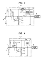
- Fig. 3 illustrates a schematic electrical configuration of an apparatus 31 for preventing corrosion of a contact, in accordance with a third embodiment of the invention.
- the contact apparatus 31 has an overheat detecting section 32 for detecting an overheat state of the power source 6, similar to the overheat detecting section 11 as shown in Figs. 1 and 2 .
- the apparatus 31 also has a current limiting section 33.
- the overheat detecting section 32 controls the current limiting section 33 disposed in a channel through which a current is supplied from the power source 6 to the switching element 12 serving as a low impedance section.
- the current limiting section 33 is implemented by a MOS transistor or a bipolar transistor.
- the current limiting section 33 When the overheat state is not detected, the current limiting section 33 becomes a low impedance to reduce a limiting amount with respect to the current supply. On the other hand, when the overheat state is detected, the current limiting section 33 becomes a high impedance to limit the current supply.
- a current supplying section which supplies the corrosion-prevention current to the input signal line 4 and has temperature characteristic for limiting the corrosion-prevention current when the temperature of the apparatus 31 rises, is implemented by the current limiting section 33.
- the power source 6 may has a function of limiting current when the temperature of the apparatus 31 rises.
- This current supplying section supplies the corrosion-prevention to the input signal line 4 and has temperature characteristic for limiting the corrosion-prevention current when the temperature of the apparatus 31 rises. Therefore, in an abnormal operation state where the corrosion-prevention current keeps flowing, the current supplying section reduces the corrosion-prevention current due to its temperature characteristic and heat generation by the corrosion-prevention current.
- an electric-current supplying means for supplying a corrosion-prevention current to the input signal line 4 and realizing temperature characteristics of restricting the corrosion-prevention current is obtained by providing the current limiting section 33.
- the current supplying means may include the function to restrict the supply of a current when the temperature is elevated as the power source 6.
- Such current supplying means is to supply a corrosion-prevention current to the input signal line 4 and provided with temperature characteristics of restricting the corrosion-prevention current when the temperature is elevated, it is able to give a protective operation by utilizing the heat generated by the current, reducing the supply of the current due to its own temperature characteristics, thereby providing a protective operation, at an abnormal time when the current is flown continuously.
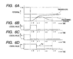
- Fig. 4 illustrates a schematic electrical configuration of an apparatus 41 for preventing corrosion of a contact, in accordance with a fourth embodiment of the invention.
- a positive temperature characteristics resistance element 42 is connected in series to the switching element 12 serving as a low impedance section.
- the positive temperature characteristics resistance element 42 is disposed on the drain side of the P channel MOS transistor, which is the switching element 12, the positive temperature characteristic resistance element 42 may be disposed on the source side thereof or disposed at a position of the current limiting section 33 shown in Fig. 3 .
- the positive temperature characteristics resistance element 42 has positive temperature characteristics, which increase in resistance value according to elevation of temperature.
- electric conductive materials such as a metal increase in resistance value according to elevation of temperature.
- thermal capacity is made small by reducing a sectional area and a corrosion-prevention current is flown continuously, electric power calculated as a product of the square of current value and a resistance value changes into heat.
- the resistance value becomes great by elevation of temperature caused by heat generation and the resistance value.
- the increase of the resistance value causes further elevation of temperature, resulting in further increase of the resistance value.
- a corrosion-prevention current is limited.
- the positive temperature characteristics resistance element 42 is a resistance element, which is inserted in series into a supply channel through which a corrosion-prevention current is flown into the input signal line 4.
- the positive temperature characteristic resistance element 42 has such a temperature characteristics that the resistance value thereof increases according to elevation of temperature.
- Such a positive temperature characteristics resistance element 42 may be implemented by a positive temperature characteristics thermistor. In comparison with using a resistance made of a metal, the thermistor can be made to have a larger temperature coefficient to improve the effect of the current limiting. If it is difficult to form the positive temperature characteristics resistance element 42 inside an LSI, the element 42maybe inserted between a terminal for connecting the input signal line 4 to an outside of an LSI and the contact 3.
- Fig. 5 illustrates a schematic electrical configuration of an apparatus 51 for preventing corrosion of a contact, in accordance with a fifth embodiment of the invention.
- the contact apparatus 51 has an OR circuit 52 to output a logical sum of a logical output of the comparator 9 and the potential of the input signal line 4.
- the output of the comparator 9 takes a high level (Hi) when the potential of the input signal line 4 is lower than the predetermined potential of the reference potential source 10, and takes a low level (Lo) when the potential of the input signal line 4 is higher than the predetermined potential.
- the OR circuit 52 If the predetermined potential is lower than a threshold level used in logical judgment by the OR circuit 52, it is possible that the potential of the input signal line 4 is lower than the threshold level even when the potential of the input signal line 4 exceeds the predetermined potential. In this state, the output of the OR circuit 52 takes a low level.
- an abnormality protecting section 53 performs a protecting operation, e.g., outputs an abnormal signal to an external terminal 54.
- Fig. 6A shows examples of the potential variation of the input signal line 4.
- Fig. 6B, 6C, and 6D show variations of the logical outputs of the corresponding comparator 9, the logic judgment result and the OR circuit 52, respectively.
- the potential of the input signal line 4 is around the power-source voltage VB until the switch 2 is changed from the on state to the off state a time tO.
- the potential of the input signal line 4 is reduced to a level lower than the predetermined potential, at the time tO.
- the logic output of the comparator 9 shown in Fig. 6B is changed from the low level to the high level, and the logic judgment result shown in 6C is changed from the high level to the low level. Therefore, the logic output of the OR circuit 52 shown in 6D remains at a high level without changing.
- the potential of the input signal line 4 increases accordingly and exceeds a detection line (the predetermined potential) at the time t1.
- a detection line the predetermined potential
- the logic output of the comparator 9 shown in Fig. 6B is changed from the high level to the low level, and the logic judgment result shown in Fig. 6C remains the low level without changing. Therefore, as shown in Fig. 6D , the logic output of the OR circuit 52 is changed from the high level to the low level. After the time t1, the output of the comparator 9 turns on the switching element 12, thereby flowing a corrosion-prevention current into the contact 3.
- the contact resistance of the contact 3 is decreased by a time t2 and it is expected that the potential of the input signal line 4 is decreased to be lower than the predetermined potential by the time t2 as shown by the dotted lines in Fig 6A .
- the abnormality protecting section 53 concludes that the contact 3 is abnormal when the output of the OR circuit 52 is at a low level after a time t3 at which a time period tw, which is longer than a time period between the time t1 and the time t2, has been elapsed from the time t1.
- the OR circuit 52 serving as an anomaly determining section compares the potential of the input signal line with the threshold level and determine as to whether or not the potential of the input signal line is abnormal on a basis of a comparison result of the comparator 9 and a comparison result of the OR section 52.
- the OR circuit 52 when the OR circuit 52 concludes that the input signal line 4 is abnormal, the OR circuit 52 outputs a low level; and when OR circuit 52 concludes that the input signal line 4 is not abnormal, the OR circuit 52 outputs a high level.
- the threshold level is set to have a sufficient margin with respect to the potential of the input signal line 4 when the contact resistance of the contact 3 is sufficiently small and the contact 3 is connected to the power-source potential side or the ground potential side. Therefore, even if the predetermined potential is set so as to detect increase of the contact resistance, the predetermined potential can be set on a side of the potential variation corresponding to decrease of the contact resistance of the contact 3 with respect to the threshold level (that is, the predetermined potential is set on the other side with respect to the threshold level in the magnitude relation).
- the apparatus 51 can conclude an abnormal operation state in which the corrosion-prevention function is nullified.
- the abnormality protecting section 53 serving as a protecting section performs the predetermined protecting operation when the OR circuit 52 serving as the anomaly determining section keeps concluding for a predetermined time period that the potential of the signal line (4) is abnormal. Therefore, when the corrosion-prevention current is flown, it is expected that the contact resistance of the contact 3 is reduced. As a result, except for the potential of the input signal line 4 when the contact 3 is in the non-contact state, it is hardly possible that the potential of the input signal line 4 keeps being on the one side with respect to the predetermined potential in the magnitude relation. If such an abnormal operation occurs, the abnormality protecting section 53 performs the predetermined protecting operation.
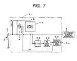
- Fig. 7 illustrates a schematic electrical configuration of an apparatus 61 for preventing corrosion of a contact, in accordance with a sixth embodiment of the invention.
- the apparatus 61 includes an analog/digital (A/D) converting section 62, which performs the A/D conversion with respect to the potential of the input signal line 4 and monitors the potential of the input signal line 4.
- a processing section 63 judges whether or not the contact 3 is corroded and whether or not the abnormal operation occurs, on a basis of the digital value converted by the A/D converting section 62.
- the corrosion judgment may be made by using the comparator 9 as described in the previous embodiment, and the abnormal operation may judged by using the processing section 63.
- the corrosion judgment may be made by using the processing section 63 and the abnormal operation may be judged as with Fig. 5 .
- At least one of functions of the comparator 9 and the abnormally determining section makes the judgment of corrosion or the judgment of anomaly on a basis of the digital value of the potential monitored by the A/D converting section 62.
- the A/D converting section 62 performs the A/D conversion with respect to the potential of the input signal line 4 and monitors the potential of the input signal line 4 and at least one of the corrosion judgment and the judgment of abnormal operation is made on a basis of the digital value of the monitored potential. Therefore, the A/D converting section 62 is used effectively to make the judgment.
- the abnormality protecting section 53 may perform the protecting operation against the abnormal operation in the following manner. That is, the abnormality protecting section 53 may further reduce an impedance of the input signal line 4, which is controlled to be a low impedance by the switching element 12 serving as a low impedance section. Since an impedance of the input signal line 4 can be reduced further at an abnormal time when the contact resistance of the contact 3 is not decreased even after the corrosion-prevention current is flown, it is possible to increase the corrosion-prevention current, which is flown into the contact 3. Further, at the abnormal time where it is difficult to restore the contact 3 because the contact resistance is not decreased after the predetermined corrosion-prevention current is flown, an impedance of the input signal line 4 can be further decreased to increase the corrosion-prevention current. If the corrosion-prevention current is increased, performance of removing an oxide can be improved. Therefore, it is expected that the contact resistance of the contact 3 is decreased.
- the abnormalityprotecting section 53 shown in Figs. 5 and 7 outputs an abnormal signal of a contact to outside of the apparatuses 61, 62 through the external terminal 54, as a protecting operation. Since the protecting operation outputs the abnormal signal of the contact to the outside, the apparatuses 51, 61 can inform the outside that anomaly occurs in the corrosion-prevention function. Therefore, a self-diagnosis function provided with a control system that uses the contact 3 to input a signal can effectively use such an abnormal signal.
- Fig. 8 illustrates a schematic electrical configuration of an apparatus 101 for preventing corrosion of a contact, in accordance with a seventh embodiment of the invention.
- the apparatus 101 is formed as an LSI having a function of selecting plural input signals. That is, the apparatus 101 includes an input circuit block 102 having plural channels.
- the apparatus 101 selects outputs of the plural channels from the input circuit block 102 by using a multiplexer 103 and makes a logical judgment by using a comparator 104 to output a judgment result.
- the input circuit block 102 has an input circuit block A 102A, an input circuit block B 102B and an input circuit block C 102C, which are different from each other in circuit configuration.
- the multiplexer 103 has an MPX 103A for selecting channels of the input circuit block A 102A, an MPX 103B for selecting channels of the input circuit block B 102B and an MPX 103C for selecting channels of the input circuit block C 102C. Outputs selected respectively by the MPX 103A, 103B and 103C are judged as logic values by comparators 104A, 104B and 104C of the comparator 104. The multiplexer 103 selects the channels in accordance with an output from the decoder 105.
- Positive power-supply voltage VB is supplied to the input circuit block 102 from a power supply 106.
- Power-supply voltage VOM5 for the logic circuit is supplied at +5V to the comparator 104 from the power supply 106.
- An overheat detecting section 107 and an anomaly detecting section 108 are disposed in the vicinity of the power supply 106. A result of the overheat detecting section 107 and that of the anomaly detecting section 108 are given to a processing section 109 to perform operations including a protecting operation of outputting an abnormal signal to an external terminal 110.
- Plural input channels of the input circuit block A 102A are connected to input terminals 111, 112, 113, ..., respectively, .
- Plural input channels of the input circuit block B 102B are connected to input terminals 121, 122, 123, ..., , respectively, .
- Plural input channels of the input circuit block C 102C are connected to input terminals 131, 132, 133, ..., respectively.
- the respective input terminals 111, 112, 113, ..., 121, 122, 123, ... and 131, 132, 133, ... are connected to contacts such as an external switch or a connector.
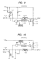
- Fig. 9 shows a schematic electrical configuration of a circuit 102Ax for preventing corrosion of a contact, provided at one channel of the input circuit block A 102A.
- An input signal line 4 is to be finally connected to the comparator 104A. Therefore, judgment as to whether a switch and a connector are turned on or off is made on a basis of the potential of the input signal line 4. It is assumed that an input terminal 11x to which the input signal line 4 is connected is used while a contact on the lower side of the power source 106 is connected thereto, as with Figs. 1 to 5 and 7 .
- a diode 8d is connected in series to the resistance 8 serving as an impedance element and prevents current from flowing in the inverse direction.
- An output of the comparator 9 is given to the switching element 12 via a delay circuit 140 and a gate circuit 141.
- the impedance of the resistance 8 is set to be higher than that of the switching element 12 at a time when the switching element 12 is turned on.
- a diode 12d is connected between the drain thereof and the input signal line 4 to prevent a current from flowing in the inverse direction.
- a diode 12e is also connected between the back gate of the P channel MOS transistor and the power source voltage VB.
- An overheat detecting signal from the processing section 109 shown in Fig. 8 are given to one input of the gate circuit 141. If overheat is not detected, the overheat detecting signal is kept at a low level.
- the overheat detecting signal is raised to a high level, thereby prohibiting the switching element 143 to turn on.
- An attenuating circuit 142 is inserted into the input signal line 4
- the gate circuit 141 is equivalent to the OR circuit.
- An attenuating circuit 142 is inserted into the input signal line 4 and serves as an output to the MPX 103A. A function of the delay circuit 140 will be described later.
- Fig. 10 shows a schematic electrical configuration of the circuit 102Bx for preventing corrosion of a contact at one channel of the input circuit block B 102B.
- the input signal line 4 is to be finally connected to the comparator 104B. Therefore, judgment as to whether a switch and a connector are turned on or off is made on a basis of the potential of the input signal line 4. Differently from Figs. 1 to 5 and 7 , it is assumed that an input terminal 12x to which the input signal line 4 is connected is used while a contact on the high side of the power source 106 is connected thereto.
- the switching element 143 serving as a low impedance section is implemented by an N channel MOS transistor.
- the switching element 143 and the resistance 144 serving as an impedance element are connected between the input signal line 4 and the ground.
- a diode 143d is connected in series between the drain of the N channel MOS transistor, which is the switching element 143, and the input signal line 4 to prevent current from flowing in the inverse direction.
- An output of the comparator 9 is given to the switching element 143 through the delay circuit 140 and the gate circuit 145.
- the overheat detecting signal from the processing section 109 shown in Fig. 8 is given to one input of the gate circuit 145. If overheat is not detected, the overheat detecting signal is kept at a low level. If overheat is detected, the overheat detecting signal is raised to a high level, to thereby prohibit the switching element 143 from turning on.
- An attenuating circuit 142 is inserted into the input signal line 4 and serves as an output to the MPX 103B.
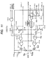
- Fig. 11 shows a schematic electrical configuration of a circuit 102Cx for preventing corrosion of a contact, at one channel of the input circuit block C 102C.
- the input signal line 4 is to be finally connected to the comparator 104C. Therefore, judgment as to whether a switch and a connector are turned on or off is made on a basis of the potential of the input signal line 4. Differently from Figs. 1 to 5 and 7 , it is assumed that a input terminal 13x to which the input signal line 4 is connected is used while not only a contact on the low side of the power source 106 but also to a contact on the high side of the power source 106 are connected thereto.
- a logic output of the comparator 9 is given to the switching element 12 via a NAND circuit 151 to which an output from the delay circuit 140 is given as one input.
- the output from an AND circuit 152 is given to the NAND circuit 151 as another input.
- the logic output of the comparator 9 is also given to the switching element 143 via a NOR circuit 153 to which the output from the delay circuit 140 is given as one input.
- the output from an OR circuit 154 is given to the NOR circuit 153 as another input.
- An output from a gate circuit 155 and an input of SEL1 are given to the AND circuit 152.
- a signal, which is obtained by inverting the output of the gate circuit 155 by an inverter 156, and a signal, which is obtained by inverting an input of SEL2 by an inverter 157, are given to the OR circuit 154.
- An input signal to SEL3 and the overheat detecting signal are given to the gate circuit 155.
- a switch 158 When the input of the SEL1 is at a high level, a switch 158 is turned on to thereby connect the resistance 8 between the input signal line 4 and the power source voltage VB as an impedance element.
- a switch 159 When the input of the SEL2 is at a high level, a switch 159 is turned on to thereby connect the resistance 144 between the input signal line 4 and the ground as an impedance element.
- switches 161 and 162 in a reference potential source 160 are turned on, respectively. Thereby, a voltage dividing circuit formed of the resistances 16, 163, and 164 is switched to change a predetermined potential used in corrosion judgment by the comparator 9.
- Fig. 12 shows relation between selected functions of the input circuit block 102C and the three selection signals SEL1, SEL2 and SEL3 shown in Fig. 11 .
- SEL1 When the SEL1 is raised to a high level, a switch can be connected to a low side, as with the input circuit block A 102A.
- SEL2 When the SEL2 is raised to a high level, a switch can be connected to a high side, as with the input circuit block B 102B.
- the SEL3 is raised to a high level, a function of preventing corrosion of a contact is turned on.
- Fig. 13 shows an operation of the delay circuit 140 shown in Figs. 9 to 11 .
- Fig. 13A shows changes in the voltage of the input signal line 4, which is input to the comparator 9.
- Fig. 11B shows the logic output of the comparator 9.
- Fig. 11C shows the output of the delay circuit 140.
- a threshold level the predetermined potential
- the delay circuit 140 has, for example, delay time td of about 5 ⁇ s.
- the delay circuit 140 When the same logic value is continuously kept for the delay time td, the delay circuit 140 outputs such a logic value after the delayed time td elapsed. Therefore, as shown in 11C, after the delay time td elapsed from the time t10, the output of the delay circuit 140 lowers to a low level. As shown by the dotted line in Fig. 11C , the high level is kept for a minimum time tmin, which is identical to the delay time td. If time from t10 to t11 is longer than the delay time td, the output of the delay circuit 140 is changed to the high level after the delay time td elapsed from the time t11.
- the circuit 101 for preventing corrosion of a contact includes channels connected to the input signal line 4, for each contact.
- the overheat detecting section 107 detects whether or not a predetermined overheat state occurs during a period where the corrosion-prevention current flows into the input signal line 4 of any of the channels. When the corrosion-prevention current does not flow, heat is almost not generated. Therefore, the overheat state does not occur.
- the processing section 109 responds to a detection result by the overheat detecting section 107.
- the processing section 109 When the overheat detecting section 107 detects the overheat state, the processing section 109 functions as an operation inhibiting section that inhibits the switching elements 12, 143, which serve as the low impedance section for a channel where the corrosion-prevention current flows, from flowing the corrosion-prevention current.
- the processing section 109 has a function of detecting whether or not the corrosion-prevention current flows in each channel and a function of raising only the overheat detecting signal for a channel where the corrosion-prevention current flows to a high level.
- the processing section 109 inhibits the corrosion-prevention current from flowing in the channel so as to perform a protecting operation for reducing the heat generation while allowing the corrosion-prevention current to flow in the other channels (the corrosion-prevention function in the other channels is prevented from being invalidated).
- the anomaly determining section 108 monitors control signals for turning on the switching elements 12, 13, 14 serving as an low impedance section the corrosion-prevention current flowing into each of the input signal lines 4 from the power source 106.
- the anomaly determining section 108 concludes that anomaly occurs. Since the corrosion-prevention current does not flow often, it is not expected that the corrosion-prevention current often flows into a plurality of contacts simultaneously. When the contact is abnormal, the corrosion-prevention operations for the respective contacts are performed independently. Therefore, there is apossibility that the corrosion-prevention operations may overlap in terms of time.
- the anomaly determining section 108 monitors the corrosion-prevention current flowing into each of the input signal lines 140 from the power source 106. When a period where the corrosion-prevention current flows in one channel of the input signal line 4 overlaps at least partly with a period where the corrosion-prevention current flows in another channel of the input signal line 4, the anomaly determining section 108 concludes that anomaly occurs. Therefore, judgment as to whether or not the contact is abnormal can be made easily.
Landscapes
- Engineering & Computer Science (AREA)
- Mechanical Engineering (AREA)
- Keying Circuit Devices (AREA)
Claims (21)
- Appareil pour éviter la corrosion d'un contact (3), l'appareil comprenant :une source de puissance (6) ;une ligne de signal (4) connectée au contact (3) ;une première résistance (8) connectée à la ligne de signal (4) ;une section de commutation qui comprend un premier commutateur (12) entre la source de puissance (6) et la ligne de signal (4), une impédance du premier commutateur (12) étant inférieure à celle de la première résistance (8) lorsque le premier commutateur (12) est fermé ;un comparateur (9) qui compare un potentiel de la ligne de signal (4) avec un potentiel prédéterminé pour déterminer si, oui ou non, le contact (3) est corrodé, le comparateur (9) délivrant un signal de commande lorsque le comparateur (9) conclut que le contact (3) est corrodé ; etune section de détection de surchauffe (11, 32, 42) qui détecte si, oui ou non, la température de l'appareil dépasse une température prédéterminée, la section de détection de surchauffe (11, 32, 42) diminuant le courant circulant à travers la section de commutation lorsque la température de l'appareil dépasse la température prédéterminée, dans lequel :la première résistance (8) et la section de commutation sont connectées en parallèle entre la source de puissance (6) et la ligne de signal (4) ; etlors de la réception du signal de commande du comparateur (9), le premier commutateur (12) est fermé.
- Appareil selon la revendication 1, dans lequel la section de détection de surchauffe (11, 32, 42) diminue le courant circulant à travers la section de commutation lorsque la température de l'appareil dépasse la température prédéterminée et que le courant circule à travers la section de commutation.
- Appareil selon l'une quelconque des revendications 1 à 2, comprenant en outre :un troisième commutateur (15), dont une extrémité est connectée au comparateur (9), dans lequel :la section de commutation comprend en outre un deuxième commutateur (13) et une deuxième résistance (14) entre la source de puissance (6) et la ligne de signal (4), le deuxième commutateur (13) et la deuxième résistance (14) étant connectés en série ;le premier commutateur (12) et le deuxième commutateur (13) sont connectés en parallèle ;une autre extrémité du troisième commutateur (15) est changée entre le premier commutateur (12) et le deuxième commutateur (13) ;une somme d'une impédance du deuxième commutateur (13) et d'une impédance de la deuxième résistance (14) est inférieure à celle de la première résistance (8) lorsque le deuxième commutateur (13) est fermé ;lorsque la section de détection de surchauffe (11) conclut que la température de l'appareil dépasse la température prédéterminée, la section de détection de surchauffe (11) change le troisième commutateur (15) d'un côté du premier commutateur vers un côté du deuxième commutateur ; etlors de la réception du signal de commande du comparateur (9), le deuxième commutateur (13) est fermé.
- Appareil selon l'une quelconque des revendications 1 à 2, dans lequel, lorsque la section de détection de surchauffe (11) conclut que la température de l'appareil dépasse la température prédéterminée, la section de détection de surchauffe (11) empêche le courant de circuler dans la section de commutation.
- Appareil selon l'une quelconque des revendications 1 à 2, dans lequel, lorsque la section de détection de surchauffe (11) conclut que la température de l'appareil dépasse la température prédéterminée, la section de détection de surchauffe (11) modifie le potentiel prédéterminé de sorte que le comparateur (9) conclue que le contact (3) n'est pas corrodé.
- Appareil selon la revendication 5, comprenant en outre :une section de détermination de potentiel de référence qui comprend une troisième résistance (22), une quatrième résistance (16), une cinquième résistance (17), et un quatrième commutateur (23) entre la source de puissance (6) et une masse, dans lequel :les troisième à cinquième résistances (22, 16, 17) sont connectées en série ;la troisième résistance (22) et le quatrième commutateur (23) sont connectés en parallèle ;le comparateur (9) utilise un potentiel d'un point intermédiaire entre la quatrième résistance (16) et la cinquième résistance (17) en tant que potentiel prédéterminé ; etlorsque la section de détection de surchauffe (11) conclut que la température de l'appareil dépasse la température prédéterminée, la section de détection de surchauffe (11) ferme le quatrième commutateur (23) pour mettre en court-circuit les deux extrémités de la troisième résistance (22).
- Appareil selon l'une quelconque des revendications 1 à 2, dans lequel :lorsque le potentiel de la ligne de signal (4) est d'un côté par rapport au potentiel prédéterminé dans une relation d'amplitude, le comparateur (9) conclut que le contact (3) est corrodé ;lorsque le potentiel de la ligne de signal (4) est de l'autre côté par rapport au potentiel prédéterminé dans la relation d'amplitude, le comparateur (9) conclut que le contact (3) n'est pas corrodé ; etlorsque la section de détection de surchauffe (11) conclut que la température de l'appareil dépasse la température prédéterminée, la section de détection de surchauffe (11) modifie le potentiel prédéterminé de sorte que le potentiel de la ligne de signal (4) soit de l'autre côté par rapport au potentiel prédéterminé dans la relation d'amplitude.
- Appareil selon l'une quelconque des revendications 1 à 2, comprenant en outre :une section de limitation de courant (33) qui limite le courant circulant dans la section de commutation lorsque la section de détection de surchauffe (32) conclut que la température de l'appareil dépasse la température prédéterminée.
- Appareil selon la revendication 8, dans lequel la section de limitation de courant (33) est disposée entre la source de puissance (6) et la première résistance (8) et entre la source de puissance (6) et la section de commutation.
- Appareil selon l'une quelconque des revendications 1 à 2, dans lequel la section de commutation comprend en outre une sixième résistance (42) connectée au premier commutateur (12) en série, la sixième résistance (42) ayant une caractéristique de température positive.
- Appareil pour empêcher la corrosion d'un contact (3), l'appareil comprenant :une source de puissance (6) ;une ligne de signal (4) connectée au contact (3) ;une résistance (8) connectée à la ligne de signal (4) ;un commutateur (12) disposé entre la source de puissance (6) et la ligne de signal (4), une impédance du commutateur (12) étant inférieure à celle de la résistance (8) ;un comparateur (9, 63) qui compare un potentiel de la ligne de signal (4) avec un potentiel prédéterminé pour déterminer si, oui ou non, le contact (3) est corrodé, le comparateur (9, 63) délivrant un signal de commande lorsque le comparateur (9) conclut que le contact (3) est corrodé ;une section de détermination d'anomalie (52, 63) qui compare le potentiel de la ligne de signal (4) avec un niveau de seuil et qui détermine si, oui ou non, le potentiel de la ligne de signal (4) est anormal sur la base d'un résultat de comparaison de la section de détection d'anomalie (52, 63) ; etune section de protection (53) qui effectue une opération de protection prédéterminée lorsque la section de détermination d'anomalie (52, 63) continue de déterminer que le potentiel de la ligne de signal (4) est anormal, pendant une période de temps prédéterminée, dans lequel :lorsqu'une résistance de contact du contact (3) augmente, le potentiel de la ligne de signal (4) change vers un côté dans une relation d'amplitude ;le potentiel prédéterminé est fixé pour être de l'autre côté par rapport au niveau de seuil dans la relation d'amplitude ;la résistance (8) et le commutateur (12) sont connectés en parallèle entre la source de puissance (6) et la ligne de signal (4) ; etlors de la réception du signal de commande du comparateur (9, 63), le commutateur (12) est fermé.
- Appareil selon la revendication 11, dans lequel :lorsque le potentiel de la ligne de signal (4) est du premier côté par rapport au potentiel prédéterminé dans la relation d'amplitude, le comparateur (9, 63) conclut que le contact (3) est corrodé ;lorsque le potentiel de la ligne de signal (4) est de l'autre côté par rapport au potentiel prédéterminé dans la relation d'amplitude, le comparateur (9, 63) conclut que le contact (3) n'est pas corrodé ;lorsque le potentiel de la ligne de signal (4) est de l'autre côté par rapport au niveau de seuil et est du premier côté par rapport au potentiel prédéterminé dans la relation d'amplitude, la section de détermination d'anomalie (52, 63) conclut que le potentiel de la ligne de signal (4) est anormal.
- Appareil selon la revendication 11, dans lequel :la source de puissance (6) comprend une première borne et une deuxième borne, dont le potentiel est inférieur à celui de la première borne ;la résistance (8) est connectée entre la première borne de la source de puissance (6) et la ligne de signal (4) ;le commutateur (12) est connecté entre la première borne de la source de puissance (6) et la ligne de signal (4) ;lorsque le potentiel de la ligne de signal (4) dépasse le potentiel prédéterminé, le comparateur (9, 63) délivre le signal de commande ;lorsque le potentiel de la ligne de signal (4) est entre le potentiel prédéterminé et le niveau de seuil, la section de détermination d'anomalie (52, 63) conclut que le potentiel de la ligne de signal (4) est anormal ; etle niveau de seuil est supérieur au potentiel prédéterminé.
- Appareil selon la revendication 11, dans lequel :la source de puissance (6) comprend une première borne et une deuxième borne, dont le potentiel est inférieur à celui de la première borne ;la résistance (8) est connectée entre la deuxième borne de la source de puissance (6) et la ligne de signal (4) ;le commutateur (12) est connecté entre la deuxième borne de la source de puissance (6) et la ligne de signal (4) ;lorsque le potentiel de la ligne de signal (4) est inférieur au potentiel prédéterminé, le comparateur (9) délivre le signal de commande ;lorsque le potentiel de la ligne de signal (4) est entre le niveau de seuil et le potentiel prédéterminé, la section de détermination d'anomalie (52, 63) conclut que le potentiel de la ligne de signal (4) est anormal ; etle niveau de seuil est inférieur au potentiel prédéterminé.
- Appareil selon l'une quelconque des revendications 11 à 14, dans lequel :la section de détermination d'anomalie (52, 63) détermine si, oui ou non, le potentiel de la ligne de signal (4) est anormal, sur la base d'un résultat de comparaison fourni par le comparateur (9, 63) et du résultat de comparaison fourni par la section de détermination d'anomalie (52, 63).
- Appareil selon l'une quelconque des revendications 11 à 15, comprenant en outre :une section de conversion A/N (62) qui convertit le potentiel de la ligne de signal (4) en une valeur numérique, dans lequel :au moins l'un du comparateur (9, 63) et de la section de détermination d'anomalie (52, 63) utilise la valeur numérique pour effectuer la comparaison.
- Appareil selon la revendication 12, dans lequel la section de protection (53) modifie le potentiel de la ligne de signal (4) de sorte que le potentiel de la ligne de signal (4) soit de l'autre côté par rapport au potentiel prédéterminé dans la relation d'amplitude, en tant qu'opération de protection.
- Appareil selon la revendication 13, dans lequel la section de protection (53) diminue le potentiel de la ligne de signal (4) de sorte que le potentiel de la ligne de signal (4) devienne inférieur au potentiel prédéterminé, en tant qu'opération de protection prédéterminée.
- Appareil selon la revendication 14, dans lequel la section de protection (53) augmente le potentiel de la ligne de signal (4) de sorte que le potentiel de la ligne de signal (4) dépasse le potentiel prédéterminé, en tant qu'opération de protection prédéterminée.
- Appareil selon la revendication 11, dans lequel la section de protection (53) délivre un signal d'anomalie à l'extérieur de l'appareil, en tant qu'opération de protection prédéterminée.
- Appareil pour empêcher la corrosion d'une pluralité de contacts (111 à 113, 121 à 123, 131 à 133), l'appareil comprenant :une pluralité de dispositifs de prévention (102Ax, 102Bx, 102Cx) prévus pour les contacts (111 à 113, 121 à 123, 131 à 133), respectivement ;une source de puissance (106) ; etune section de détermination d'anomalie (108), dans lequel :chacun des dispositifs de prévention (102Ax, 102Bx, 102Cx) comprend :une ligne de signal (4) connectée au contact (11x, 12x, 13x) ;une résistance (8, 144) connectée à la ligne de signal (4) ;un commutateur (12, 143) disposé entre la source de puissance (106) et la ligne de signal (4), une impédance du commutateur (12, 143) étant inférieure à celle de la résistance (8, 144) lorsque le commutateur (12, 143) est fermé ; etun comparateur (9) qui compare un potentiel de la ligne de signal (4) avec un potentiel prédéterminé pour déterminer si, oui ou non, le contact (11x, 12x, 13x) est corrodé, le comparateur (9) délivrant un signal de commande lorsque le comparateur (9) conclut que le contact (11x, 12x, 13x) est corrodé ; etlorsque le courant circule à travers les commutateurs (12, 143) dans au moins deux des lignes de signal (4) des dispositifs de prévention (102Ax, 102Bx, 102Cx) simultanément, la section de détermination d'anomalie (108) conclut que les lignes de signal (4) sont anormales.
Applications Claiming Priority (2)
| Application Number | Priority Date | Filing Date | Title |
|---|---|---|---|
| JP2004111030A JP3625472B1 (ja) | 2004-04-05 | 2004-04-05 | 接点腐食防止装置 |
| JP2004111030 | 2004-04-05 |
Publications (2)
| Publication Number | Publication Date |
|---|---|
| EP1585151A1 EP1585151A1 (fr) | 2005-10-12 |
| EP1585151B1 true EP1585151B1 (fr) | 2010-01-13 |
Family
ID=34373683
Family Applications (1)
| Application Number | Title | Priority Date | Filing Date |
|---|---|---|---|
| EP20050251185 Expired - Lifetime EP1585151B1 (fr) | 2004-04-05 | 2005-02-28 | Appareil pour éviter la corrosion de contact |
Country Status (6)
| Country | Link |
|---|---|
| US (1) | US7362011B2 (fr) |
| EP (1) | EP1585151B1 (fr) |
| JP (1) | JP3625472B1 (fr) |
| KR (1) | KR100679544B1 (fr) |
| CN (1) | CN100373511C (fr) |
| DE (1) | DE602005018854D1 (fr) |
Families Citing this family (27)
| Publication number | Priority date | Publication date | Assignee | Title |
|---|---|---|---|---|
| JP3625473B1 (ja) | 2004-04-05 | 2005-03-02 | 富士通テン株式会社 | 接点腐食防止方法および装置 |
| JP3625474B1 (ja) | 2004-04-05 | 2005-03-02 | 富士通テン株式会社 | 接点腐食防止回路 |
| US7486088B2 (en) | 2005-03-30 | 2009-02-03 | Fujitsu Ten Limited | Method for preventing corrosion of contact and apparatus for preventing corrosion of contact |
| JP4451855B2 (ja) | 2006-03-30 | 2010-04-14 | 富士通テン株式会社 | 信号処理装置および制御ユニット |
| US8373959B2 (en) * | 2009-09-08 | 2013-02-12 | International Business Machines Corporation | Detecting and preventing overheating in power connectors |
| JP2013525227A (ja) * | 2010-04-23 | 2013-06-20 | オーチス エレベータ カンパニー | 安全回路 |
| JP5163723B2 (ja) * | 2010-09-24 | 2013-03-13 | 株式会社デンソー | スイッチ監視装置、制御装置および制御方法 |
| JP5488420B2 (ja) * | 2010-11-18 | 2014-05-14 | 日本精工株式会社 | モータ角度検出装置 |
| DE102013016028B4 (de) * | 2012-10-31 | 2019-07-18 | Prüfrex engineering e motion gmbh & co. kg | Zündverfahren für eine Brennkraftmaschine sowie danach arbeitende Zündvorrichtung |
| CN104678254B (zh) | 2013-12-02 | 2018-08-21 | 益而益(集团)有限公司 | 电弧故障检测电路 |
| US9312680B2 (en) | 2014-05-28 | 2016-04-12 | Chengli Li | Leakage current detection interrupter with self-testing function and over-temperature protection function |
| US9778668B2 (en) * | 2014-09-30 | 2017-10-03 | Nxp Usa, Inc. | Sensed switch current control |
| JP6695660B2 (ja) * | 2015-05-21 | 2020-05-20 | 新コスモス電機株式会社 | 警報器 |
| EP3185268B1 (fr) * | 2015-12-21 | 2018-10-10 | Kone Corporation | Dispositif et procédé pour purger un contact électrique |
| DE102015016992B4 (de) | 2015-12-24 | 2017-09-28 | Audi Ag | Verfahren zum Reinigen elektrischer Kontakte einer elektrischen Schalteinrichtung und Kraftfahrzeug |
| JP7096778B2 (ja) * | 2019-02-08 | 2022-07-06 | 株式会社Subaru | スイッチシステム |
| KR102059068B1 (ko) | 2019-04-11 | 2019-12-24 | 한국화학연구원 | 철강산업의 부생가스로부터 일산화탄소의 분리 및 회수공정 |
| JP7501314B2 (ja) * | 2020-11-06 | 2024-06-18 | 株式会社アイシン | センサモジュール |
| JP7386784B2 (ja) * | 2020-12-24 | 2023-11-27 | 株式会社クボタ | 電子制御装置、作業車両および入力回路 |
| JP7844082B2 (ja) * | 2022-02-25 | 2026-04-13 | 日東工業株式会社 | 接点監視装置 |
| JP2023128888A (ja) * | 2022-03-04 | 2023-09-14 | 株式会社戸上電機製作所 | 接点監視装置、及び、接点監視方法 |
| CN114677949B (zh) * | 2022-03-29 | 2025-05-13 | 京东方科技集团股份有限公司 | 显示模组、显示装置及其工作方法 |
| CN115586426B (zh) * | 2022-08-26 | 2026-03-03 | 交控科技股份有限公司 | 信号处理系统及方法 |
| KR102644289B1 (ko) | 2023-09-18 | 2024-03-06 | 인터콘시스템스 주식회사 | 열차용 디지털 신호 입력 회로 |
| US20250244180A1 (en) * | 2024-01-29 | 2025-07-31 | Taiwan Semiconductor Manufacturing Company, Ltd. | Sensing device |
| US12548723B1 (en) * | 2024-09-27 | 2026-02-10 | Lunar Energy, Inc. | Intelligent relay package for placement in a load tray |
| KR102871351B1 (ko) | 2025-08-19 | 2025-10-15 | 인터콘시스템스 주식회사 | 열차용 디지털 신호 입력 회로 |
Family Cites Families (33)
| Publication number | Priority date | Publication date | Assignee | Title |
|---|---|---|---|---|
| US122935A (en) * | 1872-01-23 | Improvement in laying shingles | ||
| US122950A (en) * | 1872-01-23 | Improvement in ejectors for artesian wells | ||
| JPS5118189B2 (fr) * | 1972-03-24 | 1976-06-08 | ||
| JPS543338Y2 (fr) * | 1973-12-05 | 1979-02-15 | ||
| JPS5438388Y2 (fr) * | 1974-01-07 | 1979-11-15 | ||
| JPS556417Y2 (fr) * | 1974-09-11 | 1980-02-14 | ||
| JPS5686417A (en) * | 1979-12-17 | 1981-07-14 | Nissan Motor | Contact discriminating circuit |
| EP0039751A1 (fr) * | 1980-05-08 | 1981-11-18 | Imperial Chemical Industries Plc | Mesure de la résistance électrique |
| JPS58178682U (ja) * | 1982-05-25 | 1983-11-29 | オムロン株式会社 | 開閉器の接点検査装置 |
| US4540874A (en) * | 1984-01-13 | 1985-09-10 | Borg-Warner Corporation | Control system for electric water heater with heat pump external heat source |
| JPS63119116A (ja) * | 1986-11-07 | 1988-05-23 | セイコーエプソン株式会社 | 入力回路 |
| JPS63237319A (ja) * | 1987-03-26 | 1988-10-03 | 株式会社 三ツ葉電機製作所 | モ−タ制御用スイツチ接点の信頼性確保装置 |
| JPH0664963B2 (ja) * | 1988-03-01 | 1994-08-22 | 三菱電機株式会社 | 接点用電流制御装置 |
| JPH01281621A (ja) * | 1988-05-09 | 1989-11-13 | Nippon Denso Co Ltd | 車両のスイッチ用電流供給回路 |
| JPH02278620A (ja) * | 1989-04-19 | 1990-11-14 | Oki Electric Ind Co Ltd | 無電圧接点入力方式 |
| JPH02297818A (ja) | 1989-05-10 | 1990-12-10 | Mitsubishi Electric Corp | 接点の電流制御装置 |
| JPH03205710A (ja) * | 1989-12-29 | 1991-09-09 | Sumitomo Electric Ind Ltd | 自動二輪車アンチロックシステムの電源制御電磁リレーの接点浄化回路 |
| JPH0433220A (ja) * | 1990-05-28 | 1992-02-04 | Mitsubishi Electric Corp | 接点入力回路 |
| FR2673467A1 (fr) * | 1991-02-28 | 1992-09-04 | Renishaw Plc | Circuit de conditionnement de signaux pour sonde a declenchement. |
| US5289049A (en) * | 1991-08-15 | 1994-02-22 | Sony Corporation | Signal input selecting circuits |
| US5258654A (en) * | 1992-03-30 | 1993-11-02 | Eaton Corporation | Computer-checking of the position of a switch whose contacts where oxidized |
| US5243297A (en) * | 1992-04-23 | 1993-09-07 | Rohrback Cosasco Systems, Inc. | Electrical resistance temperature compensated corrosion probe with independent temperature measurement |
| JP2879807B2 (ja) | 1992-07-30 | 1999-04-05 | 矢崎総業株式会社 | スイッチの腐食防止回路 |
| JPH076650A (ja) * | 1993-06-18 | 1995-01-10 | Mitsubishi Electric Corp | 無電圧接点信号変換装置 |
| JPH0714463A (ja) | 1993-06-24 | 1995-01-17 | Matsushita Electric Ind Co Ltd | 接点信号判別装置 |
| JPH0715301A (ja) * | 1993-06-28 | 1995-01-17 | Fujitsu Ten Ltd | 遅延回路 |
| JPH08142779A (ja) * | 1994-11-18 | 1996-06-04 | Kansei Corp | 車両用スイッチ回路 |
| JPH08298041A (ja) * | 1995-04-27 | 1996-11-12 | Mitsubishi Electric Corp | 開閉器 |
| US6160402A (en) * | 1998-08-28 | 2000-12-12 | Motorola, Inc. | Method and apparatus for determining contact resistance |
| JP2001084860A (ja) * | 1999-09-10 | 2001-03-30 | Mitsubishi Electric Corp | 接点の電流制御装置 |
| JP2001216878A (ja) * | 2000-02-03 | 2001-08-10 | Toyota Motor Corp | スイッチ状態監視回路及びスイッチ |
| JP3587802B2 (ja) | 2001-05-21 | 2004-11-10 | 富士通テン株式会社 | スイッチの接点腐食防止装置 |
| DE10331158B3 (de) * | 2003-07-10 | 2005-08-25 | Robert Bosch Gmbh | Verfahren und elektronischer Schaltkreis eines elektrischen Kontaktes |
-
2004
- 2004-04-05 JP JP2004111030A patent/JP3625472B1/ja not_active Expired - Fee Related
-
2005
- 2005-02-28 DE DE200560018854 patent/DE602005018854D1/de not_active Expired - Lifetime
- 2005-02-28 EP EP20050251185 patent/EP1585151B1/fr not_active Expired - Lifetime
- 2005-03-01 US US11/067,985 patent/US7362011B2/en not_active Expired - Fee Related
- 2005-03-01 CN CNB2005100087985A patent/CN100373511C/zh not_active Expired - Fee Related
- 2005-04-04 KR KR1020050028025A patent/KR100679544B1/ko not_active Expired - Fee Related
Also Published As
| Publication number | Publication date |
|---|---|
| JP3625472B1 (ja) | 2005-03-02 |
| KR20060045486A (ko) | 2006-05-17 |
| US20050231876A1 (en) | 2005-10-20 |
| CN100373511C (zh) | 2008-03-05 |
| JP2005294198A (ja) | 2005-10-20 |
| CN1681059A (zh) | 2005-10-12 |
| EP1585151A1 (fr) | 2005-10-12 |
| KR100679544B1 (ko) | 2007-02-06 |
| DE602005018854D1 (de) | 2010-03-04 |
| US7362011B2 (en) | 2008-04-22 |
Similar Documents
| Publication | Publication Date | Title |
|---|---|---|
| EP1585151B1 (fr) | Appareil pour éviter la corrosion de contact | |
| US7550878B2 (en) | Circuit for preventing corrosion of contact | |
| JP3914004B2 (ja) | 半導体素子の過電流検出・保護装置 | |
| JP3684866B2 (ja) | 導通,遮断制御装置 | |
| US8054605B2 (en) | Power supply controller | |
| JP4579292B2 (ja) | 電力供給制御装置及びその閾値変更方法 | |
| US7410563B2 (en) | Method and apparatus for preventing corrosion of contact | |
| JP2020205553A (ja) | 半導体装置 | |
| JP2006024997A (ja) | 半導体スイッチの制御装置 | |
| JP4836694B2 (ja) | 電力供給制御装置 | |
| EP2079165B1 (fr) | Système de diagnostic et de commande de charge | |
| JP4271169B2 (ja) | 半導体装置 | |
| KR101025535B1 (ko) | 단락보호회로를 구비한 스위치 제어 회로 | |
| JP2005027380A (ja) | インテリジェントパワーデバイス及びその負荷短絡保護方法 | |
| US7265958B2 (en) | Overcurrent protection circuit and semiconductor apparatus | |
| JP2000058756A (ja) | 双方向電子スイッチ | |
| JP2005150920A (ja) | 出力回路 | |
| JP2004248452A (ja) | 過電流保護回路 | |
| JP7354637B2 (ja) | 半導体装置 | |
| CN118975132A (zh) | 用于控制晶体管的控制系统、包括该控制系统的电动车辆、用于控制该晶体管的方法 |
Legal Events
| Date | Code | Title | Description |
|---|---|---|---|
| PUAI | Public reference made under article 153(3) epc to a published international application that has entered the european phase |
Free format text: ORIGINAL CODE: 0009012 |
|
| AK | Designated contracting states |
Kind code of ref document: A1 Designated state(s): AT BE BG CH CY CZ DE DK EE ES FI FR GB GR HU IE IS IT LI LT LU MC NL PL PT RO SE SI SK TR |
|
| AX | Request for extension of the european patent |
Extension state: AL BA HR LV MK YU |
|
| 17P | Request for examination filed |
Effective date: 20060223 |
|
| AKX | Designation fees paid |
Designated state(s): DE FR GB |
|
| GRAP | Despatch of communication of intention to grant a patent |
Free format text: ORIGINAL CODE: EPIDOSNIGR1 |
|
| GRAS | Grant fee paid |
Free format text: ORIGINAL CODE: EPIDOSNIGR3 |
|
| GRAA | (expected) grant |
Free format text: ORIGINAL CODE: 0009210 |
|
| AK | Designated contracting states |
Kind code of ref document: B1 Designated state(s): DE FR GB |
|
| REG | Reference to a national code |
Ref country code: GB Ref legal event code: FG4D |
|
| REF | Corresponds to: |
Ref document number: 602005018854 Country of ref document: DE Date of ref document: 20100304 Kind code of ref document: P |
|
| PLBE | No opposition filed within time limit |
Free format text: ORIGINAL CODE: 0009261 |
|
| STAA | Information on the status of an ep patent application or granted ep patent |
Free format text: STATUS: NO OPPOSITION FILED WITHIN TIME LIMIT |
|
| 26N | No opposition filed |
Effective date: 20101014 |
|
| REG | Reference to a national code |
Ref country code: FR Ref legal event code: PLFP Year of fee payment: 12 |
|
| REG | Reference to a national code |
Ref country code: FR Ref legal event code: PLFP Year of fee payment: 13 |
|
| PGFP | Annual fee paid to national office [announced via postgrant information from national office to epo] |
Ref country code: FR Payment date: 20170112 Year of fee payment: 13 Ref country code: DE Payment date: 20170221 Year of fee payment: 13 |
|
| PGFP | Annual fee paid to national office [announced via postgrant information from national office to epo] |
Ref country code: GB Payment date: 20170222 Year of fee payment: 13 |
|
| REG | Reference to a national code |
Ref country code: DE Ref legal event code: R119 Ref document number: 602005018854 Country of ref document: DE |
|
| GBPC | Gb: european patent ceased through non-payment of renewal fee |
Effective date: 20180228 |
|
| REG | Reference to a national code |
Ref country code: FR Ref legal event code: ST Effective date: 20181031 |
|
| PG25 | Lapsed in a contracting state [announced via postgrant information from national office to epo] |
Ref country code: DE Free format text: LAPSE BECAUSE OF NON-PAYMENT OF DUE FEES Effective date: 20180901 |
|
| PG25 | Lapsed in a contracting state [announced via postgrant information from national office to epo] |
Ref country code: FR Free format text: LAPSE BECAUSE OF NON-PAYMENT OF DUE FEES Effective date: 20180228 Ref country code: GB Free format text: LAPSE BECAUSE OF NON-PAYMENT OF DUE FEES Effective date: 20180228 |