EP1580393A2 - Porte - Google Patents
Porte Download PDFInfo
- Publication number
- EP1580393A2 EP1580393A2 EP05002295A EP05002295A EP1580393A2 EP 1580393 A2 EP1580393 A2 EP 1580393A2 EP 05002295 A EP05002295 A EP 05002295A EP 05002295 A EP05002295 A EP 05002295A EP 1580393 A2 EP1580393 A2 EP 1580393A2
- Authority
- EP
- European Patent Office
- Prior art keywords
- door leaf
- door
- closed position
- door according
- arrangement
- Prior art date
- Legal status (The legal status is an assumption and is not a legal conclusion. Google has not performed a legal analysis and makes no representation as to the accuracy of the status listed.)
- Granted
Links
Images

Classifications
-
- E—FIXED CONSTRUCTIONS
- E06—DOORS, WINDOWS, SHUTTERS, OR ROLLER BLINDS IN GENERAL; LADDERS
- E06B—FIXED OR MOVABLE CLOSURES FOR OPENINGS IN BUILDINGS, VEHICLES, FENCES OR LIKE ENCLOSURES IN GENERAL, e.g. DOORS, WINDOWS, BLINDS, GATES
- E06B7/00—Special arrangements or measures in connection with doors or windows
- E06B7/16—Sealing arrangements on wings or parts co-operating with the wings
- E06B7/22—Sealing arrangements on wings or parts co-operating with the wings by means of elastic edgings, e.g. elastic rubber tubes; by means of resilient edgings, e.g. felt or plush strips, resilient metal strips
- E06B7/23—Plastic, sponge rubber, or like strips or tubes
- E06B7/2316—Plastic, sponge rubber, or like strips or tubes used as a seal between the floor and the wing
-
- E—FIXED CONSTRUCTIONS
- E05—LOCKS; KEYS; WINDOW OR DOOR FITTINGS; SAFES
- E05D—HINGES OR SUSPENSION DEVICES FOR DOORS, WINDOWS OR WINGS
- E05D15/00—Suspension arrangements for wings
- E05D15/16—Suspension arrangements for wings for wings sliding vertically more or less in their own plane
- E05D15/24—Suspension arrangements for wings for wings sliding vertically more or less in their own plane consisting of parts connected at their edges
-
- E—FIXED CONSTRUCTIONS
- E05—LOCKS; KEYS; WINDOW OR DOOR FITTINGS; SAFES
- E05Y—INDEXING SCHEME RELATING TO HINGES OR OTHER SUSPENSION DEVICES FOR DOORS, WINDOWS OR WINGS AND DEVICES FOR MOVING WINGS INTO OPEN OR CLOSED POSITION, CHECKS FOR WINGS AND WING FITTINGS NOT OTHERWISE PROVIDED FOR, CONCERNED WITH THE FUNCTIONING OF THE WING
- E05Y2800/00—Details, accessories and auxiliary operations not otherwise provided for
- E05Y2800/71—Secondary wings, e.g. pass doors
-
- E—FIXED CONSTRUCTIONS
- E05—LOCKS; KEYS; WINDOW OR DOOR FITTINGS; SAFES
- E05Y—INDEXING SCHEME RELATING TO HINGES OR OTHER SUSPENSION DEVICES FOR DOORS, WINDOWS OR WINGS AND DEVICES FOR MOVING WINGS INTO OPEN OR CLOSED POSITION, CHECKS FOR WINGS AND WING FITTINGS NOT OTHERWISE PROVIDED FOR, CONCERNED WITH THE FUNCTIONING OF THE WING
- E05Y2900/00—Application of doors, windows, wings or fittings thereof
- E05Y2900/10—Application of doors, windows, wings or fittings thereof for buildings or parts thereof
- E05Y2900/106—Application of doors, windows, wings or fittings thereof for buildings or parts thereof for garages
Definitions
- the invention relates to a gate with a between a closed position and a Opening position movable and a plurality of respect.
- a door Parallel to each other Tilting axes against each other tiltable Torblattmaschinen having door leaf, a door integrated in the door leaf with an approximately perpendicular to the tilt axes extending pivot axis with respect.
- Torblattebene Door leaf In the direction of the tilt axes adjacent Torblattianon pivotable, in its closed position in a recess of the door leaf recorded and preferably arranged in the closed position approximately in the Torblattebene Door leaf and a deformation of the door blade counteracting stabilization arrangement and a safety device for gates of this type.
- Gates with a plurality of respect. Parallel to each other tilting axes against each other tiltable Torblattianon gateways are in Form of garage doors and in the form of industrial gates for closing passages used in garages and industrial halls.
- the door leaf is common in the closed position about in a vertical plane and in the open position on Head arranged approximately in a horizontal plane.
- To guide the door leaf movement between the closed position and the open position are usually guide rails with an approximately rectilinear and approximately parallel to the side Torblattrand in the closed position extending vertical section, another approximately rectilinear and approximately parallel to the side Torblattrand in the open position extending horizontal section and a the two rectilinear sections interconnecting arcuate portion intended.
- To enable the Torblattterrorism along the arcuate portion the door leaf elements of the door leaf are perpendicular to the guide rails extending tilt axes against each other tilted connected to each other.
- the door leaf of such constructions usually made a plurality of axes running colinearly with respect to the tilt axes relative to each other tiltable door leaf elements.
- the gate known from the cited document has at least one parallel to the Tilting axes horizontally displaceable push pin in the bottom region of the frame arrangement or of the door leaf, which in the locking position in an opening engages in the frame or the door leaf.
- the locking device comprises formed stabilizing arrangement of the known gate to a parallel to Swivel axis extending axis pivotable locking element, which when moving of the thrust pin is pushed into the opening of the thrust pin to the side, this Locking element with a detent-like end behind the edge of an abutment grasps the door or gate segment and locks in place there.
- This should be a movement of arranged on both sides of the door leaf door leaf elements in the horizontal direction in the Main level of the gate can be prevented, so as to the above-described mounting a gap between the door leaf and frame or adjacent door leaf elements during to prevent the opening or closing movement of the door leaf.
- the Invention the object of a structurally simple executable goal of the beginning to provide said type, on the one hand, the requirements for an escape route fulfilled and on the other hand has a sufficient overall stability.
- this object is achieved by a development of the known goals solved, which is characterized essentially in that the stabilizing arrangement one in the closed position of the door leaf on the bottom of the closed with the door leaf Opening resting, the lower edge of the door leaf receiving recess forming and preferably adjacent to the recess in the direction of the tilt axes Torianon fastened threshold element whose height in the direction of Pivot axis at least in the region of its preferably approximately parallel to the tilt axes extending edges less than 20 mm, preferably less than 10 mm, more preferably less than 8 mm, in particular 5 mm or less.
- This invention is based on the finding that in the conventional Gates of the type described above observed deformations of the door leaf Bending in a direction perpendicular to the Torblattebene direction on the one hand and by spreading of the door leaf receiving recess adjacent door leaf elements on the other hand by structurally separate elements of the stabilizing arrangement can be prevented, with only the sagging of the door leaf in a direction perpendicular to the Torblattebene counteracting element the stabilization arrangement in the region of the lower edge of the receiving the door leaf Recess must be arranged, while the observed spreading of the Recess adjacent Torblattemia also by a above the recess arranged stabilizing element and in the simplest case even by an upper door leaf element can be prevented.
- the threshold element with a particularly low height of less than 20 mm, preferably less than 10 mm, more preferably less than 8 mm, in particular 5 mm or less of the Area of parallel to the tilt axes extending edges are executed. by virtue of This small height of the threshold element there are no concerns when using the integrated in the door leaf the wicket door of the invention as an escape door.
- the width of the threshold element in this direction suitably larger than the Torblattdicke in this direction. It is expediently more than 150%, preferably more than 200%, more preferably more than 250 % of the Torblattdicke, in particular 300% of the Torblattdicke or more, wherein the Threshold preferably extends over the entire Torblattdicke, so on the one hand to achieve a better stabilization and on the other hand an excessive overhang over to avoid the door leaf thickness. With regard to the achievement of a balanced compromise between stability on the one hand and costs and space requirements on the other the width of the threshold element expediently less than 350%, preferably 300% or less of the door leaf thickness.
- the width of the threshold element may be to obtain the desired stabilizing effect regardless of the Torblattdicke a value of 60 mm or more, suitably 80 mm or more, preferably 100 mm or more, more preferably 120 mm or more, in particular 140 mm or more.
- a material with a tensile strength of More than 120 N / mm 2 , in particular more than 370 N / mm 2 , more preferably more than 540 N / mm 2 formed threshold element in the region of at least one of its preferably approximately parallel to the tilting axes extending edges to form a tilting axis extending in the direction
- Receiving for a sealing element at its in the closed position of the door leaf lower boundary surface is bent back on itself.
- the threshold element has a tensile strength of less than 1000 N / mm 2 , preferably less than 900 N / mm 2 , in particular less than 750 N / mm 2 , wherein the tensile strength range of 540 to 750 N / mm 2 has proved to be particularly favorable.
- the threshold element may be approximately parallel to the Kippachsen extending and in the firing position downwardly open channel between have its lateral edges, for receiving a mounting portion of the sealing element can be used.
- the threshold element is less than 22 mm, preferably less than 12 mm, more preferably less than 10 mm, in particular 7 mm or less, also even if threshold elements with a higher overall height, the formation of a Tripping edge by providing corresponding ramp-shaped wall elements can still be prevented.
- Threshold elements according to the invention gates are preferably made of a material high tensile strength, such as steel, with a material thickness of 3 mm or less, preferably made 2 mm or less, if necessary by additional cranks or bending can be stabilized. In the context of the invention, however, is also on the Use of threshold elements made of other materials, such as composites, e.g. glass fiber reinforced plastic, or Kevlar, possibly in conjunction with steel, thought. With Material thicknesses of 3 mm or less or 2 mm or less may be threshold elements with a serving for receiving a sealing element channel while avoiding an excessive height of the threshold element are produced.
- threshold elements made of a material with a material thickness of 7 mm or less, in particular 6 mm or less, especially preferably 5 mm or less conceivable. In this case, a material thickness of about 5 mm particularly useful.
- the sealing element one preferably at least partially in the channel of the threshold element recorded attachment portion and at least one, preferably two or more, starting from it in opposite directions obliquely downwards have sloping sealing tabs.
- a particularly good sealing effect is obtained when at least one edge remote from the attachment portion of at least one sealing flap at least in sections in the closed position is bent upwards because of this Edge then by conditioning the sealing lobe at the bottom of the opening to be closed is urged against the lower boundary surface of the threshold element, so as a to provide reliable sealing between the floor and the threshold element.
- the Sealing element preferably in the region of its attachment portion of an optionally open at the top and passing approximately in the direction of the tilting axes cable channel is interspersed. In this cable channel, a connection cable between individual elements of a security device be inserted for a gate according to the invention.
- the desired stabilizing effect is achieved particularly reliably when the threshold element in the closed position lower edges of the recess in Direction of tilting axes adjacent Torblattemia is attached.
- the individual Torblattemia independent in mass production made uniform from their later place of use, it has proved to be proven particularly favorable when, for fixing the threshold element on the one hand at the bottom of one of the Torblattemia and on the other hand at an upper boundary surface the threshold element attached fastener is used.
- a cohesive attachment, such as bonding also used come like a positive fastening, such as screwing.
- a combination of both types of attachment possibly with additional stabilization by a non-positive attachment, for use.
- the width of the threshold elements according to the invention Gates in a direction perpendicular to the Torblattebene direction preferably larger than the door leaf thickness.
- the width of the threshold elements according to the invention must be prevented that people in the door leaf closed position on the Threshold can stand and after an opening movement with the door leaf be pulled up.
- the desired stabilizing effect it has proved to be advantageous when the fastener one in a parallel to the tilt axes extending below open Dent in the lower edge of the door leaf elements recorded projection. Further stabilization can be achieved if the fastener between an a voltage applied to an inner surface of the door leaf wall element and the projection formed receptacle for receiving a at the bottom of the Torblattiatas having arranged projection.
- the door leaf according to the invention advantageously gates also a plurality of collinear with respect to the tilt axes extending Axes against each other tiltable door leaf elements.
- the Door leaf elements in a plane perpendicular to the tilt axes cutting plane about the have the same shape as the door leaf elements. In this case is usually between the lower edge of the door leaf and the threshold element one of the height of the fastening element appropriate distance released. A tight seal in the area the lower edge of the door leaf is then accessible, if at the in the door leaf closed position lower door leaf element, a transition element is mounted in the Door leaf closed position between the threshold element and the lower door leaf element is arranged. In this case, the transition element in a door leaf closed position the voltage applied to the adjacent Torblattmaschinen threshold element fitting Have sealing arrangement. To provide a reliable seal Such a sealing arrangement expediently in the door leaf closed position on a front boundary surface of the threshold element fitting sealing element and / or in the door leaf closed position at an upper boundary surface of Threshold element fitting sealing element.
- the threshold element has proven to be particularly useful when the transition element at least in the area of the Torblattau builtseite in a direction perpendicular to the tilt axes extending cutting plane has approximately the same shape as the fastener, i.e. a sloping towards the outer edge of the threshold element upper Having boundary surface portion, in addition, also in the direction of the Provided inside the threshold element sloping upper boundary surface portion can be.
- the color designs matched by transition element and fastener in particular same, more preferably according to the color scheme conventional Sealing arrangements, be executed in black.
- the transition element expediently in a recess in the lower edge of the lower door leaf element engaging projection.
- the threshold element a gate according to the invention the bending of the door leaf in a perpendicular to Torblattebene opposing direction counteracted.
- the bending of the door leaf in a parallel to the pivot axis extending direction can with the help of an above arranged the recess receiving the door leaf and spanning the recess Stabilizing element to be counteracted.
- This stabilizing element can in a particularly simple embodiment of the invention by an above the door leaf receiving recess arranged through Torblattelement be realized.
- the stabilizing element has to obtain the desired Stabilization effect expediently one in the door leaf closed position approximately in a vertical plane arranged boundary surface, which in a particular preferred embodiment of the invention of a substantially planar Layer is formed of a material of high tensile strength.
- gates can be used with particularly thin sealing arrangements come, with a lower edge of the door leaf with a not by a sealing element protected portion of the threshold element in the course of the closing movement can hit an object or a person. In this case, despite the known Kraftbegrenzung still considerable property damage or injury of Persons occur.
- Such a safety device is that of the closing movement leading edge of the door leaf track already monitored without contact, before this leading edge reaches the corresponding track section. Then If necessary, the drive can be switched off before the door leaves on in the area of the door Movement path arranged object or a person there exists.
- a Such safety device can not only with gates according to the invention with integrated Wicket door, but also in conventional gates without wicket door used. However, the use of such safety devices is particularly useful gates according to the invention with integrated wicket door and one at the lower boundary surface the threshold element arranged sealing arrangement of small thickness.
- the securing device advantageously has at least a transmitter arrangement for delivering wirelessly transmitted signals in one approximately parallel to the tilt axis extending direction and at least one receiver arrangement for receiving the signals emitted by the transmitter arrangement, the transmitter arrangement and the receiver arrangement expediently in the range mounted opposite side edges of the door leaf, preferably on Door leaf are attached.
- the signals of the transmitter arrangement are expediently parallel to the voriaufenden in the Schüeß Gay edge of the door leaf in the direction of Dismissed closing movement in front of this edge for objects and persons to gather can be before the edge of the door leaf in the course of the closing movement on it incident.
- the transmitter arrangement for Outputting signals along two or more in a plane perpendicular to the door leaf plane Direction against each other staggered and preferably approximately parallel operable to the tilt axes extending signal paths may be a moving with the threshold element signal grid in the of the Threshold element through space to be created, with the interruption only a grid element formed by the individual signal paths in the course of the Torblattieri be exploited to generate a shutdown signal for the door drive can.
- the door leaf goes through during the closing movement and so that the leading edge during the closing movement of the door leaf an arcuate Section of a predetermined path between a vertical guide rail section and a horizontal guide rail section.
- the impact of the leading during the closing movement Torblattrandes be reliably prevented on objects or persons.
- At least an element of the transmitter assembly such as one, for example, in the form of a light source realized transmitter element or realized for example in the form of a mirror Deflection element and / or at least one element of the receiver assembly, such as a in the form of a photodiode realized receiver element or in the form of a mirror realized deflecting element via a coupling arrangement about an approximately parallel to the Tilting axes extending pivot axis is pivotally mounted on the door leaf.
- the coupling arrangement and thus also the attached element of the receiver assembly and / or the transmitter assembly attached to an inner boundary surface of the door leaf is to allow access to the coupling arrangement and the elements attached thereto is prevented from the outside when the door leaf is closed.
- the invention may provide the desired arrangement of the coupling assembly fastened element of the receiver assembly and / or the transmitter assembly in one Vertical plane reached with the leading edge during the closing movement of the door leaf be when the coupling arrangement in the area of the closing movement leading edge with respect to a parallel to the tilt axes extending pivot axis pivotable on the door leaf, in particular an inner boundary surface of the door leaf having attached coupling lever which in at least one pivotal position the engages in the closing movement leading edge of the door leaf.
- This can be the Coupling lever two or more, each in a direction perpendicular to the tilt axes extending Level an angle of less than 180 ° with each other, preferably in the have substantially rectilinear lever segments.
- the pivoting movement of the coupling arrangement be limited by means of a suitable stop assembly so that the coupling arrangement not too far from the leading in the closing movement of the door leaf Swings away edge and is achieved that attached to the coupling arrangement Element of the transmitter arrangement and / or receiver arrangement also in the region of the arcuate Section of the predetermined path approximately in a vertical plane with the the closing movement leading edge of the door leaf is arranged.
- the pivoting movement of the coupling arrangement results in that the coupling arrangement when hitting the floor of the room to be closed with the door leaf or upon impact with an object or part of person lying on the ground only can still dodge to a limited extent. This can damage the coupling arrangement, the objects lying on the floor and / or a personal injury to lead.
- the safety device according to the invention gates can be particularly easily avoided be when the pivotally mounted on the door leaf coupling lever for a recording at least one transmitter element, at least one receiver element and / or at least one deflecting element designed housing. Because of this Housing can use the mentioned elements without affecting their functionality be protected from damage. To obtain the desired function of monitoring one of the threshold element to be traversed space, it has to be special proven favorable, when the housing in the pivotally mounted on the door leaf Lever segment attached lever segment is arranged. To ensure the Functionality when using signal gratings with two or more longitudinally parallel to each other extending signal paths propagating signals, it has been useful proven when the housing has two or more windows for each at least one longitudinally having a signal propagating signal.
- the safety device according to the invention gates can be made very compact be when a pivot axis facing away from the end region of the pivotable with respect to the lever segment attached to the door leaf segment arranged on the door leaf lever segment is arranged offset in the direction of the tilting axis, because in this arrangement, the staggered lever segment in the door leaf closed position can be arranged next to the door leaf.
- one attached to the coupling arrangement Element of the securing device expediently when reaching the closed position of the door leaf automatically into the interior of the closed space with the door leaf pivoted, wherein the coupling arrangement expediently to dodge in one the closing movement opposite direction when hitting an obstacle in the final phase of the closing movement is designed.
- a security device for a gate according to the invention is in essentially by a transmitter element and / or receiver element and one to the pivotable Coupling of this element to a door leaf designed coupling arrangement characterized in that the transmitter element is a light source and the receiver element may comprise a photodiode and the coupling arrangement comprises a coupling lever having two or more possibly hingedly interconnected lever segments can.
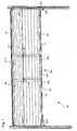
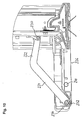
- the door leaf generally designated 10 in FIG. 1, comprises a plurality of door leaf elements, of which in the closed position lower door leaf elements 12 and 14 in the position shown in Fig. 1 are arranged one above the other, as well as a total with 100 designated and integrated into the door leaf door leaf with two in Fig. 1 above the other arranged door leaf elements 102 and 104.
- the door leaf elements 12 and 14 are also as the door leaf elements 102 and 104 by means of indicated at 30 hinged executed Joints with respect to the tilt axes 20 against each other tilted.
- the lower edge of the door leaf 100 receiving recess in the door leaf 10 is from one at the bottom of on opposite sides of the recess arranged door leaf elements 12 fixed threshold element 50 limited.
- the attachment of the threshold element 50 to the door leaf elements 12 takes place in the in Fig. 1 illustrated embodiment of the invention by means of fasteners 40, which on the one hand at the upper boundary surface of the threshold element 50 and On the other hand, are attached to the lower boundary surface of the Torblattemia 12.
- at the embodiment of the invention shown in Fig. 1 is a between the lower Edge of the door leaf element 102 and the threshold element 50 released clearance bridged by a transition element 140.
- the width B of the threshold element 50 is in one perpendicular to the door leaf plane direction greater than the thickness D of the door leaf in this direction.
- the width B of the threshold element is 123.5 mm, while the thickness D of the door leaf 42 mm.
- threshold elements can also be used lesser or greater width and door leaves used with lesser or greater thickness become.
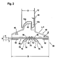
- Fig. 2 extends the threshold element over the entire Torblattdicke and stands both on the Torblattinnenseite as well as on the Torblattau typeseite on the Torblatt out.
- the parallel to the tilting axes 20 extending edges 52 of the threshold element 50 are for obtaining a greater stabilizing effect and for forming a receptacle 60 for a mounted on a lower boundary surface of the threshold element 50 Seal member 70 folded back on itself.
- the sealing member 70 includes a mounting portion 72 and in total four sealing tabs 74 and 76, wherein the outer sealing tabs 76 as well as the inner Sealing tabs 74 extend obliquely downward in opposite directions.
- the edges 78 of the sealing tabs 76 facing away from the attachment section 72 follow bent outside and above, so as to better sealing effect when hitting the Ensure the floor of the room to be closed.
- the attachment portion 72 of the parallel to the tilt axes over the entire door leaf width extending sealing element 70 is located in a bottom open, centrally located between the edges 52 and extending parallel to the tilt axes over the entire Torblattbreite channel 54 arranged in the threshold element 50.
- the lateral boundary walls 56 of the channel 54 fall ramped toward the lateral edges 52 of the threshold element 50, wherein in the embodiment of the invention shown in the drawing include an angle ⁇ of about 45 ° with a horizontal plane.
- Around lateral edges 52 is the height h of the threshold element 50 in the drawing illustrated embodiment of the invention about 5 mm.
- the total height H in the range of the channel 54 is in the embodiment of the invention shown in the drawing about 7 mm.
- the depth T of the receptacle 60 is about 3 mm.
- the threshold element 50 of the embodiment of the invention shown in FIG is made entirely of a steel sheet with a thickness of about 2 mm.
- the Threshold element extends, as can be seen in Fig. 1, over the entire door leaf width.
- Seal member 70 with a central mounting portion 72' and two of them starting in opposite directions extending obliquely downwards Sealing tabs 76 'are shown, each of which facing away from the attachment portion 72' Edge 78 'is bent upwards.
- a Line 80 may be included.
- the threshold element 50 is on the one hand with the aid of a the upper boundary surface of the threshold element 50 and on the other hand at the bottom Edge of the door leaf element 12 fastened fastener 40 to the door leaf element 12 attached.
- To obtain the desired stabilizing effect is one at the top Edge of the fastener 40 provided projection 42 in one in the lower Received edge of the door leaf element 12 provided recess 12a.
- One in the area the Torblattinnenseite at the bottom of the Torblattiatas 12 downwardly projecting Projection 12b is in a between one on an inner surface of the Torblattiatas 12 adjacent wall member 44 and the projection 42 formed receptacle arranged.
- the fastener 42 has a starting from the Torblattau touchseite in the closed position obliquely downward toward an outside Edge of the threshold element 50 sloping upper boundary surface portion 46th and one of the door leaf inner side in the closed position obliquely downward in the direction on an inside edge of the threshold element 50 sloping upper boundary surface portion 48 on.
- the upper boundary surface portion 46 in the closed position an angle ⁇ of about 25 ° with a horizontal plane.
- the upper Boundary surface portion 48 closes in the closed position an angle ⁇ of about 20 ° with a horizontal plane.
- the lower door leaf element 102 in a direction perpendicular to the tilt axes extending cutting plane about the same shape as the lower door leaf element 12.
- the between the lower edge of the door leaf element 102 and the threshold element 50 released distance is bridged by a transition element 140 whose Cross-sectional shape starting from the inner boundary surface of the door leaf element 102nd in the direction of the outer edge of the threshold element 50 approximately the cross-sectional shape of Fastener 40 corresponds.
- the transition element 140 has at its upper edge of a projection 142 which in a recess 102 a in the lower Edge of the door leaf element 102 is received.
- a receptacle 146 is formed in which a downwardly projecting projection 102b received in the region of the inner boundary surface of the door leaf element 102 is.
- the fastener 40 also has the transition element 140 one in the direction of the outer edge of the threshold element 50 obliquely downwards sloping upper boundary surface portion 146. With regard to the desired Opening movement of the door leaf, the transition element 140 is not on the threshold element 50 attached.
- two sealing elements 172 and 174 are arranged, of which the sealing element 172 in the door leaf closed position at a front boundary surface of Threshold element 50 abuts while the sealing member 174 at the through the channel 54 formed upper boundary surface of the threshold element is applied.
- the door leaf element 102 as well as the door leaf element 12 in the form of a Insulating material, such as PU foam, at least partially filled double-shelled panel formed, wherein the two shell elements in the area folded back on itself Edge sections are positively connected with each other.
- the transition element 144 is as well as the fastener 40 in the region of this folded back on itself Edge portions of the panel shell by means of not shown in the drawing Screws on the door leaf element 12 and
- the attachment takes place with the help of in the wall elements 44 and 144 provided oblong holes, wherein the slots approximately parallel to the Swivel axes and perpendicular to the tilt axes can extend.
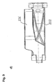
- the stabilization arrangement of a door according to the invention also at least one above the door leaf 100 receiving recess arranged and have the recess spanning stabilizing element 90, in the embodiment of the invention shown in Fig. 5 of a steel sheet with a material thickness of about 2 mm is formed and overall in the form of a toward is executed on the inner boundary surface of the door leaf 10 open channel.
- the channel bottom 92 extends in the closed position of the door leaf 10 approximately in a vertical plane.
- the channel walls 94 extend approximately perpendicular to the channel bottom 92.
- the channel bottom 92 facing away from the edges of the channel walls 94 to form mounting flanges 96 bent outwards.
- the flanges 96 are of screws 98th penetrated, which in the range of bent back on itself edge portions of the Shells of the upper door leaf element can be accommodated in this door leaf element.
- the stabilizing element 90 Received through the channel bottom 92 and the flange-shaped mounting portions 96 the stabilizing element 90 overall a particularly high stability with respect to deflections in the direction indicated by the arrow P in Fig. 5 direction of gravity.
- the stabilizing element 90 at the inner Clamping surface of the door leaf 10 attached.
- this complete door leaf element as additional Stabilizing element can be used. Furthermore, in embodiments of the With reference to Fig. 5 described type also thought of the additional stabilizing element 90 to integrate into the Torblattelement so as to inwardly projecting parts avoid.
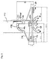
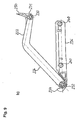
- the embodiment of the invention shown in Fig. 1 comprises a non-contact working safety device with a in the region of the right edge of the door leaf arranged below the leading edge in a closing movement of the door leaf Transmitter arrangement 210 and one in the region of the left edge of the door leaf below the leading edge during the closing movement arranged receiver arrangement 250.
- the transmitter assembly 210 a light source and the Receiver assembly 250 having a photodiode.
- the transmitter assembly 210 is via a coupling arrangement 220 coupled to the lower edge of the Torblattiatas 12, while the receiver assembly 250 via a coupling arrangement 260 to a lower edge of the Torblattettis 12 is coupled.
- the invention is also thought of only a deflection arrangement via corresponding coupling arrangements to the Torblattmaschine 12 koppein and with fixedly mounted transmitter elements and receiver elements such as light sources and photodiodes.
- the Umlenkanssenen be realized in the form of simple mirror.
- the transmitter arrangement 210 according to FIG. 1 is for outputting signals in a signal cone operable with an opening angle of more than 2 °. This will ensure that the receiver assembly 250 also in torsions of the door leaf of the transmitter assembly 210 can receive received signals, if no signal interruption through an obstacle.
- the transmitter element 210 is the same as the receiver element 250 with the aid of Coupling arrangement 220 and 260 about an approximately parallel to the tilt axes 20 extending Pivoting pivotally mounted on the door leaf 10.
- the for this purpose usable coupling arrangements will be described below with reference to FIG. 6 using the example the coupling arrangement 220 described.
- the coupling arrangement 220 is in the form of a formed three segments 222, 224 and 226 comprehensive coupling lever.
- the coupling lever 220 is a total of about a parallel to the tilting axes 20 extending pivot axis 230 pivotally attached to the lower edge of the door leaf 10.
- lever segment 222 To the door leaf 10 adjacent lever segment 222 is associated with a stop 231, with a Pivoting movement of the lever segment 222 in the direction indicated by the arrow S. Pivoting direction is limited away from the lower edge of the door leaf 10 away.
- the lever segment 222 closes with the adjoining lever segment 224 an obtuse angle ⁇ of about 130 °.
- the lever segments 222 and 224 are made in one piece.
- the lever segment 226 is a pivot axis 232 extending parallel to the tilting axes 20 coupled to the lever segment 222 facing away from the end of the lever segment 224.
- the lever segment 224 is replaced by a Stop 234 limited. In the embodiment of the invention shown in Fig. 6 is the maximum pivot angle ⁇ 'of the lever segment 226 with respect to the lever segment 224 110 °.
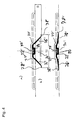
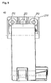
- Figs. 9 and 10 is a coupling arrangement for a safety device represented according to a further embodiment of the invention.
- Fig. 9a a perspective view of the coupling arrangement
- Fig. 9b a side view of the coupling arrangement
- 9c a view of the coupling arrangement from the rear
- Fig. 9d a view of the coupling arrangement from below.
- Figs. 9 10 and 10 are used for such elements as the elements correspond to the coupling arrangement explained with reference to FIGS. 6 and 7, the same Reference numeral used.
- the coupling arrangement shown in Figs. 9 and 10 differs substantially characterized by the explained with reference to FIGS. 6 and 7 coupling arrangements that the lever segment 226 in the form of a housing for transmitter elements, deflecting elements and / or receiver elements of the securing device is executed.
- one of the pivot axis 232 is facing away from the end of the lever segment 226 with respect.
- Lever segment 222 arranged offset in the direction of the tilt axes. This way will achieved that the lever segment 226 in the door leaf closed position next to the door leaf can be arranged, as can be seen in Fig. 10.
- the coupling arrangement shown in Figs. 9 and 10 is the same as that described 6 and 7 explained coupling arrangement by means of a fastening element 250 on the Torblattinnenseite festlegbar.
- the fastening element 250 in total three holes 252 designed to receive one screw each.
- the described arrangement of the safety device is in each phase the closing movement, in particular in the course of the arcuate guide rail section achieved that the transmitter assembly 210 is below the in the closing movement leading edge outputs propagating signal, so that the trajectory This edge can be monitored without contact.
- the invention is not limited to the embodiment explained with reference to the drawing limited. Rather, the use of ultrasound transmitters for inventive Safety devices thought.
- the threshold element can also have other dimensions have, as long as a sufficient bending stiffness respect. perpendicular to the Torblattebene extending bends is achieved.
- the door leaf may also be off-center be inserted into the door leaf. It is also thought, according to the invention safety devices in conjunction with a rigid door leaf having tilting gates, one on a roller shaft roll-up door leaf having rolling doors, folding doors od. Like. To use.
Priority Applications (8)
| Application Number | Priority Date | Filing Date | Title |
|---|---|---|---|
| DK09007167.1T DK2103771T4 (da) | 2004-03-23 | 2005-02-03 | Port |
| PL05002295T PL1580393T3 (pl) | 2004-03-23 | 2005-02-03 | Brama |
| PL10012416T PL2295700T3 (pl) | 2004-03-23 | 2005-02-03 | Brama |
| EP10012416.3A EP2295700B1 (fr) | 2004-03-23 | 2005-02-03 | Porte |
| EP09007167.1A EP2103771B2 (fr) | 2004-03-23 | 2005-02-03 | Porte |
| PL09007167T PL2103771T5 (pl) | 2004-03-23 | 2005-02-03 | Brama |
| CN 200510059420 CN1673482B (zh) | 2004-03-23 | 2005-03-23 | 门 |
| CN201110225130.1A CN102359329B (zh) | 2004-03-23 | 2005-03-23 | 门 |
Applications Claiming Priority (2)
| Application Number | Priority Date | Filing Date | Title |
|---|---|---|---|
| DE102004014182A DE102004014182B4 (de) | 2004-03-23 | 2004-03-23 | Tor |
| DE102004014182 | 2004-03-23 |
Related Child Applications (2)
| Application Number | Title | Priority Date | Filing Date |
|---|---|---|---|
| EP10012416.3A Division EP2295700B1 (fr) | 2004-03-23 | 2005-02-03 | Porte |
| EP09007167.1A Division EP2103771B2 (fr) | 2004-03-23 | 2005-02-03 | Porte |
Publications (3)
| Publication Number | Publication Date |
|---|---|
| EP1580393A2 true EP1580393A2 (fr) | 2005-09-28 |
| EP1580393A3 EP1580393A3 (fr) | 2008-10-29 |
| EP1580393B1 EP1580393B1 (fr) | 2009-07-08 |
Family
ID=34854006
Family Applications (3)
| Application Number | Title | Priority Date | Filing Date |
|---|---|---|---|
| EP05002295A Revoked EP1580393B1 (fr) | 2004-03-23 | 2005-02-03 | Porte |
| EP09007167.1A Active EP2103771B2 (fr) | 2004-03-23 | 2005-02-03 | Porte |
| EP10012416.3A Active EP2295700B1 (fr) | 2004-03-23 | 2005-02-03 | Porte |
Family Applications After (2)
| Application Number | Title | Priority Date | Filing Date |
|---|---|---|---|
| EP09007167.1A Active EP2103771B2 (fr) | 2004-03-23 | 2005-02-03 | Porte |
| EP10012416.3A Active EP2295700B1 (fr) | 2004-03-23 | 2005-02-03 | Porte |
Country Status (11)
| Country | Link |
|---|---|
| US (1) | US7946332B2 (fr) |
| EP (3) | EP1580393B1 (fr) |
| CN (1) | CN102359329B (fr) |
| AT (1) | ATE435961T1 (fr) |
| DE (5) | DE102004014182B4 (fr) |
| DK (2) | DK2103771T4 (fr) |
| ES (3) | ES2245622T3 (fr) |
| HU (1) | HUE024557T2 (fr) |
| PL (3) | PL2103771T5 (fr) |
| PT (1) | PT2103771E (fr) |
| SI (1) | SI2103771T2 (fr) |
Cited By (5)
| Publication number | Priority date | Publication date | Assignee | Title |
|---|---|---|---|---|
| EP1722061A2 (fr) | 2005-05-10 | 2006-11-15 | Hörmann KG Brockhagen | Porte |
| AT11494U3 (de) * | 2010-05-25 | 2011-04-15 | Helmut Eder | Tor mit sicherheitsvorrichtung |
| EP2348182A2 (fr) | 2010-01-18 | 2011-07-27 | Guttomat Sektionaltore GmbH | Porte, notamment porte à sections relevables |
| WO2021209536A1 (fr) * | 2020-04-16 | 2021-10-21 | Assa Abloy Entrance Systems Ab | Système d'entrée |
| EP4098836A3 (fr) * | 2021-05-14 | 2023-03-08 | Alpha Deuren International BV | Portail sectionnel |
Families Citing this family (18)
| Publication number | Priority date | Publication date | Assignee | Title |
|---|---|---|---|---|
| US20080115416A1 (en) * | 2006-11-22 | 2008-05-22 | Keith Clark | Garage door |
| DE102008026260B4 (de) | 2008-06-02 | 2019-12-12 | Fraba B.V. | Optische Überwachungseinheit |
| DE102009048088A1 (de) | 2009-10-02 | 2011-04-07 | Fraba Ag | Anordnung zur Überwachung eines bewegbaren Tores |
| DE102009057454B4 (de) | 2009-12-09 | 2016-07-28 | Frank Palm | Rohrprofil |
| DE202009016670U1 (de) | 2009-12-10 | 2010-03-25 | Palm, Frank | Rohrprofil |
| DE102010000234B3 (de) * | 2010-01-27 | 2011-03-17 | Alpha Deuren International Bv | Sektionaltor |
| DE102010000252B4 (de) * | 2010-01-28 | 2013-12-12 | Alpha Deuren International B.V. | Sektionaltor |
| EP2589729B1 (fr) | 2011-11-04 | 2014-07-16 | Hörmann Kg Amshausen | Poignée avec un émetteur de signal électrique pour l'actionnement d'une porte de garage sectionnelle latérale |
| DE102013109927A1 (de) | 2013-08-30 | 2015-03-05 | Hörmann KG Antriebstechnik | Torflügel mit Schlupftür sowie damit versehenes Tor |
| DE202013012324U1 (de) | 2013-08-30 | 2016-03-21 | Hörmann KG Antriebstechnik | Torflügel mit Schlupftür sowie damit versehenes Tor |
| DE202014001122U1 (de) | 2014-02-06 | 2014-04-15 | Hörmann KG Brockhagen | Tor |
| DE102016117407A1 (de) | 2016-09-15 | 2018-03-15 | Alpha Deuren International Bv | Tor mit einem Türelement, sowie Abschlusselement für ein Torelement mit einem integrierten Türelement |
| DE102019124473A1 (de) * | 2019-09-11 | 2021-03-11 | Hörmann Kg Ichtershausen | Befestigungsprofil Bodendichtung einer Torblattlamelle, Torblattbodenlamelle sowie damit ausgestattetes Tor |
| DE102020126026A1 (de) * | 2020-10-05 | 2022-04-07 | Alpha Deuren International Bv | Ortsveränderbares Tor und Sektionsabschlusselement |
| DE102020126028B4 (de) | 2020-10-05 | 2023-08-10 | Alpha Deuren International Bv | Dichtungsvorrichtung für ein Torblatt, sowie ein Verfahren zur Ausführung der Dichtungsvorrichtung an einem Torblatt |
| DE102021106140A1 (de) | 2021-03-12 | 2022-09-15 | Hörmann Kg Ichtershausen | Tor mit Schlupftür |
| DE102021134132A1 (de) | 2021-12-21 | 2023-06-22 | Cedes Ag | Voreilende Schließkantensicherungsanordnung für eine Toreinrichtung sowie Toreinrichtung |
| US20230235603A1 (en) * | 2022-01-25 | 2023-07-27 | Waspw, Llc | Door protection device |
Citations (3)
| Publication number | Priority date | Publication date | Assignee | Title |
|---|---|---|---|---|
| EP0304642A1 (fr) | 1987-08-11 | 1989-03-01 | Hörmann KG Brockhagen | Porte sectionnelle |
| EP0370376A2 (fr) | 1988-11-25 | 1990-05-30 | Hörmann KG Brockhagen | Vantail de porte |
| WO2001055543A1 (fr) | 2000-01-24 | 2001-08-02 | Niewöhner, Bruno | Porte relevable par sections ou porte accordeon |
Family Cites Families (48)
| Publication number | Priority date | Publication date | Assignee | Title |
|---|---|---|---|---|
| US1989657A (en) | 1932-04-28 | 1935-01-29 | Kinnear Mfg Co | Door |
| US2017012A (en) | 1932-07-05 | 1935-10-08 | Truscon Steel Co | Door structure |
| US2540810A (en) † | 1948-03-18 | 1951-02-06 | Henry B Clark | Overhead door |
| DE1608585U (de) | 1950-03-30 | 1950-06-22 | Carl Kauffmann | Tueranordnung an rollaeden. |
| US2718677A (en) † | 1954-02-23 | 1955-09-27 | Elder Cornell Jr W | Threshold and door sealing construction |
| DE1659585A1 (de) * | 1967-09-19 | 1971-01-21 | Busch Jaeger Duerener Metall | Sektionstor fuer Garagen,Hallen od.dgl. |
| US3430677A (en) † | 1967-12-22 | 1969-03-04 | Ernest E Pierce | Roll-type closure |
| US3566541A (en) † | 1969-03-06 | 1971-03-02 | Rixson Inc | Protective barrier for products of combustion |
| US3896590A (en) * | 1974-08-09 | 1975-07-29 | Miller Bros | Door safety edge construction |
| DE8118678U1 (de) † | 1981-06-26 | 1981-11-12 | Fa. Walter Teckentrup, 4837 Verl | Brandschutz-schiebetor |
| US4567931A (en) † | 1983-10-03 | 1986-02-04 | Uneek Cap And Door, Inc. | Sectional door and components thereof |
| DE3603940A1 (de) * | 1986-02-07 | 1987-08-13 | Efaflex Transport Lager | Vorrichtung zur steuerung des oeffnungs- und/oder schliessvorgangs von schnellauf-toren |
| SE459873B (sv) * | 1986-10-09 | 1989-08-14 | Nomafa Ab | Saekerhetsanordning, i synnerhet foer s k rullportar |
| DE3709592A1 (de) * | 1987-03-24 | 1988-10-13 | Schieffer Gmbh Co Kg | Schnellauftor |
| US4854365A (en) * | 1988-03-09 | 1989-08-08 | Pierre Juneau | Sectional-type door |
| US5365993A (en) * | 1988-08-25 | 1994-11-22 | Jella John F | Sectional door |
| DE3835055A1 (de) * | 1988-10-14 | 1990-04-19 | Udo Gerhard | Rolltor mit integrierter schlupftuer |
| US5428923A (en) * | 1991-02-25 | 1995-07-04 | Gmi Holdings, Inc. | Fail safe obstruction detector for door operators and door operator system incorporating such detector |
| US5233185A (en) * | 1992-02-28 | 1993-08-03 | Gmi Holdings, Inc. | Light beam detector for door openers using fiber optics |
| US5446937A (en) * | 1992-09-08 | 1995-09-05 | Pemko Manufacturing Company | Modular ramp system |
| US5399851A (en) * | 1993-05-20 | 1995-03-21 | Link Controls, Inc. | Failsafe sensing edge for automatic doors and gates having a U-shaped outer covering and an elongated actuating member |
| DE4410051C2 (de) * | 1993-09-01 | 1998-01-29 | Erwin Wirth | Sektionaltor |
| US5508511A (en) * | 1994-05-24 | 1996-04-16 | Interactive Light, Inc. | Arrangement for and method of detecting an object in an area subject to environmental variations |
| US5673740A (en) * | 1994-10-14 | 1997-10-07 | Kap-Il Park | Shutter equipment for a building |
| AU697825B2 (en) * | 1994-12-12 | 1998-10-15 | Mckeon Rolling Steel Door Co., Inc. | Rolling door assembly having pass door arrangement |
| US5749407A (en) * | 1997-03-18 | 1998-05-12 | Amarr Company | Folding garage door with reinforcing struts |
| IT237463Y1 (it) † | 1997-04-30 | 2000-09-13 | Campisa Srl | Serranda ad azionamento rapido in particolare per aperture di edificiindustriali |
| DE29715667U1 (de) * | 1997-09-01 | 1998-10-01 | Teckentrup Fa Walter | Feuerschutztür |
| US6076590A (en) * | 1997-12-01 | 2000-06-20 | Garage Door Group, Inc. | Segmented garage door and hinges |
| US6082046A (en) † | 1998-02-25 | 2000-07-04 | Simmons; Kevin A. | Overhead door sensor mounting bracket |
| US6612357B1 (en) * | 1998-04-27 | 2003-09-02 | Rite-Hite Holding Corporation | Impact detection system for industrial doors |
| DE29812888U1 (de) † | 1998-07-20 | 1998-11-19 | Metallbau Oschmann Gmbh | Rolltor zum Verschließen von Gebäudeöffnungen, Kojen, Messe-Verkaufsständen o.dgl. |
| US6161606A (en) * | 1998-07-28 | 2000-12-19 | Wegner; David K. | Hurricane strut for garage doors |
| JP2959567B1 (ja) † | 1998-09-14 | 1999-10-06 | 株式会社大林組 | 防火区画用スクリーン装置 |
| US6006814A (en) | 1998-10-06 | 1999-12-28 | Dalpe; Guy | Method and structure for installing an overhead and hinge door combination |
| JP3407128B2 (ja) * | 1999-01-07 | 2003-05-19 | 三和シヤッター工業株式会社 | 防火用シートシャッター |
| US6061967A (en) * | 1999-01-19 | 2000-05-16 | Judds; Raymond E. | Overhead door sealing assembly |
| US6176039B1 (en) * | 1999-11-22 | 2001-01-23 | Terry A. Craig | Garage door mounted object sensor system |
| AU5058700A (en) * | 2000-01-24 | 2001-07-31 | Bruno Niewohner | Sectional lifting or collapsible door |
| JP3799490B2 (ja) † | 2000-09-29 | 2006-07-19 | 三和シヤッター工業株式会社 | 防火シャッター |
| US6651385B2 (en) * | 2000-10-02 | 2003-11-25 | Miller Edge, Inc. | Retractable non-contact sensor system |
| US6920717B2 (en) * | 2000-10-02 | 2005-07-26 | Miller Edge, Inc. | Non-contact sensor system and mounting barrier |
| US20030005644A1 (en) * | 2001-07-06 | 2003-01-09 | Reithmeyer Joseph Guy | Adjustable door with sealed threshold, hinge and frame |
| US6655440B2 (en) * | 2001-12-13 | 2003-12-02 | Amarr Garage Doors | Garage door bottom seal retainer |
| DE10312736A1 (de) † | 2002-03-22 | 2003-11-13 | Niclas Grunewald | Dichtendes Rolltor |
| US6662499B1 (en) * | 2002-05-31 | 2003-12-16 | Linear Corporation | Safety beam bracket and method of assembly |
| EP1375798A1 (fr) * | 2002-06-19 | 2004-01-02 | Bremet Brevetti Metecno S.P.A. | Porte d'accès pour portail |
| DE20321194U1 (de) † | 2002-06-19 | 2006-04-20 | Bremet Brevetti Metecno S.P.A., Spilimbergo | Durchgangstür für Lamellentore mit austauschbaren Teilstücken |
-
2004
- 2004-03-23 DE DE102004014182A patent/DE102004014182B4/de not_active Revoked
-
2005
- 2005-02-03 DE DE202005021319U patent/DE202005021319U1/de not_active Ceased
- 2005-02-03 PL PL09007167T patent/PL2103771T5/pl unknown
- 2005-02-03 ES ES05002295T patent/ES2245622T3/es active Active
- 2005-02-03 EP EP05002295A patent/EP1580393B1/fr not_active Revoked
- 2005-02-03 HU HUE10012416A patent/HUE024557T2/hu unknown
- 2005-02-03 PL PL10012416T patent/PL2295700T3/pl unknown
- 2005-02-03 EP EP09007167.1A patent/EP2103771B2/fr active Active
- 2005-02-03 DE DE202005021944U patent/DE202005021944U1/de not_active Expired - Lifetime
- 2005-02-03 EP EP10012416.3A patent/EP2295700B1/fr active Active
- 2005-02-03 AT AT05002295T patent/ATE435961T1/de active
- 2005-02-03 PT PT90071671T patent/PT2103771E/pt unknown
- 2005-02-03 DE DE202005021943U patent/DE202005021943U1/de not_active Ceased
- 2005-02-03 DK DK09007167.1T patent/DK2103771T4/da active
- 2005-02-03 ES ES10012416.3T patent/ES2526653T3/es active Active
- 2005-02-03 ES ES09007167T patent/ES2411884T5/es active Active
- 2005-02-03 SI SI200531748T patent/SI2103771T2/sl unknown
- 2005-02-03 DK DK10012416.3T patent/DK2295700T3/da active
- 2005-02-03 PL PL05002295T patent/PL1580393T3/pl unknown
- 2005-02-03 DE DE502005007644T patent/DE502005007644D1/de active Active
- 2005-03-23 US US11/088,224 patent/US7946332B2/en active Active
- 2005-03-23 CN CN201110225130.1A patent/CN102359329B/zh not_active Expired - Fee Related
Patent Citations (3)
| Publication number | Priority date | Publication date | Assignee | Title |
|---|---|---|---|---|
| EP0304642A1 (fr) | 1987-08-11 | 1989-03-01 | Hörmann KG Brockhagen | Porte sectionnelle |
| EP0370376A2 (fr) | 1988-11-25 | 1990-05-30 | Hörmann KG Brockhagen | Vantail de porte |
| WO2001055543A1 (fr) | 2000-01-24 | 2001-08-02 | Niewöhner, Bruno | Porte relevable par sections ou porte accordeon |
Cited By (8)
| Publication number | Priority date | Publication date | Assignee | Title |
|---|---|---|---|---|
| EP1722061A2 (fr) | 2005-05-10 | 2006-11-15 | Hörmann KG Brockhagen | Porte |
| EP2039865A1 (fr) | 2005-05-10 | 2009-03-25 | Hörmann KG Brockhagen | Porte |
| DE202006020621U1 (de) | 2005-05-10 | 2009-03-26 | Hörmann KG Brockhagen | Tor |
| EP2348182A2 (fr) | 2010-01-18 | 2011-07-27 | Guttomat Sektionaltore GmbH | Porte, notamment porte à sections relevables |
| AT11494U3 (de) * | 2010-05-25 | 2011-04-15 | Helmut Eder | Tor mit sicherheitsvorrichtung |
| WO2021209536A1 (fr) * | 2020-04-16 | 2021-10-21 | Assa Abloy Entrance Systems Ab | Système d'entrée |
| EP4098836A3 (fr) * | 2021-05-14 | 2023-03-08 | Alpha Deuren International BV | Portail sectionnel |
| EP4276268A3 (fr) * | 2021-05-14 | 2024-02-28 | Alpha Deuren International BV | Portail sectionnel |
Also Published As
Similar Documents
| Publication | Publication Date | Title |
|---|---|---|
| EP2103771B1 (fr) | Porte | |
| EP2039871B1 (fr) | Stores et articulation correspondante | |
| EP2698495B1 (fr) | Porte | |
| EP3805513B1 (fr) | Porte roulante | |
| EP1516996A2 (fr) | Fenêtre résistant aux explosions | |
| DE19753132B4 (de) | Brandschutzschiebetüranlage | |
| EP3695081B1 (fr) | Élément de porte inférieur comportant un support à rouleau pivotant | |
| EP3492684B1 (fr) | Bascule de déclenchement pour un dispositif d'étanchéité d'une porte pivotante | |
| DE102005023348B3 (de) | Sektionaltor | |
| EP2354415B1 (fr) | Porte sectionnelle | |
| DE19722818A1 (de) | Torblatt-Dichtungsprofil | |
| DE3732897C2 (fr) | ||
| EP1630343B1 (fr) | Porte basculante pour garage collectif | |
| DE2939834A1 (de) | Rolltor | |
| DE19751657C2 (de) | Glaswand für Dachgeschoßräume unter einem geneigten Dach | |
| DE2637027A1 (de) | Schraegdachfenster | |
| WO2001053644A1 (fr) | Portail relevable a sections ou portail en accordeon | |
| EP2302154B1 (fr) | Régulation de fermeture pour une porte pivotante et coulissante, notamment pour des applications anti-incendie | |
| DE102004015353B3 (de) | Sprengwirkungshemmend ausgebildetes Fenster | |
| DE10049834C5 (de) | Brand/Rauchschutztoranlage bzw. Brand/Rauchschutztüranlage | |
| CH479799A (de) | Einfach- oder Verbundfenster mit einer Betätigungsvorrichtung zum Verschwenken des Fensters um eine horizontale und eine vertikale Achse | |
| WO2018046285A1 (fr) | Dispositif anti-soulèvement pour un battant déplaçable et pouvant être soulevé pour être déplacé | |
| DE102005045970A1 (de) | Tor und Dichtungsanordnung dafür | |
| EP1582671A1 (fr) | Dispositif de monoeuvre pour battants de fenêtres ou de portes | |
| EP3443190A1 (fr) | Porte sectionnelle plafond |
Legal Events
| Date | Code | Title | Description |
|---|---|---|---|
| PUAI | Public reference made under article 153(3) epc to a published international application that has entered the european phase |
Free format text: ORIGINAL CODE: 0009012 |
|
| AK | Designated contracting states |
Kind code of ref document: A2 Designated state(s): AT BE BG CH CY CZ DE DK EE ES FI FR GB GR HU IE IS IT LI LT LU MC NL PL PT RO SE SI SK TR |
|
| AX | Request for extension of the european patent |
Extension state: AL BA HR LV MK YU |
|
| GBC | Gb: translation of claims filed (gb section 78(7)/1977) | ||
| REG | Reference to a national code |
Ref country code: SE Ref legal event code: TRCL |
|
| EL | Fr: translation of claims filed | ||
| TCNL | Nl: translation of patent claims filed | ||
| REG | Reference to a national code |
Ref country code: HU Ref legal event code: AG9A |
|
| PUAL | Search report despatched |
Free format text: ORIGINAL CODE: 0009013 |
|
| AK | Designated contracting states |
Kind code of ref document: A3 Designated state(s): AT BE BG CH CY CZ DE DK EE ES FI FR GB GR HU IE IS IT LI LT LU MC NL PL PT RO SE SI SK TR |
|
| AX | Request for extension of the european patent |
Extension state: AL BA HR LV MK YU |
|
| 17P | Request for examination filed |
Effective date: 20081006 |
|
| GRAP | Despatch of communication of intention to grant a patent |
Free format text: ORIGINAL CODE: EPIDOSNIGR1 |
|
| 17Q | First examination report despatched |
Effective date: 20090326 |
|
| GRAS | Grant fee paid |
Free format text: ORIGINAL CODE: EPIDOSNIGR3 |
|
| GRAA | (expected) grant |
Free format text: ORIGINAL CODE: 0009210 |
|
| AK | Designated contracting states |
Kind code of ref document: B1 Designated state(s): AT BE BG CH CY CZ DE DK EE ES FI FR GB GR HU IE IS IT LI LT LU MC NL PL PT RO SE SI SK TR |
|
| REG | Reference to a national code |
Ref country code: GB Ref legal event code: FG4D Free format text: NOT ENGLISH |
|
| REG | Reference to a national code |
Ref country code: CH Ref legal event code: EP |
|
| REG | Reference to a national code |
Ref country code: IE Ref legal event code: FG4D |
|
| REF | Corresponds to: |
Ref document number: 502005007644 Country of ref document: DE Date of ref document: 20090820 Kind code of ref document: P |
|
| REG | Reference to a national code |
Ref country code: ES Ref legal event code: FG2A Ref document number: 2245622 Country of ref document: ES Kind code of ref document: T3 |
|
| REG | Reference to a national code |
Ref country code: SE Ref legal event code: TRGR |
|
| PG25 | Lapsed in a contracting state [announced via postgrant information from national office to epo] |
Ref country code: SI Free format text: LAPSE BECAUSE OF FAILURE TO SUBMIT A TRANSLATION OF THE DESCRIPTION OR TO PAY THE FEE WITHIN THE PRESCRIBED TIME-LIMIT Effective date: 20090708 |
|
| REG | Reference to a national code |
Ref country code: PL Ref legal event code: T3 |
|
| PG25 | Lapsed in a contracting state [announced via postgrant information from national office to epo] |
Ref country code: IS Free format text: LAPSE BECAUSE OF FAILURE TO SUBMIT A TRANSLATION OF THE DESCRIPTION OR TO PAY THE FEE WITHIN THE PRESCRIBED TIME-LIMIT Effective date: 20091108 Ref country code: FI Free format text: LAPSE BECAUSE OF FAILURE TO SUBMIT A TRANSLATION OF THE DESCRIPTION OR TO PAY THE FEE WITHIN THE PRESCRIBED TIME-LIMIT Effective date: 20090708 |
|
| REG | Reference to a national code |
Ref country code: IE Ref legal event code: FD4D |
|
| PG25 | Lapsed in a contracting state [announced via postgrant information from national office to epo] |
Ref country code: PL Free format text: LAPSE BECAUSE OF FAILURE TO SUBMIT A TRANSLATION OF THE DESCRIPTION OR TO PAY THE FEE WITHIN THE PRESCRIBED TIME-LIMIT Effective date: 20090708 |
|
| PG25 | Lapsed in a contracting state [announced via postgrant information from national office to epo] |
Ref country code: PT Free format text: LAPSE BECAUSE OF FAILURE TO SUBMIT A TRANSLATION OF THE DESCRIPTION OR TO PAY THE FEE WITHIN THE PRESCRIBED TIME-LIMIT Effective date: 20091109 Ref country code: BG Free format text: LAPSE BECAUSE OF FAILURE TO SUBMIT A TRANSLATION OF THE DESCRIPTION OR TO PAY THE FEE WITHIN THE PRESCRIBED TIME-LIMIT Effective date: 20091008 |
|
| PLBI | Opposition filed |
Free format text: ORIGINAL CODE: 0009260 |
|
| PLAZ | Examination of admissibility of opposition: despatch of communication + time limit |
Free format text: ORIGINAL CODE: EPIDOSNOPE2 |
|
| PLBI | Opposition filed |
Free format text: ORIGINAL CODE: 0009260 |
|
| PLBI | Opposition filed |
Free format text: ORIGINAL CODE: 0009260 |
|
| PG25 | Lapsed in a contracting state [announced via postgrant information from national office to epo] |
Ref country code: IE Free format text: LAPSE BECAUSE OF FAILURE TO SUBMIT A TRANSLATION OF THE DESCRIPTION OR TO PAY THE FEE WITHIN THE PRESCRIBED TIME-LIMIT Effective date: 20090708 Ref country code: EE Free format text: LAPSE BECAUSE OF FAILURE TO SUBMIT A TRANSLATION OF THE DESCRIPTION OR TO PAY THE FEE WITHIN THE PRESCRIBED TIME-LIMIT Effective date: 20090708 Ref country code: DK Free format text: LAPSE BECAUSE OF FAILURE TO SUBMIT A TRANSLATION OF THE DESCRIPTION OR TO PAY THE FEE WITHIN THE PRESCRIBED TIME-LIMIT Effective date: 20090708 Ref country code: RO Free format text: LAPSE BECAUSE OF FAILURE TO SUBMIT A TRANSLATION OF THE DESCRIPTION OR TO PAY THE FEE WITHIN THE PRESCRIBED TIME-LIMIT Effective date: 20090708 |
|
| PLBA | Examination of admissibility of opposition: reply received |
Free format text: ORIGINAL CODE: EPIDOSNOPE4 |
|
| 26 | Opposition filed |
Opponent name: BOTHE-HILD GMBH Effective date: 20100326 |
|
| PLAX | Notice of opposition and request to file observation + time limit sent |
Free format text: ORIGINAL CODE: EPIDOSNOBS2 |
|
| 26 | Opposition filed |
Opponent name: KRISPOL SP. ZO.O Effective date: 20100331 Opponent name: BOTHE-HILD GMBH Effective date: 20100326 Opponent name: NOVOFERM GMBH Effective date: 20100407 |
|
| 26 | Opposition filed |
Opponent name: BELU AG Effective date: 20100408 Opponent name: NOVOFERM GMBH Effective date: 20100407 Opponent name: KRISPOL SP. ZO.O Effective date: 20100331 Opponent name: BOTHE-HILD GMBH Effective date: 20100326 |
|
| PG25 | Lapsed in a contracting state [announced via postgrant information from national office to epo] |
Ref country code: SK Free format text: LAPSE BECAUSE OF FAILURE TO SUBMIT A TRANSLATION OF THE DESCRIPTION OR TO PAY THE FEE WITHIN THE PRESCRIBED TIME-LIMIT Effective date: 20090708 |
|
| PLBB | Reply of patent proprietor to notice(s) of opposition received |
Free format text: ORIGINAL CODE: EPIDOSNOBS3 |
|
| BERE | Be: lapsed |
Owner name: HORMANN K.G. BROCKHAGEN Effective date: 20100228 |
|
| REG | Reference to a national code |
Ref country code: CH Ref legal event code: PL |
|
| GBPC | Gb: european patent ceased through non-payment of renewal fee |
Effective date: 20100203 |
|
| PG25 | Lapsed in a contracting state [announced via postgrant information from national office to epo] |
Ref country code: CH Free format text: LAPSE BECAUSE OF NON-PAYMENT OF DUE FEES Effective date: 20100228 Ref country code: GR Free format text: LAPSE BECAUSE OF FAILURE TO SUBMIT A TRANSLATION OF THE DESCRIPTION OR TO PAY THE FEE WITHIN THE PRESCRIBED TIME-LIMIT Effective date: 20091009 Ref country code: LI Free format text: LAPSE BECAUSE OF NON-PAYMENT OF DUE FEES Effective date: 20100228 Ref country code: MC Free format text: LAPSE BECAUSE OF NON-PAYMENT OF DUE FEES Effective date: 20100301 |
|
| PG25 | Lapsed in a contracting state [announced via postgrant information from national office to epo] |
Ref country code: BE Free format text: LAPSE BECAUSE OF NON-PAYMENT OF DUE FEES Effective date: 20100228 |
|
| PG25 | Lapsed in a contracting state [announced via postgrant information from national office to epo] |
Ref country code: GB Free format text: LAPSE BECAUSE OF NON-PAYMENT OF DUE FEES Effective date: 20100203 |
|
| PGFP | Annual fee paid to national office [announced via postgrant information from national office to epo] |
Ref country code: IT Payment date: 20120222 Year of fee payment: 8 |
|
| PG25 | Lapsed in a contracting state [announced via postgrant information from national office to epo] |
Ref country code: CY Free format text: LAPSE BECAUSE OF FAILURE TO SUBMIT A TRANSLATION OF THE DESCRIPTION OR TO PAY THE FEE WITHIN THE PRESCRIBED TIME-LIMIT Effective date: 20090708 |
|
| TPAC | Observations filed by third parties |
Free format text: ORIGINAL CODE: EPIDOSNTIPA |
|
| PG25 | Lapsed in a contracting state [announced via postgrant information from national office to epo] |
Ref country code: LU Free format text: LAPSE BECAUSE OF NON-PAYMENT OF DUE FEES Effective date: 20100203 Ref country code: HU Free format text: LAPSE BECAUSE OF FAILURE TO SUBMIT A TRANSLATION OF THE DESCRIPTION OR TO PAY THE FEE WITHIN THE PRESCRIBED TIME-LIMIT Effective date: 20100109 |
|
| PG25 | Lapsed in a contracting state [announced via postgrant information from national office to epo] |
Ref country code: TR Free format text: LAPSE BECAUSE OF FAILURE TO SUBMIT A TRANSLATION OF THE DESCRIPTION OR TO PAY THE FEE WITHIN THE PRESCRIBED TIME-LIMIT Effective date: 20090708 |
|
| PGFP | Annual fee paid to national office [announced via postgrant information from national office to epo] |
Ref country code: SE Payment date: 20130212 Year of fee payment: 9 Ref country code: ES Payment date: 20130131 Year of fee payment: 9 Ref country code: FR Payment date: 20130318 Year of fee payment: 9 Ref country code: CZ Payment date: 20130128 Year of fee payment: 9 Ref country code: LT Payment date: 20130130 Year of fee payment: 9 |
|
| RDAE | Information deleted related to despatch of communication that patent is revoked |
Free format text: ORIGINAL CODE: EPIDOSDREV1 |
|
| RDAF | Communication despatched that patent is revoked |
Free format text: ORIGINAL CODE: EPIDOSNREV1 |
|
| PGFP | Annual fee paid to national office [announced via postgrant information from national office to epo] |
Ref country code: NL Payment date: 20130227 Year of fee payment: 9 Ref country code: PL Payment date: 20130124 Year of fee payment: 9 |
|
| REG | Reference to a national code |
Ref country code: DE Ref legal event code: R064 Ref document number: 502005007644 Country of ref document: DE Ref country code: DE Ref legal event code: R103 Ref document number: 502005007644 Country of ref document: DE |
|
| PGFP | Annual fee paid to national office [announced via postgrant information from national office to epo] |
Ref country code: AT Payment date: 20130227 Year of fee payment: 9 |
|
| PGFP | Annual fee paid to national office [announced via postgrant information from national office to epo] |
Ref country code: DE Payment date: 20130430 Year of fee payment: 9 |
|
| RDAG | Patent revoked |
Free format text: ORIGINAL CODE: 0009271 |
|
| STAA | Information on the status of an ep patent application or granted ep patent |
Free format text: STATUS: PATENT REVOKED |
|
| 27W | Patent revoked |
Effective date: 20130531 |
|
| REG | Reference to a national code |
Ref country code: DE Ref legal event code: R107 Ref document number: 502005007644 Country of ref document: DE Effective date: 20131212 |
|
| REG | Reference to a national code |
Ref country code: AT Ref legal event code: MA03 Ref document number: 435961 Country of ref document: AT Kind code of ref document: T Effective date: 20130531 |
|
| REG | Reference to a national code |
Ref country code: SE Ref legal event code: ECNC |