EP1580156A1 - Aufzug mit riemenartigem Übertragungsmittel, insbesondere mit Keilrippenriemen, als Tragmittel und/oder Treibmittel - Google Patents
Aufzug mit riemenartigem Übertragungsmittel, insbesondere mit Keilrippenriemen, als Tragmittel und/oder Treibmittel Download PDFInfo
- Publication number
- EP1580156A1 EP1580156A1 EP05104453A EP05104453A EP1580156A1 EP 1580156 A1 EP1580156 A1 EP 1580156A1 EP 05104453 A EP05104453 A EP 05104453A EP 05104453 A EP05104453 A EP 05104453A EP 1580156 A1 EP1580156 A1 EP 1580156A1
- Authority
- EP
- European Patent Office
- Prior art keywords
- elevator
- car
- transmission means
- drive
- elevator system
- Prior art date
- Legal status (The legal status is an assumption and is not a legal conclusion. Google has not performed a legal analysis and makes no representation as to the accuracy of the status listed.)
- Granted
Links
- 230000005540 biological transmission Effects 0.000 title claims description 70
- 229920002577 polybenzoxazole Polymers 0.000 abstract description 5
- 239000000725 suspension Substances 0.000 description 13
- 239000000835 fiber Substances 0.000 description 9
- 230000005484 gravity Effects 0.000 description 7
- 229910000831 Steel Inorganic materials 0.000 description 6
- 239000010959 steel Substances 0.000 description 6
- 238000005452 bending Methods 0.000 description 5
- 230000008901 benefit Effects 0.000 description 5
- 229920000459 Nitrile rubber Polymers 0.000 description 3
- 229920001971 elastomer Polymers 0.000 description 3
- 239000003380 propellant Substances 0.000 description 3
- 101100334009 Caenorhabditis elegans rib-2 gene Proteins 0.000 description 2
- 239000004952 Polyamide Substances 0.000 description 2
- 238000005299 abrasion Methods 0.000 description 2
- 239000000806 elastomer Substances 0.000 description 2
- 238000009434 installation Methods 0.000 description 2
- 239000000463 material Substances 0.000 description 2
- 239000011159 matrix material Substances 0.000 description 2
- 239000004033 plastic Substances 0.000 description 2
- 229920003023 plastic Polymers 0.000 description 2
- 229920002647 polyamide Polymers 0.000 description 2
- 230000001360 synchronised effect Effects 0.000 description 2
- VSSAADCISISCOY-UHFFFAOYSA-N 1-(4-furo[3,4-c]pyridin-1-ylphenyl)furo[3,4-c]pyridine Chemical compound C1=CN=CC2=COC(C=3C=CC(=CC=3)C3=C4C=CN=CC4=CO3)=C21 VSSAADCISISCOY-UHFFFAOYSA-N 0.000 description 1
- 239000000853 adhesive Substances 0.000 description 1
- 230000001070 adhesive effect Effects 0.000 description 1
- 239000004760 aramid Substances 0.000 description 1
- 229920003235 aromatic polyamide Polymers 0.000 description 1
- 239000000872 buffer Substances 0.000 description 1
- 239000000969 carrier Substances 0.000 description 1
- 230000015556 catabolic process Effects 0.000 description 1
- 239000003795 chemical substances by application Substances 0.000 description 1
- 239000011248 coating agent Substances 0.000 description 1
- 238000000576 coating method Methods 0.000 description 1
- 238000004891 communication Methods 0.000 description 1
- 150000001875 compounds Chemical class 0.000 description 1
- 230000006835 compression Effects 0.000 description 1
- 238000007906 compression Methods 0.000 description 1
- 238000010276 construction Methods 0.000 description 1
- 230000008878 coupling Effects 0.000 description 1
- 238000010168 coupling process Methods 0.000 description 1
- 238000005859 coupling reaction Methods 0.000 description 1
- 230000000694 effects Effects 0.000 description 1
- 230000002996 emotional effect Effects 0.000 description 1
- 239000004744 fabric Substances 0.000 description 1
- 238000012423 maintenance Methods 0.000 description 1
- 238000005457 optimization Methods 0.000 description 1
- 239000002985 plastic film Substances 0.000 description 1
- 229920006255 plastic film Polymers 0.000 description 1
- 229920002635 polyurethane Polymers 0.000 description 1
- 239000004814 polyurethane Substances 0.000 description 1
- 230000002028 premature Effects 0.000 description 1
- 230000001105 regulatory effect Effects 0.000 description 1
- 239000005060 rubber Substances 0.000 description 1
- 230000008054 signal transmission Effects 0.000 description 1
- 239000000126 substance Substances 0.000 description 1
- 229920002994 synthetic fiber Polymers 0.000 description 1
- 239000012209 synthetic fiber Substances 0.000 description 1
Images



Classifications
-
- B—PERFORMING OPERATIONS; TRANSPORTING
- B66—HOISTING; LIFTING; HAULING
- B66B—ELEVATORS; ESCALATORS OR MOVING WALKWAYS
- B66B7/00—Other common features of elevators
- B66B7/06—Arrangements of ropes or cables
- B66B7/062—Belts
-
- B—PERFORMING OPERATIONS; TRANSPORTING
- B66—HOISTING; LIFTING; HAULING
- B66B—ELEVATORS; ESCALATORS OR MOVING WALKWAYS
- B66B11/00—Main component parts of lifts in, or associated with, buildings or other structures
- B66B11/0035—Arrangement of driving gear, e.g. location or support
- B66B11/0045—Arrangement of driving gear, e.g. location or support in the hoistway
-
- B—PERFORMING OPERATIONS; TRANSPORTING
- B66—HOISTING; LIFTING; HAULING
- B66B—ELEVATORS; ESCALATORS OR MOVING WALKWAYS
- B66B11/00—Main component parts of lifts in, or associated with, buildings or other structures
- B66B11/0065—Roping
- B66B11/008—Roping with hoisting rope or cable operated by frictional engagement with a winding drum or sheave
-
- B—PERFORMING OPERATIONS; TRANSPORTING
- B66—HOISTING; LIFTING; HAULING
- B66B—ELEVATORS; ESCALATORS OR MOVING WALKWAYS
- B66B11/00—Main component parts of lifts in, or associated with, buildings or other structures
- B66B11/0065—Roping
- B66B11/008—Roping with hoisting rope or cable operated by frictional engagement with a winding drum or sheave
- B66B11/009—Roping with hoisting rope or cable operated by frictional engagement with a winding drum or sheave with separate traction and suspension ropes
Definitions
- the invention relates to an elevator system and belt-like transmission means as in the claims Are defined
- Elevator systems of this type usually have an elevator car up in an elevator shaft or free along a guide device is movable. To generate the Movement, the elevator system has a drive over Transmission means with the elevator car and a balance weight (also called counterweight) interacts.
- a balance weight also called counterweight
- the described system has the disadvantage that the as Transmission means did not use that with certain belts achievable other belt-like transmission means has optimal traction and that the energy input to the drive motor as well as the transmission of Signals from associated control and regulating devices over long, flexible cables must be made.
- This system has the same disadvantages as the described above and has the additional disadvantage, that for the drive function, a toothed belt and for the Tragfunktion another means are used. in the Comparison with a system in the drive and support function done through the same means is in this system Also a larger number of roles or pulleys required.
- a different elevator system with toothed belt type Transfer agent is known from US Patent 5,191,920.
- the drive unit is located on the elevator car or on the so-called Load handling attachments.
- the belts disclosed in the cited documents have certain disadvantages.
- Flat belts have in elevator facilities with in relation to the payload light elevator cabins insufficient traction.
- the problem is that these are not on the drive pulley slip when the elevator car or the counterweight due to a control breakdown on its end position buffers rest.
- the centering of the belt on the Riemenpulleys not easy to realize.
- the elevator system has an elevator car, a drive, belt-like transmission means, preferably a V-ribbed belt, and a counterweight on.
- a drive preferably a V-ribbed belt
- a counterweight on.
- the transmission means participate the drive together to the elevator car through transmission to move a force.
- V-ribbed belts - also called V-ribbed belts - for use.
- Such a V-ribbed belt can advantageously as frictional (adhesive) support and / or Drive element (transmission means) for a Elevator cab be used with counterweight.
- a higher one by its shape Cable force ratio In the case of a belt pulley driven belt means a high rope force ratio, that the tensile force in running on the belt pulley (pulled) run of the belt can be much higher than in the same time running from Riemenpulley strand.
- a V-ribbed belt as transmission means for an elevator car with counterweight has this advantage It also makes a very light elevator car can interact with a much heavier counterweight without the transmission means on the Antriebspulley slips.
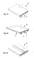
- the V-ribbed belt 13 a plurality of longitudinally arranged in parallel wedge-shaped grooves 5 and V-ribs 6 on.
- This wedge-shaped Grooves 5 and V-ribs 6 allow by their Wedge effect a rope force ratio of more than 2 at one Wrap angle of 180 degrees.
- V-ribbed belt 13 it is another advantage of the V-ribbed belt 13 that he himself on the driving or leading pulleys self centered.
- the V-ribbed belt 13 on the back i.e., on the side that is not wedge-shaped Grooves 5 or V-ribs 6) with a guide rib 2, as shown in FIG.
- This leadership rib 2 has the task, in a counter-bending of the V-ribbed belt, d. H. if this is a pulley with against the pulley straightened belt backside reveals the V-ribbed belt in a guide groove provided in the tread of the pulley respectively.
- the wedge-shaped grooves 5 of the V-ribbed belt 13 a Groove angle b of 80 degrees to 100 degrees.
- the groove angle b is about 90 degrees.
- This groove angle b is much larger than conventional V-ribbed belts. Achieved by the larger groove angle b a reduction of the running noise.
- the self-centering Property as well as one (defined above) increased rope power ratio remain but.
- the V-ribbed belt is 13 on the back, as shown in Fig. 13, with a Layer 4 provided, preferably good sliding properties Has.
- This layer 4 may be, for example, a fabric layer be. Facilitated in multi-suspended elevator systems this is the assembly.
- V-ribbed belt 13 is shown in FIG.
- This V-ribbed belt has both wedge-shaped grooves 5 and Ribs 6, which are applied in the longitudinal direction, as well Transverse grooves 3. These transverse grooves 3 improve bending flexibility of the V-ribbed belt, so this with Collaborate belt pulleys with reduced diameter can.
- the transmission means (V-ribbed belt 13) contains tension members 1 oriented in the longitudinal direction, which consist of metallic strands (eg steel strands) or non-metallic strands (eg of manmade fibers) , Such tension members 1 impart the required tensile strength and / or longitudinal rigidity to the transfer means according to the invention.
- a preferred embodiment of the transmission means comprises tension members 1 made of Zylon fibers.
- Zylon is a trade name of Toyobo Co. Ltd., Japan, and refers to manmade fibers of poly (p-phenylene-2,6-benzobisoxazole) (PBO).
- the tension members 1 should be in the V-ribbed belt be embedded in that adjacent fibers or strands do not touch.
- the ideal is a degree of filling, d. H. a ratio between the total cross section of all tension members and the cross-section of the belt, of at least 20% proved.
- FIG. 16 shows an embodiment of the V-ribbed belt 13 which is likewise suitable as transmission means for elevator systems.
- a flat tension layer 51 forms the core of the V-ribbed belt 13. This tension layer 51 extends substantially over the entire belt length and the entire belt width.
- the tension layer 51 can consist of an unreinforced material layer, for example of a polyamide film, or be formed of a film reinforced with synthetic fibers. Such a reinforced film could, for example, contain the aforementioned Zylon fibers embedded in a suitable plastic matrix.
- the tension layer 51 gives the flat belt the required tensile and creep resistance, but is also sufficiently flexible to withstand a sufficiently high number of bending operations when deflecting around a belt pulley.
- the V-ribbed layer 53 can be made, for example, of polyurethane or of an NBR elastomer (nitrile butadiene rubber) and is connected over the whole or part of the surface, directly or via an intermediate layer, to the tension layer 51.
- the rear side of the V-ribbed belt has a cover layer 54 connected to the tension layer 51 like the V-ribbed layer, which is advantageously designed as a sliding covering. Intermediate layers (not shown) may be present between said major layers to provide the necessary adhesion between said layers and / or increase the flexibility of the transfer medium.
- This V-ribbed belt provided with a full-area tension layer can also have a guide rib as already described in connection with FIG. 15.
- FIG. 17 another applicable in elevator systems Transfer means shown, which is to solve the inventive task is. It is about one of several layers of different materials constructed flat belt 50.
- the flat belt contains in the core at least one flat tensile layer 51, for example consists of an unreinforced polyamide film, or from a plastic film that is in the plastic matrix reinforced chemical fibers is reinforced.
- This train layer 51 gives the flat belt the required tension and Creep resistance, but is also flexible enough to one sufficiently high number of bending operations when redirecting to be able to endure a belt pulley.
- the flat belt 50 also has an outer, front-side friction layer 55, for example, from an NBR elastomer (nitriles butadienes Rubber), as well as an outer, back cover layer 54, which, depending on the elevator system, as a friction or sliding coating is executed. Between the mentioned main layers For example, intermediate layers 56 may be present which have the required To convey adhesion between the mentioned layers and / or increase the flexibility of the flat belt. For the purpose of Optimization of the aforementioned rope force ratio are Friction layers with coefficients of friction of 0.5 to 0.7 compared Steel pulleys available, which are also very resistant to abrasion.
- the lateral guidance of the flat belt 50 is usually, as shown in Fig. 18, by at the pulleys 16th attached flanges 57 ensures, possibly in Combined with a crowning of the pulley treads.
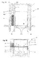
- FIGS. 1A and 1B A first embodiment of an elevator system 10 according to the invention is shown in FIGS. 1A and 1B.
- Fig. 1A shows a section through the head end of the elevator shaft 11.
- the elevator car 12 as well as a counterweight 15 are moved via a V-ribbed belt transmission means 13 within the shaft 11.
- a stationary drive 14 is provided which acts on the V-ribbed belt transmission means 13 via a drive pulley 16.1.
- the drive 14 is mounted on a bracket 9 which is supported on or on one or more guide rails 18 of the elevator system.
- the console 9 may be supported in or on the shaft wall.
- the V-ribbed belt transmission means 13 is fixed at its one end in the region of the bracket 9, leads from this fixed point down to a suspension pulley 16.2 of a counterweight 15, wraps around this suspension pulley 16.2, leads up to the Antriebspulley 16.1, wraps around this leads downwards a below the elevator car 12 attached to this first Umlenkpulley 16.3, from there horizontally below the elevator car 12 through to a second below the elevator car 12 attached to this Umlenkpulley 16.3 and then back up to a second, referred to as support structure 8 fixed point.
- the car 12 is moved up or down via the V-ribbed belt transmission means 13.
- the guide plane 20 formed by the two car guide rails 18 is, as shown in FIG.
- the car guide rails can be placed outside the space occupied by the V-ribbed belt transmission means 13 and the belt pulley, whereby on the one hand the axis of the strand of the V-ribbed belt transmission means 13 passing under the elevator car 12 can be arranged below the car's center of gravity S. when it lies in the guide plane 20 formed by the car guide rails 18.
- the claimed shaft width is minimized.
- the suspension pulley 16.2 and the underneath the elevator car 12 mounted Umlenkpulleys 16.3 results in a ratio of V-ribbed belt speed to cabin and counterweight speed of 2: 1 (2: 1 suspension). This is compared to a 1: 1 suspension the torque applied by the drive 14 half reduced.
- FIG Fig. 2 A cross-section through a similar embodiment is shown in FIG Fig. 2 shown.
- the elevator car 12 is accessed via a V-ribbed belt transmission means 13 within the shaft 11th emotional.
- a stationary drive 14 provided, the V-ribbed belt transmission means 13th drives.
- the drive 14 stationary above the upper end position of the counterweight 15 appropriate.
- the drive 14 is mounted on a bracket 9, on or on one or more guide rails 18 of the Elevator system 10 is supported.
- the bottom block 17 is perpendicular to the side walls the elevator shaft 11 in the plane of the drawing.
- this second embodiment is substantially similar the first embodiment.
- the car guide rails 18 are arranged eccentrically, i. the management level 20 is located between the car door 7 and the center of gravity S of the elevator car 12, which in the case shown on the Central axis of the V-ribbed belt transmission 13th lies.
- Fig. 3 shows a cross section through a further embodiment an elevator system 10.
- the drive 14 is on the counterweight rails 19 and on one of the car rails 18 supported.
- On the opposite side is the Fixed point of the V-ribbed belt transmission means 13 on the supported second cabin rail 18.
- the diagonal course of the V-ribbed belt transmission means 13 allows one in terms of the Cabin center point S centric guided and centric Suspended cabin 12 with the in connection with FIG described advantages.
- FIG. 14 In another embodiment, shown in FIG is the drive 14 on the two counterweight rails 19 and supported on an elevator rail 18. On the opposite side is the benchmark for here too fixing ends of the V-ribbed belt transmission means 13 supported on the second car rail 18.
- the drive 14 is in communication with two drive pulleys 16.1. It are two strands of V-ribbed belt transmission means Provided 13.1 and 13.2, which are parallel to each other. Also in this embodiment, cabin 12 and counterweight 15 hung 2: 1.
- the division of the V-ribbed belt transmission means into two parallel strands 13.1 and 13.2 allows a centric leadership and a in Concerning the cabin center of gravity S centric suspension of Elevator car 12 with those described in connection with FIG Benefits.
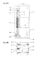
- FIGS. 5A and 5B A different arrangement 10 is shown in FIGS. 5A and 5B shown.
- the drive 14 is outside the cabin projection arranged above the upper end position of the counterweight 15.
- the drive can, as with the previous ones Embodiments, a synchronous or an asynchronous motor contain.
- the drive 14 is on a Carrier placed on or on the guide rails 18 the car 12 and the guides 19 to the counterweight 15 rests.
- the V-ribbed belt transmission means 13 is half to the left and right of the elevator car 12th arranged.
- the first half 13.1 of the V-ribbed belt transmission means 13 leads from the counterweight 15 over the Antriebspulley 16.2 to one on the elevator car 12 in the Near the ground existing fixed point.
- the second half 13.2 of the V-ribbed belt transmission means 13 leads from Counterweight 15 via the Antriebspulley 16.1 along the Schachtdecke 21 over the cabin 12. There it is from a Umlenkpulley 16.4 deflected and a second at the Elevator cabin 12 near the ground existing fixed point guided.
- the two guide rails 18 are at the top End preferably joined together (e.g. Cross member 24) to the horizontally directed belt force catch.
- the V-ribbed belt transmission means 13 and the guiding plane 20 of the elevator car 12 is symmetrical to the axis with the cabin center of gravity S arranged. you Distance to this axis is small to the executives, on the one hand in normal operation, on the other hand when intervening a safety gear to keep low.
- FIG. 5C Part of a machine room-less elevator system according to Figs. 5A and 5B.
- the drive 14 includes a motor 40, by a shaft 45 with the Antriebspulley 16.1 connected is.
- the drive 14 shown is very compact.
- the drive 14 is above the elevator shaft door 7 between the shaft inner wall 21 and the shaft outer wall 22 arranged. This is easily possible because of Diameter of the drive 14 is smaller than the shaft wall thickness D.
- the drive 14 may as in the other embodiments designed as a synchronous or asynchronous motor be.
- the drive is a small mass system, d. H. a drive with a low mass moment of inertia, used.
- the drive 14 is at the two ends depending provided with a Antechnischspulley 16.1. Both the Antriebspulleys 16.1 and the drive 14 can on be attached to a common support 43.
- the system 10 is equipped with two counterweights 15, each depending on one side of the elevator car 12 are arranged.
- the V-ribbed belt transmission means 13 are symmetrical the left and right sides of the elevator car 12 are arranged.
- First runs of the V-ribbed belt transmission means 13 lead from the Antriebspulleys 16.1 to first on same height fixed deflection pulley 16.5, of these from down to both sides attached to the elevator car 12 Umlenkpulley 16.6, wrap around this and lead up to fixed points 25.1.
- Second runs of V-ribbed belt transfer means 13 lead from the drive pulleys 16.1 out to the second fixed at the same height Umlenkpulley 16.7, from these downwards to the Counterweights 15 attached deflection pulley 16.8, loop around these and lead up to fixed points 25.2.
- the carriers 44 may communicate with the support 43 of the drive 14 form a U-shaped support structure. Horizontal and vertically acting forces are thus not on the shaft structure transfer.
- the car guide rails 18 and the Umlenkpulleys 16.6 attached to the elevator car 12 are in the direction of the cabin depth as close as possible to Cabin center S arranged to allow managers in the Normal operation as well as catching low remain.
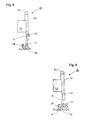
- FIG. 6C Details of a first drive 14 are shown in FIG. 6C. the component of a machine room-less elevator system according to FIGS. 6A and 6B.
- the drive 14 includes a Engine 40 and one or two brakes 41.
- the two Antriebspulleys 16.1 are by support members 44 with the Support 43 connected.
- Insulated torque arms 42 are used the attachment of the motor 40 to the support 43.
- the shaft 45 is executed throughout.
- the drive shown has low rotating masses and is due to its low Size suitable for installation in the shaft wall.
- FIG. 6D Details of a second drive 14 are shown in FIG. 6D. the component of a machine room-less elevator system according to FIGS. 6A and 6B.
- the drive 14 shown has a split shaft 46, the two coupling elements 47 is provided. Otherwise, this drive corresponds to the in Fig. 6C shown drive.
- the maintenance of the drive 14 can take place from the shaft interior.
- FIGS. 6A and Fig. 6B A development of the embodiment according to FIGS. 6A and Fig. 6B is shown in Figs. 7A and 7B.
- the embodiment differs in that two separate drives 14.1 and 14.2 are provided.
- the cabin 12 and the Counterweights 15 are suspended 2: 1.
- the side view in Figure 7B shows the always same direction bending of the V-ribbed belt transmission means 13, what's more premature Abrasion counteracts.
- Fig. 8 shows a first such embodiment.
- the cabin 12 and the counterweight 15 are with support means 33 in the form of ropes (e.g., steel ropes, aramid ropes), flat belts, Timing belt or chains connected together.
- a deflection pulley 31 is provided at the shaft head and can on the Guide rails (not shown) to be supported.
- Of the Drive 14 is located at the shaft bottom 32.
- V-ribbed belt drive means 13 the drive 14 moves the Cab 12.
- the V-ribbed belt driving means 13 is at a End connected to the lower side of the counterweight 15.
- the necessary clamping force can, for example, by means of a Compression spring 34, or by a corresponding counterweight be generated.
- the embodiment 30 shown in FIG. 9 corresponds to FIG Essentially the embodiment shown in Fig. 8.
- One Difference is that the drive 14 via a Reduction 35 features. This can be a smaller drive 14th be used.
- the drive 14 can via a V-belt or the like may be coupled to the reduction 35.
- FIGS. 10A and 10B show another embodiment of the invention Invention shown.
- the counterweight 15 is 1: 1 over one Supporting means 33 and several Umlenkpulleys 31 with the elevator car 12 connected.
- the support means 33 can either only on the left of the elevator car 12 (as shown) or on both sides the elevator car 12 (in dashed line) attached be. These compounds fulfill a purely load-bearing Function.
- the drive 14 is located above the counterweight 15 and is of a preferably on the guide rails 18, 19 fastened support 37 worn.
- the Counterweight 15 equals 100% of the cabin weight and one Part of the payload off.
- a V-ribbed belt 13 is at the top of Counterweight 15 directly attached (suspension 1: 1), over the Antriebspulley 16.1 deflected by 180 degrees and to the am Manhole bottom 32 located tension roller 38 out.
- the Tension pulley 38 redirects the V-ribbed belt 13 180 again Degree at which it moves up to the lower end of the Counterweight 15 out and attached there.
- the Tensioning roller 38 may be incorporated in a lever mechanism 39, the by means of spring or weight force the V-ribbed belt 13th stressed.
- FIGS. 10A and 10B can be considered modify, for example, by the V-ribbed belt 13th by suitable arrangement of pulleys leads to a so-called 2: 1 - Umhlindung forms, over which the drive 14 counterweight 15 drives (as in connection with Fig. 1A described). This allows the required maximum torque of the drive be halved.
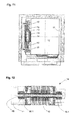
- FIG. Of the Drive 14 is located in the example shown between the elevator car 12 and the wall of the shaft 11.
- the Elevator car 12 and the counterweight 15 are on common Guide rails 18 out.
- these rails have a special profile. It can either Drive pulleys 16.1 on both sides of the drive 14 or be provided only on one side of the drive 14.
- Figure 12 shows a 1: 1 suspension.
- An execution with 2: 1 - suspension is possible if the V-ribbed belt 13, as shown for example in Fig. 1, below the elevator car 12 passed and on the other Cabin side be fixed in the shaft head.
- FIG. 1 Another compact drive 14 is shown in FIG. This drive 14 is characterized in that it has two Drive pulleys 16.1 has.
- the drive 14 comprises a motor 40, a brake 41 and a continuous Shaft 45.
- the two drive pulleys 16.1 each sit on one end of the shaft 45.
- the drive 14 is especially for the laterally above the cabin 12 lying installation designed.
- V-ribbed belt Teeth on, which are highly wear-resistant.
- the stationary drive is either in housed in a machine room, or the drive is located in or on the hoistway.
Landscapes
- Engineering & Computer Science (AREA)
- Civil Engineering (AREA)
- Mechanical Engineering (AREA)
- Structural Engineering (AREA)
- Lift-Guide Devices, And Elevator Ropes And Cables (AREA)
- Cage And Drive Apparatuses For Elevators (AREA)
- Devices For Conveying Motion By Means Of Endless Flexible Members (AREA)
- Paper (AREA)
- Vehicle Body Suspensions (AREA)
- Lubricants (AREA)
- Types And Forms Of Lifts (AREA)
- Adhesives Or Adhesive Processes (AREA)
- Compositions Of Macromolecular Compounds (AREA)
- Structure Of Belt Conveyors (AREA)
- Fluid-Pressure Circuits (AREA)
- Intermediate Stations On Conveyors (AREA)
- Polysaccharides And Polysaccharide Derivatives (AREA)
- Organic Low-Molecular-Weight Compounds And Preparation Thereof (AREA)
- Coating Apparatus (AREA)
- Input Circuits Of Receivers And Coupling Of Receivers And Audio Equipment (AREA)
- Pinball Game Machines (AREA)
Abstract
Description
- Fig. 1A
- ein erstes Aufzugssystem gemäss Erfindung, in stark vereinfachter und schematisierter Schnittdarstellung, mit einem Keilrippen-Riemen als Übertragungsmittel.
- Fig. 1B
- das erste Aufzugssystem, in stark vereinfachter und schematisierter Draufsicht, mit einem Keilrippen-Riemen als Übertragungsmittel.
- Fig. 2
- ein zweites Aufzugssystem, in stark vereinfachter und schematisierter Draufsicht, mit einem Keilrippen-Riemen als Übertragungsmittel.
- Fig. 3
- ein drittes Aufzugssystem, in stark vereinfachter und schematisierter Draufsicht, mit einem Keilrippen-Riemen als Übertragungsmittel.
- Fig. 4
- ein viertes Aufzugssystem, in stark vereinfachter und schematisierter Draufsicht, mit zwei Keilrippen-Riemen als Übertragungsmittel.
- Fig. 5A
- ein fünftes Aufzugssystem gemäss Erfindung, in stark vereinfachter und schematisierter Schnittdarstellung, mit einem Keilrippen-Riemen als Übertragungsmittel.
- Fig. 5B
- das fünfte Aufzugssystem, in stark vereinfachter und schematisierter Draufsicht, mit einem Keilrippen-Riemen als Übertragungsmittel.
- Fig. 5C
- einen Motor, in stark vereinfachter und schematisierter Darstellung, der als Antrieb für das fünfte Aufzugssystem geeignet ist.
- Fig. 6A
- ein sechstes Aufzugssystem gemäss Erfindung, in stark vereinfachter und schematisierter Draufsicht, mit zwei Keilrippen-Riemen als Übertragungsmittel.
- Fig. 6B
- das sechste Aufzugssystem, in stark vereinfachter und schematisierter Schnittdarstellung, mit zwei Keilrippen-Riemen als Übertragungsmittel.
- Fig. 6C
- einen ersten Motor, in stark vereinfachter und schematisierter Darstellung, der als Antrieb für das sechste Aufzugssystem geeignet ist.
- Fig. 6D
- einen zweiten Motor, in stark vereinfachter und schematisierter Darstellung, der als Antrieb für das sechste Aufzugssystem geeignet ist.
- Fig. 7A
- ein siebtes Aufzugssystem gemäss Erfindung, in stark vereinfachter und schematisierter Draufsicht, mit zwei Keilrippen-Riemen als Übertragungsmittel.
- Fig. 7B
- das siebte Aufzugssystem, in stark vereinfachter und schematisierter Schnittdarstellung, mit zwei Keilrippen-Riemen als Übertragungsmittel.
- Fig. 8
- ein achtes Aufzugssystem gemäss Erfindung, in stark vereinfachter und schematisierter Schnittdarstellung, mit einem Keilrippen-Riemen als Treibmittel und einem getrennten Tragmittel.
- Fig. 9
- ein neuntes Aufzugssystem gemäss Erfindung, in stark vereinfachter und schematisierter Schnittdarstellung, mit einem Keilrippen-Riemen als Treibmittel und einem getrennten Tragmittel.
- Fig. 10A
- ein zehntes Aufzugssystem gemäss Erfindung, in stark vereinfachter und schematisierter Schnittdarstellung, mit zwei Keilrippen-Riemen als Übertragungsmittel.
- Fig. 10B
- das zehnte Aufzugssystem, in stark vereinfachter und schematisierter Draufsicht, mit zwei Keilrippen-Riemen als Übertragungsmittel.
- Fig. 11
- ein elftes Aufzugssystem, in stark vereinfachter und schematisierter Draufsicht.
- Fig. 12
- einen weiteren Motor, in stark vereinfachter und schematisierter Darstellung, der als Antrieb für verschiedene Aufzugssystem gemäss Erfindung geeignet ist.
- Fig. 13
- ein erfindungsgemässes Übertragungsmittel in Form eines Keilrippen-Riemens.
- Fig. 14
- einen weiteren Keilrippen-Riemen, gemäss Erfindung.
- Fig. 15
- einen weiteren Keilrippen-Riemen, gemäss Erfindung.
- Fig. 16
- einen weiteren erfindungsgemässen KeilrippenRiemen mit Zugschicht.
- Fig. 17
- ein erfindungsgemässes Übertragungsmittel in Form eines Flachriemens.
- Fig. 18
- ein Riemenpulley mit Bordscheiben.
Eine bevorzugte Ausführungsform der Übertragungsmittel enthält Zugträger 1 aus Zylonfasern. Zylon ist ein Handelsname der Firma Toyobo Co. Ltd., Japan, und betrifft Chemiefasern aus Poly(p-phenylene-2,6-benzobisoxazole) (PBO). Diese Fasern übertreffen in den für die erfindungsgemässe Anwendung entscheidenden Eigenschaften diejenigen von Stahllitzen und von anderen bekannten Fasern. Die Längsdehnung und das Metergewicht des Übertragungsmittels können durch die Verwendung von Zylon-Fasern reduziert werden, wobei die Bruchkraft gleichzeitig höher ausfällt.
Die Zugschicht 51 verleiht dem Flachriemen die erforderliche Zug- und Kriechfestigkeit, ist aber auch genügend flexibel, um eine ausreichend hohe Zahl von Biegevorgängen beim Umlenken um ein Riemenpulley ertragen zu können.
Die Keilrippen-Schicht 53 kann beispielsweise aus Polyurethan oder aus einem NBR-Elastomer (Nitrile Butadiene Rubber) bestehen und ist ganz- oder teilflächig, direkt oder über eine Zwischenschicht mit der Zugschicht 51 verbunden. Die Rückseite des Keilrippen-Riemens weist eine wie die Keilrippen-Schicht mit der Zugschicht 51 verbundene Deckschicht 54 auf, die vorteilhafterweise als Gleitbelag ausgeführt ist. Zwischen den genannten Haupt-Schichten können Zwischenschichten (hier nicht dargestellt) vorhanden sein, die die erforderliche Haftung zwischen den genannten Schichten vermitteln und/oder die Flexibilität des Übertragungsmittels erhöhen. Dieser mit einer ganzflächigen Zugschicht versehene Keilrippen-Riemen kann auch eine wie bereits im Zusammenhang mit Fig. 15 beschriebene Führungsrippe aufweisen.
Die durch die beiden Kabinenführungsschienen 18 gebildete Führungsebene 20 ist, wie in Fig. 1B gezeigt, gegenüber dem unter der Aufzugkabine 12 hindurchführenden Strang des Keilrippen-Riemen-Übertragungsmittel 13, d. h. gegenüber der Querachse der Aufzugkabine 12, um einem Winkel a von 15 bis 20 Grad verdreht angeordnet. Dadurch können die Kabinenführungsschienen ausserhalb des vom Keilrippen-Riemen-Übertragungsmittel 13 und den Riemenpulleys beanspruchten Raums platziert werden, wodurch erreicht wird, dass einerseits die Achse des unter der Aufzugkabine 12 hindurchführenden Strangs des Keilrippen-Riemen-Übertragungsmittel 13 unterhalb des Kabinenschwerpunkts S angeordnet werden kann, wenn dieser in der durch die Kabinenführungsschienen 18 gebildete Führungsebene 20 liegt. Ausserdem wird damit die beanspruchte Schachtbreite minimiert.
Claims (9)
- Aufzugssystem (10) mit einem Antrieb (14), der über mindestens zwei parallel angeordnete Übertragungsmittel (13.1, 13.2) mit einer Aufzugkabine (12) und einem Gegengewicht (15) zusammenwirkt, um die Aufzugkabine (12) und das Gegengewicht (15) durch Übertragung einer Kraft zu bewegen, wobei die Aufzugskabine (12) an vertikalen Kabinenführungsschienen (18) geführt ist,
dadurch gekennzeichnet, dass an der Aufzugskabine (12) eine Gruppe von entlang einer gemeinsamen Achse angeordneten, mit den Übertragungsmitteln (13.1, 13.2) zusammenwirkenden Umlenkpulleys (16.3) angebracht ist und eine Kabinenführungsschiene (18) in einen zwischen zwei Umlenkpulleys (16.3) liegenden Zwischenraum hineinragt. - Aufzugssystem nach Anspruch 1, dadurch gekennzeichnet, dass die Umlenkpulleys (16.3) unterhalb der Aufzugskabine (12) an dieser angebracht sind und die Übertragungsmittel (13.1, 13.2) unter der Aufzugskabine hindurchführen.
- Aufzugssystem nach Anspruch 2, dadurch gekennzeichnet, dass mindestens zwei entlang einer gemeinsamen Achse angeordnete Umlenkpulleys (16.3) um eine gewisse Distanz über eine einer Kabinenführungsschiene (18) benachbarte Seitenwand der Aufzugskabine (12) hinausragen, wobei die gemeinsame Achse parallel zur genannten Seitenwand verläuft und zwischen zwei der Umlenkpulleys (16.3) ein Zwischenraum vorhanden ist.
- Aufzugssystem nach Anspruch 3, dadurch gekennzeichnet, dass die Kabinenführungsschiene (18) vertikal und parallel zur benachbarten Kabinenwand im Bereich des Zwischenraums zwischen zwei Umlenkpulleys (16.3) angeordnet ist, wobei der Abstand der Kabinenführungsschiene (18) zur Kabinenwand geringer ist, als die Distanz, um welche die Umlenkpulleys (16.3) über die Kabinenwand hinausragen.
- Aufzugssystem nach Anspruch 4, dadurch gekennzeichnet, dass auf zwei Seiten der Aufzugskabine (12) eine Kabinenführungsschiene (18) in den zwischen zwei Umlenkpulleys (16.3) vorhandenen Zwischenraum hineinragt.
- Aufzugssystem nach einem der Ansprüche 1 - 5, dadurch gekennzeichnet, dass die Übertragungsmittel (13.1, 13.2) riemenartige Übertragungsmittel sind.
- Aufzugssystem nach Anspruch 6, dadurch gekennzeichnet, dass die Übertragungsmittel (13.1, 13.2) Keilrippenriemen sind.
- Aufzugssystem nach Anspruch 7, dadurch gekennzeichnet, dass die Keilrippenriemen keilförmige Längsrippen (5) und Längsrillen (6) aufweisen, wobei ein zwischen zwei benachbarten Flanken einer Längsrippe (5) oder Längsrille (6) vorhandener Rillenwinkel (b) zwischen 80° und 100° liegt.
- Aufzugssystem nach einem der Ansprüche 1 - 8, dadurch gekennzeichnet, dass der Antrieb (14) auf einer Kabinenführungsschiene (18) abgestützt ist, welche in den zwischen zwei Umlenkpulleys (16.3) vorhandenen Zwischenraum hineinragt.
Priority Applications (2)
| Application Number | Priority Date | Filing Date | Title |
|---|---|---|---|
| EP05104453A EP1580156B1 (de) | 2001-11-23 | 2002-11-20 | Aufzug mit riemenartigem Übertragungsmittel, insbesondere mit Keilrippenriemen, als Tragmittel und/oder Treibmittel |
| ES05104453T ES2306013T3 (es) | 2001-11-23 | 2002-11-20 | Ascensor con medios de transmision del tipo correa, en particular correas trapeciales con dentado interior, como medio portante y/o agente motor. |
Applications Claiming Priority (4)
| Application Number | Priority Date | Filing Date | Title |
|---|---|---|---|
| EP01811132 | 2001-11-23 | ||
| EP01811132 | 2001-11-23 | ||
| EP02774244A EP1446348B1 (de) | 2001-11-23 | 2002-11-20 | Aufzug mit riemenartigem übertragungsmittel, insbesondere mit keilrippen-riemen, als tragmittel und/oder treibmittel |
| EP05104453A EP1580156B1 (de) | 2001-11-23 | 2002-11-20 | Aufzug mit riemenartigem Übertragungsmittel, insbesondere mit Keilrippenriemen, als Tragmittel und/oder Treibmittel |
Related Parent Applications (2)
| Application Number | Title | Priority Date | Filing Date |
|---|---|---|---|
| EP02774244A Division EP1446348B1 (de) | 2001-11-23 | 2002-11-20 | Aufzug mit riemenartigem übertragungsmittel, insbesondere mit keilrippen-riemen, als tragmittel und/oder treibmittel |
| EP02774244.4 Division | 2002-11-20 |
Publications (2)
| Publication Number | Publication Date |
|---|---|
| EP1580156A1 true EP1580156A1 (de) | 2005-09-28 |
| EP1580156B1 EP1580156B1 (de) | 2008-04-30 |
Family
ID=8184263
Family Applications (9)
| Application Number | Title | Priority Date | Filing Date |
|---|---|---|---|
| EP05103258A Revoked EP1561720B1 (de) | 2001-11-23 | 2002-11-20 | Aufzug mit riemenartigem Übertragungsmittel, insbesondere mit Keilrippen-Riemen, als Tragmittel und/oder Treibmittel |
| EP02774244A Expired - Lifetime EP1446348B1 (de) | 2001-11-23 | 2002-11-20 | Aufzug mit riemenartigem übertragungsmittel, insbesondere mit keilrippen-riemen, als tragmittel und/oder treibmittel |
| EP07108982A Revoked EP1834919B1 (de) | 2001-11-23 | 2002-11-20 | Aufzugssystem |
| EP05006057A Expired - Lifetime EP1547960B1 (de) | 2001-11-23 | 2002-11-20 | Aufzug mit riemenartigem Übertragungsmittel, insbesondere mit Keilrippen-Riemen, als Tragmittel und/oder Treibmittel |
| EP05104453A Revoked EP1580156B1 (de) | 2001-11-23 | 2002-11-20 | Aufzug mit riemenartigem Übertragungsmittel, insbesondere mit Keilrippenriemen, als Tragmittel und/oder Treibmittel |
| EP05106721A Expired - Lifetime EP1604939B1 (de) | 2001-11-23 | 2002-11-20 | Aufzug mit riemenartigem Übertragungsmittel, insbesondere mit Keilrippen-Riemen, als Tragmittel und/oder Treibmittel |
| EP02776635A Expired - Lifetime EP1446352B1 (de) | 2001-11-23 | 2002-11-22 | Aufzugssystem |
| EP02776633A Expired - Lifetime EP1446350B1 (de) | 2001-11-23 | 2002-11-22 | Aufzugssystem |
| EP02776634A Expired - Lifetime EP1446351B1 (de) | 2001-11-23 | 2002-11-22 | Aufzugssystem |
Family Applications Before (4)
| Application Number | Title | Priority Date | Filing Date |
|---|---|---|---|
| EP05103258A Revoked EP1561720B1 (de) | 2001-11-23 | 2002-11-20 | Aufzug mit riemenartigem Übertragungsmittel, insbesondere mit Keilrippen-Riemen, als Tragmittel und/oder Treibmittel |
| EP02774244A Expired - Lifetime EP1446348B1 (de) | 2001-11-23 | 2002-11-20 | Aufzug mit riemenartigem übertragungsmittel, insbesondere mit keilrippen-riemen, als tragmittel und/oder treibmittel |
| EP07108982A Revoked EP1834919B1 (de) | 2001-11-23 | 2002-11-20 | Aufzugssystem |
| EP05006057A Expired - Lifetime EP1547960B1 (de) | 2001-11-23 | 2002-11-20 | Aufzug mit riemenartigem Übertragungsmittel, insbesondere mit Keilrippen-Riemen, als Tragmittel und/oder Treibmittel |
Family Applications After (4)
| Application Number | Title | Priority Date | Filing Date |
|---|---|---|---|
| EP05106721A Expired - Lifetime EP1604939B1 (de) | 2001-11-23 | 2002-11-20 | Aufzug mit riemenartigem Übertragungsmittel, insbesondere mit Keilrippen-Riemen, als Tragmittel und/oder Treibmittel |
| EP02776635A Expired - Lifetime EP1446352B1 (de) | 2001-11-23 | 2002-11-22 | Aufzugssystem |
| EP02776633A Expired - Lifetime EP1446350B1 (de) | 2001-11-23 | 2002-11-22 | Aufzugssystem |
| EP02776634A Expired - Lifetime EP1446351B1 (de) | 2001-11-23 | 2002-11-22 | Aufzugssystem |
Country Status (18)
| Country | Link |
|---|---|
| US (5) | US7367430B2 (de) |
| EP (9) | EP1561720B1 (de) |
| JP (5) | JP2005509578A (de) |
| CN (5) | CN101062742A (de) |
| AT (9) | ATE382578T1 (de) |
| AU (6) | AU2002340704B2 (de) |
| BR (5) | BR0216031B1 (de) |
| CA (4) | CA2465031C (de) |
| CY (1) | CY1105599T1 (de) |
| DE (8) | DE50211490D1 (de) |
| DK (6) | DK1446348T3 (de) |
| ES (9) | ES2306013T3 (de) |
| MX (3) | MXPA04004787A (de) |
| NO (4) | NO330310B1 (de) |
| NZ (1) | NZ532893A (de) |
| PT (4) | PT1561720E (de) |
| WO (4) | WO2003043922A1 (de) |
| ZA (3) | ZA200403135B (de) |
Families Citing this family (113)
| Publication number | Priority date | Publication date | Assignee | Title |
|---|---|---|---|---|
| DE50211490D1 (de) * | 2001-11-23 | 2008-02-14 | Inventio Ag | Aufzug mit riemenartigem Übertragungsmittel, insbesondere mit Keilrippen-Riemen, als Tragmittel und/oder Treibmittel |
| US20030121729A1 (en) * | 2002-01-02 | 2003-07-03 | Guenther Heinz | Lift belt and system |
| DE10240988B4 (de) * | 2002-09-05 | 2014-02-27 | Inventio Ag | Aufzugsanlage mit einer aus Riemen und Scheiben bestehenden Antriebsübertragungsanordnung |
| US7377366B2 (en) * | 2002-11-25 | 2008-05-27 | Otis Elevator Company | Sheave assembly for an elevator system |
| JP4657612B2 (ja) * | 2003-03-06 | 2011-03-23 | インベンテイオ・アクテイエンゲゼルシヤフト | エレベータ |
| JP2004352377A (ja) * | 2003-05-27 | 2004-12-16 | Otis Elevator Co | エレベータ |
| DE60336087D1 (de) * | 2003-06-12 | 2011-03-31 | Otis Elevator Co | Maschinenraumlose aufzugskonfiguration mit kleinem schachtkopf |
| JP2005008414A (ja) * | 2003-06-18 | 2005-01-13 | Inventio Ag | エレベーター設備、このエレベーター設備を操作する方法、およびエレベーター設備を最新化する方法 |
| JP2005139001A (ja) | 2003-11-04 | 2005-06-02 | Inventio Ag | 支持手段を点検する方法および装置 |
| FI119020B (fi) * | 2003-11-24 | 2008-06-30 | Kone Corp | Hissi ja menetelmä nostoköysistön hallitsemattoman löystymisen ja/tai tasauslaitteen hallitsemattoman liikkeen estämiseksi |
| ZA200409347B (en) | 2003-12-01 | 2005-07-27 | Inventio Ag | Lift system |
| JPWO2005056456A1 (ja) * | 2003-12-11 | 2007-07-05 | 三菱電機株式会社 | エレベータ装置 |
| DK1555234T3 (da) * | 2004-01-06 | 2006-08-21 | Inventio Ag | Elevator |
| ES2618326T3 (es) * | 2004-01-07 | 2017-06-21 | Inventio Ag | Procedimiento para modernizar un accionamiento en una instalación de ascensor |
| ES2353504T5 (es) | 2004-03-15 | 2018-04-30 | Otis Elevator Company | Método de fabricación de un miembro de soporte de carga de ascensor que tiene una envoltura con al menos una superficie exterior rugosa |
| ES2253981B1 (es) * | 2004-05-10 | 2007-06-16 | Orona, S. Coop. | Cable y cinta para limitador de velocidad de ascensores y poleas asociadas. |
| NZ540310A (en) * | 2004-06-19 | 2006-03-31 | Inventio Ag | Drive for a lift installation |
| ATE417804T1 (de) * | 2004-09-13 | 2009-01-15 | Inventio Ag | Tragmittelendverbindung zur befestigung eines endes eines tragmittels in einer aufzugsanlage und verfahren zur befestigung eines endes eines tragmittels in einer aufzugsanlage |
| CN100528728C (zh) * | 2004-09-30 | 2009-08-19 | 三菱电机株式会社 | 电梯装置 |
| FI118383B (fi) * | 2004-11-16 | 2007-10-31 | Kone Corp | Hissin köysijärjestely |
| JP2006182566A (ja) * | 2004-12-24 | 2006-07-13 | Inventio Ag | ベルト状の駆動手段をもつ装置、およびその装置における電気エネルギーまたは信号を伝達する方法 |
| FR2881125B1 (fr) * | 2005-01-24 | 2008-11-07 | Serge Arnoult | Installation d'ascenseur a element lineaire unique d'entrainement de la cabine de passagers |
| EP1700809B1 (de) | 2005-03-12 | 2010-04-28 | ThyssenKrupp Elevator AG | Aufzuganlage |
| SG129351A1 (en) * | 2005-07-22 | 2007-02-26 | Inventio Ag | Lift installation with a support means end connection and a support means, and a method of fasteningan end of a support means in a lift installation |
| US7358314B2 (en) * | 2005-08-18 | 2008-04-15 | Alliant Techsystems Inc. | Polybenzoxazole-filled nitrile butadiene rubber compositions |
| DE602005015582D1 (de) * | 2005-09-06 | 2009-09-03 | Elex Italia S R L | Hebeeinrichtung ohne Maschinenraum für Personen und Gütern. |
| SG131070A1 (en) * | 2005-10-04 | 2007-04-26 | Inventio Ag | Method of mounting a support means of a lift cage to a lift cage and to a lift shaft |
| JP5627829B2 (ja) * | 2005-10-21 | 2014-11-19 | インベンテイオ・アクテイエンゲゼルシヤフトInventio Aktiengesellschaft | 駆動プーリと支持手段を備えた支持手段システム、およびこのような支持手段システムを備えたエレベータ設備 |
| US7882935B2 (en) | 2005-10-21 | 2011-02-08 | Inventio Ag | Support means system with drive pulley and support means as well as elevator installation with such a support means system |
| ITMI20062233A1 (it) * | 2006-11-22 | 2008-05-23 | Fata Fab App Sollevamento | Impianto di magazzino multipiano con celle elevatrici |
| JP2007246194A (ja) * | 2006-03-14 | 2007-09-27 | Toshiba Elevator Co Ltd | マシンルームレスエレベータ |
| KR100956208B1 (ko) * | 2006-04-19 | 2010-05-04 | 미쓰비시덴키 가부시키가이샤 | 엘리베이터 장치 |
| CN101074077A (zh) * | 2006-05-19 | 2007-11-21 | 沈阳博林特电梯有限公司 | 曳引驱动电梯系统 |
| ES2407981T3 (es) * | 2006-06-14 | 2013-06-17 | Inventio Ag | Ascensor |
| CN101472829A (zh) | 2006-06-26 | 2009-07-01 | 奥蒂斯电梯公司 | 减小井道尺寸的升降机安装 |
| RU2459762C2 (ru) * | 2006-06-26 | 2012-08-27 | Отис Элевейтэ Кампэни | Грузоподъемная система (варианты) |
| US20080073156A1 (en) * | 2006-08-11 | 2008-03-27 | Ernst Ach | Belt for an elevator installation, production method for such a belt and elevator installation with such a belt |
| NZ556752A (en) * | 2006-08-11 | 2009-03-31 | Inventio Ag | Lift installation with a lift support means, lift support means for such a lift installation and production method for such lift support means |
| EP1886957A1 (de) | 2006-08-11 | 2008-02-13 | Inventio Ag | Aufzugriemen für eine Aufzuganlage und Verfahren zur Herstellung eines solchen Aufzugriemens |
| DE502006006078D1 (de) * | 2006-08-11 | 2010-03-25 | Inventio Ag | Aufzugriemen für eine Aufzuganlage und Verfahren zur Herstellung eines solchen Aufzugriemens |
| JP2008069008A (ja) * | 2006-08-11 | 2008-03-27 | Inventio Ag | エレベータ装置のベルト、そのようなベルトの製造方法、およびそのようなベルトを備えるエレベータ装置 |
| SG139701A1 (en) * | 2006-08-11 | 2008-02-29 | Inventio Ag | Lift installation with a belt, belt for such a lift installation, method of producing such a belt, composite of such belts and method for assembly of such a composite in a lift installation |
| US20080067008A1 (en) * | 2006-08-11 | 2008-03-20 | Ernst Ach | Elevator installation with an elevator support means, elevator support means for such an elevator installation and production method for such elevator support means |
| JP4940823B2 (ja) * | 2006-08-18 | 2012-05-30 | フジテック株式会社 | エレベータ装置 |
| EP1894876A1 (de) * | 2006-08-31 | 2008-03-05 | Inventio Ag | Disposition einer Kabine und einem Gegengewicht in Aufzugsschacht |
| KR100795265B1 (ko) | 2006-09-20 | 2008-01-15 | 미쓰비시덴키 가부시키가이샤 | 엘리베이터 장치 |
| ES2294943B1 (es) * | 2006-09-25 | 2009-02-16 | Orona S. Coop | Aparato elevador sin sala de maquinas. |
| NZ562338A (en) * | 2006-10-31 | 2009-07-31 | Inventio Ag | Lift with two lift cages disposed one above the other in a lift shaft |
| MY149246A (en) * | 2006-12-22 | 2013-07-31 | Inventio Ag | Elevator installation in a building with at least one transfer floor |
| US7882934B2 (en) * | 2006-12-22 | 2011-02-08 | Inventio Ag | Elevator installation in a building with at least one transfer floor |
| US7913818B2 (en) * | 2006-12-22 | 2011-03-29 | Inventio Ag | Elevator installation in a building with at least one transfer floor |
| ZA200710589B (en) * | 2006-12-22 | 2008-11-26 | Inventio Ag | Lift installation in a building with at least one transfer storey |
| ITMI20062542A1 (it) * | 2006-12-29 | 2008-06-30 | L A Consulting S A S | Ascensore con doppia puleggia di trazione |
| DE202008001786U1 (de) | 2007-03-12 | 2008-12-24 | Inventio Ag | Aufzugsanlage, Tragmittel für eine Aufzugsanlage und Vorrichtung zur Herstellung eines Tragmittels |
| JP5400620B2 (ja) * | 2007-03-12 | 2014-01-29 | オーチス エレベータ カンパニー | エレベータシステム |
| EP1975111A1 (de) * | 2007-03-28 | 2008-10-01 | Inventio Ag | Aufzugriemen, Herstellungsverfahren für einen solchen Aufzugriemen und Aufzuganlage mit einem solchen Riemen |
| WO2008110241A2 (de) * | 2007-03-12 | 2008-09-18 | Inventio Ag | Aufzugsanlage, tragmittel für eine aufzugsanlage und verfahren zur herstellung eines tragmittels |
| CN101298307B (zh) | 2007-05-03 | 2010-06-23 | 因温特奥股份公司 | 电梯设备,电梯设备用转向辊,和设置负载传感器的方法 |
| DE102007021434B4 (de) * | 2007-05-08 | 2018-10-18 | Contitech Antriebssysteme Gmbh | Aufzugsanlagenzugmittel |
| WO2009011698A1 (en) * | 2007-07-18 | 2009-01-22 | Otis Elevator Company | Drive belt configuration for passenger conveyors |
| CN101456510B (zh) * | 2007-12-14 | 2010-09-15 | 上海三菱电梯有限公司 | 电梯装置 |
| US8479887B2 (en) * | 2008-08-15 | 2013-07-09 | Otis Elevator Company | Cord and polymer jacket assembly having a flame retardant in the polymer jacket material |
| WO2010052109A1 (de) * | 2008-11-05 | 2010-05-14 | Inventio Ag | Modernisierungsverfahren für aufzuganlagen |
| DE102008037538A1 (de) * | 2008-11-10 | 2010-05-12 | Contitech Antriebssysteme Gmbh | Traktionssystem für eine Aufzugsanlage |
| EP2210847A1 (de) * | 2009-01-22 | 2010-07-28 | Inventio AG | Aufzuganlage mit Treibscheibe |
| USD638445S1 (en) * | 2009-02-12 | 2011-05-24 | Contitech Antriebssysteme Gmbh | Drive belt |
| JP2010184791A (ja) * | 2009-02-13 | 2010-08-26 | Toshiba Elevator Co Ltd | エレベータ |
| US20120006626A1 (en) * | 2009-04-29 | 2012-01-12 | Otis Elevator Company | Elevator system including multiple cars within a single hoistway |
| DE102009044079A1 (de) | 2009-09-23 | 2011-03-24 | Contitech Antriebssysteme Gmbh | Elastischer Antriebsriemen in Form eines Keilriemens oder eines Keilrippenriemens mit einem vergrößerten Flankenwinkel |
| CN102574665B (zh) * | 2009-10-14 | 2015-11-25 | 因温特奥股份公司 | 升降机系统以及用于这种系统的承载构件 |
| WO2011073030A1 (de) * | 2009-12-15 | 2011-06-23 | Inventio Ag | Aufzuganlage mit doppeldecker |
| CN108046083B (zh) | 2010-04-22 | 2020-02-21 | 蒂森克虏伯电梯股份有限公司 | 升降机悬架和传输条带 |
| JP5688450B2 (ja) * | 2010-05-13 | 2015-03-25 | オーチス エレベータ カンパニーOtis Elevator Company | 張力部材の間に所望の離間距離を有する織物の製造方法 |
| US20120085594A1 (en) * | 2010-10-11 | 2012-04-12 | Tim Wright | Drive Arrangement for Machine Roomless Elevator |
| US8925689B2 (en) | 2011-01-19 | 2015-01-06 | Smart Lifts, Llc | System having a plurality of elevator cabs and counterweights that move independently in different sections of a hoistway |
| US8430210B2 (en) | 2011-01-19 | 2013-04-30 | Smart Lifts, Llc | System having multiple cabs in an elevator shaft |
| US9365392B2 (en) | 2011-01-19 | 2016-06-14 | Smart Lifts, Llc | System having multiple cabs in an elevator shaft and control method thereof |
| US9371212B2 (en) * | 2011-04-06 | 2016-06-21 | Otis Elevator Company | Elevator system including a 4:1 roping arrangement |
| FI124541B (fi) * | 2011-05-18 | 2014-10-15 | Kone Corp | Hissijärjestely |
| FI20115641A7 (fi) * | 2011-06-22 | 2012-12-23 | Kone Corp | Hissin vetoelimen kiristysjärjestely |
| US20130056305A1 (en) * | 2011-09-07 | 2013-03-07 | Jose Luis Blanco Sanchez | Elevator With Cogged Belt and Pulley and With Counterweight |
| FI125114B (fi) | 2011-09-15 | 2015-06-15 | Kone Corp | Hissin ripustus- ja ohjainjärjestely |
| FI20115920A0 (fi) * | 2011-09-19 | 2011-09-19 | Kone Corp | Hihnamaisella rakenteella toteutettu vetoelinjärjestely, hissi ja vetoelinjärjestelyn vetoelimien käyttö hississä |
| CN103974891B (zh) * | 2011-12-07 | 2016-08-17 | 三菱电机株式会社 | 电梯装置 |
| FI124486B (fi) * | 2012-01-24 | 2014-09-30 | Kone Corp | Nostolaitteen köysi, köysijärjestely, hissi ja nostolaitteen köyden kunnonvalvontamenetelmä |
| FI123534B (fi) * | 2012-02-13 | 2013-06-28 | Kone Corp | Nostolaitteen köysi, hissi ja menetelmä köyden valmistamiseksi |
| US10384289B2 (en) * | 2012-06-08 | 2019-08-20 | Illinois Tool Works Inc. | Welding wire feeder bus control system and method |
| US20150210511A1 (en) * | 2012-07-20 | 2015-07-30 | Inventio Ag | Elevator installation deflecting roller |
| EP2703330B1 (de) * | 2012-08-31 | 2015-08-26 | KONE Corporation | Aufzug |
| EP2712834A1 (de) * | 2012-09-27 | 2014-04-02 | Inventio AG | Antriebs- und Seilführungskonfiguration |
| WO2014063900A1 (en) | 2012-10-22 | 2014-05-01 | Nv Bekaert Sa | A belt for lifting |
| ES2624221T3 (es) * | 2013-02-14 | 2017-07-13 | Kone Corporation | Un ascensor |
| CN104860166B (zh) * | 2014-02-26 | 2017-09-29 | 上海三菱电梯有限公司 | 使用扁平拉伸组件作为悬挂装置的升降机系统 |
| DE102014012189A1 (de) | 2014-08-20 | 2016-02-25 | Arntz Beteiligungs Gmbh & Co. Kg | Kraftübertragungsriemen |
| EP3283425B1 (de) | 2015-04-17 | 2020-08-19 | Otis Elevator Company | Aufzugsystem |
| FI126915B (fi) * | 2015-10-20 | 2017-08-15 | Kone Corp | Hihnamainen vetoelin ja menetelmä vetoelimen valmistamiseksi sekä mainitun vetoelimen käyttö hississä ja mainitulla vetoelimellä varustettu hissi |
| EP3243785B1 (de) * | 2016-05-11 | 2021-04-07 | KONE Corporation | Seil, aufzugsanordnung und aufzug |
| CN106144838A (zh) * | 2016-06-30 | 2016-11-23 | 江南嘉捷电梯股份有限公司 | 一种电梯 |
| CN105947850A (zh) * | 2016-06-30 | 2016-09-21 | 江南嘉捷电梯股份有限公司 | 一种电梯曳引承载机构 |
| CN105923503A (zh) * | 2016-06-30 | 2016-09-07 | 江南嘉捷电梯股份有限公司 | 一种电梯曳引悬挂装置及电梯 |
| CN105923502B (zh) * | 2016-06-30 | 2019-09-03 | 苏州江南嘉捷电梯有限公司 | 一种电梯曳引悬挂系统 |
| US10894696B2 (en) | 2016-07-11 | 2021-01-19 | Otis Elevator Company | Belt with guide elements |
| CN106006322A (zh) * | 2016-07-12 | 2016-10-12 | 江南嘉捷电梯股份有限公司 | 一种电梯曳引构件 |
| CN106081793A (zh) * | 2016-07-12 | 2016-11-09 | 江南嘉捷电梯股份有限公司 | 一种电梯牵引系统 |
| US9994425B1 (en) | 2016-12-12 | 2018-06-12 | Thyssenkrupp Elevator Ag | Compact motor arrangement with integrated brakes and shaft bearings |
| US10562740B2 (en) | 2017-09-15 | 2020-02-18 | Otis Elevator Company | Elevator load bearing termination assembly for carbon fiber belt |
| ES2923401T3 (es) | 2017-10-17 | 2022-09-27 | Inventio Ag | Sistema elevador con elementos de desviación con diferentes geometrías de ranura |
| US11001474B2 (en) * | 2018-01-15 | 2021-05-11 | Otis Elevator Company | Wear detection of elevator belt |
| CN109052105A (zh) * | 2018-09-07 | 2018-12-21 | 苏州工业职业技术学院 | 一种无机房电梯布置结构 |
| EP3969401B1 (de) * | 2019-05-17 | 2025-07-02 | Inventio Ag | Aufzuglaufrolle für eine aufzuganlage, aufzuganlage mit zumindest einer solchen aufzuglaufrolle und verfahren zum herstellen einer aufzuglaufrolle |
| EP3771681B1 (de) * | 2019-08-02 | 2022-04-27 | Hans Lutz Maschinenfabrik GmbH & Co. KG | Aufzug mit elastisch gelagerter tragsäule |
| EP3816089B1 (de) * | 2019-10-31 | 2025-01-08 | KONE Corporation | Verfahren zum abseilen eines aufzugs |
| EP4273081A1 (de) * | 2022-05-05 | 2023-11-08 | Otis Elevator Company | Aufzugskabine mit elektronischem sicherheitsstellglied |
Citations (5)
| Publication number | Priority date | Publication date | Assignee | Title |
|---|---|---|---|---|
| US2728239A (en) * | 1953-08-12 | 1955-12-27 | Raybestos Manhattan Inc | Power transmission drive and belt therefor |
| DE1032496B (de) * | 1954-01-18 | 1958-06-19 | Joseph Tepper Maschinenfabrik | Aufzugsanlage fuer Treibscheibenantrieb |
| FR2275400A1 (fr) * | 1974-05-28 | 1976-01-16 | Kone Oy | Ascenseur ou monte-charge |
| EP0905081A2 (de) * | 1997-09-26 | 1999-03-31 | Kabushiki Kaisha Toshiba | Einsetzen einer Antriebseinheit in einem Aufzugsschacht |
| WO2000037738A1 (en) * | 1998-12-22 | 2000-06-29 | Otis Elevator Company | Tension member for an elevator |
Family Cites Families (76)
| Publication number | Priority date | Publication date | Assignee | Title |
|---|---|---|---|---|
| US1011423A (en) * | 1908-03-27 | 1911-12-12 | Otis Elevator Co | Belt-drive elevator. |
| US975790A (en) * | 1908-11-25 | 1910-11-15 | Charles O Pearson | Multiple metallic belt for traction-elevators. |
| US1035230A (en) * | 1911-10-24 | 1912-08-13 | Charles O Pearson | Traction-elevator. |
| US1729329A (en) * | 1927-04-13 | 1929-09-24 | Inland Mfg Co | Transmission belt |
| US1796875A (en) * | 1927-05-17 | 1931-03-17 | Felten & Guilleaume Carlswerk | Rope hoist |
| US2472513A (en) * | 1945-02-26 | 1949-06-07 | Bergquist Nils Olof | Belt driving device |
| US3174585A (en) * | 1962-08-13 | 1965-03-23 | Otis Elevator Co | Elevator hoisting mechanism |
| JPS4815497B1 (de) | 1968-03-04 | 1973-05-15 | ||
| US3643518A (en) * | 1970-06-08 | 1972-02-22 | Goodyear Tire & Rubber | Belt and belt drive assembly |
| US3756433A (en) * | 1971-04-06 | 1973-09-04 | Eaton Corp | Material handling system |
| DE2213424B1 (de) * | 1972-03-20 | 1973-07-26 | Treibriemen | |
| US3980174A (en) * | 1975-10-10 | 1976-09-14 | Dynaloc Corporation | Closed loop ribbed belt/grooved pulley conveyor system |
| JPS61148810A (ja) * | 1984-12-21 | 1986-07-07 | 宇部興産株式会社 | 強誘電体素子 |
| JPS62199553U (de) * | 1986-06-09 | 1987-12-18 | ||
| FR2624238B1 (fr) * | 1987-12-08 | 1990-05-04 | Hutchinson | Perfectionnements aux courroies de transmission de puissance |
| FI84051C (fi) * | 1988-03-09 | 1991-10-10 | Kone Oy | Linupphaengning foer en hiss. |
| JP2614747B2 (ja) * | 1988-06-10 | 1997-05-28 | 日本オーチス・エレベータ株式会社 | エレベータロープの制振装置 |
| US4904232A (en) * | 1988-10-31 | 1990-02-27 | Mitsuboshi Belting, Ltd. | Power transmission belt |
| US4981462A (en) * | 1989-02-21 | 1991-01-01 | Dayco Products, Inc. | Belt construction, rotatable pulley and combination thereof and methods making the same |
| US4900294A (en) * | 1989-04-11 | 1990-02-13 | Erich Gottfried Schneeberger | Garage door opener drive mechanism |
| AT396586B (de) * | 1989-07-19 | 1993-10-25 | Lager Technik Gmbh | Schienengeführtes fahrzeug zur bedienung von hochregalen |
| US5191920A (en) | 1991-05-01 | 1993-03-09 | Mcgregor Harold R | Z-belt type lifting and stabilizing mechanism for vertical bag filling machines |
| US5387160A (en) * | 1992-02-10 | 1995-02-07 | Mitsuboshi Belting Ltd. | Heat resistant rubber compositions and belts made therefrom |
| FI96302C (fi) * | 1992-04-14 | 1996-06-10 | Kone Oy | Vetopyörähissi |
| FI94123C (fi) * | 1993-06-28 | 1995-07-25 | Kone Oy | Vetopyörähissi |
| FI93632C (fi) * | 1993-06-28 | 1995-05-10 | Kone Oy | Alakoneistoinen vetopyörähissi |
| US5753369A (en) * | 1994-07-27 | 1998-05-19 | Mitsuboshi Belting Ltd. | Power transmission belt |
| WO1996010661A1 (en) * | 1994-09-30 | 1996-04-11 | The Dow Chemical Company | Process for the preparation of polybenzazole filaments and fibres |
| JPH08217366A (ja) * | 1995-02-13 | 1996-08-27 | Hitachi Ltd | エレベータ駆動装置 |
| JPH09124177A (ja) * | 1995-10-30 | 1997-05-13 | Mitsuboshi Belting Ltd | 樹脂製長尺ベルトおよび樹脂製長尺ベルトの製造方法 |
| JPH09158989A (ja) * | 1995-12-07 | 1997-06-17 | Mitsuboshi Belting Ltd | 接着処理繊維コード及びこれを用いた動力伝動用ベルト |
| DK1149795T3 (da) * | 1996-12-03 | 2006-05-15 | Inventio Ag | Indretning af drevmodulet af en elevator |
| WO1998029326A1 (en) * | 1996-12-30 | 1998-07-09 | Kone Corporation | Elevator rope arrangement |
| WO1998029327A1 (en) * | 1996-12-30 | 1998-07-09 | Kone Corporation | Elevator rope arrangement |
| US6056656A (en) * | 1997-03-04 | 2000-05-02 | Bando Chemical Industries, Ltd. | V-ribbed belt |
| JP4145977B2 (ja) * | 1997-09-26 | 2008-09-03 | 東芝エレベータ株式会社 | エレベータ |
| US5944144A (en) * | 1997-10-10 | 1999-08-31 | Wilfried Hein | Traction drive elevator |
| WO1999043589A1 (en) * | 1998-02-26 | 1999-09-02 | Otis Elevator Company | Elevator system having drive motor located between elevator car and hoistway sidewall |
| US6068087A (en) * | 1998-09-30 | 2000-05-30 | Otis Elevator Company | Belt-climbing elevator having drive in counterweight and common drive and suspension rope |
| ES2211130T5 (es) * | 1998-02-26 | 2009-05-25 | Otis Elevator Company | Sistema de elevacion a traccion que utiliza un cable flexible y plano, y una maquina de imanes permanentes. |
| WO1999043602A1 (en) | 1998-02-26 | 1999-09-02 | Otis Elevator Company | Belt-climbing elevator having drive in counterweight and common drive and suspension rope |
| WO1999043599A1 (en) | 1998-02-26 | 1999-09-02 | Otis Elevator Company | Drum drive elevator using flat belt |
| US6138799A (en) * | 1998-09-30 | 2000-10-31 | Otis Elevator Company | Belt-climbing elevator having drive in counterweight |
| ES2315007T3 (es) | 1998-02-26 | 2009-03-16 | Otis Elevator Company | Ascensor de elevacion por correa que tiene la unidad de accionamiento en el contrapeso. |
| US6860367B1 (en) * | 1998-09-29 | 2005-03-01 | Otis Elevator Company | Elevator system having drive motor located below the elevator car |
| BR9908230A (pt) | 1998-02-26 | 2000-10-31 | Otis Elevador Company | Sistema de elevador com motor de acionamento suspenso |
| CN1267604C (zh) * | 1998-02-26 | 2006-08-02 | 奥蒂斯电梯公司 | 用于电梯的拉伸件、牵引驱动器和滑轮及滑轮衬套 |
| US6247557B1 (en) * | 1998-04-28 | 2001-06-19 | Kabushiki Kaisha Toshiba | Traction type elevator apparatus |
| FI109468B (fi) * | 1998-11-05 | 2002-08-15 | Kone Corp | Vetopyörähissi |
| US6202793B1 (en) * | 1998-12-22 | 2001-03-20 | Richard N. Fargo | Elevator machine with counter-rotating rotors |
| DE19860458C1 (de) * | 1998-12-28 | 2000-06-29 | System Antriebstechnik Dresden | Seiltrieb für Gebäudeaufzüge |
| JP2000304103A (ja) * | 1999-04-21 | 2000-11-02 | Bando Chem Ind Ltd | Vリブドベルト |
| JP3378846B2 (ja) * | 1999-06-30 | 2003-02-17 | 古河電気工業株式会社 | 光ファイバコード |
| US6595331B2 (en) * | 1999-09-27 | 2003-07-22 | Otis Elevator Company | Bracket for securing elevator components |
| WO2001027015A1 (de) * | 1999-10-11 | 2001-04-19 | Inventio Ag | Seilaufzug |
| DE19963286B4 (de) * | 1999-12-27 | 2005-06-23 | Aufzugfabrik Wilhelm Nunn Gmbh & Co. | Aufzug |
| JP2001302138A (ja) | 2000-04-14 | 2001-10-31 | Mitsubishi Electric Corp | エレベーターの主索装置 |
| US6595883B1 (en) * | 2000-07-06 | 2003-07-22 | The Gates Corporation | V-belt for clutching drive applications |
| JP3629697B2 (ja) * | 2000-07-12 | 2005-03-16 | 村田機械株式会社 | 複数の走行モータを備えた搬送装置 |
| JP2002167137A (ja) * | 2000-11-29 | 2002-06-11 | Toshiba Corp | エレベータ |
| EP1347931B1 (de) * | 2001-01-04 | 2005-10-05 | Wittur AG | Getriebeloser seilaufzug mit doppelt umschlungenen treibscheibenantrieb |
| US6558282B2 (en) * | 2001-01-20 | 2003-05-06 | The Goodyear Tire & Rubber Company | Fabric cushion v-ribbed belt |
| FI4928U1 (fi) | 2001-01-25 | 2001-05-23 | Kone Corp | Hissi |
| JP3915414B2 (ja) * | 2001-02-21 | 2007-05-16 | 株式会社日立製作所 | エレベーター |
| GB2395191B (en) * | 2001-11-05 | 2005-10-19 | Otis Elevator Co | Traction sheave elevators |
| DE50211490D1 (de) * | 2001-11-23 | 2008-02-14 | Inventio Ag | Aufzug mit riemenartigem Übertragungsmittel, insbesondere mit Keilrippen-Riemen, als Tragmittel und/oder Treibmittel |
| US20030121729A1 (en) * | 2002-01-02 | 2003-07-03 | Guenther Heinz | Lift belt and system |
| KR100439854B1 (ko) * | 2002-03-13 | 2004-07-12 | 한국과학기술연구원 | 에어로젤형 백금-루테늄-탄소 촉매, 그 제조방법 및 상기촉매를 이용한 직접메탄올 연료전지 |
| DE10240988B4 (de) * | 2002-09-05 | 2014-02-27 | Inventio Ag | Aufzugsanlage mit einer aus Riemen und Scheiben bestehenden Antriebsübertragungsanordnung |
| ZA200409347B (en) * | 2003-12-01 | 2005-07-27 | Inventio Ag | Lift system |
| DK1555234T3 (da) * | 2004-01-06 | 2006-08-21 | Inventio Ag | Elevator |
| JP2006321656A (ja) * | 2005-05-19 | 2006-11-30 | Inventio Ag | エレベータ用偏向モジュール |
| US7882935B2 (en) * | 2005-10-21 | 2011-02-08 | Inventio Ag | Support means system with drive pulley and support means as well as elevator installation with such a support means system |
| EP1886957A1 (de) * | 2006-08-11 | 2008-02-13 | Inventio Ag | Aufzugriemen für eine Aufzuganlage und Verfahren zur Herstellung eines solchen Aufzugriemens |
| US9050768B2 (en) * | 2008-04-14 | 2015-06-09 | Inventio Ag | Method and device for producing a support belt for an elevator installation |
| EP2199245A1 (de) * | 2008-12-22 | 2010-06-23 | Alberto Sassi S.P.A | Aufzugsantrieb |
-
2002
- 2002-11-20 DE DE50211490T patent/DE50211490D1/de not_active Expired - Lifetime
- 2002-11-20 EP EP05103258A patent/EP1561720B1/de not_active Revoked
- 2002-11-20 CA CA2465031A patent/CA2465031C/en not_active Expired - Lifetime
- 2002-11-20 PT PT05103258T patent/PT1561720E/pt unknown
- 2002-11-20 AT AT05106721T patent/ATE382578T1/de active
- 2002-11-20 DK DK02774244T patent/DK1446348T3/da active
- 2002-11-20 EP EP02774244A patent/EP1446348B1/de not_active Expired - Lifetime
- 2002-11-20 AT AT05103258T patent/ATE382577T1/de active
- 2002-11-20 BR BRPI0216031-5A patent/BR0216031B1/pt active IP Right Grant
- 2002-11-20 ES ES05104453T patent/ES2306013T3/es not_active Expired - Lifetime
- 2002-11-20 EP EP07108982A patent/EP1834919B1/de not_active Revoked
- 2002-11-20 MX MXPA04004787A patent/MXPA04004787A/es active IP Right Grant
- 2002-11-20 ES ES02774244T patent/ES2251620T3/es not_active Expired - Lifetime
- 2002-11-20 DE DE50211492T patent/DE50211492D1/de not_active Expired - Lifetime
- 2002-11-20 BR BRPI0214385-2A patent/BR0214385B1/pt active IP Right Grant
- 2002-11-20 PT PT05106721T patent/PT1604939E/pt unknown
- 2002-11-20 CN CNA2007101082390A patent/CN101062742A/zh active Pending
- 2002-11-20 WO PCT/CH2002/000624 patent/WO2003043922A1/de not_active Ceased
- 2002-11-20 AU AU2002340704A patent/AU2002340704B2/en not_active Expired
- 2002-11-20 EP EP05006057A patent/EP1547960B1/de not_active Expired - Lifetime
- 2002-11-20 DE DE50215006T patent/DE50215006D1/de not_active Expired - Lifetime
- 2002-11-20 ES ES05103258T patent/ES2298937T3/es not_active Expired - Lifetime
- 2002-11-20 CN CNB028233034A patent/CN1323929C/zh not_active Expired - Lifetime
- 2002-11-20 ES ES05106721T patent/ES2298943T3/es not_active Expired - Lifetime
- 2002-11-20 AT AT07108982T patent/ATE512925T1/de active
- 2002-11-20 DK DK05106721T patent/DK1604939T3/da active
- 2002-11-20 DE DE50212196T patent/DE50212196D1/de not_active Expired - Lifetime
- 2002-11-20 AT AT05104453T patent/ATE393754T1/de not_active IP Right Cessation
- 2002-11-20 DE DE50204630T patent/DE50204630D1/de not_active Expired - Lifetime
- 2002-11-20 ES ES07108982T patent/ES2368262T3/es not_active Expired - Lifetime
- 2002-11-20 EP EP05104453A patent/EP1580156B1/de not_active Revoked
- 2002-11-20 AT AT02774244T patent/ATE307082T1/de active
- 2002-11-20 NZ NZ532893A patent/NZ532893A/en not_active IP Right Cessation
- 2002-11-20 DK DK05103258T patent/DK1561720T3/da active
- 2002-11-20 ES ES05006057T patent/ES2364969T3/es not_active Expired - Lifetime
- 2002-11-20 JP JP2003545569A patent/JP2005509578A/ja active Pending
- 2002-11-20 AT AT05006057T patent/ATE505425T1/de active
- 2002-11-20 EP EP05106721A patent/EP1604939B1/de not_active Expired - Lifetime
- 2002-11-22 JP JP2003545572A patent/JP2005523856A/ja active Pending
- 2002-11-22 DE DE50205760T patent/DE50205760D1/de not_active Expired - Lifetime
- 2002-11-22 WO PCT/CH2002/000633 patent/WO2003043925A1/de not_active Ceased
- 2002-11-22 DK DK02776633T patent/DK1446350T3/da active
- 2002-11-22 PT PT02776634T patent/PT1446351E/pt unknown
- 2002-11-22 MX MXPA04004847A patent/MXPA04004847A/es active IP Right Grant
- 2002-11-22 DE DE50203035T patent/DE50203035D1/de not_active Expired - Lifetime
- 2002-11-22 WO PCT/CH2002/000632 patent/WO2003043924A1/de not_active Ceased
- 2002-11-22 BR BRPI0214353A patent/BRPI0214353B1/pt not_active IP Right Cessation
- 2002-11-22 AU AU2002339284A patent/AU2002339284B2/en not_active Expired
- 2002-11-22 AT AT02776635T patent/ATE316935T1/de active
- 2002-11-22 CN CNB02822941XA patent/CN1308216C/zh not_active Expired - Lifetime
- 2002-11-22 BR BRPI0214356-9A patent/BR0214356B1/pt active IP Right Grant
- 2002-11-22 ES ES02776635T patent/ES2257579T3/es not_active Expired - Lifetime
- 2002-11-22 EP EP02776635A patent/EP1446352B1/de not_active Expired - Lifetime
- 2002-11-22 DK DK02776635T patent/DK1446352T3/da active
- 2002-11-22 CA CA2464990A patent/CA2464990C/en not_active Expired - Lifetime
- 2002-11-22 AU AU2002339285A patent/AU2002339285B2/en not_active Expired
- 2002-11-22 AT AT02776634T patent/ATE294763T1/de active
- 2002-11-22 WO PCT/CH2002/000634 patent/WO2003043926A1/de not_active Ceased
- 2002-11-22 CN CNB028230418A patent/CN1308217C/zh not_active Expired - Lifetime
- 2002-11-22 BR BRPI0214382-8A patent/BR0214382B1/pt active IP Right Grant
- 2002-11-22 CN CNB028229401A patent/CN1323930C/zh not_active Expired - Lifetime
- 2002-11-22 DK DK02776634T patent/DK1446351T3/da active
- 2002-11-22 ES ES02776634T patent/ES2242069T3/es not_active Expired - Lifetime
- 2002-11-22 AU AU2002339286A patent/AU2002339286B2/en not_active Expired
- 2002-11-22 MX MXPA04004850A patent/MXPA04004850A/es active IP Right Grant
- 2002-11-22 PT PT02776633T patent/PT1446350E/pt unknown
- 2002-11-22 ES ES02776633T patent/ES2257578T3/es not_active Expired - Lifetime
- 2002-11-22 EP EP02776633A patent/EP1446350B1/de not_active Expired - Lifetime
- 2002-11-22 CA CA2465038A patent/CA2465038C/en not_active Expired - Lifetime
- 2002-11-22 AT AT02776633T patent/ATE316934T1/de active
- 2002-11-22 JP JP2003545573A patent/JP2005509580A/ja active Pending
- 2002-11-22 CA CA2464929A patent/CA2464929C/en not_active Expired - Fee Related
- 2002-11-22 JP JP2003545571A patent/JP4468697B2/ja not_active Expired - Lifetime
- 2002-11-22 DE DE50205761T patent/DE50205761D1/de not_active Expired - Lifetime
- 2002-11-22 EP EP02776634A patent/EP1446351B1/de not_active Expired - Lifetime
-
2004
- 2004-04-23 ZA ZA2004/03135A patent/ZA200403135B/en unknown
- 2004-04-23 ZA ZA2004/03134A patent/ZA200403134B/en unknown
- 2004-04-23 ZA ZA2004/03136A patent/ZA200403136B/en unknown
- 2004-05-20 US US10/849,981 patent/US7367430B2/en not_active Expired - Lifetime
- 2004-05-20 US US10/850,544 patent/US8210320B2/en not_active Expired - Fee Related
- 2004-05-20 US US10/849,970 patent/US7367431B2/en active Active
- 2004-05-20 US US10/849,982 patent/US7624846B2/en not_active Expired - Lifetime
- 2004-06-22 NO NO20042619A patent/NO330310B1/no not_active IP Right Cessation
- 2004-06-23 NO NO20042632A patent/NO330312B1/no not_active IP Right Cessation
- 2004-06-23 NO NO20042631A patent/NO329183B1/no not_active IP Right Cessation
-
2006
- 2006-04-03 CY CY20061100471T patent/CY1105599T1/el unknown
-
2007
- 2007-05-23 JP JP2007136553A patent/JP2007246286A/ja active Pending
- 2007-05-30 US US11/755,216 patent/US8157058B2/en not_active Expired - Fee Related
- 2007-08-20 NO NO20074248A patent/NO332403B1/no not_active IP Right Cessation
-
2008
- 2008-02-14 AU AU2008200721A patent/AU2008200721B2/en not_active Expired
-
2010
- 2010-05-12 AU AU2010201902A patent/AU2010201902A1/en not_active Abandoned
Patent Citations (5)
| Publication number | Priority date | Publication date | Assignee | Title |
|---|---|---|---|---|
| US2728239A (en) * | 1953-08-12 | 1955-12-27 | Raybestos Manhattan Inc | Power transmission drive and belt therefor |
| DE1032496B (de) * | 1954-01-18 | 1958-06-19 | Joseph Tepper Maschinenfabrik | Aufzugsanlage fuer Treibscheibenantrieb |
| FR2275400A1 (fr) * | 1974-05-28 | 1976-01-16 | Kone Oy | Ascenseur ou monte-charge |
| EP0905081A2 (de) * | 1997-09-26 | 1999-03-31 | Kabushiki Kaisha Toshiba | Einsetzen einer Antriebseinheit in einem Aufzugsschacht |
| WO2000037738A1 (en) * | 1998-12-22 | 2000-06-29 | Otis Elevator Company | Tension member for an elevator |
Also Published As
Similar Documents
| Publication | Publication Date | Title |
|---|---|---|
| EP1446348B1 (de) | Aufzug mit riemenartigem übertragungsmittel, insbesondere mit keilrippen-riemen, als tragmittel und/oder treibmittel | |
| EP1448470B1 (de) | Aufzug mit riemenartigem übertragungsmittel, insbesondere mit zahnriemen, als tragmittel und/oder treibmittel | |
| DE69933199T2 (de) | Aufzugssystem mit einem zwischen der aufzugskabine und der schachtwand angeordneten antriebsmotor | |
| EP2141110B1 (de) | Aufzugsanlage mit einem Riemen, Riemen für eine solche Aufzugsanlage, Verbund aus solchen Riemen sowie Verfahren zur Montage eines solchen Verbunds in einer Aufzugsanlage | |
| DE69931764T2 (de) | Aufzugssystem mit obenliegendem antriebsmotor | |
| EP1555234B1 (de) | Aufzugsanlage | |
| EP1606208B1 (de) | Aufzug mit 2:1 zahnriemenführung | |
| EP2928805A1 (de) | Doppeldecker-aufzug mit verstellbarer interkabinendistanz | |
| DE69936206T2 (de) | Aufzugssystemmit am untererem teil des schachtes angeordnetem antrieb | |
| DE60315873T2 (de) | Antriebsscheibenaufzug ohne gegengewicht | |
| EP1867597B1 (de) | Aufzug | |
| EP1728915A1 (de) | Tragmittel mit formschlüssiger Verbindung zum Verbinden mehrerer Seile | |
| EP2072447A1 (de) | Tragmittelanordnung für eine Aufzugsanlage, Aufzugsanlage mit einer solchen Tragmittelanordnung, Satz von Tragmitteln für eine solche Tragmittelanordnung und Herstellungsverfahren einer solchen Tragmittelanordnung | |
| EP1439145A1 (de) | Aufzug mit getrennter Fahrkorbaufhängung | |
| EP3931141A1 (de) | Aufzugssystem | |
| EP1437322B1 (de) | Treibscheibenaufzug | |
| EP2345616A1 (de) | Modularer Tragriemen für Aufzüge | |
| DE20219056U1 (de) | Treibscheibenaufzug | |
| DE20321733U1 (de) | Gegengewichtsloser Treibscheibenaufzug |
Legal Events
| Date | Code | Title | Description |
|---|---|---|---|
| PUAI | Public reference made under article 153(3) epc to a published international application that has entered the european phase |
Free format text: ORIGINAL CODE: 0009012 |
|
| AC | Divisional application: reference to earlier application |
Ref document number: 1446348 Country of ref document: EP Kind code of ref document: P |
|
| AK | Designated contracting states |
Kind code of ref document: A1 Designated state(s): AT BE BG CH CY CZ DE DK EE ES FI FR GB GR IE IT LI LU MC NL PT SE SK TR |
|
| 17P | Request for examination filed |
Effective date: 20060320 |
|
| AKX | Designation fees paid |
Designated state(s): AT BE BG CH CY CZ DE DK EE ES FI FR GB GR IE IT LI LU MC NL PT SE SK TR |
|
| REG | Reference to a national code |
Ref country code: HK Ref legal event code: DE Ref document number: 1083621 Country of ref document: HK |
|
| 17Q | First examination report despatched |
Effective date: 20060512 |
|
| GRAP | Despatch of communication of intention to grant a patent |
Free format text: ORIGINAL CODE: EPIDOSNIGR1 |
|
| GRAS | Grant fee paid |
Free format text: ORIGINAL CODE: EPIDOSNIGR3 |
|
| GRAA | (expected) grant |
Free format text: ORIGINAL CODE: 0009210 |
|
| AC | Divisional application: reference to earlier application |
Ref document number: 1446348 Country of ref document: EP Kind code of ref document: P |
|
| AK | Designated contracting states |
Kind code of ref document: B1 Designated state(s): AT BE BG CH CY CZ DE DK EE ES FI FR GB GR IE IT LI LU MC NL PT SE SK TR |
|
| REG | Reference to a national code |
Ref country code: GB Ref legal event code: FG4D Free format text: NOT ENGLISH |
|
| REG | Reference to a national code |
Ref country code: CH Ref legal event code: EP |
|
| REG | Reference to a national code |
Ref country code: IE Ref legal event code: FG4D Free format text: LANGUAGE OF EP DOCUMENT: GERMAN |
|
| REF | Corresponds to: |
Ref document number: 50212196 Country of ref document: DE Date of ref document: 20080612 Kind code of ref document: P |
|
| NLV1 | Nl: lapsed or annulled due to failure to fulfill the requirements of art. 29p and 29m of the patents act | ||
| PG25 | Lapsed in a contracting state [announced via postgrant information from national office to epo] |
Ref country code: PT Free format text: LAPSE BECAUSE OF FAILURE TO SUBMIT A TRANSLATION OF THE DESCRIPTION OR TO PAY THE FEE WITHIN THE PRESCRIBED TIME-LIMIT Effective date: 20080930 Ref country code: BG Free format text: LAPSE BECAUSE OF FAILURE TO SUBMIT A TRANSLATION OF THE DESCRIPTION OR TO PAY THE FEE WITHIN THE PRESCRIBED TIME-LIMIT Effective date: 20080730 Ref country code: NL Free format text: LAPSE BECAUSE OF FAILURE TO SUBMIT A TRANSLATION OF THE DESCRIPTION OR TO PAY THE FEE WITHIN THE PRESCRIBED TIME-LIMIT Effective date: 20080430 |
|
| REG | Reference to a national code |
Ref country code: HK Ref legal event code: GR Ref document number: 1083621 Country of ref document: HK |
|
| REG | Reference to a national code |
Ref country code: ES Ref legal event code: FG2A Ref document number: 2306013 Country of ref document: ES Kind code of ref document: T3 |
|
| REG | Reference to a national code |
Ref country code: IE Ref legal event code: FD4D |
|
| ET | Fr: translation filed | ||
| PG25 | Lapsed in a contracting state [announced via postgrant information from national office to epo] |
Ref country code: SE Free format text: LAPSE BECAUSE OF FAILURE TO SUBMIT A TRANSLATION OF THE DESCRIPTION OR TO PAY THE FEE WITHIN THE PRESCRIBED TIME-LIMIT Effective date: 20080731 Ref country code: DK Free format text: LAPSE BECAUSE OF FAILURE TO SUBMIT A TRANSLATION OF THE DESCRIPTION OR TO PAY THE FEE WITHIN THE PRESCRIBED TIME-LIMIT Effective date: 20080430 Ref country code: IE Free format text: LAPSE BECAUSE OF FAILURE TO SUBMIT A TRANSLATION OF THE DESCRIPTION OR TO PAY THE FEE WITHIN THE PRESCRIBED TIME-LIMIT Effective date: 20080430 Ref country code: CZ Free format text: LAPSE BECAUSE OF FAILURE TO SUBMIT A TRANSLATION OF THE DESCRIPTION OR TO PAY THE FEE WITHIN THE PRESCRIBED TIME-LIMIT Effective date: 20080430 |
|
| PLBI | Opposition filed |
Free format text: ORIGINAL CODE: 0009260 |
|
| PG25 | Lapsed in a contracting state [announced via postgrant information from national office to epo] |
Ref country code: SK Free format text: LAPSE BECAUSE OF FAILURE TO SUBMIT A TRANSLATION OF THE DESCRIPTION OR TO PAY THE FEE WITHIN THE PRESCRIBED TIME-LIMIT Effective date: 20080430 |
|
| PLAX | Notice of opposition and request to file observation + time limit sent |
Free format text: ORIGINAL CODE: EPIDOSNOBS2 |
|
| 26 | Opposition filed |
Opponent name: OTIS ELEVATOR COMPANY Effective date: 20090130 |
|
| PG25 | Lapsed in a contracting state [announced via postgrant information from national office to epo] |
Ref country code: EE Free format text: LAPSE BECAUSE OF FAILURE TO SUBMIT A TRANSLATION OF THE DESCRIPTION OR TO PAY THE FEE WITHIN THE PRESCRIBED TIME-LIMIT Effective date: 20080430 |
|
| BERE | Be: lapsed |
Owner name: INVENTIO A.G. Effective date: 20081130 |
|
| PG25 | Lapsed in a contracting state [announced via postgrant information from national office to epo] |
Ref country code: MC Free format text: LAPSE BECAUSE OF NON-PAYMENT OF DUE FEES Effective date: 20081130 |
|
| REG | Reference to a national code |
Ref country code: CH Ref legal event code: PL |
|
| PLAF | Information modified related to communication of a notice of opposition and request to file observations + time limit |
Free format text: ORIGINAL CODE: EPIDOSCOBS2 |
|
| PLBB | Reply of patent proprietor to notice(s) of opposition received |
Free format text: ORIGINAL CODE: EPIDOSNOBS3 |
|
| PG25 | Lapsed in a contracting state [announced via postgrant information from national office to epo] |
Ref country code: BE Free format text: LAPSE BECAUSE OF NON-PAYMENT OF DUE FEES Effective date: 20081130 |
|
| PG25 | Lapsed in a contracting state [announced via postgrant information from national office to epo] |
Ref country code: LI Free format text: LAPSE BECAUSE OF NON-PAYMENT OF DUE FEES Effective date: 20081130 Ref country code: CH Free format text: LAPSE BECAUSE OF NON-PAYMENT OF DUE FEES Effective date: 20081130 |
|
| PG25 | Lapsed in a contracting state [announced via postgrant information from national office to epo] |
Ref country code: AT Free format text: LAPSE BECAUSE OF NON-PAYMENT OF DUE FEES Effective date: 20081120 |
|
| PG25 | Lapsed in a contracting state [announced via postgrant information from national office to epo] |
Ref country code: LU Free format text: LAPSE BECAUSE OF NON-PAYMENT OF DUE FEES Effective date: 20081120 Ref country code: CY Free format text: LAPSE BECAUSE OF FAILURE TO SUBMIT A TRANSLATION OF THE DESCRIPTION OR TO PAY THE FEE WITHIN THE PRESCRIBED TIME-LIMIT Effective date: 20080430 |
|
| PG25 | Lapsed in a contracting state [announced via postgrant information from national office to epo] |
Ref country code: TR Free format text: LAPSE BECAUSE OF FAILURE TO SUBMIT A TRANSLATION OF THE DESCRIPTION OR TO PAY THE FEE WITHIN THE PRESCRIBED TIME-LIMIT Effective date: 20080430 |
|
| PG25 | Lapsed in a contracting state [announced via postgrant information from national office to epo] |
Ref country code: GR Free format text: LAPSE BECAUSE OF FAILURE TO SUBMIT A TRANSLATION OF THE DESCRIPTION OR TO PAY THE FEE WITHIN THE PRESCRIBED TIME-LIMIT Effective date: 20080731 |
|
| PGFP | Annual fee paid to national office [announced via postgrant information from national office to epo] |
Ref country code: FR Payment date: 20101130 Year of fee payment: 9 |
|
| PGFP | Annual fee paid to national office [announced via postgrant information from national office to epo] |
Ref country code: DE Payment date: 20101119 Year of fee payment: 9 Ref country code: FI Payment date: 20101112 Year of fee payment: 9 |
|
| PGFP | Annual fee paid to national office [announced via postgrant information from national office to epo] |
Ref country code: IT Payment date: 20101123 Year of fee payment: 9 Ref country code: GB Payment date: 20101118 Year of fee payment: 9 |
|
| REG | Reference to a national code |
Ref country code: DE Ref legal event code: R064 Ref document number: 50212196 Country of ref document: DE Ref country code: DE Ref legal event code: R103 Ref document number: 50212196 Country of ref document: DE |
|
| RDAF | Communication despatched that patent is revoked |
Free format text: ORIGINAL CODE: EPIDOSNREV1 |
|
| PGFP | Annual fee paid to national office [announced via postgrant information from national office to epo] |
Ref country code: ES Payment date: 20101124 Year of fee payment: 9 |
|
| RDAG | Patent revoked |
Free format text: ORIGINAL CODE: 0009271 |
|
| STAA | Information on the status of an ep patent application or granted ep patent |
Free format text: STATUS: PATENT REVOKED |
|
| 27W | Patent revoked |
Effective date: 20110517 |
|
| GBPR | Gb: patent revoked under art. 102 of the ep convention designating the uk as contracting state |
Effective date: 20110517 |
|
| REG | Reference to a national code |
Ref country code: DE Ref legal event code: R107 Ref document number: 50212196 Country of ref document: DE Effective date: 20111222 |