EP1561978B1 - Partie elastique de type caoutchouc - Google Patents
Partie elastique de type caoutchouc Download PDFInfo
- Publication number
- EP1561978B1 EP1561978B1 EP03811057A EP03811057A EP1561978B1 EP 1561978 B1 EP1561978 B1 EP 1561978B1 EP 03811057 A EP03811057 A EP 03811057A EP 03811057 A EP03811057 A EP 03811057A EP 1561978 B1 EP1561978 B1 EP 1561978B1
- Authority
- EP
- European Patent Office
- Prior art keywords
- rubber
- gasket
- elastic part
- cross sectional
- base
- Prior art date
- Legal status (The legal status is an assumption and is not a legal conclusion. Google has not performed a legal analysis and makes no representation as to the accuracy of the status listed.)
- Expired - Lifetime
Links
- 239000000853 adhesive Substances 0.000 claims description 12
- 230000000694 effects Effects 0.000 claims description 11
- 238000013016 damping Methods 0.000 claims description 9
- 230000001070 adhesive effect Effects 0.000 description 31
- 230000000052 comparative effect Effects 0.000 description 19
- 239000011347 resin Substances 0.000 description 6
- 229920005989 resin Polymers 0.000 description 6
- 230000002093 peripheral effect Effects 0.000 description 5
- 238000007789 sealing Methods 0.000 description 4
- 238000007689 inspection Methods 0.000 description 3
- 238000004381 surface treatment Methods 0.000 description 3
- 230000008878 coupling Effects 0.000 description 2
- 238000010168 coupling process Methods 0.000 description 2
- 238000005859 coupling reaction Methods 0.000 description 2
- 230000001419 dependent effect Effects 0.000 description 2
- 239000000463 material Substances 0.000 description 2
- 238000000034 method Methods 0.000 description 2
- XAGFODPZIPBFFR-UHFFFAOYSA-N aluminium Chemical compound [Al] XAGFODPZIPBFFR-UHFFFAOYSA-N 0.000 description 1
- 229910052782 aluminium Inorganic materials 0.000 description 1
- 125000002091 cationic group Chemical group 0.000 description 1
- 239000011248 coating agent Substances 0.000 description 1
- 238000000576 coating method Methods 0.000 description 1
- 230000006866 deterioration Effects 0.000 description 1
- 238000004512 die casting Methods 0.000 description 1
- 239000000428 dust Substances 0.000 description 1
- 230000002401 inhibitory effect Effects 0.000 description 1
- 238000004519 manufacturing process Methods 0.000 description 1
- 230000000644 propagated effect Effects 0.000 description 1
- 238000010008 shearing Methods 0.000 description 1
- 239000000126 substance Substances 0.000 description 1
- XLYOFNOQVPJJNP-UHFFFAOYSA-N water Substances O XLYOFNOQVPJJNP-UHFFFAOYSA-N 0.000 description 1
Images


Classifications
-
- F—MECHANICAL ENGINEERING; LIGHTING; HEATING; WEAPONS; BLASTING
- F16—ENGINEERING ELEMENTS AND UNITS; GENERAL MEASURES FOR PRODUCING AND MAINTAINING EFFECTIVE FUNCTIONING OF MACHINES OR INSTALLATIONS; THERMAL INSULATION IN GENERAL
- F16J—PISTONS; CYLINDERS; SEALINGS
- F16J15/00—Sealings
- F16J15/02—Sealings between relatively-stationary surfaces
- F16J15/06—Sealings between relatively-stationary surfaces with solid packing compressed between sealing surfaces
- F16J15/10—Sealings between relatively-stationary surfaces with solid packing compressed between sealing surfaces with non-metallic packing
-
- G—PHYSICS
- G11—INFORMATION STORAGE
- G11B—INFORMATION STORAGE BASED ON RELATIVE MOVEMENT BETWEEN RECORD CARRIER AND TRANSDUCER
- G11B33/00—Constructional parts, details or accessories not provided for in the other groups of this subclass
- G11B33/14—Reducing influence of physical parameters, e.g. temperature change, moisture, dust
- G11B33/1446—Reducing contamination, e.g. by dust, debris
- G11B33/1466—Reducing contamination, e.g. by dust, debris sealing gaskets
-
- F—MECHANICAL ENGINEERING; LIGHTING; HEATING; WEAPONS; BLASTING
- F16—ENGINEERING ELEMENTS AND UNITS; GENERAL MEASURES FOR PRODUCING AND MAINTAINING EFFECTIVE FUNCTIONING OF MACHINES OR INSTALLATIONS; THERMAL INSULATION IN GENERAL
- F16F—SPRINGS; SHOCK-ABSORBERS; MEANS FOR DAMPING VIBRATION
- F16F15/00—Suppression of vibrations in systems; Means or arrangements for avoiding or reducing out-of-balance forces, e.g. due to motion
- F16F15/02—Suppression of vibrations of non-rotating, e.g. reciprocating systems; Suppression of vibrations of rotating systems by use of members not moving with the rotating systems
- F16F15/04—Suppression of vibrations of non-rotating, e.g. reciprocating systems; Suppression of vibrations of rotating systems by use of members not moving with the rotating systems using elastic means
- F16F15/08—Suppression of vibrations of non-rotating, e.g. reciprocating systems; Suppression of vibrations of rotating systems by use of members not moving with the rotating systems using elastic means with rubber springs ; with springs made of rubber and metal
-
- F—MECHANICAL ENGINEERING; LIGHTING; HEATING; WEAPONS; BLASTING
- F16—ENGINEERING ELEMENTS AND UNITS; GENERAL MEASURES FOR PRODUCING AND MAINTAINING EFFECTIVE FUNCTIONING OF MACHINES OR INSTALLATIONS; THERMAL INSULATION IN GENERAL
- F16J—PISTONS; CYLINDERS; SEALINGS
- F16J15/00—Sealings
- F16J15/02—Sealings between relatively-stationary surfaces
- F16J15/06—Sealings between relatively-stationary surfaces with solid packing compressed between sealing surfaces
- F16J15/061—Sealings between relatively-stationary surfaces with solid packing compressed between sealing surfaces with positioning means
-
- F—MECHANICAL ENGINEERING; LIGHTING; HEATING; WEAPONS; BLASTING
- F16—ENGINEERING ELEMENTS AND UNITS; GENERAL MEASURES FOR PRODUCING AND MAINTAINING EFFECTIVE FUNCTIONING OF MACHINES OR INSTALLATIONS; THERMAL INSULATION IN GENERAL
- F16J—PISTONS; CYLINDERS; SEALINGS
- F16J15/00—Sealings
- F16J15/02—Sealings between relatively-stationary surfaces
- F16J15/06—Sealings between relatively-stationary surfaces with solid packing compressed between sealing surfaces
- F16J15/062—Sealings between relatively-stationary surfaces with solid packing compressed between sealing surfaces characterised by the geometry of the seat
-
- F—MECHANICAL ENGINEERING; LIGHTING; HEATING; WEAPONS; BLASTING
- F16—ENGINEERING ELEMENTS AND UNITS; GENERAL MEASURES FOR PRODUCING AND MAINTAINING EFFECTIVE FUNCTIONING OF MACHINES OR INSTALLATIONS; THERMAL INSULATION IN GENERAL
- F16J—PISTONS; CYLINDERS; SEALINGS
- F16J15/00—Sealings
- F16J15/02—Sealings between relatively-stationary surfaces
- F16J15/06—Sealings between relatively-stationary surfaces with solid packing compressed between sealing surfaces
- F16J15/10—Sealings between relatively-stationary surfaces with solid packing compressed between sealing surfaces with non-metallic packing
- F16J15/104—Sealings between relatively-stationary surfaces with solid packing compressed between sealing surfaces with non-metallic packing characterised by structure
- F16J15/106—Sealings between relatively-stationary surfaces with solid packing compressed between sealing surfaces with non-metallic packing characterised by structure homogeneous
-
- H—ELECTRICITY
- H01—ELECTRIC ELEMENTS
- H01R—ELECTRICALLY-CONDUCTIVE CONNECTIONS; STRUCTURAL ASSOCIATIONS OF A PLURALITY OF MUTUALLY-INSULATED ELECTRICAL CONNECTING ELEMENTS; COUPLING DEVICES; CURRENT COLLECTORS
- H01R13/00—Details of coupling devices of the kinds covered by groups H01R12/70 or H01R24/00 - H01R33/00
- H01R13/46—Bases; Cases
- H01R13/52—Dustproof, splashproof, drip-proof, waterproof, or flameproof cases
- H01R13/5219—Sealing means between coupling parts, e.g. interfacial seal
Definitions
- the present invention relates to a rubber-like elastic part according to the preamble of claim 1.
- the rubber-like elastic part in accordance wim the present invention is employed, for example, as a gasket for sealing between two members or a damping rubber for inhibiting a vibration from being propagated between two members.
- the rubber-like elastic part in accordance with the present invention is also employed as a rubber-like elastic part for a hard disc apparatus (HDD), and is employed, for example, as a connector gasket for HDD, a voice coil motor (VCM) damper for HDD or the like.
- HDD hard disc apparatus
- VCM voice coil motor
- a gasket constituted by an elastic body made of rubber or resin or the like is mounted to each of a top cover portion (a lid portion) and a connector coupling portion, in order to prevent any foreign material such as dust, water or the like from making an intrusion into an inner portion thereof.
- a flat-shaped structure made of a rubber simple substance is frequently employed as the connector gasket mounted to the connector coupling portion, and a double-sided lip-shaped structure in which a contact area is reduced while taking an adhesive property of the gasket into consideration is employed as the other gaskets.
- the connector gasket is used for sealing a portion which takes out a signal from a head to an outer portion of a casing of the HDD via a flexible circuit (FPC), is generally mounted so as to surround the connector mounted to the FPC, is pinched between the FPC and a base made by an aluminum die casting and a cationic coating, and is fastened by screws or the like, thereby achieving a seal effect.
- FPC flexible circuit
- Fig. 20 shows an example of the connector gasket, in which an FPC 52 is mounted to a predetermined position in an inner portion of a base 51.
- a state in which the FPC 52 is detached from the base 51 and is reversed is shown in Fig. 21 .
- reference numeral 53 denotes a connector mounted to a center of a flat surface of the FPC 52.
- a connector gasket 54 sealing between the base 51 and the FPC 52 is mounted around the connector 53.
- the HDD in a manufacturing process of the HDD, the HDD is manufactured by repeating an assembling, an inspection and a rework such as actuating the HDD and executing the inspection after assembling, and executing the rework frequently on the basis of the inspection result. Accordingly, a workability at a time of reworking is especially important.
- the present invention is made by taking the points mentioned above into consideration, and an object of the present invention is to provide a pinching structure of rubber-like elastic part for pinching the rubber-like elastic part between two members opposed to each other without using any adhesive agent, in which it is possible to previously specify which of two members the rubber-like elastic part is attached, whereby it is possible to improve a workability of a rework or the like.
- the rubber-like elastic part in accordance with the present invention is provided with the claimed structure, in the case that the surface treated portion such as the matte finishing or the like, or the detachment facilitating portion constituted by the concavity and convexity or the like is provided in the contact surface with the other member in the lug portion of the rubber-like elastic member, the peeling work can be easily executed at a time of peeling the rubber-like elastic part in a state of being attached to the other member from the other member.
- the rubber-like elastic part in accordance with the present invention is constituted, for example, to be the gasket or the gasket for HDD (the sixth aspect), the damping rubber or the damping rubber for HDD (the seventh aspect), and the rubber-like elastic part for HDD (the eighth aspect).
- the structure relevant to the HDD since no adhesive agent is used at a time of attaching, there is no problem of the improper operation caused by the out gas generation.
- the rubber-like elastic part proposed by the present invention is provided with the following advantages.
- the connector gasket can be provided with a lug portion in addition to a sealing functioning portion with taking into consideration a workability at a time of positioning and mounting.
- the contact area can be reduced and the adhesive property can be lowered by forming the concavity and convexity or the surface treatment such as the matte finishing or the like for reducing the contact area only in the lug portion so as to facilitate the detachment. It is possible to detach in a shearing direction by peeling from the lug portion, and it is easy to detach.
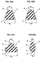
- Fig. 1 shows a flat surface of a gasket 1 corresponding to a rubber-like elastic part in accordance with a first comparative example, and an enlarged cross section (a cutoff end surface) along a line A-A thereof is shown in Fig. 2
- the gasket 1 in accordance with the comparative example is mounted around a connector in the HDD as shown in Figs. 20 and 21 mentioned above, seals between a base corresponding to one member and an FPC corresponding to the other member, and is structured as follows.
- an endless-shaped gasket main body 2 surrounding a circumference of the connector is provided by a rubber-like elastic body made of a predetermined rubber or a resin or the like, and a lug portion 3 is integrally formed at one position on a circumference of an outer peripheral surface of the gasket main body 2.
- the gasket main body 2 is structured such that a lip portion 5 having a triangular cross sectional shape or an approximately triangular cross sectional shape (in which a leading end contact surface 6 is formed in a round surface shape having a circular arc cross sectional shape) is integrally formed on one surface of a base portion 4 having a rectangular cross sectional shape or an approximately rectangular cross sectional shape (in which a leading end contact surface 7 is formed in a flat surface shape), as shown in Fig. 2 .
- An attachment member specifying structure is provided in such a manner that the gasket 1 is surely detached from the base so as to be attached to a side of the FPC at a time of detaching the base and the FPC from each other.
- the attachment member specifying structure is concretely structured such that a contact width w1 of the contact surface 6 in the side of the lip portion 5 with respect to the base is formed smaller than a contact width w2 of the contact surface 7 in the side of the base portion 4 with respect to the FPC, and a contact area of the contact surface 6 in the side of the lip portion 5 with respect to the base is formed smaller than a contact area of the contact surface 7 in the side of the base portion 4 with respect to the FPC. Accordingly, the gasket 1 is surely detached from the base so as to be attached to the side of the FPC, on the basis of difference of an adhesive force caused by difference of the contact width or the contact area between both the contact surfaces 6 and 7.
- the cross sectional shape of the gasket 1 is not particularly limited, but may be constituted, for example, in the following shapes.
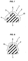
- Fig. 7 shows a cross section (a cutoff end surface) of a gasket 1 corresponding to a rubber-like elastic part in accordance with a second comparative example.
- the gasket 1 in accordance with the comparative example is mounted around a connector in the HDD as shown in Figs. 20 and 21 mentioned above, seals between a base corresponding to one member and an FPC corresponding to the other member, and is structured as follows.
- an endless-shaped gasket main body 2 surrounding a circumference of the connector is provided by a rubber-like elastic body made of a predetermined rubber or a resin or the like, and a lug portion (not shown) is integrally formed at one position on a circumference of the gasket main body 2.
- the gasket main body 2 is structured such that a lip portion 5 having a triangular cross sectional shape or an approximately triangular cross sectional shape (in which a leading end contact surface 6 is formed in a round surface shape having a circular arc cross sectional shape) is integrally formed on one surface of a base portion 4 having a rectangular cross sectional shape or an approximately rectangular cross sectional shape (in which a leading end contact surface 7 is formed in a flat surface shape).
- An attachment member specifying structure is provided in such a manner that the gasket 1 is surely detached from the base so as to be attached to a side of the FPC at a time of detaching the base and the FPC from each other.
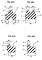
- the attachment member specifying structure is concretely structured such that a surface treated portion 10 constituted by matte finishing or the like is provided in the contact surface 6 in the side of the lip portion 5 with respect to the base.
- the surface treated portion 10 is provided in all the surface except the contact surface 7 in the side of the base portion 4 with respect to the FPC.
- a roughness of the matte finishing is between 3 and 20 ⁇ m, and preferably between 6 and 10 ⁇ m.
- the surface treated portion 10 constituted by the matte finishing or the like is provided in the contact surface 6 in the side of the base, a difference is made in a magnitude of the contact area between the base side and the FPC side, so that a difference is made in a magnitude of the adhesive force between the base side and the FPC side accordingly (the base side is small and the FPC side is large). Therefore, the gasket 1 is surely detached from the base so as to be attached to the side of the FPC.
- the cross sectional shape of the gasket 1 is not particularly limited, but may be constituted, for example, in a shape shown in each of Figs. 3A to 3D and 4A to 4D mentioned above.
- Fig. 8 shows an example thereof in which the cross sectional shape of the gasket main body 2 is formed in a trapezoidal shape or an approximately trapezoidal shape.
- Fig. 9 shows a cross section (a cutoff end surface) of a gasket 1 corresponding to a rubber-like elastic part in accordance with a third comparative example.
- the gasket 1 in accordance with the comparative example is mounted around a connector in the HDD as shown in Figs. 20 and 21 mentioned above, seals between a base corresponding to one member and an FPC corresponding to the other member, and is structured as follows.
- an endless-shaped gasket main body 2 surrounding a circumference of the connector is provided by a rubber-like elastic body made of a predetermined rubber or a resin or the like, and a lug portion (not shown) is integrally formed at one position on a circumference of the gasket main body 2.
- the gasket main body 2 is structured such that a lip portion 5 having a triangular cross sectional shape or an approximately triangular cross sectional shape (in which a leading end contact surface 6 is formed in a round surface shape having a circular arc cross sectional shape) is integrally formed on one surface of a base portion 4 having a rectangular cross sectional shape or an approximately rectangular cross sectional shape (in which a leading end contact surface 7 is formed in a flat surface shape).
- An attachment member specifying structure is provided in such a manner that the gasket 1 is surely detached from the base so as to be attached to a side of the FPC at a time of detaching the base and the FPC from each other.
- the attachment member specifying structure is concretely is structured such that a projection-like spring portion 11 elastically pressed to the base and achieving a spring effect is integrally formed in the gasket main body 4.
- the spring portion 11 is provided in the same side as that of the lip portion 5, and is formed in a rectangular cross sectional shape or an approximately rectangular cross sectional shape (in which a leading end surface is formed in a flat surface shape).
- the contact surface 6 in the side of the base is peeled from the base due to its elastic property, or becomes to be easily peeled at least, so that a difference is made in a magnitude of the adhesive force between the base side and the FPC side accordingly (the base side is small and the FPC side is large). Therefore, the gasket 1 is surely detached from the base so as to be attached to the side of the FPC.
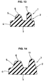
- a collapsing margin T1 of the spring portion 11 it is effective to set a collapsing margin T1 of the spring portion 11 to be larger than a collapsing margin T2 of the lip portion 5.
- a height of the spring portion 11 is generally formed larger than a height of the lip portion 5 due to the flat surface shape of the base portion 12 as shown in Fig. 10 .
- a step 13 or the like is provided in the base 12 as shown in Fig. 11 , there is a case that the height of the spring portion 11 is formed smaller than the height of the lip portion 5.
- the cross sectional shape of the gasket 1 is not particularly limited, and the following shapes may be employed, for example.
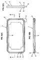
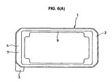
- Figs. 15A to 15C and 16A to 16B show a gasket 1 corresponding to a rubber-like elastic part in accordance with an embodiment of the present invention, in which Fig. 15A is a plan view thereof, Fig. 15B is a cross sectional view along a line D-D in Fig. 15A, Fig. 15C is a cross sectional view along a line E-E in Fig. 15A , Fig. 16A is a bottom view thereof, and Fig. 16B is a view as seen from a direction of an arrow F in Fig. 16A .
- the gasket 1 in accordance with the embodiment is mounted around the connector in the HDD as shown in Figs. 20 and 21 mentioned above, seals between the base corresponding to one member and the FPC corresponding to the other member, and is structured as follows.
- an endless-shaped gasket main body 2 surrounding a circumference of the connector is provided by a rubber-like elastic body made of a predetermined rubber or a resin or the like, and lug portions 3 are integrally formed at two positions on a circumference of an outer peripheral surface of the gasket main body 2.
- a thin plate-like flange portion 9 for positioning the gasket 1 with respect to the connector is integrally formed in an inner peripheral surface of the gasket main body 2, and ring-shaped rib portions 15 for positioning the gasket 1 with respect to the base are integrally formed within a flat surface of the flange portion 9.
- the gasket main body 2 is structured, as well shown in Fig. 15C , such that a lip portion 5 having a triangular cross sectional shape or an approximately triangular cross sectional shape (in which a leading end contact surface 6 is formed in a round surface shape having a circular arc cross sectional shape) is integrally formed on an outer peripheral edge portion of one surface of a base portion 4 having a rectangular cross sectional shape or an approximately rectangular cross sectional shape (in which a leading end contact surface 7 is formed in a flat surface shape).
- An attachment member specifying structure is provided in such a manner that the gasket 1 is surely detached from the base so as to be attached to a side of the FPC at a time of detaching the base and the FPC from each other.
- the attachment member specifying structure is concretely structured, in the same manner as the first comparative example mentioned above, such that the contact width of the contact surface 6 in the side of the lip portion 5 with respect to the base is formed smaller than the contact width of the contact surface 7 in the side of the base portion 4 with respect to the FPC, and the contact area of the contact surface 6 in the side of the lip portion 5 with respect to the base is formed smaller than the contact area of the contact surface 7 in the side of the base portion 4 with respect to the FPC. Accordingly, the gasket 1 is surely detached from the base and attached to the FPC side on the basis of the difference of the adhesive force caused by the difference of the contact width or the contact area between both the contact surfaces 6 and 7.
- the lug portion 3 is provided as a tab for preventing the gasket 1 from being erroneously assembled between inside and out.
- a groove (a recess portion) attaching the connector is provided in the base, and in the case that the gasket 1 is assembled contrarily between inside and out at a time of assembling the gasket 1 together with the connector in the groove, the lug portion 3 is interfered with the base and the assembly can not be finished. Accordingly, it is possible to notice the erroneous assembly.
- the lug portion 3 is provided in the FPC side contact surface 7 of the gasket 1 in a flush manner as shown in Fig. 16B , however, may be sometimes arranged at a middle position in the height direction (a lateral direction in the drawing) of the gasket 1 as shown in Fig. 5C .
- the lug portion 3 is provided as a tab for easily peeling the gasket 1 from the FPC.
- the gasket 1 is attached to the side of the FPC for working at a time of detaching the FPC from the base in the case of reworking as mentioned above, however, in the case that it is necessary to replace the gasket 1 due to a problem of the gasket 1 itself, it is hard to peel the gasket 1 from the FPC.
- the lug portion 3 is provided for easily peeling the gasket 1 in the case mentioned above.
- the gasket 1 can be easily peeled from the side of the FPC by arranging a detachment facilitating portion 17 constituted by the surface treated portion such as the matte finishing or the like in the FPC side contact surface 16 in the lug portion 3.
- the detachment facilitating portion 17 may be constituted by a recess portion, a convex portion or a combination thereof, in addition to the surface treated portion such as the matte finishing or the like, and may employ any structures as far as the adhesive force per unit area is set to be smaller than that of the FPC side contact surface 7.
- attachment member specifying structures described in the first to third comparative example and the embodiment can be employed in the following parts in addition to the connector gasket.
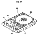
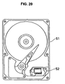
- Figs. 17 and 18 show a VCM damper 21 serving as one kind of a damping rubber corresponding to a rubber-like elastic part in accordance with a fourth, in which Fig. 17 is a perspective view of an attached state thereof, and Fig. 18 is a cross sectional view of the attached state thereof.
- the VCM damper 21 in accordance with the comparative example is used so as to be pinched between a top cover 23 corresponding to a casing part of the HDD 22 and a VCM 24 corresponding to an interior part of the HDD 22 with using no adhesive agent, and achieves a damping effect so as to lower a vibration generated at a time of actuating the VCM 24.
- An attachment member specifying structure is provided such that the VCM damper 21 is surely detached from one of the top cover 23 and the VCM 24 and is attached to the other (for example, detached from the top cover 23 and attached to the VCM 24) at a time of moving the top cover 23 and the VCM 24 apart from each other (at a time of opening the top cover 23).
- the attachment member specifying structure is concretely structured, for example, by forming a contact area in the VCM damper 21 with respect to the top cover 23 smaller than a contact area with respect to the VCM 24, forming a surface treated portion constituted by matte finishing or the like on a contact surface in the VCM damper 21 with respect to the top cover 23, or forming a projection-like spring portion elastically pressed to the top cover 23 so as to achieve a spring effect.
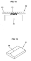
- the VCM damper 21 is generally formed in a flat plate shape as shown in Fig. 19 , it is preferable that a projection-like spring portion 25 is formed in a rib shape.
- the VCM 24 is structured such as to swing an arm 27 provided with a magnetic head 28 writing and reading the data with respect to a magnetic disc 26.
- the present invention achieves the following effects.
- the surface treated portion such as the matte finishing or the like, or the detachment facilitating portion constituted by the concavity and convexity or the like is provided in the contact surfaces with the other member in the lug portions of the rubber-like elastic member for the purpose of easily peeling the rubber-like elastic part from the other member,
Landscapes
- Engineering & Computer Science (AREA)
- General Engineering & Computer Science (AREA)
- Mechanical Engineering (AREA)
- Physics & Mathematics (AREA)
- Geometry (AREA)
- Chemical & Material Sciences (AREA)
- Combustion & Propulsion (AREA)
- Acoustics & Sound (AREA)
- Aviation & Aerospace Engineering (AREA)
- Gasket Seals (AREA)
Claims (7)
- Pièce élastique de type caoutchouc (1 ; 21) devant être serrée entre deux éléments opposés l'un à l'autre sans aucun agent adhésif, dans laquelle une structure de spécification d'élément d'attache est prévue de telle sorte que ladite pièce élastique de type caoutchouc (1 ; 21) peut être désolidarisée de manière sûre d'un élément et fixée sur l'autre élément au moment où l'on désolidarise lesdits deux éléments,
caractérisée en ce qu'une portion traitée superficiellement telle qu'un fini mat ou similaire, ou une portion facilitant la désolidarisation (17) constituée d'une concavité et convexité ou similaire, est prévue dans une surface de contact avec l'autre élément dans une portion de languette (3) dudit élément élastique de type caoutchouc de manière à pouvoir facilement peler ladite pièce élastique de type caoutchouc (1 ; 21) des autres éléments. - Pièce élastique de type caoutchouc (1 ; 21) selon la revendication 1, dans laquelle une zone de contact (6) avec un élément dans ladite pièce élastique de type caoutchouc (1 ; 21) est formée en étant plus petite qu'une zone de contact (7) avec l'autre élément de telle sorte que ladite pièce élastique de type caoutchouc (1 ; 21) peut être désolidarisée de manière sûre dudit un élément et fixée sur ledit autre élément au moment de la désolidarisation desdits deux éléments.
- Pièce élastique de type caoutchouc (1 ; 21) selon la revendication 1, dans laquelle une portion traitée superficiellement (10), formée par un fini mat ou similaire, est prévue dans une zone de contact (6) avec un élément dans ladite pièce élastique de type caoutchouc (1 ; 21) de telle sorte que ladite pièce élastique de type caoutchouc (1 ; 21) peut être désolidarisée de manière sûre dudit un élément et fixée sur l'autre élément au moment de la désolidarisation desdits deux éléments.
- Pièce élastique de type caoutchouc (1 ; 21) selon la revendication 1, comprenant en outre une portion de ressort (11 ; 25) de type saillie, devant être comprimée de manière élastique sur un élément de manière à atteindre un effet de ressort de telle sorte que ladite pièce élastique de type caoutchouc (1 ; 21) peut être désolidarisée de manière sûre dudit un élément et fixée sur l'autre élément au moment de la désolidarisation desdits deux éléments.
- Pièce élastique de type caoutchouc (1 ; 21) selon l'une quelconque des revendications 1 à 4, dans laquelle ladite pièce élastique de type caoutchouc (1 ; 21) est constituée de manière à être un joint d'étanchéité, ou un joint d'étanchéité destiné à un lecteur de disque dur.
- Pièce élastique de type caoutchouc (1 ; 21) selon l'une quelconque des revendications 1 à 4, dans laquelle ladite pièce élastique de type caoutchouc (1 ; 21) est constituée de manière à être un caoutchouc amortissant, ou un caoutchouc amortissant destiné à un lecteur de disque dur.
- Pièce élastique de type caoutchouc (1 ; 21) selon l'une quelconque des revendications 1 à 4, dans laquelle ladite pièce élastique de type caoutchouc (1 ; 21) est constituée de manière à être une pièce élastique de type caoutchouc (1 ; 21) destinée à un lecteur de disque dur.
Applications Claiming Priority (3)
| Application Number | Priority Date | Filing Date | Title |
|---|---|---|---|
| JP2002327771 | 2002-11-12 | ||
| JP2002327771A JP4238973B2 (ja) | 2002-05-17 | 2002-11-12 | ゴム状弾性部品 |
| PCT/JP2003/007867 WO2004044463A1 (fr) | 2002-11-12 | 2003-06-20 | Partie elastique de type caoutchouc |
Publications (3)
| Publication Number | Publication Date |
|---|---|
| EP1561978A1 EP1561978A1 (fr) | 2005-08-10 |
| EP1561978A4 EP1561978A4 (fr) | 2006-06-07 |
| EP1561978B1 true EP1561978B1 (fr) | 2008-04-09 |
Family
ID=32310527
Family Applications (1)
| Application Number | Title | Priority Date | Filing Date |
|---|---|---|---|
| EP03811057A Expired - Lifetime EP1561978B1 (fr) | 2002-11-12 | 2003-06-20 | Partie elastique de type caoutchouc |
Country Status (7)
| Country | Link |
|---|---|
| US (1) | US7959161B2 (fr) |
| EP (1) | EP1561978B1 (fr) |
| KR (1) | KR20050074949A (fr) |
| CN (1) | CN100417847C (fr) |
| AU (1) | AU2003244325A1 (fr) |
| DE (1) | DE60320297T2 (fr) |
| WO (1) | WO2004044463A1 (fr) |
Cited By (1)
| Publication number | Priority date | Publication date | Assignee | Title |
|---|---|---|---|---|
| EP3663745B1 (fr) * | 2011-11-11 | 2021-12-29 | Axis-Shield AS | Joint d'étanchéité de cartouche de dosage |
Families Citing this family (46)
| Publication number | Priority date | Publication date | Assignee | Title |
|---|---|---|---|---|
| JP2004076877A (ja) * | 2002-08-20 | 2004-03-11 | Nok Corp | ガスケット |
| DE102007030883A1 (de) * | 2007-07-03 | 2009-01-08 | Schaeffler Kg | Dichtung für eine hydrostatische Linearführung |
| JP5179120B2 (ja) * | 2007-08-24 | 2013-04-10 | 株式会社ブリヂストン | 多段ガスケット |
| US8991785B2 (en) * | 2007-10-26 | 2015-03-31 | Applied Materials, Inc. | Methods and apparatus for sealing a slit valve door |
| JP5081004B2 (ja) * | 2008-01-30 | 2012-11-21 | 日本メクトロン株式会社 | ガスケット |
| US8246055B2 (en) * | 2008-02-29 | 2012-08-21 | Zodiac Pool Systems, Inc. | Multi-lobed seal member |
| JP5173732B2 (ja) * | 2008-10-23 | 2013-04-03 | Nok株式会社 | ガスケット |
| JP5177690B2 (ja) * | 2009-06-12 | 2013-04-03 | 日本メクトロン株式会社 | 小型電子機器用防水ガスケット |
| JP5709096B2 (ja) | 2009-11-18 | 2015-04-30 | Smc株式会社 | 管継手 |
| CN102742090B (zh) * | 2009-11-30 | 2016-01-13 | 富加宜汽车控股公司 | 密封件、包括该密封件的系统和连接器组件、组装和制造方法 |
| US9457941B2 (en) * | 2010-02-03 | 2016-10-04 | Tomoya Kawakami | Multipurpose elastic loop gasket |
| US8331084B2 (en) * | 2010-05-13 | 2012-12-11 | General Electric Company | Apparatus for securing electronic equipment |
| CN101839342A (zh) * | 2010-05-31 | 2010-09-22 | 海洋王照明科技股份有限公司 | 一种弹性密封件 |
| WO2012056768A1 (fr) * | 2010-10-26 | 2012-05-03 | Nok株式会社 | Joint d'étanchéité |
| JP5623251B2 (ja) * | 2010-11-12 | 2014-11-12 | 株式会社マキタ | バッテリパック |
| JP5760411B2 (ja) * | 2010-12-08 | 2015-08-12 | Nok株式会社 | ガスケット |
| CN103115067B (zh) * | 2011-11-16 | 2016-09-07 | 株式会社捷太格特 | 球窝接头 |
| JP5173011B1 (ja) * | 2011-11-25 | 2013-03-27 | 日本バルカー工業株式会社 | ゲート弁 |
| JP5425954B2 (ja) * | 2012-03-14 | 2014-02-26 | 石川ガスケット株式会社 | ガスケット用ラバーリング |
| US20140001033A1 (en) * | 2012-07-02 | 2014-01-02 | Arthur Jeffs | Hydrogen fuel assist device for an internal combustion engine and related methods |
| FR2995961B1 (fr) * | 2012-09-26 | 2014-10-17 | Joint Francais | Joint annulaire, et moule de fabrication d'un tel joint. |
| JP6104927B2 (ja) * | 2012-10-09 | 2017-03-29 | 日本バルカー工業株式会社 | 複合シール |
| JP2014092191A (ja) * | 2012-11-01 | 2014-05-19 | Nok Corp | 基材一体型シール及びその製造用金型 |
| JP6249557B2 (ja) * | 2012-12-19 | 2017-12-20 | 株式会社堀場エステック | シール部材、及び、シール部材の製造方法 |
| DE102013100028A1 (de) * | 2013-01-03 | 2014-07-03 | Harting Electric Gmbh & Co. Kg | Umweltdichtes Steckverbindergehäuse |
| US9423031B2 (en) * | 2013-10-30 | 2016-08-23 | Proserv Operations, Inc. | Key seal and valve |
| US9982511B2 (en) | 2014-01-03 | 2018-05-29 | Proserv Operations, Inc. | Dirty fluid pressure regulator and control valve |
| PL3215882T3 (pl) * | 2014-11-04 | 2020-07-13 | CommScope Connectivity Belgium BVBA | Obudowa do stosowania w światłowodowej sieci rozdzielczej |
| JP6350373B2 (ja) * | 2015-04-17 | 2018-07-04 | 株式会社デンソー | 蒸発器 |
| US10670155B2 (en) | 2015-10-05 | 2020-06-02 | Proserv Gilmore Valve Llc | Latching poppet valve |
| US10487951B2 (en) | 2016-01-22 | 2019-11-26 | Proserv Operations, Inc. | Non-interflow directional control valve |
| US9976657B2 (en) * | 2016-04-01 | 2018-05-22 | Cameron International Corporation | Double slip seal profile for plug valves |
| US10591076B2 (en) | 2016-09-15 | 2020-03-17 | Proserv Operations, Inc. | Low friction hydraulic circuit control components |
| DE102016121343A1 (de) * | 2016-11-08 | 2018-05-09 | C. Otto Gehrckens GmbH & Co. KG | Formwerkzeug zur Herstellung von faserverstärkten Kunststoffteilen, Dichtung für ein derartiges Formwerkzeug und Verfahren zum Abdichten eines derartigen Formwerkzeuges |
| US10633951B2 (en) | 2017-09-22 | 2020-04-28 | Proserv Operations, Inc. | Pressure regulator with user selectable dampening |
| US10739796B2 (en) | 2017-09-22 | 2020-08-11 | Proserv Gilmore Valve Llc | Pressure regulator with reconfigurable hydraulic dampening |
| WO2019082499A1 (fr) * | 2017-10-24 | 2019-05-02 | Nok株式会社 | Joint d'étanchéité |
| US10373652B2 (en) * | 2017-11-10 | 2019-08-06 | Seagate Technology Llc | Disk drive cover with spring force compression feature |
| US11022226B2 (en) | 2018-03-20 | 2021-06-01 | Proserv Operations, Inc. | Microfluidic valve |
| US11054050B2 (en) | 2018-08-13 | 2021-07-06 | Proserv Operations Inc. | Valve with press-fit insert |
| US11209096B2 (en) | 2018-11-19 | 2021-12-28 | Proserv Operations, Inc. | Bilateral and throttling directional control valve |
| US10622027B1 (en) * | 2018-11-28 | 2020-04-14 | Western Digital Technologies, Inc. | Magnetic storage device with improved top cover gasket and associated method of manufacture |
| US11261982B2 (en) | 2019-06-27 | 2022-03-01 | Proserv Gilmore Valve Llc | Pressure relief valve with bi-directional seat |
| CN112923055A (zh) * | 2019-12-05 | 2021-06-08 | 无锡恩福油封有限公司 | 密封装置及密封结构 |
| US11828370B2 (en) | 2020-01-02 | 2023-11-28 | Proserv Gilmore Valve Llc | Check valve with conforming seat |
| GB2609415A (en) * | 2021-07-29 | 2023-02-08 | Airbus Operations Ltd | Seal |
Family Cites Families (82)
| Publication number | Priority date | Publication date | Assignee | Title |
|---|---|---|---|---|
| US1883609A (en) * | 1930-05-31 | 1932-10-18 | William J Dennis | Gasket |
| US2058010A (en) * | 1934-08-04 | 1936-10-20 | Westinghouse Air Brake Co | Gasket |
| US2091913A (en) * | 1935-11-15 | 1937-08-31 | Boston Woven Hose & Rubber Cor | Rubber sealing ring |
| US2210183A (en) * | 1938-03-18 | 1940-08-06 | Schweighart Raymond | Silverware chest |
| US2383570A (en) * | 1942-11-23 | 1945-08-28 | David M Sellew | Hydrocarbon resistant, light pressure sealing gasket structure |
| US2445952A (en) * | 1946-11-19 | 1948-07-27 | Lagergren Henning | Sealing ring |
| US2661229A (en) * | 1950-12-02 | 1953-12-01 | Crane & Breed Casket Company | Sealing gasket |
| US2777282A (en) * | 1952-05-12 | 1957-01-15 | Piquerez Erwin | Fluidtight watchcase |
| US3166332A (en) * | 1961-05-26 | 1965-01-19 | Olson Richard Laurence | Pressure assembly comprising a sealing strip of elastomeric material having compressible gas cells |
| US3750411A (en) * | 1970-04-16 | 1973-08-07 | S Shimizu | Joint for under-water structures |
| DE2120862A1 (de) * | 1971-04-28 | 1972-11-09 | Farbenfabriken Bayer Ag, 5090 Leverkusen | 3,5-Disubstituierte 2-Acyloxybenzoesäureanilide, Verfahren zu ihrer Herstellung und ihre insektizide und akarizide Verwendung |
| US3892417A (en) * | 1973-08-27 | 1975-07-01 | American Funeral Supply Corp | Gasket for sealing a casket |
| US3991897A (en) * | 1975-10-02 | 1976-11-16 | Meyers Ronald B | Canning jar lid and sealing system |
| JPS5824047Y2 (ja) * | 1978-01-30 | 1983-05-23 | トヨタ自動車株式会社 | シ−ル構造 |
| US4358443A (en) * | 1980-04-14 | 1982-11-09 | The Research Foundation Of State University Of New York | Method and composition for controlling the growth of microorganisms |
| JPS5881269A (ja) * | 1981-11-05 | 1983-05-16 | Arai Pump Mfg Co Ltd | 低摩擦性oリング |
| DE3225361C2 (de) * | 1982-07-07 | 1984-04-26 | Leybold-Heraeus GmbH, 5000 Köln | Verfahren zur Herstellung einer Metalldichtung für Flanschverbindungen |
| JPS59118750A (ja) * | 1982-12-27 | 1984-07-09 | Eisai Co Ltd | カルボン酸アミド化合物およびその誘導体 |
| US4742083A (en) * | 1983-08-24 | 1988-05-03 | Lever Brothers Company | Method of relieving pain and inflammatory conditions employing substituted salicylamides |
| US4725590A (en) * | 1983-08-24 | 1988-02-16 | Lever Brothers Company | Method of relieving pain and inflammatory conditions employing substituted salicylamides |
| US4560549A (en) * | 1983-08-24 | 1985-12-24 | Lever Brothers Company | Method of relieving pain and inflammatory conditions employing substituted salicylamides |
| US4715609A (en) * | 1984-12-07 | 1987-12-29 | Diesel Kiki Co., Ltd. | Seal element for sealing ducts of an air conditioner system |
| JPS6230780A (ja) * | 1985-04-17 | 1987-02-09 | Ss Pharmaceut Co Ltd | 1,7−ナフチリジン誘導体及びこれを含有する薬剤 |
| US4939133A (en) * | 1985-10-01 | 1990-07-03 | Warner-Lambert Company | N-substituted-2-hydroxy-α-oxo-benzeneacetamides and pharmaceutical compositions having activity as modulators of the arachidonic acid cascade |
| JPS62134967A (ja) | 1985-12-09 | 1987-06-18 | Fuji Electric Co Ltd | 密着型イメ−ジセンサ |
| JPH0446111Y2 (fr) * | 1986-02-18 | 1992-10-29 | ||
| US4758004A (en) * | 1986-10-02 | 1988-07-19 | Casket Shells, Inc. | Casket sealing gasket having sealing ridges of different heights |
| US4952588A (en) * | 1987-11-27 | 1990-08-28 | Hoechst-Roussel Pharmaceuticals Inc. | 1-aryl-3-quinoline-and 1-aryl-3-isoquinoline-carboxamides |
| US4786644A (en) * | 1987-11-27 | 1988-11-22 | Hoechst-Roussel Pharmaceuticals Inc. | 1-aryl-3-quinolinecarboxamide |
| US4966906A (en) * | 1987-11-27 | 1990-10-30 | Hoechst-Roussel Pharmaceuticals Inc. | 1-aryl-3-isoquinolinecarboxamides |
| FR2627835B1 (fr) * | 1988-02-26 | 1991-05-17 | Hutchinson | Coulisse d'etancheite de glace mobile, notamment de vitre de vehicule automobile |
| US4934715A (en) * | 1989-01-09 | 1990-06-19 | Johnson Roy E | Gasket for use with manhole covers |
| FR2644217A1 (fr) * | 1989-03-07 | 1990-09-14 | Procal | Joint d'etancheite statique |
| JP2988739B2 (ja) * | 1990-04-16 | 1999-12-13 | 協和醗酵工業株式会社 | 1,8−ナフチリジン−2−オン誘導体 |
| US5093968A (en) * | 1990-10-01 | 1992-03-10 | Batesville Casket Company, Inc. | Gasket and one-way valve for a casket |
| US5090713A (en) * | 1990-12-24 | 1992-02-25 | Johnson Roy E | Elastomeric gasket for sealing a glass fiber reinforced cover to a vault |
| CZ285937B6 (cs) * | 1992-01-16 | 1999-12-15 | Hoechst Aktiengesellschaft | Arylcykloalkylové deriváty, způsob přípravy těchto derivátů a jejich použití |
| US6159988A (en) * | 1992-01-16 | 2000-12-12 | Hoeschst Aktiengesellschaft | Arylcycloalkyl derivatives, their production and their use |
| JPH05288116A (ja) * | 1992-04-10 | 1993-11-02 | Toyoda Gosei Co Ltd | ガスケット |
| JP2787637B2 (ja) * | 1992-06-23 | 1998-08-20 | 富士通株式会社 | 印字ヘッド |
| JP2576785Y2 (ja) * | 1993-02-22 | 1998-07-16 | 矢崎総業株式会社 | 防水コネクタの嵌合構造 |
| JPH07132961A (ja) * | 1993-11-04 | 1995-05-23 | Nitto Denko Corp | セパレータもしくは包装用材料 |
| US5511518A (en) * | 1994-11-02 | 1996-04-30 | Fel-Pro Incorporated | Sealing assembly with undercut groove |
| DE29504752U1 (de) * | 1995-03-20 | 1996-07-18 | Robert Bosch Gmbh, 70469 Stuttgart | Steckkupplung, insbesondere für elektrische Kleinspannungsanlagen |
| US5551705A (en) * | 1995-07-12 | 1996-09-03 | Fel-Pro Incorporated | Double beaded spaghetti seal with stiffness increasing deformation behavior |
| US5811428A (en) * | 1995-12-18 | 1998-09-22 | Signal Pharmaceuticals, Inc. | Pyrimidine carboxamides and related compounds and methods for treating inflammatory conditions |
| US5852028A (en) * | 1995-12-18 | 1998-12-22 | Signal Pharmaceuticals, Inc. | Pyrimidine carboxylates and related compounds and methods for treating inflammatory conditions |
| US5935966A (en) * | 1995-09-01 | 1999-08-10 | Signal Pharmaceuticals, Inc. | Pyrimidine carboxylates and related compounds and methods for treating inflammatory conditions |
| JPH0982402A (ja) * | 1995-09-07 | 1997-03-28 | Yazaki Corp | シールパッキン及び機器直付けコネクタ |
| JP3454628B2 (ja) | 1996-01-25 | 2003-10-06 | 義一 高山 | シール |
| JPH09282860A (ja) | 1996-04-12 | 1997-10-31 | Nippon Mektron Ltd | ハードディスク装置用ガスケット |
| US5981047A (en) * | 1996-06-25 | 1999-11-09 | Applied Extrusion Technologies, Inc. | Matte finish biaxially oriented polypropylene film for cold seal release applications |
| DE19651288A1 (de) * | 1996-12-10 | 1997-07-24 | Lucas Hans Guenter | Strahlwasserdichte Kunststoffhauben für D-Sub-Steckverbinder |
| JPH10234865A (ja) | 1997-02-27 | 1998-09-08 | Ooshin Seiyaku Kk | 低周波治療用粘着シート及びこれを用いた低周波治療器 |
| US6045140A (en) * | 1997-07-11 | 2000-04-04 | Cummins Engine Company, Inc. | Retention gasket with cooperating cover |
| JP3843168B2 (ja) * | 1997-07-30 | 2006-11-08 | 曙ブレーキ工業株式会社 | ディスクブレーキ装置 |
| JPH11126648A (ja) * | 1997-10-21 | 1999-05-11 | Yazaki Corp | パッキンの保持構造 |
| US6117859A (en) * | 1997-11-04 | 2000-09-12 | The Research Foundation Of State University Of New York | Method of relieving chronic inflammation by using 5-alkylsulfonylsalicylanilides |
| US6022884A (en) * | 1997-11-07 | 2000-02-08 | Amgen Inc. | Substituted pyridine compounds and methods of use |
| US6225329B1 (en) * | 1998-03-12 | 2001-05-01 | Novo Nordisk A/S | Modulators of protein tyrosine phosphatases (PTPases) |
| US20020002199A1 (en) * | 1998-03-12 | 2002-01-03 | Lone Jeppesen | Modulators of protein tyrosine phosphatases (ptpases) |
| US20020019412A1 (en) * | 1998-03-12 | 2002-02-14 | Henrik Sune Andersen | Modulators of protein tyrosine phosphatases (ptpases) |
| US6262044B1 (en) * | 1998-03-12 | 2001-07-17 | Novo Nordisk A/S | Modulators of protein tyrosine phosphatases (PTPASES) |
| DE69917201T2 (de) * | 1998-07-22 | 2005-05-04 | Daiichi Suntory Pharma Co., Ltd. | Nf-kappa b inhibitoren, die indanderivate als aktiven bestandteil enthalten |
| US6328316B1 (en) * | 1999-01-12 | 2001-12-11 | Dupont Dow Elastomers, L.L.C. | Rubber seal for semi-dynamic applications |
| JP3349132B2 (ja) * | 1999-04-12 | 2002-11-20 | 三菱電線工業株式会社 | 低荷重シール |
| US6653309B1 (en) * | 1999-04-26 | 2003-11-25 | Vertex Pharmaceuticals Incorporated | Inhibitors of IMPDH enzyme technical field of the invention |
| AU5247100A (en) * | 1999-07-13 | 2001-01-30 | Nok Corporation | Gasket for fuel cell and method of forming it |
| JP4691295B2 (ja) * | 1999-08-11 | 2011-06-01 | 株式会社シグナル・クリエーション | サリチル酸アミド誘導体 |
| US6787652B1 (en) * | 1999-09-30 | 2004-09-07 | Pfizer, Inc. | 6-Azauracil derivatives as thyroid receptor ligands |
| JP2001108106A (ja) * | 1999-10-05 | 2001-04-20 | Nok Corp | ハードディスクドライブ用ガスケットおよびその製造方法 |
| JP4719336B2 (ja) * | 2000-04-20 | 2011-07-06 | 電気化学工業株式会社 | ブチルゴム複合シール材 |
| JP2001311470A (ja) | 2000-04-28 | 2001-11-09 | Nok Corp | カバーガスケット |
| US6414013B1 (en) * | 2000-06-19 | 2002-07-02 | Pharmacia & Upjohn S.P.A. | Thiophene compounds, process for preparing the same, and pharmaceutical compositions containing the same background of the invention |
| US6761360B2 (en) * | 2000-07-07 | 2004-07-13 | Parker-Hannifin Corporation | Interference-fit retainer gasket |
| WO2002049632A1 (fr) * | 2000-12-18 | 2002-06-27 | Institute Of Medicinal Molecular Design. Inc. | Inhibiteurs de production et de liberation de cytokines inflammatoires |
| WO2002051397A1 (fr) * | 2000-12-22 | 2002-07-04 | Ishihara Sangyo Kaisha, Ltd. | Derives d'aniline ou sels de ceux-ci, ainsi qu'inhibiteurs de production de cytokine contenant ces derives |
| HUP0302479A2 (hu) * | 2001-03-27 | 2003-11-28 | Daiichi Suntory Biomedical Research Limited | NF-kappa B gátló gyógyszerkészítmény, amely hatóanyagként helyettesített benzoesavszármazékot tartalmaz |
| JP2003287139A (ja) * | 2002-03-29 | 2003-10-10 | Uchiyama Mfg Corp | ガスケット |
| EP1510210A4 (fr) * | 2002-06-05 | 2009-01-07 | Inst Med Molecular Design Inc | Inhibiteurs de proteines-kinases en relation a l'immunite |
| TW200307535A (en) * | 2002-06-10 | 2003-12-16 | Inst Med Molecular Design Inc | Therapeutic agent for cancer |
| JP2004076877A (ja) * | 2002-08-20 | 2004-03-11 | Nok Corp | ガスケット |
-
2003
- 2003-06-20 CN CNB038155117A patent/CN100417847C/zh not_active Expired - Fee Related
- 2003-06-20 WO PCT/JP2003/007867 patent/WO2004044463A1/fr active IP Right Grant
- 2003-06-20 DE DE60320297T patent/DE60320297T2/de not_active Expired - Lifetime
- 2003-06-20 US US10/515,294 patent/US7959161B2/en not_active Expired - Fee Related
- 2003-06-20 EP EP03811057A patent/EP1561978B1/fr not_active Expired - Lifetime
- 2003-06-20 AU AU2003244325A patent/AU2003244325A1/en not_active Abandoned
- 2003-06-20 KR KR1020057000728A patent/KR20050074949A/ko not_active Application Discontinuation
Cited By (1)
| Publication number | Priority date | Publication date | Assignee | Title |
|---|---|---|---|---|
| EP3663745B1 (fr) * | 2011-11-11 | 2021-12-29 | Axis-Shield AS | Joint d'étanchéité de cartouche de dosage |
Also Published As
| Publication number | Publication date |
|---|---|
| CN100417847C (zh) | 2008-09-10 |
| KR20050074949A (ko) | 2005-07-19 |
| AU2003244325A1 (en) | 2004-06-03 |
| US7959161B2 (en) | 2011-06-14 |
| WO2004044463A1 (fr) | 2004-05-27 |
| CN1666048A (zh) | 2005-09-07 |
| EP1561978A4 (fr) | 2006-06-07 |
| EP1561978A1 (fr) | 2005-08-10 |
| US20050225039A1 (en) | 2005-10-13 |
| DE60320297D1 (de) | 2008-05-21 |
| DE60320297T2 (de) | 2009-07-16 |
Similar Documents
| Publication | Publication Date | Title |
|---|---|---|
| EP1561978B1 (fr) | Partie elastique de type caoutchouc | |
| EP1533549B1 (fr) | Joint d'etancheite | |
| EP1847734B1 (fr) | Joint statique et structure pour assurer l'étanchéité entre deux éléments | |
| US6347021B2 (en) | Component sealing system | |
| EP1850039A1 (fr) | Structure d'etancheite utilisant un joint | |
| JP4238973B2 (ja) | ゴム状弾性部品 | |
| JP3533330B2 (ja) | 情報処理装置の耐環境カバー | |
| JPH10322046A (ja) | シール構造 | |
| JP2009074643A (ja) | 電子機器のシール構造 | |
| EP3030063A1 (fr) | Boîtier pour unité de commande électronique | |
| JP4758292B2 (ja) | ウェザーストリップ | |
| JPH09159027A (ja) | カバー用ガスケット | |
| JP2002347438A (ja) | ウインドウパネルの取付構造 | |
| JP2008044461A (ja) | 外装部品用保護部材 | |
| JPH0617341Y2 (ja) | 電気機器収納ボックスのガスケット部構造 | |
| JP2004068998A (ja) | ガスケットの取付構造およびその取付方法 | |
| JP4702786B2 (ja) | 自動車用ウィンドモール | |
| JP2004291704A (ja) | 自動車用ドアモール | |
| JP4083964B2 (ja) | 支管継手 | |
| JP3818006B2 (ja) | グロメット | |
| JP3801590B2 (ja) | 窓ガラスに対する結露防止パネルの取り付け方法。 | |
| JP2001027329A (ja) | 密封装置 | |
| JP4675744B2 (ja) | スペアタイヤカバー | |
| JP2006250190A (ja) | ゴム状弾性部品およびその製造方法 | |
| JP2010221734A (ja) | ウェザーストリップの取付構造 |
Legal Events
| Date | Code | Title | Description |
|---|---|---|---|
| PUAI | Public reference made under article 153(3) epc to a published international application that has entered the european phase |
Free format text: ORIGINAL CODE: 0009012 |
|
| 17P | Request for examination filed |
Effective date: 20041130 |
|
| AK | Designated contracting states |
Kind code of ref document: A1 Designated state(s): AT BE BG CH CY CZ DE DK EE ES FI FR GB GR HU IE IT LI LU MC NL PT RO SE SI SK TR |
|
| AX | Request for extension of the european patent |
Extension state: AL LT LV MK |
|
| DAX | Request for extension of the european patent (deleted) | ||
| RBV | Designated contracting states (corrected) |
Designated state(s): DE FR |
|
| A4 | Supplementary search report drawn up and despatched |
Effective date: 20060426 |
|
| 17Q | First examination report despatched |
Effective date: 20061023 |
|
| RIN1 | Information on inventor provided before grant (corrected) |
Inventor name: SEKI, SHOTA Inventor name: KISHIMOTO, MASAYUKIC/O NOK CORPORATION |
|
| GRAP | Despatch of communication of intention to grant a patent |
Free format text: ORIGINAL CODE: EPIDOSNIGR1 |
|
| GRAS | Grant fee paid |
Free format text: ORIGINAL CODE: EPIDOSNIGR3 |
|
| GRAA | (expected) grant |
Free format text: ORIGINAL CODE: 0009210 |
|
| AK | Designated contracting states |
Kind code of ref document: B1 Designated state(s): DE FR |
|
| REF | Corresponds to: |
Ref document number: 60320297 Country of ref document: DE Date of ref document: 20080521 Kind code of ref document: P |
|
| PGFP | Annual fee paid to national office [announced via postgrant information from national office to epo] |
Ref country code: FR Payment date: 20080618 Year of fee payment: 6 |
|
| ET | Fr: translation filed | ||
| PLBE | No opposition filed within time limit |
Free format text: ORIGINAL CODE: 0009261 |
|
| STAA | Information on the status of an ep patent application or granted ep patent |
Free format text: STATUS: NO OPPOSITION FILED WITHIN TIME LIMIT |
|
| 26N | No opposition filed |
Effective date: 20090112 |
|
| REG | Reference to a national code |
Ref country code: FR Ref legal event code: ST Effective date: 20100226 |
|
| PG25 | Lapsed in a contracting state [announced via postgrant information from national office to epo] |
Ref country code: FR Free format text: LAPSE BECAUSE OF NON-PAYMENT OF DUE FEES Effective date: 20090630 |
|
| PGFP | Annual fee paid to national office [announced via postgrant information from national office to epo] |
Ref country code: DE Payment date: 20100616 Year of fee payment: 8 |
|
| REG | Reference to a national code |
Ref country code: DE Ref legal event code: R119 Ref document number: 60320297 Country of ref document: DE Effective date: 20120103 |
|
| PG25 | Lapsed in a contracting state [announced via postgrant information from national office to epo] |
Ref country code: DE Free format text: LAPSE BECAUSE OF NON-PAYMENT OF DUE FEES Effective date: 20120103 |