EP1557362B1 - Methode et dispositif pour enlever le couvercle d'un boîtier - Google Patents
Methode et dispositif pour enlever le couvercle d'un boîtier Download PDFInfo
- Publication number
- EP1557362B1 EP1557362B1 EP04030386A EP04030386A EP1557362B1 EP 1557362 B1 EP1557362 B1 EP 1557362B1 EP 04030386 A EP04030386 A EP 04030386A EP 04030386 A EP04030386 A EP 04030386A EP 1557362 B1 EP1557362 B1 EP 1557362B1
- Authority
- EP
- European Patent Office
- Prior art keywords
- cover
- suction
- storage box
- roller
- region
- Prior art date
- Legal status (The legal status is an assumption and is not a legal conclusion. Google has not performed a legal analysis and makes no representation as to the accuracy of the status listed.)
- Expired - Lifetime
Links
- 238000000034 method Methods 0.000 title claims description 23
- 238000004804 winding Methods 0.000 claims description 21
- 238000010438 heat treatment Methods 0.000 claims description 17
- 239000000853 adhesive Substances 0.000 claims description 11
- 230000001070 adhesive effect Effects 0.000 claims description 11
- 230000032258 transport Effects 0.000 claims description 10
- 230000005855 radiation Effects 0.000 claims description 5
- 238000007599 discharging Methods 0.000 claims 8
- 230000003247 decreasing effect Effects 0.000 claims 3
- 238000011144 upstream manufacturing Methods 0.000 claims 2
- 230000000717 retained effect Effects 0.000 claims 1
- 238000002347 injection Methods 0.000 abstract 1
- 239000007924 injection Substances 0.000 abstract 1
- 230000002093 peripheral effect Effects 0.000 description 3
- 238000005096 rolling process Methods 0.000 description 3
- 239000012212 insulator Substances 0.000 description 2
- 238000004806 packaging method and process Methods 0.000 description 2
- 238000007789 sealing Methods 0.000 description 2
- 230000001419 dependent effect Effects 0.000 description 1
- 238000003780 insertion Methods 0.000 description 1
- 230000037431 insertion Effects 0.000 description 1
- 230000000284 resting effect Effects 0.000 description 1
- 230000002441 reversible effect Effects 0.000 description 1
- 230000001954 sterilising effect Effects 0.000 description 1
- 238000004659 sterilization and disinfection Methods 0.000 description 1
- 239000003206 sterilizing agent Substances 0.000 description 1
Images

Classifications
-
- B—PERFORMING OPERATIONS; TRANSPORTING
- B65—CONVEYING; PACKING; STORING; HANDLING THIN OR FILAMENTARY MATERIAL
- B65B—MACHINES, APPARATUS OR DEVICES FOR, OR METHODS OF, PACKAGING ARTICLES OR MATERIALS; UNPACKING
- B65B69/00—Unpacking of articles or materials, not otherwise provided for
-
- B—PERFORMING OPERATIONS; TRANSPORTING
- B65—CONVEYING; PACKING; STORING; HANDLING THIN OR FILAMENTARY MATERIAL
- B65B—MACHINES, APPARATUS OR DEVICES FOR, OR METHODS OF, PACKAGING ARTICLES OR MATERIALS; UNPACKING
- B65B69/00—Unpacking of articles or materials, not otherwise provided for
- B65B69/0025—Removing or cutting binding material, e.g. straps or bands
Definitions
- the invention relates to a method for removing a cover from a magazine box, in particular from a magazine box equipped with prefabricated disposable syringes, with the other features in claim 1.
- a device for removing the cover of magazine boxes is also known (US Pat. DE 44 19 475 A1 ), which has a first gripping device with gripping jaws and a moving device and other complex mechanical means for removing the upper cover.
- a secure gripping the top cover is not always guaranteed even with such a device, for. B. because the cover, which protrudes only a few mm beyond the edge of the magazine boxes at the corners, sometimes bent upwards or downwards and therefore can not be seized safely.
- a second mechanical gripping device or instead of this a lifting device can be provided which has at least one suction cup on a swivel arm, which is connected to a suction device.
- the invention has for its object to provide a method of the type mentioned above, which allows removal of a cover from a magazine box in a reliable manner under sterile conditions.
- the object is achieved in a method of the type mentioned according to the invention by the features in claim 1.
- the invention makes use of the fact that adhesive bonds have the least resistance to peeling and therefore peeling with little effort and in a reliable manner without risk of tearing even with covers of magazine boxes with great advantage is possible. It is advantageous if the reduction of the adhesive strength of the cover in the area of a seal of some closure edges, such as the transverse edges takes place.
- the reduction of the adhesive strength of the cover can be done in an advantageous manner by heating at least in the region of some closure edges, such as the transverse edges. It may be advantageous in this case if the cover is acted upon by heating heat acting on it, at least in the region of some closure edges, in particular the transverse edges, in particular a heating radiation.
- the cover is acted upon by a suction force acting thereon and detached from the magazine box by means of this suction force, wherein the cover is subjected to a suction force at least in the region of a transverse edge and is detached by the suction force at least in the region of this transverse edge from the associated transverse edge of the magazine box.
- the cover is going through Unwinding from the magazine box peeled off.
- the cover is separated by peeling in the region of the closure edges of the magazine box, which is thereby held down at the same time.
- the Saugkraftbeierschlagung simultaneously peeling the cover can be initiated by winding, the winding of the cover can be done on a roll located above the magazine box.
- the Saugkraftbeaufschlagung can be replaced by z. B. along at least one row of the roller arranged suction devices, in particular suction cups, od connected to a vacuum source suction openings.
- the detached from the magazine box and wound cover can be unwound out of the range of the magazine box in the opposite direction or in the same direction to the winding and released with drop of Saugkraftbeaufschlagung and discharged through a dispensing opening.
- a lid-like top cover which is sealed to the edge of the magazine box is reliably, quickly and economically removable under sterile conditions.
- this cover is acted upon by a suction force acting thereon and removed by means of this suction force from the magazine box.
- the cover is acted upon at least in the region of a transverse edge with a suction force and raised by the suction force.
- the cover is then removed by winding from the magazine box.
- the Saugkraftbeaufschlagung done by z. B. along at least one row of the roller arranged suction devices, in particular suction cups, od connected to a vacuum source suction openings.
- those magazine boxes which contain both an upper cover sealed at the edge and a further loosely inserted cover can also be treated in the manner described. It is advantageous if, in a continuous sequence during passage of magazine boxes in a first stage, a first cover with reduction of adhesive strength or coverage in the region of some closure edges, especially the transverse edges, and peeled off peel off the magazine box and in a subsequent second stages one second, loosely located in the magazine box cover is removed from the magazine box. It may be advantageous if the detached and wound first cover and at least approximately at the same time the removed and wound second cover outside the range of Magazinkastens, preferably in opposite directions, unwound and delivered with a drop of the respective Saugkraftbeetzschung in a common output port.
- the invention further provides a device for removing at least one cover from a magazine box with the features of claim 15. Further advantageous features of the invention and embodiments thereof will become apparent from the subsequent dependent claims.
- This device allows for sterile treatment by placement within an insulator. Manual manipulations by an operator are not required, as the device enables automatic continuous operation. It is the Device compact, simple, reliable and cost-effective due to its simple design.
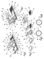
- a device 10 is shown, which is designed for removing at least one cover 11 and 12 of individual magazine boxes 13.
- These magazine boxes 13 are preferably those which are equipped with prefabricated, not yet filled disposable syringes 14. These are in the magazine box 13 z. B. arranged on a perforated support plate hanging, which are laid loosely on a circumferential shoulder of the side walls of the magazine boxes 13.
- the magazine boxes 13 After insertion, the magazine boxes 13 have been closed with a cover-like cover 11 which has been connected to the peripheral edge 15 of the magazine box 13 by sealing.
- the cover 11 and this edge-side connection along the edge 15 must be germ-tight, on the other hand, the cover 11 but can be solved by the edge 15, without causing the cover 11 tears or splits and remain parts thereof.
- each magazine box 13 is still provided with a second cover 12, which is introduced prior to attaching the first cover 11 in the magazine box 13 and loosely placed on the disposable syringes 14.
- the magazine boxes 13 are delivered. So that the disposable syringes contained in the magazine boxes 13 can now be filled and closed in a filling and closing device, the first cover 11 and possibly the second cover 12 must be removed beforehand. This is done by means of the device 10.
- the device 10 has a the magazine boxes 13 at intervals from each other preferably continuously along a path, which is simplified by an arrow 16, transporting transport device 17, the z. B. a particular straight running roller conveyor 9, on which the individual magazine boxes 13 with their in the direction approximately parallel to the arrow 16 extending longitudinal edges z. B. loosely and in the transport direction according to arrow 16 are moved forward. Furthermore, the device 10 has at least one Rolling station 18 with at least one at least one cover 11 by suction absorbing and retaining suction device 19 and at least one of these detained cover 11 winding roll 20 on.
- the roller station 18 has two rollers 20 and 21, which are arranged approximately parallel to one another and at the same height, wherein the rollers 20, 21 are arranged in the transport direction according to arrow 16 at a distance one behind the other.
- Each roller 20, 21 is associated with a drive 22 and 23, which is preferably reversible in terms of its direction of rotation.
- the respective suction device 19, 24 per roller 20 and 21 has z. B. along at least one row of the roller 20, 21 arranged suction devices, in particular suction cups, od connected to a vacuum source not shown od.
- suction device 19 and 24 suction openings in the shell of the respective roller 20 and 21 are indicated.
- the first roller 20 with suction device 19 is designed to detach and wind up the first, preferably upper, sealed cover 11 and, viewed in the transport direction according to arrow 16, is arranged first in front of the second roller 21.
- the second roller 21 with suction device 24 is for preferably subsequent receiving and winding the second cover 12, which is preferably placed loosely in the respective magazine box 13 formed.
- Both rollers 20, 21 run with preference during winding of the associated cover 11 and 12 in the same direction of rotation, in particular in Fig. 1 to 3 indicated by arrows 25 and 26, respectively, after which both rollers 20, 21 rotate in the counterclockwise direction.
- At least one schematically illustrated heating device 30 is arranged, which has at least one, preferably two, in the transport direction at intervals, elongate heating radiators 31, 32.
- the heater 30 is in Viewed in front of the roller station 18, the transport direction, wherein these, in particular the individual radiant heaters 31, 32 extend transversely to the transport direction and extend at least over the entire web width and thus over the entire width of the magazine boxes 13, such that during the passage of the magazine boxes 13 a Loading and heating of the cover 11 in the region of the front and rear transverse edge and preferably, if necessary, the two-sided longitudinal edges happens before this magazine box 13 enters the sphere of action of the first roller 20.
- a magazine box 13 When transporting the individual magazine boxes 13 along the path 16 reaches z. B. a magazine box 13 is first exposed to the front transverse edge in the sphere of action of the radiant heater 31 through which this front transverse edge of such heating by heating radiation that in the region of this front transverse edge, the adhesive strength is at least reduced. Upon further transport, if desired, then the two longitudinal edges of the magazine box 13 can be acted upon by the radiant heater 31. Thereafter, the rear transverse edge is then heated accordingly. After this preheating of the edge seal whose adhesive strength is reduced so much that the first cover 11 in the region of the front transverse edge can be detached from the magazine box 13 by means of the suction force acting thereon by the suction device 19.
- the cover 11 is sucked in the region of this front transverse edge when passing the first roller 20 by means of the suction device 19, which is able to lift the cover 11 together with the magazine box 13. Due to the circulation of the first roller 20 in the direction of arrow 25, the first Cover 11 then peeled off by winding on the roller 20 from the magazine box 13. The magazine box 13 is pulled against the roller 20 and thereby held down at the same time. A special holddown for the individual magazine boxes 13 is thus not required, but may also be advantageous in some circumstances.
- the Saugkraftbeaufschlagung the cover 11 is done by the at least one row of the roller 20 arranged suction openings of the suction device 19, which are connected to a not shown, controllable vacuum source.
- the completely detached from the magazine box 13 and wound on the roller 20 cover 11 can thereafter unwound out of the range of the magazine box 13 in the same direction or preferably in opposite directions according to arrow 27 to the winding of the roller 20 and released with drop of Saugkraftbeaufschlagung and by a schematically indicated discharge opening 33 of Device 10 are delivered.
- the roller station 18 together with both rollers 20, 21 after the winding of the respective cover 11, 12 thereon from the region of the roller conveyor 9 and the magazine boxes 13 respectivelyschwenkbar in a dispensing position, the in Fig. 4 is shown, in which both rollers 20, 21 are located above the discharge opening 33.
- the roller station 18 is pivoted from its starting station in the direction of arrow 34 about 90 ° in the dispensing position shown.
- a not further shown drive engages the roller station 18.
- the roller station 18 In this delivery position according to Fig. 4 are the two rollers 20, 21 so controlled by means of the associated drives 22, 23 that z. B. the roller 20 now in opposite directions to the winding and thus rotates clockwise as indicated by arrow 27, while the direction of rotation of the other roller 21 still remains in the direction of arrow 26.
- both rollers 20, 21 now run in opposite directions to each other in the dispensing position. They are then able to release the respectively coiled covers 11 and 12 by unwinding when the respective suction devices 19 and 24 have been turned off and to dispense them vertically downwards into the dispensing opening 33 located underneath. Subsequently, the roller station 18 is returned to its original position according to Fig. 3 pivoted.
- the device 10 does not need the second roller 21 and its drive 23 when the second cover 12 is not present.
- this second cover 12 is detected by means of the second roller 21 via a Saugkraftbeetzwegung and removed by suction from the magazine box 13.
- the cover 12 at least in the region of a transverse edge, z. B. the front transverse edge, subjected to suction and lifted by means of this suction and then wound on the second roller 21 and thereby removed from the respective magazine box 13. Simultaneously with the Saugkraftbeaufschlagung the removal of the cover 12 can be initiated by winding.
- the magazine boxes 13 with two covers 11, 12 is thus in a continuous sequence during the passage of the magazine boxes 13 in a first stage, the first cover 11 replaced by reducing the adhesive strength of the cover in the region of some closure edges and by peeling from the magazine box 13 in the manner described and in a second subsequent stage the other cover 12 is removed from this magazine box 13.
- the magazine box 13 passes after detachment of the first cover 11, the roller 21, by means of which the suction and unwinding of the second cover 12 takes place.
- the arrangement is made such that the detached and wound first cover 11 and at least approximately at the same time so that the removed and wound second cover 12 thereafter outside the range of the magazine box 13, namely in the dispensing position according to Fig. 4 , Are wound in opposite directions to each other, so that they are substantially close to each other and hanging approximately parallel to each other vertically downwards, and are delivered with a drop in the respective Saugkraftbeetzschung in the two common discharge opening 33.
- the rolling station 18 with the rollers 20, 21 and the associated suction devices 19 and 24 and the heater 30 are contained in an enclosed by walls 35 interior of the device 10, as well as the transport device 17, which fed from the outside of the magazine boxes 13 be discharged from the latter after removing the covers 11, 12 back to the outside. In this interior of the device 10 prevail sterile conditions.
- the described device 10 and the described procedure have many advantages.
- the device 10 is simple and inexpensive, saves space and allows a reliable removal of the at least one cover 11, 12 at least largely under sterile conditions without the need for the intervention of operators od. Like. For the removal of the cover 11, 12 is required. The power requirement of the roller station 18 with the at least one roller 20, 21 for the removal of the cover 11, 12 is low.
- the device 10 takes advantage of the removal of the cover 11 by peeling the fact that by heating at least the transverse parts of the peripheral seal between the cover 11 and the magazine box 13 whose adhesive strength is reduced so far that upon reaching the roller 20 and the Suction device 19 lifting by Saugkraftbeaufschung and then detachment and winding of the cover 11 by peeling with little effort is possible. A special holddown of the magazine boxes 13 is not required; because when sucking the magazine box 13 is pulled against the roller 20 and held down during roll circulation and winding the cover 11 thereby.
- the roller 20 may od as a suction device 19 a plurality of rows with suction openings, suction cups. Like., For. B. two rows, which are arranged offset by about 180 ° in the circumferential direction. Also, a plurality of such rows are conceivable, the number of suction openings is suitably selected according to the needs so that only a small amount of air is needed for the suction and holding and the respective sucked and held cover 11, 12 then, if this from the respective roller 20, 21 is to be discharged again by reversing the suction, is easily and quickly replaced by the roller again. The same considerations apply to the Roller 21.
Landscapes
- Engineering & Computer Science (AREA)
- Mechanical Engineering (AREA)
- Control And Other Processes For Unpacking Of Materials (AREA)
- Closing Of Containers (AREA)
- Making Paper Articles (AREA)
- Lining Or Joining Of Plastics Or The Like (AREA)
- Apparatus For Disinfection Or Sterilisation (AREA)
Claims (26)
- Procédé pour enlever un couvercle d'un casier de magasin (13), en particulier d'un casier de magasin (13) garni de seringues jetables préfabriquées (14), qui est fermé à la manière d'un opercule au moyen d'un couvercle (11) fixé à celui-ci sur les bords, dans lequel on sépare le couvercle du casier de magasin (13), caractérisé en ce que l'on soumet le couvercle (11) à une chaleur de chauffage, en particulier à un rayonnement chauffant, agissant par le haut au moins dans la région de quelques bords de fermeture (15), en particulier des bords transversaux, et on réduit l'adhérence d'une soudure du couvercle (11) par chauffage au moins dans la région de ces bords de fermeture (15), et en ce que l'on soumet le couvercle (11), au moins dans la région d'un bord transversal, à une force d'aspiration agissant sur celui-ci et on le détache du bord transversal associé du casier de magasin (13) au moyen de la force d'aspiration au moins dans la région de ce bord transversal et on l'enlève du casier de magasin (13) par enroulement sur un rouleau (20) se trouvant au-dessus du casier de magasin (13).
- Procédé selon la revendication 1, caractérisé en ce que l'on sépare le couvercle (11) du casier de magasin (13) par pelage dans la région des bords de fermeture (15) et avec maintien ainsi conditionné de celui-ci.
- Procédé selon l'une quelconque des revendications 1 à 2, caractérisé en ce que l'on opère le pelage du couvercle (11) par enroulement en même temps que l'application de la force d'aspiration.
- Procédé selon l'une quelconque des revendications 1 à 3, caractérisé en ce que l'on procède à l'application de la force d'aspiration par l'intermédiaire de dispositifs d'aspiration (19) disposés par exemple le long d'au moins une rangée du rouleau (20), en particulier des ventouses, des orifices d'aspiration raccordés à une source de dépression, ou analogues.
- Procédé selon l'une quelconque des revendications 1 à 4, caractérisé en ce que l'on déroule le couvercle (11) détaché du casier de magasin (13) et enroulé à l'extérieur de la région du casier de magasin (13), dans le sens contraire ou dans le même sens que le sens d'enroulement, et on l'évacue à travers une ouverture d'évacuation (33) en supprimant l'exposition à la force d'aspiration.
- Procédé pour enlever un couvercle d'un casier de magasin (13), dans lequel un autre couvercle (12) est posé librement sur le côté supérieur du casier de magasin (13), selon l'une quelconque des revendications 1 à 5, caractérisé en ce que l'on soumet le couvercle (12) à une force d'aspiration agissant sur lui et on l'enlève du casier de magasin (13) au moyen de cette force d'aspiration.
- Procédé selon la revendication 6, caractérisé en ce que l'on soumet le couvercle (12) à une force d'aspiration au moins dans la région d'un bord transversal et on le soulève au moyen de la force d'aspiration.
- Procédé selon la revendication 6 ou 7, caractérisé en ce que l'on enlève le couvercle aspiré (12) du casier de magasin (13) par enroulement.
- Procédé selon l'une quelconque des revendications 6 à 8, caractérisé en ce que l'on opère l'enlèvement du couvercle (12) par enroulement en même temps que l'application de la force d'aspiration.
- Procédé selon l'une quelconque des revendications 6 à 9, caractérisé en ce que l'on effectue l'enroulement du couvercle (12) sur un rouleau (21) se trouvant au-dessus du casier de magasin (13).
- Procédé selon l'une quelconque des revendications 6 à 10, caractérisé en ce que l'on procède à l'application de la force d'aspiration par l'intermédiaire de dispositifs d'aspiration (24) disposés par exemple le long d'au moins une rangée du rouleau (21), en particulier des ventouses, des orifices d'aspiration raccordés à une source de dépression, ou analogues.
- Procédé selon l'une quelconque des revendications 6 à 11, caractérisé en ce que l'on déroule le couvercle (12) enlevé du casier de magasin (13) et enroulé à l'extérieur de la région du casier de magasin (13), dans le sens contraire ou de préférence dans le même sens que le sens d'enroulement, et on l'évacue à travers une ouverture d'évacuation (33) en supprimant l'exposition à la force d'aspiration.
- Procédé selon l'une quelconque des revendications 6 à 12, caractérisé en ce que, en une séquence continue lors du parcours de casiers de magasin (13), on détache dans une première étape un premier couvercle (11) par une diminution de l'adhérence du couvercle (11) dans la région de quelques bords de fermeture (15), en particulier des bords transversaux, et par pelage à partir du casier de magasin (13), et on enlève dans une deuxième étape un deuxième couvercle (12) de ce même casier de magasin (13).
- Procédé selon la revendication 13, caractérisé en ce que l'on déroule, de préférence dans le sens contraire l'un par rapport à l'autre, le premier couvercle détaché et enroulé (11) et au moins à peu près en même temps que celui-ci le deuxième couvercle enlevé et déroulé (12) à l'extérieur de la région du casier de magasin (13) et on les évacue dans une ouverture d'évacuation (33) commune à ceux-ci en supprimant l'exposition respective à la force d'aspiration.
- Dispositif pour enlever au moins un couvercle (11, 12) d'un casier de magasin (13) pour la mise en oeuvre du procédé selon les revendications 1 à 14, caractérisé par un dispositif de transport (17) transportant les casiers de magasin (13) à distance l'un de l'autre de préférence en continu le long d'une trajectoire et au moins une station de rouleaux (18) avec au moins un dispositif d'aspiration (19, 24) saisissant et retenant au moins un couvercle (11, 12) par aspiration et au moins un rouleau (20, 21) enroulant ce couvercle retenu (11, 12).
- Dispositif selon la revendication 15, caractérisé en ce que la station de rouleaux (18) présente deux rouleaux (20, 21) disposés à distance l'un derrière l'autre dans la direction de transport, avec des entraînements associés (22, 23), de préférence réversibles quant à leur sens de rotation, qui présentent chaque fois leur propre dispositif d'aspiration réglable (19, 24).
- Dispositif selon la revendication 16, caractérisé en ce que le dispositif d'aspiration respectif (19, 24) présente par rouleau (20, 21), des dispositifs d'aspiration disposés par exemple le long d'au moins une rangée du rouleau (20, 21), en particulier des ventouses, des orifices d'aspiration raccordés à une source de dépression, ou analogues.
- Dispositif selon l'une quelconque des revendications 15 à 17, caractérisé en ce que le premier rouleau (20) est réalisé avec un dispositif d'aspiration (19) pour détacher et enrouler un premier couvercle (11) de préférence supérieur soudé et, vu dans la direction de transport, disposé comme premier rouleau avant le deuxième rouleau (21) et en ce que le deuxième rouleau (21) est réalisé avec un dispositif d'aspiration (24) pour la saisie et l'enroulement de préférence ultérieurs d'un deuxième couvercle (12) posé de préférence librement dans le casier de magasin (13) et les deux rouleaux (20, 21) tournent de préférence dans le même sens de rotation pour l'enroulement.
- Dispositif selon l'une quelconque des revendications 15 à 18, caractérisé en ce que la station de rouleaux (18) avec les rouleaux (20, 21) peut pivoter, après l'enroulement du couvercle (11, 12) sur ceux-ci, hors de la région de la trajectoire et des casiers de magasin (13), par exemple d'environ 90°, dans une position d'évacuation et au-dessus d'une ouverture d'évacuation (33).
- Dispositif selon la revendication 19, caractérisé en ce qu'au moins un rouleau (20, 21) peut, dans la position d'évacuation, être entraîné en sens contraire à la direction d'enroulement au moyen de l'entraînement respectivement associé (22, 23) et évacue le couvercle respectivement enroulé (11, 12) par déroulement dans l'ouverture d'évacuation (33) en coupant le dispositif d'aspiration respectif (19, 24).
- Dispositif selon la revendication 19 ou 20, caractérisé en ce que la station de rouleaux (18) peut revenir dans sa position initiale par pivotement à partir de la position d'évacuation après l'évacuation des couvercles (11, 12).
- Dispositif selon l'une quelconque des revendications 15 à 21, caractérisé en ce qu'au moins un dispositif de chauffage (30) est disposé au-dessus de la trajectoire, au moyen duquel un couvercle (11), de préférence un premier couvercle (11) soudé sur les bords au casier de magasin respectif (13), peut être soumis à un rayonnement chauffant pour réduire l'adhérence dans la région de quelques bords de fermeture (15), en particulier des bords transversaux, pendant le passage des casiers de magasin (13).
- Dispositif selon la revendication 22, caractérisé en ce que le dispositif de chauffage (30), considéré dans la direction de transport, est disposé avant la station de rouleaux (18).
- Dispositif selon la revendication 22 ou 23, caractérisé en ce que le dispositif de chauffage (30) présente au moins un radiateur de chauffage, de préférence deux radiateurs de chauffage (31, 32) disposés à distance l'un de l'autre dans la direction de transport.
- Dispositif selon l'une quelconque des revendications 22 à 24, caractérisé en ce que le dispositif de chauffage (30), en particulier ses radiateurs de chauffage (31, 32), sont disposés transversalement à la direction de transport et s'étendent au moins sur toute la largeur de la trajectoire, de telle manière qu'il se produise une exposition et un chauffage d'un couvercle (11) dans la région du bord transversal avant et du bord transversal arrière pendant le passage des casiers de magasin (13).
- Dispositif selon l'une quelconque des revendications 15 à 25, caractérisé en ce que la direction de transport (17) présente un transporteur à rouleaux (9) dirigé en particulier en ligne droite, sur lequel les casiers de magasin (13) reposent avec leurs bords longitudinaux et peuvent progresser dans la direction de transport.
Applications Claiming Priority (2)
| Application Number | Priority Date | Filing Date | Title |
|---|---|---|---|
| DE102004003232A DE102004003232A1 (de) | 2004-01-22 | 2004-01-22 | Verfahren und Einrichtung zum Entfernen einer Abdeckung von einem Magazinkasten |
| DE102004003232 | 2004-01-22 |
Publications (3)
| Publication Number | Publication Date |
|---|---|
| EP1557362A2 EP1557362A2 (fr) | 2005-07-27 |
| EP1557362A3 EP1557362A3 (fr) | 2005-09-07 |
| EP1557362B1 true EP1557362B1 (fr) | 2011-02-16 |
Family
ID=34625748
Family Applications (1)
| Application Number | Title | Priority Date | Filing Date |
|---|---|---|---|
| EP04030386A Expired - Lifetime EP1557362B1 (fr) | 2004-01-22 | 2004-12-22 | Methode et dispositif pour enlever le couvercle d'un boîtier |
Country Status (5)
| Country | Link |
|---|---|
| US (1) | US7565786B2 (fr) |
| EP (1) | EP1557362B1 (fr) |
| AT (1) | ATE498553T1 (fr) |
| DE (2) | DE102004003232A1 (fr) |
| ES (1) | ES2361405T3 (fr) |
Cited By (1)
| Publication number | Priority date | Publication date | Assignee | Title |
|---|---|---|---|---|
| CN110834778A (zh) * | 2019-11-21 | 2020-02-25 | 徐州龙润医药包装有限公司 | 一种便携式包装袋开封装置 |
Families Citing this family (22)
| Publication number | Priority date | Publication date | Assignee | Title |
|---|---|---|---|---|
| US7065109B2 (en) | 2002-05-08 | 2006-06-20 | Melles Griot Inc. | Laser with narrow bandwidth antireflection filter for frequency selection |
| DE102006005700A1 (de) * | 2006-02-08 | 2007-08-09 | Robert Bosch Gmbh | Vorrichtung und Verfahren zum Entfernen einer Abdeckfolie von einem Behälter |
| CN101636482B (zh) | 2007-01-12 | 2013-11-13 | 实验室技术系统有限公司 | 用于定向固体生长培养基板的方法和装置 |
| DE102007027878A1 (de) * | 2007-06-18 | 2008-12-24 | Robert Bosch Gmbh | Vorrichtung und Verfahren zum Entnehmen eines sterilen Gegenstands aus einer Sterilverpackung |
| DE102009002441A1 (de) * | 2009-04-16 | 2010-10-21 | Robert Bosch Gmbh | Vorrichtung und Verfahren zum Ausrichten von Verpackungen |
| DK2665656T3 (en) * | 2011-01-20 | 2017-07-17 | Tetra Laval Holdings & Finance | SYSTEM, PROCEDURE AND HOLSTER |
| FR2972436B1 (fr) * | 2011-03-10 | 2013-04-12 | Bio Rad Pasteur | Station de desoperculage selectif de cartes gel |
| FR2972432B1 (fr) | 2011-03-10 | 2014-06-13 | Bio Rad Pasteur | Receptacle de type carte gel muni d'un opercule comportant une predecoupe |
| US10524980B2 (en) * | 2016-09-13 | 2020-01-07 | Vanrx Pharmasystems, Inc. | Apparatus and method for aseptically filling pharmaceutical containers with a pharmaceutical fluid using rotary stage |
| US10710758B2 (en) * | 2017-07-12 | 2020-07-14 | Vanrx Pharmasystems Inc. | Apparatus and method for monitoring and controlling the removal of a cover from a sealed tub in an aseptic environment |
| US12065347B2 (en) * | 2012-05-03 | 2024-08-20 | Vanrx Pharmasystems Inc. | Cover removal system for use in controlled environment enclosures |
| US20250091752A1 (en) * | 2012-05-03 | 2025-03-20 | Vanrx Pharmasystems Inc. | Cover removal system for use in controlled environment enclosures |
| ES2643052T3 (es) | 2012-05-03 | 2017-11-21 | Vanrx Pharmasystems Inc. | Sistema de retirada de cubierta para uso en recintos de entorno controlado |
| US12157595B2 (en) * | 2012-05-03 | 2024-12-03 | Vanrx Pharmasystems Inc. | Cover removal system for use in controlled environment enclosures |
| CN105383754A (zh) * | 2015-12-03 | 2016-03-09 | 上海东富龙科技股份有限公司 | 一种预灌装加热式单工位拆内包装置及方法 |
| US11530064B2 (en) * | 2016-09-13 | 2022-12-20 | Vanrx Pharmasystems Inc. | Apparatus and method for monitoring and controlling the removal of a cover from a sealed tube in an aseptic environment |
| CN110721986A (zh) * | 2019-11-15 | 2020-01-24 | 楚天科技股份有限公司 | 一种去内膜装置及其去内膜方法 |
| CN111776328B (zh) * | 2020-07-02 | 2022-06-10 | 成都城钞科技开发有限公司 | 银行数控智能开箱机 |
| US11981473B2 (en) * | 2020-09-27 | 2024-05-14 | V Anrx Pharmasystems Inc. | Cover removal system for use in controlled environment enclosures |
| CN114030700A (zh) * | 2021-11-26 | 2022-02-11 | 丽荣鞋业(深圳)有限公司 | 鞋盒分离装置 |
| US12037150B2 (en) | 2022-01-31 | 2024-07-16 | Vanrx Pharmasystems Inc. | Apparatus and method for monitoring and controlling the aseptic filling and sealing of pharmaceutical containers with a pharmaceutical fluid using rotary stage |
| CN117657544B (zh) * | 2024-02-01 | 2024-04-16 | 合力包装科技(青州)有限公司 | 包装盒开盖运输装置 |
Family Cites Families (12)
| Publication number | Priority date | Publication date | Assignee | Title |
|---|---|---|---|---|
| US4641482A (en) * | 1982-10-06 | 1987-02-10 | Athena Controls Inc | Heat station for a heat sealing system |
| US4781013A (en) * | 1986-10-14 | 1988-11-01 | J.A.D. Enterprises, Inc. | Mail inserting and collating apparatus |
| US5048260A (en) * | 1989-10-17 | 1991-09-17 | Wm. Wrigley, Jr. Company | Induction sealing machine and package wrapper useful therewith |
| JP3010670B2 (ja) * | 1990-02-22 | 2000-02-21 | 松下電器産業株式会社 | 配線回路基板包装体、および、配線回路基板包装体からの配線回路基板取出し方法と装置 |
| IT1253202B (it) * | 1991-11-26 | 1995-07-10 | Romano Conti | Unita' di imbustatura rotativa per documenti e materiali cartacei in foglio, in particolare per apparecchiature automatiche di stampa e imbustatura di tali documenti |
| JP3170839B2 (ja) * | 1992-01-28 | 2001-05-28 | 株式会社東京自働機械製作所 | 包装機の封止装置 |
| DE4419475C2 (de) * | 1994-06-03 | 2002-04-04 | Inova Pharma Systems Gmbh | Einrichtung zum Entfernen der Abdeckung von Magazinkästen |
| US5598686A (en) * | 1995-11-13 | 1997-02-04 | Owen Tri-Cut Limited | Mail processing equipment |
| US6878345B1 (en) * | 1997-12-08 | 2005-04-12 | Thomas W. Astle | Ultra high throughput bioassay screening system |
| DE19922902A1 (de) * | 1999-05-19 | 2000-11-30 | Gpc Ag Genome Pharmaceuticals | Verfahren und Vorrichtung zum Öffnen von mit einer Siegelfolie verschlossenen Behältern |
| US6604337B2 (en) * | 2001-05-30 | 2003-08-12 | The United States Of America As Represented By The United States Postal Service | Automatic lidder and/or un-lidder system and method |
| DE10136027B4 (de) * | 2001-07-25 | 2004-05-06 | Sartorius Ag | Dispenser |
-
2004
- 2004-01-22 DE DE102004003232A patent/DE102004003232A1/de not_active Withdrawn
- 2004-12-22 AT AT04030386T patent/ATE498553T1/de active
- 2004-12-22 EP EP04030386A patent/EP1557362B1/fr not_active Expired - Lifetime
- 2004-12-22 ES ES04030386T patent/ES2361405T3/es not_active Expired - Lifetime
- 2004-12-22 DE DE502004012194T patent/DE502004012194D1/de not_active Expired - Lifetime
-
2005
- 2005-01-18 US US11/037,327 patent/US7565786B2/en not_active Expired - Fee Related
Cited By (1)
| Publication number | Priority date | Publication date | Assignee | Title |
|---|---|---|---|---|
| CN110834778A (zh) * | 2019-11-21 | 2020-02-25 | 徐州龙润医药包装有限公司 | 一种便携式包装袋开封装置 |
Also Published As
| Publication number | Publication date |
|---|---|
| US7565786B2 (en) | 2009-07-28 |
| US20050160704A1 (en) | 2005-07-28 |
| ATE498553T1 (de) | 2011-03-15 |
| ES2361405T3 (es) | 2011-06-16 |
| EP1557362A2 (fr) | 2005-07-27 |
| EP1557362A3 (fr) | 2005-09-07 |
| DE102004003232A1 (de) | 2005-08-11 |
| DE502004012194D1 (de) | 2011-03-31 |
Similar Documents
| Publication | Publication Date | Title |
|---|---|---|
| EP1557362B1 (fr) | Methode et dispositif pour enlever le couvercle d'un boîtier | |
| DE3623086C2 (fr) | ||
| EP2212204B1 (fr) | Dispositif pour remplir et fermer des sachets de tabac | |
| DE3312676C2 (fr) | ||
| DE3900448A1 (de) | Verfahren und vorrichtung zum sterilisieren von gestapelten verpackungselementen, insbesondere becher, deckel od. dgl. | |
| DE1918791C3 (de) | Vorrichtung zum Stapeln von in waagerechter Lage zugefuehrten Platten in Hochkantstellung | |
| DE3303809A1 (de) | Tragvorrichtung zum tragen von banknoten in einem banknotenbehaelter in einer maschine zur automatischen annahme und ausgabe von banknoten | |
| DE2838707A1 (de) | Verfahren und vorrichtung zum automatischen herstellen fertig bearbeiteter offsetdruckplatten | |
| DE2449265A1 (de) | Vorrichtung zum herstellen von mittels elektronenstrahlen fein perforierten folien-zuschnitten, insbesondere schuh-oberteilen | |
| DE2508062A1 (de) | Geraet zum selbsttaetigen aufbringen von substanzen auf plaettchen, insbesondere fuer die zubereitung von medizinischen abstrichen | |
| EP1727735B1 (fr) | Dispositif d'application automatique d'une pellicule protectrice auto-adhesive sur des carrosseries automobiles | |
| DE69211800T2 (de) | Maschine zum Verpacken mittels einer, mit einer einzigen Falte versehener Schrumpffolie, mit einer Vorrichtung zum selbsttätigen Öffnen der Folie | |
| DE2657694A1 (de) | Vorrichtung zum abzug der spule in einer spinnmaschine | |
| DE2804501B2 (de) | Behandlungsvorrichtung für Filmplättchen | |
| EP0635231A1 (fr) | Interface mécanique entre machine à café et récipient comprenant une bande à portions de café moulu | |
| DE4422061C2 (de) | Vorrichtung zur aufeinanderfolgenden Zuführung von Teilen aus einem eine Mehrzahl von Teilen enthaltenden Aufnahmeraum zu einer Beschickungsstation | |
| DE2823511A1 (de) | Behaelter-verschlussmaschine | |
| DE2346469A1 (de) | Vorrichtung zum oeffnen von umschlaegen | |
| DE2309548A1 (de) | Vorrichtung zum oeffnen von umschlaegen | |
| DE19932458A1 (de) | Packung zum Lagern von Sterilgut, Vorrichtung und Verfahren zum Herstellen einer derartigen Packung | |
| DE10210558A1 (de) | Verfahren zum Sortieren, Transportieren und Bereitstellen von Isolierglaseinheiten auch unterschiedlicher Größe und auch mit begrenzten Abmessungen und Vorrichtungen für das Sortieren, Transportieren und Bereitstellen von Isolierglaseinheiten auch unterschiedlicher Größe und auch zur Anwendung bei derartigen Verfahren | |
| DE19524911C1 (de) | Verfahren zum Trocknen einer Behälterverschluß-Dichtmasse | |
| DE20006336U1 (de) | Vorrichtung an einer Verpackungsmaschine | |
| DE2730954C2 (de) | Transportsystem für die automatische Komplettierung medizinischer Spritzen | |
| CH687579A5 (de) | Mechanisches Schnittstellenorgan zwischen einer Kaffeemaschine und einem Transportband, Behaeltnis mit einer mechanischen Schnittstelle sowie Transportband fuer Portionen gemahlenen Kaffees. |
Legal Events
| Date | Code | Title | Description |
|---|---|---|---|
| PUAI | Public reference made under article 153(3) epc to a published international application that has entered the european phase |
Free format text: ORIGINAL CODE: 0009012 |
|
| PUAL | Search report despatched |
Free format text: ORIGINAL CODE: 0009013 |
|
| AK | Designated contracting states |
Kind code of ref document: A2 Designated state(s): AT BE BG CH CY CZ DE DK EE ES FI FR GB GR HU IE IS IT LI LT LU MC NL PL PT RO SE SI SK TR |
|
| AX | Request for extension of the european patent |
Extension state: AL BA HR LV MK YU |
|
| AK | Designated contracting states |
Kind code of ref document: A3 Designated state(s): AT BE BG CH CY CZ DE DK EE ES FI FR GB GR HU IE IS IT LI LT LU MC NL PL PT RO SE SI SK TR |
|
| AX | Request for extension of the european patent |
Extension state: AL BA HR LV MK YU |
|
| 17P | Request for examination filed |
Effective date: 20051229 |
|
| AKX | Designation fees paid |
Designated state(s): AT BE BG CH CY CZ DE DK EE ES FI FR GB GR HU IE IS IT LI LT LU MC NL PL PT RO SE SI SK TR |
|
| 17Q | First examination report despatched |
Effective date: 20100506 |
|
| GRAP | Despatch of communication of intention to grant a patent |
Free format text: ORIGINAL CODE: EPIDOSNIGR1 |
|
| GRAS | Grant fee paid |
Free format text: ORIGINAL CODE: EPIDOSNIGR3 |
|
| GRAA | (expected) grant |
Free format text: ORIGINAL CODE: 0009210 |
|
| AK | Designated contracting states |
Kind code of ref document: B1 Designated state(s): AT BE BG CH CY CZ DE DK EE ES FI FR GB GR HU IE IS IT LI LT LU MC NL PL PT RO SE SI SK TR |
|
| REG | Reference to a national code |
Ref country code: GB Ref legal event code: FG4D Free format text: NOT ENGLISH |
|
| REG | Reference to a national code |
Ref country code: CH Ref legal event code: EP |
|
| REG | Reference to a national code |
Ref country code: IE Ref legal event code: FG4D Free format text: LANGUAGE OF EP DOCUMENT: GERMAN |
|
| REF | Corresponds to: |
Ref document number: 502004012194 Country of ref document: DE Date of ref document: 20110331 Kind code of ref document: P |
|
| REG | Reference to a national code |
Ref country code: DE Ref legal event code: R096 Ref document number: 502004012194 Country of ref document: DE Effective date: 20110331 |
|
| REG | Reference to a national code |
Ref country code: NL Ref legal event code: VDEP Effective date: 20110216 |
|
| REG | Reference to a national code |
Ref country code: ES Ref legal event code: FG2A Ref document number: 2361405 Country of ref document: ES Kind code of ref document: T3 Effective date: 20110616 |
|
| LTIE | Lt: invalidation of european patent or patent extension |
Effective date: 20110216 |
|
| PG25 | Lapsed in a contracting state [announced via postgrant information from national office to epo] |
Ref country code: LT Free format text: LAPSE BECAUSE OF FAILURE TO SUBMIT A TRANSLATION OF THE DESCRIPTION OR TO PAY THE FEE WITHIN THE PRESCRIBED TIME-LIMIT Effective date: 20110216 Ref country code: SE Free format text: LAPSE BECAUSE OF FAILURE TO SUBMIT A TRANSLATION OF THE DESCRIPTION OR TO PAY THE FEE WITHIN THE PRESCRIBED TIME-LIMIT Effective date: 20110216 Ref country code: GR Free format text: LAPSE BECAUSE OF FAILURE TO SUBMIT A TRANSLATION OF THE DESCRIPTION OR TO PAY THE FEE WITHIN THE PRESCRIBED TIME-LIMIT Effective date: 20110517 Ref country code: PT Free format text: LAPSE BECAUSE OF FAILURE TO SUBMIT A TRANSLATION OF THE DESCRIPTION OR TO PAY THE FEE WITHIN THE PRESCRIBED TIME-LIMIT Effective date: 20110616 |
|
| PG25 | Lapsed in a contracting state [announced via postgrant information from national office to epo] |
Ref country code: PL Free format text: LAPSE BECAUSE OF FAILURE TO SUBMIT A TRANSLATION OF THE DESCRIPTION OR TO PAY THE FEE WITHIN THE PRESCRIBED TIME-LIMIT Effective date: 20110216 Ref country code: NL Free format text: LAPSE BECAUSE OF FAILURE TO SUBMIT A TRANSLATION OF THE DESCRIPTION OR TO PAY THE FEE WITHIN THE PRESCRIBED TIME-LIMIT Effective date: 20110216 Ref country code: SI Free format text: LAPSE BECAUSE OF FAILURE TO SUBMIT A TRANSLATION OF THE DESCRIPTION OR TO PAY THE FEE WITHIN THE PRESCRIBED TIME-LIMIT Effective date: 20110216 Ref country code: BG Free format text: LAPSE BECAUSE OF FAILURE TO SUBMIT A TRANSLATION OF THE DESCRIPTION OR TO PAY THE FEE WITHIN THE PRESCRIBED TIME-LIMIT Effective date: 20110516 Ref country code: FI Free format text: LAPSE BECAUSE OF FAILURE TO SUBMIT A TRANSLATION OF THE DESCRIPTION OR TO PAY THE FEE WITHIN THE PRESCRIBED TIME-LIMIT Effective date: 20110216 Ref country code: CY Free format text: LAPSE BECAUSE OF FAILURE TO SUBMIT A TRANSLATION OF THE DESCRIPTION OR TO PAY THE FEE WITHIN THE PRESCRIBED TIME-LIMIT Effective date: 20110216 |
|
| REG | Reference to a national code |
Ref country code: IE Ref legal event code: FD4D |
|
| PG25 | Lapsed in a contracting state [announced via postgrant information from national office to epo] |
Ref country code: IE Free format text: LAPSE BECAUSE OF FAILURE TO SUBMIT A TRANSLATION OF THE DESCRIPTION OR TO PAY THE FEE WITHIN THE PRESCRIBED TIME-LIMIT Effective date: 20110216 Ref country code: DK Free format text: LAPSE BECAUSE OF FAILURE TO SUBMIT A TRANSLATION OF THE DESCRIPTION OR TO PAY THE FEE WITHIN THE PRESCRIBED TIME-LIMIT Effective date: 20110216 Ref country code: EE Free format text: LAPSE BECAUSE OF FAILURE TO SUBMIT A TRANSLATION OF THE DESCRIPTION OR TO PAY THE FEE WITHIN THE PRESCRIBED TIME-LIMIT Effective date: 20110216 |
|
| PG25 | Lapsed in a contracting state [announced via postgrant information from national office to epo] |
Ref country code: CZ Free format text: LAPSE BECAUSE OF FAILURE TO SUBMIT A TRANSLATION OF THE DESCRIPTION OR TO PAY THE FEE WITHIN THE PRESCRIBED TIME-LIMIT Effective date: 20110216 Ref country code: SK Free format text: LAPSE BECAUSE OF FAILURE TO SUBMIT A TRANSLATION OF THE DESCRIPTION OR TO PAY THE FEE WITHIN THE PRESCRIBED TIME-LIMIT Effective date: 20110216 Ref country code: RO Free format text: LAPSE BECAUSE OF FAILURE TO SUBMIT A TRANSLATION OF THE DESCRIPTION OR TO PAY THE FEE WITHIN THE PRESCRIBED TIME-LIMIT Effective date: 20110216 |
|
| PLBE | No opposition filed within time limit |
Free format text: ORIGINAL CODE: 0009261 |
|
| STAA | Information on the status of an ep patent application or granted ep patent |
Free format text: STATUS: NO OPPOSITION FILED WITHIN TIME LIMIT |
|
| 26N | No opposition filed |
Effective date: 20111117 |
|
| REG | Reference to a national code |
Ref country code: DE Ref legal event code: R097 Ref document number: 502004012194 Country of ref document: DE Effective date: 20111117 |
|
| BERE | Be: lapsed |
Owner name: GRONINGER & CO. G.M.B.H. Effective date: 20111231 |
|
| PG25 | Lapsed in a contracting state [announced via postgrant information from national office to epo] |
Ref country code: MC Free format text: LAPSE BECAUSE OF NON-PAYMENT OF DUE FEES Effective date: 20111231 |
|
| REG | Reference to a national code |
Ref country code: CH Ref legal event code: PL |
|
| GBPC | Gb: european patent ceased through non-payment of renewal fee |
Effective date: 20111222 |
|
| PG25 | Lapsed in a contracting state [announced via postgrant information from national office to epo] |
Ref country code: BE Free format text: LAPSE BECAUSE OF NON-PAYMENT OF DUE FEES Effective date: 20111231 Ref country code: LI Free format text: LAPSE BECAUSE OF NON-PAYMENT OF DUE FEES Effective date: 20111231 Ref country code: GB Free format text: LAPSE BECAUSE OF NON-PAYMENT OF DUE FEES Effective date: 20111222 Ref country code: CH Free format text: LAPSE BECAUSE OF NON-PAYMENT OF DUE FEES Effective date: 20111231 |
|
| REG | Reference to a national code |
Ref country code: AT Ref legal event code: MM01 Ref document number: 498553 Country of ref document: AT Kind code of ref document: T Effective date: 20111222 |
|
| REG | Reference to a national code |
Ref country code: DE Ref legal event code: R082 Ref document number: 502004012194 Country of ref document: DE Representative=s name: WITTE, WELLER & PARTNER, DE Ref country code: DE Ref legal event code: R082 Ref document number: 502004012194 Country of ref document: DE Representative=s name: WITTE, WELLER & PARTNER PATENTANWAELTE MBB, DE |
|
| PG25 | Lapsed in a contracting state [announced via postgrant information from national office to epo] |
Ref country code: LU Free format text: LAPSE BECAUSE OF NON-PAYMENT OF DUE FEES Effective date: 20111222 |
|
| PG25 | Lapsed in a contracting state [announced via postgrant information from national office to epo] |
Ref country code: AT Free format text: LAPSE BECAUSE OF NON-PAYMENT OF DUE FEES Effective date: 20111222 |
|
| PG25 | Lapsed in a contracting state [announced via postgrant information from national office to epo] |
Ref country code: IS Free format text: LAPSE BECAUSE OF FAILURE TO SUBMIT A TRANSLATION OF THE DESCRIPTION OR TO PAY THE FEE WITHIN THE PRESCRIBED TIME-LIMIT Effective date: 20110216 |
|
| PG25 | Lapsed in a contracting state [announced via postgrant information from national office to epo] |
Ref country code: TR Free format text: LAPSE BECAUSE OF FAILURE TO SUBMIT A TRANSLATION OF THE DESCRIPTION OR TO PAY THE FEE WITHIN THE PRESCRIBED TIME-LIMIT Effective date: 20110216 |
|
| PG25 | Lapsed in a contracting state [announced via postgrant information from national office to epo] |
Ref country code: HU Free format text: LAPSE BECAUSE OF FAILURE TO SUBMIT A TRANSLATION OF THE DESCRIPTION OR TO PAY THE FEE WITHIN THE PRESCRIBED TIME-LIMIT Effective date: 20110216 |
|
| REG | Reference to a national code |
Ref country code: FR Ref legal event code: PLFP Year of fee payment: 12 |
|
| REG | Reference to a national code |
Ref country code: FR Ref legal event code: PLFP Year of fee payment: 13 |
|
| REG | Reference to a national code |
Ref country code: FR Ref legal event code: PLFP Year of fee payment: 14 |
|
| P01 | Opt-out of the competence of the unified patent court (upc) registered |
Effective date: 20230421 |
|
| PGFP | Annual fee paid to national office [announced via postgrant information from national office to epo] |
Ref country code: IT Payment date: 20231228 Year of fee payment: 20 Ref country code: FR Payment date: 20231221 Year of fee payment: 20 |
|
| PGFP | Annual fee paid to national office [announced via postgrant information from national office to epo] |
Ref country code: ES Payment date: 20240124 Year of fee payment: 20 |
|
| PGFP | Annual fee paid to national office [announced via postgrant information from national office to epo] |
Ref country code: DE Payment date: 20240129 Year of fee payment: 20 |
|
| REG | Reference to a national code |
Ref country code: DE Ref legal event code: R071 Ref document number: 502004012194 Country of ref document: DE |
|
| REG | Reference to a national code |
Ref country code: ES Ref legal event code: FD2A Effective date: 20250103 |
|
| PG25 | Lapsed in a contracting state [announced via postgrant information from national office to epo] |
Ref country code: ES Free format text: LAPSE BECAUSE OF EXPIRATION OF PROTECTION Effective date: 20241223 |
|
| PG25 | Lapsed in a contracting state [announced via postgrant information from national office to epo] |
Ref country code: ES Free format text: LAPSE BECAUSE OF EXPIRATION OF PROTECTION Effective date: 20241223 |