EP1512579A2 - Blinker für Fahrzeuge - Google Patents
Blinker für Fahrzeuge Download PDFInfo
- Publication number
- EP1512579A2 EP1512579A2 EP04020394A EP04020394A EP1512579A2 EP 1512579 A2 EP1512579 A2 EP 1512579A2 EP 04020394 A EP04020394 A EP 04020394A EP 04020394 A EP04020394 A EP 04020394A EP 1512579 A2 EP1512579 A2 EP 1512579A2
- Authority
- EP
- European Patent Office
- Prior art keywords
- turning
- vehicle
- vehicular
- control signal
- speed
- Prior art date
- Legal status (The legal status is an assumption and is not a legal conclusion. Google has not performed a legal analysis and makes no representation as to the accuracy of the status listed.)
- Withdrawn
Links
- 230000004044 response Effects 0.000 claims abstract description 83
- 238000005282 brightening Methods 0.000 claims abstract description 58
- 238000004891 communication Methods 0.000 claims abstract description 39
- 238000005401 electroluminescence Methods 0.000 claims description 8
- 230000009466 transformation Effects 0.000 claims description 8
- 239000003086 colorant Substances 0.000 claims description 6
- 239000004973 liquid crystal related substance Substances 0.000 claims description 6
- XUIMIQQOPSSXEZ-UHFFFAOYSA-N Silicon Chemical compound [Si] XUIMIQQOPSSXEZ-UHFFFAOYSA-N 0.000 claims description 2
- 229910052710 silicon Inorganic materials 0.000 claims description 2
- 239000010703 silicon Substances 0.000 claims description 2
- 239000010409 thin film Substances 0.000 claims description 2
- 230000000694 effects Effects 0.000 abstract description 10
- 238000010586 diagram Methods 0.000 description 19
- 238000000034 method Methods 0.000 description 7
- 230000009471 action Effects 0.000 description 4
- 238000010348 incorporation Methods 0.000 description 3
- 230000008569 process Effects 0.000 description 3
- 230000008859 change Effects 0.000 description 2
- 230000009977 dual effect Effects 0.000 description 2
- 238000005516 engineering process Methods 0.000 description 2
- 238000012986 modification Methods 0.000 description 2
- 230000004048 modification Effects 0.000 description 2
- 241001516739 Platonia insignis Species 0.000 description 1
- 238000013459 approach Methods 0.000 description 1
- 238000005286 illumination Methods 0.000 description 1
- 230000010354 integration Effects 0.000 description 1
- 230000007935 neutral effect Effects 0.000 description 1
Images










Classifications
-
- B—PERFORMING OPERATIONS; TRANSPORTING
- B60—VEHICLES IN GENERAL
- B60Q—ARRANGEMENT OF SIGNALLING OR LIGHTING DEVICES, THE MOUNTING OR SUPPORTING THEREOF OR CIRCUITS THEREFOR, FOR VEHICLES IN GENERAL
- B60Q1/00—Arrangement of optical signalling or lighting devices, the mounting or supporting thereof or circuits therefor
- B60Q1/26—Arrangement of optical signalling or lighting devices, the mounting or supporting thereof or circuits therefor the devices being primarily intended to indicate the vehicle, or parts thereof, or to give signals, to other traffic
- B60Q1/34—Arrangement of optical signalling or lighting devices, the mounting or supporting thereof or circuits therefor the devices being primarily intended to indicate the vehicle, or parts thereof, or to give signals, to other traffic for indicating change of drive direction
-
- B—PERFORMING OPERATIONS; TRANSPORTING
- B60—VEHICLES IN GENERAL
- B60Q—ARRANGEMENT OF SIGNALLING OR LIGHTING DEVICES, THE MOUNTING OR SUPPORTING THEREOF OR CIRCUITS THEREFOR, FOR VEHICLES IN GENERAL
- B60Q1/00—Arrangement of optical signalling or lighting devices, the mounting or supporting thereof or circuits therefor
- B60Q1/26—Arrangement of optical signalling or lighting devices, the mounting or supporting thereof or circuits therefor the devices being primarily intended to indicate the vehicle, or parts thereof, or to give signals, to other traffic
- B60Q1/2661—Arrangement of optical signalling or lighting devices, the mounting or supporting thereof or circuits therefor the devices being primarily intended to indicate the vehicle, or parts thereof, or to give signals, to other traffic mounted on parts having other functions
- B60Q1/2665—Arrangement of optical signalling or lighting devices, the mounting or supporting thereof or circuits therefor the devices being primarily intended to indicate the vehicle, or parts thereof, or to give signals, to other traffic mounted on parts having other functions on rear-view mirrors
-
- B—PERFORMING OPERATIONS; TRANSPORTING
- B60—VEHICLES IN GENERAL
- B60Q—ARRANGEMENT OF SIGNALLING OR LIGHTING DEVICES, THE MOUNTING OR SUPPORTING THEREOF OR CIRCUITS THEREFOR, FOR VEHICLES IN GENERAL
- B60Q1/00—Arrangement of optical signalling or lighting devices, the mounting or supporting thereof or circuits therefor
- B60Q1/26—Arrangement of optical signalling or lighting devices, the mounting or supporting thereof or circuits therefor the devices being primarily intended to indicate the vehicle, or parts thereof, or to give signals, to other traffic
- B60Q1/34—Arrangement of optical signalling or lighting devices, the mounting or supporting thereof or circuits therefor the devices being primarily intended to indicate the vehicle, or parts thereof, or to give signals, to other traffic for indicating change of drive direction
- B60Q1/38—Arrangement of optical signalling or lighting devices, the mounting or supporting thereof or circuits therefor the devices being primarily intended to indicate the vehicle, or parts thereof, or to give signals, to other traffic for indicating change of drive direction using immovably-mounted light sources, e.g. fixed flashing lamps
- B60Q1/381—Arrangement of optical signalling or lighting devices, the mounting or supporting thereof or circuits therefor the devices being primarily intended to indicate the vehicle, or parts thereof, or to give signals, to other traffic for indicating change of drive direction using immovably-mounted light sources, e.g. fixed flashing lamps with several light sources activated in sequence, e.g. to create a sweep effect
-
- B—PERFORMING OPERATIONS; TRANSPORTING
- B60—VEHICLES IN GENERAL
- B60Q—ARRANGEMENT OF SIGNALLING OR LIGHTING DEVICES, THE MOUNTING OR SUPPORTING THEREOF OR CIRCUITS THEREFOR, FOR VEHICLES IN GENERAL
- B60Q2900/00—Features of lamps not covered by other groups in B60Q
- B60Q2900/40—Several lamps activated in sequence, e.g. sweep effect, progressive activation
Definitions
- the present invention relates to a turning indicator, and more particular to a vehicular turning indicator enabled to dynamically show the turning status of a vehicle.
- a vehicular turning indicator enabled to dynamically show the turning status of a vehicle is provided.
- the other drivers of vehicles around the present vehicle and even the driver himself of the present vehicle can clearly understand the moving situation of the vehicle. Therefore, the drivers can well respond to the situation so as to assure of safety on the road.
- US Patent No. 5,673,019 described an automatic turn signal and safety device to solve the problem.
- six lamps L1 ⁇ L6 are arranged at the left side of a vehicle and other six lamps R1 ⁇ R6 are arranged at the right side.
- the prior art device comprises a disc 10 sleeved around the steering column 20, three wiper electrodes 11, 12 and 13, three left disc electrodes 14, 15 and 16, and three right disc electrodes 17, 18 and 19. Originally the wiper electrodes 11, 12 and 13 are in the neutral area of the disc as shown when there is no turning operation of the steering wheel.
- the three left disc electrodes 14, 15 and 16 are electrically connected to the three sets of lamps (L1, L2), (L3, L4) and (L5, L6) via wires W1, W2 and W3, respectively.
- the three right disc electrodes 17, 18 and 19 are electrically connected to the three sets of lamps (R1, R2), (R3, R4) and (R5, R6) via wires W4, W5 and W6, respectively.
- Similar operations are applicable to the left turning signals.
- the car When the car is made a slight left turn, it is only the wiper electrode 11 in electric contact with the left disc electrode 14. Accordingly, positive current flows from the electrode 14 to the wire W1 to turn on the lamps L5 and L6. If the car is made further turn to an intermediate level, both of the wiper electrodes 11 and 12 are in contact with respective left disc electrodes 14 and 15. Accordingly, two sets of lamps (L5, L6) and (L3, L4) are turned on. Likewise, an even large turning degree turns all the six left lamps L1 ⁇ L6 on. Therefore, by flashing different numbers of lamps, the rear drivers can understand how the front car is moving. Since the lamps are arranged in the front of or in the rear of the vehicle, the driver himself cannot see the change of the lamps.
- the prior art device as shown in Fig. 1 is capable of warning other drivers of the turning operation, the circuitry is complicated and the effect is limited. For example, three lamps only at each side are difficult to hold attention from other drivers unless the lamps are large enough. The large size of the lamps, however, occupies too much space of the vehicle body and may have bad effect on the look of the vehicle. Moreover, the turning degree can only be roughly expressed by the three lamps at each side. If more lamps are used, the above-mentioned problems are even serious. In addition, more wiper electrodes, disc electrodes and connecting wires are needed to optionally turn the lamps on.
- an object of the present invention is to provide a vehicular turning indicator to automatically show the turning degree of a vehicle, which is implemented by currently existent vehicular lamps.
- Another object of the present invention is to provide a vehicular turning indicator to automatically show the turning degree of a vehicle, which is incorporated into an existent vehicular accessory.
- a further object of the present invention is to provide a vehicular turning indicator to automatically show the turning degree of a vehicle, which utilizes various flashing effects to make the turning indication prominent so as to hold attraction from other drivers.
- a further object of the present invention is to provide a vehicular turning indicator to automatically show the turning degree of a vehicle, which allows the driver himself to see the turning indication so as to realize the vehicular turning status.
- a further object of the present invention is to provide a vehicular turning indicator to automatically show the turning degree of a vehicle, which operates depending on the speed of the vehicle.
- the vehicular turning indicator for automatically showing a turning degree of a vehicle, comprises a sensor sensing a turning angle of the vehicle; a control device asserting a first control signal in response to an ON state of an indicator light switch and asserting a second control signal according to the turning angle; and a plurality of lightening units in communication with the control device, selectively brightening to constitute a constant pattern in response to the first control signal, and selectively brightening to constitute a variable pattern in response to the second control signal.
- the vehicular turning indicator for automatically showing a turning degree of a vehicle comprises a sensor sensing a turning angle of the vehicle; a control device asserting a first control signal in response to a brake operation and asserting a second control signal according to the turning angle; and a plurality of lightening units in communication with the control device, selectively brightening to constitute a constant pattern in response to the first control signal, and selectively brightening to constitute a variable pattern in response to the second control signal.
- the vehicular turning indicator for automatically showing a turning degree of a vehicle comprises a sensor sensing a turning angle of the vehicle; a control device asserting a control signal according to the turning angle; and a plurality of lightening units in communication with the control device, integrated into a rearview mirror module and selectively brightening to constitute a variable pattern in response to the control signal.
- the vehicular turning indicator for automatically showing a turning degree of a vehicle comprises a sensor sensing a turning angle of the vehicle; a control device asserting a control signal according to the turning angle; and a first series of lightening units in communication with the control device, integrated into an auxiliary brake light module including a second series of lightening units brightening in response to a brake operation, and selectively brightening to constitute a variable pattern in response to the control signal.
- the vehicular turning indicator for automatically showing a turning degree of a vehicle comprises a sensor sensing a turning angle of the vehicle; a control device asserting a control signal according to the turning angle; and a plurality of light emitting elements in communication with the control device, integrated into a head-up display module, and emitting light to constitute a variable pattern in response to the control signal.
- the vehicular turning indicator for automatically showing a turning degree of a vehicle comprises a sensor sensing a turning angle of the vehicle; a plurality of lightening units independently optionally brighten according to the turning angle of the vehicle; and a control device in communication with the sensor and the plurality of lightening units, designating the maximum number of the plurality of lightening units to brighten according to the turning angle, and controlling the designated lightening units to sequentially twinkle in a predetermined manner.
- the senor is mounted to a steering wheel of the vehicle for detecting a rotation degree of the steering wheel, and outputting a digital signal indicative of the turning angle according to the rotation degree of the steering wheel.
- control device comprises: a micro-processor in communication with the sensor, determining the maximum number of the plurality of lightening units to brighten and the predetermined manner according to the turning angle; and a control unit in communication with the micro-processor and the plurality of lightening units, sequentially twinkling the maximum number of lightening units in the predetermined manner.
- the maximum number of the plurality of lightening units to brighten is determined according to a lookup table.
- control device determines the maximum number of the plurality of lightening units to brighten according to the turning angle and a speed of the vehicle.
- a first pattern is formed by turning on a first maximum number of the lightening units designated at a certain turning direction, a certain turning angle and a first speed of the vehicle
- a second pattern is formed by turning on a second maximum number of the lightening units designated at the certain turning direction, the certain turning angle and a second speed of the vehicle, and the first maximum number of the lightening units is different from the second maximum number of the lightening units if the first speed is different from the second speed.
- the first maximum number of the lightening units is greater than the second maximum number of the lightening units if the first speed is higher than the second speed.
- a first pattern is shown at a certain turning direction, a certain turning angle and a first speed of the vehicle
- a second pattern is shown at the certain turning direction, the certain turning angle and a second speed of the vehicle, and an end lightening unit that brightens in the first pattern is closer to the turning direction than an end lightening unit that brightens in the second pattern is if the first speed is higher than the second speed.
- the luminance of the lightening units varies with the speed of the vehicle.
- the luminance of the lightening units increases with the speed of the vehicle.
- the color of the lightening units varies with the speed of the vehicle.
- the color of the lightening units varies with the turning degree of the vehicle.
- the luminance of the lightening units varies with the turning degree of the vehicle.
- the plurality of lightening units are disposed on the body of the vehicle between the trunk door and the bumper.
- the plurality of lightening units are disposed on the body of the vehicle between the engine room and the bumper.
- the plurality of lightening units are disposed on the body of the vehicle under a lamp assembly.
- the lamp assembly comprises an indicator light, a backup light, a brake light, an auxiliary brake light and/or a headlight lamp.
- the plurality of lightening units are arranged in a linear manner, a concentric manner or a helix manner.
- the plurality of lightening units are disposed in the interior rearview mirror module.
- the plurality of lightening units are disposed in the exterior rearview mirror module.
- the plurality of lightening units are disposed on the housing of the exterior rearview mirror module.
- the plurality of lightening units include at least two sets of lightening units for emitting different colors.
- the predetermined manner includes a step of sequentially and accumulatively brightening the lightening units one by one until the maximum number of the lightening units is reached.
- the predetermined manner further includes a step of sequentially and accumulatively darkening the lightening units one by one after the maximum number of the lightening units all illuminate.
- the predetermined manner includes a step of sequentially and accumulatively brightening the lightening units portion by portion until the maximum number of the lighting units is reached, wherein portions illuminating at two adjacent time points include at least one common lightening unit.
- the predetermined manner includes a step of sequentially darkening one of the maximum number of the lightening units after the maximum number of the lightening units all illuminate.
- a vehicular turning indicator for automatically showing a turning degree of a vehicle, comprises a first sensor sensing a turning angle of the vehicle; a second sensor sensing a speed of the vehicle; a control device asserting a control signal according to the turning angle and the speed of the vehicle; and a plurality of lightening units in communication with the control device, selectively brightening to constitute a variable pattern in response to the control signal.
- Fig. 1 is a schematic diagram showing a conventional vehicular turning indicator
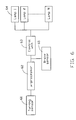
- Fig. 2 is a block diagram showing a vehicular turning indicator according to an embodiment of the present invention.
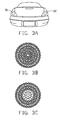
- Fig. 3A is schematic diagram exemplifying the arrangement of the vehicular turning indicator of Fig. 2 on the vehicle body;
- Figs. 3B and 3C are schematic diagram exemplifying two constant patterns appearing when the indicator light switch of Fig. 2 is enabled;
- Figs. 4A and 4B are schematic diagram exemplifying two variable patterns appearing when the turning sensor of Fig. 2 detects the turning action of the vehicle;
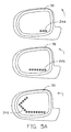
- Fig. 5A is a schematic diagram exemplifying the arrangement of the vehicular turning indicator of Fig. 2 in the external rearview mirror module;
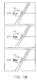
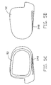
- Figs. 5B ⁇ 5D are schematic diagrams exemplifying the arrangement of the vehicular turning indicator of Fig. 2 on the housing of the external rearview mirror module;
- Fig. 5E is a schematic diagram exemplifying the arrangement of the vehicular turning indicator of Fig. 2 in the internal rearview mirror module;
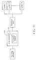
- Fig. 6 is a block diagram showing a vehicular turning indicator according to another embodiment of the present invention.
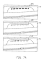
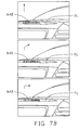
- Figs. 7A ⁇ 7C are schematic diagrams exemplifying the integration of the vehicular turning indicator of Fig. 6 with the auxiliary brake lamps;
- Fig. 8 is a schematic diagram exemplifying the arrangement of the vehicular turning indicator of Fig. 6 in the auxiliary brake lamp module;
- Fig. 9 is a block diagram showing a vehicular turning indicator according to another embodiment of the present invention.
- Fig. 10 is a schematic diagram exemplifying the arrangement of the vehicular turning indicator of Fig. 9 in the head-up display module and visible on the windscreen of the vehicle;
- Fig. 11 is a block diagram showing a vehicular turning indicator according to another embodiment of the present invention.
- Fig. 12A is an example of the lookup table for use in the vehicular turning indicator of Fig. 11;
- Fig. 12B is an operational example of the vehicular turning indicator of Fig. 11 on the basis of the lookup table of Fig. 12A;
- Fig. 13 is a block diagram showing a vehicular turning indicator according to another embodiment of the present invention.
- Figs. 14A ⁇ 14C are schematic diagrams exemplifying the arrangement of the vehicular turning indicator of Fig. 13 on various positions of the vehicle;
- Figs. 15A ⁇ 15D are schematic diagrams exemplifying various lamp patterns shown by the vehicular turning indicator of Fig. 13;
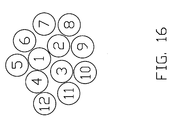
- Fig. 16 is a schematic diagram exemplifying another lamp pattern shown by the vehicular turning indicator of Fig. 13.
- the vehicular turning indicator for automatically showing a turning direction and a turning degree of a vehicle can be implemented by or incorporated into currently existent vehicular lamps such as an indicator light, a brake light or a head-up display according to one aspect of the present invention.
- Fig. 2 shows a first embodiment of the vehicular turning indicator according to the present invention.
- the vehicular turning indicator is implemented by an indicator light.
- the vehicular turning indicator performs dual functions, one for direction indicator light and the other for dynamic turning indication light.
- the vehicular turning indicator is enabled in a constant pattern to show that the vehicle is going to take a turn in response to an ON state of an indicator light switch.
- the vehicular turning indicator is enabled in a variable pattern to show that the vehicle is now turning and show the turning degree of the vehicle as well.
- the vehicular turning indicator shown in Fig. 2 includes a turning sensor 21, a micro-processor 22, a control unit 23 and a series of lightening units known together as lamps 24 intercommunicated as shown.
- the control unit 23 is further in communication with the indicator light switch 25.
- the connecting lines among these devices as shown do not indicate the connection of these devices essentially by wires or cables. Alternatively, they can communicate with one another via a vehicular digital bus such as a controller area network (CAN) or vehicle area network (VAN) bus.
- the sensor 21 is mounted to a steering wheel (not shown) of the vehicle for detecting a rotation degree of the steering wheel, and outputting a digital signal indicative of the turning direction and the turning angle according to the rotation degree of the steering wheel.
- a commercial sensor such as a 9850 Gen II Series sensor or an NCAPS® Thin Profile sensor commercially available from BEI Technologies Inc. (California, USA), can be applied hereto to achieve the above purpose.
- a control signal is asserted to turn on a selected portion of the lamps 24 associated with the right side to constitute a constant pattern.
- all the lamps 24 associated with the right side are turned on or just some constant lamps are turned on.
- the constant pattern for either of the vehicular turning indicators 31 and 32 can be exemplified as that shown in Fig. 3B or 3C.
- each small circle represents a single lamp, and the circles with and without hatch lines indicate brightening and non-brightening lamps, respectively.
- the micro-processor 22 determines how many and what ones of the lamps at the right side should be turned on in response to the digital signal in connection with the turning direction and turning degree. Then, the control unit 23 variably turns on the lamps of the right vehicular turning indicators 32 to show the desired pattern determined by the micro-processor 22.
- Fig. 4A or 4B schematically exemplifies the pattern-changing process of the right vehicular turning indicator 32 of this embodiment.
- no lamp is turned on.
- a small portion 241 of lamps of the vehicular turning indicator 32 brighten to warn others.
- all the lamps 243 will be turned on to exhibit prominent warning effect. By this way, other drivers can timely understand what direction the present vehicle is moving toward.
- the indicator lights are disposed at various positions on the car in addition to the front and rear sides of the car.
- rearview mirror modules are popular places for mounting indicator lights. Therefore, the vehicular turning indicator can also be mounted at these places to perform both direction and turning degree indication functions, as mentioned above.
- Fig. 5A shows an example in connection with the incorporation of a vehicular turning indicator into an exterior rearview mirror module.
- the lamps in this example are mounted inside the rearview mirror module 50 and visible through the mirror.
- a small portion 244 of lamps brighten.
- a larger portion 245 of lamps brighten to indicate a left turn with a larger degree.
- all the lamps 246 will be turned on to exhibit prominent warning effect.
- the lamps 247 mounted onto the housing of the exterior rearview mirror module 51 and facing the vehicular forwarding direction selectively brighten portion by portion to show the degree of right turn, as shown in Fig. 5B.
- the lamps 248 can also be arranged under the exterior rearview mirror module 52, as shown in Figs. 5C and 5D, so that both the forward-coming and the rearward-coming drivers can see the lamps. They are selectively turned on to brighten portion by portion to show the degree of right turn in a similar way mentioned above.
- both the right and left vehicular turning indicators 33 and 34 according to the present invention can be incorporated into the single interior rearview mirror module 53, as shown in Fig. 5E. For example, when the vehicle is making left turn, the driver can confirm what turning degree is achieved by viewing the brightening lamps on the interior rearview mirror 53.
- each single lamp of the vehicular turning indicator can be a filament lamp or a bulb with an orange cover, an orange light emitting diode (LED), an electro luminescence (EL) segment, a fluorescent tube or any other suitable lamp capable of brightening orange light.
- each lamp can be a bi-color or multi-color lamp which can brighten orange light and another color of light.
- the control unit 23 (Fig. 2) controls selected lamps to brighten orange light to constitute the constant pattern when the indicator light switch 25 is switched on, and brighten another color of light, e.g. blue light, to show the turning degree.
- the above-described vehicular turning indicator incorporated into a rearview mirror module does not have to exhibit the function of direction indicator light.
- the control unit can be exempted from connecting to the indicator light switch, and the vehicular turning indicator simply performs the function of automatically showing the turning degree of the vehicle.
- a brake light In addition to indicator light, another currently existent vehicular light into which the vehicular turning indicator for automatically showing a turning direction and a turning degree of a vehicle can be incorporated is a brake light.
- Fig. 6 shows a second embodiment of the vehicular turning indicator according to the present invention.
- the vehicular turning indicator is implemented by a brake light.
- the vehicular turning indicator performs dual functions, one for brake indication and the other for dynamic turning indication.
- the vehicular turning indicator is enabled in a constant pattern to show that the vehicle is braking.
- the vehicular turning indicator is enabled in a variable pattern to show that the vehicle is now turning and show the turning degree of the vehicle as well.
- the vehicular turning indicator shown in Fig. 6 includes a turning sensor 61, a micro-processor 62, a control unit 63 and a series of lamps 64 intercommunicated as shown.
- the control unit 63 is further in communication with a brake sensor 65.
- the connecting lines among these devices as shown do not indicate the connection of these devices essentially by wires or cables. Alternatively, they can communicate with one another via a vehicular digital bus such as a controller area network (CAN) or vehicle area network (VAN) bus.
- CAN controller area network
- VAN vehicle area network
- the sensor 61 can be a 9850 Gen II Series sensor or an NCAPS® Thin Profile sensor, which is mounted to a steering wheel (not shown) of the vehicle for detecting a rotation degree of the steering wheel, and outputting a digital signal indicative of the turning direction and the turning angle according to the rotation degree of the steering wheel.
- a control signal is asserted to turn on a selected portion of the lamps 64 associated with the right side to constitute a constant pattern. For example, all the lamps 64 are turned on or just some constant lamps are turned on.
- the schematic diagrams of Figs. 3A ⁇ 3C and 4 can be used herein for illustrating the dual-functional vehicular turning indicator except that the lights serve as brake lights in stead of indicator lights. As shown in Fig. 3A, the vehicular turning indicators 31 and 32 are disposed at right and left rear corners of the body of the vehicle.
- the brake sensor 65 informs the control unit 63 of the brake operation so that the constant pattern is shown for each of the vehicular turning indicators 31 and 32.
- the constant pattern can be exemplified as that shown in Fig. 3B or 3C.
- the micro-processor 62 determines how many and what ones of the lamps at the right side should be turned on in response to the digital signal in connection with the turning direction and turning degree. Then, the control unit 63 variably turns on the lamps of the right vehicular turning indicators 32 to show the desired pattern determined by the micro-processor 62.
- the pattern-changing process of the right vehicular turning indicator 32 is shown with reference to Fig. 4.
- each single lamp of the vehicular turning indicator can be a filament lamp or a bulb with a red cover, a red light emitting diode (LED), an electro luminescence (EL) segment, a fluorescent tube, or any other suitable lamp capable of brightening red light.
- each lamp can be a bi-color or multi-color lamp which can brighten red light and another color of light.
- the control unit 63 (Fig. 6) controls selected lamps to brighten red light to constitute the constant pattern when the brake sensor 65 detects a brake operation, and brighten another color of light, e.g. orange light, to show the turning degree.
- auxiliary brake lights 641 are disposed near the rear windscreens 70 inside the cars, as shown in Fig. 7A, and some auxiliary brake lights 642 are arranged on rear spoilers of the cars, either on the rear wings 71 as shown in Fig. 7B or on the up door spoilers 72 as shown in Fig. 7C.
- Fig. 7A shows an example in connection with the incorporation of a vehicular turning indicator into a first kind of auxiliary brake light module.
- Fig. 7C shows the situation similar to Fig. 7B except that the lamps are mounted on the up door spoiler module 72.
- the lamps of the vehicular turning indicator can also be additionally provided and incorporated into the auxiliary brake light.
- the lamps 643, for example, can be arranged below (or above) the lamps of the auxiliary brake light 73, as shown in Fig. 8. By this way, both the braking indication and the turning degree indication can be performed at the same time.
- Fig. 9 shows a third embodiment of the vehicular turning indicator according to the present invention.
- the vehicular turning indicator is incorporated into a head-up display, which is generally projected on the front windscreen of the vehicle.
- the vehicular turning indicator shown in Fig. 9 includes a turning sensor 91, a micro-processor 92, a control unit 93 and a series of light-emitting elements 94 intercommunicated as shown.
- the control unit 93 is optionally in communication with an information input device 95. It is to be noted that the connecting lines among these devices as shown do not indicate the connection of these devices essentially by wires or cables.
- the senor 91 can be a 9850 Gen II Series sensor or an NCAPS® Thin Profile sensor, which is mounted to a steering wheel (not shown) of the vehicle for detecting a rotation degree of the steering wheel, and outputting a digital signal indicative of the turning direction and the turning angle according to the rotation degree of the steering wheel.
- the light-emitting elements 94 are parts of a head-up display, and vary with the kinds of head-up displays.
- the light-emitting elements 94 will be fluorescent tubes when the head-up display is a vacuum fluorescent display (VFD).
- the head-up display can also be a digital light processor (DLP) display, a liquid crystal on silicon (LCOS) display, a thin film transistor liquid crystal display (TFTLCD) or a transparent liquid crystal display (transparent LCD), and has corresponding light-emitting elements 94. If the light-emitting elements 94 are additionally provided in the head-up display, and specifically used for showing the turning degree of the vehicle, the control unit 93 does not have to communicate with the information input device.
- DLP digital light processor
- LCOS liquid crystal on silicon
- TFTLCD thin film transistor liquid crystal display
- transparent LCD transparent LCD
- the control unit 93 When the control unit 93 receives a digital signal from the sensor 91 to indicate a turning-right operation of the vehicle, the micro-processor 92 determines how many and what ones of the light-emitting elements 94 at the right side should be actuated to brighten in response to the digital signal in connection with the turning direction and turning degree. Then, the control unit 93 variably actuates the light-emitting elements 94 of the vehicular turning indicators to show the desired pattern determined by the micro-processor 92, as exemplified in Fig. 10. On the display, the turning degree, e.g. 60°, is preferably simultaneously shown.
- the light-emitting elements 94 can be parts of the existent light-emitting elements.
- the control unit 93 is further in communication with the information input device 95.
- the control unit 93 controls the light-emitting elements 94 to cooperate with other light-emitting elements to show the information.
- the light-emitting elements 94 are used to show the turning degree as described above.
- the microprocessor determines how many and what ones of the lamps should be turned on according to a turning direction, a turning angle and a speed of the vehicle. It is assumed that a first pattern is shown at a first speed, and a second pattern is shown at a second speed. If the turning direction and the turning angle are the same and the first speed is higher than the second speed, then the first pattern consists of more brightening lamps than the second pattern does.
- a lookup table 111 is built in the microprocessor 112, as shown in Fig. 11, for realizing how many and what ones of the lamps should be turned on.
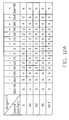
- the table shown in Fig. 12A illustrates a simplified lookup table, in which only the number of the lamps to be turned on is illustrated.
- the lamps 641 as shown in Fig. 7A are used for describing the lookup table.
- the lookup table of Fig. 12A when the vehicle is moving at a constant speed, the larger degrees of a turn, the larger number of turned-on lamps. For example, when the velocity is 60 km/hr, two lamps at the right side are turned on for a 5-degree right turn (+5°), three lamps at the right side are turned on for a 15-degree right turn (+15°), and five lamps at the right side are turned on for a 60-degree right turn (+60°).
- no lamp is brightening, i.e.
- more lamps are turned on for higher speed, as indicated by the lookup table of Fig. 12A.
- the same number of lamps can be turned on for different speeds, but the brightening lamps are different.
- An example is shown in Fig. 12B.
- the end brightening lamp 121 is closer to the turning direction, i.e. right direction in this example.
- the luminance of the brightening lamps may vary with vehicle speed, i.e. the lamps are brighter for higher speed, in order to enhance the warning effect.
- the above method for determining the number of brightening lamps depending on both of the turning degree and speed of a vehicle can be applied to any of the above embodiments by providing proper lookup tables.
- the lookup tables are designed on the basis of the turning angles, velocities and total numbers of turning indicator lamps.
- the vehicular turning indicator can be additionally and independently designed instead of being implemented by or incorporated into currently existent vehicular lamps such as an indicator light, a brake light or a head-up display.
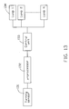
- the vehicular turning indicator includes a turning sensor 131, a micro-processor 132, a control unit 133 and a series of lamps 134 intercommunicated as shown in Fig. 13.
- the connecting lines among these devices as shown do not indicate the connection of these devices essentially by wires or cables.
- they can communicate with one another via a vehicular digital bus such as a controller area network (CAN) or vehicle area network (VAN) bus.
- CAN controller area network
- VAN vehicle area network
- the sensor 131 is mounted to a steering wheel (not shown) of the vehicle for detecting a rotation degree of the steering wheel, and outputting a digital signal indicative of the turning direction and the turning angle according to the rotation degree of the steering wheel.
- a commercial sensor such as a 9850 Gen II Series sensor or an NCAPS® Thin Profile sensor commercially available from BEI Technologies Inc. (California, USA), can be applied hereto to achieve the above purpose.
- the micro-processor 132 determines how many and what ones of the lamps at the right side should be turned on in response to the digital signal in connection with the turning direction, turning degree and preferably speed of the vehicle. Then, the control unit 133 variably turns on the lamps of the right vehicular turning indicators to show the desired pattern determined by the micro-processor 132.
- the lamps 134 can be arranged on the body of the vehicle under a lamp assembly 135 comprising an indicator light, a backup light and a brake light, as shown in Fig. 14A.
- the lamps 136 are arranged on the body of the vehicle between the trunk door 137 and the rear bumper 138, as shown in Fig. 14B.
- the lamps 136 consist of more than one color to distinguish different levels of turn so as to make the turning indication even prominent. For example, for the right portion of lamps in connection with the right turn indication, the left 2/3 portion 1361 of lamps brighten orange light and the right 1/3 portion 1362 of lamps brighten red light to inform other drivers of a sharp turn.
- the lamps can be mounted to any other suitable place as long as they can hold attraction from other drivers.
- the lamps can also be arranged on the body of the vehicle between the door of the engine room 140 and the front bumper 141 and/or arranged under the headlight lamps 142, as shown in Fig. 14C.
- the lamps may emit different colors of light for different functions.
- the color of light emitted in response to the operation of an indicator light switch or a brake operation can be different from that emitted in response to the turning angle.
- the colors of light emitted in response to different turning angles can be different as described above with reference to Fig. 14B.
- the colors of light may vary with turning angles in a manner as shown in Fig. 14C.
- the lamps 139 are used to show the brake operation, as in Case I
- the color of light is red.
- the lamps 139 are used to show the small degree of turning operation
- the color of light is yellow, as in Case II.
- the lamps 139 are used to show the large degree of turning operation, the color of light becomes red again, as in Case III.
- the luminance of the light can also vary with the turning degree and/or speed of the vehicle.
- a plurality of patterns can be sequentially shown for a specific turning direction and a specific turning angle.
- the lamps of any of the above embodiments can be made to sequentially twinkle.
- the transformation of the plurality of patterns or the twinkling action of the lamps preferably follows a predetermined rule. It is assumed that the vehicle is making a right turn at an angle of 60 degrees under a velocity of 60 km/hr. According to the lookup table of Fig. 12, five lamps at the right side should be turned on. In this embodiment, the five lamps sequentially twinkle instead of staying unchanged.
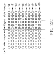
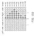
- Figs. 15A ⁇ 15D illustrate four examples of the sequentially twinkling action under the maximum number determined according to the turning direction, turning degree and/or vehicular speed.
- the maximum number of the lamps to brighten is five when the vehicle is making a right turn at an angle of 60 degrees under a velocity of 60 km/hr.
- five lamps are possibly brightening, and each of the five lamps twinkles, i.e. brightens and then darkens, according to a predetermined manner as shown.
- the embodiment of Fig. 15A only the leftmost one lamp is brightening at the time point t1. Then, the leftmost two lamps are brightening at the time point t2.
- one rightward lamp is additionally brightening at a time as time goes by.
- the leftmost two lamps brighten again.
- the maximum number of lamps i.e. five lamps, are brightening at first. Then, the lamps darken one by one from left to right. When the right-side lamp darkens, the left-side lamp re-illuminates.
- the embodiment of Fig. 15D is similar to that of Fig. 15A from the time point t1 to the time point t5. At the time point t6, the rightmost one among the five lamps darkens. Likewise, one leftward lamp is additionally darkening at a time as time goes by. The above procedures as executed from t1 to t8 start over when only one lamp is left brightening.
- the twinkle rate is up to a high rate and preferably depends on the speed of the vehicle so that people will see the lamps running, thereby holding people's attraction.
- a linear lamp shape is exemplified for illustrating the twinkle action of the lamps, the twinkle principal may be applied to various lamp shapes by those skilled in the art.
- the brightening modes shown in Figs. 15A ⁇ 15D can also be applied here.
- the numbers labeled inside the lamps indicate the brightening sequence of the lamps.
- the present invention provides various vehicular turning indicators capable of automatically show the turning degree of a vehicle.
- the vehicular turning indicator can be implemented by currently existent vehicular lamps, be incorporated into an existent vehicular accessory, utilize special flashing effects to make the turning indication prominent, allow the driver himself to see the turning indication, and/or operate depending on the speed of the vehicle.
- the present vehicular turning indicators the movement of the vehicle can be monitored so as to enhance the driving safety.
Landscapes
- Engineering & Computer Science (AREA)
- Mechanical Engineering (AREA)
- Lighting Device Outwards From Vehicle And Optical Signal (AREA)
Applications Claiming Priority (2)
| Application Number | Priority Date | Filing Date | Title |
|---|---|---|---|
| US10/653,610 US7002458B2 (en) | 2003-09-02 | 2003-09-02 | Vehicular turning indicator |
| US653610 | 2003-09-02 |
Publications (1)
| Publication Number | Publication Date |
|---|---|
| EP1512579A2 true EP1512579A2 (de) | 2005-03-09 |
Family
ID=34136654
Family Applications (1)
| Application Number | Title | Priority Date | Filing Date |
|---|---|---|---|
| EP04020394A Withdrawn EP1512579A2 (de) | 2003-09-02 | 2004-08-27 | Blinker für Fahrzeuge |
Country Status (5)
| Country | Link |
|---|---|
| US (1) | US7002458B2 (de) |
| EP (1) | EP1512579A2 (de) |
| JP (1) | JP2005075349A (de) |
| KR (1) | KR20050024189A (de) |
| TW (1) | TW200510200A (de) |
Cited By (7)
| Publication number | Priority date | Publication date | Assignee | Title |
|---|---|---|---|---|
| EP1818214A1 (de) * | 2006-02-14 | 2007-08-15 | Schefenacker Vision Systems Germany GmbH | Leuchte, insbesondere Heckleuchte eines Fahrzeuges, vorzugsweise eines Kraftfahrzeuges |
| EP1884407A1 (de) * | 2006-07-28 | 2008-02-06 | Georg Geiger | Geschwindigkeitsaußenanzeige für Kfz |
| DE102009010298A1 (de) * | 2009-02-24 | 2009-10-01 | Daimler Ag | Fahrzeugscheinwerfer |
| DE102011119230A1 (de) * | 2011-11-23 | 2013-05-23 | Audi Ag | Kraftwagen-Blinkleuchte und Verfahren zum Betreiben einer Blinkleuchte |
| EP2567866A3 (de) * | 2011-09-07 | 2014-12-31 | Audi Ag | Verfahren zum Betreiben eines Scheinwerfers eines Kraftfahrzeugs |
| CN104527510A (zh) * | 2014-12-19 | 2015-04-22 | 奇瑞汽车股份有限公司 | 转向辅助系统及其控制方法 |
| WO2016011838A1 (zh) * | 2014-07-25 | 2016-01-28 | 北汽福田汽车股份有限公司 | 车辆转向的提示方法、系统及具有该系统的汽车 |
Families Citing this family (64)
| Publication number | Priority date | Publication date | Assignee | Title |
|---|---|---|---|---|
| DE10324812A1 (de) * | 2003-06-02 | 2004-12-23 | Robert Bosch Gmbh | Anzeigeanordnung für ein Kraftfahrzeug und Verfahren zur Ausgabe von Fahrerinformationen, insbesondere für eine Einparkhilfe |
| US7119672B2 (en) * | 2004-03-05 | 2006-10-10 | Ramesh Subbaraman | Dynamic vehicle signaling device and system |
| US7482916B2 (en) | 2004-03-15 | 2009-01-27 | Anita Au | Automatic signaling systems for vehicles |
| CA2573778A1 (en) * | 2004-07-13 | 2006-02-16 | Sparks, Terry | Transmitter apparatus and system for remote signaling |
| US20060038671A1 (en) * | 2004-08-18 | 2006-02-23 | Shiang-Sheng Cheng | Automobile and motorcycle automatic direction indicating device |
| JP4587301B2 (ja) * | 2005-02-23 | 2010-11-24 | 本田技研工業株式会社 | 車両用被認識装置 |
| JP4580288B2 (ja) * | 2005-06-28 | 2010-11-10 | 本田技研工業株式会社 | 運転支援自動車 |
| US7425893B2 (en) * | 2005-06-29 | 2008-09-16 | Mathew Randolph Aron | Integrated motorcycle light frame and turn signal assembly |
| US20070080796A1 (en) * | 2005-10-12 | 2007-04-12 | Hung-Sheng Wang | Car lighting and alerting device |
| US9808023B2 (en) * | 2006-03-02 | 2017-11-07 | Kao Corporation | Process for producing purified tea extract |
| JP5334372B2 (ja) * | 2007-02-15 | 2013-11-06 | 株式会社小糸製作所 | 発光装置 |
| JP4540004B2 (ja) * | 2007-04-16 | 2010-09-08 | 庄吾 土田 | 変色可能式等ウインカーランプ |
| US7868555B2 (en) * | 2007-04-23 | 2011-01-11 | Timothy Patrick Peron | Enhanced vehicle side signal lighting system |
| US7791464B1 (en) | 2007-06-21 | 2010-09-07 | Jason Myron Giddings | Tractor-trailer rig deployable sign |
| US20090051522A1 (en) * | 2007-08-24 | 2009-02-26 | Mark Perkins | Led sequential lighting system for vehicles and method of use |
| US20090051523A1 (en) * | 2007-08-24 | 2009-02-26 | Mark Perkins | Led sequential lighting system for vehicles and method of use |
| CN101556012A (zh) * | 2008-04-08 | 2009-10-14 | 鸿富锦精密工业(深圳)有限公司 | 汽车尾灯 |
| WO2010045908A1 (de) * | 2008-10-22 | 2010-04-29 | Continental Teves Ag & Co. Ohg | Verfahren und vorrichtung zur automatischen fahrtrichtungsanzeige |
| WO2011113158A1 (en) * | 2010-03-15 | 2011-09-22 | Smithson Bradley D | Multifunction indicator |
| US8547219B2 (en) * | 2010-06-11 | 2013-10-01 | Anthony J. KISIEL | Automotive brake light with graduated display |
| KR101219928B1 (ko) * | 2010-09-10 | 2013-01-08 | 기아자동차주식회사 | 차량의 전조등 제어 시스템 |
| US8513955B2 (en) * | 2010-09-28 | 2013-08-20 | Tyco Electronics Corporation | SSL budgeting and coding system for lighting assembly |
| TWM400964U (en) * | 2010-09-29 | 2011-04-01 | chang-sheng Liu | Light-emitting device for cars |
| US8934062B1 (en) * | 2010-12-17 | 2015-01-13 | Roger Bosarge | Digital vehicle display unit and remote |
| US8823265B2 (en) * | 2011-06-22 | 2014-09-02 | Osram Sylvania Inc. | Sequential vehicle signaling system and method |
| DE102011055598B4 (de) * | 2011-11-22 | 2023-09-28 | HELLA GmbH & Co. KGaA | Verfahren für die Regelung zumindest einer Lichtfunktion eines Scheinwerfers oder einer Leuchte eines Fahrzeugs |
| JP2013132998A (ja) * | 2011-12-26 | 2013-07-08 | Shogo Tsuchida | 変色可能式等ウインカーランプ第2章 |
| US8588997B2 (en) * | 2012-01-20 | 2013-11-19 | Custom Dynamics Llc | Devices and methods for controlling vehicle lights |
| JP5467617B2 (ja) * | 2012-02-27 | 2014-04-09 | 土田 庄吾 | 変色可能式等ウインカーランプ第2章 |
| US20140091921A1 (en) * | 2012-09-28 | 2014-04-03 | Pei-Hsun Cheng | Lighting Apparatus with Functions of Break Warning and Directional Indication |
| JP6163033B2 (ja) * | 2013-07-10 | 2017-07-12 | 矢崎総業株式会社 | ヘッドアップディスプレイ装置及び表示ユニット |
| JP6244135B2 (ja) * | 2013-08-09 | 2017-12-06 | 矢崎総業株式会社 | メータ |
| JP6275968B2 (ja) * | 2013-08-09 | 2018-02-07 | 矢崎総業株式会社 | ランプユニット制御システム |
| JP6275969B2 (ja) * | 2013-08-09 | 2018-02-07 | 矢崎総業株式会社 | ランプユニット制御装置 |
| US8939706B1 (en) | 2014-02-25 | 2015-01-27 | Siemens Energy, Inc. | Turbine abradable layer with progressive wear zone having a frangible or pixelated nib surface |
| JP6243288B2 (ja) * | 2014-04-25 | 2017-12-06 | サカエ理研工業株式会社 | 車両用発光装置 |
| CN104015801A (zh) * | 2014-06-17 | 2014-09-03 | 无锡市崇安区科技创业服务中心 | 一种车辆转弯角度辅助提示装置 |
| US9187031B1 (en) * | 2014-06-24 | 2015-11-17 | Gm Global Technology Operations | Tail light assembly for a vehicle |
| WO2016001936A2 (en) * | 2014-06-30 | 2016-01-07 | Rohit Singh | Direction signalling apparatus for motor vehicle |
| JP6687540B2 (ja) * | 2014-12-24 | 2020-04-22 | 株式会社小糸製作所 | 光源点灯回路、ターンシグナルランプ |
| CN107107818B (zh) * | 2014-12-26 | 2020-06-19 | 横滨橡胶株式会社 | 方向指示灯装置以及防撞系统 |
| KR102360144B1 (ko) * | 2014-12-30 | 2022-02-07 | 주식회사 엘엑스세미콘 | 리어 콤비네이션 램프 장치 |
| KR102311637B1 (ko) * | 2015-02-24 | 2021-10-12 | 현대모비스 주식회사 | 자동차 후미등 |
| US10112528B1 (en) * | 2015-07-28 | 2018-10-30 | Apple Inc. | Exterior lighting and warning system |
| US9566902B1 (en) | 2015-11-30 | 2017-02-14 | Custom Dynamics Llc | Control circuit for vehicle with composite brake/turn lights |
| TWI569235B (zh) | 2015-12-09 | 2017-02-01 | 財團法人工業技術研究院 | 車輛轉向警示方法及車輛轉向警示裝置 |
| KR20170082670A (ko) * | 2016-01-06 | 2017-07-17 | 엘지전자 주식회사 | 차량용 램프 및 이를 포함하는 차량 |
| US9896020B2 (en) | 2016-05-23 | 2018-02-20 | Ford Global Technologies, Llc | Vehicle lighting assembly |
| US9951921B2 (en) * | 2016-08-26 | 2018-04-24 | Se-Ho OH | Vehicle taillight system |
| JP6722355B2 (ja) | 2017-03-07 | 2020-07-15 | コンチネンタル オートモーティヴ ゲゼルシャフト ミット ベシュレンクテル ハフツングContinental Automotive GmbH | ステアリングホイールの手動操作を検出するための装置及び方法 |
| US10569701B2 (en) * | 2017-03-31 | 2020-02-25 | Valeo North America, Inc. | Systems and methodologies for controlling a vehicle light |
| US10118542B1 (en) * | 2017-05-03 | 2018-11-06 | Ford Global Technologies, Llc | Vehicle side lighting arrangement |
| US10378720B2 (en) | 2017-12-08 | 2019-08-13 | Aubrey Shane Ashley | Safety lighting system |
| US11104270B1 (en) * | 2018-06-06 | 2021-08-31 | Rodney Timms | Warning light system for truck safety |
| JP2020069919A (ja) * | 2018-10-31 | 2020-05-07 | 市光工業株式会社 | 車両用灯具 |
| JP7206884B2 (ja) * | 2018-12-17 | 2023-01-18 | トヨタ自動車株式会社 | 特殊転舵装置を備えた車両 |
| JP7515244B2 (ja) * | 2019-09-30 | 2024-07-12 | スタンレー電気株式会社 | 車両用灯具の点灯制御装置及び点灯制御方法、車両用灯具システム |
| JP7345339B2 (ja) * | 2019-09-30 | 2023-09-15 | スタンレー電気株式会社 | 車両用灯具の点灯制御装置及び点灯制御方法、車両用灯具システム |
| JP7369584B2 (ja) * | 2019-10-03 | 2023-10-26 | スタンレー電気株式会社 | 車両用灯具の点灯制御装置及び点灯制御方法、車両用灯具システム |
| JP2021059288A (ja) * | 2019-10-09 | 2021-04-15 | スタンレー電気株式会社 | 車両用灯具の点灯制御装置及び点灯制御方法、車両用灯具システム |
| KR102262141B1 (ko) * | 2019-11-04 | 2021-06-09 | 현대자동차주식회사 | 차량의 서라운딩 램프 시스템 제어방법 |
| CN114043930B (zh) * | 2021-11-19 | 2023-12-15 | 东风柳州汽车有限公司 | 一种汽车灯光系统转向控制方法、车辆控制装置以及汽车 |
| JP7834014B2 (ja) * | 2022-12-28 | 2026-03-23 | ソニー・ホンダモビリティ株式会社 | モビリティ外部ディスプレイ構造 |
| CN119099474A (zh) * | 2023-06-09 | 2024-12-10 | 长城汽车股份有限公司 | 提醒方法、提醒装置、车辆以及计算机可读存储介质 |
Family Cites Families (7)
| Publication number | Priority date | Publication date | Assignee | Title |
|---|---|---|---|---|
| JPH01197141A (ja) * | 1988-02-02 | 1989-08-08 | Stanley Electric Co Ltd | 自動車用リアコンビネーションランプ |
| US5157382A (en) * | 1990-10-18 | 1992-10-20 | Whelen Technologies, Inc. | Directional information conveying method and apparatus |
| JPH04104745U (ja) * | 1991-02-21 | 1992-09-09 | 泰 上野 | 運転状況表示器付きバツクミラー |
| US5712618A (en) * | 1995-08-29 | 1998-01-27 | Mckenna; Michael R. | Method and apparatus for an automatic signaling device |
| US5673019A (en) * | 1996-05-14 | 1997-09-30 | Dantoni; Joseph L. | Automatic turn signal and safety device |
| US6055539A (en) * | 1997-06-27 | 2000-04-25 | International Business Machines Corporation | Method to reduce I/O for hierarchical data partitioning methods |
| FR2815311B1 (fr) * | 2000-10-17 | 2003-01-03 | Peugeot Citroen Automobiles Sa | Procede d'indication du changement de direction d'un vehicule automobile et dispositif de mise en oeuvre du procede |
-
2003
- 2003-09-02 US US10/653,610 patent/US7002458B2/en not_active Expired - Fee Related
-
2004
- 2004-08-27 EP EP04020394A patent/EP1512579A2/de not_active Withdrawn
- 2004-08-31 KR KR1020040068833A patent/KR20050024189A/ko not_active Withdrawn
- 2004-09-01 TW TW093126336A patent/TW200510200A/zh unknown
- 2004-09-01 JP JP2004254516A patent/JP2005075349A/ja not_active Withdrawn
Cited By (9)
| Publication number | Priority date | Publication date | Assignee | Title |
|---|---|---|---|---|
| EP1818214A1 (de) * | 2006-02-14 | 2007-08-15 | Schefenacker Vision Systems Germany GmbH | Leuchte, insbesondere Heckleuchte eines Fahrzeuges, vorzugsweise eines Kraftfahrzeuges |
| EP1884407A1 (de) * | 2006-07-28 | 2008-02-06 | Georg Geiger | Geschwindigkeitsaußenanzeige für Kfz |
| DE102009010298A1 (de) * | 2009-02-24 | 2009-10-01 | Daimler Ag | Fahrzeugscheinwerfer |
| EP2567866A3 (de) * | 2011-09-07 | 2014-12-31 | Audi Ag | Verfahren zum Betreiben eines Scheinwerfers eines Kraftfahrzeugs |
| US9162610B2 (en) | 2011-09-07 | 2015-10-20 | Audi Ag | Method for operating a headlight of a motor vehicle |
| DE102011119230A1 (de) * | 2011-11-23 | 2013-05-23 | Audi Ag | Kraftwagen-Blinkleuchte und Verfahren zum Betreiben einer Blinkleuchte |
| DE102011119230B4 (de) * | 2011-11-23 | 2013-07-11 | Audi Ag | Kraftwagen-Blinkleuchte und Verfahren zum Betreiben einer Blinkleuchte |
| WO2016011838A1 (zh) * | 2014-07-25 | 2016-01-28 | 北汽福田汽车股份有限公司 | 车辆转向的提示方法、系统及具有该系统的汽车 |
| CN104527510A (zh) * | 2014-12-19 | 2015-04-22 | 奇瑞汽车股份有限公司 | 转向辅助系统及其控制方法 |
Also Published As
| Publication number | Publication date |
|---|---|
| US20050062597A1 (en) | 2005-03-24 |
| JP2005075349A (ja) | 2005-03-24 |
| TW200510200A (en) | 2005-03-16 |
| KR20050024189A (ko) | 2005-03-10 |
| US7002458B2 (en) | 2006-02-21 |
Similar Documents
| Publication | Publication Date | Title |
|---|---|---|
| US7002458B2 (en) | Vehicular turning indicator | |
| US20050134447A1 (en) | Automobile indicator | |
| US7710243B2 (en) | Driver-assistance vehicle | |
| US9802532B2 (en) | System for detecting surrounding conditions of moving body | |
| US20050099287A1 (en) | Indicator system for vehicles | |
| US20160318440A1 (en) | Printed led exterior mirror indicators | |
| EP3342643B1 (de) | Aussenrückblickvorrichtung mit beleuchtungsfunktionen | |
| US6952162B2 (en) | Multidirectional cluster lights for motor vehicles | |
| CN210881873U (zh) | 用于机动车辆的照明系统 | |
| CN1166524C (zh) | 多功能安全警示器 | |
| JP2002257236A (ja) | シフト装置 | |
| US4734697A (en) | Motor vehicle tail light assembly with dimmer controller | |
| CN111976589A (zh) | 一种汽车显示系统及汽车尾灯系统 | |
| CN1743204A (zh) | 汽车转向指示器 | |
| US20090109014A1 (en) | System and method for signaling personal messages by a driver of a motor vehicle | |
| JP2013184521A (ja) | 車輌用灯火装置およびその制御方法 | |
| CN102271964A (zh) | 显示装置 | |
| CN116080521B (zh) | 一种变道提醒系统及方法 | |
| USRE35686E (en) | Motor vehicle tail light assembly with dimmer controller | |
| JP2001347886A (ja) | 車両用led一体型リアランプ | |
| US20060192665A1 (en) | System for improving the visibility of a vehicle during reduced visibility conditions | |
| WO2007138713A1 (ja) | 分割点灯動作式テールランプ | |
| JP2002274216A (ja) | 車両用表示装置 | |
| US20040145901A1 (en) | Vehicle rearview mirror assembly with color changing legs | |
| CN1799902A (zh) | 车辆指示灯系统 |
Legal Events
| Date | Code | Title | Description |
|---|---|---|---|
| PUAI | Public reference made under article 153(3) epc to a published international application that has entered the european phase |
Free format text: ORIGINAL CODE: 0009012 |
|
| AK | Designated contracting states |
Kind code of ref document: A2 Designated state(s): AT BE BG CH CY CZ DE DK EE ES FI FR GB GR HU IE IT LI LU MC NL PL PT RO SE SI SK TR |
|
| AX | Request for extension of the european patent |
Extension state: AL HR LT LV MK |
|
| RAP1 | Party data changed (applicant data changed or rights of an application transferred) |
Owner name: EXON SCIENCE INC. |
|
| RIN1 | Information on inventor provided before grant (corrected) |
Inventor name: SU, WEN-WEI |
|
| STAA | Information on the status of an ep patent application or granted ep patent |
Free format text: STATUS: THE APPLICATION HAS BEEN WITHDRAWN |
|
| 18W | Application withdrawn |
Effective date: 20060308 |