EP1414145A1 - Appareil de commande d'entrainement de moteur - Google Patents
Appareil de commande d'entrainement de moteur Download PDFInfo
- Publication number
- EP1414145A1 EP1414145A1 EP02755717A EP02755717A EP1414145A1 EP 1414145 A1 EP1414145 A1 EP 1414145A1 EP 02755717 A EP02755717 A EP 02755717A EP 02755717 A EP02755717 A EP 02755717A EP 1414145 A1 EP1414145 A1 EP 1414145A1
- Authority
- EP
- European Patent Office
- Prior art keywords
- inverter
- motor
- voltage
- converter
- input voltage
- Prior art date
- Legal status (The legal status is an assumption and is not a legal conclusion. Google has not performed a legal analysis and makes no representation as to the accuracy of the status listed.)
- Granted
Links
Images


Classifications
-
- H—ELECTRICITY
- H02—GENERATION; CONVERSION OR DISTRIBUTION OF ELECTRIC POWER
- H02M—APPARATUS FOR CONVERSION BETWEEN AC AND AC, BETWEEN AC AND DC, OR BETWEEN DC AND DC, AND FOR USE WITH MAINS OR SIMILAR POWER SUPPLY SYSTEMS; CONVERSION OF DC OR AC INPUT POWER INTO SURGE OUTPUT POWER; CONTROL OR REGULATION THEREOF
- H02M7/00—Conversion of ac power input into dc power output; Conversion of dc power input into ac power output
- H02M7/42—Conversion of dc power input into ac power output without possibility of reversal
- H02M7/44—Conversion of dc power input into ac power output without possibility of reversal by static converters
- H02M7/48—Conversion of dc power input into ac power output without possibility of reversal by static converters using discharge tubes with control electrode or semiconductor devices with control electrode
-
- B—PERFORMING OPERATIONS; TRANSPORTING
- B60—VEHICLES IN GENERAL
- B60L—PROPULSION OF ELECTRICALLY-PROPELLED VEHICLES; SUPPLYING ELECTRIC POWER FOR AUXILIARY EQUIPMENT OF ELECTRICALLY-PROPELLED VEHICLES; ELECTRODYNAMIC BRAKE SYSTEMS FOR VEHICLES IN GENERAL; MAGNETIC SUSPENSION OR LEVITATION FOR VEHICLES; MONITORING OPERATING VARIABLES OF ELECTRICALLY-PROPELLED VEHICLES; ELECTRIC SAFETY DEVICES FOR ELECTRICALLY-PROPELLED VEHICLES
- B60L50/00—Electric propulsion with power supplied within the vehicle
- B60L50/50—Electric propulsion with power supplied within the vehicle using propulsion power supplied by batteries or fuel cells
- B60L50/51—Electric propulsion with power supplied within the vehicle using propulsion power supplied by batteries or fuel cells characterised by AC-motors
-
- H—ELECTRICITY
- H02—GENERATION; CONVERSION OR DISTRIBUTION OF ELECTRIC POWER
- H02P—CONTROL OR REGULATION OF ELECTRIC MOTORS, ELECTRIC GENERATORS OR DYNAMO-ELECTRIC CONVERTERS; CONTROLLING TRANSFORMERS, REACTORS OR CHOKE COILS
- H02P27/00—Arrangements or methods for the control of AC motors characterised by the kind of supply voltage
- H02P27/04—Arrangements or methods for the control of AC motors characterised by the kind of supply voltage using variable-frequency supply voltage, e.g. inverter or converter supply voltage
- H02P27/06—Arrangements or methods for the control of AC motors characterised by the kind of supply voltage using variable-frequency supply voltage, e.g. inverter or converter supply voltage using dc to ac converters or inverters
- H02P27/08—Arrangements or methods for the control of AC motors characterised by the kind of supply voltage using variable-frequency supply voltage, e.g. inverter or converter supply voltage using dc to ac converters or inverters with pulse width modulation
- H02P27/14—Arrangements or methods for the control of AC motors characterised by the kind of supply voltage using variable-frequency supply voltage, e.g. inverter or converter supply voltage using dc to ac converters or inverters with pulse width modulation with three or more levels of voltage
-
- H—ELECTRICITY
- H02—GENERATION; CONVERSION OR DISTRIBUTION OF ELECTRIC POWER
- H02M—APPARATUS FOR CONVERSION BETWEEN AC AND AC, BETWEEN AC AND DC, OR BETWEEN DC AND DC, AND FOR USE WITH MAINS OR SIMILAR POWER SUPPLY SYSTEMS; CONVERSION OF DC OR AC INPUT POWER INTO SURGE OUTPUT POWER; CONTROL OR REGULATION THEREOF
- H02M1/00—Details of apparatus for conversion
- H02M1/0067—Converter structures employing plural converter units, other than for parallel operation of the units on a single load
- H02M1/007—Plural converter units in cascade
-
- H—ELECTRICITY
- H02—GENERATION; CONVERSION OR DISTRIBUTION OF ELECTRIC POWER
- H02P—CONTROL OR REGULATION OF ELECTRIC MOTORS, ELECTRIC GENERATORS OR DYNAMO-ELECTRIC CONVERTERS; CONTROLLING TRANSFORMERS, REACTORS OR CHOKE COILS
- H02P2201/00—Indexing scheme relating to controlling arrangements characterised by the converter used
- H02P2201/03—AC-DC converter stage controlled to provide a defined DC link voltage
-
- H—ELECTRICITY
- H02—GENERATION; CONVERSION OR DISTRIBUTION OF ELECTRIC POWER
- H02P—CONTROL OR REGULATION OF ELECTRIC MOTORS, ELECTRIC GENERATORS OR DYNAMO-ELECTRIC CONVERTERS; CONTROLLING TRANSFORMERS, REACTORS OR CHOKE COILS
- H02P2201/00—Indexing scheme relating to controlling arrangements characterised by the converter used
- H02P2201/07—DC-DC step-up or step-down converter inserted between the power supply and the inverter supplying the motor, e.g. to control voltage source fluctuations, to vary the motor speed
-
- Y—GENERAL TAGGING OF NEW TECHNOLOGICAL DEVELOPMENTS; GENERAL TAGGING OF CROSS-SECTIONAL TECHNOLOGIES SPANNING OVER SEVERAL SECTIONS OF THE IPC; TECHNICAL SUBJECTS COVERED BY FORMER USPC CROSS-REFERENCE ART COLLECTIONS [XRACs] AND DIGESTS
- Y02—TECHNOLOGIES OR APPLICATIONS FOR MITIGATION OR ADAPTATION AGAINST CLIMATE CHANGE
- Y02T—CLIMATE CHANGE MITIGATION TECHNOLOGIES RELATED TO TRANSPORTATION
- Y02T10/00—Road transport of goods or passengers
- Y02T10/60—Other road transportation technologies with climate change mitigation effect
- Y02T10/64—Electric machine technologies in electromobility
-
- Y—GENERAL TAGGING OF NEW TECHNOLOGICAL DEVELOPMENTS; GENERAL TAGGING OF CROSS-SECTIONAL TECHNOLOGIES SPANNING OVER SEVERAL SECTIONS OF THE IPC; TECHNICAL SUBJECTS COVERED BY FORMER USPC CROSS-REFERENCE ART COLLECTIONS [XRACs] AND DIGESTS
- Y02—TECHNOLOGIES OR APPLICATIONS FOR MITIGATION OR ADAPTATION AGAINST CLIMATE CHANGE
- Y02T—CLIMATE CHANGE MITIGATION TECHNOLOGIES RELATED TO TRANSPORTATION
- Y02T10/00—Road transport of goods or passengers
- Y02T10/60—Other road transportation technologies with climate change mitigation effect
- Y02T10/70—Energy storage systems for electromobility, e.g. batteries
Definitions
- the present invention relates to a motor drive controller for supplying output from a dc power source to a motor through an inverter, and controlling drive of the motor.
- a hybrid vehicle or an electric vehicle has a motor for traveling, and traveling is accomplished by driving this motor.
- a battery is therefore required to supply electrical power to the motor, and a high voltage battery of a few hundred volts is normally used in order to efficiently supply electrical power to a high output motor.
- various components (accessories) operated by electrical power are mounted in the vehicle, and a 12V battery (low voltage battery) is used as a battery for these accessories. High voltage output of the high voltage battery is then stepped down to 12V using a converter to charge the low voltage battery.
- a converter is arranged between a battery and an inverter and a boosted voltage is supplied to the inverter using the converter. It is therefore possible to apply a high voltage from the inverter to the motor, and it is possible to increase maximum torque in a high rotational speed range of the motor.
- This publication also proposes using a converter as a rectifier for when charging from the outside.
- the above publication therefore shows boosting of a battery voltage using a converter and supply of that boosted voltage to a motor.
- this publication simply discloses boosting a supply to a motor and does not consider control of the operation in boosting by the controller.
- the object of the present invention is to provide a motor drive controller that can optimize inverter input voltage in response to motor drive conditions.
- the present invention is a motor drive controller for supplying output of a dc power source to a motor through an inverter and controlling drive of a motor, comprising a converter for voltage converting output voltage from the dc power source for supply to the inverter, and a control section for controlling supply current to the motor through PWM control of the inverter, the converter comprising a reactor connected at one end to the dc power source and at least two switching elements, being an upper switching element connecting the other end of the reactor to a power source side of the inverter and a lower switching element connecting to an earth side of the inverter, wherein the control section calculates an inverter input voltage target value appropriate to efficiently drive a motor in response to rotational speed of the motor and a target output torque, and performs PWM control of the converter switching elements in order to achieve this input voltage target value.
- inverter input voltage above the battery voltage because of the inverter. Since motor output is a product of voltage applied to the motor and motor current, it is possible to reduce motor current for the same motor output by increasing the voltage applied to the motor. It is possible to reduce inverter current capacity by increasing the inverter input voltage, to therefore enable miniaturization and cost reduction of the inverter. Also, since output in a high rotational speed range of the motor is increased by increasing the voltage applied to the motor, this resultantly enables miniaturization and cost reduction of the motor.
- an optimum voltage to be applied to the motor at any given time is calculated based on the rotational speed of the motor and a target output torque (output torque command), and an inverter input voltage target value is determined based on this calculated optimum voltage.
- efficient drive of the motor is carried out by applying the optimum voltage based on running conditions of the motor at that time.
- the optimum voltage is calculated and this voltage controlled, it is possible to prevent deterioration in efficiency due to the voltage rising beyond what is necessary.
- the converter preferably has a three phase structure provided with three sets of the reactor and the two switching elements. With this structure, it is possible to smooth the output voltage to suppress the occurrence of ripple.
- the inverter input voltage target value is lower than the dc source voltage
- an input target voltage of the inverter to drive efficiently becomes smaller than the voltage of the dc power source.
- turning the upper switching element of the inverter on and turning the lower switching element off does not produce any switching loss at the same time as setting to the converter minimum drive voltage, which enables efficient drive.
- the converter prefferably has a full bridge configuration with both ends of a battery and one end of a reactor being connected through two switching elements. With this structure, it also becomes possible to step-down the dc power source output, and to always have the optimum inverter applied voltage.
- inverter input voltage to obtain the most efficient drive for respective motors will often differ.
- inverter input voltage is high, only switching loss is increased, but when the input voltage is low, motor current also increases and loss of both the motor and inverter increases. This means that efficiency is better with a high voltage. It is thus possible to raise overall efficiency by selecting the higher of the respective inverter input target voltages.
- control section When the calculated inverter input target voltage exceeds a specified upper limit value, the control section preferably sets the input target voltage to the upper limit value.
- the present invention also provides a motor drive control method for a two motor system, comprising a converter, including a reactor, having one end connected to a dc power source, and at least two switching elements, being an upper switching element connecting the other end of the reactor to a power source side of an inverter, and a lower switching element connecting to an earth side of the inverter, two inverters for receiving output from the converter and converting to a specified alternating current, and two motors respectively driven by alternating current from the two inverters, wherein inverter input voltage target values suitable for efficient drive of the two motors are calculated in response to rotation speed and target output torque of the two motors, and a higher voltage of the two calculated inverter input voltage target values is selected as a target value and the switching elements of the inverter are subjected to PWM control.
- a converter including a reactor, having one end connected to a dc power source, and at least two switching elements, being an upper switching element connecting the other end of the reactor to a power source side of an
- the present invention also provides a motor drive control program for a two motor system, comprising a converter, including a reactor, having one end connected to a dc power source, and at least two switching elements, being an upper switching element connecting the other end of the reactor to a power source side of an inverter, and a lower switching element connecting to an earth side of the inverter, two inverters for receiving output from the converter and converting to a specified alternating current, two motors respectively driven by alternating current from the two inverters, and a control section for controlling switching of the switching elements of the converter, or a medium storing such a program, wherein, in the control section, inverter input voltage target values suitable for efficient drive of the two motors are calculated in response to rotation speed and target output torque of the two motors, a higher voltage of the two calculated inverter input voltage target values is adopted as a target value, and the switching elements of the inverter are subjected to PWM control so that converter output becomes the adopted target value.
- a converter including a reactor
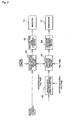
- Fig. 1 is a drawing showing the structure of one embodiment, where a battery B1, being a dc power source, is a secondary battery such as a nickel metal hydride (NiMH) or lithium ion battery.
- a battery B1 being a dc power source
- a secondary battery such as a nickel metal hydride (NiMH) or lithium ion battery.
- NiMH nickel metal hydride
- One end of a reactor L1 is connected to the positive electrode of the battery B1.
- the other end of the reactor L1 is connected to an intermediate point of NPN transistors Q1 and Q1 that are connected in series (connection point of the emitter of transistor Q1 and the collector of transistor Q2).
- the collector of transistorA1 is connected to a power source line while the emitter of transistor Q2 is connected to earth.
- Diodes D1 and D2 are respectively arranged across the emitter and collector of each of the transistors Q1 and Q2 to allow current to flow from an emitter side to a collector side.
- a converter 12 is thus constituted by the reactor L1, transistors Q1 and Q1, and the diodes, D1 and D2.
- a capacitor C1 is arranged between the power source line and earth, being the output of the converter 12, to stabilize the power source line voltage (inverter input voltage).
- a U phase arm made up of NPN transistors Q3 and Q4 connected in series, a V phase arm made up of NPN transistors Q5 and Q6 connected in series, and a W phase arm made up of NPN transistors Q7 and Q8 connected in series are arranged between the power source line and earth.
- Diodes D3 - D8 are also arranged across the emitters and collectors of each of transistors Q3 - Q8, allowing current to flow from an emitter side to a collector side.
- An inverter 14 is constituted by these transistors Q3 - Q8 and diodes D3 - D8.
- each or the phase arms are connected to respective phase ends of respective phase coils of a motor M1.
- the motor M1 is a three-phase permanent magnet motor, constructed by connecting one end of U, V and W phase coils in common to a middle point, with the other end of the U phase coil being connected to a mid-point of the transistors Q3 and Q4, the other end of the V phase coil being connected to a mid point of the transistors Q5 and Q6, and the other end of the W phase coil being connected to a mid point of the transistors Q7 and Q8.
- the output voltage of the battery B1 is detected by a transistor 20, a voltage across the two ends of the capacitor C1, namely the inverter input voltage, is detected by a voltage sensor 22, a current value for each phase of the motor M1 is detected by current sensors 24, and these detection values are supplied to a controller 30.
- the controller 30 controls switching of the transistors Q3 - Q8 of the inverter 14 based on these sensor, detection values and a motor output command etc. to control drive of the motor M1, and also controls switching of the transistors Q1 and Q2 of the converter 12.
- the controller 30 is constituted by a microcomputer or the like, and controls operation of the inverter 14 and converter 12 by executing a specified program stored in a storage section (constituted by a flash ROM etc.).
- a structural block diagram of the controller 30 is shown in Fig. 2.
- a motor torque command value, motor current values for each phase detected by the current sensors 22 and an inverter input voltage detected by the voltage sensor 22 are provided to a motor control phase voltage operation unit 40.
- the motor control phase voltage operation unit 40 calculates voltages for each phase coil of the motor from these input signals and supplies these to an inverter PWM signal converter 42.
- the inverter PWM signal converter 42 practically generates PWM signals for turning each of the transistors Q3 - Q8 of the inverter 14 on or off and supplies the PWM signals to the bases of the transistors Q3 to Q8 to control switching of the transistors Q3 - Q8 and thereby control current in each phase of the motor M1.
- motor drive current is controlled and it is possible to control motor output torque in response to a motor torque command value.
- the motor torque value is also supplied to an inverter input voltage command operation unit 50.
- the rotational speed of the motor is also supplied to the inverter input voltage command operation unit 50, and the inverter input voltage command operation unit 50 calculates an optimum inverter input voltage value (target value) from motor rotation speed and a motor torque command value.
- This target value is supplied to a converter duty ratio operation unit 52.
- Inverter input voltage and battery voltage are also supplied to the converter duty ratio operation unit 52, and a duty ratio for setting the inverter input voltage to the target value is calculated from the input voltages.
- the output voltage of the converter 12 is controlled by controlling the on/off duty ratio of the switching elements transistor Q1 and Q2, and duty cycle is calculated so that the inverter input voltage becomes the target value.
- the calculation results are then supplied to a converter PWM signal converter 54, and this converter PWM signal converter 54 PWM controls the transistors Q1 and Q2 of the converter 12.
- the power source line voltage is lowered by increasing the on duty of the upper transistor Q1.
- the motor M1 can generate using regeneration, but when the motor M1 is in regeneration the power source line voltage increases which means that the upper transistor Q1 will be turned on and the power source line voltage is maintained as a specified value.
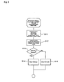
- an induced voltage constant K(T) is calculated (S11).
- the relationship of an induced voltage constant K(T) (line voltage per revolution) to torque of a permanent magnet motor is as shown in Fig. 4.
- the induced voltage constant K(T) is equivalent to a reverse voltage, and as torque increases the induced voltage constant K also increases.
- This characteristic is stored internally as a map, and an induced voltage constant K(T) is output according to a motor torque command value (T). This characteristic differs depending on individual motor characteristics, and is obtained in advance for each motor.
- Vmot K (T) ⁇ N/ ⁇
- the conversion factor is about 0.61 - 0.78.
- a corresponding induced voltage constant K(T) is determined from motor torque, voltage applied to the motor is determined from rotational speed at that time, and inverter input voltage (dc voltage) is obtained by dividing the applied voltage by the conversion factor ⁇ .
- inverter input voltage Vdc is made Vmax (S14).
- decision in S13 is NO, there is no problem and so inverter input voltage Vdc is made Vmot (S15). That is, as shown in Fig. 5, an inverter input voltage target value Vdc is raised to the system upper limit voltage Vmax in response to motor optimum drive voltage Vmot which increases with rotational speed, and after reaching the system upper limit voltage Vmax that target value Vdc is maintained at Vmax.
- inverter input voltage target value Vdc is calculated in the inverter input voltage command operation unit 50.
- optimum applied voltage for the motor at that time is calculated based on motor rotational speed and an output torque command, and an inverter input voltage command value is determined based on this applied voltage. Accordingly, efficient drive of the motor can be achieved through application of an optimum voltage based on drive conditions of the motor at that time. That is, if the inverter input voltage and motor applied voltage at the time of high motor output torque correspond, a correspondingly large current must flow. Energy loss in the inverter and the motor therefore becomes large. Loss due to a resistive component of a line etc. is also large. With this embodiment it is possible to prevent this type of deterioration in efficiency by raising the inverter input voltage. Also, since it is possible to reduce the maximum current amount, it is also possible to miniaturize and reduce the cost of the inverter and motor.
- a flowchart of another embodiment is shown in Fig. 6. With this example, it is assumed that a calculated inverter input voltage Vd is lower than battery voltage.
- the inverter input voltage command operation unit 50 calculates the inverter input voltage target value Vdc as described above (S24), and it is determined whether the obtained target value Vdc is larger than the battery voltage VB. If the decision is YES, boosting should be carried out and so the inverter input voltage target value is made Vdc as it is (S26), and the converter duty ratio operation unit 52 calculates duty ratio for the converter 12 (S27). On the other hand, if the decision in S25 is NO, boost by the converter 12 is not necessary. Inverter input voltage target value is then set to VB (S28) and the upper transistor Q1 of the converter is turned on (S29). In this way, the power source line of the inverter is connected as it is to the battery B1 through the reactor L1.
- the converter 12 has a three-phase structure.
- Reactors L1, L2 and L3 and transistors Q1, Q2, Q9, Q10, Q11 and Q12 are provided. That is, the reactors L2 and L3 have one end connected together with the reactor L1 to the positive terminal of the battery B1. Also, the other end of the reactor L2 is connected to a power source line through transistor Q9, and to earth through transistor Q10. Similarly, the other end of the reactor L3 is connected to the power source line through transistor Q11 and connected to earth through transistor Q12. Diodes allowing current to flow in the direction of emitter to collector are also connected to each of the transistors Q9 - Q12.
- a high voltage is generated at the other end (inverter side) of the reactors L1, L2 and L3 by switching respective transistors Q1, Q2, Q9, Q10, Q11 and Q12, and it is possible to perform boosting.
- by having three phases in this way it is possible to carry out boosting with suppressed ripple by sequentially switching the transistor on and off.
- the converter 12 is formed as a full bridge. Specifically, one end of the reactor L1 is not connected directly to the positive electrode of the battery B1, but is connected to the positive electrode through an NPN transistor Q13, and is connected to earth through an NPN transistor Q14. That is, one end of the reactor L1 is connected to the emitter of transistor Q13 and also to the collector of transistor Q14. The collector of transistor Q13 is then connected to the positive electrode of the battery B1, and the emitter of transistor Q14 is connected to earth. Diodes allowing current to flow in a direction from emitter to collector are also connected to these transistors Q13 and Q14.
- an inverter input voltage target value Vdc is lower that battery voltage VB, it is possible to obtain that target output voltage in the converter 12. In this case also, it is possible to always drive the motor with optimum efficiency. For example, by making the inverter input voltage low, it is possible to increase the period that switching elements of the inverter are full on, and it is possible to reduce switching loss.
- Fig. 9 shows still another embodiment of the present invention.
- two inverters and two motors are provided.
- An inverter 16 is provided between the power source line and earth, as well as the inverter 14, and a motor M2 is connected to this inverter 16.
- the structure of this inverter 16 is the same as that of the inverter 14, and the motor M2 also has ends of respective phase coils connected to mid points of respective phase arms of the inverter 16. Motor current of each phase arm of the inverter 16 is also detected by current sensors 28 and supplied to the controller 30.
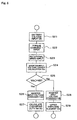
- battery voltage VB is taken in (S31).
- a motor M1 torque command 1 and motor rotational speed N1 are taken in (S32, S33).
- An inverter input voltage target value for driving motor M1 is then calculated (S34).
- a motor M2 torque command 2 and motor rotational speed N2 are taken in (S35, S36), and an inverter input voltage target value for driving motor M2 is then calculated (S37).
- the inverter input voltage target value is set to VB (S39), and the upper transistor Q1 of the converter is turned on (S40).
- the inverter input voltage target value is set to Vdc1 (S41), and the duty ratio of the converter 12 is calculated (S42). If it is determined in S38 that Vdc2 is the largest, the inverter input voltage target value is set to Vdc2 (S43), and the duty ratio of the converter 12 is calculated (S44).
- the inverter input voltage target value is set to whichever of Vdc1 and Vdc2 is the largest voltage.
- the present invention can be uses in drive control for a traveling motor of a hybrid vehicle or an electric vehicle.
Applications Claiming Priority (3)
| Application Number | Priority Date | Filing Date | Title |
|---|---|---|---|
| JP2001234824 | 2001-08-02 | ||
| JP2001234824 | 2001-08-02 | ||
| PCT/JP2002/007800 WO2003015254A1 (fr) | 2001-08-02 | 2002-07-31 | Appareil de commande d'entrainement de moteur |
Publications (3)
| Publication Number | Publication Date |
|---|---|
| EP1414145A1 true EP1414145A1 (fr) | 2004-04-28 |
| EP1414145A4 EP1414145A4 (fr) | 2008-10-29 |
| EP1414145B1 EP1414145B1 (fr) | 2019-12-25 |
Family
ID=19066364
Family Applications (1)
| Application Number | Title | Priority Date | Filing Date |
|---|---|---|---|
| EP02755717.2A Expired - Lifetime EP1414145B1 (fr) | 2001-08-02 | 2002-07-31 | Appareil de commande d'entrainement de moteur |
Country Status (6)
| Country | Link |
|---|---|
| US (1) | US7164253B2 (fr) |
| EP (1) | EP1414145B1 (fr) |
| JP (1) | JP3797361B2 (fr) |
| KR (2) | KR20070055584A (fr) |
| CN (1) | CN1537355A (fr) |
| WO (1) | WO2003015254A1 (fr) |
Cited By (8)
| Publication number | Priority date | Publication date | Assignee | Title |
|---|---|---|---|---|
| WO2005081387A1 (fr) * | 2004-02-19 | 2005-09-01 | Toyota Jidosha Kabushiki Kaisha | Dispositif de conversion de la tension |
| EP2056445A2 (fr) | 2007-11-02 | 2009-05-06 | Hamilton Sundstrand Corporation | Commande de moteur électrique dotée d'un convertisseur élévateur/réducteur |
| EP2133991A1 (fr) * | 2008-06-09 | 2009-12-16 | Grundfos Management A/S | Agrégat de pompe centrifuge |
| WO2012131073A3 (fr) * | 2011-04-01 | 2013-10-17 | Siemens Aktiengesellschaft | Procédé pour produire une tension de sortie et système pour mettre en œuvre le procédé |
| EP2824314A3 (fr) * | 2013-07-08 | 2015-06-17 | Yamaha Hatsudoki Kabushiki Kaisha | Démarreur-générateur et son procédé de commande |
| EP2955053A1 (fr) * | 2014-05-21 | 2015-12-16 | Jtekt Corporation | Dispositif de commande de machine électrique rotative |
| EP2001124A4 (fr) * | 2006-03-24 | 2017-07-12 | Toyota Jidosha Kabushiki Kaisha | Systeme de commande entraine par un moteur et son procede de commande |
| EP2546088B1 (fr) * | 2010-03-10 | 2022-11-16 | NTN Corporation | Système d'entraînement à moteur pour véhicule électrique |
Families Citing this family (74)
| Publication number | Priority date | Publication date | Assignee | Title |
|---|---|---|---|---|
| JP3632657B2 (ja) * | 2001-12-20 | 2005-03-23 | トヨタ自動車株式会社 | 電圧変換装置 |
| JP4467257B2 (ja) * | 2002-06-28 | 2010-05-26 | 株式会社日立製作所 | データベース管理方法および装置並びにその処理プログラム |
| JP3928559B2 (ja) * | 2003-01-10 | 2007-06-13 | トヨタ自動車株式会社 | 電圧変換装置、故障処理をコンピュータに実行させるプログラムを記録したコンピュータ読取り可能な記録媒体および故障処理方法 |
| JP2004260964A (ja) * | 2003-02-27 | 2004-09-16 | Shigumaa Giken Kk | 文書細断装置 |
| JP4280573B2 (ja) * | 2003-07-31 | 2009-06-17 | トヨタ自動車株式会社 | 負荷駆動装置 |
| JP4364651B2 (ja) * | 2004-01-07 | 2009-11-18 | 三菱電機株式会社 | 昇圧装置及びモータ制御装置 |
| JP4193704B2 (ja) * | 2004-01-20 | 2008-12-10 | トヨタ自動車株式会社 | 電源装置およびそれを搭載する自動車 |
| US7378808B2 (en) * | 2004-05-25 | 2008-05-27 | Caterpillar Inc. | Electric drive system having DC bus voltage control |
| JP3938179B2 (ja) * | 2004-11-18 | 2007-06-27 | 松下電器産業株式会社 | 交流電源直結型ブラシレスdcモータおよびそれを搭載した電気機器 |
| JP2006246618A (ja) * | 2005-03-03 | 2006-09-14 | Sanden Corp | インバータ装置 |
| JP4737195B2 (ja) * | 2005-03-09 | 2011-07-27 | トヨタ自動車株式会社 | 負荷駆動装置、車両、および負荷駆動装置における異常処理方法 |
| JP4218671B2 (ja) * | 2005-10-13 | 2009-02-04 | トヨタ自動車株式会社 | ハイブリッド車両の動力出力装置 |
| CN101317321A (zh) * | 2005-11-29 | 2008-12-03 | 丰田自动车株式会社 | 用于电动车辆的dc-dc变压器 |
| JP4710588B2 (ja) * | 2005-12-16 | 2011-06-29 | トヨタ自動車株式会社 | 昇圧コンバータの制御装置 |
| KR101156768B1 (ko) * | 2005-12-26 | 2012-06-18 | 두산인프라코어 주식회사 | 보조 전원을 구비한 모터 드라이브 시스템 |
| KR101203431B1 (ko) * | 2006-02-06 | 2012-11-21 | 에이비비 리써치 리미티드 | 기계적 프레스 구동 시스템 |
| JP4274188B2 (ja) * | 2006-02-08 | 2009-06-03 | トヨタ自動車株式会社 | ハイブリッド車両の駆動装置 |
| JP4640200B2 (ja) * | 2006-02-10 | 2011-03-02 | トヨタ自動車株式会社 | 電圧変換装置および電圧変換器の制御方法 |
| DE102006009312A1 (de) * | 2006-03-01 | 2007-09-06 | Jungheinrich Aktiengesellschaft | Flurförderzeug mit einem Ladegerät |
| JP4802849B2 (ja) * | 2006-05-09 | 2011-10-26 | トヨタ自動車株式会社 | モータ駆動装置 |
| JP4179351B2 (ja) * | 2006-07-07 | 2008-11-12 | トヨタ自動車株式会社 | 電源システムおよびそれを備えた車両、電源システムの制御方法、ならびに電源システムの制御をコンピュータに実行させるためのプログラムを記録したコンピュータ読取可能な記録媒体 |
| JP5315053B2 (ja) * | 2006-08-30 | 2013-10-16 | Thk株式会社 | 永久磁石界磁型リニアモータ用電力供給装置、及び永久磁石界磁型モータ用pwmインバータ |
| GB0618751D0 (en) * | 2006-09-22 | 2006-11-01 | Switched Reluctance Drives Ltd | Operating electrical machines from a DC link |
| US7609050B2 (en) * | 2007-02-20 | 2009-10-27 | Gm Global Technology Operations, Inc. | Method and system for determing current in an electrical component in a power conversion system |
| JP4221494B2 (ja) | 2007-03-29 | 2009-02-12 | トヨタ自動車株式会社 | ハイブリッド車両の制御装置 |
| JP2008295280A (ja) * | 2007-04-27 | 2008-12-04 | Meidensha Corp | モータ駆動装置 |
| WO2008136212A1 (fr) * | 2007-04-27 | 2008-11-13 | Meidensha Corporation | Entraînement moteur |
| JP4816575B2 (ja) * | 2007-06-06 | 2011-11-16 | トヨタ自動車株式会社 | 電源システムおよびそれを備えた車両、ならびに電源システムの制御方法およびその制御方法をコンピュータに実行させるためのプログラムを記録したコンピュータ読取可能な記録媒体 |
| JP2009095099A (ja) * | 2007-10-04 | 2009-04-30 | Univ Of Ryukyus | 永久磁石同期電動機のパルス振幅変調制御装置 |
| US7652443B2 (en) * | 2007-10-24 | 2010-01-26 | Gm Global Technology Operations, Inc. | Method and system for controlling a power inverter in electric drives |
| JP2009148073A (ja) * | 2007-12-14 | 2009-07-02 | Mazda Motor Corp | バッテリの充電方法および充電装置 |
| JP4424427B2 (ja) | 2008-03-18 | 2010-03-03 | トヨタ自動車株式会社 | 車両の制御装置および制御方法 |
| JP4512145B2 (ja) * | 2008-03-21 | 2010-07-28 | ファナック株式会社 | モータ制御装置 |
| JP5029914B2 (ja) * | 2008-07-31 | 2012-09-19 | アイシン・エィ・ダブリュ株式会社 | 回転電機制御システム及び車両駆動システム |
| US20100102568A1 (en) * | 2008-10-23 | 2010-04-29 | Rodolphe Juan Jacques Bonin | Electric Power Generating System Using Permanent Magent Motors |
| US8575875B2 (en) * | 2009-05-27 | 2013-11-05 | Toyota Jidosha Kabushiki Kaisha | Control device for voltage converter, vehicle equipped with the same, and control method for voltage converter |
| JP5246508B2 (ja) | 2009-05-28 | 2013-07-24 | アイシン・エィ・ダブリュ株式会社 | 電動機駆動装置の制御装置 |
| CN102510815A (zh) * | 2009-07-03 | 2012-06-20 | Inkar-M科研生产企业股份有限公司 | 电动车辆 |
| WO2011021265A1 (fr) * | 2009-08-17 | 2011-02-24 | 三菱電機株式会社 | Véhicule électrique et dispositif de conversion d'énergie |
| JP5297953B2 (ja) * | 2009-09-08 | 2013-09-25 | トヨタ自動車株式会社 | 電動車両の電動機駆動システム |
| EP2586643B1 (fr) | 2010-06-24 | 2018-01-03 | Panasonic Intellectual Property Management Co., Ltd. | Appareil d'alimentation pour véhicule électrique |
| DE112010006059B4 (de) | 2010-12-08 | 2020-08-13 | Denso Corporation | Spannungswandlungssteuervorrichtung für mehrere Motoren |
| DE112011105157B4 (de) * | 2011-04-18 | 2018-07-19 | Toyota Jidosha Kabushiki Kaisha | Motorspannungswandlungssteuervorrichtung |
| FR2979770B1 (fr) * | 2011-09-01 | 2013-09-13 | Converteam Technology Ltd | Convertisseur de puissance elevee avec des transistors de faible puissance connectes en parallele |
| KR101283892B1 (ko) * | 2011-12-07 | 2013-07-08 | 기아자동차주식회사 | 친환경 차량에서 dc-dc컨버터 제어장치 및 방법 |
| DE102012202173B4 (de) * | 2012-02-14 | 2013-08-29 | Siemens Aktiengesellschaft | Verfahren zum Betrieb eines mehrphasigen, modularen Multilevelstromrichters |
| EP2978627B1 (fr) * | 2013-03-27 | 2017-05-24 | ABB Schweiz AG | Onduleur d'entraînement partagé par différents moteurs dans un véhicule |
| CN104333291B (zh) * | 2013-07-22 | 2017-08-04 | 西门子公司 | 电机驱动控制装置及控制方法 |
| JP5664733B1 (ja) * | 2013-09-24 | 2015-02-04 | ダイキン工業株式会社 | 直接形電力変換装置の制御方法 |
| JP5794273B2 (ja) * | 2013-10-07 | 2015-10-14 | ダイキン工業株式会社 | 直接形電力変換装置の制御方法 |
| CN105829226B (zh) * | 2013-12-18 | 2020-04-14 | 奥的斯电梯公司 | 用于再生多电平驱动器的pwm策略 |
| CN103738153B (zh) * | 2013-12-19 | 2016-09-28 | 广西科技大学 | 一种新能源汽车的电驱动系统 |
| DE102014203781A1 (de) * | 2014-02-28 | 2015-09-03 | Schmidhauser Ag | Frequenzumrichter |
| JP6001587B2 (ja) | 2014-03-28 | 2016-10-05 | 株式会社デンソー | 電力変換装置 |
| JP6301748B2 (ja) * | 2014-06-23 | 2018-03-28 | トヨタ自動車株式会社 | 電動車両 |
| US9399407B2 (en) * | 2014-08-19 | 2016-07-26 | General Electric Company | Vehicle propulsion system having an energy storage system and optimized method of controlling operation thereof |
| JP6256314B2 (ja) * | 2014-11-19 | 2018-01-10 | トヨタ自動車株式会社 | 車両 |
| JP6183339B2 (ja) * | 2014-12-02 | 2017-08-23 | トヨタ自動車株式会社 | ハイブリッド自動車 |
| US20190047420A1 (en) * | 2016-03-18 | 2019-02-14 | Honda Motor Co., Ltd. | Electric power control device and vehicle |
| US10224849B2 (en) | 2016-06-06 | 2019-03-05 | Deere & Company | System and method for an inverter for self-excitation of an induction machine |
| US10014807B2 (en) * | 2016-06-06 | 2018-07-03 | Deere & Company | System and method for an inverter for self-excitation of an induction machine |
| JP6336005B2 (ja) | 2016-11-04 | 2018-06-06 | 三菱電機株式会社 | パワードライブユニットの制御装置および制御方法 |
| JP6503413B2 (ja) * | 2017-05-31 | 2019-04-17 | 本田技研工業株式会社 | Dc/dcコンバータおよび電気機器 |
| JP2019057993A (ja) * | 2017-09-20 | 2019-04-11 | トヨタ自動車株式会社 | 電力変換回路 |
| US10611363B2 (en) * | 2017-10-12 | 2020-04-07 | Ford Global Technologies, Llc | Methods and system for operating a variable voltage controller |
| JP6954205B2 (ja) | 2018-03-28 | 2021-10-27 | トヨタ自動車株式会社 | 電力変換器 |
| US11870377B2 (en) | 2018-12-24 | 2024-01-09 | Quantentech Limited | Multi-phase motor/generator system with harmonic injection |
| EP3726719A1 (fr) * | 2019-04-15 | 2020-10-21 | Infineon Technologies Austria AG | Convertisseur de puissance et procédé de conversion de puissance |
| JP7406379B2 (ja) * | 2020-01-09 | 2023-12-27 | 株式会社日立産機システム | 電力変換システムおよびそれによるモータ制御方法 |
| JP6907364B1 (ja) | 2020-03-06 | 2021-07-21 | 日立Astemo株式会社 | モータ制御装置 |
| JP6997236B2 (ja) | 2020-03-06 | 2022-01-17 | 本田技研工業株式会社 | モータ制御装置 |
| JP2023001500A (ja) | 2021-06-21 | 2023-01-06 | スミダコーポレーション株式会社 | インバータ回路及び電界結合式非接触給電装置 |
| CN114384845A (zh) * | 2022-01-06 | 2022-04-22 | 盐城工学院 | 一种基于单片机的电机扭力大小智能控制系统 |
| CN115416495A (zh) * | 2022-08-12 | 2022-12-02 | 华为数字能源技术有限公司 | 一种用于驱动电机的控制器及其相关设备 |
Citations (4)
| Publication number | Priority date | Publication date | Assignee | Title |
|---|---|---|---|---|
| US5373223A (en) * | 1989-07-27 | 1994-12-13 | Seiko Epson Corporation | Power converter/inverter system with instantaneous real power feedback control |
| US5373195A (en) * | 1992-12-23 | 1994-12-13 | General Electric Company | Technique for decoupling the energy storage system voltage from the DC link voltage in AC electric drive systems |
| EP0825059A2 (fr) * | 1996-08-22 | 1998-02-25 | Toyota Jidosha Kabushiki Kaisha | Régulateur pour l'entraínement d'un moteur synchrone à aimant permanent |
| JPH11341897A (ja) * | 1998-05-26 | 1999-12-10 | Toyota Motor Corp | モータシステム異常検出方法、異常検出装置、および、その異常検出機能を備えたモータシステム |
Family Cites Families (27)
| Publication number | Priority date | Publication date | Assignee | Title |
|---|---|---|---|---|
| US4292531A (en) * | 1977-12-27 | 1981-09-29 | General Electric Company | Electrical propulsion process and system for a traction vehicle with an on-board source of power |
| US4263535A (en) * | 1978-09-29 | 1981-04-21 | Bucyrus-Erie Company | Motor drive system for an electric mining shovel |
| GB2098367B (en) | 1981-05-08 | 1985-03-06 | Marconi Co Ltd | A controllable power source |
| US4467408A (en) * | 1982-12-29 | 1984-08-21 | General Electric Company | Means for controlling a forced commutated ac-to-dc electric rectifying circuit to avoid commutation failure |
| JPH0817597B2 (ja) | 1984-06-22 | 1996-02-21 | 株式会社日立製作所 | 交流電動機の駆動装置 |
| JP2584287B2 (ja) * | 1988-08-29 | 1997-02-26 | ファナック株式会社 | トグル式型締装置 |
| JPH0728555B2 (ja) * | 1989-06-02 | 1995-03-29 | 三菱電機株式会社 | 可変速駆動装置 |
| JP2798988B2 (ja) * | 1989-07-28 | 1998-09-17 | 株式会社東芝 | 空気調和装置用可調整交流電源装置 |
| US5359154A (en) * | 1989-12-15 | 1994-10-25 | Anritsu Corporation | Conveyor apparatus having plural conveyors with equalized conveying speeds controlled by an inverter means |
| US5420777A (en) | 1993-06-07 | 1995-05-30 | Nec Corporation | Switching type DC-DC converter having increasing conversion efficiency at light load |
| US5396214A (en) * | 1993-10-21 | 1995-03-07 | General Electric Company | Dynamic braking grid resistor configuration for reducing EMI in an electric traction motor vehicle |
| JP3597591B2 (ja) | 1994-12-05 | 2004-12-08 | 関西電力株式会社 | モータの駆動装置 |
| US5589743A (en) * | 1995-03-03 | 1996-12-31 | General Electric Company | Integrated cranking inverter and boost converter for a series hybrid drive system |
| JP3245334B2 (ja) | 1995-08-03 | 2002-01-15 | 本田技研工業株式会社 | 電動車両の電源制御装置 |
| JP3613907B2 (ja) | 1996-10-18 | 2005-01-26 | 株式会社デンソー | スイッチング電源装置 |
| JP3277825B2 (ja) | 1996-10-25 | 2002-04-22 | トヨタ自動車株式会社 | 充電装置 |
| KR100323931B1 (ko) * | 1997-08-07 | 2002-08-08 | 가부시끼가이샤 도시바 | 전동기제어장치및이제어장치를이용한공기조화기 |
| JPH1169882A (ja) | 1997-08-27 | 1999-03-09 | Mitsubishi Electric Corp | 空気調和機のモータ駆動装置 |
| JPH11299290A (ja) * | 1998-04-17 | 1999-10-29 | Hitachi Ltd | 交流電動機駆動システム |
| JP3385986B2 (ja) * | 1998-12-18 | 2003-03-10 | 本田技研工業株式会社 | シリーズハイブリッド車の出力制御装置 |
| EP1052769B1 (fr) * | 1999-05-14 | 2016-01-06 | Nissan Motor Co., Ltd. | Onduleur et moteur |
| JP2000324891A (ja) | 1999-05-14 | 2000-11-24 | Nissan Motor Co Ltd | インバータ駆動モータ |
| JP4116292B2 (ja) | 1999-09-20 | 2008-07-09 | 株式会社日立製作所 | ハイブリッド車用電動発電システム |
| JP2001157487A (ja) * | 1999-11-26 | 2001-06-08 | Nissan Motor Co Ltd | 回転電機の制御装置 |
| JP4489238B2 (ja) | 2000-03-29 | 2010-06-23 | 正行 服部 | 電動機制御装置 |
| JP4023171B2 (ja) * | 2002-02-05 | 2007-12-19 | トヨタ自動車株式会社 | 負荷駆動装置、負荷駆動装置における電力貯蔵装置の充電制御方法および充電制御をコンピュータに実行させるためのプログラムを記録したコンピュータ読取可能な記録媒体 |
| US6831442B2 (en) * | 2002-07-03 | 2004-12-14 | General Motors Corporation | Utilizing zero-sequence switchings for reversible converters |
-
2002
- 2002-07-31 JP JP2003520060A patent/JP3797361B2/ja not_active Expired - Lifetime
- 2002-07-31 CN CNA028151097A patent/CN1537355A/zh active Pending
- 2002-07-31 KR KR1020077007835A patent/KR20070055584A/ko not_active Application Discontinuation
- 2002-07-31 KR KR1020047001231A patent/KR100739391B1/ko active IP Right Grant
- 2002-07-31 WO PCT/JP2002/007800 patent/WO2003015254A1/fr active Application Filing
- 2002-07-31 US US10/484,385 patent/US7164253B2/en not_active Expired - Lifetime
- 2002-07-31 EP EP02755717.2A patent/EP1414145B1/fr not_active Expired - Lifetime
Patent Citations (4)
| Publication number | Priority date | Publication date | Assignee | Title |
|---|---|---|---|---|
| US5373223A (en) * | 1989-07-27 | 1994-12-13 | Seiko Epson Corporation | Power converter/inverter system with instantaneous real power feedback control |
| US5373195A (en) * | 1992-12-23 | 1994-12-13 | General Electric Company | Technique for decoupling the energy storage system voltage from the DC link voltage in AC electric drive systems |
| EP0825059A2 (fr) * | 1996-08-22 | 1998-02-25 | Toyota Jidosha Kabushiki Kaisha | Régulateur pour l'entraínement d'un moteur synchrone à aimant permanent |
| JPH11341897A (ja) * | 1998-05-26 | 1999-12-10 | Toyota Motor Corp | モータシステム異常検出方法、異常検出装置、および、その異常検出機能を備えたモータシステム |
Non-Patent Citations (1)
| Title |
|---|
| See also references of WO03015254A1 * |
Cited By (16)
| Publication number | Priority date | Publication date | Assignee | Title |
|---|---|---|---|---|
| US7379313B2 (en) | 2004-02-19 | 2008-05-27 | Toyota Jidosha Kabushiki Kaisha | Voltage conversion device |
| WO2005081387A1 (fr) * | 2004-02-19 | 2005-09-01 | Toyota Jidosha Kabushiki Kaisha | Dispositif de conversion de la tension |
| EP2001124A4 (fr) * | 2006-03-24 | 2017-07-12 | Toyota Jidosha Kabushiki Kaisha | Systeme de commande entraine par un moteur et son procede de commande |
| EP2056445A2 (fr) | 2007-11-02 | 2009-05-06 | Hamilton Sundstrand Corporation | Commande de moteur électrique dotée d'un convertisseur élévateur/réducteur |
| EP2056445A3 (fr) * | 2007-11-02 | 2012-08-29 | Hamilton Sundstrand Corporation | Commande de moteur électrique dotée d'un convertisseur élévateur/réducteur |
| EP2133991A1 (fr) * | 2008-06-09 | 2009-12-16 | Grundfos Management A/S | Agrégat de pompe centrifuge |
| WO2009149796A2 (fr) * | 2008-06-09 | 2009-12-17 | Grundfos Management A/S | Ensemble pompe centrifuge |
| WO2009149796A3 (fr) * | 2008-06-09 | 2010-03-18 | Grundfos Management A/S | Ensemble pompe centrifuge |
| RU2455750C1 (ru) * | 2008-06-09 | 2012-07-10 | Грундфос Менеджмент А/С | Центробежный насосный агрегат |
| US8690549B2 (en) | 2008-06-09 | 2014-04-08 | Grundfos Management A/S | Centrifugal pump unit |
| CN102057566B (zh) * | 2008-06-09 | 2014-06-11 | 格伦德福斯管理联合股份公司 | 离心泵组 |
| EP2546088B1 (fr) * | 2010-03-10 | 2022-11-16 | NTN Corporation | Système d'entraînement à moteur pour véhicule électrique |
| WO2012131073A3 (fr) * | 2011-04-01 | 2013-10-17 | Siemens Aktiengesellschaft | Procédé pour produire une tension de sortie et système pour mettre en œuvre le procédé |
| US9899917B2 (en) | 2011-04-01 | 2018-02-20 | Siemens Aktiengesellschaft | Method for producing an output voltage and assembly for performing the method |
| EP2824314A3 (fr) * | 2013-07-08 | 2015-06-17 | Yamaha Hatsudoki Kabushiki Kaisha | Démarreur-générateur et son procédé de commande |
| EP2955053A1 (fr) * | 2014-05-21 | 2015-12-16 | Jtekt Corporation | Dispositif de commande de machine électrique rotative |
Also Published As
| Publication number | Publication date |
|---|---|
| KR100739391B1 (ko) | 2007-07-13 |
| EP1414145B1 (fr) | 2019-12-25 |
| US20040165868A1 (en) | 2004-08-26 |
| EP1414145A4 (fr) | 2008-10-29 |
| JP3797361B2 (ja) | 2006-07-19 |
| WO2003015254A1 (fr) | 2003-02-20 |
| KR20070055584A (ko) | 2007-05-30 |
| KR20040019372A (ko) | 2004-03-05 |
| CN1537355A (zh) | 2004-10-13 |
| US7164253B2 (en) | 2007-01-16 |
| JPWO2003015254A1 (ja) | 2004-12-02 |
Similar Documents
| Publication | Publication Date | Title |
|---|---|---|
| EP1414145B1 (fr) | Appareil de commande d'entrainement de moteur | |
| US7102903B2 (en) | Drive apparatus, control method for the drive apparatus, storage medium storing a program controlling the drive apparatus, and power output apparatus | |
| US8884564B2 (en) | Voltage converter and voltage converter system including voltage converter | |
| CN102602299B (zh) | 电动车辆用电源装置 | |
| US7417393B2 (en) | Load driver capable of suppressing overcurrent | |
| US20070029954A1 (en) | Voltage converter control apparatus and method | |
| WO2009011444A1 (fr) | Véhicule | |
| US11757298B2 (en) | Charging system and method using motor driving system | |
| WO2019244680A1 (fr) | Système d'alimentation de véhicule électrique | |
| US5712549A (en) | DC Motor drive assembly having a controller/charge with regenerative braking | |
| JPS5961402A (ja) | バツテリ駆動車の充電装置 | |
| JP5304277B2 (ja) | 電池ハイブリッドシステム及びその使用方法 | |
| CN108482102B (zh) | 混合动力驱动系统 | |
| JP2002291256A (ja) | 動力出力装置 | |
| JP6547672B2 (ja) | 電動機装置 | |
| US11607968B1 (en) | Integrated traction battery power system for electric vehicle applications | |
| JPH0956197A (ja) | 自動車用電力変換装置 | |
| JP4590959B2 (ja) | 電力変換装置の制御方法、及びこれを用いて駆動される電気車両 | |
| US20220289053A1 (en) | Energy conversion apparatus and vehicle | |
| EP4108507A1 (fr) | Système de charge de batterie de véhicule à l'aide d'un système de commande de moteur | |
| JP7021846B2 (ja) | 制御装置 | |
| JP2022109098A (ja) | 電源装置 | |
| JP2022084326A (ja) | Dc/dcコンバータの制御装置 | |
| CN115635866A (zh) | 利用电机驱动系统对车辆的电池充电的系统 | |
| CN117901677A (zh) | 兼容加热、充电的动力总成及开关电路、车辆和控制方法 |
Legal Events
| Date | Code | Title | Description |
|---|---|---|---|
| PUAI | Public reference made under article 153(3) epc to a published international application that has entered the european phase |
Free format text: ORIGINAL CODE: 0009012 |
|
| 17P | Request for examination filed |
Effective date: 20040129 |
|
| AK | Designated contracting states |
Kind code of ref document: A1 Designated state(s): AT BE BG CH CY CZ DE DK EE ES FI FR GB GR IE IT LI LU MC NL PT SE SK TR |
|
| A4 | Supplementary search report drawn up and despatched |
Effective date: 20080925 |
|
| RIC1 | Information provided on ipc code assigned before grant |
Ipc: B60L 11/18 20060101ALI20080919BHEP Ipc: H02M 7/48 20070101AFI20030226BHEP Ipc: H02M 3/158 20060101ALI20080919BHEP |
|
| 17Q | First examination report despatched |
Effective date: 20090605 |
|
| RAP1 | Party data changed (applicant data changed or rights of an application transferred) |
Owner name: TOYOTA JIDOSHA KABUSHIKI KAISHA |
|
| REG | Reference to a national code |
Ref country code: DE Ref legal event code: R079 Ref document number: 60250071 Country of ref document: DE Free format text: PREVIOUS MAIN CLASS: H02M0007480000 Ipc: H02M0003158000 |
|
| RIC1 | Information provided on ipc code assigned before grant |
Ipc: H02M 7/48 20070101ALI20190520BHEP Ipc: B60L 50/51 20190101ALI20190520BHEP Ipc: H02M 3/158 20060101AFI20190520BHEP |
|
| GRAP | Despatch of communication of intention to grant a patent |
Free format text: ORIGINAL CODE: EPIDOSNIGR1 |
|
| INTG | Intention to grant announced |
Effective date: 20190710 |
|
| RBV | Designated contracting states (corrected) |
Designated state(s): DE FR |
|
| GRAS | Grant fee paid |
Free format text: ORIGINAL CODE: EPIDOSNIGR3 |
|
| GRAA | (expected) grant |
Free format text: ORIGINAL CODE: 0009210 |
|
| REG | Reference to a national code |
Ref country code: DE Ref legal event code: R081 Ref document number: 60250071 Country of ref document: DE Owner name: DENSO CORPORATION, KARIYA-SHI, JP Free format text: FORMER OWNER: TOYOTA JIDOSHA KABUSHIKI KAISHA, TOYOTA-SHI, AICHI-KEN, JP |
|
| AK | Designated contracting states |
Kind code of ref document: B1 Designated state(s): DE FR |
|
| REG | Reference to a national code |
Ref country code: DE Ref legal event code: R096 Ref document number: 60250071 Country of ref document: DE |
|
| REG | Reference to a national code |
Ref country code: DE Ref legal event code: R097 Ref document number: 60250071 Country of ref document: DE |
|
| PLBE | No opposition filed within time limit |
Free format text: ORIGINAL CODE: 0009261 |
|
| STAA | Information on the status of an ep patent application or granted ep patent |
Free format text: STATUS: NO OPPOSITION FILED WITHIN TIME LIMIT |
|
| 26N | No opposition filed |
Effective date: 20200928 |
|
| PGFP | Annual fee paid to national office [announced via postgrant information from national office to epo] |
Ref country code: FR Payment date: 20210611 Year of fee payment: 20 |
|
| REG | Reference to a national code |
Ref country code: DE Ref legal event code: R081 Ref document number: 60250071 Country of ref document: DE Owner name: DENSO CORPORATION, KARIYA-SHI, JP Free format text: FORMER OWNER: TOYOTA JIDOSHA KABUSHIKI KAISHA, TOYOTA-SHI, AICHI-KEN, JP |
|
| PGFP | Annual fee paid to national office [announced via postgrant information from national office to epo] |
Ref country code: DE Payment date: 20210721 Year of fee payment: 20 |
|
| REG | Reference to a national code |
Ref country code: DE Ref legal event code: R071 Ref document number: 60250071 Country of ref document: DE |