EP1343943B1 - Platte für den innenausbau und trockenbau sowie verfahren zum erstellen von neuen wänden eines raumes oder zur verkleidung von vorhandenen flächen eines raumes - Google Patents
Platte für den innenausbau und trockenbau sowie verfahren zum erstellen von neuen wänden eines raumes oder zur verkleidung von vorhandenen flächen eines raumes Download PDFInfo
- Publication number
- EP1343943B1 EP1343943B1 EP01988053A EP01988053A EP1343943B1 EP 1343943 B1 EP1343943 B1 EP 1343943B1 EP 01988053 A EP01988053 A EP 01988053A EP 01988053 A EP01988053 A EP 01988053A EP 1343943 B1 EP1343943 B1 EP 1343943B1
- Authority
- EP
- European Patent Office
- Prior art keywords
- panel
- plate
- plates
- groove
- connecting means
- Prior art date
- Legal status (The legal status is an assumption and is not a legal conclusion. Google has not performed a legal analysis and makes no representation as to the accuracy of the status listed.)
- Expired - Lifetime
Links
- 238000004519 manufacturing process Methods 0.000 title claims abstract description 7
- 238000010276 construction Methods 0.000 title abstract description 6
- 238000000034 method Methods 0.000 claims abstract description 23
- 238000013461 design Methods 0.000 claims abstract description 21
- 239000000463 material Substances 0.000 claims description 36
- 239000000853 adhesive Substances 0.000 claims description 33
- 230000001070 adhesive effect Effects 0.000 claims description 31
- 239000010410 layer Substances 0.000 claims description 26
- 239000002023 wood Substances 0.000 claims description 14
- 238000010438 heat treatment Methods 0.000 claims description 13
- 238000005192 partition Methods 0.000 claims description 10
- 239000003566 sealing material Substances 0.000 claims description 9
- 239000011888 foil Substances 0.000 claims description 8
- 230000001788 irregular Effects 0.000 claims description 7
- 239000004033 plastic Substances 0.000 claims description 7
- 229920003023 plastic Polymers 0.000 claims description 7
- 230000001681 protective effect Effects 0.000 claims description 7
- 238000000576 coating method Methods 0.000 claims description 6
- 238000004040 coloring Methods 0.000 claims description 6
- 239000003292 glue Substances 0.000 claims description 6
- 239000011248 coating agent Substances 0.000 claims description 5
- 239000012790 adhesive layer Substances 0.000 claims description 4
- 238000004378 air conditioning Methods 0.000 claims description 4
- 230000000694 effects Effects 0.000 claims description 4
- 239000011505 plaster Substances 0.000 claims description 4
- 239000004575 stone Substances 0.000 claims description 4
- 230000015572 biosynthetic process Effects 0.000 claims description 3
- 238000005304 joining Methods 0.000 claims description 3
- 239000011810 insulating material Substances 0.000 claims description 2
- 238000012986 modification Methods 0.000 claims description 2
- 230000004048 modification Effects 0.000 claims description 2
- 238000007373 indentation Methods 0.000 claims 1
- 238000005096 rolling process Methods 0.000 claims 1
- 230000008901 benefit Effects 0.000 description 17
- 210000001503 joint Anatomy 0.000 description 14
- 238000006073 displacement reaction Methods 0.000 description 11
- 230000007704 transition Effects 0.000 description 7
- 239000002184 metal Substances 0.000 description 6
- 229910052751 metal Inorganic materials 0.000 description 6
- 239000004640 Melamine resin Substances 0.000 description 5
- 229920000877 Melamine resin Polymers 0.000 description 5
- 239000000654 additive Substances 0.000 description 5
- 238000003780 insertion Methods 0.000 description 5
- 230000037431 insertion Effects 0.000 description 5
- 238000003825 pressing Methods 0.000 description 5
- 238000005253 cladding Methods 0.000 description 4
- 239000002131 composite material Substances 0.000 description 4
- 238000011109 contamination Methods 0.000 description 4
- 238000007667 floating Methods 0.000 description 4
- 238000009413 insulation Methods 0.000 description 4
- 239000000758 substrate Substances 0.000 description 4
- 230000003746 surface roughness Effects 0.000 description 4
- 239000011162 core material Substances 0.000 description 3
- 238000011161 development Methods 0.000 description 3
- 230000018109 developmental process Effects 0.000 description 3
- 238000000227 grinding Methods 0.000 description 3
- 238000009434 installation Methods 0.000 description 3
- 230000003287 optical effect Effects 0.000 description 3
- 230000037452 priming Effects 0.000 description 3
- 241000587161 Gomphocarpus Species 0.000 description 2
- 230000008859 change Effects 0.000 description 2
- 238000004140 cleaning Methods 0.000 description 2
- 230000000295 complement effect Effects 0.000 description 2
- 230000002349 favourable effect Effects 0.000 description 2
- 239000000835 fiber Substances 0.000 description 2
- 239000000945 filler Substances 0.000 description 2
- 238000011049 filling Methods 0.000 description 2
- 239000012774 insulation material Substances 0.000 description 2
- 239000007788 liquid Substances 0.000 description 2
- 238000003801 milling Methods 0.000 description 2
- 238000002360 preparation method Methods 0.000 description 2
- 230000008569 process Effects 0.000 description 2
- 229920005989 resin Polymers 0.000 description 2
- 239000011347 resin Substances 0.000 description 2
- 239000000565 sealant Substances 0.000 description 2
- 230000008961 swelling Effects 0.000 description 2
- 239000004753 textile Substances 0.000 description 2
- RNFJDJUURJAICM-UHFFFAOYSA-N 2,2,4,4,6,6-hexaphenoxy-1,3,5-triaza-2$l^{5},4$l^{5},6$l^{5}-triphosphacyclohexa-1,3,5-triene Chemical compound N=1P(OC=2C=CC=CC=2)(OC=2C=CC=CC=2)=NP(OC=2C=CC=CC=2)(OC=2C=CC=CC=2)=NP=1(OC=1C=CC=CC=1)OC1=CC=CC=C1 RNFJDJUURJAICM-UHFFFAOYSA-N 0.000 description 1
- 235000008733 Citrus aurantifolia Nutrition 0.000 description 1
- 241000196324 Embryophyta Species 0.000 description 1
- 229920006328 Styrofoam Polymers 0.000 description 1
- 235000011941 Tilia x europaea Nutrition 0.000 description 1
- 208000027418 Wounds and injury Diseases 0.000 description 1
- 238000005299 abrasion Methods 0.000 description 1
- NIXOWILDQLNWCW-UHFFFAOYSA-N acrylic acid group Chemical group C(C=C)(=O)O NIXOWILDQLNWCW-UHFFFAOYSA-N 0.000 description 1
- 230000009471 action Effects 0.000 description 1
- 230000006978 adaptation Effects 0.000 description 1
- 230000000996 additive effect Effects 0.000 description 1
- 238000004026 adhesive bonding Methods 0.000 description 1
- 230000002411 adverse Effects 0.000 description 1
- 229910052782 aluminium Inorganic materials 0.000 description 1
- XAGFODPZIPBFFR-UHFFFAOYSA-N aluminium Chemical compound [Al] XAGFODPZIPBFFR-UHFFFAOYSA-N 0.000 description 1
- 238000013459 approach Methods 0.000 description 1
- 239000002969 artificial stone Substances 0.000 description 1
- 239000000969 carrier Substances 0.000 description 1
- 239000004568 cement Substances 0.000 description 1
- 239000011509 cement plaster Substances 0.000 description 1
- 238000006243 chemical reaction Methods 0.000 description 1
- 150000001875 compounds Chemical class 0.000 description 1
- 239000004567 concrete Substances 0.000 description 1
- 239000007799 cork Substances 0.000 description 1
- 230000006378 damage Effects 0.000 description 1
- 239000003599 detergent Substances 0.000 description 1
- 230000003670 easy-to-clean Effects 0.000 description 1
- 238000005516 engineering process Methods 0.000 description 1
- 238000001125 extrusion Methods 0.000 description 1
- 239000003063 flame retardant Substances 0.000 description 1
- 239000003365 glass fiber Substances 0.000 description 1
- 239000011440 grout Substances 0.000 description 1
- 238000007654 immersion Methods 0.000 description 1
- 208000014674 injury Diseases 0.000 description 1
- 239000000976 ink Substances 0.000 description 1
- 230000010354 integration Effects 0.000 description 1
- 230000003993 interaction Effects 0.000 description 1
- 230000002452 interceptive effect Effects 0.000 description 1
- 239000011508 lime plaster Substances 0.000 description 1
- 230000000414 obstructive effect Effects 0.000 description 1
- 239000003973 paint Substances 0.000 description 1
- 238000010422 painting Methods 0.000 description 1
- 235000011837 pasties Nutrition 0.000 description 1
- 230000035515 penetration Effects 0.000 description 1
- 230000002093 peripheral effect Effects 0.000 description 1
- 229920001296 polysiloxane Polymers 0.000 description 1
- 229920002635 polyurethane Polymers 0.000 description 1
- 239000004814 polyurethane Substances 0.000 description 1
- 238000012545 processing Methods 0.000 description 1
- 230000009467 reduction Effects 0.000 description 1
- 239000005871 repellent Substances 0.000 description 1
- 230000002441 reversible effect Effects 0.000 description 1
- 230000000630 rising effect Effects 0.000 description 1
- 230000003678 scratch resistant effect Effects 0.000 description 1
- 238000000926 separation method Methods 0.000 description 1
- 239000007787 solid Substances 0.000 description 1
- 239000008261 styrofoam Substances 0.000 description 1
- 239000000126 substance Substances 0.000 description 1
- 239000002344 surface layer Substances 0.000 description 1
Images


Classifications
-
- E—FIXED CONSTRUCTIONS
- E04—BUILDING
- E04F—FINISHING WORK ON BUILDINGS, e.g. STAIRS, FLOORS
- E04F13/00—Coverings or linings, e.g. for walls or ceilings
- E04F13/07—Coverings or linings, e.g. for walls or ceilings composed of covering or lining elements; Sub-structures therefor; Fastening means therefor
- E04F13/08—Coverings or linings, e.g. for walls or ceilings composed of covering or lining elements; Sub-structures therefor; Fastening means therefor composed of a plurality of similar covering or lining elements
- E04F13/0801—Separate fastening elements
- E04F13/0803—Separate fastening elements with load-supporting elongated furring elements between wall and covering elements
- E04F13/081—Separate fastening elements with load-supporting elongated furring elements between wall and covering elements with additional fastening elements between furring elements and covering elements
- E04F13/0821—Separate fastening elements with load-supporting elongated furring elements between wall and covering elements with additional fastening elements between furring elements and covering elements the additional fastening elements located in-between two adjacent covering elements
- E04F13/0826—Separate fastening elements with load-supporting elongated furring elements between wall and covering elements with additional fastening elements between furring elements and covering elements the additional fastening elements located in-between two adjacent covering elements engaging side grooves running along the whole length of the covering elements
-
- E—FIXED CONSTRUCTIONS
- E04—BUILDING
- E04F—FINISHING WORK ON BUILDINGS, e.g. STAIRS, FLOORS
- E04F13/00—Coverings or linings, e.g. for walls or ceilings
- E04F13/07—Coverings or linings, e.g. for walls or ceilings composed of covering or lining elements; Sub-structures therefor; Fastening means therefor
- E04F13/08—Coverings or linings, e.g. for walls or ceilings composed of covering or lining elements; Sub-structures therefor; Fastening means therefor composed of a plurality of similar covering or lining elements
- E04F13/0801—Separate fastening elements
- E04F13/0832—Separate fastening elements without load-supporting elongated furring elements between wall and covering elements
- E04F13/0833—Separate fastening elements without load-supporting elongated furring elements between wall and covering elements not adjustable
- E04F13/0846—Separate fastening elements without load-supporting elongated furring elements between wall and covering elements not adjustable the fastening elements engaging holes or grooves in the side faces of the covering elements
-
- E—FIXED CONSTRUCTIONS
- E04—BUILDING
- E04F—FINISHING WORK ON BUILDINGS, e.g. STAIRS, FLOORS
- E04F15/00—Flooring
- E04F15/02—Flooring or floor layers composed of a number of similar elements
- E04F15/02133—Flooring or floor layers composed of a number of similar elements fixed directly to an underlayer by means of magnets, hook and loop-type or similar fasteners, not necessarily involving the side faces of the flooring elements
- E04F15/02144—Flooring or floor layers composed of a number of similar elements fixed directly to an underlayer by means of magnets, hook and loop-type or similar fasteners, not necessarily involving the side faces of the flooring elements by magnets
-
- E—FIXED CONSTRUCTIONS
- E04—BUILDING
- E04F—FINISHING WORK ON BUILDINGS, e.g. STAIRS, FLOORS
- E04F15/00—Flooring
- E04F15/02—Flooring or floor layers composed of a number of similar elements
- E04F15/04—Flooring or floor layers composed of a number of similar elements only of wood or with a top layer of wood, e.g. with wooden or metal connecting members
-
- E—FIXED CONSTRUCTIONS
- E04—BUILDING
- E04F—FINISHING WORK ON BUILDINGS, e.g. STAIRS, FLOORS
- E04F2201/00—Joining sheets or plates or panels
- E04F2201/01—Joining sheets, plates or panels with edges in abutting relationship
- E04F2201/0107—Joining sheets, plates or panels with edges in abutting relationship by moving the sheets, plates or panels substantially in their own plane, perpendicular to the abutting edges
- E04F2201/0115—Joining sheets, plates or panels with edges in abutting relationship by moving the sheets, plates or panels substantially in their own plane, perpendicular to the abutting edges with snap action of the edge connectors
-
- E—FIXED CONSTRUCTIONS
- E04—BUILDING
- E04F—FINISHING WORK ON BUILDINGS, e.g. STAIRS, FLOORS
- E04F2201/00—Joining sheets or plates or panels
- E04F2201/04—Other details of tongues or grooves
- E04F2201/041—Tongues or grooves with slits or cuts for expansion or flexibility
-
- E—FIXED CONSTRUCTIONS
- E04—BUILDING
- E04F—FINISHING WORK ON BUILDINGS, e.g. STAIRS, FLOORS
- E04F2201/00—Joining sheets or plates or panels
- E04F2201/05—Separate connectors or inserts, e.g. pegs, pins, keys or strips
- E04F2201/0517—U- or C-shaped brackets and clamps
-
- E—FIXED CONSTRUCTIONS
- E04—BUILDING
- E04F—FINISHING WORK ON BUILDINGS, e.g. STAIRS, FLOORS
- E04F2201/00—Joining sheets or plates or panels
- E04F2201/07—Joining sheets or plates or panels with connections using a special adhesive material
Definitions
- the invention relates to a plate in particular for interior and drywall, preferably for creating new walls and facing shells of a room or for covering wall, ceiling or roof surfaces of a room, according to the preamble of claim 1, and an associated method according to the preamble of claim 28.
- plates such as plasterboard
- suitable carriers For example, these panels are fixed in the drywall to create new partitions on metal profiles.
- the panels may be attached to a wall-connected battens or roof slopes, such as the beams of a roof truss, to form cladding.
- the plates can be overman high and have a width of more than 1 m.
- Such plates are known as "one-man plates” and have, for example, dimensions of about 1.50 x 1.00 m.
- there are larger by default Plates for example, with dimensions of 1.25 x 2.50 m, which can usually be handled by only two people.
- a smooth and unobtrusive transition must be created.
- the abutting edges of the plates have for this purpose in each case in the joint region of two plates a flattening.
- the plates are thus beveled at the edge, so that at the abutting edge of two adjacent plates results in a comparatively flat flattening.
- This can be filled with putty.
- the wet filler is then inserted a textile strip.
- the plates are tensile strength connected to each other, for example, to prevent later cracks in a wallpaper attached above.
- a panel element which can be connected to an adjacent panel element by means of a tongue and groove connection.
- the groove is bounded by two so-called groove cheeks. At that groove cheek, which is located on the side facing away from the space in question, recesses for receiving fasteners are present.
- the panel shown can be connected to a substructure.
- EP 1 120 515 A1 a combination of a locking element with at least two panels is known.
- a first panel is attached to a substrate by means of a clamp.
- a second panel is inserted with its spring in the groove of the first panel and by a protruding portion, which at the Clamp is formed, held on the ground and to the first panel.
- a panel element which is provided for floor coverings and is equipped with a special tongue and groove joint, with which a latching connection with adjacent panel elements is possible.
- a deflection of at least one of the groove bounding portions takes place at the time of the connection, and a latching connection is formed in that this portion at least largely moved back and holding a provided on the spring of the adjacent panel latching latching.
- JP 11350706 A for a panel which consists of metal at least on its surface.
- a plate according to the preamble of claim 1 is known from US 4 299 070. This is formed by extrusion as a largely hollow plate and is provided with connecting means in the form of tongue and groove. On the spring two undercuts are provided, in which engage projections formed on the two groove cheeks. The projections are designed to complement the undercuts. A sealing material separated from the plate material presses the connecting means into engagement with each other.
- a method according to the preamble of claim 28 is known from DE 195 03 948 A1.
- a first, already attached to a supporting structure plate is connected by a latching connection with a second plate.
- the second plate is attached to the support structure.
- the locking connection is provided with a joining play in order to be able to change a joint between the two plates.
- the invention has for its object to provide a plate especially for interior and drywall, which is time-saving with little effort and visually appealing manner with other, similar plates for forming a new wall or a panel connectable. Furthermore, a suitable method for this purpose should be created.
- connecting means which, when connected to further, like plates, allow a snap-in connection with the respective adjacent plate.
- These connecting means may be provided, for example, in the form of a tongue and groove configuration.
- the connecting means on two opposite sides are complementary to each other, so that the side edge of a plate can be connected to the opposite side edge of a similar plate latching or locking together.
- a “latching connection” is understood here to mean that an at least short-term deflection takes place in the region of the connection, in particular on one of the involved sections, for example one of the groove-defining groove cheeks, so that a (generally expressed) latching projection, which is preferably one Excessive, can be recorded.
- a (generally expressed) latching projection which is preferably one Excessive
- the section moved in this way can continue to be at least slightly deflected, so that there is always a force which pulls the plates toward one another.
- Such a latching connection has the significant advantage that in previously unknown manner plates for interior work, which are to be attached to ceilings and / or walls can be optically joint-free connected to each other.
- optically jointless is meant that, although there is a joint or joint between two adjacent panels, the joint is of such a quality and of such small dimensions that it is not perceived.
- the joint corresponds to a very well executed wallpaper impact, so that the impression of a particularly well-applied wallpaper arises, or in the case of other surface finishes, the joint is not recognizable.
- the described latching, snap or click connection prevents a moving apart of two adjacent plates, so that always a good look is ensured without having to edit the joints between the plates separately.
- connection is further formed between two plates, which connects the two plates in all directions perpendicular to the considered side edge.
- the two plates can not be raised relative to each other in a direction perpendicular to their surface. Further, they can not be readily separated from each other in a direction parallel to the surface thereof. This is prevented by the locking connection means.
- This lock applies at least for the time during use, so long as the plates form a partition or panel.
- the connecting means may be designed so that by appropriate release of the plates from each other, the plates can be separated from each other destructively and dirt-free and used again in other ways.
- the plate according to the invention is distinguished for the creation of new walls or for covering existing surfaces of a room in that additional fastening means are present on the plate itself or on two interconnected plates, which allow attachment to a supporting structure.
- these fastening devices may be present at the junction of two interconnected plates such that here attachment to a support structure by suitable brackets or adapters Metal or plastic is made possible.
- these additional fastening devices can be provided in such a way that attachment of a respective plate to a supporting structure is effected by suitable clamps, screws or nails.
- an adhesive or adhesive attachment and attachment by Velcro or magnetic tape to a support structure is possible.
- the plate according to the invention offers decisive advantages in that, on the one hand, it is significantly lighter, namely about 30%, than a plasterboard. As a result, it can be transported and mounted with little effort. Furthermore, the plate according to the invention is easy to work with, for example, a jigsaw or circular saw. On the other hand, in the case of the board according to the invention, the filling of the butt joints as well as the grinding of the filler compound is eliminated compared to the use of plasterboard panels. In this way, moreover, the extensive cleaning work can be saved in an advantageous manner, which is usually required when using plasterboard.
- the plate according to the invention is advantageously suitable as clothing for suspended ceilings, lightweight partitions, facing shells and the attic.
- a so-called "short length" of the plate could have a length of about 1.3 m, preferably 1.285 m.
- latching formed connecting means ensures that the joint between two adjacent plates is largely unobtrusive and in particular is not more conspicuous to the viewer than, for example, the joints of glued wallpaper tapes.
- these connecting means ensure that two adjacent plates are aligned with respect to their surface at the same level. If only the attachment to a supporting structure underneath were used, it would not necessarily guarantee that the panels are at the same level and could cause interfering steps on the surface.
- the connecting means formed on the plates can be made so precise that the surfaces of adjacent plates exactly flush with each other.
- the plate according to the invention can advantageously be provided with favorable building physics properties.
- the plate according to DIN 4102 is classified as B1 flame retardant.
- the classification F-30B required for detached and semi-detached houses can be achieved.
- sound and heat protection requirements can be fulfilled in an advantageous manner become.
- the plate according to the invention when executed from the wood material MDF, can be classified as a very low-pollution material that meets the requirements of the "blue angel".
- the plate according to the invention can be made air-tight or diffusion-tight to fulfill various regulations.
- the additional fastening means which serve to attach the plate to a support structure are formed by at least one recess which is present in the connected state of two plates in the connecting region of the two plates, and in which recess a portion of a mounting bracket is receivable.
- a receiving space for a portion of a mounting bracket is provided in the connection area between two similar plates according to the invention in a suitable manner.
- a particular advantage with the use of mounting brackets is that the plate according to the invention in all directions with respect to the mounting brackets movable can be appropriate.
- a larger area, which is clad with a plurality of inventive plates, in a direction perpendicular to the respective joints move or "work" so that even with a shrinkage or swelling of the plates do not open joints, because the composite of all In a sense, plates can move relative to the clamps by which the plates are held to the support structure.
- At least one groove which serves to receive a portion of a mounting bracket.
- Such a groove extends from the edge of the plate into the material of the plate, and a corresponding leg of a mounting bracket can engage in this groove, so that the plate is held on the support structure.
- At least one recess in the edge region of the plate which serves to accommodate screw or nail heads.
- These recesses can each be adapted as a countersunk hole to the head of a single screw or a single nail.
- the recess may also be formed as a groove over a certain length along the edge of the plate, so that the number of fastening means, so the screws or nails that are used, is arbitrary.
- Such a recess in the broadest sense may also be formed as a free space, which is present in the connected state of two plates in the connecting region of the plates and is suitable for the head of a screw or a nail and a slightly protruding portion of a bracket, by "stapling" can be attached to record.
- any kind of locking, snapping or clicking is conceivable for RastverbinPHg between two similar plates.
- the lower groove cheek that is opposite to the visible side of the plate boundary of the groove opposite the projection provided on the side groove protrudes.
- the additional fastening device for receiving a screw or nail head or similar fastening means can be provided without these, as it were past the upper groove cheek, must be mounted obliquely. Rather, the attachment can take place in the region projecting in relation to the upper groove cheek in a direction substantially perpendicular to the plate surface.
- the latching connection between two similar plates is further preferred that it is designed such that the two plates are mutually displaceable in a direction parallel to the mutually locked edges.
- the plate according to the invention in addition to the previously considered first and second side, which are opposite to each other, also the third and fourth sides of a rectangular plate connecting means for a snap, snap or click connection.
- a particularly secure composite of the plates in all directions, advantageously joint-free can be realized.
- the connection on the third and fourth side as explained in more detail below, by a largely flat displacement or by a lowering movement in a direction largely perpendicular to the disk surface, in a sense in the manner of a push button done.
- a gap of, for example, a maximum of 8 mm in a simple and visually appealing way and manner by a suitable profile, such as acrylic, covered or sealed by liquid, permanently elastic sealant.
- a suitable profile such as acrylic, covered or sealed by liquid, permanently elastic sealant.
- the provided on the third and fourth side groove that connects to the actual groove, which serves to receive the spring a depression.
- this depression it is preferred that it has a smaller width (viewed in cross section) than the groove which serves to receive the spring.
- the groove tapers in the direction of the plate interior to form said Deepening. This serves to provide the two groove cheeks, which limit the groove, with the flexibility that is required for the formation of the latching or snap connection. In this way, the function can be ensured, and at the same time the described short Einrastweg be realized, in view of which a comparatively small depth of the groove is sufficient.
- the recess described provides the flexibility of the groove cheeks that is advantageous for locking.
- an embodiment is also preferred, which is basically also conceivable for the first and second sides.
- a groove is provided in the broadest sense, which is open in the direction of the visible side of the plates.
- a spring extends toward the back of the disk.
- two adjacent plates are connected to each other by a movement which is substantially perpendicular to the plate surface, in the manner of a push button.
- This type of connection can be formed either by a rectilinear lowering movement in said direction on all four sides of a rectangular plate.
- the locking of a plate to be relocated on the third or fourth side can be effected by being applied to this side in the correct position of a plate already laid, and the spring protruding in the direction of the rear side swings into the groove which is open towards the top.
- a joint-free surface can be formed with adjacent plates.
- the additional fastening devices of the plate according to the invention for attachment to a supporting structure can also be formed by a self-adhesive layer, which is provided at least in sections on a rear side of the plate.
- a self-adhesive layer may be protected by a film or the like until it is attached, so that the adhesive is activated only after the film has been removed and subsequently ensures that it is fastened to a support structure for fastening the plate.
- the plate according to the invention has a suitable adapter for attachment to a portion or an element of the supporting structure.
- the supporting structure does not necessarily have to have separate elements which serve to mount the plate according to the invention.
- the cooperating with the fastening means of the plate elements may also be integrally provided on the support structure.
- a clip explained in more detail below can be designed as an integrated component, in particular as an extruded profile, on the supporting or substructure.
- the fasteners provided on the panel and the cooperating fasteners of the substructure need not necessarily be separate from the panel or substructure.
- the invention also extends to a combination of plate according to the invention with attachable to a support or support structure, attached or integrally provided fastening means, as created by such a combination advantageously a particularly simple way to create partitions or to disguise interior spaces.
- the fastening device provided on the plate according to the invention is at least one recess, for example, a milling or at least called a bore which cooperates with an element or a section attached thereto on the support structure such that the inventive plate securely on this Construction is held.
- the milling could form a detent channel or a plurality of detent openings into which a suitable section engages on the substructure and, to a certain extent in the manner of a pushbutton, fastens the panel according to the invention to the substructure.
- the attachment for example, the screwing of an adapter on the back of the plate according to the invention is conceivable.
- a corresponding counterpart would be attached to the substructure and would allow pressing, sliding or snapping the provided with one or more adapters, the invention plate.
- the plate it is preferred for the plate that it at least partially made of a wood material, in particular MDF or HDF board, or, alternatively, consists of plastic.
- the plate according to the invention may consist at least partially of a variant of the materials mentioned modified by additives or by additional layers.
- MDF board is currently a density from about 500 to 800 kg / m 3 , preferably about 750 kg / m 3 used.
- the density is a lower value, in particular about 100 to 150 kg / m 3 .
- those contours can be formed with the necessary precision, which are required for the attachment of two adjacent plates together and for the attachment of the individual plate to a support structure.
- the surface structure according to the invention can be made particularly attractive on a wood material on its surface by the pressing of a paper or a film by means of melamine resin.
- a wood material on its surface by the pressing of a paper or a film by means of melamine resin.
- an inexpensive manufacturability is ensured and, on the other hand, a problem-free way to fasten such plates.
- the described surfaces can be imitated in an advantageous manner, particularly close to reality, and made abrasion-resistant, scratch-resistant, impact-resistant and easy to clean.
- Such panels are highly resilient, since similar laminate panels are used for example as a floor covering, so that there is the possibility to use the plates without further protective after-treatment as a durable wall or ceiling panel.
- suitable fastening loads of up to 50 kg can be attached to the plate according to the invention.
- the preferred material MDF board also has the advantage that it haridelt a thermally comfortable material whose surface feels "warm” because the material has a low heat penetration. Consequently, a wall lined with the panel according to the invention feels warmer as a concrete or stone wall or a lime / cement plaster surface.
- the additional fastening devices are designed such that they are concealed in the interconnected state of two plates.
- a strip of material may be provided on the plate, which protrudes beyond the visible at the front plate edge, so that here the plate can be nailed to a support structure or screwed. This strip of material can be covered by the corresponding edge of an adjacent plate.
- the corresponding connecting means are designed so that between two interconnected plates a press fit is formed. Accordingly, two adjacent plates are in tension against each other, and there is no danger that forms an ugly joint between the two plates.
- a particularly advantageous embodiment of the plate according to the invention is that it is designed as a facing shell or partition, that it has one or two surfaces suitable as interior surfaces. In this way, a partition for a room can be created in a particularly simple manner.
- a support or substructure according to the invention attached to the plate according to the invention in a case in addition to the latching connection between two adjacent plates in such a case is called, the ceiling or the floor and in any way adapted St basicprofile where the plate can be attached by suitable means of connection.
- the plate according to the invention may also have a multilayer structure and have an intermediate layer.
- Such an intermediate layer can be formed for example by a honeycomb or hollow body plate, for example made of plastic, or a preferably 40 mm thick clamping plate, which is planked on both sides instead of the previously known plasterboard with the plate according to the invention.
- the connecting means latching in accordance with the invention, a dividing wall can be made substantially simpler in this way than is currently possible according to the prior art, in which dividing walls are created in a complex manner by means of stands and the fastening of plasterboard.
- the latching connection means may be formed both in the intermediate layer and the at least one existing upper layer.
- the attachment without the use of stands can, as mentioned, for example, be realized on-site by provided on the top and bottom edges strips that are dowelled to the floor and ceiling.
- the plate according to the invention has a surface which is provided with the typical surface structure of a handcrafted wall covering, in particular with its projections and depressions.
- a crafted wall covering which is already formed on the plate according to the invention, is a wallpaper, a plaster surface, in particular fine, coarse or structural plaster, or a surface created by a coating technique or a plaster surface.
- surfaces to be formed on existing walls or panels, such as plasterboard must be made by a variety of individual processing steps.
- the preparation of such a wall covering is usually associated with six operations, namely trowelling the butt joint between two plates, grinding, priming, wallpapering, primer and finish. Furthermore, this entails considerable contamination and the necessary disposal of numerous different individual materials. By the plate according to the invention all of the six operations described as well as the cleaning and disposal work can be saved.
- such a surface structure is already present on the plate.
- a wall in particular partition or a panel with a corresponding appearance, only a plurality of plates must be attached adjacent to each other. There is no rework, especially a troweling, a plastering or the operations in the context of wallpapering and painting required. The six operations mentioned can be saved, resulting in a total of time savings in interior design or drywall and allows two to three days earlier use of the rooms.
- the surface of the plate according to the invention can be advantageously designed so that it can be painted with a conventional color, or with a wallpaper or tile coating can be provided.
- a different color or surface finish may be made.
- the plate according to the invention which is provided for example with a primer, still accounts for four steps compared to the conventional approach, namely the troweling, grinding, priming and priming.
- the plate according to the invention may consist of the abovementioned materials, in particular of MDF board, and be modified or coated with an additive or an additional layer, so that the plate can be coated by the above-mentioned working steps.
- the plate according to the invention could also be left raw and be provided in this state with a coating or an order.
- surface structures which may be provided on the panel according to the invention all structures are conceivable which are possible and customary for the insides of rooms.
- an optic which corresponds to that of plastered walls can be formed.
- any structures known by wallpaper may be provided.
- a rough-fiber optic can be formed.
- wallpaper glass fiber mats which are essentially formed by a comparatively coarse tissue.
- the resulting structure may be provided on the surface of the plate according to the invention. This applies equally to fiber optic networks.
- a besoriders appealing appearance of the plate according to the invention results when this has a color, which also corresponds to a handcrafted color scheme. This is especially thought of an irregular color, as this arises for example in the context of a wiper, roller or sponge technology. In other words, can be replaced in this way consuming and artisanal colorations of inner walls by a corresponding factory provided color on the plate according to the invention.
- the creation of a partition or the lining of the inner surfaces of a room is therefore connected to the user with significantly less effort, in particular a Montagzeit- and cost advantage, and less pollution.
- the coloring of the surface acting as a visible surface of the plate according to the invention may further correspond to a wood or veneer optics, as well as a stone, tile or so-called fantasy decor, which may have any desired design.
- the plate according to the invention can be provided on its visible surface with a real wood veneer.
- modifications of the above materials and surface coatings are conceivable.
- the plate according to the invention may be provided with any layers suitable as surface. Examples include a cork or plastic surface, natural or artificial stone, applied cement, floating stone, optionally modified with aggregates or additives, called.
- the surface structure is irregular at least over the entire surface of a plate and preferably over the surface of several similar plates. This is understood to mean that the surface of the plate according to the invention is not created merely by a multiple joining of a specific, small-scale, surface structure. This would, even for the inexperienced viewer recognizable, lead to a "rapport-like" look. In contrast, it is preferred for the plate according to the invention that the surface structure is irregular at least over the entire surface of a plate and thus at most repeated on an adjacent plate.
- the surface structure is preferably also irregular over a plurality of adjacent plates, which can be ensured, for example, by suitably large-size press plates within the scope of the production of the plate according to the invention, as described in more detail below.
- the surface structure repeats after a sufficiently large distance, so that under no circumstances the impression of a repeat can arise. Rather, the impression of an irregular, crafted surface texture arises.
- the front side of the plate may also be colored differently.
- the corresponding color may be provided, for.
- a tile pattern a wood decor or the like.
- only a colored design of the front can be provided without a three-dimensional structuring.
- the colored design can either emulate or play the light and shadow play of a three-dimensional structuring can imitate the color of an already smooth wall covering, for example, the pattern of a decorative wallpaper.
- the front of the plate has proven to be advantageous to provide the front of the plate with a moisture-resistant surface seal.
- the front side have a moisture-repellent surface coating or surface seal, so that a particularly easy-care surface is created, which can be easily maintained with moist detergents.
- the plates may advantageously be rectangular.
- a sealing material may be arranged, so that an elastic contact with the neighboring plate is made possible, both on the longitudinal plate and in the transverse direction adjacent plate.
- slight movements for example due to material expansion compensated by the elastic, sealing material deformed or relaxed, without it can lead to open, clearly visible joints between adjacent plates.
- such a joint can be approved with an appearance that corresponds to the appearance of a wallpaper impact, so that this can be accepted and supports the impression that it is a crafted wallpaper surface.
- edges of the plate according to the invention can even be designed beveled, so that in the area of the impact a stressed joint, for example a V-shaped channel is formed, in which, for example, a colored grout material can be introduced; so that the joints are emphasized and a corresponding. Desired surface appearance is created.
- sealing material may be provided to provide adhesive to the plate, so that a secure bond with the neighboring plates is achieved and gaping joints can be reliably avoided.
- easy handling of the adhesive can be provided to provide the adhesive with a cover strip, which can be removed shortly before mounting the plate, or to use a two-component adhesive, wherein at opposite edges of the plate in each case a component of this Adhesive is arranged. Only when connecting two plates, when they are mounted abutting each other, connect the two components of the adhesive and cause the bond.
- a protective strip is applied to the surface, at least along edges to which adjacent plates are applied.
- a self-adhesive protective strip which can then be removed when the connection between two adjacent plates is formed.
- adhesive when using adhesive so the surfaces of the plates are protected from contamination.
- a further simplification for the user can be achieved by the preferred embodiment, in which the plate according to the invention, preferably at the back, is provided with an insulating material, so that such a material does not have to be attached separately.
- This can be both a thermal insulation material and a sound insulation material.
- an acoustic or acoustic insulation mat with advantageous sound insulation properties are attached, which usually has to be only a few millimeters thick to reduce structure-borne noise.
- an insulating mat for example made of styrofoam or polyurethane with a thickness of, for example, 60 mm to 80 mm may be provided.
- a heating or air conditioning device or a heating or air conditioning component layer may be provided.
- This can be carried out, for example, as a heating foil, which has a relatively low density and is provided with metal foils or wires, which can be heated by the passage of electrical current, so that from the plate according to the invention can emanate a heating effect for a room.
- such a heating foil on the visible side of plate according to the invention below the usually provided decorative paper, or as a visible surface of the plate according to the invention, to some extent to form a visible, "technical bottom" is provided.
- a heating foil is an integral part of a réelleausbauplatte and is not glued as a separate layer with the inner panel.
- the integration of such a heating foil or any heating device by the pressing in the context of the laminate production into the laminate represents an innovation that is independent of the invention described above and its various embodiments.
- a laminate board with an integrated heating foil or device is presented here.
- the heating foil it should be noted that, in a manner similar to today's printed circuit boards or circuit boards, it can have the current-flowing and heat-emitting metal as the printed material.
- a shrinkage within the panels or the support structure may occur. It may therefore be advantageous to set the individual plates movable on their support structure, so make a floating installation, so that, for example, material expansion of the support structure itself or the plates can take place without causing warping or ripples of the plates.
- the plates with each other are advantageously firmly connected to each other, for example by the aforementioned snap-in connections or bonds.
- the one-person panels provided according to the invention may have widths of more than 60 cm. They may be dimensioned, for example, in adaptation to the usual measure of wallpaper webs, so that - as already mentioned - the design of the abutting edges and possibly there unevenness present the same optical effect requires as the visible edges of glued wallpaper tapes.
- a comparatively low degree of gloss of the surface for example 2.5 to 5 gloss grades, measured with a gloss level measuring device (Dr. Lange, measuring angle 60 °) can be provided.
- This can be achieved by the appropriate design of the laminate, for example by the use of appropriate press plates.
- the uppermost layer of the laminate is embossed in a manner known per se, so that the surface design and in particular the surface roughness can be influenced with the aid of such press plates.
- the surface roughness of the plates and thus the surface roughness of the laminate layers can be influenced, for example, by the types of paper used, degrees of hardening or, if appropriate, by liquid or solid additives. So, for example coarse paper or the additives may be added in the resin or in addition to the resin.
- the panels or wall and ceiling panels according to the invention may optionally be provided to adjust the panels breathable.
- the decorative paper can be printed with a visible or invisible depending on the desired pattern substance which repels the subsequently discharged melamine resin, so that at these points an otherwise caused by the melamine resin airtight seal is interrupted. Since the panels in the wall or ceiling area are usually not exposed to such strong moisture loads as in the floor area, such a break in the seal can be provided without adversely affecting the longevity of the panels or the wall and ceiling paneling. In this way, a vapor permeable wall and ceiling paneling is possible.
- appropriately profiled rollers may be used.
- the corresponding roughness depth in the surface of the plate material can be favored, for example when using a laminate as a plate surface by appropriate paper, for example, by a paper with greater grief than the usual basis weight of about 70 - 80 g per square meter, that for a non-resinous base paper are common.
- additional layers can be used as so-called "underlays" in order to increase the compressibility of the surface layer of a laminate and thus to enable particularly large roughness depths.
- a plate according to the invention can be produced particularly inexpensively by, on the one hand, the different laminate layers of the known laminate surface on the one hand as well as the core on the other hand, which may for example consist of a wood material, as well as a third Jacobyakmaterial, such as the known Gegenzugpapier, are simultaneously connected to a workpiece.
- This can be achieved energetically particularly favorable and accordingly also inexpensively with a pressure of about 40 kp / cm 2, so that the production of such laminate plates can be considerably less expensive than with the known production of HPL or CPL plates, in which first the laminate is finished, and then at significantly higher pressure of about 70 kp / qcm with the core and the Martinezzugmaterial, ie in a second step, is connected.
- the object of the invention is further achieved by the method described in claim 28 in particular for creating new walls of a room or for covering existing surfaces of a room.
- a first plate is first mounted.
- a second plate is connected to produce a latching connection on the adjacent side edges of the two considered plates, preferably at their longitudinal edges, with the first plate.
- the second plate is secured by means of additional fastening devices.
- the second plate is preferably attached to a separate support structure.
- the inventive method can be produced with little effort a secure attachment of plates for creating new walls, especially partitions or for cladding wall, ceiling or roof surfaces of a room.
- the process also creates an attractive look, since no reworking with regard to the surface are required. Furthermore, it is ensured that form no steps at the joints of two adjacent plates, since an arrangement is guaranteed at the same level by the locking connection according to the invention.
- the plates can be advantageously laid by means of a pivoting movement and thereby locked.
- z. As in overhead work, so an easy-to-use and fast installation of the plates and at the same time a secure, firm connection of the interconnected plates can be achieved.
- This z. B first laid a first plate.
- a second plate is attached with its spring obliquely to the grooved side edge of the first plate and thereby the spring is inserted as far as possible into the groove.
- the second plate is brought into the common plane with the first plate, with a proper locking can be done.
- the laying process is basically possible in reverse, by the second plate is placed with its groove on the spring of the first plate and then pivoted.
- a latching connection can be achieved, for example, by appropriate edge profiling of the panel elements, this edge profiling being advantageously designed for easier pushing together of the two plates with the lowest possible resistance forces, so that when pushed together over the entire length of 260 cm, the user can easily apply the sufficient pressing forces ,
- fastening means and, accordingly, provided grooves on the plate can be used as fastening means, for example.
- the attachment may be by means of self-adhesive layers or screws or nails suitably combined with recesses provided on the plate.
- a third plate is mounted so that it is connected to both the first and the second plate to form a snap, snap or click connection.
- the plates according to the invention can not be progressively connected to each other only in a certain direction. Rather, larger areas can be covered with the plates according to the invention characterized in that not individual plates, but rows of several plates are arranged side by side. The previously described second and third plates form such a row, which is located in total adjacent to the considered first plate.
- the third plate be displaced at least slightly parallel to its connecting edge with the first plate to be connected to the second plate.
- this displacement takes place by a comparatively short distance, for example 6 mm or less, preferably 4 mm or less.
- connection between the third and the second plate can to some extent be made simultaneously with the connection of the third to the first plate, by virtue of the third plate being substantially perpendicular to the second plate at its abutting edge Plate surfaces is lowered so that in this area suitable Verrieglungskonturen engage each other.
- This movement was previously referred to as a "push button”.
- the above-described laying methods can be carried out on two opposite sides of the plate, for example on the two longitudinal sides. If a tongue-and-groove profiling is also provided on the two other sides, that is, for example, the two end faces, this can advantageously be designed to enable a pure displacement movement of two plates, so that the mentioned second plate first with the first plate to the common Longitudinal edges is connected and then by longitudinal displacement with a third plate at the common end edges.
- the plates allow a direct abutment of adjacent plates, for example either by plate material or by means of an intermediate adhesive or sealant, so that a particularly uniform, continuous design of the wall or ceiling panel can be achieved, as is achievable and known for example in a wallpapered or plastered area.
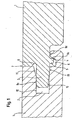
- Fig. 1 In the purely schematic Fig. 1 are designated by 1 two identical plates for interior work, wherein the one plate 1 has a groove 2 and the other plate 1, a spring 3, which extends into the groove 2 of the adjacent plate 1.
- the combination of tongue and groove secures the two plates 1 against forces which act transversely to the plane of the plate and strive to lift the plates from a supporting structure.
- the plates 1 are secured by the system to the support structure, not shown in Fig. 1.
- the surface of the panel 1 according to the invention which in FIG. 1 is actually the upper surface in FIG. 1, is the so-called visible surface act, which is intended to be directed to a room interior.
- This visible surface can be recognized by the fact that two adjacent plates on the contact surface 7 have no recognizable joint on this surface.
- the visible surface is accordingly formed by the surface shown as the lower surface.
- a contact surface 4 which is formed on the underside of the spring 3, the side wall of a retaining channel 6, so that a latching of the two plates 1 is achieved.
- the pad 8d provides for accurate positioning of the plates in a direction perpendicular to their surface.
- pad 8c provides for accurate positioning in a direction parallel to the surface.
- the distance, measured parallel to the surface of the plate, between the abutting edge 7 and the inner (as shown in FIG. 1, the right) edge of the rib 5 may be greater than the distance between the abutting edge 7 and the location of the contact point 8c in the retaining channel 6, so that here advantageously results in a press fit.
- the transition between the retaining channel 6 and the front edge of the associated groove cheek is designed rounded with a comparatively large radius such that a gentle, yet noticeable engagement of the rib 5 in the retaining channel 6 results.
- a glue-free connection of the two plates 1 is shown.
- a recess 9 above the spring 3 and below the upper contact surface 7, however, can serve as a glue receiving channel to receive excess glue, if the two plates 1 are to be permanently and joint-sealingly connected to each other by means of glue.
- the plates 1 can be moved by means of a pivoting movement and thereby locked.
- This z. B the left plate 1, of which the groove 2 is visible, initially laid.
- the second plate 1 is attached with its spring 3 obliquely to the side edge of the first plate 1 and while the spring 3 is inserted as far as possible in the groove 2. This is facilitated by the fact that the groove 2 has an upper edge 10, which rises towards the mouth of the groove 2 and in this way forms an insertion channel 11 which can be seen in particular from FIG.
- the spring 3 has an underside 12 which is beveled towards the free end of the spring 3, that is, rising, so that the right plate 1 can be inserted as far as possible into the groove 2 in its mentioned skew.
- This insertion movement is limited on the one hand by the contact of the spring 3 with the upper and lower boundary edges of the groove 2 and on the other hand by contact of the two plates 1 in the region of their upper contact surface 7.
- the subsequent pivoting of the right plate 1 causes the complete apparent from Fig. 1 immersion of the spring 3 in the groove 2 and the latching on the contact surface 4th
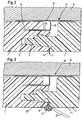
- a second embodiment is shown with a basically similar, namely latchable edge geometry of the two plates 1, but this geometry causes a less strong locking of the two plates 1.
- this geometry causes a less strong locking of the two plates 1.
- the groove-and-tongue design with the holding rib to be recognized on the side facing toward the supporting structure 15 of the spring 3 and a recess in the corresponding groove cheek is designed so that the two adjacent plates by a largely planar displacement can be connected to each other.
- the left to be recognized in Fig. 2 plate first in addition by means of the mounting bracket 16, mounted.
- the mounting bracket 16 of course, although not indicated in the drawing, is attached to the support structure. This can be accomplished, for example, advantageously by flat head screws are not projecting beyond the surfaces of the mounting bracket and thus not hinder the attachment of the plates according to the invention.
- the right to be recognized second plate 1 is attached laterally and placed on the support structure.
- the spring penetrates into the groove and causes by the interaction between the retaining rib and receiving channel for the retaining rib a snap-in connection.
- a seal between the two plates 1 is provided in the region of the contact surface 7.
- a sealing material 14 for example a silicone strip, which can already be injection-molded into one of the two plates 1 in favor of rapid laying, or which can be attached by the user to one of the plates 1 as desired.
- mounting brackets 16 consist of a base plate 17 which can be glued to the support structure 15, nailed, bolted or similar connected. From the base plate 17, a web 18 and from this an angled wing 19 extends into a groove 20 of the plate 1 shown on the left.
- the mounting bracket 16 has a comparatively wide base plate 17. This base plate can as well as the Rest of the mounting bracket 16 have a certain extent in a direction perpendicular to the plane of Fig. 2, so that a largely strip-shaped mounting bracket 16 is formed.
- the web 18 is substantially perpendicular, and the angled wings 19 in turn extends substantially perpendicular to the web 18 and thus substantially parallel to the base plate 17.
- the wing 19 may, however, also at a certain angle extend, so that in cooperation with a correspondingly aligned groove 20 in the plate 1, a certain clamping action is effected. It is shown purely schematically that behind the groove 20, the plate 1 does not extend to the web 18.
- the orientation of the two plates 1, z As a perpendicular orientation of elongated, rectangular plates 1, takes place in that the adjacent plates 1 are supported in the region of their contact surface 7 each other.
- either the plate shown on the right in Fig. 2 with its portion behind the spring 3 or the left plate 1 extends with its portion behind the groove 20 to the web 18 of the mounting bracket 16, so that thereby a Plant the plate 1 causes and the desired, z. B. vertical, alignment of the plate 1 is ensured and it is avoided that the plates 1 can tilt.
- Fig. 3 shows an embodiment similar to Fig. 2, but with no strip of sealing material 14 is provided, but a gluing of the two plates 1 by means of an adhesive 21.
- the recess 9 is filled here as a glue receiving channel with the adhesive 21.
- the tool 22 may, for. B. may be a knife with which the adhesive 21 preferably can then be removed after it is partially or largely tied off.
- the tool 22 may, for. As a spatula, with which the adhesive 21 can preferably be removed, as long as it is not tied but soft or pasty.
- a self-adhesive protective strip 23 is located on the surface along the longitudinal edges at the factory, which can be removed after removal of the adhesive surplus.
- Fig. 4 shows an example which does not fall under the scope of the claims, in which no latching of the plates is provided, but here the firm connection of the two plates 1 takes place only by means of adhesive 21. This extends far into the edge region of the plates 1 in and can for example already be factory-installed:
- a one-component adhesive may be provided, which is initially protected by means of a protective strip from setting. After removal of the protective strip, the two plates 1 can be connected to each other, so that the adhesive then set and the two plates 1 can connect to each other.
- a viewing groove 24 is provided in the region of the contact surface 7 in order to consciously achieve an optical structuring of the wall and ceiling cladding.
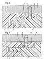
- Fig. 5 shows an embodiment similar to Fig. 2, in which, however, the plates 1 in the region of their contact surface 7 abut directly without a seal material therebetween.
- a press fit between the two plates 1 is effected, so that a firm contact of the two plates in the region of the contact surface 7 is ensured together.
- the plates of Figures 6 and 7 are substantially similar to those of Figures 4 and 5, with the example of Figure 7 not falling within the scope of the claims; the attachment of the plates, 1 on the support structure 15 is not by means of mounting brackets 16, but by means of screws 25, which - as a whole, the representations of Figs. 1 to 7 - are indicated purely schematically.
- the plates 1 each shown on the left have behind their groove 2 in each case one on the visible from the front edge of the plate groove lip 26, wherein the screws 25 extend through this groove lip 26.
- recesses 27 are provided in the groove lips 26, which can accommodate the screw head completely or, as in the illustrated embodiments, for the most part.
- recesses 27 may be provided as punctual depressions in the groove lips 26 so that z. B. the user hereby can be given an indication of at what points and what number of screws 25 he for attachment should use the plates 1.
- the recesses 27 may also be configured as a groove extending over the entire length of the groove lip 26, so that the user depending on the configuration of the support structure 15 can choose the appropriate attachment point.
- the plates 1 are shown purely schematically. Notwithstanding this purely schematic representation, they preferably consist of two or more different layers or materials: first, a core material, for example made of wood material, and second, a surface, for example, a laminate, wherein the laminate itself may in turn consist of layers of different materials , In particular, this surface can be structured in three dimensions, i. H. Have recesses and / or projections.
- the support structure 15 is shown in FIGS. 2 to 7 only purely schematically. It may be, for example, an aluminum profile, as it is customary for drywall in the trade. However, the support structure 15 can also be a wooden lath construction or existing ceiling or wall elements, such as masonry, roof beams or the like, which are to be clad with the panels 1.
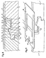
- Figs. 8 and 9 the structure is similar to that of the above-described embodiments.
- Tongue and groove are in this case in contrast to the previously described embodiments for a Einschwenkterrorism the applied to the left plate, designed in Fig. 8 right panel.
- directed to the room-side surface groove cheek is provided with a chamfer 28.
- the spring 3 is rounded on its side facing away from the space and has an inclined surface 30 on its side facing away from the space. This is located on a correspondingly inclined surface 32 of the remote from the interior of the groove cheek.
- a retaining channel 6 which has a rounded transition 34 to the front of the considered groove cheek.
- the protruding on the spring rib 5 engages snapping or clicking into engagement.
- the two plates can be joined together without joints.
- a particularly advantageous variant of the support of the two plates 1 already described in connection with FIG. 1 is realized at four defined points.
- the two first contact points 8a and 8b are located in the front region of the spring 3 on the side facing toward the visible side or away from the visible side of the spring.
- the third pad 8c is located at the point of contact between the protruding rib 5 and the rounded transition 34 of the retaining channel 6.
- the fourth pad 8d is not located between the retaining channel 6 and the leading edge 40 of the lower cheek. In this area, namely, a clearance for the section 19 of the mounting bracket 16 is required.
- a fourth contact point 8d in the contact region between the inclined surface 30 of the spring 3 and the inclined surface 32 of the side facing away from the groove cheek provided.
- the positional fixation in a direction perpendicular to the plate surfaces is made substantially by this contact point 8d.
- the position definition in a direction parallel to the surfaces of the plates 1 and a joint-free connection between the two plates 1 is achieved by the contact point 8c.
- the dimension between the contact point 8c and the visible upper edge of the plate 1 on the plate, which has the spring 3 a little larger than the corresponding dimension between the visible side upper edge of the plate, which has the groove, and the rounded transition 34th of the retaining channel, so that there is a press fit here.
- the four contact points 8a to 8d is a measure that is independent of the use of additional fasteners, for example in the form of the mounting bracket 16, and their advantages in any plates, for example, floor panels.
- a significant advantage is that the front end portion of the lower groove cheek can be used for additional fastening measures, for example by means of the bracket 16 shown or even by attachment by nails, when the fourth contact point 8d, which for a positional determination in a direction perpendicular to the Plate surfaces is provided on an inclined underside of the spring 3 or even a straight, but defined by the contact point 8b separate contact point on the underside of the spring is provided.
- the side facing away from the visible side Surface of the spring 3 at the transition between the region which is substantially parallel to the plate surface and the contact point 8b, and the inclined surface 30 has an at least slight recess 52 which separates these two contact areas from each other.
- this does not necessarily add the kink on the side of the spring 3 facing away from the visible side to the corresponding kink on the side of the respective groove cheek. Rather, the contact must only take place at the contact point 8b and between the two inclined surfaces 30, 32 in order to fix the two panels in a defined position relative to one another.
- FIG. 8 of the right plate takes place only after, as shown in FIG. 8, the left plate was fastened by means of one or more mounting brackets 16 to the substrate.
- This mounting bracket substantially corresponds to the mounting brackets described above.
- a special feature of the embodiment of Fig. 8, however, is that the plate according to the invention has on the side which has the groove, no additional groove (20, see Fig. 2) for receiving the portion 19 of the mounting bracket. Rather, the height of the facing away from the interior of the groove groove cheek is matched with the free space 36 on the side facing away from the space (right) spring plate, that there is a free space or recess 38 for the portion 19 of the mounting bracket 16.
- a suitable clearance 44 remains, in which the web 18 of the mounting bracket are received, the portion 19 with the base plate 17 of the mounting bracket 16 connects.
- those additional fastening means namely the free spaces 38, 44 are formed in their connected state in the connecting region of two plates.
- Fig. 9 the embodiment of Fig. 8 is shown in a perspective view. This results in addition to the dimension of the mounting bracket 16 in the direction of the considered connecting edges of two plates 1. This dimension is relatively short, so that usually several such staples are used in the course of an edge.
- the bracket can be attached to a support structure, for example by screws, so that subsequently in the manner described above, a further plate, as shown in FIG. 9, the left plate can be mounted.
- a subsequently laid plate, as shown in FIG. 9, the left plate, in the direction of the connecting edges is displaceable.
- the free space 38 is selected such that the fastening clips used do not hinder such a displacement.
- another third plate on the third and fourth sides (the previous embodiments related only to the first and second sides) can be connected.
- the medium larger opening to be detected is designed as a slot, so that, if appropriate, the bracket itself can shift a little with respect to the supporting structure to which it is attached.
- the stated advantages can be achieved by the support or substructure itself is designed to be movable.
- the connection between a plurality of panels according to the invention and the supporting or substructure would be rigid, the "clad surface but" work "characterized in that the support or substructure, in particular the battens or beams thereof, are slidably mounted with respect to a fixed part of the building.
- connection on the third and fourth side is shown in the further figures.
- Fig. 10 similarities with the embodiments of FIGS. 2, 3, 5 and 6, since the connection is made essentially by a linear sliding movement. In particular, reaches a rib 6, which on the one Side of the spring 5 is directed, which is directed away from the space, latching or -schnappend into engagement with a retaining channel 6, which is formed on that, the groove 2 delimiting groove cheek, which is also directed away from the space inside.
- a special feature of the connection shown in Fig. 10 is that the spring 3 is comparatively short and protrudes into the groove 2 only to a small extent.
- the sliding path required for the latching is essentially determined by the distance A between the outer edge of the spring 3 and the front edge of the groove cheek directed to the space, since in the pivoting of the above-mentioned third plate, the leading edge of the spring 3 at the front edge of the Nutwange an already laid second plate must pass. Only when this has been done, the third plate can be moved in the left-right direction shown in FIG. 10 in order to assume the mounting state shown in Fig. 10. In the embodiment of Fig. 10, the length of the spring 3 is shortened substantially to that degree which is required for a reliable support of the spring 3 in the groove 2.
- FIG. 11 differs from the embodiment of FIG. 10 in that it faces away from the space according to FIG 11 upper groove cheek continues to extend as the room-side groove cheek, and that in this area the retaining channel 6 is provided for receiving the rib 5.
- This is preferred for certain applications and, moreover, achieves the same advantages as those described above in connection with the embodiment of FIG. 10.
- FIG. 12 differs from that of FIG. 11 in that on the one hand both the rib 5 and the boundaries of the retaining channel 6 are somewhat hook-shaped.
- the groove 2, which serves to receive the spring 3 a depression 48 connects, in the case shown a smaller width (according to FIG. 12, the dimension from top to bottom) than the Groove 2.
- the recess 48 may at least partially have the same width as the groove 2 and otherwise designed to be arbitrary. Due to this longer design, the groove cheek can be provided to a greater extent with flexibility and possible spring travel, which leads to particularly good deflection properties that are required to the rib 5 to let pass at the boundaries of the holding channel 6, so that the connection is made.
- FIG. 14 finally, an embodiment is shown in which a newly laid, as shown in FIG. 14 left plate 1 by movement with an already laid, as shown in FIG. 14 right plate 1 is engaged, which is substantially perpendicular to the plate surfaces ,
- a plate to be relocated is attached at its first or second side obliquely to the already laid first plate and subsequently pivoted down, for example according to the connection shown in FIGS. 8 and 9.
- the attachment takes place in such a way that the shown, from the plate surface largely perpendicularly directed away spring 3 is aligned approximately with the groove 2 open to the top of the plate.
- spring 3 When lowering the spring 3 then enters the position shown in Fig. 14 and is held detent.
Applications Claiming Priority (3)
| Application Number | Priority Date | Filing Date | Title |
|---|---|---|---|
| DE10064280 | 2000-12-22 | ||
| DE10064280A DE10064280C1 (de) | 2000-12-22 | 2000-12-22 | Platte für den Innenausbau sowie Verfahren zum Erstellen von neuen Wänden eines Raumes oder zur Verkleidung von vorhandenen Flächen eines Raumes |
| PCT/EP2001/015144 WO2002052113A2 (de) | 2000-12-22 | 2001-12-20 | Wand- oder verkleidungsplatte für den innenausbau und trockenbau |
Publications (2)
| Publication Number | Publication Date |
|---|---|
| EP1343943A2 EP1343943A2 (de) | 2003-09-17 |
| EP1343943B1 true EP1343943B1 (de) | 2006-02-22 |
Family
ID=7668447
Family Applications (1)
| Application Number | Title | Priority Date | Filing Date |
|---|---|---|---|
| EP01988053A Expired - Lifetime EP1343943B1 (de) | 2000-12-22 | 2001-12-20 | Platte für den innenausbau und trockenbau sowie verfahren zum erstellen von neuen wänden eines raumes oder zur verkleidung von vorhandenen flächen eines raumes |
Country Status (14)
| Country | Link |
|---|---|
| US (1) | US20060010820A1 (cs) |
| EP (1) | EP1343943B1 (cs) |
| JP (1) | JP2004517234A (cs) |
| KR (1) | KR20030081363A (cs) |
| CN (1) | CN1531617A (cs) |
| AT (1) | ATE318354T1 (cs) |
| AU (1) | AU2002240860B2 (cs) |
| CA (1) | CA2432891A1 (cs) |
| CZ (1) | CZ20031694A3 (cs) |
| DE (2) | DE10064280C1 (cs) |
| NO (1) | NO20032869L (cs) |
| RU (1) | RU2003122332A (cs) |
| SK (1) | SK7892003A3 (cs) |
| WO (1) | WO2002052113A2 (cs) |
Cited By (6)
| Publication number | Priority date | Publication date | Assignee | Title |
|---|---|---|---|---|
| CN102041892A (zh) * | 2010-10-20 | 2011-05-04 | 向广宏 | 地板龙骨 |
| DE202016106285U1 (de) | 2016-06-29 | 2017-02-16 | SWISS KRONO Tec AG | Klammersystem für Paneele |
| WO2019003100A1 (en) * | 2017-06-27 | 2019-01-03 | Flooring Industries Limited, Sarl | WALL OR CEILING PANEL AND WALL OR CEILING ASSEMBLY |
| BE1025342B1 (nl) * | 2017-06-27 | 2019-02-04 | Flooring Industries Limited, Sarl | Wand- of plafondpaneel en wand- of plafondinrichting |
| US10323670B2 (en) | 2008-12-17 | 2019-06-18 | Unilin, Bvba | Composed element, multi-layered board and panel-shaped element for forming this composed element |
| US10982700B2 (en) | 2010-06-03 | 2021-04-20 | Unilin Bv | Composed element and corner connection applied herewith |
Families Citing this family (67)
| Publication number | Priority date | Publication date | Assignee | Title |
|---|---|---|---|---|
| DE10233105B4 (de) * | 2002-07-20 | 2007-01-18 | Werzalit Ag + Co. Kg | Profilelement mit Verbindungsteilen für mechanische Steckverbindungen und damit geschaffener Profilelementenverbund |
| DE50207813D1 (de) | 2002-11-26 | 2006-09-21 | Huelsta Werke Huels Kg | Kombination einer Platte oder eines Paneels und zumindest einer Befestigungsanordnung sowie Verfahren zur Befestigung einer Platte oder eines Paneels |
| SE0300642D0 (sv) | 2003-03-11 | 2003-03-11 | Pergo Europ Ab | Process for sealing a joint |
| DE20314719U1 (de) | 2003-09-23 | 2005-02-10 | Hülsta-Werke Hüls Gmbh & Co. Kg | Bodenplatte |
| DE102004061437B4 (de) * | 2004-12-17 | 2007-05-03 | Dieter Reif | Befestigungsklammer zur Verbindung von Holzbauteilen |
| PL1711353T3 (pl) | 2004-12-23 | 2010-05-31 | Flooring Ind Ltd | Laminowany panel podłogowy |
| EP1726735A1 (de) * | 2005-05-23 | 2006-11-29 | MBS Spanplattenbeschichtungs GmbH | Wandverkleidungssystem |
| DE102006008686A1 (de) * | 2006-02-24 | 2007-09-06 | Deutsche Amphibolin-Werke Von Robert Murjahn Stiftung & Co Kg | Verkleidungssystem |
| NL1031727C2 (nl) * | 2006-05-01 | 2007-11-02 | Frank Van Roy Beheer B V | Systeem voor het bekleden van een bekledingsvlak omvattende bekledingselementen en beugelorganen. |
| US8065851B2 (en) | 2006-08-25 | 2011-11-29 | Huber Engineered Woods Llc | Self-spacing wood composite panels |
| EP2076639A1 (de) * | 2006-10-11 | 2009-07-08 | Hülsta-Werke Hüls GmbH & CO. KG | Paneel und belag aus einer mehrzahl von paneelen |
| US20110223372A1 (en) * | 2006-10-16 | 2011-09-15 | Csp Systems, Inc. | Non-Planar Composite Structural Panel |
| US20080086965A1 (en) * | 2006-10-16 | 2008-04-17 | Metz Timothy W | Composite structural panel |
| DE102006060455B4 (de) * | 2006-10-27 | 2012-10-04 | Hülsta-Werke Hüls Gmbh & Co. Kg | Befestigungssystem zur Rand- und/oder Eckbefestigung von wenigstens einem Paneel |
| DE102007007832A1 (de) * | 2007-02-16 | 2008-11-20 | Kaindl Flooring Gmbh | Verkleidungspaneel |
| US7644556B2 (en) * | 2007-11-15 | 2010-01-12 | Correct Building Products, L.L.C. | Planking system and method |
| CA2623707A1 (en) * | 2008-03-07 | 2009-09-07 | Pierre Trudel | Tongue and groove profile to ease desassembly of floorboards |
| IT1391034B1 (it) * | 2008-07-17 | 2011-10-27 | Skema S R L | Pannello per rivestire superfici e metodo per fissare uno o piu' pannelli di rivestimento ad una superficie |
| ITUD20090024A1 (it) * | 2009-02-04 | 2010-08-05 | Patt S P A | Parete di rivestimento, di tipo modulare, e pannello per la realizzazione di tale parete |
| USD656245S1 (en) * | 2009-04-16 | 2012-03-20 | Rene St-Cyr (1996) Inc. | Floor plank |
| US8365499B2 (en) | 2009-09-04 | 2013-02-05 | Valinge Innovation Ab | Resilient floor |
| US11725395B2 (en) | 2009-09-04 | 2023-08-15 | Välinge Innovation AB | Resilient floor |
| US8833028B2 (en) | 2010-01-11 | 2014-09-16 | Valinge Innovation Ab | Floor covering with interlocking design |
| EP2345545B1 (en) * | 2010-01-13 | 2015-03-04 | Kronoplus Technical AG | Direct printed lightweight panel |
| CN101832005A (zh) * | 2010-05-06 | 2010-09-15 | 姚福才 | 免粘墙体表面装饰砖 |
| BE1019891A5 (nl) | 2011-03-28 | 2013-02-05 | Unilin Bvba | Samengesteld element en rugwandconstructie hierbij toegepast. |
| DE102011001843A1 (de) | 2011-04-06 | 2012-10-11 | Guido Schulte | Flächenverkleidung von Wand- oder Deckenbereichen sowie Verfahren zur Verkleidung von Wand- oder Deckenbereich |
| DE102011102795A1 (de) * | 2011-05-27 | 2012-11-29 | Michael Weinig Aktiengesellschaft | Verfahren zur Herstellung von Endprodukten, insbesondere von Wandelementen, Brettsperrholzteilen, Leisten und dergleichen, aus Holz, Holzwerkstoffen, Kunststoff und dergleichen |
| DE102011050762A1 (de) | 2011-05-31 | 2012-12-06 | Guido Schulte | Decken- oder Wandpaneel sowie Verfahren zur Verkleidung eines Decken- oder Wandbereichs |
| WO2013044377A1 (en) * | 2011-09-28 | 2013-04-04 | Distribution Duroy Inc. | Covering panel and method for assembling a plurality of same |
| JP2013249601A (ja) * | 2012-05-30 | 2013-12-12 | Nippon Steel & Sumikin Coated Sheet Corp | 無機質内装材及び無機質内装材の接合構造 |
| SE536680C2 (sv) * | 2012-09-18 | 2014-05-20 | Oneday Wall Ab | Väggkonstruktion med reglar och monteringsmetod |
| DE102012111019A1 (de) | 2012-11-15 | 2014-05-15 | Guido Schulte | Paneelsystem für die Montage an Wänden, Decken oder Böden |
| US9206827B2 (en) | 2012-11-20 | 2015-12-08 | Avery Dennison Corporation | Wall mount organization system |
| DE102013204028A1 (de) * | 2013-03-08 | 2014-09-11 | Homag Holzbearbeitungssysteme Gmbh | Verarbeitungsstation zum Anbringen eines Profilelements |
| KR101368321B1 (ko) * | 2013-03-20 | 2014-02-27 | (주) 제이디피이에스 | 산업용 안전매트 |
| ES2673421T3 (es) | 2013-03-25 | 2018-06-21 | Välinge Innovation AB | Tableros de suelo provistos de un sistema de bloqueo mecánico y método para producir tal sistema de bloqueo |
| EP3567184B1 (en) | 2014-08-29 | 2022-12-28 | Välinge Innovation AB | Vertical joint system for a surface covering panel |
| GB2536697A (en) * | 2015-03-26 | 2016-09-28 | Bpb United Kingdom Ltd | Building element |
| US10246882B2 (en) | 2015-11-10 | 2019-04-02 | Kong Taing | Structural wall panel system |
| CN108368704A (zh) * | 2015-12-17 | 2018-08-03 | 瓦林格创新股份有限公司 | 用于制造用于镶板的机械锁定系统的方法 |
| US10501943B1 (en) * | 2016-02-19 | 2019-12-10 | Custom Finish Wood Flooring Llc | Systems and methods for installing flooring |
| MX2019003403A (es) | 2016-09-30 | 2019-05-30 | Vaelinge Innovation Ab | Conjunto de paneles armados mediante desplazamiento vertical y asegurados unos con otros en la direccion vertical y horizontal. |
| CN106760240A (zh) * | 2016-12-23 | 2017-05-31 | 海盐广发新能源有限公司 | 一种屋顶板及其连接方法 |
| CN106760354A (zh) * | 2017-02-08 | 2017-05-31 | 黄帆 | 隐藏式墙体板连接扣件及其快速铺设墙体板的方法 |
| DE112017007688T5 (de) | 2017-06-12 | 2020-03-12 | Knauf Gips Kg | Bauplatte, vorzugsweise für eine Abdeckung im Inneren eines Gebäudes |
| US20190013002A1 (en) * | 2017-07-06 | 2019-01-10 | Westhill Innovation Inc. | Structural laminate sound barrier |
| CN207620259U (zh) * | 2017-07-19 | 2018-07-17 | 上海协承昌化工有限公司 | 一种板材及其装饰面板 |
| CN107401262A (zh) * | 2017-08-03 | 2017-11-28 | 绵阳行之智汇知识产权服务有限公司 | 一种采用墙板卡扣机械结构的墙板安装结构 |
| CN107558686A (zh) * | 2017-09-19 | 2018-01-09 | 浙江佳中木业有限公司 | 一种用于制冷供热的地板结构 |
| EP3737802B1 (en) | 2018-01-09 | 2023-05-10 | Välinge Innovation AB | Set of panels |
| EP3536874A1 (en) * | 2018-03-05 | 2019-09-11 | Tarkett GDL S.A. | Set of tiles adapted to cover a surface such as a floor |
| CN110385762A (zh) * | 2018-04-20 | 2019-10-29 | 南昌茗竹居家居有限公司 | 一种用于家具生产组装的卯榫结构 |
| FR3082542B1 (fr) * | 2018-06-19 | 2021-01-01 | Saint Gobain Isover | Procede de realisation d'un parement |
| PT3670783T (pt) * | 2018-12-21 | 2021-06-30 | SWISS KRONO Tec AG | Grampo de montagem para montagem flutuante de painéis de parede e de teto |
| EP3972837A4 (en) * | 2019-05-20 | 2023-06-28 | Shaw Industries Group, Inc. | Cellulose based composite planks |
| CN110284606A (zh) * | 2019-07-25 | 2019-09-27 | 苏州嘉谷环保科技有限公司 | 一种防渗水装配式房屋及防渗水方法 |
| BE1028044B1 (nl) | 2020-02-10 | 2021-09-07 | Unilin | Wand- of plafondpaneel en wand- of plafondbekleding |
| NO346085B1 (en) | 2020-09-08 | 2022-02-07 | Forestia As | A ceiling board, a method for mounting a plurality of same, and a kit of tools for use in the method |
| CN112172289A (zh) * | 2020-10-26 | 2021-01-05 | 章鸽子 | 一种高强度防水保温隔热屋面装饰板 |
| EP4256149A1 (en) | 2020-12-01 | 2023-10-11 | Flooring Industries Limited, SARL | Wall or ceiling panel assembly, a set of panels for forming such assembly and a wall or ceiling obtained therewith |
| USD971005S1 (en) * | 2021-03-19 | 2022-11-29 | Välinge Innovation AB | Clip for wall panels |
| NL2028616B1 (en) * | 2021-07-02 | 2023-01-10 | I4F Licensing Nv | Wall panel for forming a wall covering with multiple panels |
| US11814838B2 (en) | 2021-07-02 | 2023-11-14 | I4F Licensing Nv | Wall panel for forming a wall covering with multiple panels |
| CN113931342B (zh) * | 2021-10-27 | 2023-02-24 | 佛山市粤泰建筑劳务有限公司 | 一种自带防水机构的预制装配式墙体拼接结构 |
| CN113982214B (zh) * | 2021-11-25 | 2023-02-24 | 无锡市中旭环保设备有限公司 | 一种室内防火装饰墙体及其制备方法 |
| WO2023233251A1 (en) | 2022-06-01 | 2023-12-07 | Flooring Industries Limited, Sarl | Wall or ceiling panel, connection member and assembly of a wall or ceiling panel and a connection member |
Family Cites Families (12)
| Publication number | Priority date | Publication date | Assignee | Title |
|---|---|---|---|---|
| US1898364A (en) * | 1930-02-24 | 1933-02-21 | George S Gynn | Flooring construction |
| DE2828769A1 (de) * | 1978-06-30 | 1980-01-03 | Oltmanns Heinrich Fa | Kastenfoermige bautafel aus extrudiertem kunststoff |
| AU8920582A (en) * | 1981-10-28 | 1983-05-05 | Sealey, B.D. | Interlocking panelling |
| US4769963A (en) * | 1987-07-09 | 1988-09-13 | Structural Panels, Inc. | Bonded panel interlock device |
| DE4337743C5 (de) * | 1993-11-05 | 2006-04-06 | hülsta-werke Hüls GmbH & Co KG | Paneelelement zur Wand- und Deckenverkleidung |
| DE19503948A1 (de) * | 1995-02-07 | 1996-08-08 | Bub Frank Martin | Bauelement zur Verkleidung von Flächen mit Oberflächenelementen |
| DE29719986U1 (de) | 1997-11-11 | 1998-02-12 | Huelsta Werke Huels Kg | Paneelelement zur paneelklammerlosen Befestigung |
| JPH11350706A (ja) * | 1998-06-05 | 1999-12-21 | Nisshin Steel Co Ltd | 金属パネル |
| BE1013148A3 (nl) | 1999-11-23 | 2001-10-02 | Unilin Beheer Bv | Bekleding alsmede elementen voor het vormen van dergelijke bekleding. |
| DE10001076C1 (de) * | 2000-01-13 | 2001-10-04 | Huelsta Werke Huels Kg | Paneelelement |
| EP1120515A1 (en) | 2000-01-27 | 2001-08-01 | Triax N.V. | A combined set comprising a locking member and at least two building panels |
| DE20017114U1 (de) | 2000-10-04 | 2000-12-21 | Dammers Dirk | Paneelelement |
-
2000
- 2000-12-22 DE DE10064280A patent/DE10064280C1/de not_active Expired - Lifetime
-
2001
- 2001-12-20 US US10/451,547 patent/US20060010820A1/en not_active Abandoned
- 2001-12-20 KR KR10-2003-7008543A patent/KR20030081363A/ko not_active Application Discontinuation
- 2001-12-20 WO PCT/EP2001/015144 patent/WO2002052113A2/de active IP Right Grant
- 2001-12-20 AU AU2002240860A patent/AU2002240860B2/en not_active Expired - Fee Related
- 2001-12-20 JP JP2002553579A patent/JP2004517234A/ja not_active Withdrawn
- 2001-12-20 EP EP01988053A patent/EP1343943B1/de not_active Expired - Lifetime
- 2001-12-20 SK SK789-2003A patent/SK7892003A3/sk unknown
- 2001-12-20 CA CA002432891A patent/CA2432891A1/en not_active Abandoned
- 2001-12-20 RU RU2003122332/03A patent/RU2003122332A/ru not_active Application Discontinuation
- 2001-12-20 AT AT01988053T patent/ATE318354T1/de not_active IP Right Cessation
- 2001-12-20 CN CNA018228151A patent/CN1531617A/zh active Pending
- 2001-12-20 DE DE50109019T patent/DE50109019D1/de not_active Expired - Lifetime
- 2001-12-20 CZ CZ20031694A patent/CZ20031694A3/cs unknown
-
2003
- 2003-06-20 NO NO20032869A patent/NO20032869L/no unknown
Cited By (14)
| Publication number | Priority date | Publication date | Assignee | Title |
|---|---|---|---|---|
| US11085475B2 (en) | 2008-12-17 | 2021-08-10 | Flooring Industries Limited, Sarl | Composed element, multi-layered board and panel-shaped element for forming this composed element |
| US11788568B2 (en) | 2008-12-17 | 2023-10-17 | Flooring Industries Limited Sarl | Composed element, multi-layered board and panel-shaped element for forming this composed element |
| US10323670B2 (en) | 2008-12-17 | 2019-06-18 | Unilin, Bvba | Composed element, multi-layered board and panel-shaped element for forming this composed element |
| US10731689B2 (en) | 2008-12-17 | 2020-08-04 | Unilin, Bvba | Composed element, multi-layered board and panel-shaped element for forming this composed element |
| US10982700B2 (en) | 2010-06-03 | 2021-04-20 | Unilin Bv | Composed element and corner connection applied herewith |
| CN102041892A (zh) * | 2010-10-20 | 2011-05-04 | 向广宏 | 地板龙骨 |
| DE202016106285U1 (de) | 2016-06-29 | 2017-02-16 | SWISS KRONO Tec AG | Klammersystem für Paneele |
| BE1025342B1 (nl) * | 2017-06-27 | 2019-02-04 | Flooring Industries Limited, Sarl | Wand- of plafondpaneel en wand- of plafondinrichting |
| US11072929B2 (en) | 2017-06-27 | 2021-07-27 | Flooring Industries Limited, Sarl | Wall or ceiling panel and wall or ceiling assembly |
| EP3964670A1 (en) * | 2017-06-27 | 2022-03-09 | Flooring Industries Limited, SARL | Wall or ceiling panel and wall or ceiling assembly |
| EP3964669A1 (en) * | 2017-06-27 | 2022-03-09 | Flooring Industries Limited, SARL | Wall or ceiling panel and wall or ceiling assembly |
| US11788300B2 (en) | 2017-06-27 | 2023-10-17 | Flooring Industries Limited, Sarl | Wall or ceiling panel and wall or ceiling assembly |
| WO2019003100A1 (en) * | 2017-06-27 | 2019-01-03 | Flooring Industries Limited, Sarl | WALL OR CEILING PANEL AND WALL OR CEILING ASSEMBLY |
| US11939777B2 (en) | 2017-06-27 | 2024-03-26 | Unilin, Bv | Wall or ceiling panel and wall or ceiling assembly |
Also Published As
| Publication number | Publication date |
|---|---|
| EP1343943A2 (de) | 2003-09-17 |
| KR20030081363A (ko) | 2003-10-17 |
| WO2002052113A3 (de) | 2003-01-30 |
| SK7892003A3 (en) | 2004-06-08 |
| DE10064280C1 (de) | 2002-10-10 |
| AU2002240860B2 (en) | 2006-04-27 |
| CZ20031694A3 (cs) | 2003-11-12 |
| CA2432891A1 (en) | 2002-07-04 |
| JP2004517234A (ja) | 2004-06-10 |
| CN1531617A (zh) | 2004-09-22 |
| DE50109019D1 (de) | 2006-04-27 |
| NO20032869L (no) | 2003-08-22 |
| RU2003122332A (ru) | 2004-12-10 |
| WO2002052113A2 (de) | 2002-07-04 |
| ATE318354T1 (de) | 2006-03-15 |
| NO20032869D0 (no) | 2003-06-20 |
| US20060010820A1 (en) | 2006-01-19 |
Similar Documents
| Publication | Publication Date | Title |
|---|---|---|
| EP1343943B1 (de) | Platte für den innenausbau und trockenbau sowie verfahren zum erstellen von neuen wänden eines raumes oder zur verkleidung von vorhandenen flächen eines raumes | |
| DE60106543T2 (de) | Mehrteiliges Fussbodensystem, Paneelverbinder mit Dichtung | |
| EP1561892B1 (de) | Verkleidungsanordnung für Gebäudeaussen- und/oder Innenflächen sowie für Aussen- und/oder Innenflächen von Türen, Fenstern und anderen Funktionsflächen von Gebäuden | |
| DE10118826A1 (de) | Profilleiste | |
| DE19962812A1 (de) | Verfahren und Vorrichtung zum Schließen von Fugen | |
| DE102007048801A1 (de) | Dämmelement | |
| EP3112545B1 (de) | Akustikpaneel | |
| EP1088945A2 (de) | Fassadendämmelement | |
| DE19538226A1 (de) | Plattenförmiges Dämmelement aus Mineralwolle | |
| EP1317592B1 (de) | Verfahren und System zum lösbaren Befestigen eines flächigen Bauteils auf einem Untergrund, insbesondere einer Fliese an einer Wand oder auf einem Boden, sowie Formfolie hierfür | |
| DE19640633A1 (de) | Verfahren zur Befestigung von Strukturelementen, entsprechendes Strukturelement und Halteelement hierfür | |
| DE19502733A1 (de) | Platten für Gebäudeinnenräume | |
| DE10237076A1 (de) | Plattenverband aus Platten aus einem Gipswerkstoff und Verfahren zum Herstellen eines Plattenverbandes | |
| DE19941284A1 (de) | Belagsystem sowie Verfahren zur Verlegung desselben | |
| EP1867796B1 (de) | Verbundplatte für den Innenausbau | |
| EP3293323A1 (de) | Montagesystem für fussbodensockel oder fussbodenleiste | |
| DE7725149U1 (de) | Keramisches bauelement | |
| DE10051887B4 (de) | Verfahren und System zum lösbaren Befestigen eines flächigen Bauteils auf einem Untergrund, insbesondere einer Fliese an einer Wand oder auf einem Boden | |
| DE19860202B4 (de) | Plattenverkleidung | |
| EP0154913A2 (de) | Wandanschlussprofil | |
| DE202006001545U1 (de) | Bausatz zur Erstellung eines Fußbodenbelags aus platten- oder stabartigen Elementen | |
| EP1484195A2 (de) | Verkleidungsplatte mit einem Farbstreifen | |
| EP1726735A1 (de) | Wandverkleidungssystem | |
| EP0671517B1 (de) | Vorgefertigtes Bauelement, Verfahren zur Herstellung und Verwendung desselben | |
| DE3244511A1 (de) | Verfahren zum verkleiden von fassaden und fassadenelement zur durchfuehrung des verfahrens |
Legal Events
| Date | Code | Title | Description |
|---|---|---|---|
| PUAI | Public reference made under article 153(3) epc to a published international application that has entered the european phase |
Free format text: ORIGINAL CODE: 0009012 |
|
| 17P | Request for examination filed |
Effective date: 20030613 |
|
| AK | Designated contracting states |
Kind code of ref document: A2 Designated state(s): AT BE CH CY DE DK ES FI FR GB GR IE IT LI LU MC NL PT SE TR |
|
| AX | Request for extension of the european patent |
Extension state: AL LT LV MK RO SI |
|
| RAP1 | Party data changed (applicant data changed or rights of an application transferred) |
Owner name: FIRMA HUELSTA-WERKE HUELS GMBH & CO. KG |
|
| RAP1 | Party data changed (applicant data changed or rights of an application transferred) |
Owner name: HUELSTA-WERKE HUELS GMBH & CO. KG |
|
| GRAP | Despatch of communication of intention to grant a patent |
Free format text: ORIGINAL CODE: EPIDOSNIGR1 |
|
| GRAS | Grant fee paid |
Free format text: ORIGINAL CODE: EPIDOSNIGR3 |
|
| GRAA | (expected) grant |
Free format text: ORIGINAL CODE: 0009210 |
|
| AK | Designated contracting states |
Kind code of ref document: B1 Designated state(s): AT BE CH CY DE DK ES FI FR GB GR IE IT LI LU MC NL PT SE TR |
|
| AX | Request for extension of the european patent |
Extension state: SI |
|
| PG25 | Lapsed in a contracting state [announced via postgrant information from national office to epo] |
Ref country code: IT Free format text: LAPSE BECAUSE OF FAILURE TO SUBMIT A TRANSLATION OF THE DESCRIPTION OR TO PAY THE FEE WITHIN THE PRESCRIBED TIME-LIMIT;WARNING: LAPSES OF ITALIAN PATENTS WITH EFFECTIVE DATE BEFORE 2007 MAY HAVE OCCURRED AT ANY TIME BEFORE 2007. THE CORRECT EFFECTIVE DATE MAY BE DIFFERENT FROM THE ONE RECORDED. Effective date: 20060222 Ref country code: GB Free format text: LAPSE BECAUSE OF FAILURE TO SUBMIT A TRANSLATION OF THE DESCRIPTION OR TO PAY THE FEE WITHIN THE PRESCRIBED TIME-LIMIT Effective date: 20060222 Ref country code: FI Free format text: LAPSE BECAUSE OF FAILURE TO SUBMIT A TRANSLATION OF THE DESCRIPTION OR TO PAY THE FEE WITHIN THE PRESCRIBED TIME-LIMIT Effective date: 20060222 Ref country code: IE Free format text: LAPSE BECAUSE OF FAILURE TO SUBMIT A TRANSLATION OF THE DESCRIPTION OR TO PAY THE FEE WITHIN THE PRESCRIBED TIME-LIMIT Effective date: 20060222 Ref country code: NL Free format text: LAPSE BECAUSE OF FAILURE TO SUBMIT A TRANSLATION OF THE DESCRIPTION OR TO PAY THE FEE WITHIN THE PRESCRIBED TIME-LIMIT Effective date: 20060222 |
|
| REG | Reference to a national code |
Ref country code: GB Ref legal event code: FG4D Free format text: NOT ENGLISH |
|
| REG | Reference to a national code |
Ref country code: CH Ref legal event code: EP |
|
| REG | Reference to a national code |
Ref country code: IE Ref legal event code: FG4D Free format text: LANGUAGE OF EP DOCUMENT: GERMAN |
|
| REF | Corresponds to: |
Ref document number: 50109019 Country of ref document: DE Date of ref document: 20060427 Kind code of ref document: P |
|
| PG25 | Lapsed in a contracting state [announced via postgrant information from national office to epo] |
Ref country code: DK Free format text: LAPSE BECAUSE OF FAILURE TO SUBMIT A TRANSLATION OF THE DESCRIPTION OR TO PAY THE FEE WITHIN THE PRESCRIBED TIME-LIMIT Effective date: 20060522 Ref country code: SE Free format text: LAPSE BECAUSE OF FAILURE TO SUBMIT A TRANSLATION OF THE DESCRIPTION OR TO PAY THE FEE WITHIN THE PRESCRIBED TIME-LIMIT Effective date: 20060522 |
|
| PG25 | Lapsed in a contracting state [announced via postgrant information from national office to epo] |
Ref country code: ES Free format text: LAPSE BECAUSE OF FAILURE TO SUBMIT A TRANSLATION OF THE DESCRIPTION OR TO PAY THE FEE WITHIN THE PRESCRIBED TIME-LIMIT Effective date: 20060602 |
|
| PG25 | Lapsed in a contracting state [announced via postgrant information from national office to epo] |
Ref country code: PT Free format text: LAPSE BECAUSE OF FAILURE TO SUBMIT A TRANSLATION OF THE DESCRIPTION OR TO PAY THE FEE WITHIN THE PRESCRIBED TIME-LIMIT Effective date: 20060724 |
|
| NLV1 | Nl: lapsed or annulled due to failure to fulfill the requirements of art. 29p and 29m of the patents act | ||
| GBV | Gb: ep patent (uk) treated as always having been void in accordance with gb section 77(7)/1977 [no translation filed] |
Effective date: 20060222 |
|
| REG | Reference to a national code |
Ref country code: IE Ref legal event code: FD4D |
|
| PLBE | No opposition filed within time limit |
Free format text: ORIGINAL CODE: 0009261 |
|
| STAA | Information on the status of an ep patent application or granted ep patent |
Free format text: STATUS: NO OPPOSITION FILED WITHIN TIME LIMIT |
|
| PG25 | Lapsed in a contracting state [announced via postgrant information from national office to epo] |
Ref country code: LI Free format text: LAPSE BECAUSE OF NON-PAYMENT OF DUE FEES Effective date: 20061231 Ref country code: CH Free format text: LAPSE BECAUSE OF NON-PAYMENT OF DUE FEES Effective date: 20061231 Ref country code: MC Free format text: LAPSE BECAUSE OF NON-PAYMENT OF DUE FEES Effective date: 20061231 Ref country code: BE Free format text: LAPSE BECAUSE OF NON-PAYMENT OF DUE FEES Effective date: 20061231 |
|
| 26N | No opposition filed |
Effective date: 20061123 |
|
| EN | Fr: translation not filed | ||
| REG | Reference to a national code |
Ref country code: CH Ref legal event code: PL |
|
| BERE | Be: lapsed |
Owner name: HULSTA-WERKE HULS G.M.B.H. & CO. KG Effective date: 20061231 |
|
| PG25 | Lapsed in a contracting state [announced via postgrant information from national office to epo] |
Ref country code: AT Free format text: LAPSE BECAUSE OF NON-PAYMENT OF DUE FEES Effective date: 20061220 |
|
| PG25 | Lapsed in a contracting state [announced via postgrant information from national office to epo] |
Ref country code: GR Free format text: LAPSE BECAUSE OF FAILURE TO SUBMIT A TRANSLATION OF THE DESCRIPTION OR TO PAY THE FEE WITHIN THE PRESCRIBED TIME-LIMIT Effective date: 20060523 Ref country code: FR Free format text: LAPSE BECAUSE OF FAILURE TO SUBMIT A TRANSLATION OF THE DESCRIPTION OR TO PAY THE FEE WITHIN THE PRESCRIBED TIME-LIMIT Effective date: 20070420 |
|
| PG25 | Lapsed in a contracting state [announced via postgrant information from national office to epo] |
Ref country code: TR Free format text: LAPSE BECAUSE OF FAILURE TO SUBMIT A TRANSLATION OF THE DESCRIPTION OR TO PAY THE FEE WITHIN THE PRESCRIBED TIME-LIMIT Effective date: 20060222 Ref country code: LU Free format text: LAPSE BECAUSE OF NON-PAYMENT OF DUE FEES Effective date: 20061220 |
|
| PG25 | Lapsed in a contracting state [announced via postgrant information from national office to epo] |
Ref country code: CY Free format text: LAPSE BECAUSE OF FAILURE TO SUBMIT A TRANSLATION OF THE DESCRIPTION OR TO PAY THE FEE WITHIN THE PRESCRIBED TIME-LIMIT Effective date: 20060222 Ref country code: FR Free format text: LAPSE BECAUSE OF FAILURE TO SUBMIT A TRANSLATION OF THE DESCRIPTION OR TO PAY THE FEE WITHIN THE PRESCRIBED TIME-LIMIT Effective date: 20060222 |
|
| REG | Reference to a national code |
Ref country code: DE Ref legal event code: R082 Ref document number: 50109019 Country of ref document: DE Representative=s name: PATENTANWAELTE GESTHUYSEN, VON ROHR & EGGERT, DE |
|
| REG | Reference to a national code |
Ref country code: DE Ref legal event code: R082 Ref document number: 50109019 Country of ref document: DE Representative=s name: VON ROHR PATENTANWAELTE PARTNERSCHAFT MBB, DE Effective date: 20120309 Ref country code: DE Ref legal event code: R081 Ref document number: 50109019 Country of ref document: DE Owner name: FLOORING INDUSTRIES LIMITED, SARL, LU Free format text: FORMER OWNER: HUELSTA-WERKE HUELS GMBH & CO. KG, 48703 STADTLOHN, DE Effective date: 20120309 |
|
| REG | Reference to a national code |
Ref country code: DE Ref legal event code: R082 Ref document number: 50109019 Country of ref document: DE Representative=s name: VON ROHR PATENTANWAELTE PARTNERSCHAFT MBB, DE |
|
| REG | Reference to a national code |
Ref country code: DE Ref legal event code: R082 Ref document number: 50109019 Country of ref document: DE Representative=s name: MANITZ FINSTERWALD PATENT- UND RECHTSANWALTSPA, DE |
|
| PGFP | Annual fee paid to national office [announced via postgrant information from national office to epo] |
Ref country code: DE Payment date: 20201229 Year of fee payment: 20 |
|
| REG | Reference to a national code |
Ref country code: DE Ref legal event code: R071 Ref document number: 50109019 Country of ref document: DE |